EP3597866A1 - Turbine vane assembly with ceramic matrix composite components - Google Patents
Turbine vane assembly with ceramic matrix composite components Download PDFInfo
- Publication number
- EP3597866A1 EP3597866A1 EP19187172.2A EP19187172A EP3597866A1 EP 3597866 A1 EP3597866 A1 EP 3597866A1 EP 19187172 A EP19187172 A EP 19187172A EP 3597866 A1 EP3597866 A1 EP 3597866A1
- Authority
- EP
- European Patent Office
- Prior art keywords
- turbine
- panel
- seal
- airfoil
- vane assembly
- Prior art date
- Legal status (The legal status is an assumption and is not a legal conclusion. Google has not performed a legal analysis and makes no representation as to the accuracy of the status listed.)
- Granted
Links
Images

Classifications
-
- F—MECHANICAL ENGINEERING; LIGHTING; HEATING; WEAPONS; BLASTING
- F01—MACHINES OR ENGINES IN GENERAL; ENGINE PLANTS IN GENERAL; STEAM ENGINES
- F01D—NON-POSITIVE DISPLACEMENT MACHINES OR ENGINES, e.g. STEAM TURBINES
- F01D5/00—Blades; Blade-carrying members; Heating, heat-insulating, cooling or antivibration means on the blades or the members
- F01D5/12—Blades
- F01D5/28—Selecting particular materials; Particular measures relating thereto; Measures against erosion or corrosion
- F01D5/284—Selection of ceramic materials
-
- F—MECHANICAL ENGINEERING; LIGHTING; HEATING; WEAPONS; BLASTING
- F01—MACHINES OR ENGINES IN GENERAL; ENGINE PLANTS IN GENERAL; STEAM ENGINES
- F01D—NON-POSITIVE DISPLACEMENT MACHINES OR ENGINES, e.g. STEAM TURBINES
- F01D11/00—Preventing or minimising internal leakage of working-fluid, e.g. between stages
- F01D11/001—Preventing or minimising internal leakage of working-fluid, e.g. between stages for sealing space between stator blade and rotor
-
- F—MECHANICAL ENGINEERING; LIGHTING; HEATING; WEAPONS; BLASTING
- F01—MACHINES OR ENGINES IN GENERAL; ENGINE PLANTS IN GENERAL; STEAM ENGINES
- F01D—NON-POSITIVE DISPLACEMENT MACHINES OR ENGINES, e.g. STEAM TURBINES
- F01D11/00—Preventing or minimising internal leakage of working-fluid, e.g. between stages
- F01D11/005—Sealing means between non relatively rotating elements
-
- F—MECHANICAL ENGINEERING; LIGHTING; HEATING; WEAPONS; BLASTING
- F01—MACHINES OR ENGINES IN GENERAL; ENGINE PLANTS IN GENERAL; STEAM ENGINES
- F01D—NON-POSITIVE DISPLACEMENT MACHINES OR ENGINES, e.g. STEAM TURBINES
- F01D11/00—Preventing or minimising internal leakage of working-fluid, e.g. between stages
- F01D11/02—Preventing or minimising internal leakage of working-fluid, e.g. between stages by non-contact sealings, e.g. of labyrinth type
-
- F—MECHANICAL ENGINEERING; LIGHTING; HEATING; WEAPONS; BLASTING
- F01—MACHINES OR ENGINES IN GENERAL; ENGINE PLANTS IN GENERAL; STEAM ENGINES
- F01D—NON-POSITIVE DISPLACEMENT MACHINES OR ENGINES, e.g. STEAM TURBINES
- F01D11/00—Preventing or minimising internal leakage of working-fluid, e.g. between stages
- F01D11/08—Preventing or minimising internal leakage of working-fluid, e.g. between stages for sealing space between rotor blade tips and stator
-
- F—MECHANICAL ENGINEERING; LIGHTING; HEATING; WEAPONS; BLASTING
- F01—MACHINES OR ENGINES IN GENERAL; ENGINE PLANTS IN GENERAL; STEAM ENGINES
- F01D—NON-POSITIVE DISPLACEMENT MACHINES OR ENGINES, e.g. STEAM TURBINES
- F01D5/00—Blades; Blade-carrying members; Heating, heat-insulating, cooling or antivibration means on the blades or the members
- F01D5/12—Blades
- F01D5/14—Form or construction
- F01D5/20—Specially-shaped blade tips to seal space between tips and stator
-
- F—MECHANICAL ENGINEERING; LIGHTING; HEATING; WEAPONS; BLASTING
- F01—MACHINES OR ENGINES IN GENERAL; ENGINE PLANTS IN GENERAL; STEAM ENGINES
- F01D—NON-POSITIVE DISPLACEMENT MACHINES OR ENGINES, e.g. STEAM TURBINES
- F01D5/00—Blades; Blade-carrying members; Heating, heat-insulating, cooling or antivibration means on the blades or the members
- F01D5/30—Fixing blades to rotors; Blade roots ; Blade spacers
- F01D5/3084—Fixing blades to rotors; Blade roots ; Blade spacers the blades being made of ceramics
-
- F—MECHANICAL ENGINEERING; LIGHTING; HEATING; WEAPONS; BLASTING
- F01—MACHINES OR ENGINES IN GENERAL; ENGINE PLANTS IN GENERAL; STEAM ENGINES
- F01D—NON-POSITIVE DISPLACEMENT MACHINES OR ENGINES, e.g. STEAM TURBINES
- F01D9/00—Stators
- F01D9/02—Nozzles; Nozzle boxes; Stator blades; Guide conduits, e.g. individual nozzles
- F01D9/04—Nozzles; Nozzle boxes; Stator blades; Guide conduits, e.g. individual nozzles forming ring or sector
- F01D9/042—Nozzles; Nozzle boxes; Stator blades; Guide conduits, e.g. individual nozzles forming ring or sector fixing blades to stators
-
- F—MECHANICAL ENGINEERING; LIGHTING; HEATING; WEAPONS; BLASTING
- F01—MACHINES OR ENGINES IN GENERAL; ENGINE PLANTS IN GENERAL; STEAM ENGINES
- F01D—NON-POSITIVE DISPLACEMENT MACHINES OR ENGINES, e.g. STEAM TURBINES
- F01D17/00—Regulating or controlling by varying flow
- F01D17/10—Final actuators
- F01D17/12—Final actuators arranged in stator parts
- F01D17/14—Final actuators arranged in stator parts varying effective cross-sectional area of nozzles or guide conduits
- F01D17/16—Final actuators arranged in stator parts varying effective cross-sectional area of nozzles or guide conduits by means of nozzle vanes
- F01D17/162—Final actuators arranged in stator parts varying effective cross-sectional area of nozzles or guide conduits by means of nozzle vanes for axial flow, i.e. the vanes turning around axes which are essentially perpendicular to the rotor centre line
-
- F—MECHANICAL ENGINEERING; LIGHTING; HEATING; WEAPONS; BLASTING
- F05—INDEXING SCHEMES RELATING TO ENGINES OR PUMPS IN VARIOUS SUBCLASSES OF CLASSES F01-F04
- F05D—INDEXING SCHEME FOR ASPECTS RELATING TO NON-POSITIVE-DISPLACEMENT MACHINES OR ENGINES, GAS-TURBINES OR JET-PROPULSION PLANTS
- F05D2220/00—Application
- F05D2220/30—Application in turbines
- F05D2220/32—Application in turbines in gas turbines
-
- F—MECHANICAL ENGINEERING; LIGHTING; HEATING; WEAPONS; BLASTING
- F05—INDEXING SCHEMES RELATING TO ENGINES OR PUMPS IN VARIOUS SUBCLASSES OF CLASSES F01-F04
- F05D—INDEXING SCHEME FOR ASPECTS RELATING TO NON-POSITIVE-DISPLACEMENT MACHINES OR ENGINES, GAS-TURBINES OR JET-PROPULSION PLANTS
- F05D2240/00—Components
- F05D2240/55—Seals
-
- F—MECHANICAL ENGINEERING; LIGHTING; HEATING; WEAPONS; BLASTING
- F05—INDEXING SCHEMES RELATING TO ENGINES OR PUMPS IN VARIOUS SUBCLASSES OF CLASSES F01-F04
- F05D—INDEXING SCHEME FOR ASPECTS RELATING TO NON-POSITIVE-DISPLACEMENT MACHINES OR ENGINES, GAS-TURBINES OR JET-PROPULSION PLANTS
- F05D2260/00—Function
- F05D2260/30—Retaining components in desired mutual position
- F05D2260/31—Retaining bolts or nuts
-
- F—MECHANICAL ENGINEERING; LIGHTING; HEATING; WEAPONS; BLASTING
- F05—INDEXING SCHEMES RELATING TO ENGINES OR PUMPS IN VARIOUS SUBCLASSES OF CLASSES F01-F04
- F05D—INDEXING SCHEME FOR ASPECTS RELATING TO NON-POSITIVE-DISPLACEMENT MACHINES OR ENGINES, GAS-TURBINES OR JET-PROPULSION PLANTS
- F05D2300/00—Materials; Properties thereof
- F05D2300/60—Properties or characteristics given to material by treatment or manufacturing
- F05D2300/603—Composites; e.g. fibre-reinforced
- F05D2300/6033—Ceramic matrix composites [CMC]
-
- Y—GENERAL TAGGING OF NEW TECHNOLOGICAL DEVELOPMENTS; GENERAL TAGGING OF CROSS-SECTIONAL TECHNOLOGIES SPANNING OVER SEVERAL SECTIONS OF THE IPC; TECHNICAL SUBJECTS COVERED BY FORMER USPC CROSS-REFERENCE ART COLLECTIONS [XRACs] AND DIGESTS
- Y02—TECHNOLOGIES OR APPLICATIONS FOR MITIGATION OR ADAPTATION AGAINST CLIMATE CHANGE
- Y02T—CLIMATE CHANGE MITIGATION TECHNOLOGIES RELATED TO TRANSPORTATION
- Y02T50/00—Aeronautics or air transport
- Y02T50/60—Efficient propulsion technologies, e.g. for aircraft
Definitions
- the present disclosure relates generally to vanes used in gas turbine engines, and more specifically to structural rods positioned within one or more vanes to support an annular seal panel.
- Gas turbine engines are used to power aircraft, watercraft, power generators and the like.
- Gas turbine engines typically include a compressor, a combustor, and a turbine.
- the compressor compresses air drawn into the engine and delivers high-pressure air to the combustor.
- the combustor is a component or area of a gas turbine engine where combustion takes place.
- the combustor receives high-pressure air and adds fuel to the air, which is burned to produce hot, high-pressure gas. After burning the fuel, the hot, high-pressure gas is passed from the combustor to the turbine.
- the turbine extracts work from the hot, high-pressure gas to drive the compressor and residual energy is used for propulsion or sometimes to drive an output shaft.
- Turbines typically include static airfoils, or vanes that cooperate with an annular seal plate, to regulate the flow of air and the relative pressures between turbines located forward and aft these static airfoils.
- These vanes can be made of ceramic matrix composite (CMC) materials to reduce the cooling air usage, increase turbine entry temperatures, reduce weight and increase turbine efficiency when compared to vanes of other materials.
- CMC ceramic matrix composite
- loads typically bending loads
- CMC components often have lower material strength than similar metallic components. Accordingly, new techniques and configurations are needed to tailor the distribution of loads from seal plate mounting.
- the present disclosure may comprise one or more of the following features and combinations thereof.
- a turbine section for a gas turbine engine can include a turbine case that extends around a central axis and a turbine vane assembly coupled to the turbine case.
- the turbine vane assembly includes a plurality of airfoils made from ceramic matrix composite materials that extend across a primary gas path of the turbine section and a plurality of spars made of metallic materials that extend radially through corresponding airfoils to support the corresponding airfoils relative to the turbine case.
- the turbine section further has a panel-support assembly that extends from the turbine case to the seal panel to fix the seal panel in place relative to the turbine case.
- the panel-support assembly including a plurality of structural rods that each extend radially through a corresponding airfoil such that each structural rod is shielded by the corresponding airfoil from hot gasses moving through the primary gas path of the turbine section.
- each of the plurality of structural rods includes a shaft that extends through the airfoil and a retainer arranged radially inward of the airfoil and the retainer is sized to block movement of the shaft out of the airfoil via radially outward motion of the corresponding structural rod.
- Each of the plurality of structural rods includes a mount flange arranged radially inward of the airfoil of the turbine vane and the annular seal panel is coupled to the mount flange.
- the shaft of the panel-support assembly has threads at a radially outer end and the panel-support assembly includes nuts that engage the threads.
- the spar of the turbine vane assembly defines a radially-extending passageway and the structural rods of the panel-support assembly each extend through a corresponding radially-extending passageway defined by a spar.
- the annular seal panel includes a hub and a seal land that provides a sealing surface configured to be engaged by a rotating component to form a seal during operation of the gas turbine engine.
- a turbine rotor is mounted for rotation about the central axis.
- the turbine rotor includes a forward turbine wheel arranged axially forward of the turbine vane assembly along the central axis, an aft turbine wheel assembly arranged axially aft of the turbine vane assembly along the central axis, and a seal located therebetween that engages the seal land of the annular seal panel to provide a seal during operation of the gas turbine engine.
- the seal includes a number of knife rings that engage the seal land of the annular seal panel.
- a turbine section for a gas turbine engine includes a turbine case that extends around a central axis and a turbine vane assembly coupled to the turbine case.
- the turbine vane assembly including at least one airfoil made from ceramic matrix composite material that extends across a primary gas path of the turbine section,
- An annular seal panel is mounted to extend radially inward of the turbine vane assembly and configured to resist the movement of gasses along the central axis without interacting with the airfoil of the turbine vane assembly.
- a panel-support assembly extends from the turbine case to the seal panel to fix the seal panel in place relative to the turbine case.
- the panel-support assembly including at least one structural rod that extends radially through a corresponding airfoil such that the at least one structural rod is shielded by the corresponding airfoil from hot gasses moving through the primary gas path of the turbine section.
- the turbine vane assembly comprises a plurality of airfoils and airfoils adjacent to the at least one airfoil are devoid of structural rods.
- the panel-support assembly comprises a plurality of structural rods radially spaced apart around the turbine case so that the structural rods extend through every second, third, or every fourth airfoil of the plurality of airfoils.
- the panel-support assembly further includes a nut extending through an opening in the turbine casing and into a threaded opening in the interior of the structural rod, and the radial position of the seal panel relative to the turbine case may be changed by rotating the nut along the threaded opening.
- the distal end of the structural rod includes a mount flange arranged radially inward of the airfoil of the turbine vane and the annular seal panel is coupled to the mount flange.
- the mount flange can be a t-shaped flange configured to be received in a keyed opening in the seal panel or the mount flange and the seal panel are coupled together via one of a bolt, pin, cam-lock braze or weld.
- the turbine vane assembly further comprises a spar extending through the airfoil and surrounding the structural rod.
- the structural rod is formed to include a plurality of impingement holes for moving cooling air into the airfoil.
- the annular seal panel includes a hub and a seal land that provides a sealing surface configured to be engaged by a rotating component to form a seal during operation of the gas turbine engine.
- a turbine rotor is mounted for rotation about the central axis, the turbine rotor including a forward turbine wheel arranged axially forward of the turbine vane assembly along the central axis and an aft turbine wheel assembly arranged axially aft of the turbine vane assembly along the central axis.
- a seal rotor engages the seal land of the annular seal panel to provide a seal during operation of the gas turbine engine.
- the shaft of the panel-support assembly has threads at a radially outer end and the panel-support assembly includes a nut that engages the threads.
- the arrangement of an illustrative vane 10 in a gas turbine engine 100 is shown in Fig. 1 .
- the gas turbine engine 100 includes a compressor 115, a combustor 121, and a turbine 140 housing a plurality of vanes 10 that form a vane assembly.
- An output shaft is driven by the turbine 140 and may drive a propeller, a gearbox, a pump, or fan depending on the application of the gas turbine engine 100.
- a turbine rotor 48 includes a shaft 52, a forward turbine wheel 50 and aft turbine wheel 56, located forward and aft, respectively of the vane 10.
- Turbine rotor 48 further includes a rotating component 54, that moves with the rotation of the shaft 52 and is positioned radially interior to, and directly under the vane 10.
- a vane assembly 28 can include one or more vanes 10, made of ceramic matrix composite (CMC) material, that each has an outer endwall 32, an inner endwall 40 and an airfoil 36 extending therebetween.
- vane assembly 28 includes a metal spar 330b extending through the interior of the airfoil 26 from the outer endwall 32 to the inner endwall 40.
- Spar 330b includes a flanged head 360b to couple to a blade carrier 331 coupled to the turbine case 20 as further disclosed with respect to Fig. 3 .
- Seal panel-support assembly 22 includes at least structural rod 26 and a retainer such as a nut 24.
- Structural rod (STROD) 26 can be made of metal, and extends from the turbine case 20 through the vane assembly 28 inside of each of the airfoil 36 and the optional spar 330b, and terminates at a terminal end 62.
- Seal panel-support assembly 22 can include a plurality of structural rods 26 and retainers spaced equidistantly about the turbine case 20.
- Structural rod 26 can be formed of a metallic material and is shielded within the airfoil 36 from hot gasses moving through a primary gas path of the turbine section of the engine.
- Structural rod 26 extends through an opening 64 formed in the turbine case 20 and a nut 24 or other screw-type fitting is threaded onto an end of the STROD 26 thereby allowing radial adjustment of the position of the STROD 26.
- Structural rod terminal end 62 can be formed to include an inner platform retainer structure that is coupled to the inner endwall 42 of the vane assembly 28 via a seal 66. Structural rod terminal end 62 is also coupled to an annular seal panel 46 to fix the radial position of the seal panel in place relative to the turbine case 20. Seal panel 46 acts as a divider plate between the forward and aft turbine wheels 50, 56 to resist the movement of gasses along a central axis of the turbine and minimizes leakage between an aft angel wing of a the vane and the forward angel wing of a blade. Annular seal panel 46 extends between the terminal end 62 of the structural rod and the aligned seal rotor 54.
- seal may part of forward or aft disk, or could be incorporated into a coverplate mounted to the forward or aft disk.
- structural rod terminal end, or mount flange 62 is coupled to the annular seal panel 46 via a securing pin, bolt, braze, or weld joint 44. In this manner, the relative radial adjustment of the position of the STROD 26 corresponds to radial adjustment a contact, or clearance space between knife rings 55 of the seal rotor 54 and the a distal seal land 47 of the seal panel 46 thereby allowing the space to be tuned to adjust the thrust balance.
- nut 24 or other screw-type fitting can radially adjust the position of the STROD 26 and corresponding seal panel and airfoil to place tension on the structural rod. Further, loads experienced in the seal panel 46 are transferred through the STROD and out to the turbine case 20, thereby avoiding exerting bending loads on the vane 10.
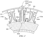
- FIG. 3 Another illustrative vane assembly 328 includes vanes 310a,b adapted for use in a gas turbine engine are shown in Fig. 3 .
- the vanes 310a, b is substantially the same as seen in Fig. 2 .
- similar reference numbers in the 300 series not discussed herein indicate features that are common between vane 10 and vanes 310a, b.
- the description of the vane 10 is hereby incorporated by reference to apply to the vanes 310a,b except in instances where it conflicts with the specific description and drawings of vane 310a,b.
- vanes 310a,b each include an airfoil and a spar 330a, b extending there through.
- Each spar 330a, b couples via a flanged end 360a,b to the turbine case 320 via a carrier 331a,b that receives the ends of the respective spars.
- Seals 366a,b are arranged between the seal panel 346 and the opposite endwalls of the spars and vanes, but may be sealed in other known configurations as well.
- the vanes 310a is supported by the spar 330a and does not include a structural rod.
- spar 330b could be coupled to the strod instead of the carrier.
- vane 310b has a structural rod 326b, which extends through the vane 310b and the structural rod 330b has a t-shaped terminal end 363b that is coupled to a keyed opening in the seal panel 346.
- Seal panel 346 is keyed as a hub to receive the t-shaped terminal end 363b and couple to the structural rod upon rotation of the t-shaped terminal 363b end by 90 degrees in a cam-lock configuration.
- seal panel-support assembly 322b includes a bolt or other threaded fastener 323b configured to extend through case 320 into and mate with a threaded interior of the STROD 326b.
- vane 310b is shown with a similar seal 366b configuration as vanes 310a, it may alternatively include a terminal end platform and seal configuration as seen in Fig. 2 . Furthermore, vane 310b may alternatively be assembled with structural rod 326b and without spar 330b.
- STRODs are not located in each consecutive airfoil.
- STRODSs are placed in every third or fourth airfoil along a seal panel and equally spaced around the annular seal panel 346 to equally distribute the forces exerted on the seal plate 346 to the turbine case 320.
- STRODs are placed in at least three locations to allow for location adjustment of the seal panel 346 relative to the central axis of the engine or other components.
- FIG. 4 Another illustrative vane assembly 428 includes vanes 410 adapted for use in a gas turbine engine are shown in Fig. 4 .
- the vanes 10 is substantially the same as seen in Figs. 2-3 . Accordingly, similar reference numbers in the 400 series not discussed herein indicate features that are common between vane 10 and vanes 410.
- the description of the vane 10 is hereby incorporated by reference to apply to the vanes 410 except in instances where it conflicts with the specific description and drawings of vane 410.
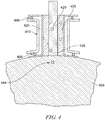
- FIG. 4 An alternative STROD embodiment is depicted in Fig. 4 in which a vane 410 includes a spar 430 extending there through and a STROD 426 extending through the spar as previously described with respect to Figs. 2-3 .
- each of the spar 420 and the STROD 426 includes a plurality of impingement holes 429 for directing cooling airflow within the vane 410.
- one or both of STROD and spar in Figs. 1-3 may include impingement holes.
- the STROD 426 is secured to a mount location of annular seal panel 446 via a pin 444 although other disclosed securing mechanisms can be used.
- structural rods may be inserted through the turbine case, and vane, and couple to the seal plate. In this manner, loads applied to the seal plate are transferred via the structural rod to the turbine case thereby maintaining the integrity of the CMC vane. Further, by inserting structural rods, the radial position of the seal plate relative to a rotating seal element of the turbine may be tuned to a particular radial position thereby controlling thrust.
Landscapes
- Engineering & Computer Science (AREA)
- Mechanical Engineering (AREA)
- General Engineering & Computer Science (AREA)
- Chemical & Material Sciences (AREA)
- Ceramic Engineering (AREA)
- Materials Engineering (AREA)
- Turbine Rotor Nozzle Sealing (AREA)
Abstract
Description
- The present disclosure relates generally to vanes used in gas turbine engines, and more specifically to structural rods positioned within one or more vanes to support an annular seal panel.
- Engines, and particularly gas turbine engines, are used to power aircraft, watercraft, power generators and the like. Gas turbine engines typically include a compressor, a combustor, and a turbine. The compressor compresses air drawn into the engine and delivers high-pressure air to the combustor. The combustor is a component or area of a gas turbine engine where combustion takes place. In a gas turbine engine, the combustor receives high-pressure air and adds fuel to the air, which is burned to produce hot, high-pressure gas. After burning the fuel, the hot, high-pressure gas is passed from the combustor to the turbine. The turbine extracts work from the hot, high-pressure gas to drive the compressor and residual energy is used for propulsion or sometimes to drive an output shaft.
- Turbines typically include static airfoils, or vanes that cooperate with an annular seal plate, to regulate the flow of air and the relative pressures between turbines located forward and aft these static airfoils. These vanes can be made of ceramic matrix composite (CMC) materials to reduce the cooling air usage, increase turbine entry temperatures, reduce weight and increase turbine efficiency when compared to vanes of other materials. When these vanes are coupled to the seal plate, loads (typically bending loads) incurred by the seal plate are transferred to the CMC vane. CMC components often have lower material strength than similar metallic components. Accordingly, new techniques and configurations are needed to tailor the distribution of loads from seal plate mounting.
- The present disclosure may comprise one or more of the following features and combinations thereof.
- A turbine section for a gas turbine engine can include a turbine case that extends around a central axis and a turbine vane assembly coupled to the turbine case. The turbine vane assembly includes a plurality of airfoils made from ceramic matrix composite materials that extend across a primary gas path of the turbine section and a plurality of spars made of metallic materials that extend radially through corresponding airfoils to support the corresponding airfoils relative to the turbine case. an annular seal panel mounted to extend radially inward of the turbine vane assembly and configured to resist the movement of gasses along the central axis without interacting with the airfoil of the turbine vane assembly, The turbine section further has a panel-support assembly that extends from the turbine case to the seal panel to fix the seal panel in place relative to the turbine case. The panel-support assembly including a plurality of structural rods that each extend radially through a corresponding airfoil such that each structural rod is shielded by the corresponding airfoil from hot gasses moving through the primary gas path of the turbine section.
- In some embodiments, each of the plurality of structural rods includes a shaft that extends through the airfoil and a retainer arranged radially inward of the airfoil and the retainer is sized to block movement of the shaft out of the airfoil via radially outward motion of the corresponding structural rod. Each of the plurality of structural rods includes a mount flange arranged radially inward of the airfoil of the turbine vane and the annular seal panel is coupled to the mount flange. The shaft of the panel-support assembly has threads at a radially outer end and the panel-support assembly includes nuts that engage the threads.
- In some embodiments, the spar of the turbine vane assembly defines a radially-extending passageway and the structural rods of the panel-support assembly each extend through a corresponding radially-extending passageway defined by a spar.
- In some embodiments, the annular seal panel includes a hub and a seal land that provides a sealing surface configured to be engaged by a rotating component to form a seal during operation of the gas turbine engine. A turbine rotor is mounted for rotation about the central axis.
- The turbine rotor includes a forward turbine wheel arranged axially forward of the turbine vane assembly along the central axis, an aft turbine wheel assembly arranged axially aft of the turbine vane assembly along the central axis, and a seal located therebetween that engages the seal land of the annular seal panel to provide a seal during operation of the gas turbine engine. The seal includes a number of knife rings that engage the seal land of the annular seal panel.
- According to another embodiment, a turbine section for a gas turbine engine includes a turbine case that extends around a central axis and a turbine vane assembly coupled to the turbine case. The turbine vane assembly including at least one airfoil made from ceramic matrix composite material that extends across a primary gas path of the turbine section, An annular seal panel is mounted to extend radially inward of the turbine vane assembly and configured to resist the movement of gasses along the central axis without interacting with the airfoil of the turbine vane assembly. Additionally, a panel-support assembly extends from the turbine case to the seal panel to fix the seal panel in place relative to the turbine case. The panel-support assembly including at least one structural rod that extends radially through a corresponding airfoil such that the at least one structural rod is shielded by the corresponding airfoil from hot gasses moving through the primary gas path of the turbine section.
- In some embodiments, the turbine vane assembly comprises a plurality of airfoils and airfoils adjacent to the at least one airfoil are devoid of structural rods. The panel-support assembly comprises a plurality of structural rods radially spaced apart around the turbine case so that the structural rods extend through every second, third, or every fourth airfoil of the plurality of airfoils.
- In some embodiments, the panel-support assembly further includes a nut extending through an opening in the turbine casing and into a threaded opening in the interior of the structural rod, and the radial position of the seal panel relative to the turbine case may be changed by rotating the nut along the threaded opening. The distal end of the structural rod includes a mount flange arranged radially inward of the airfoil of the turbine vane and the annular seal panel is coupled to the mount flange. The mount flange can be a t-shaped flange configured to be received in a keyed opening in the seal panel or the mount flange and the seal panel are coupled together via one of a bolt, pin, cam-lock braze or weld.
- In some embodiments, the turbine vane assembly further comprises a spar extending through the airfoil and surrounding the structural rod.
- In some embodiments, the structural rod is formed to include a plurality of impingement holes for moving cooling air into the airfoil. The annular seal panel includes a hub and a seal land that provides a sealing surface configured to be engaged by a rotating component to form a seal during operation of the gas turbine engine.
- In some embodiments, a turbine rotor is mounted for rotation about the central axis, the turbine rotor including a forward turbine wheel arranged axially forward of the turbine vane assembly along the central axis and an aft turbine wheel assembly arranged axially aft of the turbine vane assembly along the central axis. A seal rotor engages the seal land of the annular seal panel to provide a seal during operation of the gas turbine engine. The shaft of the panel-support assembly has threads at a radially outer end and the panel-support assembly includes a nut that engages the threads.
- These and other features of the present disclosure will become more apparent from the following description of the illustrative embodiments.
-
-
Fig. 1 is a perspective cut-away view of a turbine engine showing that the engine includes a turbine arranged aft of a compressor, and a combustor to receive hot, high pressure air produced in the compressor and combustor; -
Fig. 2 is a sectional view of a portion of the turbine ofFig. 1 showing an vane and seal plate coupled to a case via a seal panel mount assembly with a structural rod that extends through the vane to support the seal panel relative to the case; -
Fig. 3 is a cross-sectional view of the turbine depicting a vane assembly embodiment along a segment of an annular seal panel supported by a structural rod extending through the vane; and -
Fig. 4 shows a vane according to the embodiments ofFigures 1-3 in which a structural rod and a spar include impingement holes. - For the purposes of promoting an understanding of the principles of the disclosure, reference will now be made to a number of illustrative embodiments illustrated in the drawings and specific language will be used to describe the same.
- The arrangement of an
illustrative vane 10 in agas turbine engine 100 is shown inFig. 1 . Thegas turbine engine 100 includes acompressor 115, acombustor 121, and aturbine 140 housing a plurality ofvanes 10 that form a vane assembly. An output shaft is driven by theturbine 140 and may drive a propeller, a gearbox, a pump, or fan depending on the application of thegas turbine engine 100. - Each of the
vanes 10 is located in the turbine and can be secured via a sealpanel mount assembly 22 and/or a spar to aturbine case 20. Aturbine rotor 48, includes ashaft 52, aforward turbine wheel 50 andaft turbine wheel 56, located forward and aft, respectively of thevane 10.Turbine rotor 48 further includes arotating component 54, that moves with the rotation of theshaft 52 and is positioned radially interior to, and directly under thevane 10. - A
vane assembly 28 can include one ormore vanes 10, made of ceramic matrix composite (CMC) material, that each has anouter endwall 32, aninner endwall 40 and anairfoil 36 extending therebetween. In some embodiments,vane assembly 28 includes ametal spar 330b extending through the interior of the airfoil 26 from theouter endwall 32 to theinner endwall 40. Spar 330b includes a flanged head 360b to couple to ablade carrier 331 coupled to theturbine case 20 as further disclosed with respect toFig. 3 . - Seal panel-
support assembly 22 includes at least structural rod 26 and a retainer such as anut 24. Structural rod (STROD) 26 can be made of metal, and extends from theturbine case 20 through thevane assembly 28 inside of each of theairfoil 36 and theoptional spar 330b, and terminates at aterminal end 62. Seal panel-support assembly 22 can include a plurality of structural rods 26 and retainers spaced equidistantly about theturbine case 20. Structural rod 26 can be formed of a metallic material and is shielded within theairfoil 36 from hot gasses moving through a primary gas path of the turbine section of the engine. As illustrated inFig 2 , Structural rod 26 extends through anopening 64 formed in theturbine case 20 and anut 24 or other screw-type fitting is threaded onto an end of the STROD 26 thereby allowing radial adjustment of the position of the STROD 26. - Structural rod
terminal end 62 can be formed to include an inner platform retainer structure that is coupled to the inner endwall 42 of thevane assembly 28 via aseal 66. Structural rodterminal end 62 is also coupled to anannular seal panel 46 to fix the radial position of the seal panel in place relative to theturbine case 20.Seal panel 46 acts as a divider plate between the forward andaft turbine wheels Annular seal panel 46 extends between theterminal end 62 of the structural rod and the alignedseal rotor 54. In some embodiments, in lieu ofseal rotor 54, seal may part of forward or aft disk, or could be incorporated into a coverplate mounted to the forward or aft disk. In some embodiments the structural rod terminal end, or mountflange 62 is coupled to theannular seal panel 46 via a securing pin, bolt, braze, or weld joint 44. In this manner, the relative radial adjustment of the position of the STROD 26 corresponds to radial adjustment a contact, or clearance space between knife rings 55 of theseal rotor 54 and the adistal seal land 47 of theseal panel 46 thereby allowing the space to be tuned to adjust the thrust balance. Additionallynut 24 or other screw-type fitting can radially adjust the position of the STROD 26 and corresponding seal panel and airfoil to place tension on the structural rod. Further, loads experienced in theseal panel 46 are transferred through the STROD and out to theturbine case 20, thereby avoiding exerting bending loads on thevane 10. - Another illustrative vane assembly 328 includes
vanes 310a,b adapted for use in a gas turbine engine are shown inFig. 3 . As seen inFig. 3 , thevanes 310a, b is substantially the same as seen inFig. 2 . Accordingly, similar reference numbers in the 300 series not discussed herein indicate features that are common betweenvane 10 andvanes 310a, b. The description of thevane 10 is hereby incorporated by reference to apply to thevanes 310a,b except in instances where it conflicts with the specific description and drawings ofvane 310a,b. - As is depicted,
vanes 310a,b each include an airfoil and aspar 330a, b extending there through. Eachspar 330a, b couples via a flanged end 360a,b to theturbine case 320 via a carrier 331a,b that receives the ends of the respective spars.Seals 366a,b are arranged between theseal panel 346 and the opposite endwalls of the spars and vanes, but may be sealed in other known configurations as well. In this embodiment thevanes 310a is supported by thespar 330a and does not include a structural rod. Alternatively,spar 330b could be coupled to the strod instead of the carrier. - In this embodiment,
vane 310b has astructural rod 326b, which extends through thevane 310b and thestructural rod 330b has a t-shapedterminal end 363b that is coupled to a keyed opening in theseal panel 346.Seal panel 346 is keyed as a hub to receive the t-shapedterminal end 363b and couple to the structural rod upon rotation of the t-shaped terminal 363b end by 90 degrees in a cam-lock configuration. In this embodiment, seal panel-support assembly 322b includes a bolt or other threadedfastener 323b configured to extend throughcase 320 into and mate with a threaded interior of theSTROD 326b. Althoughvane 310b is shown with asimilar seal 366b configuration asvanes 310a, it may alternatively include a terminal end platform and seal configuration as seen inFig. 2 . Furthermore,vane 310b may alternatively be assembled withstructural rod 326b and withoutspar 330b. - As seen in
Fig. 3 , STRODs are not located in each consecutive airfoil. In a preferred embodiment, STRODSs are placed in every third or fourth airfoil along a seal panel and equally spaced around theannular seal panel 346 to equally distribute the forces exerted on theseal plate 346 to theturbine case 320. In illustrated embodiments, STRODs are placed in at least three locations to allow for location adjustment of theseal panel 346 relative to the central axis of the engine or other components. - Another illustrative vane assembly 428 includes
vanes 410 adapted for use in a gas turbine engine are shown inFig. 4 . As seen inFig. 4 , thevanes 10 is substantially the same as seen inFigs. 2-3 . Accordingly, similar reference numbers in the 400 series not discussed herein indicate features that are common betweenvane 10 andvanes 410. The description of thevane 10 is hereby incorporated by reference to apply to thevanes 410 except in instances where it conflicts with the specific description and drawings ofvane 410. - An alternative STROD embodiment is depicted in
Fig. 4 in which avane 410 includes a spar 430 extending there through and aSTROD 426 extending through the spar as previously described with respect toFigs. 2-3 . In this embodiment, each of thespar 420 and theSTROD 426 includes a plurality of impingement holes 429 for directing cooling airflow within thevane 410. However, one or both of STROD and spar inFigs. 1-3 may include impingement holes. As seen in this embodiment, theSTROD 426 is secured to a mount location of annular seal panel 446 via apin 444 although other disclosed securing mechanisms can be used. - When vanes are coupled to a seal plate in other designs, loads (typically bending loads) incurred by the seal plate are transferred to the CMC vane. CMC components often have lower material strength than similar metallic components. Accordingly, new techniques and configurations are provided by designs herein to tailor the positional mounting of a vane and a corresponding seal panel in a turbine engine to control forces experienced by the vane and tailor the thrust generated between forward and aft turbines.
- In order to transfer these loads away from the CMC vane, structural rods may be inserted through the turbine case, and vane, and couple to the seal plate. In this manner, loads applied to the seal plate are transferred via the structural rod to the turbine case thereby maintaining the integrity of the CMC vane. Further, by inserting structural rods, the radial position of the seal plate relative to a rotating seal element of the turbine may be tuned to a particular radial position thereby controlling thrust.
- While the disclosure has been illustrated and described in detail in the foregoing drawings and description, the same is to be considered as exemplary and not restrictive in character, it being understood that only illustrative embodiments thereof have been shown and described and that all changes and modifications that come within the spirit of the disclosure are desired to be protected.
Claims (15)
- A turbine section for a gas turbine engine (100), the turbine section comprising
a turbine case (20) that extends around a central axis,
a turbine vane assembly coupled to the turbine case (20), the turbine vane assembly including at least one airfoil (36), preferably a plurality of airfoils (36) made from ceramic matrix composite materials that extend across a primary gas path of the turbine section,
an annular seal panel (46, 346, 446) mounted to extend radially inward of the turbine vane assembly and configured to resist the movement of gasses along the central axis without interacting with the airfoil (36) of the turbine vane assembly, and
a panel-support assembly (22, 322b) that extends from the turbine case (20) to the seal panel (46, 346, 446) to fix the seal panel (46, 346, 446) in place relative to the turbine case (20), the panel-support assembly (22, 322b) including at least one structural rod, preferably a plurality of structural rods (26) that each extend radially through a corresponding airfoil (36) such that each structural rod (26) is shielded by the corresponding airfoil (36) from hot gasses moving through the primary gas path of the turbine section. - The turbine section of claim 1, wherein the turbine vane assembly further comprises a spar (330a, 330b) extending through the airfoil (36) and surrounding the structural rod (26) or and wherein the turbine vane assembly comprises a plurality of spars (330a, 330b) made of metallic materials that extend radially through corresponding airfoils (36) to support the corresponding airfoils (36) relative to the turbine case (20).
- The turbine section of claim 1 or 2, wherein each of the plurality of structural rods (26) includes a shaft that extends through the airfoil (36) and a retainer (24) arranged radially inward of the airfoil (36), the retainer (24) being sized to block movement of the shaft out of the airfoil (36) via radially outward motion of the corresponding structural rod (26).
- The turbine section of claim 3, wherein each of the plurality of structural rods (26) includes a mount flange (62) arranged radially inward of the airfoil (36) of the turbine vane and the annular seal panel (46, 346, 446) is coupled to the mount flange (62) or wherein the distal end of the structural rod (26) includes a mount flange (62) arranged radially inward of the airfoil (36) of the turbine vane and the annular seal panel (46, 346, 446) is coupled to the mount flange (62).
- The turbine section of claim 2, wherein the spar (330a, 330b) of the turbine vane assembly defines a radially-extending passageway and the structural rods (26) of the panel-support assembly (22, 322b) each extend through a corresponding radially-extending passageway defined by a spar (330a, 330b).
- The turbine section of claim 1, wherein the annular seal panel (46, 346, 446) includes a hub and a seal land that provides a sealing surface configured to be engaged by a rotating component to form a seal during operation of the gas turbine engine.
- The turbine section of claim 6, further comprising a turbine rotor (48) mounted for rotation about the central axis, the turbine rotor (48) including a forward turbine wheel (50) arranged axially forward of the turbine vane assembly along the central axis, an aft turbine wheel assembly arranged axially aft of the turbine vane assembly along the central axis, and a seal located therebetween that engages the seal land (47) of the annular seal panel (46, 346, 446) to provide a seal during operation of the gas turbine engine (100).
- The turbine section of claim 7, wherein the seal includes a number of knife rings (55) that engage the seal land (47) of the annular seal panel (46, 346, 446).
- The turbine section of claim 1, wherein the turbine vane assembly comprises a plurality of airfoils (36) and airfoils (36) adjacent to the at least one airfoil (36) are devoid of structural rods (26).
- The turbine section of claim 9, wherein the panel-support assembly (22, 322b) comprises a plurality of structural rods (26) radially spaced apart around the turbine case (20) so that the structural rods (26) extend through every second, third, or every fourth airfoil (36) of the plurality of airfoils (36).
- The turbine section of claim 3, wherein the mount flange (62) is a t-shaped flange configured to be received in a keyed opening in the seal panel (46, 346, 446).
- The turbine section of claim 3, wherein the mount flange (62) and the seal panel (46, 346, 446) are coupled together via one of a bolt (323b), pin, cam-lock, braze or weld.
- The turbine section of claim 1, wherein the structural rod (26) is formed to include a plurality of impingement holes (429) for moving cooling air into the airfoil (36).
- The turbine section of claim 13, further comprising a turbine rotor (48) mounted for rotation about the central axis, the turbine rotor (48) including a forward turbine wheel (50) arranged axially forward of the turbine vane assembly along the central axis, an aft turbine wheel assembly arranged axially aft of the turbine vane assembly along the central axis, and a seal rotor that engages the seal land (47) of the annular seal panel (46, 346, 446) to provide a seal during operation of the gas turbine engine (100).
- The turbine section of one of the preceding claims, wherein the shaft of the panel-support assembly (22, 322b) has threads at a radially outer end and the panel-support assembly (22, 322b) includes a nut (24) or nuts (24) that engages the threads or wherein the panel-support assembly (22, 322b) includes a nut (24) extending through an opening in the turbine case (20) and into a threaded opening in the interior of the structural rod (26), and the radial position of the seal panel (46, 346, 446) relative to the turbine case (20) may be changed by rotating the nut (24) along the threaded opening.
Applications Claiming Priority (1)
| Application Number | Priority Date | Filing Date | Title |
|---|---|---|---|
| US16/041,318 US10830063B2 (en) | 2018-07-20 | 2018-07-20 | Turbine vane assembly with ceramic matrix composite components |
Publications (2)
| Publication Number | Publication Date |
|---|---|
| EP3597866A1 true EP3597866A1 (en) | 2020-01-22 |
| EP3597866B1 EP3597866B1 (en) | 2022-12-21 |
Family
ID=67438095
Family Applications (1)
| Application Number | Title | Priority Date | Filing Date |
|---|---|---|---|
| EP19187172.2A Active EP3597866B1 (en) | 2018-07-20 | 2019-07-19 | Turbine section for a gas turbine engine |
Country Status (3)
| Country | Link |
|---|---|
| US (1) | US10830063B2 (en) |
| EP (1) | EP3597866B1 (en) |
| CA (1) | CA3050048A1 (en) |
Cited By (3)
| Publication number | Priority date | Publication date | Assignee | Title |
|---|---|---|---|---|
| EP3730739A1 (en) * | 2019-04-23 | 2020-10-28 | Rolls-Royce plc | Turbine assembly for a gas turbine engine with ceramic matrix composite vane |
| EP3730738A1 (en) * | 2019-04-23 | 2020-10-28 | Rolls-Royce plc | Turbine assembly for a gas turbine engine with ceramic matrix composite vane |
| FR3108673A1 (en) * | 2020-03-27 | 2021-10-01 | Safran Aircraft Engines | TURBINE OF TURBOMACHINE WITH DISTRIBUTOR IN CMC WITH BLENDING OF FULL MATS AT THE CROWN |
Families Citing this family (6)
| Publication number | Priority date | Publication date | Assignee | Title |
|---|---|---|---|---|
| EP3805525A1 (en) | 2019-10-09 | 2021-04-14 | Rolls-Royce plc | Turbine vane assembly incorporating ceramic matric composite materials |
| US11174794B2 (en) * | 2019-11-08 | 2021-11-16 | Raytheon Technologies Corporation | Vane with seal and retainer plate |
| US11156105B2 (en) * | 2019-11-08 | 2021-10-26 | Raytheon Technologies Corporation | Vane with seal |
| US11499443B2 (en) * | 2020-12-21 | 2022-11-15 | Raytheon Technologies Corporation | Ceramic wall seal interface cooling |
| US11454129B1 (en) * | 2021-04-02 | 2022-09-27 | Raytheon Technologies Corporation | CMC component flow discourager flanges |
| US11913348B1 (en) * | 2022-10-12 | 2024-02-27 | Rtx Corporation | Gas turbine engine vane and spar combination with variable air flow path |
Citations (6)
| Publication number | Priority date | Publication date | Assignee | Title |
|---|---|---|---|---|
| US5616001A (en) * | 1995-01-06 | 1997-04-01 | Solar Turbines Incorporated | Ceramic cerami turbine nozzle |
| US8382432B2 (en) * | 2010-03-08 | 2013-02-26 | General Electric Company | Cooled turbine rim seal |
| WO2014105270A2 (en) * | 2012-12-18 | 2014-07-03 | United Technologies Corporation | Airfoil assembly with paired endwall contouring |
| WO2014200831A1 (en) * | 2013-06-14 | 2014-12-18 | United Technologies Corporation | Variable area gas turbine engine component having movable spar and shell |
| US20170101880A1 (en) * | 2015-10-12 | 2017-04-13 | Rolls-Royce North American Technologies, Inc. | Fabric seal and assembly for gas turbine engine |
| US9970317B2 (en) * | 2014-10-31 | 2018-05-15 | Rolls-Royce North America Technologies Inc. | Vane assembly for a gas turbine engine |
Family Cites Families (30)
| Publication number | Priority date | Publication date | Assignee | Title |
|---|---|---|---|---|
| GB2234299B (en) | 1989-07-06 | 1994-01-05 | Rolls Royce Plc | Mounting system for engine components having dissimilar coefficients of thermal expansion |
| US5149250A (en) | 1991-02-28 | 1992-09-22 | General Electric Company | Gas turbine vane assembly seal and support system |
| GB2307520B (en) | 1995-11-14 | 1999-07-07 | Rolls Royce Plc | A gas turbine engine |
| US6325593B1 (en) | 2000-02-18 | 2001-12-04 | General Electric Company | Ceramic turbine airfoils with cooled trailing edge blocks |
| US6398488B1 (en) | 2000-09-13 | 2002-06-04 | General Electric Company | Interstage seal cooling |
| US6514046B1 (en) | 2000-09-29 | 2003-02-04 | Siemens Westinghouse Power Corporation | Ceramic composite vane with metallic substructure |
| US6558114B1 (en) | 2000-09-29 | 2003-05-06 | Siemens Westinghouse Power Corporation | Gas turbine with baffle reducing hot gas ingress into interstage disc cavity |
| US6682299B2 (en) | 2001-11-15 | 2004-01-27 | General Electric Company | Variable stator vane support arrangement |
| US6648597B1 (en) | 2002-05-31 | 2003-11-18 | Siemens Westinghouse Power Corporation | Ceramic matrix composite turbine vane |
| US7762766B2 (en) | 2006-07-06 | 2010-07-27 | Siemens Energy, Inc. | Cantilevered framework support for turbine vane |
| US7371004B1 (en) | 2007-03-09 | 2008-05-13 | Hamilton Beach Brands, Inc. | Travel mug configured to blend food and method thereof |
| US9353643B2 (en) * | 2007-04-10 | 2016-05-31 | United Technologies Corporation | Variable stator vane assembly for a turbine engine |
| US8454303B2 (en) | 2010-01-14 | 2013-06-04 | General Electric Company | Turbine nozzle assembly |
| US8740554B2 (en) | 2011-01-11 | 2014-06-03 | United Technologies Corporation | Cover plate with interstage seal for a gas turbine engine |
| US9097141B2 (en) * | 2011-09-15 | 2015-08-04 | Pratt & Whitney Canada Corp. | Axial bolting arrangement for mid turbine frame |
| US9540940B2 (en) | 2012-03-12 | 2017-01-10 | General Electric Company | Turbine interstage seal system |
| US9546557B2 (en) | 2012-06-29 | 2017-01-17 | General Electric Company | Nozzle, a nozzle hanger, and a ceramic to metal attachment system |
| US20140255174A1 (en) | 2012-12-21 | 2014-09-11 | United Technologies Corporation | Manufacture of full ring strut vane pack |
| WO2014133721A1 (en) | 2013-02-27 | 2014-09-04 | United Technologies Corporation | Gas turbine engine thin wall composite vane airfoil |
| US9719363B2 (en) | 2014-06-06 | 2017-08-01 | United Technologies Corporation | Segmented rim seal spacer for a gas turbine engine |
| EP3009608B1 (en) | 2014-10-02 | 2019-10-30 | United Technologies Corporation | Vane assembly with trapped segmented vane structures |
| US10094239B2 (en) * | 2014-10-31 | 2018-10-09 | Rolls-Royce North American Technologies Inc. | Vane assembly for a gas turbine engine |
| US9915159B2 (en) * | 2014-12-18 | 2018-03-13 | General Electric Company | Ceramic matrix composite nozzle mounted with a strut and concepts thereof |
| US10309240B2 (en) | 2015-07-24 | 2019-06-04 | General Electric Company | Method and system for interfacing a ceramic matrix composite component to a metallic component |
| US20170051619A1 (en) | 2015-08-18 | 2017-02-23 | General Electric Company | Cmc nozzles with split endwalls for gas turbine engines |
| US10794289B2 (en) | 2016-08-09 | 2020-10-06 | General Electric Company | Modulated turbine component cooling |
| US10851658B2 (en) | 2017-02-06 | 2020-12-01 | General Electric Company | Nozzle assembly and method for forming nozzle assembly |
| US20180328187A1 (en) | 2017-05-09 | 2018-11-15 | General Electric Company | Turbine engine with an airfoil and insert |
| US10458260B2 (en) | 2017-05-24 | 2019-10-29 | General Electric Company | Nozzle airfoil decoupled from and attached outside of flow path boundary |
| US10569481B2 (en) | 2017-06-26 | 2020-02-25 | General Electric Company | Shaped composite ply layups and methods for shaping composite ply layups |
-
2018
- 2018-07-20 US US16/041,318 patent/US10830063B2/en active Active
-
2019
- 2019-07-18 CA CA3050048A patent/CA3050048A1/en active Pending
- 2019-07-19 EP EP19187172.2A patent/EP3597866B1/en active Active
Patent Citations (6)
| Publication number | Priority date | Publication date | Assignee | Title |
|---|---|---|---|---|
| US5616001A (en) * | 1995-01-06 | 1997-04-01 | Solar Turbines Incorporated | Ceramic cerami turbine nozzle |
| US8382432B2 (en) * | 2010-03-08 | 2013-02-26 | General Electric Company | Cooled turbine rim seal |
| WO2014105270A2 (en) * | 2012-12-18 | 2014-07-03 | United Technologies Corporation | Airfoil assembly with paired endwall contouring |
| WO2014200831A1 (en) * | 2013-06-14 | 2014-12-18 | United Technologies Corporation | Variable area gas turbine engine component having movable spar and shell |
| US9970317B2 (en) * | 2014-10-31 | 2018-05-15 | Rolls-Royce North America Technologies Inc. | Vane assembly for a gas turbine engine |
| US20170101880A1 (en) * | 2015-10-12 | 2017-04-13 | Rolls-Royce North American Technologies, Inc. | Fabric seal and assembly for gas turbine engine |
Cited By (5)
| Publication number | Priority date | Publication date | Assignee | Title |
|---|---|---|---|---|
| EP3730739A1 (en) * | 2019-04-23 | 2020-10-28 | Rolls-Royce plc | Turbine assembly for a gas turbine engine with ceramic matrix composite vane |
| EP3730738A1 (en) * | 2019-04-23 | 2020-10-28 | Rolls-Royce plc | Turbine assembly for a gas turbine engine with ceramic matrix composite vane |
| US10975708B2 (en) | 2019-04-23 | 2021-04-13 | Rolls-Royce Plc | Turbine section assembly with ceramic matrix composite vane |
| US11008880B2 (en) | 2019-04-23 | 2021-05-18 | Rolls-Royce Plc | Turbine section assembly with ceramic matrix composite vane |
| FR3108673A1 (en) * | 2020-03-27 | 2021-10-01 | Safran Aircraft Engines | TURBINE OF TURBOMACHINE WITH DISTRIBUTOR IN CMC WITH BLENDING OF FULL MATS AT THE CROWN |
Also Published As
| Publication number | Publication date |
|---|---|
| US10830063B2 (en) | 2020-11-10 |
| US20200024972A1 (en) | 2020-01-23 |
| CA3050048A1 (en) | 2020-01-20 |
| EP3597866B1 (en) | 2022-12-21 |
Similar Documents
| Publication | Publication Date | Title |
|---|---|---|
| EP3597866B1 (en) | Turbine section for a gas turbine engine | |
| US7094029B2 (en) | Methods and apparatus for controlling gas turbine engine rotor tip clearances | |
| US10458263B2 (en) | Turbine shroud with sealing features | |
| US8425194B2 (en) | Clamped plate seal | |
| EP2938860B1 (en) | Turbine exhaust case multi-piece frame | |
| EP2938837B1 (en) | Gas turbine seal assembly and seal support | |
| US11215080B1 (en) | Turbine shroud assembly with integrated ceramic matrix composite component support pins | |
| US11378012B2 (en) | Insert-mounted turbine assembly for a gas turbine engine | |
| US9850780B2 (en) | Plate for directing flow and film cooling of components | |
| EP3623582B1 (en) | Multi-piece carrier assembly for mounting ceramic matrix composite seal segments | |
| US11193393B2 (en) | Turbine section assembly with ceramic matrix composite vane | |
| US20200149400A1 (en) | Blade mounting | |
| US10472987B2 (en) | Heat shield for a casing | |
| US20190338644A1 (en) | Drive Shaft | |
| US11053817B2 (en) | Turbine shroud assembly with ceramic matrix composite blade track segments and full hoop carrier | |
| US10883376B2 (en) | Turbine vane assembly with ceramic matrix composite vanes | |
| US10934859B2 (en) | Turbine blade comprising ceramic matrix composite materials | |
| US11635026B1 (en) | Fan case assembly for a gas turbine engine | |
| EP3819463B1 (en) | Turbine assembly with ceramic matrix composite components and interstage sealing features | |
| US11085318B1 (en) | Turbine shroud assembly with multi-piece support for ceramic matrix composite material seal segments | |
| EP3719262B1 (en) | Seal assembly for a gas turbine engine | |
| EP3249166A1 (en) | Turbine shroud | |
| US12460557B1 (en) | Variable pitch airfoil assembly for a gas turbine engine |
Legal Events
| Date | Code | Title | Description |
|---|---|---|---|
| PUAI | Public reference made under article 153(3) epc to a published international application that has entered the european phase |
Free format text: ORIGINAL CODE: 0009012 |
|
| STAA | Information on the status of an ep patent application or granted ep patent |
Free format text: STATUS: THE APPLICATION HAS BEEN PUBLISHED |
|
| AK | Designated contracting states |
Kind code of ref document: A1 Designated state(s): AL AT BE BG CH CY CZ DE DK EE ES FI FR GB GR HR HU IE IS IT LI LT LU LV MC MK MT NL NO PL PT RO RS SE SI SK SM TR |
|
| AX | Request for extension of the european patent |
Extension state: BA ME |
|
| RIN1 | Information on inventor provided before grant (corrected) |
Inventor name: VETTERS, DANIEL K. Inventor name: FREEMAN, TED J. Inventor name: NASH, CHRISTOPHER Inventor name: KOENIG, ERIC Inventor name: WHITTLE, MICHAEL |
|
| RAP1 | Party data changed (applicant data changed or rights of an application transferred) |
Owner name: ROLLS-ROYCE PLC Owner name: ROLLS-ROYCE NORTH AMERICAN TECHNOLOGIES, INC. Owner name: ROLLS-ROYCE CORPORATION |
|
| STAA | Information on the status of an ep patent application or granted ep patent |
Free format text: STATUS: REQUEST FOR EXAMINATION WAS MADE |
|
| 17P | Request for examination filed |
Effective date: 20200402 |
|
| RBV | Designated contracting states (corrected) |
Designated state(s): AL AT BE BG CH CY CZ DE DK EE ES FI FR GB GR HR HU IE IS IT LI LT LU LV MC MK MT NL NO PL PT RO RS SE SI SK SM TR |
|
| STAA | Information on the status of an ep patent application or granted ep patent |
Free format text: STATUS: EXAMINATION IS IN PROGRESS |
|
| 17Q | First examination report despatched |
Effective date: 20200901 |
|
| GRAP | Despatch of communication of intention to grant a patent |
Free format text: ORIGINAL CODE: EPIDOSNIGR1 |
|
| STAA | Information on the status of an ep patent application or granted ep patent |
Free format text: STATUS: GRANT OF PATENT IS INTENDED |
|
| INTG | Intention to grant announced |
Effective date: 20220816 |
|
| GRAS | Grant fee paid |
Free format text: ORIGINAL CODE: EPIDOSNIGR3 |
|
| GRAA | (expected) grant |
Free format text: ORIGINAL CODE: 0009210 |
|
| STAA | Information on the status of an ep patent application or granted ep patent |
Free format text: STATUS: THE PATENT HAS BEEN GRANTED |
|
| AK | Designated contracting states |
Kind code of ref document: B1 Designated state(s): AL AT BE BG CH CY CZ DE DK EE ES FI FR GB GR HR HU IE IS IT LI LT LU LV MC MK MT NL NO PL PT RO RS SE SI SK SM TR |
|
| REG | Reference to a national code |
Ref country code: GB Ref legal event code: FG4D |
|
| REG | Reference to a national code |
Ref country code: CH Ref legal event code: EP |
|
| REG | Reference to a national code |
Ref country code: DE Ref legal event code: R096 Ref document number: 602019023322 Country of ref document: DE |
|
| REG | Reference to a national code |
Ref country code: AT Ref legal event code: REF Ref document number: 1539175 Country of ref document: AT Kind code of ref document: T Effective date: 20230115 |
|
| REG | Reference to a national code |
Ref country code: IE Ref legal event code: FG4D |
|
| REG | Reference to a national code |
Ref country code: LT Ref legal event code: MG9D |
|
| REG | Reference to a national code |
Ref country code: NL Ref legal event code: MP Effective date: 20221221 |
|
| PG25 | Lapsed in a contracting state [announced via postgrant information from national office to epo] |
Ref country code: SE Free format text: LAPSE BECAUSE OF FAILURE TO SUBMIT A TRANSLATION OF THE DESCRIPTION OR TO PAY THE FEE WITHIN THE PRESCRIBED TIME-LIMIT Effective date: 20221221 Ref country code: NO Free format text: LAPSE BECAUSE OF FAILURE TO SUBMIT A TRANSLATION OF THE DESCRIPTION OR TO PAY THE FEE WITHIN THE PRESCRIBED TIME-LIMIT Effective date: 20230321 Ref country code: LT Free format text: LAPSE BECAUSE OF FAILURE TO SUBMIT A TRANSLATION OF THE DESCRIPTION OR TO PAY THE FEE WITHIN THE PRESCRIBED TIME-LIMIT Effective date: 20221221 Ref country code: FI Free format text: LAPSE BECAUSE OF FAILURE TO SUBMIT A TRANSLATION OF THE DESCRIPTION OR TO PAY THE FEE WITHIN THE PRESCRIBED TIME-LIMIT Effective date: 20221221 |
|
| REG | Reference to a national code |
Ref country code: AT Ref legal event code: MK05 Ref document number: 1539175 Country of ref document: AT Kind code of ref document: T Effective date: 20221221 |
|
| PG25 | Lapsed in a contracting state [announced via postgrant information from national office to epo] |
Ref country code: RS Free format text: LAPSE BECAUSE OF FAILURE TO SUBMIT A TRANSLATION OF THE DESCRIPTION OR TO PAY THE FEE WITHIN THE PRESCRIBED TIME-LIMIT Effective date: 20221221 Ref country code: LV Free format text: LAPSE BECAUSE OF FAILURE TO SUBMIT A TRANSLATION OF THE DESCRIPTION OR TO PAY THE FEE WITHIN THE PRESCRIBED TIME-LIMIT Effective date: 20221221 Ref country code: HR Free format text: LAPSE BECAUSE OF FAILURE TO SUBMIT A TRANSLATION OF THE DESCRIPTION OR TO PAY THE FEE WITHIN THE PRESCRIBED TIME-LIMIT Effective date: 20221221 Ref country code: GR Free format text: LAPSE BECAUSE OF FAILURE TO SUBMIT A TRANSLATION OF THE DESCRIPTION OR TO PAY THE FEE WITHIN THE PRESCRIBED TIME-LIMIT Effective date: 20230322 |
|
| PG25 | Lapsed in a contracting state [announced via postgrant information from national office to epo] |
Ref country code: NL Free format text: LAPSE BECAUSE OF FAILURE TO SUBMIT A TRANSLATION OF THE DESCRIPTION OR TO PAY THE FEE WITHIN THE PRESCRIBED TIME-LIMIT Effective date: 20221221 |
|
| P01 | Opt-out of the competence of the unified patent court (upc) registered |
Effective date: 20230528 |
|
| PG25 | Lapsed in a contracting state [announced via postgrant information from national office to epo] |
Ref country code: SM Free format text: LAPSE BECAUSE OF FAILURE TO SUBMIT A TRANSLATION OF THE DESCRIPTION OR TO PAY THE FEE WITHIN THE PRESCRIBED TIME-LIMIT Effective date: 20221221 Ref country code: RO Free format text: LAPSE BECAUSE OF FAILURE TO SUBMIT A TRANSLATION OF THE DESCRIPTION OR TO PAY THE FEE WITHIN THE PRESCRIBED TIME-LIMIT Effective date: 20221221 Ref country code: PT Free format text: LAPSE BECAUSE OF FAILURE TO SUBMIT A TRANSLATION OF THE DESCRIPTION OR TO PAY THE FEE WITHIN THE PRESCRIBED TIME-LIMIT Effective date: 20230421 Ref country code: ES Free format text: LAPSE BECAUSE OF FAILURE TO SUBMIT A TRANSLATION OF THE DESCRIPTION OR TO PAY THE FEE WITHIN THE PRESCRIBED TIME-LIMIT Effective date: 20221221 Ref country code: EE Free format text: LAPSE BECAUSE OF FAILURE TO SUBMIT A TRANSLATION OF THE DESCRIPTION OR TO PAY THE FEE WITHIN THE PRESCRIBED TIME-LIMIT Effective date: 20221221 Ref country code: CZ Free format text: LAPSE BECAUSE OF FAILURE TO SUBMIT A TRANSLATION OF THE DESCRIPTION OR TO PAY THE FEE WITHIN THE PRESCRIBED TIME-LIMIT Effective date: 20221221 Ref country code: AT Free format text: LAPSE BECAUSE OF FAILURE TO SUBMIT A TRANSLATION OF THE DESCRIPTION OR TO PAY THE FEE WITHIN THE PRESCRIBED TIME-LIMIT Effective date: 20221221 |
|
| PG25 | Lapsed in a contracting state [announced via postgrant information from national office to epo] |
Ref country code: SK Free format text: LAPSE BECAUSE OF FAILURE TO SUBMIT A TRANSLATION OF THE DESCRIPTION OR TO PAY THE FEE WITHIN THE PRESCRIBED TIME-LIMIT Effective date: 20221221 Ref country code: PL Free format text: LAPSE BECAUSE OF FAILURE TO SUBMIT A TRANSLATION OF THE DESCRIPTION OR TO PAY THE FEE WITHIN THE PRESCRIBED TIME-LIMIT Effective date: 20221221 Ref country code: IS Free format text: LAPSE BECAUSE OF FAILURE TO SUBMIT A TRANSLATION OF THE DESCRIPTION OR TO PAY THE FEE WITHIN THE PRESCRIBED TIME-LIMIT Effective date: 20230421 Ref country code: AL Free format text: LAPSE BECAUSE OF FAILURE TO SUBMIT A TRANSLATION OF THE DESCRIPTION OR TO PAY THE FEE WITHIN THE PRESCRIBED TIME-LIMIT Effective date: 20221221 |
|
| REG | Reference to a national code |
Ref country code: DE Ref legal event code: R097 Ref document number: 602019023322 Country of ref document: DE |
|
| PLBE | No opposition filed within time limit |
Free format text: ORIGINAL CODE: 0009261 |
|
| STAA | Information on the status of an ep patent application or granted ep patent |
Free format text: STATUS: NO OPPOSITION FILED WITHIN TIME LIMIT |
|
| PG25 | Lapsed in a contracting state [announced via postgrant information from national office to epo] |
Ref country code: DK Free format text: LAPSE BECAUSE OF FAILURE TO SUBMIT A TRANSLATION OF THE DESCRIPTION OR TO PAY THE FEE WITHIN THE PRESCRIBED TIME-LIMIT Effective date: 20221221 |
|
| 26N | No opposition filed |
Effective date: 20230922 |
|
| PG25 | Lapsed in a contracting state [announced via postgrant information from national office to epo] |
Ref country code: SI Free format text: LAPSE BECAUSE OF FAILURE TO SUBMIT A TRANSLATION OF THE DESCRIPTION OR TO PAY THE FEE WITHIN THE PRESCRIBED TIME-LIMIT Effective date: 20221221 |
|
| PG25 | Lapsed in a contracting state [announced via postgrant information from national office to epo] |
Ref country code: MC Free format text: LAPSE BECAUSE OF FAILURE TO SUBMIT A TRANSLATION OF THE DESCRIPTION OR TO PAY THE FEE WITHIN THE PRESCRIBED TIME-LIMIT Effective date: 20221221 |
|
| PG25 | Lapsed in a contracting state [announced via postgrant information from national office to epo] |
Ref country code: MC Free format text: LAPSE BECAUSE OF FAILURE TO SUBMIT A TRANSLATION OF THE DESCRIPTION OR TO PAY THE FEE WITHIN THE PRESCRIBED TIME-LIMIT Effective date: 20221221 |
|
| REG | Reference to a national code |
Ref country code: CH Ref legal event code: PL |
|
| REG | Reference to a national code |
Ref country code: BE Ref legal event code: MM Effective date: 20230731 |
|
| PG25 | Lapsed in a contracting state [announced via postgrant information from national office to epo] |
Ref country code: LU Free format text: LAPSE BECAUSE OF NON-PAYMENT OF DUE FEES Effective date: 20230719 |
|
| GBPC | Gb: european patent ceased through non-payment of renewal fee |
Effective date: 20230719 |
|
| PG25 | Lapsed in a contracting state [announced via postgrant information from national office to epo] |
Ref country code: LU Free format text: LAPSE BECAUSE OF NON-PAYMENT OF DUE FEES Effective date: 20230719 |
|
| REG | Reference to a national code |
Ref country code: IE Ref legal event code: MM4A |
|
| PG25 | Lapsed in a contracting state [announced via postgrant information from national office to epo] |
Ref country code: GB Free format text: LAPSE BECAUSE OF NON-PAYMENT OF DUE FEES Effective date: 20230719 Ref country code: CH Free format text: LAPSE BECAUSE OF NON-PAYMENT OF DUE FEES Effective date: 20230731 |
|
| PG25 | Lapsed in a contracting state [announced via postgrant information from national office to epo] |
Ref country code: IT Free format text: LAPSE BECAUSE OF FAILURE TO SUBMIT A TRANSLATION OF THE DESCRIPTION OR TO PAY THE FEE WITHIN THE PRESCRIBED TIME-LIMIT Effective date: 20221221 Ref country code: BE Free format text: LAPSE BECAUSE OF NON-PAYMENT OF DUE FEES Effective date: 20230731 |
|
| PG25 | Lapsed in a contracting state [announced via postgrant information from national office to epo] |
Ref country code: IE Free format text: LAPSE BECAUSE OF NON-PAYMENT OF DUE FEES Effective date: 20230719 |
|
| PG25 | Lapsed in a contracting state [announced via postgrant information from national office to epo] |
Ref country code: IE Free format text: LAPSE BECAUSE OF NON-PAYMENT OF DUE FEES Effective date: 20230719 |
|
| PG25 | Lapsed in a contracting state [announced via postgrant information from national office to epo] |
Ref country code: BG Free format text: LAPSE BECAUSE OF FAILURE TO SUBMIT A TRANSLATION OF THE DESCRIPTION OR TO PAY THE FEE WITHIN THE PRESCRIBED TIME-LIMIT Effective date: 20221221 |
|
| PG25 | Lapsed in a contracting state [announced via postgrant information from national office to epo] |
Ref country code: BG Free format text: LAPSE BECAUSE OF FAILURE TO SUBMIT A TRANSLATION OF THE DESCRIPTION OR TO PAY THE FEE WITHIN THE PRESCRIBED TIME-LIMIT Effective date: 20221221 |
|
| PG25 | Lapsed in a contracting state [announced via postgrant information from national office to epo] |
Ref country code: CY Free format text: LAPSE BECAUSE OF FAILURE TO SUBMIT A TRANSLATION OF THE DESCRIPTION OR TO PAY THE FEE WITHIN THE PRESCRIBED TIME-LIMIT; INVALID AB INITIO Effective date: 20190719 |
|
| PG25 | Lapsed in a contracting state [announced via postgrant information from national office to epo] |
Ref country code: HU Free format text: LAPSE BECAUSE OF FAILURE TO SUBMIT A TRANSLATION OF THE DESCRIPTION OR TO PAY THE FEE WITHIN THE PRESCRIBED TIME-LIMIT; INVALID AB INITIO Effective date: 20190719 |
|
| PGFP | Annual fee paid to national office [announced via postgrant information from national office to epo] |
Ref country code: DE Payment date: 20250728 Year of fee payment: 7 |
|
| PGFP | Annual fee paid to national office [announced via postgrant information from national office to epo] |
Ref country code: FR Payment date: 20250725 Year of fee payment: 7 |
|
| PG25 | Lapsed in a contracting state [announced via postgrant information from national office to epo] |
Ref country code: TR Free format text: LAPSE BECAUSE OF FAILURE TO SUBMIT A TRANSLATION OF THE DESCRIPTION OR TO PAY THE FEE WITHIN THE PRESCRIBED TIME-LIMIT Effective date: 20221221 |