EP3597811A1 - Washing machine speed reducing clutch and washing machine - Google Patents
Washing machine speed reducing clutch and washing machine Download PDFInfo
- Publication number
- EP3597811A1 EP3597811A1 EP18768331.3A EP18768331A EP3597811A1 EP 3597811 A1 EP3597811 A1 EP 3597811A1 EP 18768331 A EP18768331 A EP 18768331A EP 3597811 A1 EP3597811 A1 EP 3597811A1
- Authority
- EP
- European Patent Office
- Prior art keywords
- bearing
- bearing seat
- output shaft
- washing machine
- locating surface
- Prior art date
- Legal status (The legal status is an assumption and is not a legal conclusion. Google has not performed a legal analysis and makes no representation as to the accuracy of the status listed.)
- Granted
Links
Images

Classifications
-
- D—TEXTILES; PAPER
- D06—TREATMENT OF TEXTILES OR THE LIKE; LAUNDERING; FLEXIBLE MATERIALS NOT OTHERWISE PROVIDED FOR
- D06F—LAUNDERING, DRYING, IRONING, PRESSING OR FOLDING TEXTILE ARTICLES
- D06F37/00—Details specific to washing machines covered by groups D06F21/00 - D06F25/00
- D06F37/30—Driving arrangements
-
- D—TEXTILES; PAPER
- D06—TREATMENT OF TEXTILES OR THE LIKE; LAUNDERING; FLEXIBLE MATERIALS NOT OTHERWISE PROVIDED FOR
- D06F—LAUNDERING, DRYING, IRONING, PRESSING OR FOLDING TEXTILE ARTICLES
- D06F23/00—Washing machines with receptacles, e.g. perforated, having a rotary movement, e.g. oscillatory movement, the receptacle serving both for washing and for centrifugally separating water from the laundry
- D06F23/04—Washing machines with receptacles, e.g. perforated, having a rotary movement, e.g. oscillatory movement, the receptacle serving both for washing and for centrifugally separating water from the laundry and rotating or oscillating about a vertical axis
-
- D—TEXTILES; PAPER
- D06—TREATMENT OF TEXTILES OR THE LIKE; LAUNDERING; FLEXIBLE MATERIALS NOT OTHERWISE PROVIDED FOR
- D06F—LAUNDERING, DRYING, IRONING, PRESSING OR FOLDING TEXTILE ARTICLES
- D06F37/00—Details specific to washing machines covered by groups D06F21/00 - D06F25/00
- D06F37/30—Driving arrangements
- D06F37/36—Driving arrangements for rotating the receptacle at more than one speed
-
- D—TEXTILES; PAPER
- D06—TREATMENT OF TEXTILES OR THE LIKE; LAUNDERING; FLEXIBLE MATERIALS NOT OTHERWISE PROVIDED FOR
- D06F—LAUNDERING, DRYING, IRONING, PRESSING OR FOLDING TEXTILE ARTICLES
- D06F37/00—Details specific to washing machines covered by groups D06F21/00 - D06F25/00
- D06F37/30—Driving arrangements
- D06F37/40—Driving arrangements for driving the receptacle and an agitator or impeller, e.g. alternatively
-
- F—MECHANICAL ENGINEERING; LIGHTING; HEATING; WEAPONS; BLASTING
- F16—ENGINEERING ELEMENTS AND UNITS; GENERAL MEASURES FOR PRODUCING AND MAINTAINING EFFECTIVE FUNCTIONING OF MACHINES OR INSTALLATIONS; THERMAL INSULATION IN GENERAL
- F16C—SHAFTS; FLEXIBLE SHAFTS; ELEMENTS OR CRANKSHAFT MECHANISMS; ROTARY BODIES OTHER THAN GEARING ELEMENTS; BEARINGS
- F16C33/00—Parts of bearings; Special methods for making bearings or parts thereof
- F16C33/30—Parts of ball or roller bearings
- F16C33/58—Raceways; Race rings
- F16C33/583—Details of specific parts of races
-
- F—MECHANICAL ENGINEERING; LIGHTING; HEATING; WEAPONS; BLASTING
- F16—ENGINEERING ELEMENTS AND UNITS; GENERAL MEASURES FOR PRODUCING AND MAINTAINING EFFECTIVE FUNCTIONING OF MACHINES OR INSTALLATIONS; THERMAL INSULATION IN GENERAL
- F16C—SHAFTS; FLEXIBLE SHAFTS; ELEMENTS OR CRANKSHAFT MECHANISMS; ROTARY BODIES OTHER THAN GEARING ELEMENTS; BEARINGS
- F16C2314/00—Personal or domestic articles, e.g. household appliances such as washing machines, dryers
-
- F—MECHANICAL ENGINEERING; LIGHTING; HEATING; WEAPONS; BLASTING
- F16—ENGINEERING ELEMENTS AND UNITS; GENERAL MEASURES FOR PRODUCING AND MAINTAINING EFFECTIVE FUNCTIONING OF MACHINES OR INSTALLATIONS; THERMAL INSULATION IN GENERAL
- F16C—SHAFTS; FLEXIBLE SHAFTS; ELEMENTS OR CRANKSHAFT MECHANISMS; ROTARY BODIES OTHER THAN GEARING ELEMENTS; BEARINGS
- F16C3/00—Shafts; Axles; Cranks; Eccentrics
- F16C3/02—Shafts; Axles
Definitions
- the present disclosure relates to laundry equipment, in particular to a decelerating clutch of a washing machine and a washing machine.
- a decelerating clutch of an existing impeller-type washing machine is generally internally installed with two groups of bearings, which are respectively a front bearing arranged at one side of an inner barrel and a rear bearing arranged at one side of a motor, and the two bearings are jointly used for supporting an inner barrel shaft.
- a front end of a brake wheel is installed on an inner barrel shaft, and a rear end is fixed on an oil seal cover through a pressing rivet process. Through such a pressing rivet process, a greater axial load can be resisted after a brake wheel is connected with an oil seal cover; however, the capability in resisting against an axial load is small.
- An object of the present disclosure is to overcome shortcomings of the prior art, and provide a decelerating clutch of a washing machine which has a long service life and can lower radial shaking of an inner barrel.
- Another object of the present disclosure is to provide a washing machine which is configured with the above decelerating clutch of a washing machine.
- a decelerating clutch of a washing machine includes a bearing seat, an input shaft, an output shaft, and an output shaft sleeve, wherein the input shaft and the output shaft are arranged coaxially, the output shaft sleeve is sleeved on the input shaft and the output shaft, the output shaft sleeve is installed on the bearing seat via a bearing, the output shaft sleeve is connected with the input shaft in a transmission manner via a planetary gear train, at least one bearing is arranged at two ends and a middle part of the output shaft sleeve, an inner ring of the bearing is coordinated with the output shaft sleeve, and an outer ring is coordinated with the bearing seat.
- the output shaft sleeve includes an inner barrel shaft, a brake wheel and an oil seal cover, wherein the inner barrel shaft and the oil seal cover are respectively arranged at two sides of the brake wheel and are fixedly connected with the brake wheel; and the bearing includes a first bearing installed on the inner barrel shaft, a second bearing installed on the brake wheel, and a third bearing installed on the oil seal cover.
- an inner ring of the second bearing is in clearance fit with an outer peripheral wall of the brake wheel, and an outer ring is in interference fit with an inner wall of the bearing seat.
- the bearing seat includes a first bearing seat and a second bearing seat, wherein the first bearing seat and the second bearing seat are fixedly connected to form a cavity for accommodating the output shaft and the output shaft sleeve, and the first bearing seat and the second bearing seat are respectively provided with a locating structure for locating bearings.
- first bearing seat and the second bearing seat are provided with locating structures which are coordinated with each other, for jointly defining axial movement of the second bearing.
- a first locating surface and a second locating surface are arranged on the first bearing seat, a third locating surface and a fourth locating surface are arranged on the second bearing seat; the first locating surface is in location fit with the first bearing, the third locating surface is in location fit with the third bearing, and the second locating surface and the fourth locating surface are jointly in location fit with the second bearing.
- the second locating surface is in contact fit with one end face of an outer ring of the second bearing
- the fourth locating surface is in contact fit with another end face of the outer ring of the second bearing.
- the second locating surface is a step surface arranged on an inner wall of a first cavity of the first bearing seat
- the fourth locating surface is an end face of the second bearing seat, an end part, on which the end face is located, of the second bearing seat, is inserted into the first cavity of the first bearing seat, and the end face is arranged in the first cavity of the first bearing seat and is arranged opposite to the second locating surface.
- the inner barrel shaft is a step shaft, and is provided with a step surface to be in location fit with the first bearing; the oil seal cover is clamped with a C-shaped check ring, and the C-shaped check ring is arranged at one side, far away from the inner barrel shaft, of a third bearing, and is in location fit with the third bearing.
- a washing machine configured with the above decelerating clutch of a washing machine is provided.
- a bearing is added between the existing front bearing and rear bearing, and the added bearing is configured to support a middle part of an output shaft sleeve, thereby improving a capability of an output shaft sleeve in resisting against a radial load, enabling a connecting point between a brake wheel and an oil seal cover to be subjected to a decreased force, avoiding looseness or cracking of a connecting point between a brake wheel and an oil seal cover, lowering shaking amplitude during operation of an inner barrel, and avoiding collision between an inner barrel and an outer barrel in a rotating process of an inner barrel, therefore, the service life is longer, and the maintenance cost is lowered.
- the noise is low, and the user experience is better.
- Reference numerals in the figures 1 , bearing seat; 2, output shaft sleeve; 3, output shaft; 4, first bearing; 5, second bearing; 6, third bearing; 7, planet gear; 8, sun gear; 9, C-shaped check ring; 10, big oil seal; 11, first bearing seat; 12, second bearing seat; 21, inner barrel shaft; 22, brake wheel; 23, oil seal cover; 100, input shaft; 111, first locating surface; 112, second locating surface; 121, third locating surface; 122, fourth locating surface.
- a decelerating clutch of a washing machine includes a bearing seat 1, an input shaft 100, an output shaft 3, and an output shaft sleeve 2, wherein the input shaft 100 and the output shaft 3 are arranged coaxially, the output shaft sleeve 2 is sleeved on the input shaft 100 and the output shaft 3, the output shaft sleeve 2 can rotate relative to the input shaft 100, and the output shaft sleeve 2 is connected with the input shaft 100 in a transmission manner via a planetary gear train.
- the input shaft 100 and the output shaft 3 are configured to a through-shaft, and they are of an integrated structure.
- the input shaft 100 is connected with a motor shaft
- the output shaft 3 is connected with an impeller in an inner barrel
- the output shaft sleeve 2 is connected with an inner barrel to drive rotation of an inner barrel.
- the output shaft sleeve 2 is installed on a bearing seat 1 via a bearing, and can rotate relative to the bearing seat 1, and the bearing seat 1 is configured to support the output shaft sleeve 2.
- At least one bearing is respectively arranged at two ends and a middle part of the output shaft sleeve 2, to form a three-point support, such that two ends and the middle part of the output shaft sleeve 2 are supported, and an inner ring of the bearing is coordinated with the output shaft sleeve 2, and an outer ring is coordinated with a bearing seat.
- the output shaft sleeve 2 includes an inner barrel shaft 21, a brake wheel 22 and an oil seal cover 23, wherein the inner barrel shaft 21 and the oil seal cover 23 are respectively arranged at two sides of the brake wheel 22, and are fixedly connected with the brake wheel 22, and the three moves synchronously.
- the inner barrel shaft 21 and the brake wheel 22 are connected in an inserting manner, and are in interference fit, and the oil seal cover 23 is in riveted connection with the brake wheel 22.
- the inner barrel shaft 21 is fixedly connected with an inner barrel, a planetary gear train is set within a brake wheel 22, and includes a sun gear 8 which is fixedly installed on an input shaft 100 and a planet gear 7 which is meshed with the sun gear 8 and installed on a planet carrier, teeth matched with the planet gear 7 are arranged on an inner wall of the brake wheel 22, or an outer tooth ring is fixedly arranged within the brake wheel 22, an inner side of the outer tooth ring is meshed with the planet gear 7, and the brake wheel 22 can be driven to rotate through the planet gear 7 when the sun gear 8 rotates.
- the bearing includes: a first bearing 4 installed on the inner barrel shaft 21, a second bearing shaft 5 installed on a brake wheel 22, and the third bearing 6 installed on an oil seal cover 23.
- An inner ring of the first bearing 4 and the third bearing 6 is respectively in interference fit with the inner barrel shaft 21 and the oil seal cover 23, and an outer ring is respectively in interference fit or clearance fit with the bearing seat 1. Since the brake wheel 22 and the oil seal cover 23 are simultaneously supported by a bearing, when the brake wheel 22 and the oil seal cover 23 are subjected to a radial load, the pressure is absorbed by the bearing, thereby preventing pressure from concentrating on a connecting point between the brake wheel 22 and the oil seal cover 23, since concentrated pressure may cause cracking at a connecting point between the brake wheel 22 and the oil seal cover 23.
- the inner barrel shaft 21 is a step shaft, and is provided with a step surface to be in location fit with the first bearing 4; an inner ring of the second bearing 5 is in clearance fit with an outer peripheral wall of the brake wheel 22, and an outer ring is in interference fit with an inner wall of the bearing seat 1.
- the bearing seat 1 includes a first bearing seat 11 and a second bearing seat 12, wherein the first bearing seat 11 is installed on an outer barrel, the first bearing seat 11 and the second bearing seat 12 are fixedly connected to form a mold cavity for accommodating the output shaft 3 and the output shaft sleeve 2, the brake wheel 22 is arranged inside the mold cavity, and the first bearing seat 11 and the second bearing seat 12 are respectively provided with a locating structure for locating bearings.
- the first bearing 4 and the third bearing 6 are respectively separately located through the first bearing seat 11 and the second bearing seat 12, and the second bearing 5 is jointly located through locating structures which are coordinated with each other and which are arranged on the first bearing seat 11 and the second bearing seat 12.
- the first bearing seat 11 is provided with a first locating surface 111 and a second locating surface 112, and the second bearing seat 12 is provided with a third locating surface 121 and a fourth locating surface 122;
- the first locating surface 111 is in location fit with the first bearing 4, to limit movement of the first bearing 4 towards one side of a motor;
- the third locating surface 121 is in location fit with the third bearing 6, to limit movement of the third bearing 6 towards one side of a motor.
- the second locating surface 112 and the fourth locating surface 122 are jointly in location fit with the second bearing 5, the second locating surface 112 is in contact fit with one end face of an outer ring of the second bearing 5, to limit movement of the second bearing 5 towards one side of an inner barrel, and the fourth locating surface 122 is in contact fit with another end face of the outer ring of the second bearing 5, to limit movement of the second bearing 5 towards one side of a motor.
- the first locating surface 111 and the second locating surface 112 are step surfaces which are arranged on an inner wall of a first cavity of the first bearing seat 11, the third locating surface 121 is a step surface which is arranged on the second bearing seat 12, the fourth locating surface 122 is an end face of the second bearing seat 12, and an end part, on which the end face is located, of the second bearing seat 12, is inserted into the first cavity of the first bearing seat 11, such that the end face is arranged in the first cavity of a first bearing seat 11, and is arranged relative to the second locating surface 112.
- a tiny gap is reserved between an end face of the second bearing 5 and the fourth locating surface 122, to allow tiny axial movement of the second bearing 5.
- a big oil seal 10 is further arranged between the inner barrel shaft 21 and the first bearing seat 11, an end cover is further arranged between the output shaft 3 and the second bearing seat 12, and a mold cavity which is formed between the first bearing seat 11 and the second bearing seat 12 is sealed, to prevent dust from entering the mold cavity.
- the output shaft sleeve 2 is not completely axially limited; therefore, the output shaft sleeve 2 may be enabled to move towards one side of an inner barrel.
- the present embodiment differs from embodiment 1 as follows: the third locating surface 121 is arranged at one side, close to the brake wheel 22, of the third bearing 6, and limits movement of the third bearing 6 towards one side of an inner barrel.
- the oil seal cover 23 is clamped with a C-shaped check ring 9, and the C-shaped check ring 9 is arranged at another side of the third bearing 6 and is in location fit with the third bearing 6, to limit movement of the output shaft sleeve 2 towards one side of an inner barrel.
- the output shaft sleeve 2 When the output shaft sleeve 2 moves towards one side of a motor, the output shaft sleeve 2 will be limited by the first locating surface 111 on the first bearing seat 11, and when the output shaft sleeve 2 moves towards one side of an inner barrel, the output shaft sleeve 2 will be limited by the third locating surface 121 on the second bearing seat 12, such that the output shaft sleeve 2 is completely axially limited, thereby avoiding axial movement.
Landscapes
- Engineering & Computer Science (AREA)
- Textile Engineering (AREA)
- General Engineering & Computer Science (AREA)
- Mechanical Engineering (AREA)
- Main Body Construction Of Washing Machines And Laundry Dryers (AREA)
- Mounting Of Bearings Or Others (AREA)
- Retarders (AREA)
Abstract
Description
- The present disclosure relates to laundry equipment, in particular to a decelerating clutch of a washing machine and a washing machine.
- A decelerating clutch of an existing impeller-type washing machine is generally internally installed with two groups of bearings, which are respectively a front bearing arranged at one side of an inner barrel and a rear bearing arranged at one side of a motor, and the two bearings are jointly used for supporting an inner barrel shaft. A front end of a brake wheel is installed on an inner barrel shaft, and a rear end is fixed on an oil seal cover through a pressing rivet process. Through such a pressing rivet process, a greater axial load can be resisted after a brake wheel is connected with an oil seal cover; however, the capability in resisting against an axial load is small. During operation of a washing machine, due to shaking of an inner barrel, a greater radial load will be exerted on a connecting point between a brake wheel and an oil seal cover, and the greater radial load easily causes looseness at a connecting point between the brake wheel and the oil seal cover, and further, shaking of an inner barrel is expanded, and finally, the inner barrel is in friction with an outer barrel, and problems of big noise and big vibration arise.
- In view of this, the present disclosure is hereby proposed.
- An object of the present disclosure is to overcome shortcomings of the prior art, and provide a decelerating clutch of a washing machine which has a long service life and can lower radial shaking of an inner barrel.
- Another object of the present disclosure is to provide a washing machine which is configured with the above decelerating clutch of a washing machine.
- In order to realize the first object, the present disclosure adopts the following technical solution:
A decelerating clutch of a washing machine includes a bearing seat, an input shaft, an output shaft, and an output shaft sleeve, wherein the input shaft and the output shaft are arranged coaxially, the output shaft sleeve is sleeved on the input shaft and the output shaft, the output shaft sleeve is installed on the bearing seat via a bearing, the output shaft sleeve is connected with the input shaft in a transmission manner via a planetary gear train, at least one bearing is arranged at two ends and a middle part of the output shaft sleeve, an inner ring of the bearing is coordinated with the output shaft sleeve, and an outer ring is coordinated with the bearing seat. - Further, the output shaft sleeve includes an inner barrel shaft, a brake wheel and an oil seal cover, wherein the inner barrel shaft and the oil seal cover are respectively arranged at two sides of the brake wheel and are fixedly connected with the brake wheel; and the bearing includes a first bearing installed on the inner barrel shaft, a second bearing installed on the brake wheel, and a third bearing installed on the oil seal cover.
- Further, an inner ring of the second bearing is in clearance fit with an outer peripheral wall of the brake wheel, and an outer ring is in interference fit with an inner wall of the bearing seat. Through such a setting manner, tiny radial movement of a brake wheel is allowed, when the brake wheel heats up, a certain deformation space is reserved for the brake wheel, and meanwhile, assembly is facilitated.
- Further, the bearing seat includes a first bearing seat and a second bearing seat, wherein the first bearing seat and the second bearing seat are fixedly connected to form a cavity for accommodating the output shaft and the output shaft sleeve, and the first bearing seat and the second bearing seat are respectively provided with a locating structure for locating bearings.
- Further, the first bearing seat and the second bearing seat are provided with locating structures which are coordinated with each other, for jointly defining axial movement of the second bearing.
- Further, a first locating surface and a second locating surface are arranged on the first bearing seat, a third locating surface and a fourth locating surface are arranged on the second bearing seat; the first locating surface is in location fit with the first bearing, the third locating surface is in location fit with the third bearing, and the second locating surface and the fourth locating surface are jointly in location fit with the second bearing.
- Further, the second locating surface is in contact fit with one end face of an outer ring of the second bearing, and the fourth locating surface is in contact fit with another end face of the outer ring of the second bearing.
- Further, the second locating surface is a step surface arranged on an inner wall of a first cavity of the first bearing seat, the fourth locating surface is an end face of the second bearing seat, an end part, on which the end face is located, of the second bearing seat, is inserted into the first cavity of the first bearing seat, and the end face is arranged in the first cavity of the first bearing seat and is arranged opposite to the second locating surface.
- Further, the inner barrel shaft is a step shaft, and is provided with a step surface to be in location fit with the first bearing; the oil seal cover is clamped with a C-shaped check ring, and the C-shaped check ring is arranged at one side, far away from the inner barrel shaft, of a third bearing, and is in location fit with the third bearing.
- In order to realize the second object, the present disclosure adopts the following technical solution:
A washing machine configured with the above decelerating clutch of a washing machine is provided. - After the technical solutions of the present disclosure are adopted, the following beneficial effects are brought about:
As to a decelerating clutch of a washing machine in the present disclosure, a bearing is added between the existing front bearing and rear bearing, and the added bearing is configured to support a middle part of an output shaft sleeve, thereby improving a capability of an output shaft sleeve in resisting against a radial load, enabling a connecting point between a brake wheel and an oil seal cover to be subjected to a decreased force, avoiding looseness or cracking of a connecting point between a brake wheel and an oil seal cover, lowering shaking amplitude during operation of an inner barrel, and avoiding collision between an inner barrel and an outer barrel in a rotating process of an inner barrel, therefore, the service life is longer, and the maintenance cost is lowered. During operation of a washing machine of the present disclosure, the noise is low, and the user experience is better. -
-
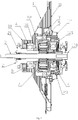
Fig. 1 is a structural sectional view ofembodiment 1 of the present disclosure; -
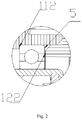
Fig. 2 is a partial enlarged view of Y ofFig. 1 ; -
Fig. 3 is a structural sectional view of embodiment 2 of the present disclosure; -
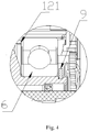
Fig. 4 is a partial enlarged view of K ofFig. 3 ; - Reference numerals in the
figures: 1 , bearing seat; 2, output shaft sleeve; 3, output shaft; 4, first bearing; 5, second bearing; 6, third bearing; 7, planet gear; 8, sun gear; 9, C-shaped check ring; 10, big oil seal; 11, first bearing seat; 12, second bearing seat; 21, inner barrel shaft; 22, brake wheel; 23, oil seal cover; 100, input shaft; 111, first locating surface; 112, second locating surface; 121, third locating surface; 122, fourth locating surface. - A further detailed description will be given below on specific embodiments of the present disclosure in combination with accompanying drawings.
- As shown in
Fig. 1 andFig. 2 , a decelerating clutch of a washing machine includes abearing seat 1, aninput shaft 100, an output shaft 3, and an output shaft sleeve 2, wherein theinput shaft 100 and the output shaft 3 are arranged coaxially, the output shaft sleeve 2 is sleeved on theinput shaft 100 and the output shaft 3, the output shaft sleeve 2 can rotate relative to theinput shaft 100, and the output shaft sleeve 2 is connected with theinput shaft 100 in a transmission manner via a planetary gear train. Preferably, theinput shaft 100 and the output shaft 3 are configured to a through-shaft, and they are of an integrated structure. Theinput shaft 100 is connected with a motor shaft, the output shaft 3 is connected with an impeller in an inner barrel, and the output shaft sleeve 2 is connected with an inner barrel to drive rotation of an inner barrel. The output shaft sleeve 2 is installed on abearing seat 1 via a bearing, and can rotate relative to thebearing seat 1, and thebearing seat 1 is configured to support the output shaft sleeve 2. At least one bearing is respectively arranged at two ends and a middle part of the output shaft sleeve 2, to form a three-point support, such that two ends and the middle part of the output shaft sleeve 2 are supported, and an inner ring of the bearing is coordinated with the output shaft sleeve 2, and an outer ring is coordinated with a bearing seat. - Specifically, the output shaft sleeve 2 includes an
inner barrel shaft 21, abrake wheel 22 and anoil seal cover 23, wherein theinner barrel shaft 21 and theoil seal cover 23 are respectively arranged at two sides of thebrake wheel 22, and are fixedly connected with thebrake wheel 22, and the three moves synchronously. Specifically, theinner barrel shaft 21 and thebrake wheel 22 are connected in an inserting manner, and are in interference fit, and theoil seal cover 23 is in riveted connection with thebrake wheel 22. Theinner barrel shaft 21 is fixedly connected with an inner barrel, a planetary gear train is set within abrake wheel 22, and includes asun gear 8 which is fixedly installed on aninput shaft 100 and aplanet gear 7 which is meshed with thesun gear 8 and installed on a planet carrier, teeth matched with theplanet gear 7 are arranged on an inner wall of thebrake wheel 22, or an outer tooth ring is fixedly arranged within thebrake wheel 22, an inner side of the outer tooth ring is meshed with theplanet gear 7, and thebrake wheel 22 can be driven to rotate through theplanet gear 7 when thesun gear 8 rotates. - The bearing includes: a first bearing 4 installed on the
inner barrel shaft 21, a second bearing shaft 5 installed on abrake wheel 22, and the third bearing 6 installed on anoil seal cover 23. An inner ring of the first bearing 4 and the third bearing 6 is respectively in interference fit with theinner barrel shaft 21 and theoil seal cover 23, and an outer ring is respectively in interference fit or clearance fit with thebearing seat 1. Since thebrake wheel 22 and theoil seal cover 23 are simultaneously supported by a bearing, when thebrake wheel 22 and theoil seal cover 23 are subjected to a radial load, the pressure is absorbed by the bearing, thereby preventing pressure from concentrating on a connecting point between thebrake wheel 22 and theoil seal cover 23, since concentrated pressure may cause cracking at a connecting point between thebrake wheel 22 and theoil seal cover 23. - The
inner barrel shaft 21 is a step shaft, and is provided with a step surface to be in location fit with the first bearing 4; an inner ring of the second bearing 5 is in clearance fit with an outer peripheral wall of thebrake wheel 22, and an outer ring is in interference fit with an inner wall of thebearing seat 1. Through such a setting manner, tiny radial movement of thebrake wheel 22 is allowed, when thebrake wheel 22 heats up, a certain deformation space is reserved for thebrake wheel 22, and meanwhile, assembly is facilitated. - The
bearing seat 1 includes afirst bearing seat 11 and asecond bearing seat 12, wherein thefirst bearing seat 11 is installed on an outer barrel, thefirst bearing seat 11 and thesecond bearing seat 12 are fixedly connected to form a mold cavity for accommodating the output shaft 3 and the output shaft sleeve 2, thebrake wheel 22 is arranged inside the mold cavity, and thefirst bearing seat 11 and the second bearingseat 12 are respectively provided with a locating structure for locating bearings. Wherein the first bearing 4 and the third bearing 6 are respectively separately located through the first bearingseat 11 and the second bearingseat 12, and the second bearing 5 is jointly located through locating structures which are coordinated with each other and which are arranged on the first bearingseat 11 and the second bearingseat 12. - Specifically, the first bearing
seat 11 is provided with a first locatingsurface 111 and a second locatingsurface 112, and the second bearingseat 12 is provided with a third locatingsurface 121 and a fourth locatingsurface 122; the first locatingsurface 111 is in location fit with the first bearing 4, to limit movement of the first bearing 4 towards one side of a motor; the third locatingsurface 121 is in location fit with the third bearing 6, to limit movement of the third bearing 6 towards one side of a motor. The second locatingsurface 112 and the fourth locatingsurface 122 are jointly in location fit with the second bearing 5, the second locatingsurface 112 is in contact fit with one end face of an outer ring of the second bearing 5, to limit movement of the second bearing 5 towards one side of an inner barrel, and the fourth locatingsurface 122 is in contact fit with another end face of the outer ring of the second bearing 5, to limit movement of the second bearing 5 towards one side of a motor. - Preferably, the first locating
surface 111 and the second locatingsurface 112 are step surfaces which are arranged on an inner wall of a first cavity of the first bearingseat 11, the third locatingsurface 121 is a step surface which is arranged on the second bearingseat 12, the fourth locatingsurface 122 is an end face of the second bearingseat 12, and an end part, on which the end face is located, of the second bearingseat 12, is inserted into the first cavity of thefirst bearing seat 11, such that the end face is arranged in the first cavity of a first bearingseat 11, and is arranged relative to the second locatingsurface 112. - Preferably, a tiny gap is reserved between an end face of the second bearing 5 and the fourth locating
surface 122, to allow tiny axial movement of the second bearing 5. - A
big oil seal 10 is further arranged between theinner barrel shaft 21 and the first bearingseat 11, an end cover is further arranged between the output shaft 3 and the second bearingseat 12, and a mold cavity which is formed between the first bearingseat 11 and the second bearingseat 12 is sealed, to prevent dust from entering the mold cavity. - In
embodiment 1, the output shaft sleeve 2 is not completely axially limited; therefore, the output shaft sleeve 2 may be enabled to move towards one side of an inner barrel. In combination withFig. 3 andFig. 4 , the present embodiment differs fromembodiment 1 as follows: the third locatingsurface 121 is arranged at one side, close to thebrake wheel 22, of the third bearing 6, and limits movement of the third bearing 6 towards one side of an inner barrel. Theoil seal cover 23 is clamped with a C-shaped check ring 9, and the C-shaped check ring 9 is arranged at another side of the third bearing 6 and is in location fit with the third bearing 6, to limit movement of the output shaft sleeve 2 towards one side of an inner barrel. When the output shaft sleeve 2 moves towards one side of a motor, the output shaft sleeve 2 will be limited by the first locatingsurface 111 on the first bearingseat 11, and when the output shaft sleeve 2 moves towards one side of an inner barrel, the output shaft sleeve 2 will be limited by the third locatingsurface 121 on the second bearingseat 12, such that the output shaft sleeve 2 is completely axially limited, thereby avoiding axial movement. - Those skilled in the art should also understand that, such terms as "left" and "right" used in embodiments of the present disclosure for indicating orientation or positional relationship are based on the status of accompanying drawings, and these terms are merely for the convenience of description and understanding of technical solutions of the present disclosure, rather than for indicating or implying that the device or element referred to must be located in a certain orientation or must be constructed or operated in a certain orientation, therefore the terms cannot be understood as a limitation to the present disclosure.
- What is described above is embodiments of the present disclosure. It should be noted that, for those skilled in the art, under a premise of not departing from principles of the present disclosure, various transformations and improvements can also be made, and such transformations and improvements shall also be deemed to fall within the protection scope of the present disclosure.
Claims (10)
- A decelerating clutch of a washing machine, comprising: a bearing seat, an input shaft, an output shaft, and an output shaft sleeve, wherein,
the input shaft and the output shaft are arranged coaxially, the output shaft sleeve is sleeved on the input shaft and the output shaft,
the output shaft sleeve is installed on the bearing seat via a bearing, the output shaft sleeve is connected with the input shaft in a transmission manner via a planetary gear train,
two ends and a middle part of the output shaft sleeve are respectively provided with at least one bearing,
an inner ring of the bearing is coordinated with the output shaft sleeve, and an outer ring is coordinated with the bearing seat. - The decelerating clutch of a washing machine of claim 1, wherein the output shaft sleeve comprises an inner barrel shaft, a brake wheel and an oil seal cover,
the inner barrel shaft and the oil seal cover are respectively arranged at two sides of the brake wheel and are fixedly connected with the brake wheel, and
the bearing comprises a first bearing installed on the inner barrel shaft, a second bearing installed on the brake wheel, and a third bearing installed on the oil seal cover. - The decelerating clutch of a washing machine of claim 2, wherein an inner ring of the second bearing is in clearance fit with an outer peripheral wall of the brake wheel, and an outer ring is in interference fit with an inner wall of the bearing seat.
- The decelerating clutch of a washing machine of claim 2 or 3, wherein the bearing seat comprises a first bearing seat and a second bearing seat,
the first bearing seat and the second bearing seat are fixedly connected to form a cavity for accommodating the output shaft and the output shaft sleeve, and
the first bearing seat and the second bearing seat are respectively provided with a locating structure for locating bearings. - The decelerating clutch of a washing machine of claim 4, wherein the first bearing seat and the second bearing seat are provided with locating structures which are coordinated with each other, for jointly defining axial movement of the second bearing.
- The decelerating clutch of a washing machine of claim 4, wherein a first locating surface and a second locating surface are arranged on the first bearing seat,
a third locating surface and a fourth locating surface are arranged on the second bearing seat;
the first locating surface is in location fit with the first bearing, the third locating surface is in location fit with the third bearing, and the second locating surface and the fourth locating surface are jointly in location fit with the second bearing. - The decelerating clutch of a washing machine of claim 6, wherein the second locating surface is in contact fit with one end face of an outer ring of the second bearing, and the fourth locating surface is in contact fit with another end face of the outer ring of the second bearing.
- The decelerating clutch of a washing machine of claim 7, wherein the second locating surface is a step surface arranged on an inner wall of a first cavity of the first bearing seat,
the fourth locating surface is an end face of the second bearing seat,
an end part, on which the end face is located, of the second bearing seat, is inserted into the first cavity of the first bearing seat, and
the end face is arranged in the first cavity of the first bearing seat and is arranged opposite to the second locating surface. - The decelerating clutch of a washing machine of claim 2, wherein the inner barrel shaft is a step shaft,
and is provided with a step surface to be in location fit with the first bearing; the oil seal cover is clamped with a C-shaped check ring,
and the C-shaped check ring is arranged at one side, far away from the inner barrel shaft, of a third bearing, and is in location fit with the third bearing. - A washing machine configured with the decelerating clutch of a washing machine of any of claims 1-9.
Applications Claiming Priority (2)
| Application Number | Priority Date | Filing Date | Title |
|---|---|---|---|
| CN201710150399.5A CN108570805B (en) | 2017-03-14 | 2017-03-14 | A washing machine deceleration clutch and washing machine |
| PCT/CN2018/078401 WO2018166397A1 (en) | 2017-03-14 | 2018-03-08 | Washing machine speed reducing clutch and washing machine |
Publications (4)
| Publication Number | Publication Date |
|---|---|
| EP3597811A1 true EP3597811A1 (en) | 2020-01-22 |
| EP3597811A4 EP3597811A4 (en) | 2020-03-04 |
| EP3597811C0 EP3597811C0 (en) | 2024-01-03 |
| EP3597811B1 EP3597811B1 (en) | 2024-01-03 |
Family
ID=63522753
Family Applications (1)
| Application Number | Title | Priority Date | Filing Date |
|---|---|---|---|
| EP18768331.3A Active EP3597811B1 (en) | 2017-03-14 | 2018-03-08 | Washing machine speed reducing clutch and washing machine |
Country Status (5)
| Country | Link |
|---|---|
| US (1) | US11525203B2 (en) |
| EP (1) | EP3597811B1 (en) |
| JP (1) | JP6936943B2 (en) |
| CN (1) | CN108570805B (en) |
| WO (1) | WO2018166397A1 (en) |
Families Citing this family (3)
| Publication number | Priority date | Publication date | Assignee | Title |
|---|---|---|---|---|
| WO2020147781A1 (en) * | 2019-01-16 | 2020-07-23 | 韩革新 | Transmission device for household electrical appliance |
| KR102667041B1 (en) * | 2019-08-14 | 2024-05-17 | 엘지전자 주식회사 | Driving part assembly and top-loader washer thereof |
| CN113969481A (en) * | 2020-07-24 | 2022-01-25 | 青岛海尔洗衣机有限公司 | Pulsator washing machine |
Family Cites Families (18)
| Publication number | Priority date | Publication date | Assignee | Title |
|---|---|---|---|---|
| JPH07299283A (en) * | 1994-05-02 | 1995-11-14 | Matsushita Electric Ind Co Ltd | Clutch switching device for dehydration washing machine |
| JP2000288290A (en) * | 1999-04-05 | 2000-10-17 | Ntn Corp | Fully automatic washing machine |
| CN1151596C (en) | 2000-07-12 | 2004-05-26 | 北京东方渴望科技发展有限公司 | Power directly-driving device for washing machine |
| KR100352066B1 (en) * | 2000-07-14 | 2002-09-11 | 삼성전자 주식회사 | Power transmission apparatus for washing machine |
| CN200992652Y (en) * | 2006-12-18 | 2007-12-19 | 陈伟农 | Decelerating clutch for fully-automatic washing machine |
| CN101205677A (en) * | 2006-12-18 | 2008-06-25 | 陈伟农 | Decelerating clutch for full-automatic washing machine |
| CN201089846Y (en) * | 2007-08-05 | 2008-07-23 | 浙江三星机电股份有限公司 | End face single wave oscillating tooth decelerator of washing machine slowing-down clutch |
| CN201406580Y (en) * | 2009-02-26 | 2010-02-17 | 浙江三星机电股份有限公司 | A new type of pulsator-type dual-power fully automatic washing machine deceleration clutch |
| JP2011200545A (en) | 2010-03-26 | 2011-10-13 | Toshiba Corp | Laundry apparatus |
| CN202380279U (en) * | 2011-12-22 | 2012-08-15 | 张国兴 | Sealing device for driving mechanism of double-power washing machine |
| CN202595505U (en) * | 2012-05-21 | 2012-12-12 | 浙江三星机电股份有限公司 | Bidirectional driving device of impeller type washing machine |
| CN103541184B (en) * | 2012-07-10 | 2017-05-10 | 安徽聚隆传动科技股份有限公司 | Siamese-type motor deceleration clutch of washing machine |
| CN203602913U (en) * | 2013-10-31 | 2014-05-21 | 杭州川崎精工机有限公司 | Dual-power washing machine reduction clutch |
| EP3103910A4 (en) * | 2014-01-22 | 2017-09-20 | Haier Group Corporation | Washing machine decelerating clutch and washing machine |
| JP6345974B2 (en) * | 2014-04-25 | 2018-06-20 | アクア株式会社 | Drum washing machine |
| KR101639023B1 (en) | 2015-01-26 | 2016-07-25 | 주식회사 아모텍 | Rdum driving apparatus, drum washing machine having the same and driving method thereof |
| CN204875241U (en) * | 2015-08-05 | 2015-12-16 | 浙江三星机电股份有限公司 | Novel clutch of drum type washing machine |
| CN105063965B (en) * | 2015-08-05 | 2017-05-10 | 浙江三星机电股份有限公司 | Clutch for roller washing machine |
-
2017
- 2017-03-14 CN CN201710150399.5A patent/CN108570805B/en active Active
-
2018
- 2018-03-08 WO PCT/CN2018/078401 patent/WO2018166397A1/en not_active Ceased
- 2018-03-08 JP JP2019550684A patent/JP6936943B2/en active Active
- 2018-03-08 EP EP18768331.3A patent/EP3597811B1/en active Active
- 2018-03-08 US US16/494,051 patent/US11525203B2/en active Active
Also Published As
| Publication number | Publication date |
|---|---|
| EP3597811C0 (en) | 2024-01-03 |
| JP6936943B2 (en) | 2021-09-22 |
| CN108570805B (en) | 2020-08-18 |
| US11525203B2 (en) | 2022-12-13 |
| CN108570805A (en) | 2018-09-25 |
| US20210123179A1 (en) | 2021-04-29 |
| EP3597811A4 (en) | 2020-03-04 |
| WO2018166397A1 (en) | 2018-09-20 |
| EP3597811B1 (en) | 2024-01-03 |
| JP2020512075A (en) | 2020-04-23 |
Similar Documents
| Publication | Publication Date | Title |
|---|---|---|
| EP3597810B1 (en) | Washing machine decelerating clutch and washing machine | |
| CN105599591B (en) | Wheel hub drive assembly | |
| US11525203B2 (en) | Decelerating clutch of a washing machine, and washing machine | |
| CN105691184A (en) | Wheel hub driving assembly | |
| US8251861B2 (en) | Planetary wheel end with piloted sun gear shaft | |
| KR20150005555A (en) | Construction machine drive device | |
| WO2016082633A1 (en) | Wheel hub drive assembly | |
| CN103321018A (en) | Direct-drive clutch of washing machine | |
| KR101930763B1 (en) | Actuator for electronic parking brake | |
| CN103321017A (en) | Dual-power direct-drive clutch of washing machine | |
| CN102011857A (en) | Novel speed reducer with torsion limitation function | |
| CN105691104A (en) | Hub driving assembly | |
| CN101705979B (en) | Cycloid-pin wheel speed reducer | |
| CN101517258B (en) | mechanical torque converter | |
| CN214197047U (en) | Transmission shaft electric device with brake assembly | |
| CN206785937U (en) | a gear box | |
| CN109019444B (en) | Connecting device for transmitting power | |
| CN208651476U (en) | A kind of multimode clutch | |
| CN211951273U (en) | A structure to prevent radial movement of gears | |
| CN110953272B (en) | A structure to prevent radial movement of gears | |
| CN108944394A (en) | Electric car and its integrated dynamic assembly | |
| CN211032156U (en) | Transmission device of forklift transmission | |
| CN106989176A (en) | A kind of robot flip side assembling device | |
| CN222163417U (en) | A wheel-side reduction structure | |
| CN104420129A (en) | Washing machine integration motor acceleration clutch |
Legal Events
| Date | Code | Title | Description |
|---|---|---|---|
| STAA | Information on the status of an ep patent application or granted ep patent |
Free format text: STATUS: THE INTERNATIONAL PUBLICATION HAS BEEN MADE |
|
| PUAI | Public reference made under article 153(3) epc to a published international application that has entered the european phase |
Free format text: ORIGINAL CODE: 0009012 |
|
| STAA | Information on the status of an ep patent application or granted ep patent |
Free format text: STATUS: REQUEST FOR EXAMINATION WAS MADE |
|
| 17P | Request for examination filed |
Effective date: 20191014 |
|
| AK | Designated contracting states |
Kind code of ref document: A1 Designated state(s): AL AT BE BG CH CY CZ DE DK EE ES FI FR GB GR HR HU IE IS IT LI LT LU LV MC MK MT NL NO PL PT RO RS SE SI SK SM TR |
|
| AX | Request for extension of the european patent |
Extension state: BA ME |
|
| A4 | Supplementary search report drawn up and despatched |
Effective date: 20200205 |
|
| RIC1 | Information provided on ipc code assigned before grant |
Ipc: D06F 37/40 20060101AFI20200130BHEP |
|
| DAV | Request for validation of the european patent (deleted) | ||
| DAX | Request for extension of the european patent (deleted) | ||
| STAA | Information on the status of an ep patent application or granted ep patent |
Free format text: STATUS: EXAMINATION IS IN PROGRESS |
|
| 17Q | First examination report despatched |
Effective date: 20220503 |
|
| GRAP | Despatch of communication of intention to grant a patent |
Free format text: ORIGINAL CODE: EPIDOSNIGR1 |
|
| STAA | Information on the status of an ep patent application or granted ep patent |
Free format text: STATUS: GRANT OF PATENT IS INTENDED |
|
| INTG | Intention to grant announced |
Effective date: 20230725 |
|
| RAP1 | Party data changed (applicant data changed or rights of an application transferred) |
Owner name: HAIER SMART HOME CO., LTD. Owner name: QINGDAO JIAONAN HAIER WASHING MACHINE CO., LTD. |
|
| GRAS | Grant fee paid |
Free format text: ORIGINAL CODE: EPIDOSNIGR3 |
|
| GRAA | (expected) grant |
Free format text: ORIGINAL CODE: 0009210 |
|
| STAA | Information on the status of an ep patent application or granted ep patent |
Free format text: STATUS: THE PATENT HAS BEEN GRANTED |
|
| AK | Designated contracting states |
Kind code of ref document: B1 Designated state(s): AL AT BE BG CH CY CZ DE DK EE ES FI FR GB GR HR HU IE IS IT LI LT LU LV MC MK MT NL NO PL PT RO RS SE SI SK SM TR |
|
| REG | Reference to a national code |
Ref country code: GB Ref legal event code: FG4D |
|
| REG | Reference to a national code |
Ref country code: DE Ref legal event code: R096 Ref document number: 602018063637 Country of ref document: DE |
|
| REG | Reference to a national code |
Ref country code: CH Ref legal event code: EP |
|
| REG | Reference to a national code |
Ref country code: IE Ref legal event code: FG4D |
|
| U01 | Request for unitary effect filed |
Effective date: 20240118 |
|
| U07 | Unitary effect registered |
Designated state(s): AT BE BG DE DK EE FI FR IT LT LU LV MT NL PT SE SI Effective date: 20240126 |
|
| PG25 | Lapsed in a contracting state [announced via postgrant information from national office to epo] |
Ref country code: ES Free format text: LAPSE BECAUSE OF FAILURE TO SUBMIT A TRANSLATION OF THE DESCRIPTION OR TO PAY THE FEE WITHIN THE PRESCRIBED TIME-LIMIT Effective date: 20240103 |
|
| PG25 | Lapsed in a contracting state [announced via postgrant information from national office to epo] |
Ref country code: ES Free format text: LAPSE BECAUSE OF FAILURE TO SUBMIT A TRANSLATION OF THE DESCRIPTION OR TO PAY THE FEE WITHIN THE PRESCRIBED TIME-LIMIT Effective date: 20240103 |
|
| PG25 | Lapsed in a contracting state [announced via postgrant information from national office to epo] |
Ref country code: IS Free format text: LAPSE BECAUSE OF FAILURE TO SUBMIT A TRANSLATION OF THE DESCRIPTION OR TO PAY THE FEE WITHIN THE PRESCRIBED TIME-LIMIT Effective date: 20240503 |
|
| PG25 | Lapsed in a contracting state [announced via postgrant information from national office to epo] |
Ref country code: GR Free format text: LAPSE BECAUSE OF FAILURE TO SUBMIT A TRANSLATION OF THE DESCRIPTION OR TO PAY THE FEE WITHIN THE PRESCRIBED TIME-LIMIT Effective date: 20240404 |
|
| PG25 | Lapsed in a contracting state [announced via postgrant information from national office to epo] |
Ref country code: RS Free format text: LAPSE BECAUSE OF FAILURE TO SUBMIT A TRANSLATION OF THE DESCRIPTION OR TO PAY THE FEE WITHIN THE PRESCRIBED TIME-LIMIT Effective date: 20240403 Ref country code: HR Free format text: LAPSE BECAUSE OF FAILURE TO SUBMIT A TRANSLATION OF THE DESCRIPTION OR TO PAY THE FEE WITHIN THE PRESCRIBED TIME-LIMIT Effective date: 20240103 |
|
| PG25 | Lapsed in a contracting state [announced via postgrant information from national office to epo] |
Ref country code: CZ Free format text: LAPSE BECAUSE OF FAILURE TO SUBMIT A TRANSLATION OF THE DESCRIPTION OR TO PAY THE FEE WITHIN THE PRESCRIBED TIME-LIMIT Effective date: 20240103 |
|
| PG25 | Lapsed in a contracting state [announced via postgrant information from national office to epo] |
Ref country code: RS Free format text: LAPSE BECAUSE OF FAILURE TO SUBMIT A TRANSLATION OF THE DESCRIPTION OR TO PAY THE FEE WITHIN THE PRESCRIBED TIME-LIMIT Effective date: 20240403 Ref country code: NO Free format text: LAPSE BECAUSE OF FAILURE TO SUBMIT A TRANSLATION OF THE DESCRIPTION OR TO PAY THE FEE WITHIN THE PRESCRIBED TIME-LIMIT Effective date: 20240403 Ref country code: IS Free format text: LAPSE BECAUSE OF FAILURE TO SUBMIT A TRANSLATION OF THE DESCRIPTION OR TO PAY THE FEE WITHIN THE PRESCRIBED TIME-LIMIT Effective date: 20240503 Ref country code: HR Free format text: LAPSE BECAUSE OF FAILURE TO SUBMIT A TRANSLATION OF THE DESCRIPTION OR TO PAY THE FEE WITHIN THE PRESCRIBED TIME-LIMIT Effective date: 20240103 Ref country code: GR Free format text: LAPSE BECAUSE OF FAILURE TO SUBMIT A TRANSLATION OF THE DESCRIPTION OR TO PAY THE FEE WITHIN THE PRESCRIBED TIME-LIMIT Effective date: 20240404 Ref country code: CZ Free format text: LAPSE BECAUSE OF FAILURE TO SUBMIT A TRANSLATION OF THE DESCRIPTION OR TO PAY THE FEE WITHIN THE PRESCRIBED TIME-LIMIT Effective date: 20240103 |
|
| PG25 | Lapsed in a contracting state [announced via postgrant information from national office to epo] |
Ref country code: PL Free format text: LAPSE BECAUSE OF FAILURE TO SUBMIT A TRANSLATION OF THE DESCRIPTION OR TO PAY THE FEE WITHIN THE PRESCRIBED TIME-LIMIT Effective date: 20240103 |
|
| PG25 | Lapsed in a contracting state [announced via postgrant information from national office to epo] |
Ref country code: PL Free format text: LAPSE BECAUSE OF FAILURE TO SUBMIT A TRANSLATION OF THE DESCRIPTION OR TO PAY THE FEE WITHIN THE PRESCRIBED TIME-LIMIT Effective date: 20240103 |
|
| REG | Reference to a national code |
Ref country code: DE Ref legal event code: R097 Ref document number: 602018063637 Country of ref document: DE |
|
| PG25 | Lapsed in a contracting state [announced via postgrant information from national office to epo] |
Ref country code: SM Free format text: LAPSE BECAUSE OF FAILURE TO SUBMIT A TRANSLATION OF THE DESCRIPTION OR TO PAY THE FEE WITHIN THE PRESCRIBED TIME-LIMIT Effective date: 20240103 |
|
| PG25 | Lapsed in a contracting state [announced via postgrant information from national office to epo] |
Ref country code: SK Free format text: LAPSE BECAUSE OF FAILURE TO SUBMIT A TRANSLATION OF THE DESCRIPTION OR TO PAY THE FEE WITHIN THE PRESCRIBED TIME-LIMIT Effective date: 20240103 |
|
| PG25 | Lapsed in a contracting state [announced via postgrant information from national office to epo] |
Ref country code: SM Free format text: LAPSE BECAUSE OF FAILURE TO SUBMIT A TRANSLATION OF THE DESCRIPTION OR TO PAY THE FEE WITHIN THE PRESCRIBED TIME-LIMIT Effective date: 20240103 Ref country code: SK Free format text: LAPSE BECAUSE OF FAILURE TO SUBMIT A TRANSLATION OF THE DESCRIPTION OR TO PAY THE FEE WITHIN THE PRESCRIBED TIME-LIMIT Effective date: 20240103 Ref country code: RO Free format text: LAPSE BECAUSE OF FAILURE TO SUBMIT A TRANSLATION OF THE DESCRIPTION OR TO PAY THE FEE WITHIN THE PRESCRIBED TIME-LIMIT Effective date: 20240103 |
|
| REG | Reference to a national code |
Ref country code: CH Ref legal event code: PL |
|
| PLBE | No opposition filed within time limit |
Free format text: ORIGINAL CODE: 0009261 |
|
| STAA | Information on the status of an ep patent application or granted ep patent |
Free format text: STATUS: NO OPPOSITION FILED WITHIN TIME LIMIT |
|
| U90 | Renewal fees not paid: noting of loss of rights |
Free format text: RENEWAL FEE NOT PAID FOR YEAR 07 Effective date: 20241016 |
|
| PG25 | Lapsed in a contracting state [announced via postgrant information from national office to epo] |
Ref country code: MC Free format text: LAPSE BECAUSE OF FAILURE TO SUBMIT A TRANSLATION OF THE DESCRIPTION OR TO PAY THE FEE WITHIN THE PRESCRIBED TIME-LIMIT Effective date: 20240103 |
|
| PG25 | Lapsed in a contracting state [announced via postgrant information from national office to epo] |
Ref country code: MC Free format text: LAPSE BECAUSE OF FAILURE TO SUBMIT A TRANSLATION OF THE DESCRIPTION OR TO PAY THE FEE WITHIN THE PRESCRIBED TIME-LIMIT Effective date: 20240103 |
|
| 26N | No opposition filed |
Effective date: 20241007 |
|
| GBPC | Gb: european patent ceased through non-payment of renewal fee |
Effective date: 20240403 |
|
| PG25 | Lapsed in a contracting state [announced via postgrant information from national office to epo] |
Ref country code: GB Free format text: LAPSE BECAUSE OF NON-PAYMENT OF DUE FEES Effective date: 20240403 |
|
| PG25 | Lapsed in a contracting state [announced via postgrant information from national office to epo] |
Ref country code: IE Free format text: LAPSE BECAUSE OF NON-PAYMENT OF DUE FEES Effective date: 20240308 |
|
| PG25 | Lapsed in a contracting state [announced via postgrant information from national office to epo] |
Ref country code: IE Free format text: LAPSE BECAUSE OF NON-PAYMENT OF DUE FEES Effective date: 20240308 Ref country code: GB Free format text: LAPSE BECAUSE OF NON-PAYMENT OF DUE FEES Effective date: 20240403 Ref country code: CH Free format text: LAPSE BECAUSE OF NON-PAYMENT OF DUE FEES Effective date: 20240331 |
|
| U93 | Unitary patent lapsed |
Free format text: RENEWAL FEE NOT PAID Effective date: 20240331 |
|
| PG25 | Lapsed in a contracting state [announced via postgrant information from national office to epo] |
Ref country code: CY Free format text: LAPSE BECAUSE OF FAILURE TO SUBMIT A TRANSLATION OF THE DESCRIPTION OR TO PAY THE FEE WITHIN THE PRESCRIBED TIME-LIMIT; INVALID AB INITIO Effective date: 20180308 |
|
| PG25 | Lapsed in a contracting state [announced via postgrant information from national office to epo] |
Ref country code: HU Free format text: LAPSE BECAUSE OF FAILURE TO SUBMIT A TRANSLATION OF THE DESCRIPTION OR TO PAY THE FEE WITHIN THE PRESCRIBED TIME-LIMIT; INVALID AB INITIO Effective date: 20180308 |
|
| PG25 | Lapsed in a contracting state [announced via postgrant information from national office to epo] |
Ref country code: TR Free format text: LAPSE BECAUSE OF FAILURE TO SUBMIT A TRANSLATION OF THE DESCRIPTION OR TO PAY THE FEE WITHIN THE PRESCRIBED TIME-LIMIT Effective date: 20240103 |