EP3597588A1 - Flurförderzeug mit einem hydraulischen system sowie verfahren zum betreiben eines hydraulischen systems - Google Patents
Flurförderzeug mit einem hydraulischen system sowie verfahren zum betreiben eines hydraulischen systems Download PDFInfo
- Publication number
- EP3597588A1 EP3597588A1 EP19185823.2A EP19185823A EP3597588A1 EP 3597588 A1 EP3597588 A1 EP 3597588A1 EP 19185823 A EP19185823 A EP 19185823A EP 3597588 A1 EP3597588 A1 EP 3597588A1
- Authority
- EP
- European Patent Office
- Prior art keywords
- mast
- lifting
- lowering
- free
- valve
- Prior art date
- Legal status (The legal status is an assumption and is not a legal conclusion. Google has not performed a legal analysis and makes no representation as to the accuracy of the status listed.)
- Granted
Links
Images


Classifications
-
- B—PERFORMING OPERATIONS; TRANSPORTING
- B66—HOISTING; LIFTING; HAULING
- B66F—HOISTING, LIFTING, HAULING OR PUSHING, NOT OTHERWISE PROVIDED FOR, e.g. DEVICES WHICH APPLY A LIFTING OR PUSHING FORCE DIRECTLY TO THE SURFACE OF A LOAD
- B66F9/00—Devices for lifting or lowering bulky or heavy goods for loading or unloading purposes
- B66F9/06—Devices for lifting or lowering bulky or heavy goods for loading or unloading purposes movable, with their loads, on wheels or the like, e.g. fork-lift trucks
- B66F9/075—Constructional features or details
- B66F9/20—Means for actuating or controlling masts, platforms, or forks
- B66F9/22—Hydraulic devices or systems
Definitions
- the invention relates to an industrial truck with a lifting mast with at least one mast lifting stage driven by at least one mast lifting cylinder and with a free lifting stage driven by at least one free lifting cylinder, with which a load suspension device can be moved along the lifting mast, comprising a hydraulic system for supplying the at least one mast lifting cylinder and the at least one a free lift cylinder with a hydraulic fluid. Furthermore, the invention relates to a method for operating a hydraulic system of an industrial truck with a lifting mast with at least one mast lifting stage and with a free lifting stage with which a load suspension device can be moved along the lifting mast, the hydraulic system comprising at least one mast lifting cylinder for driving the at least one mast lifting stage and at least comprises a free lift cylinder for driving the free lift stage.
- Industrial trucks such as forklifts, have many via a lifting mast with one or more mast lifting stages that are hydraulically operated by one or more mast lifting cylinders.
- the lifting mast comprises a standing mast permanently connected to the vehicle and usually two mast lifting stages, a central mast and an inner mast, which are extended by a mast lifting cylinder.
- a free lift cylinder moves a free lift stage with which a load suspension device, for example a lifting fork or the like, can be moved along the inner mast of the lifting mast.
- the free lift stage moves the barrel lifting device along this mast step and allows the operator of the industrial truck to move the load lifting device in height without the lifting mast being extended and thus changing the overall height of the industrial truck.
- an industrial truck with a lifting mast which comprises a hydraulic system for supplying at least one mast lifting cylinder and at least one free lifting cylinder, which is set up in such a way that the at least one mast lifting cylinder and the at least one free lifting cylinder in load lifting operation and / or can be operated simultaneously in load lowering mode. It is thus possible for the mast lift stages and the free lift stage to be retracted and / or extended at the same time.
- the lifting and lowering times of the load handler can be significantly reduced by the synchronous actuation of the mast lifting stages and the free lifting stage.
- an industrial truck with a lifting mast with at least one mast lifting stage driven by at least one mast lifting cylinder and with a free lifting stage driven by at least one free lifting cylinder, with which a load suspension device can be moved along the lifting mast, comprising a hydraulic system for supplying the at least one mast lifting cylinder and of the at least one free lift cylinder with a hydraulic fluid, this industrial truck being further developed in that the hydraulic system is set up to at least temporarily actuate the at least one mast lift cylinder and the at least one free lift cylinder in the load lifting mode and / or in the load lowering mode, the hydraulic system for relieving the load comprises at least one mast lift cylinder and the at least one free lift cylinder in the load lowering mode a first hydraulic return line and a second hydraulic return line and the first and the second hydraulis che return line are fluidly coupled to one another via a third connecting line, in which a third lowering valve is integrated.
- the known problem that the mast lift stage (s) is / are still extended after the lowering process is advantageously eliminated while the load suspension device is already in the area of the free lift.
- the possibility is created to restore the original order of free lift and mast lift, that is, a stroke sequence.
- the lowering time can be reduced by synchronously lowering the mast lift levels and the free lift level, thus increasing the handling capacity of the industrial truck.
- the headroom of the industrial truck is not unnecessarily restricted. If, as already mentioned above, the lowering process is not completely finished, ie not down to the lower one End position of the load handler performed because z. B. a load is to be transported, there is the possibility that the mast still protrudes beyond the height of the mast and thus unnecessarily limits the clearance height of the truck. This disadvantage is eliminated by restoring the original stroke sequence.
- fluidically coupled is understood to mean a hydraulically effective connection between the elements that are fluidically coupled to one another.
- the third connecting line connects the first and the second hydraulic return line to one another. There is no need for a direct connection. A hydraulically effective connection of these two return lines is sufficient.
- a hydraulic connecting line via which the first hydraulic return line is fluidly coupled to the third connecting line and the third lowering valve, and a further hydraulic connecting line, via which the second hydraulic return line is fluidly coupled to the third connecting line and the third lowering valve is free of installation.
- the industrial truck is further developed in that a control is provided which is set up to actuate the third lowering valve, so that when the third lowering valve is open, a stroke sequence between the at least one mast lifting stage driven by the at least one mast lifting cylinder and that of the at least one free lift cylinder driven free lift stage can be restored.
- the at least one mast lifting cylinder and the at least one free lifting cylinder are actuated simultaneously in the load lowering mode. This makes it possible to retract the mast lift stages and the free lift stage at the same time, which significantly reduces the lowering time of the load handler.
- the third lowering valve By actuating the third lowering valve, the basically desired stroke sequence can be restored, so that on the one hand a quick lowering process is possible and on the other hand the mast steps do not protrude unnecessarily high above the industrial truck.
- the at least one mast lifting stage can be retracted and the clearance height of the industrial truck is again the height predetermined by the height of the lifting frame.
- the headroom of the industrial truck is no longer unnecessarily higher than it is due to the design.
- actuation of the third lowering valve is understood to mean that it is opened or closed and, if appropriate, the flow rate is also controlled or regulated.
- the third lowering valve is, for example, an S / W valve, that is to say a binary-acting switching valve which only provides the switching positions open or closed, or alternatively a proportional valve.
- a first lowering valve is integrated in the first return line and a second lowering valve is integrated in the second return line, wherein the controller is further configured to control the first to third lowering valves in such a way that the first and second lowering valves are kept closed when that third lowering valve is actuated.
- first hydraulic return line runs between the at least one free lift cylinder and a reservoir for the hydraulic fluid and the second hydraulic return line runs between the at least one mast lift cylinder and this reservoir.
- the lowering valves are, for example, proportional valves.
- control is also set up to control the first lowering valve and the second lowering valve during a lowering process of the load suspension device in such a way that the mast lift stage and the free lift stage are retracted simultaneously and the load suspension device is lowered at the end of this lowering process of the load suspension device to close the first and the second lowering valve and then to open the third lowering valve, so that the stroke sequence between the at least one mast lifting stage and the free lifting stage can be restored, in particular the load suspension device being above a lower end position at the end of the lowering process.
- the free lift cylinder has a first cross section and the mast lift cylinder has a second cross section, the first and the second cross section being selected such that when the third lowering valve is open, the mast lift stage driven by the mast lift cylinder retracts at at least approximately the same speed , with which the free lift stage driven by the at least one free lift cylinder extends so that the load suspension means remains at least approximately at the same level.
- the mast lift cylinder usually has a higher pressure level than the free lift cylinder. Hydraulic fluid can flow from the mast lift cylinder into the free lift cylinder through the opening of the third lowering valve until the mast lift is completely retracted. If the hydraulically effective cross-sections of the lifting cylinders are selected as indicated, which can be achieved by simple practical tests, the mast lift moves in at the same speed as the free lift extends. These two speeds on the load handler add up to zero, which means that the load handler does not change its height. As a result, the mast lift can be fully retracted while the load handler does not change its height.
- an overflow of hydraulic fluid between the mast lift and the free lift ie an actuation of the third lowering valve by the control, is only provided if the load suspension device has not been completely retracted, that is to say is not in its lower end position. Furthermore, a corresponding control is only provided if the mast lift stage (s) is / are not completely retracted.
- the free lift cylinder has a first cross section and the mast lift cylinder has a second cross section
- the third lowering valve being a proportional valve and the controller being set up to control a hydraulic pump in dependence on a position of the third lowering valve in such a way that by the additional hydraulic fluid supplied to the hydraulic system of the hydraulic system, which extends the free lift stage driven by the at least one free lift cylinder at at least approximately the same speed as the mast lift stage driven by the at least one mast lift cylinder, so that the load suspension means remains at least approximately at the same level.
- the hydraulic pump is controlled or regulated depending on the position of the proportional valve.
- the hydraulic pump delivers the required amount of hydraulic fluid in order to restore the stroke sequence of the mast stages in a controlled manner.
- the free lift cylinder has a first cross section and the mast lift cylinder has a second cross section
- the third lowering valve being a proportional valve and the control unit being set up to control, depending on a detected position of the load suspension means, that by the hydraulic pump supplied additional hydraulic fluid which extends the free lift stage driven by the at least one free lift cylinder at at least approximately the same speed at which the mast lift stage driven by the at least one mast lift cylinder moves in, so that the load suspension means remains at least approximately at the same level.
- the hydraulic pump is controlled or regulated as a function of a position of the load-carrying device that is detected with the aid of a sensor.
- the first and second cross sections are in particular of different sizes.
- the industrial truck is further developed in that the hydraulic system is set up in such a way that the third lowering valve acts as a lifting valve in the load lifting mode and as a lowering valve in the load lowering mode.
- the third lowering valve thus advantageously has a double function.
- the hydraulic system can be simplified in terms of design, for example a lifting valve can be dispensed with, since the third lowering valve takes over this function in lifting operation.
- the industrial truck is further developed in that the hydraulic system for supplying the at least one mast lifting cylinder and the at least one free lifting cylinder with hydraulic fluid comprises a hydraulic pump which is set up to operate the free lifting cylinder via a first supply branch and the mast lifting cylinder via a second supply branch to be pressurized with hydraulic fluid under pressure, the third lowering valve being integrated in the first or the second supply branch, and in particular a check valve being present in a connecting line between the hydraulic pump and the third lowering valve.
- only a check valve is provided on the pressure side of the hydraulic pump.
- the two supply branches open into a common supply line in which the hydraulic pump is integrated.
- the check valve is especially in this common supply line.
- the object is further achieved by a method for operating a hydraulic system of an industrial truck with a lifting mast with at least one mast lifting stage and with a free lifting stage with which a load suspension device can be moved along the lifting mast, the hydraulic system having at least one mast lifting cylinder for driving the at least one mast lifting stage and comprises at least one free lift cylinder for driving the free lift stage, which is further developed in that the hydraulic system actuates the at least one mast lift cylinder and the at least one free lift cylinder at least temporarily at the same time in the load lifting operation and / or in the load lowering operation, the hydraulic system for relieving the at least one mast lifting cylinder and the at least one free stroke cylinder in the load lowering mode comprises a first hydraulic return line and a second hydraulic return line, and wherein the first and the second hydraulic return line are fluidis via a third lowering valve ch are coupled to one another, the hydraulic system comprising a control with which the third lowering valve is operated such that the first and second hydraulic return lines are fluidly coupled to one another via the third lowering valve.
- the method is developed in particular in that the third lowering valve is opened by a stroke sequence between the mast stroke stage driven by the at least one mast lift cylinder and the free stroke stage driven by the at least one free stroke cylinder restore.
- a first lowering valve is integrated in the first return line and a second lowering valve is integrated in the second return line, the control unit controlling the first to third lowering valves in such a way that the first and second lowering valves are kept closed when that third lowering valve is actuated.
- the method is further developed, in particular, in that the controller controls the first lowering valve and the second lowering valve during a lowering process of the load suspension device in such a way that the mast lift stage and the free lift stage are retracted simultaneously and the load suspension device is lowered, at the end of this lowering process of the load suspension device the first and the second lowering valve are closed and then the third lowering valve is opened so that the stroke sequence between the at least one mast lifting stage and the free lifting stage is restored, in particular the load suspension device being at the end of the lowering process above a lower end position.
- the method is advantageously further developed in that, when the third lowering valve is open, the mast lift stage driven by the mast lift cylinder retracts at least approximately the same speed as the free lift stage driven by the at least one free lift cylinder, so that the load suspension means remains at least approximately at the same height.
- the free lift cylinder has a first cross section and the mast lift cylinder has a second cross section
- the third lowering valve a proportional valve and the control unit controls a hydraulic pump in such a manner as a function of a position of the third lowering valve and / or as a function of a detected position of the load-carrying means that additional hydraulic fluid supplied to the hydraulic system by the hydraulic pump controls the free stroke level driven by the at least one free stroke cylinder with at least approximately the same speed extends with which the mast lift stage driven by the at least one mast lift cylinder retracts, so that the load suspension means remains at least approximately at the same height.
- the method is further developed in that the third lowering valve acts as a lifting valve in load lifting operation and as a lowering valve in load lowering operation.
- the third lowering valve thus advantageously fulfills a double function.
- Embodiments according to the invention can fulfill individual features or a combination of several features.
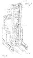
- Fig. 1 shows an industrial truck 2, for example a forklift, with a lifting mast 4, comprising, for example, a first mast lifting stage 41, the inner mast, and a second mast lifting stage 42, the middle mast.
- the mast 4 is one in Fig. 1 Mast lift cylinder, not shown (several mast lift cylinders can also be provided).
- the lifting mast 4 comprises a standing mast 54 which is firmly connected to the vehicle frame of the industrial truck 2 (cf. also FIG. 4 ).
- the maximum height of the mast 54 limits the design-related headroom of the industrial truck 2.
- the middle mast that is to say the second mast lifting stage 42, is driven, for example, by the mast lifting cylinder.
- the inner mast that is to say the first mast lifting stage 41, is also coupled, for example, to the central mast via a chain, so that these two extending masts extend simultaneously.
- the industrial truck 2 further comprises a free lift stage with which a load suspension device 6, for example a load suspension fork, can be moved along the inner mast, that is to say along the first mast lift stage 41.
- the free lift stage comprises a free lift cylinder 8.
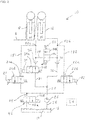
- Fig. 2 shows a schematic circuit diagram of a hydraulic system 10 as it is integrated in the industrial truck 2 according to one embodiment.
- the hydraulic system 10 serves to supply a mast lifting cylinder 12 and the free lifting cylinder 8 with which the load suspension device 6 is moved with a hydraulic fluid 14.
- the hydraulic fluid 14 is removed from a storage container 16 and also supplied to it again.
- the hydraulic system 10 is set up to at least temporarily operate the mast lifting cylinder 12 and the free lifting cylinder 8 simultaneously in the load lifting mode and / or in the load lowering mode.
- the hydraulic system 10 comprises separate hydraulic return lines, namely a first hydraulic return line 181 and a second hydraulic return line 182.
- the first hydraulic return line 181 runs between the free lift cylinder 8 and the storage container 16.
- the second hydraulic return line 182 runs between the mast lifting cylinder 12 and the storage container 16.
- the first and the second hydraulic return line 181, 182 are brought together on the pressure side of a common hydraulic return line 44.
- a common lowering valve 46 is integrated in the common hydraulic return line 44.
- a first lowering valve 21 is integrated in the first hydraulic return line 181 and a second lowering valve 22 is integrated in the second hydraulic return line 182.
- the lowering valves 21, 22, like the common lowering valve 46, are, for example, proportional valves.
- the first and the second lowering valve 21, 22 can be switched between a first switching position 21a, 22a, in which the lowering valves 21, 22 work as check valves, and a second switching position 21b, 22b.
- the lowering valves 21, 22 are set up to be a first Volume flow or a second volume flow to control or regulate.
- the first lowering valve 21 controls or regulates a first volume flow through the first hydraulic return line 181
- the second lowering valve 22 controls or regulates a second volume flow through the second hydraulic return line 182.
- the first and second lowering valves 21, 22 are each proportional valves.
- the lowering valves 21, 22 can be controlled separately from one another.
- a control 24 is included in the hydraulic system 10, which controls the two lowering valves 21, 22 via connecting lines (not shown for reasons of clarity).
- the common lowering valve 46 also comprises a first switching position 46a, in which it acts as a shut-off valve, and a second switching position 46b, in which the common lowering valve 46 is set up to control or regulate a third volume flow.
- the controller 24 is set up or provided with software means that the lowering valves 21, 22 open simultaneously in a load-lowering operation, ie when the load-carrying means 6 is lowered.
- the free lift cylinder 8 of the free lift stage and the mast lift cylinder of the mast lift stages 41, 42 are retracted simultaneously.
- the load suspension device 6 actuated by the free lift stage drops along the first mast lift stage 41, while the lift mast 4, ie the first and the second mast lift stage 41, 42, retract at the same time. In other words, synchronous retraction takes place of the two mast lifting stages 41, 42 and lowering of the load suspension device 6.
- the hydraulic system 10 of the industrial truck 2 comprises a hydraulic pump 26. This takes hydraulic fluid 14 from the reservoir 16 via a hydraulic feed line 28.
- the hydraulic pump 26 is integrated into the hydraulic feed line 28. In the load lifting mode, the hydraulic pump 26 serves to apply hydraulic fluid 14 to the mast lifting cylinder 12 and the free lifting cylinder 8.
- the hydraulic feed line 28 bifurcates between the hydraulic pump 26, the free lift cylinder 8 and the mast lift cylinder 12 into a first supply branch 31 and into a second supply branch 32.
- the first supply branch 31 leads to the free lift cylinder 8
- the second supply branch 32 leads to the mast lift cylinder 12.
- a lift valve 34 is integrated, which can be designed as a proportional valve.
- the lift valve 34 like the hydraulic pump 26, can be controlled or regulated via the controller 24.
- the lifting valve 34 comprises a first switching position 34a, in which the lifting valve 34 acts as a shut-off valve, and a second switching position 34b, in which the lifting valve 34 operates as a proportional valve.
- the first hydraulic return line 181 and the second hydraulic return line 182 are fluidly coupled to one another via a third connecting line 48, into which a third lowering valve 50 is integrated.
- the circuit diagram shown shows the third connecting line 48 between the first supply branch 31 and the second supply branch 32 of the supply line 28.
- the first and the second supply branch 31, 32 are on the first and second nodes 52a, 52b are connected to the first hydraulic return line 181 and the second hydraulic return line 182, respectively.
- the connection shown is hydraulically equivalent to a direct connection of the first and second hydraulic return lines 181, 182 through the third connection line 48.
- the controller 24 is set up to actuate the third lowering valve 50 of the hydraulic system 10, ie to open, close it or to control or regulate a flow.
- the third lowering valve 50 can be, for example, a binary-acting switching valve which only provides the switching positions open or closed, or alternatively a proportional valve. Is only an example in Fig. 2 a proportional valve is shown.
- a fluidic connection between the mast lifting cylinder 12 and the free lifting cylinder 8 can thus be established.
- the controller 24 is also configured to keep the first and second lowering valves 21, 22 closed when the third lowering valve 50 is actuated. A backflow of the hydraulic fluid is also prevented by the check valves 36 present in the first and second supply branches 31, 32.
- the third lowering valve 50 like the lifting valve 34, comprises a first switching position 50a, in which the third lowering valve 50 acts as a shut-off valve, and a second switching position 50b, in which the third lowering valve 50 operates as a proportional valve.
- Fig. 3 shows a schematic circuit diagram of a hydraulic system 10 as it is integrated into the industrial truck 2 according to a further exemplary embodiment.
- the hydraulic system 10 is similar to that in FIG Fig. 2 shown hydraulic system 10 built, only the existing design differences are to be explained.
- the hydraulic system 10 like the system explained above, comprises separate hydraulic return lines, namely a first hydraulic return line 181 and a second hydraulic return line 182.
- the hydraulic return lines 181, 182 are merged on the pressure side into a common hydraulic return line 44, which leads directly into the Reservoir 16 of hydraulic fluid 14 opens out.
- a first lowering valve 21 is integrated in the first hydraulic return line 181 and a second lowering valve 22 is integrated in the second hydraulic return line 182. There is a separate control of the first volume flow flowing through the first hydraulic return line 181 and the second volume flow flowing through the second hydraulic return line 182 through the first and second lowering valve 21, 22.
- a control in which both lowering valves 21, 22 are fully opened and the draining of the hydraulic fluid 14 through a common lowering valve is not provided, as compared to that in FIG Fig. 2 shown embodiment is dispensed with this common lowering valve.
- the controller 24 is also set up or provided with software means that the lowering valves 21, 22 open simultaneously in a load-lowering operation, ie when the load-carrying means 6 is lowered. So the free lift cylinder 8 of the free lift and the mast lift cylinder of the mast lift stages 41, 42 retracted simultaneously.
- the hydraulic system 10 includes the hydraulic pump 26. This takes hydraulic fluid 14 from the reservoir 16 via a hydraulic feed line 28.
- the hydraulic pump 26 is integrated into the hydraulic feed line 28.
- the hydraulic pump 26 serves to apply hydraulic fluid 14 to the mast lifting cylinder 12 and the free lifting cylinder 8.
- the hydraulic feed line 28 forks at a third node 52c into a first supply branch 31 and into a second supply branch 32.
- the first supply branch 31 leads to the free lift cylinder 8
- the second supply branch 32 leads to the mast lift cylinder 12.
- a check valve 36 is present at node 52c.
- the third lowering valve 50 which is integrated, for example, into the first supply branch 31, acts as a lifting valve and its function is the same as that in FIG Fig. 2 shown lift valve 34 comparable.
- the third lowering valve 50 which acts as a lifting valve, can, like the hydraulic pump 26, be controlled or regulated via the controller 24. It includes a first switch position 50a, in which it acts as a shut-off valve, and a second switch position 50b, in which it works as a proportional valve.
- the third connecting line 48 is formed by the section of the first supply branch 31 between the first node 52a and the third node 52c and the section of the second supply branch 32 between the third node 52c and the second node 52b.
- the third lowering valve 50 is integrated into this third connecting line 48.
- the third connecting line 48 fluidly couples the hydraulic return lines 181, 182 to one another.
- the controller 24 is set up to actuate the third lowering valve 50 of the hydraulic system 10, that is to say to open, to close it or to control or regulate a flow.
- the third lowering valve 50 is therefore, for example, a binary-acting switching valve which only provides the switching positions open or closed, or alternatively a proportional valve.
- a proportional valve is shown by way of example only.
- the third lowering valve 50 includes, for example, a first switching position 50a, in which it acts as a shut-off valve, and a second switching position 50b, in which it works as a proportional valve.
- the controller 24 is also configured to keep the first and second lowering valves 21, 22 closed when the third lowering valve 50 is actuated. A backflow of the hydraulic fluid is prevented by the check valve 36.
- Fig. 4 shows another hydraulic system 10, which differs from that in Fig. 3 hydraulic system 10 shown only differs in that the second switching position 50b of the third lowering valve 50 is designed so that the valve can be flowed through in both directions in this position.
- Fig. 5 shows an industrial truck 2 after a lowering operation of its load handling device 6, during which the first lowering valve 21 and the second lowering valve 22 were actuated in such a way that the first and second mast lifting stages 41, 42 and the free lifting stage were retracted simultaneously.
- the load suspension device 6 is lowered, but is not at its lower end position at the end of the lowering process, but above it.
- the controller 24 now closes the first and second lowering valves 21, 22 and then opens the third lowering valve 50, so that a fluidic connection is established between the mast lifting cylinder 12 and the free lifting cylinder 8.
- the hydraulically effective first cross section of the free lift cylinder 8 and the hydraulically active second cross section of the mast lift cylinder 12 are dimensioned such that when the third lowering valve 50 is open, pressure equalization between the mast lift cylinder 12 and the free lift cylinder 8 takes place such that the Retract mast lift cylinders 12 driven mast lift stages 41, 42 at at least approximately the same speed at which the free lift stage driven by the free lift cylinder 8 extends.
- the load suspension device 6 remains at least approximately at the same level in the entire process.
- the hydraulic pump 26 is controlled by the controller 24 in such a way that additional hydraulic fluid is supplied from the reservoir 16 to the hydraulic system 10. This is done in such a way that the free lift stage driven by the at least one free lift cylinder 8 is at least approximately the same speed extends with which the mast lift stage 41, 42 driven by the at least one mast lift cylinder 12 retracts. In this way it is achieved that the load suspension device 6 remains at least approximately at the same level.
- the hydraulic pump 26 is controlled or regulated, for example, as a function of a position of the third lowering valve 50 or also as a function of a detected position of the load suspension device 6.
- a sensor (not shown) is present, which detects the position of the load suspension device 6 and the recorded measurement value of the controller 24 provides.
- the hydraulic pump 26 thus delivers the required amount of hydraulic fluid in order to restore the stroke sequence of the mast stages 41, 42 in a controlled manner.
- FIG. 6 shows the industrial truck 2 at the end of this process between the mast lifting cylinder 12 and the free lifting cylinder 8.
- the two mast lift stages 41, 42 are retracted, the load suspension device 6 is still at least approximately at the same height.
- the headroom of the industrial truck 2 is only determined by the height of the mast 54 of the industrial truck 2.
Landscapes
- Engineering & Computer Science (AREA)
- Transportation (AREA)
- Structural Engineering (AREA)
- Chemical & Material Sciences (AREA)
- Combustion & Propulsion (AREA)
- Civil Engineering (AREA)
- Life Sciences & Earth Sciences (AREA)
- Geology (AREA)
- Mechanical Engineering (AREA)
- Forklifts And Lifting Vehicles (AREA)
Abstract
Description
- Die Erfindung betrifft ein Flurförderzeug mit einem Hubmast mit zumindest einer von zumindest einem Masthubzylinder angetriebenen Masthubstufe und mit einer von zumindest einem Freihubzylinder angetriebenen Freihubstufe, mit der ein Lastaufnahmemittel entlang des Hubmasts verfahrbar ist, umfassend ein hydraulisches System zum Versorgen des zumindest einen Masthubzylinders und des zumindest einen Freihubzylinders mit einer Hydraulikflüssigkeit. Ferner betrifft die Erfindung ein Verfahren zum Betreiben eines hydraulischen Systems eines Flurförderzeugs mit einem Hubmast mit zumindest einer Masthubstufe und mit einer Freihubstufe, mit der ein Lastaufnahmemittel entlang des Hubmasts verfahrbar ist, wobei das hydraulische System zumindest einen Masthubzylinder zum Antreiben der zumindest einen Masthubstufe und zumindest einen Freihubzylinder zum Antreiben der Freihubstufe umfasst.
- Flurförderzeuge, beispielsweise Gabelstapler, verfügen vielfach über einen Hubmast mit einer oder mehreren Masthubstufen, die von einem oder mehreren Masthubzylindern hydraulisch betätigt werden. Der Hubmast umfasst einen fest mit dem Fahrzeug verbundenen Standmast und in der Regel zwei Masthubstufen, einen Mittelmast und einen Innenmast, die von einem Masthubzylinder ausgefahren werden. Ein Freihubzylinder bewegt eine Freihubstufe, mit der ein Lastaufnahmemittel, beispielsweise eine Hubgabel oder dergleichen, entlang des Innenmasts des Hubmasts verfahrbar ist. Die Freihubstufe bewegt das Laufaufnahmemittel entlang dieser Maststufe und erlaubt es dem Bediener des Flurförderzeugs, das Lastaufnahmemittel in der Höhe zu verfahren, ohne dass der Hubmast ausgefahren wird und sich somit die Bauhöhe des Flurförderzeugs ändert.
- Typischerweise verfügen Flurförderzeuge über einen gemeinsamen Hydraulik-Senkzweig für die Masthub- und die Freihubstufe(n), in den ein Senkventil integriert ist. Damit beim Absenken des Lastaufnahmemittels die Masthubstufen und die Freihubstufe in der gewünschten Reihenfolge einfahren, verfügen die einzelnen Stufen über Hydraulikzylinder mit unterschiedlichen Querschnitten. Sind mehrere Masthubstufen ausgefahren, so fährt im Lastsenkbetrieb des Flurförderzeugs zuerst diejenige Masthubstufe ein, deren wirksamer hydraulischer Querschnitt in Summe am geringsten ist. An dem zugehörigen Masthubzylinder liegt der größte hydraulische Druck an, so dass er bei sinkendem hydraulischen Druck im System als erstes einfährt. Üblicherweise handelt es sich hierbei um die oberste Masthubstufe. Mit weiter sinkendem hydraulischen Druck werden die weiteren Masthubstufen seriell, also nacheinander, abgesenkt. Schließlich fährt zuletzt und nachdem die Masthubstufen vollständig eingefahren sind, die Freihubstufe ein und senkt das Lastaufnahmemittel bis in eine untere Endposition ab.
- Bei solchen Flurförderzeugen ist es jedoch nachteilig, dass das Absenken des Lastaufnahmemittels eine relativ große Zeitspanne in Anspruch nimmt, was die Umschlagleistung einschränkt.
- Aus der nicht-vorveröffentlichten deutschen Patentanmeldung mit dem amtlichen Aktenzeichen
10 2017 121 818.1 - Es ist bei einem solchen Flurförderzeug möglich, dass, wenn das Lastaufnahmemittel nicht bis in die untere Endposition abgesenkt wird, weil zum Beispiel eine Last transportiert werden soll, der Hubmast des Flurförderzeugs über die eigentliche Bauhöhe des Hubgerüsts hinausragt und so die Durchfahrtshöhe des Flurförderzeugs einschränkt.
- Es ist eine Aufgabe der Erfindung, ein Flurförderzeug mit einem Hubmast mit zumindest einer Masthubstufe und einer Freihubstufe, die von einem hydraulischen System betätigt werden, sowie ein Verfahren zum Betreiben eines hydraulischen Systems eines Flurförderzeugs mit einem solchen Hubmast anzugeben, wobei das Flurförderzeug und das Verfahren im Hinblick auf die im Stand der Technik vorhandenen technischen Nachteile verbessert sein sollen.
- Die Aufgabe wird gelöst durch ein Flurförderzeug mit einem Hubmast mit zumindest einer von zumindest einem Masthubzylinder angetriebenen Masthubstufe und mit einer von zumindest einem Freihubzylinder angetriebenen Freihubstufe, mit der ein Lastaufnahmemittel entlang des Hubmasts verfahrbar ist, umfassend ein hydraulisches System zum Versorgen des zumindest einen Masthubzylinders und des zumindest einen Freihubzylinders mit einer Hydraulikflüssigkeit, wobei dieses Flurförderzeug dadurch fortgebildet ist, dass das hydraulische System zum zumindest zeitweise gleichzeitigen Betätigen des zumindest einen Masthubzylinders und des zumindest einen Freihubzylinders im Lasthubbetrieb und/oder im Lastsenkbetrieb eingerichtet ist, wobei das hydraulische System zum Entlasten des zumindest einen Masthubzylinders und des zumindest einen Freihubzylinders im Lastsenkbetrieb eine erste hydraulische Rückleitung und eine zweite hydraulische Rückleitung umfasst und die erste und die zweite hydraulische Rückleitung über eine dritte Verbindungsleitung, in die ein drittes Senkventil integriert ist, fluidisch aneinander gekoppelt sind.
- Vorteilhaft wird bei einem solchen Flurförderzeug das bekannte Problem beseitigt, dass die Masthubstufe(n) nach dem Senkvorgang noch ausgefahren ist/sind, während sich das Lastaufnahmemittel bereits im Bereich des Freihubs befindet. Es wird die Möglichkeit geschaffen, die ursprüngliche Reihenfolge von Freihub und Masthub, also eine Hubfolge, wieder herzustellen. Somit kann einerseits durch synchrones Absenken der Masthubstufen und der Freihubstufe eine Reduzierung der Senkzeit erreicht und somit die Umschlagleistung des Flurförderzeugs erhöht werden. Andererseits wird die Durchfahrtshöhe des Flurförderzeugs nicht unnötig eingeschränkt. Wird nämlich, wie bereits weiter oben erwähnt, der Absenkprozess nicht vollständig beendet, d.h. nicht bis zur unteren Endposition des Lastaufnahmemittels durchgeführt, weil z. B. eine Last transportiert werden soll, so besteht die Möglichkeit, dass der Hubmast noch über die Bauhöhe des Hubgerüsts hinausragt und somit unnötig die Durchfahrtshöhe des Flurförderzeugs einschränkt. Dieser Nachteil wird durch die Wiederherstellung der ursprünglichen Hubfolge beseitigt.
- Unter dem Begriff "fluidisch gekoppelt" wird im Kontext der vorliegenden Beschreibung eine hydraulisch wirksame Verbindung zwischen den miteinander fluidisch gekoppelten Elementen verstanden. Beispielsweise ist vorgesehen, dass die dritte Verbindungsleitung die erste und die zweite hydraulische Rückleitung miteinander verbindet. Dabei muss keine direkte Verbindung vorliegen. Es reicht eine hydraulisch wirksame Verbindung dieser beiden Rückleitungen.
- Es ist insbesondere vorgesehen, dass eine hydraulische Verbindungsleitung, über die die erste hydraulische Rückleitung mit der dritten Verbindungsleitung und dem dritten Senkventil fluidisch gekoppelt ist, und eine weitere hydraulische Verbindungsleitung, über die die zweite hydraulische Rückleitung mit der dritten Verbindungsleitung und dem dritten Senkventil fluidisch gekoppelt ist, einbaufrei sind.
- Gemäß einer vorteilhaften Ausführungsform ist das Flurförderzeug dadurch fortgebildet, dass eine Steuerung umfasst ist, die dazu eingerichtet ist, das dritte Senkventil zu betätigen, so dass bei geöffnetem dritten Senkventil eine Hubfolge zwischen der zumindest einen von dem zumindest einen Masthubzylinder angetriebenen Masthubstufe und dem von der zumindest einen Freihubzylinder angetriebenen Freihubstufe wieder hergestellt werden kann.
- Wie bereits eingangs erwähnt, ist es wünschenswert, wenn bei Flurförderzeugen die Masthub- und die Freihubstufe(n) in der gewünschten Reihenfolge einfahren, also die Masthubstufen seriell nacheinander abgesenkt werden und zuletzt, nachdem die Masthubstufen vollständig eingefahren sind, die Freihubstufe einfährt und das Lastaufnahmemittel bis in eine untere Endposition absenkt. Dieses Grundprinzip wird gemäß Aspekten der Erfindung durchbrochen, der zumindest eine Masthubzylinder und der zumindest eine Freihubzylinder werden im Lastsenkbetrieb gleichzeitig betätigt. So ist es möglich, die Masthubstufen und die Freihubstufe gleichzeitig einzufahren, wodurch die Senkzeit des Lastaufnahmemittels deutlich reduziert wird. Durch Betätigung des dritten Senkventils kann die grundsätzlich gewünschte Hubfolge wieder hergestellt werden, so dass einerseits ein schneller Senkvorgang möglich ist und andererseits die Maststufen nicht unnötig hoch über das Flurförderzeug hinausragen.
- Durch Öffnen des dritten Senkventils kann die zumindest eine Masthubstufe eingefahren werden, und die Durchfahrtshöhe des Flurförderzeugs beträgt wieder die durch die Bauhöhe des Hubgerüsts vorgegebene Höhe. Mit anderen Worten ist also die Durchfahrtshöhe des Flurförderzeugs nicht mehr unnötig höher als sie bauartbeding vorliegt.
- Im Kontext der vorliegenden Beschreibung wird unter einem Betätigen des dritten Senkventils verstanden, dass dieses geöffnet oder geschlossen und ggf. auch die Durchflussmenge gesteuert oder geregelt wird. Es handelt sich mit anderen Worten bei dem dritten Senkventil beispielsweise um ein S/W-Ventil, also ein binär wirkendes Schaltventil, welches nur die Schaltstellungen offen oder geschlossen bereitstellt, oder alternativ um ein Proportionalventil.
- Gemäß einer weiteren vorteilhaften Ausführungsform ist vorgesehen, dass in die erste Rückleitung ein erstes Senkventil integriert ist und in die zweite Rückleitung ein zweites Senkventil integriert ist, wobei die Steuerung ferner dazu eingerichtet ist, das erste bis dritte Senkventil derart anzusteuern, dass das erste und das zweite Senkventil geschlossen gehalten werden, wenn das dritte Senkventil betätigt wird.
- Es ist ferner beispielhaft so, dass die erste hydraulische Rückleitung zwischen dem zumindest einen Freihubzylinder und einem Vorratsbehälter für die Hydraulikflüssigkeit verläuft und die zweite hydraulische Rückleitung zwischen dem zumindest einen Masthubzylinder und diesem Vorratsbehälter verläuft. Bei den Senkventilen handelt es sich beispielsweise um Proportionalventile.
- Vorteilhaft erfolgt bei einem solchen Flurförderzeug eine fluidische Verbindung zwischen der zumindest einen Masthubstufe und der Freihubstufe unabhängig vom Senkvorgang des Lastaufnahmemittels.
- Gemäß einer vorteilhaften Weiterbildung ist vorgesehen, dass die Steuerung ferner dazu eingerichtet ist, während eines Absenkvorgangs des Lastaufnahmemittels das erste Senkventil und das zweite Senkventil derart anzusteuern, dass die Masthubstufe und die Freihubstufe gleichzeig eingefahren und das Lastaufnahmemittel abgesenkt wird, am Ende dieses Absenkvorgangs des Lastaufnahmemittels das erste und das zweite Senkventil zu schließen und anschließend das dritte Senkventil zu öffnen, so dass die Hubfolge zwischen der zumindest einen Masthubstufe und der Freihubstufe wieder hergestellt werden kann, wobei insbesondere sich das Lastaufnahmemittel am Ende des Absenkvorgangs oberhalb einer unteren Endposition befindet.
- Gemäß einer weiteren vorteilhaften Ausführungsform ist vorgesehen, dass der Freihubzylinder einen ersten Querschnitt und der Masthubzylinder einen zweiten Querschnitt aufweisen, wobei der erste und der zweite Querschnitt derart gewählt sind, dass bei geöffnetem dritten Senkventil die von dem Masthubzylinder angetriebene Masthubstufe mit zumindest näherungsweise gleicher Geschwindigkeit einfährt, mit der die von dem zumindest einen Freihubzylinder angetriebene Freihubstufe ausfährt, so dass das Lastaufnahmemittel zumindest näherungsweise auf gleicher Höhe verbleibt.
- Üblicherweise herrscht im Masthubzylinder ein höheres Druckniveau als im Freihubzylinder. Durch die Öffnung des dritten Senkventils kann solange Hydraulikflüssigkeit von dem Masthubzylinder in den Freihubzylinder strömen, bis der Masthub vollständig eingefahren ist. Werden die hydraulisch wirksamen Querschnitte der Hubzylinder wie angegeben gewählt, was sich durch einfache praktische Versuche erreichen lässt, so fährt der Masthub mit gleicher Geschwindigkeit ein, wie der Freihub ausfährt. So summieren sich diese beiden Geschwindigkeiten am Lastaufnahmemittel zu Null, was bedeutet, dass das Lastaufnahmemittel seine Höhe nicht verändert. Im Ergebnis kann so der Masthub vollständig eingefahren werden, während das Lastaufnahmemittel seine Höhe nicht verändert.
- Es ist insbesondere vorgesehen, dass ein Überströmen von Hydraulikflüssigkeit zwischen dem Masthub und dem Freihub, d.h. eine Betätigung des dritten Senkventils durch die Steuerung, lediglich dann vorgesehen ist, wenn das Lastaufnahmemittel nicht vollständig eingefahren ist, sich also nicht in seiner unteren Endposition befindet. Ferner ist eine entsprechende Ansteuerung nur dann vorgesehen, wenn die Masthubstufe(n) nicht vollständig eingefahren ist/sind.
- Gemäß einer weiteren Ausführungsform ist vorgesehen, dass der Freihubzylinder einen ersten Querschnitt und der Masthubzylinder einen zweiten Querschnitt aufweisen, wobei das dritte Senkventil ein Proportionalventil ist und die Steuerung dazu eingerichtet ist, eine Hydraulikpumpe derart in Abhängigkeit einer Stellung des dritten Senkventils anzusteuern, dass durch von der Hydraulikpumpe dem hydraulischen System zugeführte zusätzliche Hydraulikflüssigkeit die von dem zumindest einen Freihubzylinder angetriebene Freihubstufe mit zumindest näherungsweise gleicher Geschwindigkeit ausfährt mit der die von dem zumindest einen Masthubzylinder angetriebene Masthubstufe einfährt, so dass das Lastaufnahmemittel zumindest näherungsweise auf gleicher Höhe verbleibt.
- Mit anderen Worten wird also die Hydraulikpumpe in Abhängigkeit von der Stellung des Proportionalventils gesteuert oder geregelt. Die Hydraulikpumpe fördert die benötigte Menge an Hydraulikflüssigkeit nach, um die Hubfolge der Maststufen kontrolliert wieder herzustellen.
- Gemäß einer weiteren Ausführungsform ist ferner vorgesehen, dass der Freihubzylinder einen ersten Querschnitt und der Masthubzylinder einen zweiten Querschnitt aufweisen, wobei das dritte Senkventil ein Proportionalventil ist und die Steuerung dazu eingerichtet ist, in Abhängigkeit einer erfassten Position des Lastaufnahmemittels anzusteuern, dass durch von der Hydraulikpumpe zugeführte zusätzliche Hydraulikflüssigkeit die von dem zumindest einen Freihubzylinder angetriebene Freihubstufe mit zumindest näherungsweise gleicher Geschwindigkeit ausfährt, mit der die von dem zumindest einen Masthubzylinder angetriebene Masthubstufe einfährt, so dass das Lastaufnahmemittel zumindest näherungsweise auf gleicher Höhe verbleibt.
- Gemäß dieser Ausführungsform wird die Hydraulikpumpe abhängig von einer mit Hilfe eines Sensors erfassten Position des Lastaufnahmemittels gesteuert oder geregelt.
- Der erste und der zweite Querschnitt sind insbesondere verschieden groß.
- Gemäß einer vorteilhaften Ausführungsform ist das Flurförderzeug dadurch fortgebildet, dass das hydraulische System derart eingerichtet ist, dass das dritte Senkventil im Lasthubbetrieb als Hubventil und im Lastsenkbetrieb als Senkventil wirkt. Vorteilhaft hat das dritte Senkventil somit eine Doppelfunktion. Das hydraulische System kann konstruktiv vereinfacht werden, es kann beispielsweise auf ein Hubventil verzichtet werden, da im Hubbetrieb das dritte Senkventil diese Funktion übernimmt.
- Gemäß einer weiteren vorteilhaften Ausführungsform ist das Flurförderzeug dadurch fortgebildet, dass das hydraulische System zum Versorgen des zumindest einen Masthubzylinders und des zumindest einen Freihubzylinders mit Hydraulikflüssigkeit eine Hydraulikpumpe umfasst, die dazu eingerichtet ist, den Freihubzylinder über einen ersten Versorgungsast und den Masthubzylinder über einen zweiten Versorgungsast mit unter Druck stehender Hydraulikflüssigkeit zu beaufschlagen, wobei das dritte Senkventil in den ersten oder den zweiten Versorgungsast integriert ist, und insbesondere in einer Verbindungsleitung zwischen Hydraulikpumpe und dem dritten Senkventil ein Rückschlagventil vorhanden ist. Es ist insbesondere lediglich ein Rückschlagventil auf der Druckseite der Hydraulikpumpe vorgesehen. Insbesondere wird darauf verzichtet in jeden der beiden Versorgungsäste jeweils ein Rückschlagventil zu integrieren. Die beiden Versorgungsäste münden in eine gemeinsame Zuleitung, in welche die Hydraulikpumpe integriert ist. Das Rückschlagventil ist insbesondere in dieser gemeinsamen Zuleitung vorhanden.
- Die Aufgabe wird ferner gelöst durch ein Verfahren zum Betreiben eines hydraulischen Systems eines Flurförderzeugs mit einem Hubmast mit zumindest einer Masthubstufe und mit einer Freihubstufe, mit der ein Lastaufnahmemittel entlang des Hubmasts verfahrbar ist, wobei das hydraulische System zumindest einen Masthubzylinder zum Antreiben der zumindest einen Masthubstufe und zumindest einen Freihubzylinder zum Antreiben der Freihubstufe umfasst, das dadurch fortgebildet ist, dass das hydraulische System im Lasthubbetrieb und/oder im Lastsenkbetrieb zumindest zeitweise gleichzeitig den zumindest einen Masthubzylinder und den zumindest einen Freihubzylinder betätigt, wobei das hydraulische System zum Entlasten des zumindest einen Masthubzylinders und des zumindest einen Freihubzylinders im Lastsenkbetrieb eine erste hydraulische Rückleitung und eine zweite hydraulische Rückleitung umfasst, und wobei die erste und die zweite hydraulische Rückleitung über ein drittes Senkventil fluidisch aneinander gekoppelt sind, wobei das hydraulische System eine Steuerung umfasst, mit der das dritte Senkventil derart betrieben wird, dass die erste und die zweite hydraulische Rückleitung über das dritte Senkventil fluidisch aneinander gekoppelt werden.
- Auf das Verfahren zum Betreiben eines hydraulischen Systems eines Flurförderzeugs treffen gleiche oder ähnliche Vorteile zu, wie sie bereits im Hinblick auf das Flurförderzeug selbst erwähnt wurden, so dass auf Wiederholungen verzichtet werden soll.
- Das Verfahren ist insbesondere dadurch fortgebildet, dass das dritte Senkventil geöffnet wird, um eine Hubfolge zwischen der von dem zumindest einen Masthubzylinder angetriebenen Masthubstufe und der von dem zumindest einen Freihubzylinder angetriebenen Freihubstufe wiederherzustellen.
- Ferner ist vorteilhaft vorgesehen, dass in die erste Rückleitung ein erstes Senkventil integriert ist und in die zweite Rückleitung ein zweites Senkventil integriert ist, wobei die Steuerung das erste bis dritte Senkventil derart ansteuert, dass das erste und das zweite Senkventil geschlossen gehalten werden, wenn das dritte Senkventil betätigt wird.
- Das Verfahren ist insbesondere ferner dadurch fortgebildet, dass die Steuerung während eines Absenkvorgangs des Lastaufnahmemittels das erste Senkventil und das zweite Senkventil derart ansteuert, dass die Masthubstufe und die Freihubstufe gleichzeig eingefahren und das Lastaufnahmemittel abgesenkt werden, am Ende dieses Absenkvorgangs des Lastaufnahmemittels das erste und das zweite Senkventil geschlossen werden und anschließend das dritte Senkventil geöffnet wird, so dass die Hubfolge zwischen der zumindest einen Masthubstufe und der Freihubstufe wieder hergestellt wird, wobei insbesondere sich das Lastaufnahmemittel am Ende des Absenkvorgangs oberhalb einer unteren Endposition befindet.
- Ferner ist das Verfahren vorteilhaft dadurch weitergebildet, dass bei geöffnetem dritten Senkventil die von dem Masthubzylinder angetriebene Masthubstufe mit zumindest näherungsweise gleicher Geschwindigkeit einfährt, mit der die von dem zumindest einen Freihubzylinder angetriebene Freihubstufe ausfährt, so dass das Lastaufnahmemittel zumindest näherungsweise auf gleicher Höhe verbleibt.
- Gemäß einer weiteren Ausführungsform ist vorgesehen, dass der Freihubzylinder einen ersten Querschnitt und der Masthubzylinder einen zweiten Querschnitt aufweisen, das dritte Senkventil ein Proportionalventil ist und die Steuerung eine Hydraulikpumpe derart in Abhängigkeit einer Stellung des dritten Senkventils und/oder in Abhängigkeit einer erfassten Position des Lastaufnahmemittels ansteuert, dass durch von der Hydraulikpumpe dem hydraulischen System zugeführte zusätzliche Hydraulikflüssigkeit die von dem zumindest einen Freihubzylinder angetriebene Freihubstufe mit zumindest näherungsweise gleicher Geschwindigkeit ausfährt, mit der die von dem zumindest einen Masthubzylinder angetriebene Masthubstufe einfährt, so dass das Lastaufnahmemittel zumindest näherungsweise auf gleicher Höhe verbleibt.
- Gemäß einer vorteilhaften Ausführungsform ist das Verfahren dadurch fortgebildet, dass das dritte Senkventil im Lasthubbetrieb als Hubventil und im Lastsenkbetrieb als Senkventil wirkt. Vorteilhaft erfüllt das dritte Senkventil somit eine Doppelfunktion.
- Weitere Merkmale der Erfindung werden aus der Beschreibung erfindungsgemäßer Ausführungsformen zusammen mit den Ansprüchen und den beigefügten Zeichnungen ersichtlich. Erfindungsgemäße Ausführungsformen können einzelne Merkmale oder eine Kombination mehrerer Merkmale erfüllen.
- Die Erfindung wird nachstehend ohne Beschränkung des allgemeinen Erfindungsgedankens anhand von Ausführungsbeispielen unter Bezugnahme auf die Zeichnungen beschrieben, wobei bezüglich aller im Text nicht näher erläuterten erfindungsgemäßen Einzelheiten ausdrücklich auf die Zeichnungen verwiesen wird. Es zeigen:
- Fig. 1
- ein Flurförderzeug in einer schematisch vereinfachten perspektivischen Darstellung,
- Fig. 2 bis 4
- je ein schematisch vereinfachtes Schaltbild eines hydraulischen Systems eines Flurförderzeugs,
- Fig. 5
- ein Flurförderzeug vor dem Absenken der Masthubstufen und
- Fig. 6
- dieses Flurförderzeug mit abgesenkten Masthubstufen.
- In den Zeichnungen sind jeweils gleiche oder gleichartige Elemente und/oder Teile mit denselben Bezugsziffern versehen, so dass von einer erneuten Vorstellung jeweils abgesehen wird.
-
Fig. 1 zeigt ein Flurförderzeug 2, beispielhaft einen Gabelstapler, mit einem Hubmast 4, umfassend beispielhaft eine erste Masthubstufe 41, den Innenmast, und eine zweite Masthubstufe 42, den Mittelmast. Der Hubmast 4 wird von einem inFig. 1 nicht dargestellten Masthubzylinder (ebenso können mehrere Masthubzylinder vorgesehen sein) angetrieben. Der Hubmast 4 umfasst neben dem Innenmast (erste Masthubstufe 41) und dem Mittelmast (zweite Masthubstufe 42) einen fest mit dem Fahrzeuggestell des Flurförderzeugs 2 verbundenen Standmast 54 (vgl. auchFIG. 4 ). Die maximale Höhe des Standmasts 54 limitiert die bauartbedingte Durchfahrtshöhe des Flurförderzeugs 2. - Der Mittelmast, also die zweite Masthubstufe 42, wird beispielhaft von dem Masthubzylinder angetrieben. Der Innenmast, also die erste Masthubstufe 41, ist ferner beispielhaft über eine Kette mit dem Mittelmast gekoppelt, so dass diese beiden Ausfahrmasten gleichzeitig ausfahren. Ferner umfasst das Flurförderzeug 2 eine Freihubstufe, mit der ein Lastaufnahmemittel 6, beispielhaft eine Lastaufnahmegabel, entlang des Innenmasts, also entlang der ersten Masthubstufe 41, verfahrbar ist. Zu diesem Zweck umfasst die Freihubstufe einen Freihubzylinder 8.
-
Fig. 2 zeigt ein schematisches Schaltbild eines hydraulischen Systems 10, wie es gemäß einem Ausführungsbeispiel in das Flurförderzeug 2 integriert ist. Das hydraulische System 10 dient dazu, einen Masthubzylinder 12 und den Freihubzylinder 8, mit dem das Lastaufnahmemittel 6 verfahren wird, mit einer Hydraulikflüssigkeit 14 zu versorgen. Die Hydraulikflüssigkeit 14 wird einem Vorratsbehälter 16 entnommen und diesem auch wieder zugeführt. Das hydraulische System 10 ist dazu eingerichtet, zumindest zeitweise den Masthubzylinder 12 und den Freihubzylinder 8 im Lasthubbetrieb und/oder im Lastsenkbetrieb gleichzeitig zu betreiben. - Das hydraulische System 10 umfasst separate hydraulische Rückleitungen, nämlich eine erste hydraulische Rückleitung 181 und eine zweite hydraulische Rückleitung 182. Die erste hydraulische Rückleitung 181 verläuft zwischen dem Freihubzylinder 8 und dem Vorratsbehälter 16. Die zweite hydraulische Rückleitung 182 verläuft zwischen dem Masthubzylinder 12 und dem Vorratsbehälter 16. Die erste und die zweite hydraulische Rückleitung 181, 182 sind auf der Druckseite einer gemeinsamen hydraulischen Rückleitung 44 zusammengeführt. In die gemeinsame hydraulische Rückleitung 44 ist ein gemeinsames Senkventil 46 integriert.
- In die erste hydraulische Rückleitung 181 ist ein erstes Senkventil 21 und in die zweite hydraulische Rückleitung 182 ist ein zweites Senkventil 22 integriert. Bei den Senkventilen 21, 22 handelt es sich, ebenso wie bei dem gemeinsamen Senkventil 46, beispielsweise um Proportionalventile. Das erste und das zweite Senkventil 21, 22 sind zwischen einer ersten Schaltstellung 21a, 22a, in der die Senkventile 21, 22 als Rückschlagventile arbeiten, und einer zweiten Schaltstellung 21b, 22b, schaltbar. In der zweiten Schaltstellung 21b, 22b sind die Senkventile 21, 22 dazu eingerichtet, einen ersten Volumenstrom bzw. einen zweiten Volumenstrom zu steuern oder zu regeln. So steuert oder regelt das erste Senkventil 21 einen ersten Volumenstrom durch die erste hydraulische Rückleitung 181, während das zweite Senkventil 22 einen zweiten Volumenstrom durch die zweite hydraulische Rückleitung 182 steuert oder regelt. Es handelt sich also bei dem ersten und zweiten Senkventil 21, 22 jeweils um Proportionalventile. Die Senkventile 21, 22 sind separat voneinander ansteuerbar. Zum Steuern und/oder Regeln ist eine Steuerung 24 von dem hydraulischen System 10 umfasst, welche die beiden Senkventile 21, 22 über lediglich aus Gründen der Übersichtlichkeit nicht dargestellte Verbindungsleitungen ansteuert.
- Soll keine separate Steuerung des ersten und zweiten Volumenstroms durch das erste bzw. zweite Senkventil 21, 22 erfolgen, so können die beiden Senkventile 21, 22 voll geöffnet werden, und das Ablassen der Hydraulikflüssigkeit 14 durch die erste und zweite Rückleitung 181, 182 erfolgt lediglich über das gemeinsame Senkventil 46. Auch das gemeinsame Senkventil 46 umfasst eine erste Schaltstellung 46a, in der dieses als Absperrventil wirkt, und eine zweite Schaltstellung 46b, in der das gemeinsame Senkventil 46 dazu eingerichtet ist, einen dritten Volumenstrom zu steuern oder zu regeln.
- Die Steuerung 24 ist derart eingerichtet bzw. mit Softwaremitteln versehen, dass in einem Lastsenkbetrieb, d.h. beim Absenken des Lastaufnahmemittels 6, die Senkventile 21, 22 gleichzeitig öffnen. So werden der Freihubzylinder 8 der Freihubstufe und der Masthubzylinder der Masthubstufen 41, 42 gleichzeitig eingefahren. Folglich sinkt das von der Freihubstufe betätigte Lastaufnahmemittel 6 entlang der ersten Masthubstufe 41 ab, während gleichzeitig der Hubmast 4, d.h. die erste und die zweite Masthubstufe 41, 42, einfahren. Mit anderen Worten erfolgt also ein synchrones Einfahren der beiden Masthubstufen 41, 42 und Absenken des Lastaufnahmemittels 6.
- Um das Lastaufnahmemittel 6 im Lasthubbetrieb anheben zu können, umfasst das hydraulische System 10 des Flurförderzeugs 2 eine Hydraulikpumpe 26. Diese entnimmt über eine hydraulische Zuleitung 28 Hydraulikflüssigkeit 14 aus dem Vorratsbehälter 16. Die Hydraulikpumpe 26 ist in die hydraulische Zuleitung 28 integriert. Im Lasthubbetrieb dient die Hydraulikpumpe 26 zum Beaufschlagen des Masthubzylinders 12 und des Freihubzylinders 8 mit unter Druck stehender Hydraulikflüssigkeit 14.
- Die hydraulische Zuleitung 28 gabelt sich zwischen der Hydraulikpumpe 26, dem Freihubzylinder 8 und dem Masthubzylinder 12 in einen ersten Versorgungsast 31 und in einen zweiten Versorgungsast 32. Der erste Versorgungsast 31 führt zu dem Freihubzylinder 8, der zweite Versorgungsast 32 führt zu dem Masthubzylinder 12. In den ersten Versorgungsast 31 ist ein Hubventil 34 integriert, welches als Proportionalventil ausgestaltet sein kann. Das Hubventil 34 kann, ebenso wie die Hydraulikpumpe 26, über die Steuerung 24 gesteuert oder geregelt werden. Das Hubventil 34 umfasst eine erste Schaltstellung 34a, in der das Hubventil 34 als Absperrventil wirkt, und eine zweite Schaltstellung 34b, in der das Hubventil 34 als Proportionalventil arbeitet.
- Die erste hydraulische Rückleitung 181 und die zweite hydraulische Rückleitung 182 sind über eine dritte Verbindungsleitung 48, in die ein drittes Senkventil 50 integriert ist, fluidisch aneinander gekoppelt. Gemäß dem in
Fig. 2 gezeigten Schaltbild befindet sich die dritte Verbindungsleitung 48 zwischen dem ersten Versorgungsast 31 und dem zweiten Versorgungsast 32 der Zuleitung 28. Der erste und der zweite Versorgungsast 31, 32 sind jedoch an den ersten und zweiten Knotenpunkten 52a, 52b mit der ersten hydraulischen Rückleitung 181 bzw. der zweiten hydraulischen Rückleitung 182 verbunden. Insofern ist die gezeigte Verbindung hydraulisch gleichwertig mit einer direkten Verbindung der ersten und zweiten hydraulischen Rückleitung 181, 182 durch die dritte Verbindungsleitung 48. - Die Steuerung 24 ist dazu eingerichtet, das dritte Senkventil 50 des hydraulischen Systems 10 zu betätigen, d.h. zu öffnen, zu schließen oder einen Durchfluss zu steuern oder zu regeln. Es kann sich mit anderen Worten bei dem dritten Senkventil 50 beispielsweise um ein binär wirkendes Schaltventil, welches nur die Schaltstellungen offen oder geschlossen bereitstellt, oder alternativ um ein Proportionalventil handeln. Lediglich beispielhaft ist in
Fig. 2 ein Proportionalventil dargestellt. - So kann eine fluidische Verbindung zwischen dem Masthubzylinder 12 und dem Freihubzylinder 8 hergestellt werden. Typischerweise herrscht im Masthubzylinder 12 ein höheres Druckniveau, nämlich der Druck P2, als im Freihubzylinder 8, in dem das Druckniveau P1 vorliegen soll. Es gilt also P2 größer P1.
- Die Steuerung 24 ist ferner dazu eingerichtet, das erste und zweite Senkventil 21, 22 geschlossen zu halten, wenn das dritte Senkventil 50 betätigt wird. Ein Zurückfließen der Hydraulikflüssigkeit wird außerdem durch die in dem ersten und zweiten Versorgungsast 31, 32 vorhandenen Rückschlagventile 36 verhindert.
- Das dritte Senkventil 50 umfasst, ebenso wie das Hubventil 34, eine erste Schaltstellung 50a, in der das dritte Senkventil 50 als Absperrventil wirkt, und eine zweite Schaltstellung 50b, in der das dritte Senkventil 50 als Proportionalventil arbeitet.
-
Fig. 3 zeigt ein schematisches Schaltbild eines hydraulischen Systems 10, wie es gemäß einem weiteren Ausführungsbeispiel in das Flurförderzeug 2 integriert ist. Das hydraulische System 10 ist ähnlich zu dem inFig. 2 gezeigten hydraulischen System 10 aufgebaut, es sollen lediglich die vorhandenen konstruktiven Unterschiede erläutert werden. - Das hydraulische System 10 umfasst wie auch das zuvor erläuterte System separate hydraulische Rückleitungen, nämlich eine erste hydraulische Rückleitung 181 und eine zweite hydraulische Rückleitung 182. Die hydraulischen Rückleitungen 181, 182 sind auf der Druckseite in eine gemeinsame hydraulische Rückleitung 44 zusammengeführt, die direkt in den Vorratsbehälter 16 der Hydraulikflüssigkeit 14 mündet.
- In die erste hydraulische Rückleitung 181 ist ein erstes Senkventil 21 und in die zweite hydraulische Rückleitung 182 ist ein zweites Senkventil 22 integriert. Es erfolgt eine separate Steuerung des durch die erste hydraulische Rückleitung 181 strömenden ersten und des durch die zweite hydraulische Rückleitung 182 strömenden zweiten Volumenstroms durch das erste bzw. zweite Senkventil 21, 22. Eine Steuerung, bei der beide Senkventile 21, 22 voll geöffnet werden und das Ablassen der Hydraulikflüssigkeit 14 durch ein gemeinsames Senkventil erfolgt, ist nicht vorgesehen, da im Vergleich zu dem in
Fig. 2 gezeigten Ausführungsbeispiel auf dieses gemeinsame Senkventil verzichtet wird. - Die Steuerung 24 ist ebenfalls derart eingerichtet bzw. mit Softwaremitteln versehen, dass in einem Lastsenkbetrieb, d.h. beim Absenken des Lastaufnahmemittels 6, die Senkventile 21, 22 gleichzeitig öffnen. So werden der Freihubzylinder 8 der Freihubstufe und der Masthubzylinder der Masthubstufen 41, 42 gleichzeitig eingefahren.
- Um das Lastaufnahmemittel 6 im Lasthubbetrieb anheben zu können, umfasst das hydraulische System 10 die Hydraulikpumpe 26. Diese entnimmt über eine hydraulische Zuleitung 28 Hydraulikflüssigkeit 14 aus dem Vorratsbehälter 16. Die Hydraulikpumpe 26 ist in die hydraulische Zuleitung 28 integriert. Im Lasthubbetrieb dient die Hydraulikpumpe 26 zum Beaufschlagen des Masthubzylinders 12 und des Freihubzylinders 8 mit unter Druck stehender Hydraulikflüssigkeit 14.
- Die hydraulische Zuleitung 28 gabelt sich an einem dritten Knotenpunkt 52c in einen ersten Versorgungsast 31 und in einen zweiten Versorgungsast 32. Der erste Versorgungsast 31 führt zu dem Freihubzylinder 8, der zweite Versorgungsast 32 führt zu dem Masthubzylinder 12. Zwischen der Hydraulikpumpe 26 und dem dritten Knotenpunkt 52c ist ein Rückschlagventil 36 vorhanden.
- Im Masthubbetrieb wirkt das beispielhaft in den ersten Versorgungsast 31 integrierte dritte Senkventil 50 als Hubventil und ist in seiner Funktion mit dem in
Fig. 2 gezeigten Hubventil 34 vergleichbar. Das als Hubventil wirkende dritte Senkventil 50 kann, ebenso wie die Hydraulikpumpe 26, über die Steuerung 24 gesteuert oder geregelt werden. Es umfasst eine erste Schaltstellung 50a, in der es als Absperrventil wirkt, und eine zweite Schaltstellung 50b, in der es als Proportionalventil arbeitet. - Die Verbindung des ersten Versorgungsasts 31 und des zweiten Versorgungsasts 32 an dem dritten Knotenpunkt 52c gemeinsam mit der Anordnung des Rückschlagventils 36 zwischen diesem Knotenpunkt 52c und der Hydraulikpumpe 26 führt dazu, dass Abschnitte der jeweiligen Versorgungsäste als dritte Verbindungsleitung 48 wirken. Konkret wird die dritte Verbindungsleitung 48 durch den Abschnitt des ersten Versorgungsasts 31 zwischen dem ersten Knotenpunkt 52a und dem dritten Knotenpunkt 52c und dem Abschnitt des zweiten Versorgungsasts 32 zwischen dem dritten Knotenpunkt 52c und dem zweiten Knotenpunkt 52b gebildet. In diese dritte Verbindungsleitung 48 ist das dritte Senkventil 50 integriert. Die dritte Verbindungsleitung 48 koppelt die hydraulischen Rückleitungen 181, 182 fluidisch aneinander.
- Wie bereits im Zusammenhang mit dem Ausführungsbeispiel in
Fig. 2 erwähnt, ist die Steuerung 24 dazu eingerichtet, das dritte Senkventil 50 des hydraulischen Systems 10 zu betätigen, d.h. zu öffnen, zu schließen oder einen Durchfluss zu steuern oder zu regeln. Es handelt sich bei dem dritten Senkventil 50 also beispielsweise um ein binär wirkendes Schaltventil, welches nur die Schaltstellungen offen oder geschlossen bereitstellt, oder alternativ um ein Proportionalventil. Lediglich beispielhaft ist ein Proportionalventil dargestellt. Das dritte Senkventil 50 umfasst beispielhaft eine erste Schaltstellung 50a, in der es als Absperrventil wirkt, und eine zweite Schaltstellung 50b, in der es als Proportionalventil arbeitet. - Die Steuerung 24 ist ferner dazu eingerichtet, das erste und zweite Senkventil 21, 22 geschlossen zu halten, wenn das dritte Senkventil 50 betätigt wird. Ein Zurückfließen der Hydraulikflüssigkeit wird durch das Rückschlagventil 36 verhindert.
-
Fig. 4 zeigt ein weiteres hydraulisches System 10, welches sich von dem inFig. 3 gezeigten hydraulischen System 10 lediglich dadurch unterscheidet, dass die zweite Schaltstellung 50b des dritten Senkventils 50 so ausgestaltet ist, dass das Ventil in dieser Stellung in beiden Richtungen durchströmt werden kann. -
Fig. 5 zeigt ein Flurförderzeug 2 nach einem Absenkvorgang seines Lastaufnahmemittels 6, währenddessen das erste Senkventil 21 und das zweite Senkventil 22 derart angesteuert wurden, dass die erste und zweite Masthubstufe 41, 42 sowie die Freihubstufe gleichzeitig eingefahren wurden. Das Lastaufnahmemittel 6 ist abgesenkt, befindet sich jedoch am Ende des Absenkvorgangs nicht in seiner unteren Endposition, sondern oberhalb von dieser. - Die Steuerung 24 schließt nun das erste und zweite Senkventil 21, 22 und öffnet anschließend das dritte Senkventil 50, so dass eine fluidische Verbindung zwischen dem Masthubzylinder 12 und dem Freihubzylinder 8 hergestellt wird. Dabei ist beispielsweise vorgesehen, dass der hydraulisch wirksame erste Querschnitt des Freihubzylinders 8 und der hydraulisch wirksame zweite Querschnitt des Masthubzylinders 12 so dimensioniert sind, dass bei geöffnetem dritten Senkventil 50 ein Druckausgleich zwischen dem Masthubzylinder 12 und dem Freihubzylinder 8 derart erfolgt, dass die von dem Masthubzylinder 12 angetriebenen Masthubstufen 41, 42 mit zumindest näherungsweise der gleichen Geschwindigkeit einfahren, mit der die von dem Freihubzylinder 8 angetriebene Freihubstufe ausfährt. Dieses hat zur Folge, dass bei dem gesamten Vorgang das Lastaufnahmemittel 6 zumindest näherungsweise auf gleicher Höhe verbleibt.
- Weisen der Freihubzylinder 8 und der Masthubzylinder 12 keine derart angepassten hydraulisch wirksamen Querschnitte auf, wird die Hydraulikpumpe 26 von der Steuerung 24 derart angesteuert, dass dem hydraulischen System 10 zusätzliche Hydraulikflüssigkeit aus dem Vorratsbehälter 16 zugeführt wird. Dies erfolgt derart, dass die von dem zumindest einen Freihubzylinder 8 angetriebene Freihubstufe mit zumindest näherungsweise gleicher Geschwindigkeit ausfährt, mit der die von dem zumindest einen Masthubzylinder 12 angetriebene Masthubstufe 41, 42 einfährt. Auf diese Weise wird erreicht, dass das Lastaufnahmemittel 6 zumindest näherungsweise auf gleicher Höhe verbleibt. Die Steuerung oder Regelung der Hydraulikpumpe 26 erfolgt beispielsweise in Abhängigkeit einer Stellung des dritten Senkventils 50 oder auch in Abhängigkeit einer erfassten Position des Lastaufnahmemittels 6. Hierzu ist ein nicht dargestellter Sensor vorhanden, der die Position des Lastaufnahmemittels 6 erfasst und den erfassten Messwert der Steuerung 24 bereitstellt. Die Hydraulikpumpe 26 fördert also die benötigte Menge an Hydraulikflüssigkeit nach, um die Hubfolge der Maststufen 41, 42 kontrolliert wieder herzustellen.
- Diese Situation zeigt
Fig. 6 , die das Flurförderzeug 2 am Ende dieses Vorgangs zwischen dem Masthubzylinder 12 und dem Freihubzylinder 8 zeigt. Die beiden Masthubstufen 41, 42 sind eingefahren, das Lastaufnahmemittel 6 befindet sich nach wie vor auf zumindest näherungsweise der gleichen Höhe. Die Durchfahrtshöhe des Flurförderzeugs 2 wird lediglich durch die Höhe des Standmasts 54 des Flurförderzeugs 2 bestimmt. - Alle genannten Merkmale, auch die den Zeichnungen allein zu entnehmenden sowie auch einzelne Merkmale, die in Kombination mit anderen Merkmalen offenbart sind, werden allein und in Kombination als erfindungswesentlich angesehen. Erfindungsgemäße Ausführungsformen können durch einzelne Merkmale oder eine Kombination mehrerer Merkmale erfüllt sein. Im Rahmen der Erfindung sind Merkmale, die mit "insbesondere" oder "vorzugsweise" gekennzeichnet sind, als fakultative Merkmale zu verstehen.
-
- 2
- Flurförderzeug
- 4
- Hubmast
- 6
- Lastaufnahmemittel
- 8
- Freihubzylinder
- 10
- hydraulisches System
- 12
- Masthubzylinder
- 14
- Hydraulikflüssigkeit
- 16
- Vorratsbehälter
- 21
- erstes Senkventil
- 22
- zweites Senkventil
- 21a, 22a, 34a, 46a, 50a
- erste Schaltstellung
- 21b, 22b, 34b, 46b, 50b
- zweite Schaltstellung
- 24
- Steuerung
- 26
- Hydraulikpumpe
- 28
- Zuleitung
- 31
- erster Versorgungsast
- 32
- zweiter Versorgungsast
- 34
- Hubventil
- 36
- Rückschlagventil
- 41
- erste Masthubstufe
- 42
- zweite Masthubstufe
- 44
- gemeinsame hydraulische Rückleitung
- 46
- gemeinsames Senkventil
- 48
- dritte Verbindungsleitung
- 50
- drittes Senkventil
- 52a
- erster Knotenpunkt
- 52b
- zweiter Knotenpunkt
- 52c
- dritter Knotenpunkt
- 54
- Standmast
- 181
- erste hydraulische Rückleitung
- 182
- zweite hydraulische Rückleitung
Claims (15)
- Flurförderzeug (2) mit einem Hubmast (4) mit zumindest einer von zumindest einem Masthubzylinder (12) angetriebenen Masthubstufe (41, 42) und mit einer von zumindest einem Freihubzylinder (8) angetriebenen Freihubstufe, mit der ein Lastaufnahmemittel (6) entlang des Hubmasts (4) verfahrbar ist, umfassend ein hydraulisches System (10) zum Versorgen des zumindest einen Masthubzylinders (12) und des zumindest einen Freihubzylinders (8) mit einer Hydraulikflüssigkeit (14), dadurch gekennzeichnet, dass das hydraulische System (10) zum zumindest zeitweise gleichzeitigen Betätigen des zumindest einen Masthubzylinders (12) und des zumindest einen Freihubzylinders (8) im Lasthubbetrieb und/oder im Lastsenkbetrieb eingerichtet ist, wobei das hydraulische System (10) zum Entlasten des zumindest einen Masthubzylinders (12) und des zumindest einen Freihubzylinders (8) im Lastsenkbetrieb eine erste hydraulische Rückleitung (181) und eine zweite hydraulische Rückleitung (182) umfasst und die erste und die zweite hydraulische Rückleitung (181, 182) über eine dritte Verbindungsleitung (48), in die ein drittes Senkventil (50) integriert ist, fluidisch aneinander gekoppelt sind.
- Flurförderzeug (2) nach Anspruch 1, dadurch gekennzeichnet, dass eine Steuerung (24) umfasst ist, die dazu eingerichtet ist, das dritte Senkventil (50) zu betätigen, so dass bei geöffnetem dritten Senkventil (50) eine Hubfolge zwischen der zumindest einen von dem zumindest einen Masthubzylinder (12) angetriebenen Masthubstufe (41, 42) und dem von der zumindest einen Freihubzylinder (8) angetriebenen Freihubstufe wieder hergestellt werden kann.
- Flurförderzeug (2) nach Anspruch 2, dadurch gekennzeichnet, dass in die erste Rückleitung (181) ein erstes Senkventil (21) integriert ist und in die zweite Rückleitung (182) ein zweites Senkventil (22) integriert ist, wobei die Steuerung (24) ferner dazu eingerichtet ist, das erste bis dritte Senkventil (21, 22, 50) derart anzusteuern, dass das erste und das zweite Senkventil (21, 22) geschlossen gehalten werden, wenn das dritte Senkventil (50) betätigt wird.
- Flurförderzeug (2) nach Anspruch 3, dadurch gekennzeichnet, dass die Steuerung (24) ferner dazu eingerichtet ist, während eines Absenkvorgangs des Lastaufnahmemittels (6) das erste Senkventil (21) und das zweite Senkventil (22) derart anzusteuern, dass die Masthubstufe (41, 42) und die Freihubstufe gleichzeig eingefahren und das Lastaufnahmemittel (6) abgesenkt wird, am Ende dieses Absenkvorgangs des Lastaufnahmemittels (6) das erste und das zweite Senkventil (21, 22) zu schließen und anschließend das dritte Senkventil (50) zu öffnen, so dass die Hubfolge zwischen der zumindest einen Masthubstufe (41, 42) und der Freihubstufe wieder hergestellt werden kann, wobei insbesondere sich das Lastaufnahmemittel (6) am Ende des Absenkvorgangs oberhalb einer unteren Endposition befindet.
- Flurförderzeug (2) nach einem der Ansprüche 1 bis 4, dadurch gekennzeichnet, dass der Freihubzylinder (8) einen ersten Querschnitt und der Masthubzylinder (12) einen zweiten Querschnitt aufweisen, wobei der erste und der zweite Querschnitt derart gewählt sind, dass bei geöffnetem dritten Senkventil (50) die von dem Masthubzylinder (12) angetriebene Masthubstufe (41, 42) mit zumindest näherungsweise gleicher Geschwindigkeit einfährt, mit der die von dem zumindest einen Freihubzylinder (8) angetriebene Freihubstufe ausfährt, so dass das Lastaufnahmemittel (6) zumindest näherungsweise auf gleicher Höhe verbleibt.
- Flurförderzeug (2) nach einem der Ansprüche 2 bis 4, dadurch gekennzeichnet, dass der Freihubzylinder (8) einen ersten Querschnitt und der Masthubzylinder (12) einen zweiten Querschnitt aufweisen, wobei das dritte Senkventil (50) ein Proportionalventil ist und die Steuerung (24) dazu eingerichtet ist, eine Hydraulikpumpe (26) derart in Abhängigkeit einer Stellung des dritten Senkventils (50) und/oder in Abhängigkeit einer erfassten Position des Lastaufnahmemittels (6) anzusteuern, dass durch von der Hydraulikpumpe (26) dem hydraulischen System (10) zugeführte zusätzliche Hydraulikflüssigkeit die von dem zumindest einen Freihubzylinder (8) angetriebene Freihubstufe mit zumindest näherungsweise gleicher Geschwindigkeit ausfährt, mit der die von dem zumindest einen Masthubzylinder (12) angetriebene Masthubstufe (41, 42) einfährt, so dass das Lastaufnahmemittel (6) zumindest näherungsweise auf gleicher Höhe verbleibt.
- Flurförderzeug (2) nach einem der Ansprüche 1 bis 6, dadurch gekennzeichnet, dass das hydraulische System (10) derart eingerichtet ist, dass das dritte Senkventil (50) im Lasthubbetrieb als Hubventil (34) und im Lastsenkbetrieb als Senkventil (50) wirkt.
- Flurförderzeug (2) nach einem der Ansprüche 1 bis 7, dadurch gekennzeichnet, dass das hydraulische System (10) zum Versorgen des zumindest einen Masthubzylinders (12) und des zumindest einen Freihubzylinders (8) mit Hydraulikflüssigkeit (14) eine Hydraulikpumpe (26) umfasst, die dazu eingerichtet ist den Freihubzylinder (8) über einen ersten Versorgungsast (31) und den Masthubzylinder (12) über einen zweiten Versorgungsast (32) mit unter Druck stehender Hydraulikflüssigkeit zu beaufschlagen, wobei das dritte Senkventil (50) in den ersten oder den zweiten Versorgungsast (31, 32) integriert ist und insbesondere in einer Verbindungsleitung zwischen Hydraulikpumpe (26) und dem dritten Senkventil (50) ein Rückschlagventil vorhanden ist.
- Verfahren zum Betreiben eines hydraulischen Systems (10) eines Flurförderzeugs (2) mit einem Hubmast (4) mit zumindest einer Masthubstufe (41, 42) und mit einer Freihubstufe, mit der ein Lastaufnahmemittel (6) entlang des Hubmasts (4) verfahrbar ist, wobei das hydraulische System (10) zumindest einen Masthubzylinder (12) zum Antreiben der zumindest einen Masthubstufe (41, 42) und zumindest einen Freihubzylinder (8) zum Antreiben der Freihubstufe umfasst, dadurch gekennzeichnet, dass das hydraulische System (10) im Lasthubbetrieb und/oder im Lastsenkbetrieb zumindest zeitweise gleichzeitig den zumindest einen Masthubzylinder (12) und den zumindest einen Freihubzylinder (8) betätigt, wobei das hydraulische System (10) zum Entlasten des zumindest einen Masthubzylinders (12) und des zumindest einen Freihubzylinders (8) im Lastsenkbetrieb eine erste hydraulische Rückleitung (181) und eine zweite hydraulische Rückleitung (182) umfasst, und wobei die erste und die zweite hydraulische Rückleitung (181, 182) über ein drittes Senkventil (50) fluidisch aneinander gekoppelt sind, wobei das hydraulische System (10) eine Steuerung (24) umfasst, mit der das dritte Senkventil (50) derart betrieben wird, dass die erste und die zweite hydraulische Rückleitung (181, 182) über das dritte Senkventil (50) fluidisch aneinander gekoppelt werden.
- Verfahren nach Anspruch 9, dadurch gekennzeichnet, dass das dritte Senkventil (50) geöffnet wird, um eine Hubfolge zwischen der von dem zumindest einen Masthubzylinder (12) angetriebenen Masthubstufe (41, 42) und der von dem zumindest einen Freihubzylinder (8) angetriebenen Freihubstufe wiederherzustellen.
- Verfahren nach Anspruch 10, dadurch gekennzeichnet, dass in die erste Rückleitung (181) ein erstes Senkventil (21) integriert ist und in die zweite Rückleitung (182) ein zweites Senkventil (22) integriert ist, wobei die Steuerung (24) das erste bis dritte Senkventil (21, 22, 50) derart ansteuert, dass das erste und das zweite Senkventil (21, 22) geschlossen gehalten werden, wenn das dritte Senkventil (50) betätigt wird.
- Verfahren nach Anspruch 11, dadurch gekennzeichnet, dass die Steuerung (24) während eines Absenkvorgangs des Lastaufnahmemittels (6) das erste Senkventil (21) und das zweite Senkventil (22) derart ansteuert, dass die Masthubstufe (41, 42) und die Freihubstufe gleichzeig eingefahren und das Lastaufnahmemittel (6) abgesenkt werden, am Ende dieses Absenkvorgangs des Lastaufnahmemittels (6) das erste und das zweite Senkventil (21, 22) geschlossen werden und anschließend das dritte Senkventil (50) geöffnet wird, so dass die Hubfolge zwischen der zumindest einen Masthubstufe (41, 42) und der Freihubstufe wieder hergestellt wird, wobei insbesondere sich das Lastaufnahmemittel (6) am Ende des Absenkvorgangs oberhalb einer unteren Endposition befindet.
- Verfahren nach einem der Ansprüche 9 bis 12, dadurch gekennzeichnet, dass bei geöffnetem dritten Senkventil (50) die von dem Masthubzylinder (12) angetriebene Masthubstufe (41, 42) mit zumindest näherungsweise gleicher Geschwindigkeit einfährt, mit der die von dem zumindest einen Freihubzylinder (8) angetriebene Freihubstufe ausfährt, so dass das Lastaufnahmemittel (6) zumindest näherungsweise auf gleicher Höhe verbleibt.
- Verfahren nach einem der Ansprüche 10 bis 12, dadurch gekennzeichnet, dass der Freihubzylinder (8) einen ersten Querschnitt und der Masthubzylinder (12) einen zweiten Querschnitt aufweisen, das dritte Senkventil (50) ein Proportionalventil ist und die Steuerung (24) eine Hydraulikpumpe (26) derart in Abhängigkeit einer Stellung des dritten Senkventils (50) und/oder in Abhängigkeit einer erfassten Position des Lastaufnahmemittels (6) ansteuert, dass durch von der Hydraulikpumpe (26) dem hydraulischen System (10) zugeführte zusätzliche Hydraulikflüssigkeit die von dem zumindest einen Freihubzylinder (8) angetriebene Freihubstufe mit zumindest näherungsweise gleieher Geschwindigkeit ausfährt, mit der die von dem zumindest einen Masthubzylinder (12) angetriebene Masthubstufe (41, 42) einfährt, so dass das Lastaufnahmemittel (6) zumindest näherungsweise auf gleicher Höhe verbleibt.
- Verfahren nach einem der Ansprüche 10 bis 14, dadurch gekennzeichnet, dass das dritte Senkventil (50) im Lasthubbetrieb als Hubventil (34) und im Lastsenkbetrieb als Senkventil (50) wirkt.
Applications Claiming Priority (1)
| Application Number | Priority Date | Filing Date | Title |
|---|---|---|---|
| DE102018117391.1A DE102018117391A1 (de) | 2018-07-18 | 2018-07-18 | Flurförderzeug mit einem hydraulischen System sowie Verfahren zum Betreiben eines hydraulischen Systems |
Publications (2)
| Publication Number | Publication Date |
|---|---|
| EP3597588A1 true EP3597588A1 (de) | 2020-01-22 |
| EP3597588B1 EP3597588B1 (de) | 2023-08-23 |
Family
ID=67253802
Family Applications (1)
| Application Number | Title | Priority Date | Filing Date |
|---|---|---|---|
| EP19185823.2A Active EP3597588B1 (de) | 2018-07-18 | 2019-07-11 | Flurförderzeug mit einem hydraulischen system sowie verfahren zum betreiben eines hydraulischen systems |
Country Status (2)
| Country | Link |
|---|---|
| EP (1) | EP3597588B1 (de) |
| DE (1) | DE102018117391A1 (de) |
Citations (3)
| Publication number | Priority date | Publication date | Assignee | Title |
|---|---|---|---|---|
| EP1593645A2 (de) * | 2004-05-03 | 2005-11-09 | BT Industries | Hydraulische Hebevorrichtung für einen teleskopisch ausziehbaren Gabelstaplermast |
| EP3336051A1 (de) * | 2016-12-15 | 2018-06-20 | Jungheinrich Aktiengesellschaft | Hubvorrichtung für ein flurförderzeug sowie ein solches flurförderzeug |
| DE102017121818A1 (de) | 2017-09-20 | 2019-03-21 | Jungheinrich Ag | Flurförderzeug, hydraulisches System für ein Flurförderzeug und Verfahren zum Betreiben eines hydraulischen Systems |
Family Cites Families (1)
| Publication number | Priority date | Publication date | Assignee | Title |
|---|---|---|---|---|
| DE102016103256A1 (de) * | 2015-12-29 | 2017-06-29 | Still Gmbh | Flurförderzeug mit einem Hubgerüst |
-
2018
- 2018-07-18 DE DE102018117391.1A patent/DE102018117391A1/de not_active Withdrawn
-
2019
- 2019-07-11 EP EP19185823.2A patent/EP3597588B1/de active Active
Patent Citations (3)
| Publication number | Priority date | Publication date | Assignee | Title |
|---|---|---|---|---|
| EP1593645A2 (de) * | 2004-05-03 | 2005-11-09 | BT Industries | Hydraulische Hebevorrichtung für einen teleskopisch ausziehbaren Gabelstaplermast |
| EP3336051A1 (de) * | 2016-12-15 | 2018-06-20 | Jungheinrich Aktiengesellschaft | Hubvorrichtung für ein flurförderzeug sowie ein solches flurförderzeug |
| DE102017121818A1 (de) | 2017-09-20 | 2019-03-21 | Jungheinrich Ag | Flurförderzeug, hydraulisches System für ein Flurförderzeug und Verfahren zum Betreiben eines hydraulischen Systems |
Also Published As
| Publication number | Publication date |
|---|---|
| EP3597588B1 (de) | 2023-08-23 |
| DE102018117391A1 (de) | 2020-01-23 |
Similar Documents
| Publication | Publication Date | Title |
|---|---|---|
| EP3459904B2 (de) | Flurförderzeug, hydraulisches system für ein flurförderzeug und verfahren zum betreiben eines hydraulischen systems | |
| DE3032596C2 (de) | Hydraulische Steuerkreisvorrichtung. | |
| DE2029826A1 (de) | Hydraulische Steuereinrichtung fur Ausleger und Ladeschaufel eines Vorder laders | |
| EP3336051B1 (de) | Hubvorrichtung für ein flurförderzeug sowie ein solches flurförderzeug | |
| DE10327132A1 (de) | Hydraulikschaltung für eine Ausleger-Zylinder-Kombination, welche eine Umlauffunktion aufweist | |
| DE20208577U1 (de) | Elektrohydraulische Hubsteuervorrichtung für Flurförerfahrzeuge | |
| EP2878571B1 (de) | Hubvorrichtung zum Heben schwerer Lasten | |
| DE2433437A1 (de) | Steuersystem fuer einen hydraulischen kran | |
| EP0141301B1 (de) | Hydraulischer Kreislauf für einen eine Last bewegenden Motor | |
| DE202014006861U1 (de) | Arbeitsmaschine | |
| DE10307993B4 (de) | Hebesteuerungs-bzw. Regelungssystem für eine Lasthebeeinrichtung sowie Verfahren zum Betrieb einer Lasthebevorrichtung | |
| EP1743981A1 (de) | Hydraulische Anordnung | |
| DE2066194C2 (de) | ||
| DE2723305C2 (de) | Verriegelbare hydropneumatische Federung, insbesondere für die Vorderachse von Radladern o.dgl. | |
| DE19608801A1 (de) | Hydraulisches Lasthalte- bzw. Senkbremsventil | |
| EP3597588B1 (de) | Flurförderzeug mit einem hydraulischen system sowie verfahren zum betreiben eines hydraulischen systems | |
| DE19548943B4 (de) | Ventilanordnung | |
| EP3884743A1 (de) | Anbaudrehpflug | |
| EP4385938B1 (de) | Ventileinrichtung für ein flurförderzeug | |
| DE60308034T2 (de) | Bremssteuervorrichtung für Winde mit Hydraulikmotor | |
| DE69703170T2 (de) | Hydrauliksystem | |
| DE102022113302B4 (de) | Hydrauliksystem zur Druckversorgung eines hydraulischen Aktuators | |
| DE10063610A1 (de) | Eilgangsteuerung | |
| DE10148962C1 (de) | Steuervorrichtung | |
| EP2541071B1 (de) | Ventilanordnung für ein hydraulisches Steuerungssystem |
Legal Events
| Date | Code | Title | Description |
|---|---|---|---|
| PUAI | Public reference made under article 153(3) epc to a published international application that has entered the european phase |
Free format text: ORIGINAL CODE: 0009012 |
|
| STAA | Information on the status of an ep patent application or granted ep patent |
Free format text: STATUS: THE APPLICATION HAS BEEN PUBLISHED |
|
| AK | Designated contracting states |
Kind code of ref document: A1 Designated state(s): AL AT BE BG CH CY CZ DE DK EE ES FI FR GB GR HR HU IE IS IT LI LT LU LV MC MK MT NL NO PL PT RO RS SE SI SK SM TR |
|
| AX | Request for extension of the european patent |
Extension state: BA ME |
|
| STAA | Information on the status of an ep patent application or granted ep patent |
Free format text: STATUS: REQUEST FOR EXAMINATION WAS MADE |
|
| 17P | Request for examination filed |
Effective date: 20200615 |
|
| RBV | Designated contracting states (corrected) |
Designated state(s): AL AT BE BG CH CY CZ DE DK EE ES FI FR GB GR HR HU IE IS IT LI LT LU LV MC MK MT NL NO PL PT RO RS SE SI SK SM TR |
|
| GRAP | Despatch of communication of intention to grant a patent |
Free format text: ORIGINAL CODE: EPIDOSNIGR1 |
|
| STAA | Information on the status of an ep patent application or granted ep patent |
Free format text: STATUS: GRANT OF PATENT IS INTENDED |
|
| RIC1 | Information provided on ipc code assigned before grant |
Ipc: B66F 9/22 20060101AFI20230413BHEP |
|
| INTG | Intention to grant announced |
Effective date: 20230508 |
|
| GRAS | Grant fee paid |
Free format text: ORIGINAL CODE: EPIDOSNIGR3 |
|
| GRAA | (expected) grant |
Free format text: ORIGINAL CODE: 0009210 |
|
| STAA | Information on the status of an ep patent application or granted ep patent |
Free format text: STATUS: THE PATENT HAS BEEN GRANTED |
|
| P01 | Opt-out of the competence of the unified patent court (upc) registered |
Effective date: 20230628 |
|
| AK | Designated contracting states |
Kind code of ref document: B1 Designated state(s): AL AT BE BG CH CY CZ DE DK EE ES FI FR GB GR HR HU IE IS IT LI LT LU LV MC MK MT NL NO PL PT RO RS SE SI SK SM TR |
|
| REG | Reference to a national code |
Ref country code: GB Ref legal event code: FG4D Free format text: NOT ENGLISH |
|
| REG | Reference to a national code |
Ref country code: CH Ref legal event code: EP |
|
| REG | Reference to a national code |
Ref country code: IE Ref legal event code: FG4D Free format text: LANGUAGE OF EP DOCUMENT: GERMAN |
|
| REG | Reference to a national code |
Ref country code: DE Ref legal event code: R096 Ref document number: 502019009025 Country of ref document: DE |
|
| REG | Reference to a national code |
Ref country code: SE Ref legal event code: TRGR |
|
| REG | Reference to a national code |
Ref country code: LT Ref legal event code: MG9D |
|
| REG | Reference to a national code |
Ref country code: NL Ref legal event code: MP Effective date: 20230823 |
|
| PG25 | Lapsed in a contracting state [announced via postgrant information from national office to epo] |
Ref country code: GR Free format text: LAPSE BECAUSE OF FAILURE TO SUBMIT A TRANSLATION OF THE DESCRIPTION OR TO PAY THE FEE WITHIN THE PRESCRIBED TIME-LIMIT Effective date: 20231124 |
|
| PG25 | Lapsed in a contracting state [announced via postgrant information from national office to epo] |
Ref country code: IS Free format text: LAPSE BECAUSE OF FAILURE TO SUBMIT A TRANSLATION OF THE DESCRIPTION OR TO PAY THE FEE WITHIN THE PRESCRIBED TIME-LIMIT Effective date: 20231223 |
|
| PG25 | Lapsed in a contracting state [announced via postgrant information from national office to epo] |
Ref country code: RS Free format text: LAPSE BECAUSE OF FAILURE TO SUBMIT A TRANSLATION OF THE DESCRIPTION OR TO PAY THE FEE WITHIN THE PRESCRIBED TIME-LIMIT Effective date: 20230823 Ref country code: PT Free format text: LAPSE BECAUSE OF FAILURE TO SUBMIT A TRANSLATION OF THE DESCRIPTION OR TO PAY THE FEE WITHIN THE PRESCRIBED TIME-LIMIT Effective date: 20231226 Ref country code: NO Free format text: LAPSE BECAUSE OF FAILURE TO SUBMIT A TRANSLATION OF THE DESCRIPTION OR TO PAY THE FEE WITHIN THE PRESCRIBED TIME-LIMIT Effective date: 20231123 Ref country code: NL Free format text: LAPSE BECAUSE OF FAILURE TO SUBMIT A TRANSLATION OF THE DESCRIPTION OR TO PAY THE FEE WITHIN THE PRESCRIBED TIME-LIMIT Effective date: 20230823 Ref country code: LV Free format text: LAPSE BECAUSE OF FAILURE TO SUBMIT A TRANSLATION OF THE DESCRIPTION OR TO PAY THE FEE WITHIN THE PRESCRIBED TIME-LIMIT Effective date: 20230823 Ref country code: LT Free format text: LAPSE BECAUSE OF FAILURE TO SUBMIT A TRANSLATION OF THE DESCRIPTION OR TO PAY THE FEE WITHIN THE PRESCRIBED TIME-LIMIT Effective date: 20230823 Ref country code: IS Free format text: LAPSE BECAUSE OF FAILURE TO SUBMIT A TRANSLATION OF THE DESCRIPTION OR TO PAY THE FEE WITHIN THE PRESCRIBED TIME-LIMIT Effective date: 20231223 Ref country code: HR Free format text: LAPSE BECAUSE OF FAILURE TO SUBMIT A TRANSLATION OF THE DESCRIPTION OR TO PAY THE FEE WITHIN THE PRESCRIBED TIME-LIMIT Effective date: 20230823 Ref country code: GR Free format text: LAPSE BECAUSE OF FAILURE TO SUBMIT A TRANSLATION OF THE DESCRIPTION OR TO PAY THE FEE WITHIN THE PRESCRIBED TIME-LIMIT Effective date: 20231124 Ref country code: FI Free format text: LAPSE BECAUSE OF FAILURE TO SUBMIT A TRANSLATION OF THE DESCRIPTION OR TO PAY THE FEE WITHIN THE PRESCRIBED TIME-LIMIT Effective date: 20230823 |
|
| PG25 | Lapsed in a contracting state [announced via postgrant information from national office to epo] |
Ref country code: PL Free format text: LAPSE BECAUSE OF FAILURE TO SUBMIT A TRANSLATION OF THE DESCRIPTION OR TO PAY THE FEE WITHIN THE PRESCRIBED TIME-LIMIT Effective date: 20230823 |
|
| PG25 | Lapsed in a contracting state [announced via postgrant information from national office to epo] |
Ref country code: ES Free format text: LAPSE BECAUSE OF FAILURE TO SUBMIT A TRANSLATION OF THE DESCRIPTION OR TO PAY THE FEE WITHIN THE PRESCRIBED TIME-LIMIT Effective date: 20230823 |
|
| PG25 | Lapsed in a contracting state [announced via postgrant information from national office to epo] |
Ref country code: SM Free format text: LAPSE BECAUSE OF FAILURE TO SUBMIT A TRANSLATION OF THE DESCRIPTION OR TO PAY THE FEE WITHIN THE PRESCRIBED TIME-LIMIT Effective date: 20230823 Ref country code: RO Free format text: LAPSE BECAUSE OF FAILURE TO SUBMIT A TRANSLATION OF THE DESCRIPTION OR TO PAY THE FEE WITHIN THE PRESCRIBED TIME-LIMIT Effective date: 20230823 Ref country code: ES Free format text: LAPSE BECAUSE OF FAILURE TO SUBMIT A TRANSLATION OF THE DESCRIPTION OR TO PAY THE FEE WITHIN THE PRESCRIBED TIME-LIMIT Effective date: 20230823 Ref country code: EE Free format text: LAPSE BECAUSE OF FAILURE TO SUBMIT A TRANSLATION OF THE DESCRIPTION OR TO PAY THE FEE WITHIN THE PRESCRIBED TIME-LIMIT Effective date: 20230823 Ref country code: DK Free format text: LAPSE BECAUSE OF FAILURE TO SUBMIT A TRANSLATION OF THE DESCRIPTION OR TO PAY THE FEE WITHIN THE PRESCRIBED TIME-LIMIT Effective date: 20230823 Ref country code: SK Free format text: LAPSE BECAUSE OF FAILURE TO SUBMIT A TRANSLATION OF THE DESCRIPTION OR TO PAY THE FEE WITHIN THE PRESCRIBED TIME-LIMIT Effective date: 20230823 |
|
| REG | Reference to a national code |
Ref country code: DE Ref legal event code: R097 Ref document number: 502019009025 Country of ref document: DE |
|
| PLBE | No opposition filed within time limit |
Free format text: ORIGINAL CODE: 0009261 |
|
| STAA | Information on the status of an ep patent application or granted ep patent |
Free format text: STATUS: NO OPPOSITION FILED WITHIN TIME LIMIT |
|
| 26N | No opposition filed |
Effective date: 20240524 |
|
| PG25 | Lapsed in a contracting state [announced via postgrant information from national office to epo] |
Ref country code: SI Free format text: LAPSE BECAUSE OF FAILURE TO SUBMIT A TRANSLATION OF THE DESCRIPTION OR TO PAY THE FEE WITHIN THE PRESCRIBED TIME-LIMIT Effective date: 20230823 |
|
| PG25 | Lapsed in a contracting state [announced via postgrant information from national office to epo] |
Ref country code: BG Free format text: LAPSE BECAUSE OF FAILURE TO SUBMIT A TRANSLATION OF THE DESCRIPTION OR TO PAY THE FEE WITHIN THE PRESCRIBED TIME-LIMIT Effective date: 20230823 |
|
| PG25 | Lapsed in a contracting state [announced via postgrant information from national office to epo] |
Ref country code: BG Free format text: LAPSE BECAUSE OF FAILURE TO SUBMIT A TRANSLATION OF THE DESCRIPTION OR TO PAY THE FEE WITHIN THE PRESCRIBED TIME-LIMIT Effective date: 20230823 |
|
| PG25 | Lapsed in a contracting state [announced via postgrant information from national office to epo] |
Ref country code: MC Free format text: LAPSE BECAUSE OF FAILURE TO SUBMIT A TRANSLATION OF THE DESCRIPTION OR TO PAY THE FEE WITHIN THE PRESCRIBED TIME-LIMIT Effective date: 20230823 |
|
| REG | Reference to a national code |
Ref country code: CH Ref legal event code: PL |
|
| PG25 | Lapsed in a contracting state [announced via postgrant information from national office to epo] |
Ref country code: LU Free format text: LAPSE BECAUSE OF NON-PAYMENT OF DUE FEES Effective date: 20240711 |
|
| GBPC | Gb: european patent ceased through non-payment of renewal fee |
Effective date: 20240711 |
|
| PG25 | Lapsed in a contracting state [announced via postgrant information from national office to epo] |
Ref country code: LU Free format text: LAPSE BECAUSE OF NON-PAYMENT OF DUE FEES Effective date: 20240711 |
|
| PG25 | Lapsed in a contracting state [announced via postgrant information from national office to epo] |
Ref country code: BE Free format text: LAPSE BECAUSE OF NON-PAYMENT OF DUE FEES Effective date: 20240731 Ref country code: CH Free format text: LAPSE BECAUSE OF NON-PAYMENT OF DUE FEES Effective date: 20240731 |
|
| PG25 | Lapsed in a contracting state [announced via postgrant information from national office to epo] |
Ref country code: GB Free format text: LAPSE BECAUSE OF NON-PAYMENT OF DUE FEES Effective date: 20240711 |
|
| REG | Reference to a national code |
Ref country code: BE Ref legal event code: MM Effective date: 20240731 |
|
| PG25 | Lapsed in a contracting state [announced via postgrant information from national office to epo] |
Ref country code: IE Free format text: LAPSE BECAUSE OF NON-PAYMENT OF DUE FEES Effective date: 20240711 |
|
| REG | Reference to a national code |
Ref country code: AT Ref legal event code: MM01 Ref document number: 1602414 Country of ref document: AT Kind code of ref document: T Effective date: 20240711 |
|
| PGFP | Annual fee paid to national office [announced via postgrant information from national office to epo] |
Ref country code: DE Payment date: 20250722 Year of fee payment: 7 |
|
| PGFP | Annual fee paid to national office [announced via postgrant information from national office to epo] |
Ref country code: IT Payment date: 20250731 Year of fee payment: 7 |
|
| PG25 | Lapsed in a contracting state [announced via postgrant information from national office to epo] |
Ref country code: AT Free format text: LAPSE BECAUSE OF NON-PAYMENT OF DUE FEES Effective date: 20240711 |
|
| PGFP | Annual fee paid to national office [announced via postgrant information from national office to epo] |
Ref country code: FR Payment date: 20250723 Year of fee payment: 7 |
|
| PGFP | Annual fee paid to national office [announced via postgrant information from national office to epo] |
Ref country code: SE Payment date: 20250723 Year of fee payment: 7 |
|
| PG25 | Lapsed in a contracting state [announced via postgrant information from national office to epo] |
Ref country code: CY Free format text: LAPSE BECAUSE OF FAILURE TO SUBMIT A TRANSLATION OF THE DESCRIPTION OR TO PAY THE FEE WITHIN THE PRESCRIBED TIME-LIMIT; INVALID AB INITIO Effective date: 20190711 |
|
| PG25 | Lapsed in a contracting state [announced via postgrant information from national office to epo] |
Ref country code: HU Free format text: LAPSE BECAUSE OF FAILURE TO SUBMIT A TRANSLATION OF THE DESCRIPTION OR TO PAY THE FEE WITHIN THE PRESCRIBED TIME-LIMIT; INVALID AB INITIO Effective date: 20190711 |
|
| PG25 | Lapsed in a contracting state [announced via postgrant information from national office to epo] |
Ref country code: TR Free format text: LAPSE BECAUSE OF FAILURE TO SUBMIT A TRANSLATION OF THE DESCRIPTION OR TO PAY THE FEE WITHIN THE PRESCRIBED TIME-LIMIT Effective date: 20230823 |
|
| PGFP | Annual fee paid to national office [announced via postgrant information from national office to epo] |
Ref country code: CZ Payment date: 20260629 Year of fee payment: 8 |