EP3597583A1 - Enhanced speed limit governor system for elevator - Google Patents
Enhanced speed limit governor system for elevator Download PDFInfo
- Publication number
- EP3597583A1 EP3597583A1 EP19187443.7A EP19187443A EP3597583A1 EP 3597583 A1 EP3597583 A1 EP 3597583A1 EP 19187443 A EP19187443 A EP 19187443A EP 3597583 A1 EP3597583 A1 EP 3597583A1
- Authority
- EP
- European Patent Office
- Prior art keywords
- overspeed
- assembly
- elevator car
- pin
- bell crank
- Prior art date
- Legal status (The legal status is an assumption and is not a legal conclusion. Google has not performed a legal analysis and makes no representation as to the accuracy of the status listed.)
- Granted
Links
Images



Classifications
-
- B—PERFORMING OPERATIONS; TRANSPORTING
- B66—HOISTING; LIFTING; HAULING
- B66B—ELEVATORS; ESCALATORS OR MOVING WALKWAYS
- B66B5/00—Applications of checking, fault-correcting, or safety devices in elevators
- B66B5/02—Applications of checking, fault-correcting, or safety devices in elevators responsive to abnormal operating conditions
- B66B5/04—Applications of checking, fault-correcting, or safety devices in elevators responsive to abnormal operating conditions for detecting excessive speed
- B66B5/044—Mechanical overspeed governors
-
- B—PERFORMING OPERATIONS; TRANSPORTING
- B66—HOISTING; LIFTING; HAULING
- B66B—ELEVATORS; ESCALATORS OR MOVING WALKWAYS
- B66B5/00—Applications of checking, fault-correcting, or safety devices in elevators
- B66B5/02—Applications of checking, fault-correcting, or safety devices in elevators responsive to abnormal operating conditions
- B66B5/16—Braking or catch devices operating between cars, cages, or skips and fixed guide elements or surfaces in hoistway or well
- B66B5/18—Braking or catch devices operating between cars, cages, or skips and fixed guide elements or surfaces in hoistway or well and applying frictional retarding forces
Definitions
- Embodiments of this disclosure relate generally to an elevator system, and more particularly to a governor that reacts to a different speeds when the elevator car is moving in an up direction versus a down direction.
- Elevator systems include a variety of devices for providing control over movement of the elevator car. Elevator governors for protecting against over speed conditions are well known. Most elevator governors include a centrifugal mechanism located near the top of the hoistway. A governor rope extends along the length of the hoistway wrapping around a governor sheave associated with the centrifugal mechanism and an idler sheave associated with a tension weight near an opposite end of the hoistway. The elevator car is connected with the rope so that the rope moves as the elevator car moves. If the elevator car moves at a speed that is higher than desired, the speed of rotation of the governor sheave activates the centrifugal mechanism.
- governors in elevators systems are used for two purposes.
- One use of an elevator governor is for activating or dropping the machine brake and interrupting power to the machine motor in the event of an over speed condition.
- the other use is for activating elevator safeties that engage the guide rails, for example, in the event of a further over speed condition.
- elevator governors react to activate or drop the machine brake and interrupt power to the machine motor at nearly the same over speed condition, regardless of whether the elevator is travelling upwards or downwards within the hoistway.
- an overspeed assembly for use with a governor assembly for limiting of an elevator system, the overspeed assembly includes a rod movable relative to the governor assembly in response to a speed of an elevator car and a pin coupled to the rod.
- the pin is movable between a first position and a second position based on a direction of travel of the elevator car.
- the pin is configured to engage a first component to indicate a first overspeed condition when the elevator car is travelling in a first direction and the pin is configured to engage a second component to indicate a second overspeed condition when the elevator car is travelling in a second, opposite direction.
- first overspeed condition and the second overspeed condition are distinct.
- the pin is oriented substantially perpendicular to the rod.
- the pin when the elevator car is travelling in the first direction, the pin is in the first position and when the elevator car is travelling in the second direction, the pin is in the second position.
- the pin further comprises a first magnet
- the overspeed assembly includes a second magnet, the second magnet being selectively operable to attract and repel the first magnet to move the pin between the first position and the second position.
- the overspeed assembly further comprises a controller operably coupled to the second magnet, wherein the controller energizes the second magnet to attract and repel the first magnet in response to a direction of travel of the elevator car.
- the governor assembly further comprises: a governor sheave and a centrifugal mechanism movably mounted to the governor sheave, the rod being connected to the centrifugal mechanism.
- the governor assembly further comprises a bell crank lever offset from governor sheave by a distance.
- the bell crank lever is the first component.
- the overspeed assembly further comprises a switch operably coupled to the bell crank lever, wherein when the elevator car is travelling in the first direction in the first overspeed condition, the pin engages the bell crank lever to operate the switch.
- the overspeed assembly further comprises a motor for driving movement of the elevator car, wherein the switch is configured to at least one of interrupt a supply of power to the motor and apply a brake to the motor.
- the overspeed assembly further comprises an elevator safety operably coupled to the bell crank lever wherein when the elevator car is travelling in the first direction in a third overspeed condition, the pin engages the bell crank lever to engage the elevator safety.
- the bell crank lever includes a through hole, the pin being receivable within the through hole when the pin is in the second position.
- a method of controlling a speed an elevator car within a hoistway includes moving an elevator car in a first direction within the hoistway, operating a switch via engagement between an overspeed assembly and a first component coupled to the switch in response to a first overspeed condition, moving the elevator car in a second direction within the hoistway, extending the overspeed assembly through an opening formed in the first component, and operating another switch via the overspeed assembly in response to a second overspeed condition.
- operating the switch via engagement between an overspeed assembly and a first component in response to a first overspeed condition include further comprises at least one of interrupting a supply of power to a motor operable to move the elevator car and applying a brake to the motor.
- the method further comprises initiating engagement of at least one elevator safety via engagement between the overspeed assembly and the first component in response to a third overspeed condition.
- the third overspeed condition is a greater speed than the first overspeed condition.
- operating another switch via the overspeed assembly in response to a second overspeed condition further comprises at least one of interrupting a supply of power to a motor operable to move the elevator car and applying a brake to the motor.
- the governor assembly 16 includes a governor sheave 18, a centrifugal mechanism 28, a rope loop 22, and a rope tensioning assembly 24 including a tensioning sheave 25.
- the elevator car 12 travels on or is slidably connected to the guide rails 14 and travels within a hoistway (not shown).
- the governor sheave 18 and the centrifugal mechanism 28 are mounted, in the illustrated, non-limiting embodiment, at an upper end of the hoistway.
- the rope loop 22 is wrapped partially around the governor sheave 18 and partially around the tensioning sheave 25 (located in this embodiment at a bottom end of the hoistway).
- the rope loop 22 is also connected to the elevator car 12, thereby ensuring that the angular velocity of the governor sheave 18 is related to the speed of the elevator car 12.
- the governor assembly 16 acts to prevent the elevator car 12 from exceeding a set speed as it travels inside the hoistway.
- the governor assembly 16 shown in FIG. 1 is mounted at an upper end of the hoistway, the location and arrangement of the governor assembly 16 may vary across different embodiments of the present disclosure.
- the governor assembly 16 may be mounted at any point along the rope loop 22 in the hoistway, including at the bottom, i.e. the pit, of the hoistway.
- the governor assembly 16 may alternatively, be mounted to and move with the elevator car 12.
- Such an alternative embodiment involves a static rope anchored at the top and tensioned by a weight or an elastic member at the bottom of the hoistway and wrapped partially around the tripping sheave 18 and an adjacent idler sheave.
- the centrifugal mechanism 28 is operably coupled to the governor sheave 18.
- the centrifugal mechanism 28 may include a connector associated with one or more centrifugal elements 29 configured to rotate with the governor sheave 18 as the elevator car 12 moves. As the elevator car 12 moves, the governor sheave 18 and the centrifugal mechanism 28 rotate. The resulting centrifugal force acting on the one or more centrifugal elements 29 due to this movement of the car 12 causes the connector and the centrifugal elements 29 to move relative to the axis of rotation.
- the centrifugal mechanism 28 described herein is intended as an example only, and it should be understood that any suitable centrifugal mechanism 28 is within the scope of the disclosure.
- the overspeed assembly 30 includes a rod 32 coupled at a first end 34 to a movable portion of the governor sheave 18, and more specifically to a portion of the centrifugal mechanism 28, such as a centrifugal element 29 for example.
- the outward radial movement of the centrifugal elements 29 results in movement of the rod 32.
- the rod 32 is oriented generally parallel to an axis of rotation R of the centrifugal mechanism 28 and governor sheave 18 and is configured to translate along the axis R.
- the rod 32 may be formed from any suitable material, including but not limited to plastic for example.
- a pin 36 extends through an opening formed in the body of the rod 32, in an orientation generally perpendicular to the axis of rotation R of the centrifugal mechanism 28.
- the pin 36 may be formed from any suitable material, such as plastic or metal for example.
- a head 38 arranged at a first end of the pin 36 has a diameter greater than the diameter of the opening formed in the rod 32.
- a primary magnet 40 such as a permanent magnet for example, is mounted to a second, opposite end of the pin 36.
- the magnet 40 has a diameter greater than the diameter of the opening formed in the rod 32.
- engagement between the magnet 40 and the rod 32 limits movement of the pin 36 relative to rod 32 in a second, opposite direction.
- a secondary magnet 42 Mounted within the hoistway generally adjacent the second end of the pin 36 is a secondary magnet 42.
- the magnet 42 is an electromagnet.
- the magnet 42 is selectively operable to generate a magnetic force configured to either attract or repel the magnet 40 coupled to the second end of the pin 36. This attraction or repulsion is used to move the pin 36 between a first position ( FIGS. 3 and 4 ) and a second position ( FIGS. 5 and 6 ) relative to the rod 32.
- the desired position of the pin 36 may be selected, for example, based on a direction of travel of the elevator car 12. In the illustrated, non-limiting embodiment, the pin 36 is in the first position when the elevator car 12 is travelling in a first, downward direction and is in the second position when the elevator car 12 is travelling in a second, upward direction within the hoistway.
- the governor assembly 16 includes a bell crank lever 44 mounted within the hoistway at a position offset from the centrifugal mechanism 28 by a distance. As a result, the rod 32 is positioned generally between the centrifugal mechanism 28 and the bell crank lever 44.
- the bell crank level 44 includes an integrally formed first portion 46 and second portion 48.
- the first portion 46 is oriented substantially parallel to the pin 36 and the second portion 48 is oriented substantially parallel to the rod 32 such that the interface 50 between the first portion 46 and the second portion 48 defines a bend in the bell crank lever 44.
- a distal end 52 of the second portion 48 of the bell crank lever 44 is pivotally coupled to a connector 54 associated with a release lever (not shown) and a first overspeed actuation switch 56.
- the bell crank lever 44 is configured to pivot about an axis X (best shown in FIG. 4 ) defined at the interface 50 between the first and second portions 46, 48 and oriented generally perpendicular to both the rod 32 and pin 36.
- a controller 60 operably coupled to the secondary magnet 42 communicates a signal to the magnet 42, or a power source associated therewith.
- the secondary magnet 42 is energized and the resulting magnetic field has an opposite polarization as the magnetic field of the magnet 40 mounted to the pin 36.
- the interaction between the magnetic fields of the primary and secondary magnets 40, 42 causes the pin 36 to translate within the opening, relative to the rod 32, to a first position.
- the head 38 of the pin 36 may be arranged generally adjacent or in direct contact with a surface of the rod 32.
- the length of the pin 36 is selected such that the second end or magnet 40 of the pin 36 extends axially beyond the free end 62 of the first portion 46 of the bell crank lever 44 when in the first position. Accordingly, in the first position, the pin 36 is not aligned with the through hole 58 formed in the first portion 46 of the bell crank lever 44.
- the distance that the rod 32 extends from the governor sheave 18 also increases. Accordingly, the distance between the rod 32 and the bell crank lever 44 similarly decreases. If the speed of the elevator car 12 travelling in the first direction exceeds a first overspeed threshold, the movement of the rod 32 causes the pin 36 to apply a force to the first portion 46 of the bell crank lever 44. This force rotates the bell crank lever 44 about its axis X, as indicated by arrow A, such that a corresponding force is applied to the connector 54 to operate the overspeed switch 56. Operation of the switch 56 may be configured to interrupt the power being supplied to a motor 57 (see FIG. 2 ) driving movement of the elevator car 12 within the hoistway and/or apply a brake 59 to the motor 57 to slow movement of the elevator car 12.
- a motor 57 see FIG. 2
- the distance that the rod 32 extends from the governor sheave 18 and/or centrifugal mechanism 28 also increases as the speed of the elevator car 12 increases and engagement between the pin 36 in the first position and the bell crank lever 44 is used to indicate an overspeed condition
- the distance between the centrifugal mechanism 28 and the first portion 46 of the bell crank lever 44 is selected based on the threshold of the first overspeed condition. Accordingly, the position of the bell crank lever 44 may be located either closer to or further from the centrifugal mechanism 28 to reduce or increase the threshold of the first overspeed condition, respectively.
- centrifugal elements 29 may be controlled to achieve a desired threshold of the first overspeed condition.
- the controller 60 upon determining that the car 12 is configured to move in a second direction, such as an upward direction for example, the controller 60 generates a signal to energize the secondary magnet 42 and create a magnetic field with a similar polarization to the magnet 40 affixed to the pin 36.
- the interaction between the magnetic fields of the magnets 40, 42 causes the pin 36 to translate within the opening, relative to the rod 32, to the second position.
- the magnet 40 of the pin 36 is arranged generally adjacent or in direct contact with a surface of the rod 32.
- the pin 36 is generally aligned with the through hole 58 formed in the first portion 44 of the bell crank lever 46.
- the distance that the rod 32 extends from the centrifugal mechanism 28 also increases.
- the rod 32 is configured to move in the same direction relative to the centrifugal mechanism 28 regardless of whether the elevator car 12 is moving in the first direction or the second direction. Because the threshold associated with an overspeed condition during movement of the elevator car 12 in the second direction is greater than the threshold associated with an overspeed condition during movement of the elevator car 12 in the first direction, the rod 32 and pin 36 will be received within and ultimately extend through the through hole 58 formed in the bell crank lever 44.
- the distal end of the rod 32 will contact an overspeed switch 66. Operation of the overspeed switch 66 will activate or drop the machine brake and interrupt power to the machine motor, as is known in the art.
- the position of the overspeed switch 66 relative to the centrifugal mechanism 28 and the movement of the rod 32 is selected based on the threshold of the overspeed condition when the elevator car is travelling in the second direction. Accordingly, the position of the overspeed switch 66 may be located either closer to or further from the centrifugal mechanism 28 to reduce or increase the threshold of the overspeed condition, based on earlier or later actuation by the rod 32.
- the overspeed assembly 30 illustrated and described herein provides a first overspeed threshold for travel of an elevator car 12 in a first direction and a second, distinct overspeed threshold for travel of an elevator car 12 in a second, opposite direction.
- the first overspeed threshold for travel in the down direction is between 8 and 10 m/s and the second overspeed threshold for travel in the up direction is between 12 and 18 m/s.
- governor assemblies 16 in an existing elevator system may be adapted to include the overspeed assembly 30 with minimal changes to the existing components.
Landscapes
- Engineering & Computer Science (AREA)
- Mechanical Engineering (AREA)
- Maintenance And Inspection Apparatuses For Elevators (AREA)
Abstract
Description
- Embodiments of this disclosure relate generally to an elevator system, and more particularly to a governor that reacts to a different speeds when the elevator car is moving in an up direction versus a down direction.
- Elevator systems include a variety of devices for providing control over movement of the elevator car. Elevator governors for protecting against over speed conditions are well known. Most elevator governors include a centrifugal mechanism located near the top of the hoistway. A governor rope extends along the length of the hoistway wrapping around a governor sheave associated with the centrifugal mechanism and an idler sheave associated with a tension weight near an opposite end of the hoistway. The elevator car is connected with the rope so that the rope moves as the elevator car moves. If the elevator car moves at a speed that is higher than desired, the speed of rotation of the governor sheave activates the centrifugal mechanism.
- Governors in elevators systems are used for two purposes. One use of an elevator governor is for activating or dropping the machine brake and interrupting power to the machine motor in the event of an over speed condition. The other use is for activating elevator safeties that engage the guide rails, for example, in the event of a further over speed condition. Typically, elevator governors react to activate or drop the machine brake and interrupt power to the machine motor at nearly the same over speed condition, regardless of whether the elevator is travelling upwards or downwards within the hoistway. However, in high rise buildings where the elevators travel at high speeds, it may be desirable to have different overspeed conditions depending on the direction of travel of the elevator car.
- According to an embodiment, an overspeed assembly for use with a governor assembly for limiting of an elevator system, the overspeed assembly includes a rod movable relative to the governor assembly in response to a speed of an elevator car and a pin coupled to the rod. The pin is movable between a first position and a second position based on a direction of travel of the elevator car. The pin is configured to engage a first component to indicate a first overspeed condition when the elevator car is travelling in a first direction and the pin is configured to engage a second component to indicate a second overspeed condition when the elevator car is travelling in a second, opposite direction.
- In some embodiments the first overspeed condition and the second overspeed condition are distinct.
- In some embodiments the pin is oriented substantially perpendicular to the rod.
- In some embodiments when the elevator car is travelling in the first direction, the pin is in the first position and when the elevator car is travelling in the second direction, the pin is in the second position.
- In some embodiments the pin further comprises a first magnet, and the overspeed assembly includes a second magnet, the second magnet being selectively operable to attract and repel the first magnet to move the pin between the first position and the second position.
- In some embodiments the overspeed assembly further comprises a controller operably coupled to the second magnet, wherein the controller energizes the second magnet to attract and repel the first magnet in response to a direction of travel of the elevator car.
- In some embodiments the governor assembly further comprises: a governor sheave and a centrifugal mechanism movably mounted to the governor sheave, the rod being connected to the centrifugal mechanism.
- In some embodiments the governor assembly further comprises a bell crank lever offset from governor sheave by a distance.
- In some embodiments the bell crank lever is the first component.
- In some embodiments the overspeed assembly further comprises a switch operably coupled to the bell crank lever, wherein when the elevator car is travelling in the first direction in the first overspeed condition, the pin engages the bell crank lever to operate the switch.
- In some embodiments the overspeed assembly further comprises a motor for driving movement of the elevator car, wherein the switch is configured to at least one of interrupt a supply of power to the motor and apply a brake to the motor.
- In some embodiments the overspeed assembly further comprises an elevator safety operably coupled to the bell crank lever wherein when the elevator car is travelling in the first direction in a third overspeed condition, the pin engages the bell crank lever to engage the elevator safety.
- In some embodiments the bell crank lever includes a through hole, the pin being receivable within the through hole when the pin is in the second position.
- In some embodiments the overspeed assembly further comprises a switch positioned adjacent the bell crank lever, wherein when the elevator car is travelling in the second direction in the second overspeed condition, the pin operates the switch.
- According to another embodiment, a method of controlling a speed an elevator car within a hoistway includes moving an elevator car in a first direction within the hoistway, operating a switch via engagement between an overspeed assembly and a first component coupled to the switch in response to a first overspeed condition, moving the elevator car in a second direction within the hoistway, extending the overspeed assembly through an opening formed in the first component, and operating another switch via the overspeed assembly in response to a second overspeed condition.
- In some embodiments the first overspeed condition is different than the second overspeed condition.
- In some embodiments operating the switch via engagement between an overspeed assembly and a first component in response to a first overspeed condition include further comprises at least one of interrupting a supply of power to a motor operable to move the elevator car and applying a brake to the motor.
- In some embodiments the method further comprises initiating engagement of at least one elevator safety via engagement between the overspeed assembly and the first component in response to a third overspeed condition.
- In some embodiments the third overspeed condition is a greater speed than the first overspeed condition.
- In some embodiments operating another switch via the overspeed assembly in response to a second overspeed condition further comprises at least one of interrupting a supply of power to a motor operable to move the elevator car and applying a brake to the motor.
- The following descriptions should not be considered limiting in any way. With reference to the accompanying drawings, like elements are numbered alike:
-
FIG. 1 is a schematic view of a portion of an example of an elevator system; -
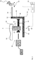
FIG. 2 is a plan view of an overspeed assembly of an elevator system according to an embodiment; -
FIG. 3 is a plan view of an overspeed assembly of an elevator system in a first position according to an embodiment; -
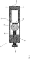
FIG. 4 is an end view of the bell crank lever of the overspeed assembly ofFIG. 3 according to an embodiment; -
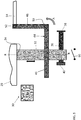
FIG. 5 is a plan view of an overspeed assembly of an elevator system in a second position according to an embodiment; and -
FIG. 6 is an end view of the bell crank lever of the overspeed assembly ofFIG. 5 according to an embodiment. - A detailed description of one or more embodiments of the disclosed apparatus and method are presented herein by way of exemplification and not limitation with reference to the Figures.
- Referring now to
FIG. 1 , an elevator system including anelevator car 12, guide rails 14, and agovernor assembly 16 is illustrated. Thegovernor assembly 16 includes agovernor sheave 18, acentrifugal mechanism 28, a rope loop 22, and a rope tensioning assembly 24 including atensioning sheave 25. Theelevator car 12 travels on or is slidably connected to the guide rails 14 and travels within a hoistway (not shown). The governor sheave 18 and thecentrifugal mechanism 28 are mounted, in the illustrated, non-limiting embodiment, at an upper end of the hoistway. The rope loop 22 is wrapped partially around thegovernor sheave 18 and partially around the tensioning sheave 25 (located in this embodiment at a bottom end of the hoistway). The rope loop 22 is also connected to theelevator car 12, thereby ensuring that the angular velocity of thegovernor sheave 18 is related to the speed of theelevator car 12. - In the elevator system shown in
FIG. 1 , thegovernor assembly 16 acts to prevent theelevator car 12 from exceeding a set speed as it travels inside the hoistway. Although thegovernor assembly 16 shown inFIG. 1 is mounted at an upper end of the hoistway, the location and arrangement of thegovernor assembly 16 may vary across different embodiments of the present disclosure. For example, thegovernor assembly 16 may be mounted at any point along the rope loop 22 in the hoistway, including at the bottom, i.e. the pit, of the hoistway. In another embodiment, thegovernor assembly 16 may alternatively, be mounted to and move with theelevator car 12. Such an alternative embodiment involves a static rope anchored at the top and tensioned by a weight or an elastic member at the bottom of the hoistway and wrapped partially around thetripping sheave 18 and an adjacent idler sheave. - With reference now to
FIGS. 2-6 , in an embodiment, thecentrifugal mechanism 28 is operably coupled to thegovernor sheave 18. For example, as is known in the art, thecentrifugal mechanism 28 may include a connector associated with one or morecentrifugal elements 29 configured to rotate with thegovernor sheave 18 as theelevator car 12 moves. As theelevator car 12 moves, the governor sheave 18 and thecentrifugal mechanism 28 rotate. The resulting centrifugal force acting on the one or morecentrifugal elements 29 due to this movement of thecar 12 causes the connector and thecentrifugal elements 29 to move relative to the axis of rotation. Thecentrifugal mechanism 28 described herein is intended as an example only, and it should be understood that any suitablecentrifugal mechanism 28 is within the scope of the disclosure. - An example of an
overspeed assembly 30 compatible for use with thegovernor sheave 18 of thegovernor assembly 16 is illustrated. As shown, theoverspeed assembly 30 includes arod 32 coupled at afirst end 34 to a movable portion of thegovernor sheave 18, and more specifically to a portion of thecentrifugal mechanism 28, such as acentrifugal element 29 for example. In an embodiment, the outward radial movement of thecentrifugal elements 29 results in movement of therod 32. In the illustrated, non-limiting embodiment, therod 32 is oriented generally parallel to an axis of rotation R of thecentrifugal mechanism 28 andgovernor sheave 18 and is configured to translate along the axis R. However, embodiments where therod 32 is oriented at another angle relative to the axis of rotation R are also contemplated herein. Therod 32 may be formed from any suitable material, including but not limited to plastic for example. - A
pin 36 extends through an opening formed in the body of therod 32, in an orientation generally perpendicular to the axis of rotation R of thecentrifugal mechanism 28. Thepin 36 may be formed from any suitable material, such as plastic or metal for example. Ahead 38 arranged at a first end of thepin 36 has a diameter greater than the diameter of the opening formed in therod 32. As a result, engagement between thehead 38 and therod 32 limits movement of thepin 36 relative torod 32 in a first direction. Aprimary magnet 40, such as a permanent magnet for example, is mounted to a second, opposite end of thepin 36. Similarly, themagnet 40 has a diameter greater than the diameter of the opening formed in therod 32. As a result, engagement between themagnet 40 and therod 32 limits movement of thepin 36 relative torod 32 in a second, opposite direction. - Mounted within the hoistway generally adjacent the second end of the
pin 36 is asecondary magnet 42. In an embodiment, themagnet 42 is an electromagnet. However any suitable type ofmagnet 42 is within the scope of the disclosure. Themagnet 42 is selectively operable to generate a magnetic force configured to either attract or repel themagnet 40 coupled to the second end of thepin 36. This attraction or repulsion is used to move thepin 36 between a first position (FIGS. 3 and4 ) and a second position (FIGS. 5 and6 ) relative to therod 32. The desired position of thepin 36 may be selected, for example, based on a direction of travel of theelevator car 12. In the illustrated, non-limiting embodiment, thepin 36 is in the first position when theelevator car 12 is travelling in a first, downward direction and is in the second position when theelevator car 12 is travelling in a second, upward direction within the hoistway. - The
governor assembly 16 includes a bell cranklever 44 mounted within the hoistway at a position offset from thecentrifugal mechanism 28 by a distance. As a result, therod 32 is positioned generally between thecentrifugal mechanism 28 and the bell cranklever 44. As shown, the bell cranklevel 44 includes an integrally formedfirst portion 46 andsecond portion 48. In the illustrated, non-limiting embodiment, thefirst portion 46 is oriented substantially parallel to thepin 36 and thesecond portion 48 is oriented substantially parallel to therod 32 such that theinterface 50 between thefirst portion 46 and thesecond portion 48 defines a bend in the bell cranklever 44. Adistal end 52 of thesecond portion 48 of the bell cranklever 44 is pivotally coupled to aconnector 54 associated with a release lever (not shown) and a firstoverspeed actuation switch 56. In addition, the bell cranklever 44 is configured to pivot about an axis X (best shown inFIG. 4 ) defined at theinterface 50 between the first andsecond portions rod 32 andpin 36. - In an embodiment, best shown in
FIGS. 4 and6 , a cutout or throughhole 58 is formed in thefirst portion 46 of the bell cranklever 44. The cut out 58 is generally equal or larger in length and width than thepin 36 including both thehead 38 and themagnet 40. In the illustrated, non-limiting embodiment, the throughhole 58 is positioned adjacent theinterface 50 between the first andsecond portions hole 58 is generally aligned with thepin 36 when thepin 36 is in the second position. - With specific reference now to
FIGS. 3 and4 , upon determining that thecar 12 is configured to move in a first direction, such as a downward direction for example, a controller 60 (FIG. 2 ) operably coupled to thesecondary magnet 42 communicates a signal to themagnet 42, or a power source associated therewith. As a result, thesecondary magnet 42 is energized and the resulting magnetic field has an opposite polarization as the magnetic field of themagnet 40 mounted to thepin 36. The interaction between the magnetic fields of the primary andsecondary magnets pin 36 to translate within the opening, relative to therod 32, to a first position. In the first position, thehead 38 of thepin 36 may be arranged generally adjacent or in direct contact with a surface of therod 32. Further, in the illustrated, non-limiting embodiment, the length of thepin 36 is selected such that the second end ormagnet 40 of thepin 36 extends axially beyond thefree end 62 of thefirst portion 46 of the bell cranklever 44 when in the first position. Accordingly, in the first position, thepin 36 is not aligned with the throughhole 58 formed in thefirst portion 46 of the bell cranklever 44. - As the speed of the
elevator car 12 travelling in the first direction increases, the distance that therod 32 extends from thegovernor sheave 18 also increases. Accordingly, the distance between therod 32 and the bell cranklever 44 similarly decreases. If the speed of theelevator car 12 travelling in the first direction exceeds a first overspeed threshold, the movement of therod 32 causes thepin 36 to apply a force to thefirst portion 46 of the bell cranklever 44. This force rotates the bell cranklever 44 about its axis X, as indicated by arrow A, such that a corresponding force is applied to theconnector 54 to operate theoverspeed switch 56. Operation of theswitch 56 may be configured to interrupt the power being supplied to a motor 57 (seeFIG. 2 ) driving movement of theelevator car 12 within the hoistway and/or apply abrake 59 to themotor 57 to slow movement of theelevator car 12. - If the speed of the
elevator car 12 travelling in the first direction exceeds a second overspeed threshold, the further movement of therod 32 relative to thecentrifugal mechanism 28, and the resulting engagement between thepin 36 and the bell cranklever 44, causes the bell cranklever 44 to rotate further about its axis X, in the direction indicated by arrow A. This further rotation causes theconnector 54 to operate a jaw mechanism, illustrated at 64 inFIG. 2 , and initiate engagement of the elevator safeties. Through this activation, one or more elevator safeties are moved into frictional engagement with the guide rails 14 supporting theelevator car 12, as is known in the art. - Because the distance that the
rod 32 extends from thegovernor sheave 18 and/orcentrifugal mechanism 28 also increases as the speed of theelevator car 12 increases and engagement between thepin 36 in the first position and the bell cranklever 44 is used to indicate an overspeed condition, the distance between thecentrifugal mechanism 28 and thefirst portion 46 of the bell cranklever 44 is selected based on the threshold of the first overspeed condition. Accordingly, the position of the bell cranklever 44 may be located either closer to or further from thecentrifugal mechanism 28 to reduce or increase the threshold of the first overspeed condition, respectively. Alternatively, or in addition, because the radial movement of thecentrifugal elements 29 is configured to control the translation of therod 32 relative to the bell cranklever 44, this movement of thecentrifugal elements 29 may be controlled to achieve a desired threshold of the first overspeed condition. - With reference to
FIGS. 5 and6 , upon determining that thecar 12 is configured to move in a second direction, such as an upward direction for example, thecontroller 60 generates a signal to energize thesecondary magnet 42 and create a magnetic field with a similar polarization to themagnet 40 affixed to thepin 36. The interaction between the magnetic fields of themagnets pin 36 to translate within the opening, relative to therod 32, to the second position. In the second position, themagnet 40 of thepin 36 is arranged generally adjacent or in direct contact with a surface of therod 32. Further, in the second position, thepin 36 is generally aligned with the throughhole 58 formed in thefirst portion 44 of the bell cranklever 46. - As the speed of the
elevator car 12 moving in the second direction increases, the distance that therod 32 extends from thecentrifugal mechanism 28 also increases. Therod 32 is configured to move in the same direction relative to thecentrifugal mechanism 28 regardless of whether theelevator car 12 is moving in the first direction or the second direction. Because the threshold associated with an overspeed condition during movement of theelevator car 12 in the second direction is greater than the threshold associated with an overspeed condition during movement of theelevator car 12 in the first direction, therod 32 andpin 36 will be received within and ultimately extend through the throughhole 58 formed in the bell cranklever 44. - As the speed of the
elevator car 12 travelling in the second direction increases, and ultimately exceeds a threshold associated with an overspeed condition, the distal end of therod 32 will contact anoverspeed switch 66. Operation of theoverspeed switch 66 will activate or drop the machine brake and interrupt power to the machine motor, as is known in the art. - The position of the
overspeed switch 66 relative to thecentrifugal mechanism 28 and the movement of therod 32 is selected based on the threshold of the overspeed condition when the elevator car is travelling in the second direction. Accordingly, the position of theoverspeed switch 66 may be located either closer to or further from thecentrifugal mechanism 28 to reduce or increase the threshold of the overspeed condition, based on earlier or later actuation by therod 32. - The
overspeed assembly 30 illustrated and described herein provides a first overspeed threshold for travel of anelevator car 12 in a first direction and a second, distinct overspeed threshold for travel of anelevator car 12 in a second, opposite direction. In an embodiment, the first overspeed threshold for travel in the down direction is between 8 and 10 m/s and the second overspeed threshold for travel in the up direction is between 12 and 18 m/s. However, any speeds are within the scope of the disclosure. Further,governor assemblies 16 in an existing elevator system may be adapted to include theoverspeed assembly 30 with minimal changes to the existing components. - The term "about" is intended to include the degree of error associated with measurement of the particular quantity based upon the equipment available at the time of filing the application.
- The terminology used herein is for the purpose of describing particular embodiments only and is not intended to be limiting of the present disclosure. As used herein, the singular forms "a", "an" and "the" are intended to include the plural forms as well, unless the context clearly indicates otherwise. It will be further understood that the terms "comprises" and/or "comprising," when used in this specification, specify the presence of stated features, integers, steps, operations, elements, and/or components, but do not preclude the presence or addition of one or more other features, integers, steps, operations, element components, and/or groups thereof.
- While the present disclosure has been described with reference to an exemplary embodiment or embodiments, it will be understood by those skilled in the art that various changes may be made and equivalents may be substituted for elements thereof without departing from the scope of the present disclosure. In addition, many modifications may be made to adapt a particular situation or material to the teachings of the present disclosure without departing from the essential scope thereof. Therefore, it is intended that the present disclosure not be limited to the particular embodiment disclosed as the best mode contemplated for carrying out this present disclosure, but that the present disclosure will include all embodiments falling within the scope of the claims.
Claims (15)
- An overspeed assembly for use with a governor assembly for limiting of an elevator system, the overspeed assembly comprising:a rod movable relative to the governor assembly in response to a speed of an elevator car;a pin coupled to the rod, the pin being movable between a first position and a second position based on a direction of travel of the elevator car, wherein the pin is configured to engage a first component to indicate a first overspeed condition when the elevator car is travelling in a first direction and the pin is configured to engage a second component to indicate a second overspeed condition when the elevator car is travelling in a second, opposite direction.
- The overspeed assembly of claim 1, wherein the first overspeed condition and the second overspeed condition are distinct.
- The overspeed assembly of claim 1 or 2, wherein the pin is oriented substantially perpendicular to the rod.
- The overspeed assembly of claim 1, 2 or 3, wherein when the elevator car is travelling in the first direction, the pin is in the first position and when the elevator car is travelling in the second direction, the pin is in the second position.
- The overspeed assembly of any preceding claim, wherein the pin further comprises a first magnet, and the overspeed assembly includes a second magnet, the second magnet being selectively operable to attract and repel the first magnet to move the pin between the first position and the second position.
- The overspeed assembly of claim 5, further comprising a controller operably coupled to the second magnet, wherein the controller energizes the second magnet to attract and repel the first magnet in response to a direction of travel of the elevator car.
- The overspeed assembly of any preceding claim, wherein the governor assembly further comprises:a governor sheave; anda centrifugal mechanism movably mounted to the governor sheave, the rod being connected to the centrifugal mechanism.
- The overspeed assembly of claim 7, wherein the governor assembly further comprises a bell crank lever offset from governor sheave by a distance; and optionally
wherein the bell crank lever includes a through hole, the pin being receivable within the through hole when the pin is in the second position. - The overspeed assembly of claim 8, further comprising a switch positioned adjacent the bell crank lever, wherein when the elevator car is travelling in the second direction in the second overspeed condition, the pin operates the switch.
- The overspeed assembly of claim 8 or 9, wherein the bell crank lever is the first component; and optionally
further comprising an elevator safety operably coupled to the bell crank lever wherein when the elevator car is travelling in the first direction in a third overspeed condition, the pin engages the bell crank lever to engage the elevator safety. - The overspeed assembly of claim 10, further comprising a switch operably coupled to the bell crank lever, wherein when the elevator car is travelling in the first direction in the first overspeed condition, the pin engages the bell crank lever to operate the switch; and optionally
further comprising a motor for driving movement of the elevator car, wherein the switch is configured to at least one of interrupt a supply of power to the motor and apply a brake to the motor. - A method of controlling a speed an elevator car within a hoistway comprising:moving an elevator car in a first direction within the hoistway;operating a switch via engagement between an overspeed assembly and a first component coupled to the switch in response to a first overspeed condition;moving the elevator car in a second direction within the hoistway; andextending the overspeed assembly through an opening formed in the first component; andoperating another switch via the overspeed assembly in response to a second overspeed condition.
- The method of claim 12, wherein operating the switch via engagement between an overspeed assembly and a first component in response to a first overspeed condition further comprises at least one of interrupting a supply of power to a motor operable to move the elevator car and applying a brake to the motor.
- The method of claim 12 or 13, further comprising initiating engagement of at least one elevator safety via engagement between the overspeed assembly and the first component in response to a third overspeed condition; and optionally
wherein the third overspeed condition is a greater speed than the first overspeed condition. - The method of claim 12, 13 or 14, wherein operating another switch via the overspeed assembly in response to a second overspeed condition further comprises at least one of interrupting a supply of power to a motor operable to move the elevator car and applying a brake to the motor.
Applications Claiming Priority (1)
| Application Number | Priority Date | Filing Date | Title |
|---|---|---|---|
| US16/040,361 US10968077B2 (en) | 2018-07-19 | 2018-07-19 | Enhanced governor system for elevator |
Publications (2)
| Publication Number | Publication Date |
|---|---|
| EP3597583A1 true EP3597583A1 (en) | 2020-01-22 |
| EP3597583B1 EP3597583B1 (en) | 2024-12-25 |
Family
ID=67438261
Family Applications (1)
| Application Number | Title | Priority Date | Filing Date |
|---|---|---|---|
| EP19187443.7A Active EP3597583B1 (en) | 2018-07-19 | 2019-07-19 | Enhanced speed limit governor system for elevator |
Country Status (3)
| Country | Link |
|---|---|
| US (1) | US10968077B2 (en) |
| EP (1) | EP3597583B1 (en) |
| CN (1) | CN110733951B (en) |
Cited By (1)
| Publication number | Priority date | Publication date | Assignee | Title |
|---|---|---|---|---|
| CN115893145A (en) * | 2021-08-23 | 2023-04-04 | 奥的斯电梯公司 | safety braking system |
Families Citing this family (3)
| Publication number | Priority date | Publication date | Assignee | Title |
|---|---|---|---|---|
| US11034546B2 (en) * | 2018-06-28 | 2021-06-15 | Otis Elevator Company | Elevator governor |
| US10968077B2 (en) * | 2018-07-19 | 2021-04-06 | Otis Elevator Company | Enhanced governor system for elevator |
| CN117228477B (en) * | 2022-06-06 | 2025-09-09 | 杭州沪宁电梯部件股份有限公司 | Novel electronic speed limiter and elevator |
Citations (3)
| Publication number | Priority date | Publication date | Assignee | Title |
|---|---|---|---|---|
| WO2012086026A1 (en) * | 2010-12-22 | 2012-06-28 | 三菱電機株式会社 | Speed governing device of elevator |
| WO2013179336A1 (en) * | 2012-05-30 | 2013-12-05 | 株式会社 日立製作所 | Elevator device |
| CN106276465A (en) * | 2015-06-29 | 2017-01-04 | 株式会社日立制作所 | Lift appliance and limiter of speed thereof |
Family Cites Families (30)
| Publication number | Priority date | Publication date | Assignee | Title |
|---|---|---|---|---|
| US3327811A (en) * | 1966-10-28 | 1967-06-27 | Otis Elevator Co | Governor |
| US4662481A (en) | 1986-03-14 | 1987-05-05 | Westinghouse Electric Corp. | Elevator system |
| US5217091A (en) * | 1992-10-20 | 1993-06-08 | Otis Elevator Company | Mechanical overspeed safety device |
| US5299661A (en) * | 1992-11-03 | 1994-04-05 | Otis Elevator Company | Mechanical overspeed safety device |
| FI95021C (en) * | 1993-06-08 | 1995-12-11 | Kone Oy | Method and apparatus for triggering an elevator gripping device |
| JP2790615B2 (en) * | 1994-10-20 | 1998-08-27 | 三菱電機株式会社 | Elevator governor |
| DE19906073C2 (en) * | 1999-02-12 | 2003-03-27 | Inventio Ag | Device for preventing uncontrolled accelerations of a car in an elevator installation |
| JP4306014B2 (en) * | 1999-05-17 | 2009-07-29 | 三菱電機株式会社 | Governor |
| US6691834B2 (en) * | 2001-09-06 | 2004-02-17 | Otis Elevator Company | Elevator governor |
| EP1497214A4 (en) | 2002-04-24 | 2010-12-29 | Mitsubishi Electric Corp | OVERSIZE CONTROLLER APPARATUS FOR ELEVATOR SYSTEM |
| JP4326255B2 (en) | 2003-04-14 | 2009-09-02 | 東芝エレベータ株式会社 | Elevator governor |
| JP4423261B2 (en) * | 2003-11-18 | 2010-03-03 | オーチス エレベータ カンパニー | Elevator governor device |
| BRPI0622155A2 (en) * | 2006-12-20 | 2011-12-27 | Otis Elevator Co | set to control motion of an elevator car |
| EP2177466A4 (en) * | 2007-08-09 | 2014-01-15 | Mitsubishi Electric Corp | ELEVATOR SPEED REGULATOR |
| JP5360201B2 (en) * | 2009-04-09 | 2013-12-04 | 三菱電機株式会社 | Elevator governor |
| JP5577736B2 (en) | 2010-02-18 | 2014-08-27 | 三菱電機株式会社 | Elevator governor |
| EP2602222A1 (en) | 2010-08-06 | 2013-06-12 | Mitsubishi Electric Corporation | Elevator speed governor |
| CN103339053B (en) * | 2011-02-07 | 2016-02-10 | 奥的斯电梯公司 | Independent pulley has the elevator governor of two releasing mechanisms |
| EP2855325B1 (en) * | 2012-05-31 | 2021-08-25 | Otis Elevator Company | Car mounted overspeed governor actuation device |
| JP6239736B2 (en) | 2014-04-16 | 2017-11-29 | 株式会社日立製作所 | Elevator equipment |
| CN106715314A (en) * | 2014-06-18 | 2017-05-24 | 奥的斯电梯公司 | System and method of operating a governor with independent threshold speeds |
| WO2015198384A1 (en) | 2014-06-24 | 2015-12-30 | 株式会社日立製作所 | Elevator governor and elevator device using same |
| JP5870165B2 (en) | 2014-07-08 | 2016-02-24 | 東芝エレベータ株式会社 | Elevator governor |
| WO2016079823A1 (en) * | 2014-11-19 | 2016-05-26 | 三菱電機株式会社 | Elevator apparatus |
| ES2698365T3 (en) * | 2015-09-12 | 2019-02-04 | Otis Elevator Co | Elevator speeding regulator |
| CN107021395B (en) * | 2016-01-04 | 2020-11-10 | 奥的斯电梯公司 | Elevator overspeed governor with automatic reset |
| CN107673159B (en) * | 2016-08-01 | 2020-09-08 | 奥的斯电梯公司 | Speed limiter of elevator |
| CN108002168B (en) * | 2016-10-27 | 2021-04-02 | 奥的斯电梯公司 | Remote triggering device, speed limiter assembly and elevator |
| US10968077B2 (en) * | 2018-07-19 | 2021-04-06 | Otis Elevator Company | Enhanced governor system for elevator |
| US10822200B2 (en) * | 2018-10-12 | 2020-11-03 | Otis Elevator Company | Elevator safety actuator systems |
-
2018
- 2018-07-19 US US16/040,361 patent/US10968077B2/en active Active
-
2019
- 2019-07-18 CN CN201910650001.3A patent/CN110733951B/en active Active
- 2019-07-19 EP EP19187443.7A patent/EP3597583B1/en active Active
Patent Citations (3)
| Publication number | Priority date | Publication date | Assignee | Title |
|---|---|---|---|---|
| WO2012086026A1 (en) * | 2010-12-22 | 2012-06-28 | 三菱電機株式会社 | Speed governing device of elevator |
| WO2013179336A1 (en) * | 2012-05-30 | 2013-12-05 | 株式会社 日立製作所 | Elevator device |
| CN106276465A (en) * | 2015-06-29 | 2017-01-04 | 株式会社日立制作所 | Lift appliance and limiter of speed thereof |
Cited By (1)
| Publication number | Priority date | Publication date | Assignee | Title |
|---|---|---|---|---|
| CN115893145A (en) * | 2021-08-23 | 2023-04-04 | 奥的斯电梯公司 | safety braking system |
Also Published As
| Publication number | Publication date |
|---|---|
| CN110733951B (en) | 2022-03-11 |
| CN110733951A (en) | 2020-01-31 |
| EP3597583B1 (en) | 2024-12-25 |
| US10968077B2 (en) | 2021-04-06 |
| US20200024106A1 (en) | 2020-01-23 |
Similar Documents
| Publication | Publication Date | Title |
|---|---|---|
| EP3597583B1 (en) | Enhanced speed limit governor system for elevator | |
| EP3112306B1 (en) | Electromagnetic safety trigger | |
| AU2022202242B2 (en) | Tuning of a Kinematic Relationship Between Members | |
| US11066274B2 (en) | Electromagnetic safety trigger | |
| KR100617420B1 (en) | Electronic elevator safety system | |
| CN102892699B (en) | Integrated elevator safety system | |
| US10246295B2 (en) | Protective device for speed sensing device | |
| US11649139B2 (en) | Electronic safety actuator assembly for elevator system | |
| US5217091A (en) | Mechanical overspeed safety device | |
| US10329120B2 (en) | Elevator overspeed governor | |
| EP3377433B1 (en) | Housing assembly for a safety actuation device | |
| US12330917B2 (en) | Safety brake system | |
| EP3536649A2 (en) | Magnetic speed detection device | |
| EP3587328B1 (en) | Electromagnetic safety trigger | |
| US7137484B2 (en) | Safety system for restraining movement of elevator car when car doors are open | |
| JP2008094544A (en) | Limit switch operation mechanism and speed governor having this mechanism | |
| KR102022235B1 (en) | Elevator braking system | |
| US11939189B2 (en) | Frictionless electronic safety actuator | |
| CN102574664A (en) | Movement governor and elevator | |
| WO2012011903A1 (en) | Magnetic governor device for use in an elevator system | |
| EP4389668A1 (en) | Governor assembly for an elevator |
Legal Events
| Date | Code | Title | Description |
|---|---|---|---|
| PUAI | Public reference made under article 153(3) epc to a published international application that has entered the european phase |
Free format text: ORIGINAL CODE: 0009012 |
|
| STAA | Information on the status of an ep patent application or granted ep patent |
Free format text: STATUS: THE APPLICATION HAS BEEN PUBLISHED |
|
| AK | Designated contracting states |
Kind code of ref document: A1 Designated state(s): AL AT BE BG CH CY CZ DE DK EE ES FI FR GB GR HR HU IE IS IT LI LT LU LV MC MK MT NL NO PL PT RO RS SE SI SK SM TR |
|
| AX | Request for extension of the european patent |
Extension state: BA ME |
|
| STAA | Information on the status of an ep patent application or granted ep patent |
Free format text: STATUS: REQUEST FOR EXAMINATION WAS MADE |
|
| 17P | Request for examination filed |
Effective date: 20200721 |
|
| RBV | Designated contracting states (corrected) |
Designated state(s): AL AT BE BG CH CY CZ DE DK EE ES FI FR GB GR HR HU IE IS IT LI LT LU LV MC MK MT NL NO PL PT RO RS SE SI SK SM TR |
|
| STAA | Information on the status of an ep patent application or granted ep patent |
Free format text: STATUS: EXAMINATION IS IN PROGRESS |
|
| 17Q | First examination report despatched |
Effective date: 20210413 |
|
| GRAP | Despatch of communication of intention to grant a patent |
Free format text: ORIGINAL CODE: EPIDOSNIGR1 |
|
| STAA | Information on the status of an ep patent application or granted ep patent |
Free format text: STATUS: GRANT OF PATENT IS INTENDED |
|
| INTG | Intention to grant announced |
Effective date: 20240307 |
|
| GRAJ | Information related to disapproval of communication of intention to grant by the applicant or resumption of examination proceedings by the epo deleted |
Free format text: ORIGINAL CODE: EPIDOSDIGR1 |
|
| STAA | Information on the status of an ep patent application or granted ep patent |
Free format text: STATUS: EXAMINATION IS IN PROGRESS |
|
| GRAP | Despatch of communication of intention to grant a patent |
Free format text: ORIGINAL CODE: EPIDOSNIGR1 |
|
| STAA | Information on the status of an ep patent application or granted ep patent |
Free format text: STATUS: GRANT OF PATENT IS INTENDED |
|
| INTC | Intention to grant announced (deleted) | ||
| INTG | Intention to grant announced |
Effective date: 20240723 |
|
| GRAS | Grant fee paid |
Free format text: ORIGINAL CODE: EPIDOSNIGR3 |
|
| GRAA | (expected) grant |
Free format text: ORIGINAL CODE: 0009210 |
|
| STAA | Information on the status of an ep patent application or granted ep patent |
Free format text: STATUS: THE PATENT HAS BEEN GRANTED |
|
| AK | Designated contracting states |
Kind code of ref document: B1 Designated state(s): AL AT BE BG CH CY CZ DE DK EE ES FI FR GB GR HR HU IE IS IT LI LT LU LV MC MK MT NL NO PL PT RO RS SE SI SK SM TR |
|
| REG | Reference to a national code |
Ref country code: GB Ref legal event code: FG4D |
|
| REG | Reference to a national code |
Ref country code: CH Ref legal event code: EP |
|
| REG | Reference to a national code |
Ref country code: DE Ref legal event code: R096 Ref document number: 602019063886 Country of ref document: DE |
|
| REG | Reference to a national code |
Ref country code: IE Ref legal event code: FG4D |
|
| REG | Reference to a national code |
Ref country code: LT Ref legal event code: MG9D |
|
| PG25 | Lapsed in a contracting state [announced via postgrant information from national office to epo] |
Ref country code: HR Free format text: LAPSE BECAUSE OF FAILURE TO SUBMIT A TRANSLATION OF THE DESCRIPTION OR TO PAY THE FEE WITHIN THE PRESCRIBED TIME-LIMIT Effective date: 20241225 |
|
| PG25 | Lapsed in a contracting state [announced via postgrant information from national office to epo] |
Ref country code: FI Free format text: LAPSE BECAUSE OF FAILURE TO SUBMIT A TRANSLATION OF THE DESCRIPTION OR TO PAY THE FEE WITHIN THE PRESCRIBED TIME-LIMIT Effective date: 20241225 |
|
| PG25 | Lapsed in a contracting state [announced via postgrant information from national office to epo] |
Ref country code: BG Free format text: LAPSE BECAUSE OF FAILURE TO SUBMIT A TRANSLATION OF THE DESCRIPTION OR TO PAY THE FEE WITHIN THE PRESCRIBED TIME-LIMIT Effective date: 20241225 |
|
| PG25 | Lapsed in a contracting state [announced via postgrant information from national office to epo] |
Ref country code: NO Free format text: LAPSE BECAUSE OF FAILURE TO SUBMIT A TRANSLATION OF THE DESCRIPTION OR TO PAY THE FEE WITHIN THE PRESCRIBED TIME-LIMIT Effective date: 20250325 |
|
| PG25 | Lapsed in a contracting state [announced via postgrant information from national office to epo] |
Ref country code: LV Free format text: LAPSE BECAUSE OF FAILURE TO SUBMIT A TRANSLATION OF THE DESCRIPTION OR TO PAY THE FEE WITHIN THE PRESCRIBED TIME-LIMIT Effective date: 20241225 Ref country code: GR Free format text: LAPSE BECAUSE OF FAILURE TO SUBMIT A TRANSLATION OF THE DESCRIPTION OR TO PAY THE FEE WITHIN THE PRESCRIBED TIME-LIMIT Effective date: 20250326 |
|
| PG25 | Lapsed in a contracting state [announced via postgrant information from national office to epo] |
Ref country code: RS Free format text: LAPSE BECAUSE OF FAILURE TO SUBMIT A TRANSLATION OF THE DESCRIPTION OR TO PAY THE FEE WITHIN THE PRESCRIBED TIME-LIMIT Effective date: 20250325 |
|
| REG | Reference to a national code |
Ref country code: NL Ref legal event code: MP Effective date: 20241225 |
|
| PG25 | Lapsed in a contracting state [announced via postgrant information from national office to epo] |
Ref country code: NL Free format text: LAPSE BECAUSE OF FAILURE TO SUBMIT A TRANSLATION OF THE DESCRIPTION OR TO PAY THE FEE WITHIN THE PRESCRIBED TIME-LIMIT Effective date: 20241225 |
|
| REG | Reference to a national code |
Ref country code: AT Ref legal event code: MK05 Ref document number: 1754026 Country of ref document: AT Kind code of ref document: T Effective date: 20241225 |
|
| PG25 | Lapsed in a contracting state [announced via postgrant information from national office to epo] |
Ref country code: SM Free format text: LAPSE BECAUSE OF FAILURE TO SUBMIT A TRANSLATION OF THE DESCRIPTION OR TO PAY THE FEE WITHIN THE PRESCRIBED TIME-LIMIT Effective date: 20241225 |
|
| PG25 | Lapsed in a contracting state [announced via postgrant information from national office to epo] |
Ref country code: PL Free format text: LAPSE BECAUSE OF FAILURE TO SUBMIT A TRANSLATION OF THE DESCRIPTION OR TO PAY THE FEE WITHIN THE PRESCRIBED TIME-LIMIT Effective date: 20241225 |
|
| PG25 | Lapsed in a contracting state [announced via postgrant information from national office to epo] |
Ref country code: ES Free format text: LAPSE BECAUSE OF FAILURE TO SUBMIT A TRANSLATION OF THE DESCRIPTION OR TO PAY THE FEE WITHIN THE PRESCRIBED TIME-LIMIT Effective date: 20241225 |
|
| PG25 | Lapsed in a contracting state [announced via postgrant information from national office to epo] |
Ref country code: IS Free format text: LAPSE BECAUSE OF FAILURE TO SUBMIT A TRANSLATION OF THE DESCRIPTION OR TO PAY THE FEE WITHIN THE PRESCRIBED TIME-LIMIT Effective date: 20250425 |
|
| PG25 | Lapsed in a contracting state [announced via postgrant information from national office to epo] |
Ref country code: PT Free format text: LAPSE BECAUSE OF FAILURE TO SUBMIT A TRANSLATION OF THE DESCRIPTION OR TO PAY THE FEE WITHIN THE PRESCRIBED TIME-LIMIT Effective date: 20250428 |
|
| PG25 | Lapsed in a contracting state [announced via postgrant information from national office to epo] |
Ref country code: EE Free format text: LAPSE BECAUSE OF FAILURE TO SUBMIT A TRANSLATION OF THE DESCRIPTION OR TO PAY THE FEE WITHIN THE PRESCRIBED TIME-LIMIT Effective date: 20241225 |
|
| PGFP | Annual fee paid to national office [announced via postgrant information from national office to epo] |
Ref country code: FR Payment date: 20250620 Year of fee payment: 7 |
|
| PG25 | Lapsed in a contracting state [announced via postgrant information from national office to epo] |
Ref country code: RO Free format text: LAPSE BECAUSE OF FAILURE TO SUBMIT A TRANSLATION OF THE DESCRIPTION OR TO PAY THE FEE WITHIN THE PRESCRIBED TIME-LIMIT Effective date: 20241225 Ref country code: AT Free format text: LAPSE BECAUSE OF FAILURE TO SUBMIT A TRANSLATION OF THE DESCRIPTION OR TO PAY THE FEE WITHIN THE PRESCRIBED TIME-LIMIT Effective date: 20241225 |
|
| PG25 | Lapsed in a contracting state [announced via postgrant information from national office to epo] |
Ref country code: SK Free format text: LAPSE BECAUSE OF FAILURE TO SUBMIT A TRANSLATION OF THE DESCRIPTION OR TO PAY THE FEE WITHIN THE PRESCRIBED TIME-LIMIT Effective date: 20241225 |
|
| PG25 | Lapsed in a contracting state [announced via postgrant information from national office to epo] |
Ref country code: CZ Free format text: LAPSE BECAUSE OF FAILURE TO SUBMIT A TRANSLATION OF THE DESCRIPTION OR TO PAY THE FEE WITHIN THE PRESCRIBED TIME-LIMIT Effective date: 20241225 |
|
| PG25 | Lapsed in a contracting state [announced via postgrant information from national office to epo] |
Ref country code: IT Free format text: LAPSE BECAUSE OF FAILURE TO SUBMIT A TRANSLATION OF THE DESCRIPTION OR TO PAY THE FEE WITHIN THE PRESCRIBED TIME-LIMIT Effective date: 20241225 |
|
| PG25 | Lapsed in a contracting state [announced via postgrant information from national office to epo] |
Ref country code: SE Free format text: LAPSE BECAUSE OF FAILURE TO SUBMIT A TRANSLATION OF THE DESCRIPTION OR TO PAY THE FEE WITHIN THE PRESCRIBED TIME-LIMIT Effective date: 20241225 |
|
| REG | Reference to a national code |
Ref country code: DE Ref legal event code: R097 Ref document number: 602019063886 Country of ref document: DE |
|
| PG25 | Lapsed in a contracting state [announced via postgrant information from national office to epo] |
Ref country code: DK Free format text: LAPSE BECAUSE OF FAILURE TO SUBMIT A TRANSLATION OF THE DESCRIPTION OR TO PAY THE FEE WITHIN THE PRESCRIBED TIME-LIMIT Effective date: 20241225 |
|
| PGFP | Annual fee paid to national office [announced via postgrant information from national office to epo] |
Ref country code: DE Payment date: 20250620 Year of fee payment: 7 |
|
| PLBE | No opposition filed within time limit |
Free format text: ORIGINAL CODE: 0009261 |
|
| STAA | Information on the status of an ep patent application or granted ep patent |
Free format text: STATUS: NO OPPOSITION FILED WITHIN TIME LIMIT |
|
| REG | Reference to a national code |
Ref country code: CH Ref legal event code: L10 Free format text: ST27 STATUS EVENT CODE: U-0-0-L10-L00 (AS PROVIDED BY THE NATIONAL OFFICE) Effective date: 20251105 |
|
| 26N | No opposition filed |
Effective date: 20250926 |
|
| REG | Reference to a national code |
Ref country code: CH Ref legal event code: H13 Free format text: ST27 STATUS EVENT CODE: U-0-0-H10-H13 (AS PROVIDED BY THE NATIONAL OFFICE) Effective date: 20260224 |
|
| PG25 | Lapsed in a contracting state [announced via postgrant information from national office to epo] |
Ref country code: LU Free format text: LAPSE BECAUSE OF NON-PAYMENT OF DUE FEES Effective date: 20250719 |
|
| GBPC | Gb: european patent ceased through non-payment of renewal fee |
Effective date: 20250719 |
|
| REG | Reference to a national code |
Ref country code: BE Ref legal event code: MM Effective date: 20250731 |
|
| PG25 | Lapsed in a contracting state [announced via postgrant information from national office to epo] |
Ref country code: GB Free format text: LAPSE BECAUSE OF NON-PAYMENT OF DUE FEES Effective date: 20250719 |
|
| PG25 | Lapsed in a contracting state [announced via postgrant information from national office to epo] |
Ref country code: BE Free format text: LAPSE BECAUSE OF NON-PAYMENT OF DUE FEES Effective date: 20250731 |
|
| PG25 | Lapsed in a contracting state [announced via postgrant information from national office to epo] |
Ref country code: CH Free format text: LAPSE BECAUSE OF NON-PAYMENT OF DUE FEES Effective date: 20250731 |