EP3597493A1 - A pedal group - Google Patents
A pedal group Download PDFInfo
- Publication number
- EP3597493A1 EP3597493A1 EP18382532.2A EP18382532A EP3597493A1 EP 3597493 A1 EP3597493 A1 EP 3597493A1 EP 18382532 A EP18382532 A EP 18382532A EP 3597493 A1 EP3597493 A1 EP 3597493A1
- Authority
- EP
- European Patent Office
- Prior art keywords
- pedal
- support
- plain bearing
- group
- pedal shaft
- Prior art date
- Legal status (The legal status is an assumption and is not a legal conclusion. Google has not performed a legal analysis and makes no representation as to the accuracy of the status listed.)
- Granted
Links
- 238000004873 anchoring Methods 0.000 claims abstract description 11
- 230000001151 other effect Effects 0.000 claims abstract description 4
- 239000000463 material Substances 0.000 claims description 7
- 230000007704 transition Effects 0.000 claims description 5
- 238000000605 extraction Methods 0.000 abstract description 3
- 230000000694 effects Effects 0.000 description 6
- 230000005489 elastic deformation Effects 0.000 description 2
- 230000014759 maintenance of location Effects 0.000 description 2
- CWQXQMHSOZUFJS-UHFFFAOYSA-N molybdenum disulfide Chemical compound S=[Mo]=S CWQXQMHSOZUFJS-UHFFFAOYSA-N 0.000 description 2
- 229910052982 molybdenum disulfide Inorganic materials 0.000 description 2
- 229920006324 polyoxymethylene Polymers 0.000 description 2
- 229930040373 Paraformaldehyde Natural products 0.000 description 1
- -1 Polyoxymethylene Polymers 0.000 description 1
- 229910000831 Steel Inorganic materials 0.000 description 1
- 230000002950 deficient Effects 0.000 description 1
- 230000001419 dependent effect Effects 0.000 description 1
- 230000006866 deterioration Effects 0.000 description 1
- 229910052961 molybdenite Inorganic materials 0.000 description 1
- 230000002035 prolonged effect Effects 0.000 description 1
- 230000000284 resting effect Effects 0.000 description 1
- 239000010959 steel Substances 0.000 description 1
- 230000000007 visual effect Effects 0.000 description 1
Images


Classifications
-
- B—PERFORMING OPERATIONS; TRANSPORTING
- B60—VEHICLES IN GENERAL
- B60T—VEHICLE BRAKE CONTROL SYSTEMS OR PARTS THEREOF; BRAKE CONTROL SYSTEMS OR PARTS THEREOF, IN GENERAL; ARRANGEMENT OF BRAKING ELEMENTS ON VEHICLES IN GENERAL; PORTABLE DEVICES FOR PREVENTING UNWANTED MOVEMENT OF VEHICLES; VEHICLE MODIFICATIONS TO FACILITATE COOLING OF BRAKES
- B60T7/00—Brake-action initiating means
- B60T7/02—Brake-action initiating means for personal initiation
- B60T7/04—Brake-action initiating means for personal initiation foot actuated
- B60T7/06—Disposition of pedal
-
- G—PHYSICS
- G05—CONTROLLING; REGULATING
- G05G—CONTROL DEVICES OR SYSTEMS INSOFAR AS CHARACTERISED BY MECHANICAL FEATURES ONLY
- G05G1/00—Controlling members, e.g. knobs or handles; Assemblies or arrangements thereof; Indicating position of controlling members
- G05G1/30—Controlling members actuated by foot
- G05G1/44—Controlling members actuated by foot pivoting
Definitions
- a break pedal group that comprises a pedal support with two lateral holes between which a pedal shaft extends to which a pedal body is integrally joined.
- the elastic deformation of the plain bearing allows part of the force to which the same is subjected to, by the pedal shaft moving, to be absorbed contributing to the elastic limit of the bushing reaching higher values of movement or of force in the axial direction said pedal shaft applies to the plain bearing.
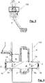
- Fig. 4 shows an example of an implementation of the invention.
- Fig. 4 is a cross section of the area highlighted in a box of the pedal group 100 shown in the Fig. 3 .
Abstract
Description
- The invention relates to a pedal group, such as a brake pedal group of a vehicle, which in an assembled position comprises a pedal body joined to a pedal shaft, the free ends of which are introduced into plain bearings, each one of which is housed in a support hole of a pedal support.
- Through patent document
DE 102004018266 , a break pedal group is known that comprises a pedal support with two lateral holes between which a pedal shaft extends to which a pedal body is integrally joined. - A characteristic of the invention proposed in
DE 102004018266 is that the pedal support comprises extensions that determine stops between which the pedal body may be arranged with a gap in an assembled position and which, due to butting against the pedal body, prevent axial movements of the pedal shaft that may cause one of the free ends thereof to be released from the associated lateral hole of the pedal support. - For the snug housing of each free end of the pedal shaft in the corresponding lateral hole of the pedal support, the use of plain bearings is proposed, which carry out the function of bearings, each one of which is snugly inserted in each lateral hole of the pedal support and into which, in an assembled position of the pedal group, the free ends of the pedal shaft are introduced.
- The extensions that determine the stops for limiting the axial movement of the pedal shaft are configured to butt against the pedal body when the pedal body takes an angular position with respect to the pedal support within a pre-established angle range, which includes the different angular positions the pedal body can take during the operation thereof once the pedal group is mounted in the vehicle and coupled to the brake mechanism. The aforementioned extensions ensure a retention of the pedal body that prevents the pedal from losing functionality even in the case that the bearings of the pedal are removed. It is impossible to remove the pedal shaft from the position thereof inside the lateral holes of the pedal support when the pedal is in an operative position.
- These extensions that determine the stops that limit the axial movement of the pedal shaft in the previously mentioned conditions do not prevent said axial movement in other angular positions outside of the pre-established angle range for the same. Advantageously, this allows an assembly phase of the pedal group to be carried out in a simple way, arranging the pedal body in one of said angular positions outside of the angle range associated with the normal operation of the pedal, first inserting a free end of the pedal shaft in a lateral hole of the pedal support and moving it until the other free end of the pedal shaft is aligned with the other lateral hole, then pulling back the pedal shaft in the opposite direction, inserting it at least partially in the aforementioned other lateral hole. Once this assembly phase of the pedal body in the support is finished, the pedal body is rotated, situating it in a working or operative position, such that the extensions of the pedal support prevent the pedal shaft from being extracted in the previously described way.
- Furthermore, the proposal according to
DE 102004018266 envisages the plain bearings being provided with a non-return step on the outside thereof, in the proximity of the mouth thereof which, in the operative position of the pedal group assembly rests on the inner edge of the associated support hole of the pedal support wherein the same are housed, and which prevent the plain bearings from being extracted from the aforementioned hole in the direction towards the outside of the pedal support. The non-return step has a general configuration of an arrowhead allowing for the introduction of the aforementioned plain bearings in the corresponding lateral holes of the pedal support from the outside, the mouth of the plain bearings slightly deforming towards the inside until the inner edge of these lateral holes goes beyond the non-return step, automatically restoring the original form of the mouth of the plain bearings, the non-return steps being supported on the inner edge of the lateral holes. - Although this characteristic should contribute to avoiding the extraction of the pedal shaft from the lateral holes even when the pedal body takes an angular position outside of the pre-established angle range for the operation thereof, in practice it has been demonstrated that providing these non-return steps is not enough to guarantee the extraction of the pedal shaft; or does not guarantee a sufficient retention of the pedal shaft from a possible lateral force that complies with the required safety conditions.
- In effect, it could be that after the assembly phase of the pedal group and before arranging the pedal body in an angular position within the pre-established angle position, being before or when the pedal group is mounted in the vehicle and is coupled to the brake mechanism, the pedal group may receive a blow, may fall or receive an impact significant enough so that the force of the pedal shaft on the plain bearing could either cause the plain bearing to break or cause a plastic deformation of the aforementioned plain bearing. For example, tests performed on commercial pedal groups have shown that subjecting the pedal axis to forces similar to 1000N, a force equivalent to the impact generated by a fall of the assembly from a height of 200 mm, can be enough to break the plain bearings.
- Thus, since the breakage of a plain bearing is perceptible by mere visual examination and allows the pedal group to be removed from the assembly line or from the supply line, the occasional plastic deformation of the plain bearing, for example of the bottom that receives the pressure of the free end of the pedal or of the non-return step, is not easily identifiable and can lead to the assembly of a defective pedal group in a vehicle.
- One aim of the present invention is a pedal group that can overcome these drawbacks.
- The pedal group proposed to solve the previously mentioned drawbacks comprises, in an assembled position, a pedal body joined to a pedal shaft the first and second free ends of which are introduced in plain bearings, each one of which is housed in a support hole of a pedal support, wherein said plain bearings have on the outer part thereof and on the area of the mouth thereof a non-return step which in an operative position of the pedal group rests against the inner edge of the support hole of the pedal support box, and which prevents the plain bearing from being extracted from the aforementioned hole in the direction towards the outside of the pedal support.
- The pedal group is characterized in that the pedal shaft has a bulge in the proximity of at least one of the first or second free ends thereof, which in the operative position of the group pedal assembly does not interfere with the mouth of the plain bearing in which said free end is introduced, but which in a forced assembly position, which comprises an undesired axial movement D of the pedal shaft, does interfere with the mouth of the aforementioned plain bearing, expanding it outwardly and, among other effects, anchoring the non-return step against the aforementioned inner edge of the support hole of the pedal support.
- One example of undesired movement is an impact caused by the accidental fall of the pedal group before the assembly thereof in a vehicle.
- Advantageously, as will be explained below, the interference between the bulge and the mouth of the bearing contributes to expanding the bushing inside the hole in which it is introduced, as it deforms the mouth of the bushing to ensure the anchoring of the non-return step of the bushing against the inner edge of the support hole of the pedal support. In a practical way, these effects contribute to the plain bearing being able to withstand greater stresses without breaking or becoming detached from the pedal support.
- The proposed solution is further compatible with pedal groups whose support is made up of one or two retaining extensions to act as a stop with the pedal body when the same takes an operative angular position, and therefore it is applicable to existing pedal supports.
- In a variant of the invention, the bulge is formed by a discreet projection, which is not substantially prolonged throughout the pedal shaft.
- In this case, the projection can be in the form of an annular projection. The projection, either in an annular shape or another shape, can be an integral part of the shaft or can be made up of an insert joined to the pedal shaft.
- The bulge can also be made up of a transition between two portions longitudinally contiguous of the pedal shaft, coaxial and with different cross sections.
- The pedal shaft can have a single bulge or two bulges, in this case the bulges of different nature being combined, each one intended to cooperate with a corresponding plain bearing. Then, each bulge will be located in the area of influence of a corresponding plain bearing.
- Thus, in an embodiment, in the proximity of a first free end, the pedal shaft has a first bulge formed by an annular projection, and in the proximity of a second free end, a second bulge formed by a transition between two longitudinal contiguous portions of the pedal shaft, coaxial and of different cross sections.
- According to an embodiment, the bearing, or if applicable the plain bearings in which one free end of the pedal shaft with the associated bulge is introduced, comprises a bottom with a support part, intended to receive the support of the aforementioned free end or tip of the pedal shaft, elastically deformable to absorb at least an axial movement d of the pedal shaft in the direction towards the pedal support, wherein d<D, this axial movement d being insufficient to produce the interference of the bulge with the mouth of the plain bearing. As a result, the expansion effect of the bushing will not be produced for small movements of the pedal shaft, for example less than 1 mm.
- The aforementioned support part of the bottom of the bushing can be in the form of a band, being made up of a strip of material that forms the bottom of the plain bearing that is joined by the ends thereof to the aforementioned bottom and which is slightly cambered towards the mouth of the plain bearing.
- The elastic deformation of the plain bearing allows part of the force to which the same is subjected to, by the pedal shaft moving, to be absorbed contributing to the elastic limit of the bushing reaching higher values of movement or of force in the axial direction said pedal shaft applies to the plain bearing.
- In an embodiment, in the strip of material that has the shape of a band, and which forms the support part, a central part acutely more arched is distinguished, on the top of which the free end of the pedal shaft introduced in the plain bearing rests. This allows for a particularly advantageous distribution of force applied to the bottom of the bearing.
- The distance D is preferably comprised between 0.75 and 1.5 mm. It is envisaged that the distance d is at least 60% of the distance D.
- In one variant of the invention, as was previously mentioned, the pedal support can comprise at least an extension that acts as a limit stop of axial movement of the pedal shaft by contact with the pedal body when the same takes an angular position within a pre-established range, inside of which the pedal is intended to be able to operate to carry out the function thereof.
-
-
Fig. 1 shows a schematic figure representative of the current state of the art; -
Fig. 2 is a schematic figure of the proposal according to the invention; -
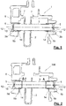
Fig. 3 is a perspective view of a pedal group according to the invention; -
Fig. 4 is a cross section view of the highlighted part in the box ofFig. 3 ; -
Fig. 5 to 7 are perspective, plan and cross-sectional views of a plain bearing of a pedal group according to a variant of the invention; -
Fig. 8 is a perspective view of a pedal group according to a variant of the invention; -
Figs. 9 and 10 are a sequence that schematically shows the effect that is produced in the pedal group of the invention when the pedal shaft is axially moved a distance D; and -
Fig. 11 is a graph that compares the behaviour of a pedal group according to the state of the art and of a pedal group according to the invention when the pedal shaft is subjected to a force that moves it axially. -
Fig. 1 schematically shows apedal group 1 representative of the current state of the art. Specifically,Fig. 1 illustrates abrake pedal group 1 that comprises apedal support 6 with twolateral holes 5 between which apedal shaft 3 extends to which apedal body 2 is integrally joined. - The
pedal support 6 comprisesextensions 7 that determine stops, between which thepedal body 2 is arranged with a gap when the same takes on an angular position within a pre-established angle range for the operation thereof. Outside of this angle range the axial movement of thepedal shaft 3 is dependent on the anchoring provided byplain bearings 10 housed in the lateral holes and inside of which thefree ends pedal shaft 3 are inserted. For this purpose, theseplain bearings 10 comprise anon-return step 14 in the proximity of the mouth thereof which rests against theinner edge 5b of theseholes 5. This anchoring, as was previously mentioned, is proven to be insufficient or unsafe when the pedal body is subjected to specific outer forces that tend to move the same axially. -
Fig. 2 shows apedal group 100 similar to that ofFig. 1 , illustrating thepedal body 2 in an angular, non-operative position, such that it does not interfere with theextensions 7 in the case of thepedal shaft 3 moving axially. In this case, however, thepedal shaft 3 has or has been provided with bulges A near thefree ends pedal shaft 3, will interfere with the mouth of the nearbyplain bearing 10, expanding it outwards, and, among other effects, ensuring the anchoring of thenon-return step 14 in the aforementionedinner edge 5b of thesupport hole 5 of thepedal support 6. As will be further explained in greater detail below, the expansion of the plain bearing 10 in this anchoring zone contributes in a practical way to reducing the concentration of forces that the free end of thepedal shaft 3 will exert on thebottom 12 of the plain bearing 10, notably increasing the resistance of this component to the deterioration or breakage thereof. - In order to maintain the advantages offered by a pedal group such as that of
Fig. 1 , with regard to the assembly phase of the pedal group, the bulges A will be dimensioned such that they do not prevent the introduction of thefree ends pedal shaft 3 in theholes 5, or at least one of thesefree ends holes 5 and, specifically, in the firstlateral hole 5 in which a firstfree end pedal shaft 3 will be introduced and will be positioned to align the second free end, the other of 3a or 3b, of thepedal shaft 3 with the otherlateral hole 5 of thepedal support 6 in which it will be introduced, this second free end then partially pulling back the first free end of thepedal shaft 3 of the firstlateral hole 5. As a result, at least one of the bulges A will be dimensioned so that the cross section of thepedal shaft 3 in this point can be introduced in the correspondinglateral hole 5. -
Fig. 4 shows an example of an implementation of the invention.Fig. 4 is a cross section of the area highlighted in a box of thepedal group 100 shown in theFig. 3 . - The
pedal group 100 ofFig. 4 mounts apedal shaft 3 such as that ofFig. 8 , made from an essentially cylindrical piece of steel, the different qualities able to be, for example, C8, C10 or C45, according to standard DIN EN 10263:2. Thispedal shaft 3 comprises a central portion on which thepedal body 2 will adjust and at each side of which thepedal shaft 3 extends to the free ends 3a and 3b thereof. In the proximity of thefree end 3a, a bulge A formed by anannular projection 20 is distinguished; while in the proximity of thefree end 3b another bulge A' is distinguished, formed in this case by a transition between two longitudinalcontiguous portions pedal shaft 3, coaxial and with different cross sections, specifically with different diameters. - Each one of these bulges A and A' is intended to cooperate with the
mouth 11 of the nearby plain bearing 10 if thepedal shaft 3 moves axially a distance D, starting from a centred position. - The
same pedal group 100 ofFig. 4 mountsplain bearings 10 as is shown inFigs. 5 to 7 . The example is aplain bearing 10 of a single piece made of plastic material, such as POM+MoS2 (Polyoxymethylene with Molybdenum Disulfide) and generally cylindrical with a bottom 12, the characteristics of which will be described below. - Conventionally, the
bearing 10, in the proximity of themouth 11 and outer portion thereof, comprises a sort ofnon-return step 14, essentially annular, the continuity of which is interrupted byslots 17 that extend in an axial direction from the edge of themouth 11 and which allow for the expansion of saidmouth 11 when the same goes over the bulges A or A', that is when the bulges A or A' push from inside and outwardly in the area of theplain bearing 10 with thenon-return step 14. - It must be noted that the edge of the
mouth 11 of theplain bearing 10 has a slightly reduced thickness with respect to the body of theplain bearing 10 and is configured in longitudinal cross section in the shape of an arrowhead to facilitate the introduction of theplain bearing 10 in thelateral hole 5 of thepedal support 6 from the outside. Inside, from the edge and in the direction toward the bottom 12 of theplain bearing 10, the arrowhead has aramp 13a intended to arrange the apex of the arrowhead sufficiently separated from the outer contour of thepedal shaft 3 to facilitate the introduction of the bulge A or A' in themouth 11 of theplain bearing 10, for the purposes of expanding it, when an axial movement of thepedal shaft 3 of a sufficient magnitude is produced. - As such, at the bottom 12 of the
plain bearing 10 referred to, the same comprises two essentially straight andparallel slots 16 that together determine asupport part 13, intended to receive the support of afree end pedal shaft 3, which is elastically deformable to absorb an axial movement d of thepedal shaft 3 in the direction towards the outside of thepedal support 6, at least while the d<D relation is complied with. This elastic deformation will even be able to continue in case the movement is greater than the distance D. - As shown by
Fig. 7 , in the example, the support part has the form of a band, and is made up of a strip of material that forms the bottom 12 of theplain bearing 10 that is joined by theends aforementioned bottom 12. Thesupport part 13 is, in the example, slightly cambered toward themouth 11 of theplain bearing 10 and in the same acentral part 13c acutely more arched is distinguished, on the top of which the free end of thepedal shaft 3 introduced in theplain bearing 10 rests. In an assembled position, the free ends 3a and 3b of thepedal shaft 3 can lightly rest against thesupport parts 13 of theplain bearings 10 for the purposes of eliminating an undesired gap between thepedal shaft 3 and thepedal support 6. In other words, it is envisaged that in an assembled position bothfree ends pedal shaft 3 touch or elastically deform thesupport part 13 of the associatedplain bearings 10. Alternatively, it can be seen that in an assembled position, there is a gap between thepedal shaft 3 and thesupport parts 13 that on each side of the shaft are provided by theplain bearings 10. - In any case, in a variant of interest, the arrangement of the bulges A and A' in the
pedal shaft 3 are selected according to the configuration of theplain bearings 10 so that the interference between both does not occur until thepedal shaft 3 resting against a bottom 12 of aplain bearing 10 has been moved from a centred or nominal position in the direction toward said bottom 12 a distance D, in the example, of 1 mm. - The functioning of the
pedal group 100 until the same achieves a forced assembled position which comprises the aforementioned axial movement D in the same direction of thepedal shaft 3 is the following: - Starting from the position illustrated in
Fig. 9 , which corresponds to an assembly position under non-forced conditions, by thepedal shaft 3 moving in the direction indicated by the arrow in a first phase of movement, thefree end 3b of the pedal shaft, by contact against thesupport part 13 of the bottom 12 of theplain bearing 10, will elastically deform said support part, the movement d of thepedal shaft 13 absorbing this deformation, reducing the axial stretching forces to which theplain bearing 10 would be subjected in the case of having a rigid bottom 12; - By the
pedal shaft 3 continuing with the movement thereof and reaching the movement distance D, the bulge A' contacts the inner part of themouth 11 of theplain bearing 10, as shown inFig. 10 ; - Once this point is reached, continuing with the movement of the
pedal shaft 3, the bulge A' will expand themouth 11 of the plain bearing against the walls of thehole 5 in which theplain bearing 10 is housed, to a greater extent the closer the bulge A' moves to theinner edge 5b of thehole 5. Likewise, the bulge of the outermost edge of themouth 11 ensures the anchoring of thenon-return step 14 against saidinner edge 5b of thehole 5. Note that although thefree end 3b of thepedal shaft 3 will continue to exert pressure on thesupport part 13 of the bottom 12 of theplain bearing 10, this bottom 12 will not be that which absorbs all of the force of the thrust of thepedal shaft 3 since the expansion of theplain bearing 10 and the friction of the same against the inside of thehole 5 will contribute in a notable way to withstanding this force. - To further enhance this effect, in the variant of the exemplified invention, the edge of the free ends 3a and 3b of the
pedal shaft 3 are machined to provide it with a morepronounced chamfer 3d. In the present case, the chamfered portion is greater than it ordinarily is, the portion of thepedal shaft 3 chamfered at a length L (seeFig. 8 ) of approximately 2 mm, and the inclination of the chamfer having been chosen at 45° with respect to the longitudinal axis of thepedal shaft 3. - This
chamfer 3d reduces the contact surface of thepedal shaft 3 with the bottom 12 of theplain bearing 10 in a non-forced situation (seeFig. 9 ), allowing a greater deformation of the latter before the tip of thepedal shaft 3 rests against a non-elastic part, devoid of the band, of theplain bearing 10, as illustrated inFig. 10 . - On the one hand, this deformation allows for the assembly of the plain bearing around the
pedal shaft 3, a situation for which thenon-return step 14 must exceed theinner edge 5b of thecorresponding support hole 5 and, on the other hand, ensures that an exceedingly rigid interference between the tip of thepedal shaft 3 and the bottom 12 of theplain bearing 10 prevents the expansion of theplain bearing 10 toward the outside in the area of themouth 11 thereof by the pressure of the bulge A or A' from happening, or from happening in an undesired way. -
Fig. 11 shows the behaviour of plain bearings in combination with a conventional pedal shaft, scenario C in dashed lines, and in combination with a modified pedal shaft with bulges according to the invention, scenario D in a continuous line, in this second case the plain bearing also being provided with a bottom with an elastically deformable support part in the previously described form referring toFigs. 8, 9 and 10 . - In
Fig. 11 the different behaviour between both scenarios C and D can be deduced when an incremental force is applied, especially when 1000N is reached, a situation in which the plain bearing in conventional scenario C escapes from the hole in which it is inserted because the small portion of material that makes up the non-return step gives way and/or the plain bearing will be completely plastically deformed until it most likely breaks. On the other hand, the plain bearing in scenario D, according to the invention, by the effect of the chamfer, the pedal shaft will continue to elastically deform the plain bearing but in a simultaneous fashion said plain bearing will expand at the area of the mouth thereof, ensuring the anchoring of the non-return step thereof and crushing the body of the plain bearing against the inside of the hole, preventing the same from exiting the position thereof until the plain bearing breaks either at the bottom thereof or at the anchoring zone, but once a retaining force of approximately 2000N is reached, which doubles the conventional value.
Claims (11)
- A pedal group (100), such as a brake pedal group of a vehicle, which comprises, in an assembly position, a pedal body (2) joined to a pedal shaft (3) the first and second free ends (3a, 3b) of which are introduced in plain bearings (10) each one of which is housed in a support hole (5) of a pedal support (6), wherein said plain bearings (10) have on the outer part thereof and in the area of the mouth (11) thereof a non-return step (14) which in an operative position of the pedal group rests against the inner edge (5b) of the support hole (5) of the pedal support (6), and which prevents the plain bearing from being extracted from the aforementioned hole in the direction towards the outside of the pedal support, the pedal group being characterized in that the pedal shaft (3) has a bulge (A or A') in the proximity of at least one of the first or second free ends (3a, 3b) which- in the operative position of the pedal group assembly, does not interfere with the mouth (11) of the plain bearing (10) in which said free end (3a, 3b) is introduced, but which- in a forced assembly position which comprises an undesired axial movement D of the pedal shaft (3) interferes with the mouth (11) of the aforementioned plain bearing, expanding it towards the outside, among other effects anchoring the non-return step (14) against the aforementioned inner edge (5b) of the support hole (5) of the pedal support (6).
- The pedal group (100) according to claim 1, characterized in that the bulge (A) is formed by a discreet projection (20) that is not substantially extended along the pedal shaft (3).
- The pedal group (100) according to the preceding claim, characterized in that the bulge (A) is formed by an annular projection (20).
- The pedal group (100) according to claim 1, characterized in that the bulge (A') is made up of a transition between two portions (33, 34) longitudinally contiguous of the pedal shaft (3), coaxial and with different cross sections.
- The pedal group (100) according to claims 3 and 4, the pedal shaft (3) of which, in the proximity of a first free end (3a), has a first bulge (A) formed by an annular projection (20); and in the proximity of a second free end (3b) has a second bulge (A') formed by a transition between two longitudinal contiguous portions (33, 34) of the pedal shaft (3), coaxial and with different cross sections.
- The pedal group (100) according to any one of the preceding claims, characterized in that the plain bearing (10), or if applicable the plain bearings, in which one free end (3a; 3b) of the pedal shaft (3) with the associated bulge (A or A') is introduced, comprises a bottom (12) with a support part (13), intended to receive the support of the aforementioned free end of the pedal shaft, elastically deformable to absorb at least an axial movement d of the pedal shaft (3) in the direction towards the pedal support (6), wherein d<D, this axial movement d being insufficient to produce the interference of the bulge (A or A') with the mouth (11) of the plain bearing (10).
- The pedal group (100) according to the preceding claim, characterized in that the support part (13) has the form of a band, and is made up of a strip of material that forms the bottom (12) of the plain bearing (10) that is joined by the ends (13a, 13b) thereof to the aforementioned bottom (12) and which is slightly cambered towards the mouth (11) of the plain bearing (10).
- The pedal group (100) according to the preceding claim, characterized in that in the strip of material that has the shape of a band, and which forms the support part (13), a central part (13c) is distinguished that is acutely more arched, on the top of which the free end of the pedal shaft (3) introduced in the plain bearing (10) rests.
- The pedal group (100) according to any one of the preceding claims, characterized in that the distance D is comprised between 0.75 mm and 1.5 mm.
- The pedal group (100) according to any one of the preceding claims, characterized in that the distance d is at least 60% of the distance D.
- The pedal group (100), according to any one of the preceding claims, characterized in that the pedal support (6) comprises at least an extension that acts as a limit stop (7) of the axial movement of the pedal shaft (3) by contact with the pedal body (2) only when the same takes an angular position within a pre-established range within which the pedal is intended to be able to operate to carry out the function thereof.
Priority Applications (2)
| Application Number | Priority Date | Filing Date | Title |
|---|---|---|---|
| ES18382532T ES2867386T3 (en) | 2018-07-17 | 2018-07-17 | A pedal group |
| EP18382532.2A EP3597493B1 (en) | 2018-07-17 | 2018-07-17 | A pedal group |
Applications Claiming Priority (1)
| Application Number | Priority Date | Filing Date | Title |
|---|---|---|---|
| EP18382532.2A EP3597493B1 (en) | 2018-07-17 | 2018-07-17 | A pedal group |
Publications (2)
| Publication Number | Publication Date |
|---|---|
| EP3597493A1 true EP3597493A1 (en) | 2020-01-22 |
| EP3597493B1 EP3597493B1 (en) | 2021-03-31 |
Family
ID=63108503
Family Applications (1)
| Application Number | Title | Priority Date | Filing Date |
|---|---|---|---|
| EP18382532.2A Active EP3597493B1 (en) | 2018-07-17 | 2018-07-17 | A pedal group |
Country Status (2)
| Country | Link |
|---|---|
| EP (1) | EP3597493B1 (en) |
| ES (1) | ES2867386T3 (en) |
Cited By (1)
| Publication number | Priority date | Publication date | Assignee | Title |
|---|---|---|---|---|
| CN111746481A (en) * | 2020-06-29 | 2020-10-09 | 重庆长安汽车股份有限公司 | Pedal assembly capable of automatically compensating clearance |
Citations (3)
| Publication number | Priority date | Publication date | Assignee | Title |
|---|---|---|---|---|
| US3299737A (en) * | 1964-09-30 | 1967-01-24 | Ford Motor Co | Retainer bushing |
| US5398569A (en) * | 1993-07-02 | 1995-03-21 | General Motors Corporation | Snap-in pedal |
| DE102004018266A1 (en) | 2004-04-15 | 2005-11-10 | Bayerische Motoren Werke Ag | Foot pedal and particularly an automobile brake pedal is mounted on a spindle so as to prevent sideways movement |
-
2018
- 2018-07-17 ES ES18382532T patent/ES2867386T3/en active Active
- 2018-07-17 EP EP18382532.2A patent/EP3597493B1/en active Active
Patent Citations (3)
| Publication number | Priority date | Publication date | Assignee | Title |
|---|---|---|---|---|
| US3299737A (en) * | 1964-09-30 | 1967-01-24 | Ford Motor Co | Retainer bushing |
| US5398569A (en) * | 1993-07-02 | 1995-03-21 | General Motors Corporation | Snap-in pedal |
| DE102004018266A1 (en) | 2004-04-15 | 2005-11-10 | Bayerische Motoren Werke Ag | Foot pedal and particularly an automobile brake pedal is mounted on a spindle so as to prevent sideways movement |
Cited By (1)
| Publication number | Priority date | Publication date | Assignee | Title |
|---|---|---|---|---|
| CN111746481A (en) * | 2020-06-29 | 2020-10-09 | 重庆长安汽车股份有限公司 | Pedal assembly capable of automatically compensating clearance |
Also Published As
| Publication number | Publication date |
|---|---|
| ES2867386T3 (en) | 2021-10-20 |
| EP3597493B1 (en) | 2021-03-31 |
Similar Documents
| Publication | Publication Date | Title |
|---|---|---|
| DK3060816T3 (en) | Expansion anchor with expansion sleeve with high strength sections | |
| EP1306573B1 (en) | Resilient bush and method of pressure-insertion of a resilient bush | |
| EP2153933A2 (en) | Rotor shaft and method of manufacturing the same | |
| EP3597493B1 (en) | A pedal group | |
| US20140147064A1 (en) | Radial foil bearing | |
| US7488112B2 (en) | Assembly arrangement between a bearing inner race and a journal, race and journal suitable for such an arrangement, and turbomachine fitted therewith | |
| US4775249A (en) | Plain bearing | |
| EP2592288A1 (en) | Ball joint and method for producing ball joint | |
| CN101607352A (en) | The device that uses with friction stir spot welding (FSSW) equipment | |
| EP3540251A1 (en) | Cylindrical roller bearing | |
| US11378105B2 (en) | Gas cylinder actuator with safety device for uncontrolled return of the piston-stem | |
| US10369620B2 (en) | Bearing pin upset method to retain high hardness pins | |
| EP3701158B1 (en) | Ball socket assembly and method of making | |
| EP3040569B1 (en) | Method for manufacturing shell-type needle bearing, and manufacturing jig used in manufacture of same | |
| US3345723A (en) | Dummy pin means and method for assembling needle bearings | |
| DE102014114140B4 (en) | Belt retractor with two-part tensioner wheel | |
| US1350245A (en) | Bearing | |
| KR101747417B1 (en) | Chock automatic clamp for rolling roll | |
| US11413990B2 (en) | Tube joints with consistent friction torque and no clearance gap | |
| EP3037632A1 (en) | Hydraulic lash adjuster | |
| KR101756542B1 (en) | Rolling bearing, Shield for rolling bearing and Method for assembling the same | |
| EP0672838A1 (en) | Blind rivet assembly | |
| EP4074990A1 (en) | Expansion anchor | |
| JP7175856B2 (en) | BALL SEAT, BALL JOINT AND METHOD OF MANUFACTURING BALL JOINT | |
| JPS5865318A (en) | Needle bearing |
Legal Events
| Date | Code | Title | Description |
|---|---|---|---|
| PUAI | Public reference made under article 153(3) epc to a published international application that has entered the european phase |
Free format text: ORIGINAL CODE: 0009012 |
|
| STAA | Information on the status of an ep patent application or granted ep patent |
Free format text: STATUS: THE APPLICATION HAS BEEN PUBLISHED |
|
| AK | Designated contracting states |
Kind code of ref document: A1 Designated state(s): AL AT BE BG CH CY CZ DE DK EE ES FI FR GB GR HR HU IE IS IT LI LT LU LV MC MK MT NL NO PL PT RO RS SE SI SK SM TR |
|
| AX | Request for extension of the european patent |
Extension state: BA ME |
|
| STAA | Information on the status of an ep patent application or granted ep patent |
Free format text: STATUS: REQUEST FOR EXAMINATION WAS MADE |
|
| 17P | Request for examination filed |
Effective date: 20200708 |
|
| RBV | Designated contracting states (corrected) |
Designated state(s): AL AT BE BG CH CY CZ DE DK EE ES FI FR GB GR HR HU IE IS IT LI LT LU LV MC MK MT NL NO PL PT RO RS SE SI SK SM TR |
|
| GRAP | Despatch of communication of intention to grant a patent |
Free format text: ORIGINAL CODE: EPIDOSNIGR1 |
|
| STAA | Information on the status of an ep patent application or granted ep patent |
Free format text: STATUS: GRANT OF PATENT IS INTENDED |
|
| RIC1 | Information provided on ipc code assigned before grant |
Ipc: B60T 7/06 20060101AFI20201022BHEP Ipc: G05G 1/44 20080401ALI20201022BHEP |
|
| INTG | Intention to grant announced |
Effective date: 20201106 |
|
| GRAS | Grant fee paid |
Free format text: ORIGINAL CODE: EPIDOSNIGR3 |
|
| GRAA | (expected) grant |
Free format text: ORIGINAL CODE: 0009210 |
|
| STAA | Information on the status of an ep patent application or granted ep patent |
Free format text: STATUS: THE PATENT HAS BEEN GRANTED |
|
| AK | Designated contracting states |
Kind code of ref document: B1 Designated state(s): AL AT BE BG CH CY CZ DE DK EE ES FI FR GB GR HR HU IE IS IT LI LT LU LV MC MK MT NL NO PL PT RO RS SE SI SK SM TR |
|
| REG | Reference to a national code |
Ref country code: GB Ref legal event code: FG4D Ref country code: CH Ref legal event code: EP |
|
| REG | Reference to a national code |
Ref country code: AT Ref legal event code: REF Ref document number: 1376590 Country of ref document: AT Kind code of ref document: T Effective date: 20210415 |
|
| REG | Reference to a national code |
Ref country code: DE Ref legal event code: R096 Ref document number: 602018014694 Country of ref document: DE |
|
| REG | Reference to a national code |
Ref country code: IE Ref legal event code: FG4D |
|
| REG | Reference to a national code |
Ref country code: LT Ref legal event code: MG9D |
|
| PG25 | Lapsed in a contracting state [announced via postgrant information from national office to epo] |
Ref country code: BG Free format text: LAPSE BECAUSE OF FAILURE TO SUBMIT A TRANSLATION OF THE DESCRIPTION OR TO PAY THE FEE WITHIN THE PRESCRIBED TIME-LIMIT Effective date: 20210630 Ref country code: FI Free format text: LAPSE BECAUSE OF FAILURE TO SUBMIT A TRANSLATION OF THE DESCRIPTION OR TO PAY THE FEE WITHIN THE PRESCRIBED TIME-LIMIT Effective date: 20210331 Ref country code: HR Free format text: LAPSE BECAUSE OF FAILURE TO SUBMIT A TRANSLATION OF THE DESCRIPTION OR TO PAY THE FEE WITHIN THE PRESCRIBED TIME-LIMIT Effective date: 20210331 Ref country code: NO Free format text: LAPSE BECAUSE OF FAILURE TO SUBMIT A TRANSLATION OF THE DESCRIPTION OR TO PAY THE FEE WITHIN THE PRESCRIBED TIME-LIMIT Effective date: 20210630 |
|
| PG25 | Lapsed in a contracting state [announced via postgrant information from national office to epo] |
Ref country code: SE Free format text: LAPSE BECAUSE OF FAILURE TO SUBMIT A TRANSLATION OF THE DESCRIPTION OR TO PAY THE FEE WITHIN THE PRESCRIBED TIME-LIMIT Effective date: 20210331 Ref country code: RS Free format text: LAPSE BECAUSE OF FAILURE TO SUBMIT A TRANSLATION OF THE DESCRIPTION OR TO PAY THE FEE WITHIN THE PRESCRIBED TIME-LIMIT Effective date: 20210331 Ref country code: LV Free format text: LAPSE BECAUSE OF FAILURE TO SUBMIT A TRANSLATION OF THE DESCRIPTION OR TO PAY THE FEE WITHIN THE PRESCRIBED TIME-LIMIT Effective date: 20210331 |
|
| REG | Reference to a national code |
Ref country code: NL Ref legal event code: MP Effective date: 20210331 |
|
| REG | Reference to a national code |
Ref country code: AT Ref legal event code: MK05 Ref document number: 1376590 Country of ref document: AT Kind code of ref document: T Effective date: 20210331 |
|
| REG | Reference to a national code |
Ref country code: ES Ref legal event code: FG2A Ref document number: 2867386 Country of ref document: ES Kind code of ref document: T3 Effective date: 20211020 |
|
| PG25 | Lapsed in a contracting state [announced via postgrant information from national office to epo] |
Ref country code: LT Free format text: LAPSE BECAUSE OF FAILURE TO SUBMIT A TRANSLATION OF THE DESCRIPTION OR TO PAY THE FEE WITHIN THE PRESCRIBED TIME-LIMIT Effective date: 20210331 Ref country code: EE Free format text: LAPSE BECAUSE OF FAILURE TO SUBMIT A TRANSLATION OF THE DESCRIPTION OR TO PAY THE FEE WITHIN THE PRESCRIBED TIME-LIMIT Effective date: 20210331 Ref country code: CZ Free format text: LAPSE BECAUSE OF FAILURE TO SUBMIT A TRANSLATION OF THE DESCRIPTION OR TO PAY THE FEE WITHIN THE PRESCRIBED TIME-LIMIT Effective date: 20210331 Ref country code: NL Free format text: LAPSE BECAUSE OF FAILURE TO SUBMIT A TRANSLATION OF THE DESCRIPTION OR TO PAY THE FEE WITHIN THE PRESCRIBED TIME-LIMIT Effective date: 20210331 Ref country code: SM Free format text: LAPSE BECAUSE OF FAILURE TO SUBMIT A TRANSLATION OF THE DESCRIPTION OR TO PAY THE FEE WITHIN THE PRESCRIBED TIME-LIMIT Effective date: 20210331 Ref country code: AT Free format text: LAPSE BECAUSE OF FAILURE TO SUBMIT A TRANSLATION OF THE DESCRIPTION OR TO PAY THE FEE WITHIN THE PRESCRIBED TIME-LIMIT Effective date: 20210331 |
|
| PG25 | Lapsed in a contracting state [announced via postgrant information from national office to epo] |
Ref country code: PT Free format text: LAPSE BECAUSE OF FAILURE TO SUBMIT A TRANSLATION OF THE DESCRIPTION OR TO PAY THE FEE WITHIN THE PRESCRIBED TIME-LIMIT Effective date: 20210802 Ref country code: PL Free format text: LAPSE BECAUSE OF FAILURE TO SUBMIT A TRANSLATION OF THE DESCRIPTION OR TO PAY THE FEE WITHIN THE PRESCRIBED TIME-LIMIT Effective date: 20210331 Ref country code: RO Free format text: LAPSE BECAUSE OF FAILURE TO SUBMIT A TRANSLATION OF THE DESCRIPTION OR TO PAY THE FEE WITHIN THE PRESCRIBED TIME-LIMIT Effective date: 20210331 Ref country code: SK Free format text: LAPSE BECAUSE OF FAILURE TO SUBMIT A TRANSLATION OF THE DESCRIPTION OR TO PAY THE FEE WITHIN THE PRESCRIBED TIME-LIMIT Effective date: 20210331 Ref country code: IS Free format text: LAPSE BECAUSE OF FAILURE TO SUBMIT A TRANSLATION OF THE DESCRIPTION OR TO PAY THE FEE WITHIN THE PRESCRIBED TIME-LIMIT Effective date: 20210731 |
|
| REG | Reference to a national code |
Ref country code: DE Ref legal event code: R097 Ref document number: 602018014694 Country of ref document: DE |
|
| PG25 | Lapsed in a contracting state [announced via postgrant information from national office to epo] |
Ref country code: DK Free format text: LAPSE BECAUSE OF FAILURE TO SUBMIT A TRANSLATION OF THE DESCRIPTION OR TO PAY THE FEE WITHIN THE PRESCRIBED TIME-LIMIT Effective date: 20210331 Ref country code: AL Free format text: LAPSE BECAUSE OF FAILURE TO SUBMIT A TRANSLATION OF THE DESCRIPTION OR TO PAY THE FEE WITHIN THE PRESCRIBED TIME-LIMIT Effective date: 20210331 |
|
| PLBE | No opposition filed within time limit |
Free format text: ORIGINAL CODE: 0009261 |
|
| STAA | Information on the status of an ep patent application or granted ep patent |
Free format text: STATUS: NO OPPOSITION FILED WITHIN TIME LIMIT |
|
| REG | Reference to a national code |
Ref country code: CH Ref legal event code: PL |
|
| 26N | No opposition filed |
Effective date: 20220104 |
|
| PG25 | Lapsed in a contracting state [announced via postgrant information from national office to epo] |
Ref country code: MC Free format text: LAPSE BECAUSE OF FAILURE TO SUBMIT A TRANSLATION OF THE DESCRIPTION OR TO PAY THE FEE WITHIN THE PRESCRIBED TIME-LIMIT Effective date: 20210331 |
|
| REG | Reference to a national code |
Ref country code: BE Ref legal event code: MM Effective date: 20210731 |
|
| PG25 | Lapsed in a contracting state [announced via postgrant information from national office to epo] |
Ref country code: LI Free format text: LAPSE BECAUSE OF NON-PAYMENT OF DUE FEES Effective date: 20210731 Ref country code: CH Free format text: LAPSE BECAUSE OF NON-PAYMENT OF DUE FEES Effective date: 20210731 |
|
| PG25 | Lapsed in a contracting state [announced via postgrant information from national office to epo] |
Ref country code: IS Free format text: LAPSE BECAUSE OF FAILURE TO SUBMIT A TRANSLATION OF THE DESCRIPTION OR TO PAY THE FEE WITHIN THE PRESCRIBED TIME-LIMIT Effective date: 20210731 Ref country code: LU Free format text: LAPSE BECAUSE OF NON-PAYMENT OF DUE FEES Effective date: 20210717 |
|
| PG25 | Lapsed in a contracting state [announced via postgrant information from national office to epo] |
Ref country code: IE Free format text: LAPSE BECAUSE OF NON-PAYMENT OF DUE FEES Effective date: 20210717 Ref country code: BE Free format text: LAPSE BECAUSE OF NON-PAYMENT OF DUE FEES Effective date: 20210731 |
|
| PG25 | Lapsed in a contracting state [announced via postgrant information from national office to epo] |
Ref country code: CY Free format text: LAPSE BECAUSE OF FAILURE TO SUBMIT A TRANSLATION OF THE DESCRIPTION OR TO PAY THE FEE WITHIN THE PRESCRIBED TIME-LIMIT Effective date: 20210331 |
|
| PG25 | Lapsed in a contracting state [announced via postgrant information from national office to epo] |
Ref country code: HU Free format text: LAPSE BECAUSE OF FAILURE TO SUBMIT A TRANSLATION OF THE DESCRIPTION OR TO PAY THE FEE WITHIN THE PRESCRIBED TIME-LIMIT; INVALID AB INITIO Effective date: 20180717 Ref country code: GR Free format text: LAPSE BECAUSE OF FAILURE TO SUBMIT A TRANSLATION OF THE DESCRIPTION OR TO PAY THE FEE WITHIN THE PRESCRIBED TIME-LIMIT Effective date: 20210331 |
|
| PGFP | Annual fee paid to national office [announced via postgrant information from national office to epo] |
Ref country code: IT Payment date: 20230629 Year of fee payment: 6 Ref country code: GB Payment date: 20230615 Year of fee payment: 6 Ref country code: ES Payment date: 20230817 Year of fee payment: 6 |
|
| PGFP | Annual fee paid to national office [announced via postgrant information from national office to epo] |
Ref country code: FR Payment date: 20230724 Year of fee payment: 6 Ref country code: DE Payment date: 20230720 Year of fee payment: 6 |
|
| PG25 | Lapsed in a contracting state [announced via postgrant information from national office to epo] |
Ref country code: MK Free format text: LAPSE BECAUSE OF FAILURE TO SUBMIT A TRANSLATION OF THE DESCRIPTION OR TO PAY THE FEE WITHIN THE PRESCRIBED TIME-LIMIT Effective date: 20210331 |