EP3597442A1 - Light-emitting medium, forgery prevention medium, and method for determining authenticity of same - Google Patents
Light-emitting medium, forgery prevention medium, and method for determining authenticity of same Download PDFInfo
- Publication number
- EP3597442A1 EP3597442A1 EP18766825.6A EP18766825A EP3597442A1 EP 3597442 A1 EP3597442 A1 EP 3597442A1 EP 18766825 A EP18766825 A EP 18766825A EP 3597442 A1 EP3597442 A1 EP 3597442A1
- Authority
- EP
- European Patent Office
- Prior art keywords
- light
- emitting
- region
- emitting region
- fluorescent substance
- Prior art date
- Legal status (The legal status is an assumption and is not a legal conclusion. Google has not performed a legal analysis and makes no representation as to the accuracy of the status listed.)
- Granted
Links
Images





Classifications
-
- B—PERFORMING OPERATIONS; TRANSPORTING
- B42—BOOKBINDING; ALBUMS; FILES; SPECIAL PRINTED MATTER
- B42D—BOOKS; BOOK COVERS; LOOSE LEAVES; PRINTED MATTER CHARACTERISED BY IDENTIFICATION OR SECURITY FEATURES; PRINTED MATTER OF SPECIAL FORMAT OR STYLE NOT OTHERWISE PROVIDED FOR; DEVICES FOR USE THEREWITH AND NOT OTHERWISE PROVIDED FOR; MOVABLE-STRIP WRITING OR READING APPARATUS
- B42D25/00—Information-bearing cards or sheet-like structures characterised by identification or security features; Manufacture thereof
- B42D25/40—Manufacture
- B42D25/45—Associating two or more layers
-
- B—PERFORMING OPERATIONS; TRANSPORTING
- B41—PRINTING; LINING MACHINES; TYPEWRITERS; STAMPS
- B41M—PRINTING, DUPLICATING, MARKING, OR COPYING PROCESSES; COLOUR PRINTING
- B41M3/00—Printing processes to produce particular kinds of printed work, e.g. patterns
- B41M3/14—Security printing
- B41M3/144—Security printing using fluorescent, luminescent or iridescent effects
-
- B—PERFORMING OPERATIONS; TRANSPORTING
- B41—PRINTING; LINING MACHINES; TYPEWRITERS; STAMPS
- B41M—PRINTING, DUPLICATING, MARKING, OR COPYING PROCESSES; COLOUR PRINTING
- B41M3/00—Printing processes to produce particular kinds of printed work, e.g. patterns
- B41M3/06—Veined printings; Fluorescent printings; Stereoscopic images; Imitated patterns, e.g. tissues, textiles
-
- B—PERFORMING OPERATIONS; TRANSPORTING
- B42—BOOKBINDING; ALBUMS; FILES; SPECIAL PRINTED MATTER
- B42D—BOOKS; BOOK COVERS; LOOSE LEAVES; PRINTED MATTER CHARACTERISED BY IDENTIFICATION OR SECURITY FEATURES; PRINTED MATTER OF SPECIAL FORMAT OR STYLE NOT OTHERWISE PROVIDED FOR; DEVICES FOR USE THEREWITH AND NOT OTHERWISE PROVIDED FOR; MOVABLE-STRIP WRITING OR READING APPARATUS
- B42D25/00—Information-bearing cards or sheet-like structures characterised by identification or security features; Manufacture thereof
- B42D25/30—Identification or security features, e.g. for preventing forgery
- B42D25/351—Translucent or partly translucent parts, e.g. windows
-
- B—PERFORMING OPERATIONS; TRANSPORTING
- B42—BOOKBINDING; ALBUMS; FILES; SPECIAL PRINTED MATTER
- B42D—BOOKS; BOOK COVERS; LOOSE LEAVES; PRINTED MATTER CHARACTERISED BY IDENTIFICATION OR SECURITY FEATURES; PRINTED MATTER OF SPECIAL FORMAT OR STYLE NOT OTHERWISE PROVIDED FOR; DEVICES FOR USE THEREWITH AND NOT OTHERWISE PROVIDED FOR; MOVABLE-STRIP WRITING OR READING APPARATUS
- B42D25/00—Information-bearing cards or sheet-like structures characterised by identification or security features; Manufacture thereof
- B42D25/30—Identification or security features, e.g. for preventing forgery
- B42D25/36—Identification or security features, e.g. for preventing forgery comprising special materials
- B42D25/378—Special inks
- B42D25/382—Special inks absorbing or reflecting infrared light
-
- B—PERFORMING OPERATIONS; TRANSPORTING
- B42—BOOKBINDING; ALBUMS; FILES; SPECIAL PRINTED MATTER
- B42D—BOOKS; BOOK COVERS; LOOSE LEAVES; PRINTED MATTER CHARACTERISED BY IDENTIFICATION OR SECURITY FEATURES; PRINTED MATTER OF SPECIAL FORMAT OR STYLE NOT OTHERWISE PROVIDED FOR; DEVICES FOR USE THEREWITH AND NOT OTHERWISE PROVIDED FOR; MOVABLE-STRIP WRITING OR READING APPARATUS
- B42D25/00—Information-bearing cards or sheet-like structures characterised by identification or security features; Manufacture thereof
- B42D25/30—Identification or security features, e.g. for preventing forgery
- B42D25/36—Identification or security features, e.g. for preventing forgery comprising special materials
- B42D25/378—Special inks
- B42D25/387—Special inks absorbing or reflecting ultraviolet light
-
- G—PHYSICS
- G07—CHECKING-DEVICES
- G07D—HANDLING OF COINS OR VALUABLE PAPERS, e.g. TESTING, SORTING BY DENOMINATIONS, COUNTING, DISPENSING, CHANGING OR DEPOSITING
- G07D7/00—Testing specially adapted to determine the identity or genuineness of valuable papers or for segregating those which are unacceptable, e.g. banknotes that are alien to a currency
- G07D7/06—Testing specially adapted to determine the identity or genuineness of valuable papers or for segregating those which are unacceptable, e.g. banknotes that are alien to a currency using wave or particle radiation
- G07D7/12—Visible light, infrared or ultraviolet radiation
- G07D7/1205—Testing spectral properties
Definitions
- the present invention relates to a light-emitting medium including a substrate and a light-emitting region, a forgery prevention medium, and a method for determining authenticity of the light-emitting medium.
- the fluorescent ink is an ink containing a fluorescent substance that is not substantially visually recognized under visible light, and is visually recognized when being irradiated with non-visible light (ultraviolet rays or infrared rays).
- fluorescent ink When using such fluorescent ink, it is possible to form a fluorescent image (light-emitting image), which appears only when the securities and the like are irradiated with non-visible light in a specific wavelength region, in the securities and the like. According to this, it is possible to prevent the securities from being easily forged with a general-purpose color printer or the like.
- articles including a forgery prevention countermeasure as described above mainly include various transparent media containing a polymer compound such as plastic.
- a polymer compound such as plastic.
- plastic currency instead of paper, transparent plastic currency, a transparent card, and the like can be exemplified.
- a plastic substrate that emits visually transparent fluorescence by adjusting a refractive index is disclosed (Patent Document 1).
- Patent Document 2 discloses a medium including a light-emitting image that is formed by using a first fluorescent ink and a second fluorescent ink.
- the first fluorescent ink and the second fluorescent ink are inks which are visually recognized as the same color under visible light and ultraviolet ray when being viewed with naked eyes, and are visually recognized as different colors when being viewed through a discrimination tool. According to this, it is difficult for the light-emitting image formed on the securities to be easily forged, and as a result, the forgery prevention effect due to the fluorescent inks is enhanced.
- Patent Document 2 it is necessary to prepare two kinds of tools including blacklight and a discrimination tool. Therefore, there is a demand for a medium capable of more easily realizing different light-emitting forms capable of being easily discriminated by using normal black light. In addition, the medium may also be used for purposes other than forgery prevention (authenticity determination).
- An object of the invention is to provide a light-emitting medium capable of realizing different light-emitting forms capable of being easily discriminated by using normal blacklight, a forgery prevention medium, and a method for determining authenticity of the light-emitting medium.
- the invention accomplishes the object by the following means for solving the problems. Note that, description will be made by applying reference numerals corresponding to an embodiment of the invention for easy understanding, but there is no limitation thereto.
- a light-emitting medium (1, 1A) including a substrate (2), and a first light-emitting region (3) and a second light-emitting region (4) disposed on both sides of the substrate (2).
- the substrate (2) includes a selective transmission layer through which non-visible light in a first wavelength region is transmitted, and non-visible light in a second wavelength region different from the first wavelength region is not substantially transmitted, and the first light-emitting region (3) and the second light-emitting region (4) contain a fluorescent substance that emits light when being irradiated with non-visible light in the first wavelength region and also emits light when being irradiated with non-visible light in the second wavelength region.
- the first light-emitting region (3) and the second light-emitting region (4) have shapes which at least partially do not overlap each other when viewed in a thickness direction (Z) of the substrate (2) through the substrate (2).
- the fluorescent substance of the first light-emitting region (3) and the fluorescent substance of the second light-emitting region (4) emit light which are visually recognized as different colors when being irradiated with non-visible light in the first wavelength region, and emit light which are visually recognized as different colors even when being irradiated with non-visible light in the second wavelength region.
- the first light-emitting region (3A) and the second light-emitting region (4A) show an incomplete shape only on one side, and in a state in which both the fluorescent substance of the first light-emitting region (3A) and the fluorescent substance of the second light-emitting region (4A) emit light, the first light-emitting region (3A) and the second light-emitting region (4A) show a complete shape on both sides.
- a forgery prevention medium to which the light-emitting medium according to any one of the first to fourth aspects is applied.
- a method for determining authenticity of the light-emitting medium includes: a preparation process of preparing a light-emitting medium (1, 1A); a first wavelength irradiation process of irradiating the light-emitting medium (1, 1A) with non-visible light in a first wavelength region to confirm light-emission of both of the fluorescent substance of the first light-emitting region (3) and the fluorescent substance of the second light-emitting region (4); a second wavelength irradiation process of irradiating the light-emitting medium (1, 1A) with non-visible light in a second wavelength region to confirm light-emission of only one on an irradiation source side between the fluorescent substance of the first light-emitting region (3) and the fluorescent substance of the second light-emitting region (4); and a determination process of determining that the light-emitting medium (1, 1A) is genuine when confirmation is obtained in
- a light-emitting medium capable of realizing different light-emitting forms capable of being easily discriminated by using normal blacklight, a forgery prevention medium, and a method for confirming the light-emitting medium.
- a light-emitting medium of the invention is applied to a forgery prevention medium.
- the forgery prevention medium include a cash card that is used in a bank or the like, a membership card that is used in a shop or the like, plastic paper money (resin sheet paper money), a data page of passport, and the like.
- the forgery prevention medium when being used as a cash card or a membership card, may be provided with an IC chip or a communication antenna that is used in individual authentication or the like, or may be provided with a printed layer that applies a pattern or the like to front and rear surfaces of the card, functional layers, and the like in addition to the configuration illustrated in Fig. 1 to be described later.
- the forgery prevention medium may be further provided with a forgery prevention configuration such as a water mark provided in typical paper money or the like.
- Fig. 1 is a view illustrating a forgery prevention medium 1 of a first embodiment as a light-emitting medium of the invention, and in Fig. 1 , (A) is a plan view and (B) is a cross-sectional view taken along line B-B in (A).
- Fig. 2 is a view illustrating a first printed layer 51 including a first light-emitting region 3 in the forgery prevention medium 1 of the first embodiment by virtually extracting the first printed layer 51, and in Fig. 2 , (A) is a plan view, and (B) is a rear view.
- Fig. 1 is a view illustrating a forgery prevention medium 1 of a first embodiment as a light-emitting medium of the invention, and in Fig. 1 , (A) is a plan view and (B) is a cross-sectional view taken along line B-B in (A).
- Fig. 2 is a view illustrating a first printed layer 51 including a first light-emit
- FIG. 3 is a view illustrating a second printed layer 52 including a second light-emitting region 4 in the forgery prevention medium 1 of the first embodiment by virtually extracting the second printed layer 52, and in Fig. 3 , (A) is a plan view, and (B) is a rear view.
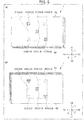
- Fig. 4 is a view illustrating a light-emitting form when the forgery prevention medium 1 of the first embodiment is irradiated with non-visible light in a first wavelength region, and in Fig. 4 , (A) is a plan view, and (B) is a rear view.
- FIG. 5 is a view illustrating a light-emitting form when the forgery prevention medium 1 of the first embodiment is irradiated with non-visible light in a second wavelength region, and in Fig. 5 , (A) is a plan view, and (B) is a rear view.
- an XYZ orthogonal coordinate system is provided for easy explanation and easy understanding.
- the coordinate system shows a right and left direction X (a left side: X1, and a right side: X2), a vertical direction Y (an upper side: Y1, and a lower side: Y2), and a thickness direction Z (a front (upper) side: Z1, and a rear (lower) side: Z2) on the basis of a state of Fig. 1 .
- a shape is appropriately simplified or deformed in accordance with the drawings. For example, in Fig.
- shapes of the first light-emitting region 3 and the second light-emitting region 4 are simplified, and the first light-emitting region 3 and the second light-emitting region 4 are illustrated in a rectangular shape.
- sizes of the first light-emitting region 3 and the second light-emitting region 4 are deformed, and the shapes of the first light-emitting region 3 and the second light-emitting region 4 are enlarged.
- the forgery prevention medium 1 is a sheet-shaped article having a rectangular shape in an XY plane, and is a laminated body in which a first transparent protective layer 61, the first printed layer 51 including the first light-emitting region 3, a substrate layer 2, the second printed layer 52 including the second light-emitting region 4, and a second transparent protective layer 62 are laminated in this order from the front side Z1 to the rear side Z2 in the thickness direction Z.
- the "first transparent protective layer 61" and the "second transparent protective layer 62" may be simply referred to as "transparent protective layer".
- first light-emitting region 3" and the “second light-emitting region 4" may be simply referred to as "light-emitting region”.
- first printed layer 51" and the “second printed layer 52" may be referred to as "printed layer”.
- the substrate layer 2 is a layer that becomes a substrate of the forgery prevention medium 1, and may be referred to as "substrate 2" in this specification.
- substrate 2 transparent polypropylene (PP), polyethylene terephthalate (PET), polycarbonate (PC), or the like with excellent printability and processability is used.
- PP polypropylene
- PET polyethylene terephthalate
- PC polycarbonate
- transparent represents that visible light is transmitted.
- a selective transmission property of the substrate layer 2 as one characteristic of the invention will be described later in detail.
- the substrate layer 2 is a layer having the highest rigidity, but a layer having further higher rigidity or a layer having a larger thickness may exist in the forgery prevention medium (light-emitting medium) 1 in addition to the substrate layer 2.
- the first printed layer 51 is formed on an upper surface of the substrate layer 2 through printing.
- a lower surface 512 of the first printed layer 51 is in contact with the upper surface of the substrate layer 2.
- the second printed layer 52 is formed on a lower surface of the substrate layer 2 through printing.
- An upper surface 521 of the second printed layer 52 is in contact with the lower surface of the substrate layer 2.
- Examples of the printing include silk screen printing, offset, gravure printing, and the like. It is preferable that an ink of the first printed layer 51 (excluding the first light-emitting region 3) and the second printed layer 52 (excluding the second light-emitting region 4) has a high light-shielding property of not allowing light to be transmitted therethrough (for example, an ink having a high shielding property at a white color).
- a partial region of an XY plane in the first printed layer 51 is set to a first window portion 513 that passes through the first printed layer 51 in a thickness direction Z.
- a partial region of an XY plane in the second printed layer 52 is set to a second window portion 523 that passes through the second printed layer 52 in the thickness direction Z.
- the region of the first window portion 513 is observed transparently. This is also true of the second printed layer 52.
- the "first window portion 513" and the "second window portion 523" may be referred to as "window portion”.
- an external shape of the first window portion 513 and an external shape of the second window portion 523 equal and match each other.
- an external shape of one side of the first window portion 513 and the second window portion 523 may be set to be larger than an external shape of the other side without limitation to the above-described mode.
- the window portion provided in each of the printed layers is a region in which printing is not performed to a part of the printed layer, that is, a region through which incident light can be transmitted, in accordance with an application mode of the forgery prevention medium 1, the window portion may be filled with a transparent material of a polycarbonate resin or the like, or a transparent member of the same resin or the like (polycarbonate resin or the like) may be disposed in the window portion (an application mode of the forgery prevention medium 1 will be described later).
- the first light-emitting region 3 is provided in the first window portion 513.
- the second light-emitting region 4 is provided in the second window portion 523.
- the first light-emitting region 3 and the second light-emitting region 4 are formed by printing (for example, offset) or applying an ink containing a fluorescent substance to at least a part of a position corresponding to the window portion of the substrate layer 2.
- the first light-emitting region 3 and the second light-emitting region 4 have transparency when light is not emitted.
- first light-emitting region 3 and the second light-emitting region 4 contain a fluorescent substance that emits visible light when being irradiated with non-visible light in a first wavelength region, and emits visible light even when being irradiated with non-visible light in a second wavelength region. Details of the fluorescent substance contained in the light-emitting region will be described later.
- the first light-emitting region 3 and the second light-emitting region 4 may be formed after printing the first printed layer 51 and the second printed layer 52 on the substrate layer 2, or after forming the first light-emitting region 3 and the second light-emitting region 4 on the substrate layer 2, the first printed layer 51 and the second printed layer 52 may be subsequently printed.
- the transparent protective layer is a layer called an overcoat layer, and is a transparent layer through which various kinds of light are transmitted.
- a known transparent material can be used as the transparent protective layer, and the transparent protective layer is formed, for example, by a polycarbonate resin, an acrylic resin, a polyethylene terephthalate resin, or the like.
- the first transparent protective layer 61 is a layer that is provided on an upper surface 511 of the first printed layer 51 to protect the first printed layer 51.
- the second transparent protective layer 62 is a layer that is provided on a lower surface 522 of the second printed layer 52 to protect the second printed layer 52.
- the fluorescent substance contained in the light-emitting region is not particularly limited as long as the fluorescent substance absorbs an electromagnetic wave having a specific wavelength in a wavelength region of an ultraviolet ray region or an infrared ray region and emits light.
- the fluorescent substance include an ultraviolet ray absorbing fluorescent substance and an infrared ray absorbing fluorescent substance.
- An ultraviolet ray represents an electromagnetic wave having a wavelength of less than 400 nm.
- the ultraviolet ray region represents a wavelength region of less than 400 nm.
- Visible light represents an electromagnetic wave (light) having a wavelength in a wavelength range of 400 nm to 700 nm.
- a visible light region represents a wavelength region of 400 nm to 700 nm.
- An infrared ray represents an electromagnetic wave having a wavelength of greater than 700 nm.
- the infrared ray region represents a wavelength region of greater than 700 nm.
- the ultraviolet ray absorbing fluorescent substance is a fluorescent substance that absorbs an ultraviolet ray, and in the invention, a fluorescent substance that absorbs an ultraviolet ray and emits visible light is used.
- the ultraviolet ray absorbing fluorescent substance that absorbs an ultraviolet ray and emits visible light include a fluorescent substance that absorbs UV-A (in a wavelength range of 315 nm to 380 nm) and emits visible light, a fluorescent substance that absorbs UV-B (in a wavelength range of 280 nm to 315 nm) and emits visible light, a fluorescent substance that absorbs UV-C (in a wavelength range of 200 nm to 280 nm) and emits visible light, and the like.
- visible light that is emitted from the fluorescent substance can be appropriately selected in correspondence with the kind of the fluorescent substance.
- the ultraviolet ray absorbing fluorescent substance As the ultraviolet ray absorbing fluorescent substance, a known fluorescent substance can be exemplified, and specific examples thereof include an ultraviolet-excited and visible light emitting type fluorescent substance described in Japanese Unexamined Patent Application Publication No. 2012-011550 , a dichromatic fluorescent substance described in Japanese Patent No. 5573469 , and the like. In the case of using the dichromatic fluorescent substance, for example, it is possible to allow visible light (for example, a green light and a red light) having different wavelengths to be emitted by using ultraviolet rays of two different wavelengths.
- visible light for example, a green light and a red light
- the infrared ray absorbing fluorescent substance is a fluorescent substance that absorbs an infrared ray, and in the invention, a fluorescent substance that absorbs an infrared ray and emits visible light is used.
- the infrared ray absorbing fluorescent substance that absorbs an infrared ray and emits visible light include a fluorescent substance that is called an up-conversion material, absorbs a near infrared light of 800 nm, and emits green visible light near 530 nm, and the like.
- An excitation wavelength is appropriately selected in accordance with a fluorescent substance, and can be appropriately selected in correspondence with a kind of the fluorescent substance with respect to visible light that is emitted from the fluorescent substance.
- the infrared ray absorbing fluorescent substance As the infrared ray absorbing fluorescent substance, a known fluorescent substance can be exemplified, and specific examples thereof include an infrared-excited and visible light emitting type fluorescent substance described in Japanese Unexamined Patent Application Publication No. 2012-011550 , and a fluorescent substance containing an up-conversion rare earth element described in Japanese Patent No. 4276864 or Japanese Patent No. 4498825 .
- a plurality of kinds of fluorescent substances may be used.
- the kinds of fluorescent substances contained in patterns of each of the light-emitting regions may be made different.
- the substrate layer 2 is constituted by a selective transmission layer through which non-visible light in a first wavelength region is transmitted and non-visible light in a second wavelength region different from the first wavelength region is not substantially transmitted.
- non-visible light in the first wavelength region is an ultraviolet ray (non-visible light) so-called UV-A in a wavelength region less than 315 to 400 nm.
- Non-visible light in the second wavelength region is an ultraviolet ray (non-visible light) so-called UV-C in a wavelength region of 200 to 280 nm.
- substantially not transmitted represents that light is not transmitted to a certain extent capable of obtaining the effect of the invention, and light may be transmitted to a certain extent in a range not deteriorating the effect of the invention in the opposite viewpoint.
- not transmitted As a form of "not transmitted”, “absorbs” and/or “reflects” are exemplified.
- the first light-emitting region 3 and the second light-emitting region 4 have shapes which at least partially do not overlap each other when viewed through the substrate layer 2 in the thickness direction Z of the substrate layer 2.
- the first light-emitting region 3 includes three rectangular first light-emitting elements 31 which are linearly arranged.
- the second light-emitting region 4 includes three triangular second light-emitting elements 41 which are linearly arranged.
- a central first light-emitting element 311 located at the center among the three first light-emitting elements 31, and a central second light-emitting element 411 located at the center among the three second light-emitting elements 41 partially overlap each other.
- non-central first light-emitting elements 312 located at a position other than the center among the three first light-emitting elements 31 and non-central second light-emitting elements 412 located at a position other than the center among the three second light-emitting elements 41 do not overlap each other.
- the linear arrangement shape of the first light-emitting elements 31 and the linear arrangement shape of the second light-emitting elements 41 intersect each other in an X-shape.
- the first light-emitting elements 31 and the second light-emitting elements 41 are arranged similarly to "5" of dice and emit light.
- the fluorescent substance of the first light-emitting region 3 and the fluorescent substance of the second light-emitting region 4 emit light of colors visually recognized as different colors when being irradiated with non-visible light in the first wavelength region, and emit light of colors visually recognized as different colors even when being irradiated with non-visible light in the second wavelength region.
- the fluorescent substance of the first light-emitting region 3 when being irradiated with non-visible light in the first wavelength region or when being irradiated with non-visible light in the second wavelength region, the fluorescent substance of the first light-emitting region 3 emits green light, and the fluorescent substance of the second light-emitting region 4 emits red light.
- first light-emitting region 3 and the second light-emitting region 4 overlap each other, light of a color visually recognized as a further different color is emitted.
- light of a color visually recognized as a further different color is emitted.
- yellow light that is shown by additive color mixture of green light and red light is emitted.
- the fluorescent substance of the first light-emitting region 3 and the fluorescent substance of the second light-emitting region 4 emit light of a color visually recognized as the same color when being irradiated with non-visible light in the first wavelength region, and emit light of color visually recognized as the same color when being irradiated with non-visible light in the second wavelength region.
- the color in irradiation with non-visible light in the first wavelength region and the color in irradiation with non-visible light in the second wavelength region may be different from each other or may not be different from each other. In a case where the colors are not different from each other (in the case of the same color), only a light-emission shape is changed.
- the fluorescent substance of the first light-emitting region 3 and the fluorescent substance of the second light-emitting region 4 when being irradiated with non-visible light in the first wavelength region, the fluorescent substance of the first light-emitting region 3 and the fluorescent substance of the second light-emitting region 4 emit green light as the same color.
- the fluorescent substance of the first light-emitting region 3 and the fluorescent substance of the second light-emitting region 4 emit red light as the same color.
- the color (green) in irradiation with non-visible light in the first wavelength region, and the color (red) in irradiation with non-visible light in the second wavelength region may be different from each other, or may not be different from each other. In a case where colors are not different from each other (in the case of the same color), only a light-emission shape is changed.
- the "same color” represents that chromaticities of the two colors are close to each other to a certain extent in which a color difference is not discriminated with naked eyes. More specifically, the “same color” represents that a color difference ⁇ E* ab between the two colors is 10 or less, and preferably 3 or less. In addition, the “different color” represents that a color difference ⁇ E* ab between the two colors is 10 or greater.
- the color difference ⁇ E* ab is a value that is calculated on the basis of L*, a*, and b* in an L*a*b* color system, and is a value that becomes an index relating to a difference of colors in the case of being observed with naked eyes.
- L*, a*, and b* in the L*a*b* color system or tristimulus values X, Y, and Z in an XYZ color system are calculated on the basis of a spectrum of light, or the like.
- a relationship according to a known conversion expression is established between the L*, a*, and b*, and the tristimulus values X, Y, and Z.
- the above-described tristimulus values and the color difference ⁇ E* ab are calculated by a method described, for example, in Japanese Patent No. 5573469 .
- Non-visible light in the first wavelength region is transmitted through the transparent protective layer and the window portion, and is transmitted through the substrate layer 2. Accordingly, when being irradiated with non-visible light in the first wavelength region, a light-emitting region located on an irradiation source side emits light, and a light-emitting region located on a side opposite to the irradiation source with the substrate layer 2 interposed therebetween also emits light. That is, as illustrated in Fig.
- both the first light-emitting region 3 and the second light-emitting region 4 emit light.
- the first light-emitting region 3 and the second light-emitting region 4 do not exist in an outermost layer, but are indicated by a solid line for convenience.
- yellow light is emitted.
- green light is emitted.
- red light is emitted.
- a total of six first light-emitting elements 31 and second light-emitting elements 41 emit light.
- the central first light-emitting element 311 and the central second light-emitting element 411 among six elements integrally emit light in a state of partially overlapping each other.
- the first light-emitting region 3 when being irradiated with non-visible light in the second wavelength region from the first light-emitting region 3 (first transparent protective layer 61) side, the first light-emitting region 3 emits light, but the second light-emitting region 4 located on an opposite side with the substrate layer 2 interposed therebetween does not emit light.
- the first light-emitting region 3 does not exist in an outermost layer, but is indicated by a solid line for convenience, and light-emission is indicated by dot hatching.
- the second light-emitting region 4 when being irradiated with non-visible light in the second wavelength region from the second light-emitting region 4 (second transparent protective layer 62) side, the second light-emitting region 4 emits light, but the first light-emitting region 3 located on an opposite side with the substrate layer 2 interposed therebetween does not emit light.
- the second light-emitting region 4 does not exist in an outermost layer, but is indicated by a solid line for convenience, and light-emission is indicated by dot hatching.
- the forgery prevention medium 1 is prepared.
- the forgery prevention medium 1 is irradiated with non-visible light in the first wavelength region, and confirms that both the fluorescent substance of the first light-emitting region 3 and the fluorescent substance of the second light-emitting region 4 emit light.
- the forgery prevention medium 1 is irradiated with non-visible light in the second wavelength region, and confirms that only one on an irradiation source side between the fluorescent substance of the first light-emitting region 3 and the fluorescent substance of the second light-emitting region 4 emits light.
- a determination process as in a case where confirmation is obtained in both the first wavelength irradiation process and the second wavelength irradiation process, it is determined that the forgery prevention medium 1 is genuine.
- the first wavelength irradiation process and the second wavelength irradiation process may be performed in a reverse order.
- the forgery prevention medium 1 of the first embodiment includes the substrate 2, and the first light-emitting region 3 and the second light-emitting region 4 which are respectively disposed on both sides of the substrate 2.
- the substrate 2 is constituted by a selective transmission layer through which non-visible light in the first wavelength region is transmitted, and non-visible light in the second wavelength region different from the first wavelength region is not substantially transmitted.
- the first light-emitting region 3 and the second light-emitting region 4 contain a fluorescent substance that emits light when being irradiated with non-visible light in the first wavelength region, and emits light even when being irradiated with non-visible light in the second wavelength region.
- light-emitting forms are different between irradiation with non-visible light in the first wavelength region (refer to Fig. 4 ) and irradiation with non-visible light in the second wavelength region (refer to Fig. 5 ). Accordingly, different light-emitting forms capable of being easily discriminated by using normal blacklight can be realized. Accordingly, for example, it is possible to easily determine authenticity of the forgery prevention medium 1 with naked eyes.
- the first light-emitting region 3 and the second light-emitting region 4 have shapes which at least partially do not overlap each other when viewed in the thickness direction Z of the substrate 2 through the substrate 2.
- the fluorescent substance of the first light-emitting region 3 and the fluorescent substance of the second light-emitting region 4 emit light of a color visually recognized as the same color when being irradiated with non-visible light in the first wavelength region, and emit light of a color visually recognized as the same color even when being irradiated with non-visible light in the second wavelength region
- light-emission shapes as light-emitting forms are difference between irradiation with non-visible light in the first wavelength region (refer to Fig. 4 ) and irradiation with non-visible light in the second wavelength region (refer to Fig. 5 ). Accordingly, it is possible to perform discrimination with naked eyes on the basis of a difference in the light-emission shape.
- the fluorescent substance of the first light-emitting region 3 and the fluorescent substance of the second light-emitting region 4 emit light of colors visually recognized as different colors when being irradiated with non-visible light in the first wavelength region, and emit light of colors visually recognized as different colors even when being irradiated with non-visible light in the second wavelength region.
- coloring as a light-emitting form is different between irradiation with non-visible light in the first wavelength region (refer to Fig. 4 ) and irradiation with non-visible light in the second wavelength region (refer to Fig. 5 ). It is possible to perform discrimination with naked eyes on the basis of the difference in coloring.
- Fig. 11 is a view illustrating an example of a case where the forgery prevention medium 1 is set as plastic paper money 1B.
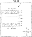
- Fig. 12 is a view illustrating an example of a case where the forgery prevention medium 1 is set as a card 1C.
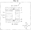
- Fig. 13 is a view illustrating an example of a case where the forgery prevention medium 1 is set as a data page 1D.
- Respective drawings of Figs. 11 to 13 are enlarged views of the vicinity of the light-emitting region 3, 4 in a cross-sectional view that passes through the center of the light-emitting element 311, 411 of the forgery prevention medium 1 illustrated in Fig. 2(A) and is parallel to the XZ plane.
- the transparent protective layer (61, 62) is formed by applying a transparent material (ink) to cover the printed layer (51, 52) and the light-emitting region (3, 4) formed in the window portion (513, 523) provided in the printed layer. According to this, in the window portion (513, 523), a portion other than the light-emitting element (31, 41) of the light-emitting region (3, 4) is filled with the transparent material that forms the transparent protective layer (61, 62).
- the light-emitting element (31, 41) on an inner side of the window portion (512, 513) is in a state of being covered with the transparent protective layer (61, 62) without a gap.
- the forgery prevention medium 1 is set as the plastic paper money 1B
- a polypropylene resin can be used in the substrate layer 2
- an acrylic resin can be used in the transparent protective layer (61, 62), but there is no limitation thereto.
- the transparent protective layer (61, 62) constituted by a transparent film material is disposed to cover the printed layer (51, 52) and the light-emitting region (3, 4) formed in the window portion (513, 523) provided in the printed layer.
- the transparent film material is joined to the substrate layer 2 side through thermal compression, in the window portion (513, 523) provided in the printed layer (51, 52), a portion other than the light-emitting element (31, 41) of the light-emitting region (3, 4) is also filled with a melted transparent film material.
- the light-emitting element (31, 41) is in a state of being covered with the transparent protective layer (61, 62) without a gap.
- the forgery prevention medium 1 is set as the card 1C such as the membership card
- a polyethylene terephthalate resin can be used in the substrate layer 2 (substrate 2A)
- a polyethylene terephthalate resin can be used in the transparent protective layer (61, 62)
- the substrate layer 2 that constitutes the card 1C is not limited to one sheet of substrate, and a mode in which a plurality of substrates 2A (three sheets of substrates 2A in Fig.
- the light-emitting elements (31, 41) may be disposed between the substrates 2A which are laminated.
- the light-emitting element 31 may be disposed between the substrate 2A in a first layer and the substrate 2A in a second layer
- the light-emitting element 41 may be disposed between the substrate 2A in the second layer and the substrate 2A in a third layer. According to this, it is possible to further improve forgery prevention performance of the card 1C (forgery prevention medium 1).
- the plurality of substrates 2A are joined to each other through thermal compression, and the light-emitting element (31, 41) disposed between the substrates 2A is covered with the substrates 2A without a gap.
- the data page 1D has a mode in which the printed layer (51, 52) and the transparent protective layer (61, 62) are sequentially laminated on both surfaces of an opaque (for example, white or the like) substrate layer 2'.
- the substrate layer 2 is provided at a position of the data page 1D at which the light-emitting region (3, 4) is provided.
- the transparent substrate layer 2 is disposed at a position of the opaque substrate layer 2' which corresponds to the light-emitting region (3, 4), the window portion (513, 523) is provided at a position of the printed layer (51, 52) which corresponds to the light-emitting region (3, 4), and the substrate layer 2 is also disposed in the window portion.
- the light-emitting elements (31, 41) of the light-emitting regions (3, 4) are respectively provided on both surfaces (a surface on the Z1 side and a surface on the Z2 side) of the transparent substrate layer 2, and the transparent protective layer (61, 62) is provided to cover the opaque substrate layer 2', the transparent substrate layer 2, and the light-emitting element (31, 41).
- the transparent protective layer (61, 62) is constituted by a transparent film material and is joined to the substrate layer side through thermal compression, and thus it enters a state in which the transparent protective layer (61, 62) covers the light-emitting element (31, 41) without a gap.
- the forgery prevention medium 1 is set as the data page 1D such as the passport
- a polycarbonate resin can be used in the substrate layer 2' (substrate 2'A)
- a polyethylene terephthalate resin can be used in the substrate layer 2
- a polycarbonate resin can be used in the transparent protective layer (61, 62)
- the opaque substrate layer 2' that constitutes the data page 1D is not limited to one sheet of substrate, and a mode in which a plurality of substrates 2'A (three sheets of substrates 2'A in Fig. 13 ) are laminated in correspondence with strength required for the data page 1D or the like may be employed.
- the substrate layer 2 of the data page 1D is not limited to one sheet of substrate, and a mode in which a plurality of substrates 2A (for example, three sheets of substrates 2A) are laminated in correspondence with strength required for the data page 1D or the like may be employed as in the substrate layer 2'.
- the light-emitting element (31, 41) may be disposed between the substrates 2A which are laminated.
- the light-emitting element 31 may be disposed between the substrate 2A in a first layer and the substrate 2A in a second layer
- the light-emitting element 41 may be disposed between the substrate 2A in the second layer and the substrate 2A in a third layer.
- the plurality of substrates 2A are joined to each other through thermal compression, and the light-emitting element (31, 41) disposed between the substrates 2A is covered with the substrates 2A without a gap.
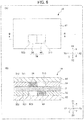
- Fig. 6 is a view illustrating a forgery prevention medium 1A of the second embodiment as the light-emitting medium of the invention
- (A) is a plan view
- (B) is a cross-sectional view taken along line B-B in (A).
- Fig. 7 is a view illustrating a first printed layer 51 including a first light-emitting region 3A in the forgery prevention medium 1A of the second embodiment by virtually extracting the first printed layer 51, and in Fig.
- FIG. 7 (A) is a plan view, and (B) is a rear view.
- Fig. 8 is a view illustrating a second printed layer 52 including a second light-emitting region 4A in the forgery prevention medium 1A of the second embodiment by virtually extracting the second printed layer 52, and in Fig. 8 , (A) is a plan view, and (B) is a rear view.
- Fig. 9 is a view illustrating a light-emitting form when the forgery prevention medium 1A of the second embodiment is irradiated with non-visible light in the first wavelength region, and in Fig. 9 , (A) is a plan view, and (B) is a rear view.
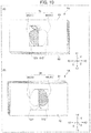
- FIG. 10 is a view illustrating a light-emitting form when the forgery prevention medium 1A of the second embodiment is irradiated with non-visible light in the second wavelength region, and in Fig. 10 , (A) is a plan view, and (B) is a rear view.
- the first light-emitting region 3 and the second light-emitting region 4 have shapes which partially do not overlap each other (shapes which partially overlap each other) when viewed in the thickness direction Z of the substrate 2 through the substrate 2.
- the first light-emitting region 3A and the second light-emitting region 4A have shapes which completely do not overlap each other when viewed in the thickness direction Z of the substrate 2 through the substrate 2.
- the first light-emitting region 3A and the second light-emitting region 4A show an incomplete shape only on one side.
- the first light-emitting region 3A and the second light-emitting region 4A show a complete shape on both sides.
- the second embodiment is an embodiment in which the completeness/incompleteness of light-emission shape is clear, but it can be understood that the first embodiment also has completeness/incompleteness of the light-emission shape.
- the window portion may be filled with a transparent material of a polycarbonate resin or the like, or a transparent member of the same resin or the like may be disposed in the window portion in accordance with an application mode. That is, the periphery of light-emitting elements (31, 41) provided in a window portion (513, 523) is covered with the transparent material or the like (transparent protective layer) without a gap.
- the first light-emitting region 3A and the second light-emitting region 4A have shapes which completely do not overlap each other when viewed in the thickness direction Z of the substrate layer 2 through the substrate layer 2.
- a first light-emitting element 31 of the first light-emitting region 3A has a shape of the left half of an apple being fruit.
- a second light-emitting element 41 of the second light-emitting region 4A has a shape of the right half of the apple.
- the first light-emitting element 31 having the shape of the left half of the apple, and the second light-emitting element 41 having the shape of the right half of the apple are adjacent to each other.
- an opposing edge in the first light-emitting element 31 and an opposing edge in the second light-emitting element 41 may match each other, may be slightly spaced away from each other, or may slightly overlap each other.
- the opposing edge in the first light-emitting element 31 and the opposing edge in the second light-emitting element 41 may be greatly spaced away from each other without being adjacent to each other.
- the fluorescent substance of the first light-emitting region 3A and the fluorescent substance of the second light-emitting region 4A emit light of a color visually recognized as the same color when being irradiated with non-visible light in the first wavelength region, and emit light of color visually recognized as the same color when being irradiated with non-visible light in the second wavelength region.
- the fluorescent substance of the first light-emitting region 3A and the fluorescent substance of the second light-emitting region 4A may emit light of colors visually recognized as different colors when being irradiated with non-visible light in the first wavelength region, and may emit light of colors visually recognized as different colors even when being irradiated with non-visible light in the second wavelength region.
- Non-visible light in the first wavelength region is transmitted through the transparent protective layer and the window portion, and is transmitted through the substrate layer 2. Accordingly, when being irradiated with non-visible light in the first wavelength region, a light-emitting region located on an irradiation source side emits light, and a light-emitting region located on a side opposite to the irradiation source with the substrate layer 2 interposed therebetween also emits light. That is, as illustrated in Fig.
- both the first light-emitting region 3A and the second light-emitting region 4A emit light.
- the first light-emitting region 3A and the second light-emitting region 4A do not exist in an outermost layer, but are indicated by a solid line for convenience.
- a complete light-emission shape 34 showing the apple having a complete shape is formed (emits light and is visually recognized).
- the first light-emitting region 3A when being irradiated with non-visible light in the second wavelength region from the first light-emitting region 3A (first transparent protective layer 61) side, the first light-emitting region 3A emits light, but the second light-emitting region 4A located on an opposite side with the substrate layer 2 interposed therebetween does not emit light.
- the first light-emitting region 3A does not exist in an outermost layer, but is indicated by a solid line for convenience, and light-emission is indicated by dot hatching.
- the second light-emitting region 4A when being irradiated with non-visible light from the second light-emitting region 4A (second transparent protective layer 62) side, the second light-emitting region 4A emits light, but the first light-emitting region 3A located on an opposite side with the substrate layer 2 interposed therebetween does not emit light.
- the second light-emitting region 4A does not exist in an outermost layer, but is indicated by a solid line for convenience, and light-emission is indicated by dot hatching.
- the first light-emitting region 3A and the second light-emitting region 4A show an incomplete shape only on one side (refer to Fig. 10 ).
- the first light-emitting region 3A and the second light-emitting region 4A show a complete shape on both sides (refer to Fig. 9 ).
- the first light-emitting region 3 and the second light-emitting region 4 respectively constitute a part of the first printed layer 51 and the second printed layer 52, but there is no limitation thereto.
- the first light-emitting region 3 and the second light-emitting region 4 may be provided in a whole surface in the XY plane.
- a layer formed through (application and the like) other than printing may be employed instead of the first printed layer 51 and the second printed layer 52.
- the light-emitting medium of the invention may be provided with a layer that is not provided in the above-described embodiments, and may not be provided with a layer that is provided in the embodiments but is not essential in an opposite manner.
- the light-emitting medium of the invention is applicable to various media which use a variation, unexpectedness, or the like in the light-emission form without limitation to the forgery prevention medium.
- the shape of the light-emitting medium may be a plate shape or a block shape without limitation to the sheet shape. Discrimination of the sheet shape, the plate shape, and the block shape is made on relative and technical basis on the basis of a ratio of thickness or the like.
Landscapes
- General Health & Medical Sciences (AREA)
- Health & Medical Sciences (AREA)
- Engineering & Computer Science (AREA)
- Toxicology (AREA)
- Physics & Mathematics (AREA)
- Textile Engineering (AREA)
- Vascular Medicine (AREA)
- Spectroscopy & Molecular Physics (AREA)
- General Physics & Mathematics (AREA)
- Manufacturing & Machinery (AREA)
- Credit Cards Or The Like (AREA)
- Printing Methods (AREA)
- Inspection Of Paper Currency And Valuable Securities (AREA)
Abstract
Description
- The present invention relates to a light-emitting medium including a substrate and a light-emitting region, a forgery prevention medium, and a method for determining authenticity of the light-emitting medium.
- In media including securities such as an exchange ticket for money and a prepaid card, and identification cards such as a license which are necessary to prevent forgery, recently, micro characters, a copy prevention pattern, an infrared absorption ink, a fluorescent ink, or the like has been used to enhance security properties. Among these, the fluorescent ink is an ink containing a fluorescent substance that is not substantially visually recognized under visible light, and is visually recognized when being irradiated with non-visible light (ultraviolet rays or infrared rays). When using such fluorescent ink, it is possible to form a fluorescent image (light-emitting image), which appears only when the securities and the like are irradiated with non-visible light in a specific wavelength region, in the securities and the like. According to this, it is possible to prevent the securities from being easily forged with a general-purpose color printer or the like.
- Recently, articles including a forgery prevention countermeasure as described above mainly include various transparent media containing a polymer compound such as plastic. For example, instead of paper, transparent plastic currency, a transparent card, and the like can be exemplified. For example, a plastic substrate that emits visually transparent fluorescence by adjusting a refractive index is disclosed (Patent Document 1).
- In addition, to further enhance a forgery prevention effect, there is suggested a configuration in which a light-emitting image that is not visually recognized in accordance with naked eyes is formed in the securities by using a fluorescent ink. For example,
Patent Document 2 discloses a medium including a light-emitting image that is formed by using a first fluorescent ink and a second fluorescent ink. In this case, the first fluorescent ink and the second fluorescent ink are inks which are visually recognized as the same color under visible light and ultraviolet ray when being viewed with naked eyes, and are visually recognized as different colors when being viewed through a discrimination tool. According to this, it is difficult for the light-emitting image formed on the securities to be easily forged, and as a result, the forgery prevention effect due to the fluorescent inks is enhanced. - However, it is preferable to simply and rapidly carry out a procedure of discriminating whether or not the securities are forged. Accordingly, there is a demand for a medium with which discrimination as to whether or not the securities are forged can be easily and rapidly made by using normal blacklight without using an additional discrimination tool.
-
- Patent Document 1: Japanese Patent No.
5681725 - Patent Document 2: Japanese Patent No.
4418881 - However, according to the technology disclosed in
Patent Document 2, it is necessary to prepare two kinds of tools including blacklight and a discrimination tool. Therefore, there is a demand for a medium capable of more easily realizing different light-emitting forms capable of being easily discriminated by using normal black light. In addition, the medium may also be used for purposes other than forgery prevention (authenticity determination). - An object of the invention is to provide a light-emitting medium capable of realizing different light-emitting forms capable of being easily discriminated by using normal blacklight, a forgery prevention medium, and a method for determining authenticity of the light-emitting medium.
- The invention accomplishes the object by the following means for solving the problems. Note that, description will be made by applying reference numerals corresponding to an embodiment of the invention for easy understanding, but there is no limitation thereto.
- According to a first aspect of the invention, there is provided a light-emitting medium (1, 1A) including a substrate (2), and a first light-emitting region (3) and a second light-emitting region (4) disposed on both sides of the substrate (2). The substrate (2) includes a selective transmission layer through which non-visible light in a first wavelength region is transmitted, and non-visible light in a second wavelength region different from the first wavelength region is not substantially transmitted, and the first light-emitting region (3) and the second light-emitting region (4) contain a fluorescent substance that emits light when being irradiated with non-visible light in the first wavelength region and also emits light when being irradiated with non-visible light in the second wavelength region.
- According to a second aspect of the invention, in the light-emitting medium according to the first aspect, the first light-emitting region (3) and the second light-emitting region (4) have shapes which at least partially do not overlap each other when viewed in a thickness direction (Z) of the substrate (2) through the substrate (2).
- According to a third aspect of the invention, in the light-emitting medium according to the first or second aspect, the fluorescent substance of the first light-emitting region (3) and the fluorescent substance of the second light-emitting region (4) emit light which are visually recognized as different colors when being irradiated with non-visible light in the first wavelength region, and emit light which are visually recognized as different colors even when being irradiated with non-visible light in the second wavelength region.
- According to a fourth aspect of the invention, in the light-emitting medium according to any one of the first to third aspects, the first light-emitting region (3A) and the second light-emitting region (4A) show an incomplete shape only on one side, and in a state in which both the fluorescent substance of the first light-emitting region (3A) and the fluorescent substance of the second light-emitting region (4A) emit light, the first light-emitting region (3A) and the second light-emitting region (4A) show a complete shape on both sides.
- According to a fifth aspect of the invention, there is provided a forgery prevention medium to which the light-emitting medium according to any one of the first to fourth aspects is applied.
- According to a sixth aspect of the invention, there is provided a method for determining authenticity of the light-emitting medium according to any one of the first to fourth aspects. The method includes: a preparation process of preparing a light-emitting medium (1, 1A); a first wavelength irradiation process of irradiating the light-emitting medium (1, 1A) with non-visible light in a first wavelength region to confirm light-emission of both of the fluorescent substance of the first light-emitting region (3) and the fluorescent substance of the second light-emitting region (4); a second wavelength irradiation process of irradiating the light-emitting medium (1, 1A) with non-visible light in a second wavelength region to confirm light-emission of only one on an irradiation source side between the fluorescent substance of the first light-emitting region (3) and the fluorescent substance of the second light-emitting region (4); and a determination process of determining that the light-emitting medium (1, 1A) is genuine when confirmation is obtained in both the first wavelength irradiation process and the second wavelength irradiation process.
- According to the invention, it is possible to provide a light-emitting medium capable of realizing different light-emitting forms capable of being easily discriminated by using normal blacklight, a forgery prevention medium, and a method for confirming the light-emitting medium.
-
-
Fig. 1 is a view illustrating aforgery prevention medium 1 of a first embodiment as a light-emitting medium of the invention, and inFig. 1 , (A) is a plan view, and (B) is a cross-sectional view taken along line B-B in (A). -
Fig. 2 is a view illustrating a first printedlayer 51 including a first light-emittingregion 3 in theforgery prevention medium 1 of the first embodiment by virtually extracting the first printedlayer 51, and inFig. 2 , (A) is a plan view, and (B) is a rear view. -
Fig. 3 is a view illustrating a second printedlayer 52 including a second light-emittingregion 4 in theforgery prevention medium 1 of the first embodiment by virtually extracting the second printedlayer 52, and inFig. 3 , (A) is a plan view, and (B) is a rear view. -
Fig. 4 is a view illustrating a light-emitting form when theforgery prevention medium 1 of the first embodiment is irradiated with non-visible light in a first wavelength region, and inFig. 4 , (A) is a plan view, and (B) is a rear view. -
Fig. 5 is a view illustrating a light-emitting form when theforgery prevention medium 1 of the first embodiment is irradiated with non-visible light in a second wavelength region, and inFig. 5 , (A) is a plan view, and (B) is a rear view. -
Fig. 6 is a view illustrating aforgery prevention medium 1A of a second embodiment as the light-emitting medium of the invention, and inFig. 6 , (A) is a plan view, and (B) is a cross-sectional view taken along line B-B in (A). -
Fig. 7 is a view illustrating a first printedlayer 51 including a first light-emittingregion 3A in theforgery prevention medium 1A of the second embodiment by virtually extracting the first printedlayer 51, and inFig. 7 , (A) is a plan view, and (B) is a rear view. -
Fig. 8 is a view illustrating a second printedlayer 52 including a second light-emittingregion 4A in theforgery prevention medium 1A of the second embodiment by virtually extracting the second printedlayer 52, and inFig. 8 , (A) is a plan view, and (B) is a rear view. -
Fig. 9 is a view illustrating a light-emitting form when theforgery prevention medium 1 of the first embodiment is irradiated with non-visible light in the first wavelength region, and inFig. 9 , (A) is a plan view, and (B) is a rear view. -
Fig. 10 is a view illustrating a light-emitting form when theforgery prevention medium 1 of the first embodiment is irradiated with non-visible light in the second wavelength region, and inFig. 10 , (A) is a plan view, and (B) is a rear view. -
Fig. 11 is a view illustrating an example of a case where theforgery prevention medium 1 is set asplastic paper money 1B.Fig. 12 is a view illustrating an example of a case where theforgery prevention medium 1 is set as acard 1C. -
Fig. 13 is a view illustrating an example of a case where theforgery prevention medium 1 is set asdata page 1D. - Hereinafter, embodiments of the invention will be described with the drawings and the like. The embodiments relate to a case where a light-emitting medium of the invention is applied to a forgery prevention medium. Here, examples of the forgery prevention medium include a cash card that is used in a bank or the like, a membership card that is used in a shop or the like, plastic paper money (resin sheet paper money), a data page of passport, and the like. Note that, for example, when being used as a cash card or a membership card, the forgery prevention medium may be provided with an IC chip or a communication antenna that is used in individual authentication or the like, or may be provided with a printed layer that applies a pattern or the like to front and rear surfaces of the card, functional layers, and the like in addition to the configuration illustrated in
Fig. 1 to be described later. In addition, even in the case of being used as paper money, the forgery prevention medium may be further provided with a forgery prevention configuration such as a water mark provided in typical paper money or the like. -
Fig. 1 is a view illustrating aforgery prevention medium 1 of a first embodiment as a light-emitting medium of the invention, and inFig. 1 , (A) is a plan view and (B) is a cross-sectional view taken along line B-B in (A).Fig. 2 is a view illustrating a first printedlayer 51 including a first light-emittingregion 3 in theforgery prevention medium 1 of the first embodiment by virtually extracting the first printedlayer 51, and inFig. 2 , (A) is a plan view, and (B) is a rear view.Fig. 3 is a view illustrating a second printedlayer 52 including a second light-emittingregion 4 in theforgery prevention medium 1 of the first embodiment by virtually extracting the second printedlayer 52, and inFig. 3 , (A) is a plan view, and (B) is a rear view.Fig. 4 is a view illustrating a light-emitting form when theforgery prevention medium 1 of the first embodiment is irradiated with non-visible light in a first wavelength region, and inFig. 4 , (A) is a plan view, and (B) is a rear view.Fig. 5 is a view illustrating a light-emitting form when theforgery prevention medium 1 of the first embodiment is irradiated with non-visible light in a second wavelength region, and inFig. 5 , (A) is a plan view, and (B) is a rear view. - In the embodiment and the drawings, an XYZ orthogonal coordinate system is provided for easy explanation and easy understanding. The coordinate system shows a right and left direction X (a left side: X1, and a right side: X2), a vertical direction Y (an upper side: Y1, and a lower side: Y2), and a thickness direction Z (a front (upper) side: Z1, and a rear (lower) side: Z2) on the basis of a state of
Fig. 1 . A shape is appropriately simplified or deformed in accordance with the drawings. For example, inFig. 1 , shapes of the first light-emittingregion 3 and the second light-emittingregion 4 are simplified, and the first light-emittingregion 3 and the second light-emittingregion 4 are illustrated in a rectangular shape. InFigs. 2 to 5 , sizes of the first light-emittingregion 3 and the second light-emittingregion 4 are deformed, and the shapes of the first light-emittingregion 3 and the second light-emittingregion 4 are enlarged. - As illustrated in
Figs. 1 to 3 , theforgery prevention medium 1 is a sheet-shaped article having a rectangular shape in an XY plane, and is a laminated body in which a first transparentprotective layer 61, the first printedlayer 51 including the first light-emittingregion 3, asubstrate layer 2, the second printedlayer 52 including the second light-emittingregion 4, and a second transparentprotective layer 62 are laminated in this order from the front side Z1 to the rear side Z2 in the thickness direction Z. Note that, when making a common description, the "first transparentprotective layer 61" and the "second transparentprotective layer 62" may be simply referred to as "transparent protective layer". Similarly, when making a common description, the "first light-emittingregion 3" and the "second light-emittingregion 4" may be simply referred to as "light-emitting region". When making a common description, the "first printedlayer 51" and the "second printedlayer 52" may be referred to as "printed layer". - The
substrate layer 2 is a layer that becomes a substrate of theforgery prevention medium 1, and may be referred to as "substrate 2" in this specification. For example, as thesubstrate layer 2, transparent polypropylene (PP), polyethylene terephthalate (PET), polycarbonate (PC), or the like with excellent printability and processability is used. Here, "transparent" represents that visible light is transmitted. A selective transmission property of thesubstrate layer 2 as one characteristic of the invention will be described later in detail. Note that, typically, thesubstrate layer 2 is a layer having the highest rigidity, but a layer having further higher rigidity or a layer having a larger thickness may exist in the forgery prevention medium (light-emitting medium) 1 in addition to thesubstrate layer 2. - The first printed
layer 51 is formed on an upper surface of thesubstrate layer 2 through printing. Alower surface 512 of the first printedlayer 51 is in contact with the upper surface of thesubstrate layer 2. The second printedlayer 52 is formed on a lower surface of thesubstrate layer 2 through printing. Anupper surface 521 of the second printedlayer 52 is in contact with the lower surface of thesubstrate layer 2. Examples of the printing include silk screen printing, offset, gravure printing, and the like. It is preferable that an ink of the first printed layer 51 (excluding the first light-emitting region 3) and the second printed layer 52 (excluding the second light-emitting region 4) has a high light-shielding property of not allowing light to be transmitted therethrough (for example, an ink having a high shielding property at a white color). - As illustrated in
Fig. 2 , a partial region of an XY plane in the first printedlayer 51 is set to afirst window portion 513 that passes through the first printedlayer 51 in a thickness direction Z. As illustrated inFig. 3 , a partial region of an XY plane in the second printedlayer 52 is set to asecond window portion 523 that passes through the second printedlayer 52 in the thickness direction Z. In a case where an attention is paid only to the first printedlayer 51, when the first printedlayer 51 is seen from the thickness direction Z, the region of thefirst window portion 513 is observed transparently. This is also true of the second printedlayer 52. When making a common description, the "first window portion 513" and the "second window portion 523" may be referred to as "window portion". In addition, when viewed in the thickness direction Z, an external shape of thefirst window portion 513 and an external shape of thesecond window portion 523 equal and match each other. Note that, an external shape of one side of thefirst window portion 513 and thesecond window portion 523 may be set to be larger than an external shape of the other side without limitation to the above-described mode. Note that, since the window portion provided in each of the printed layers is a region in which printing is not performed to a part of the printed layer, that is, a region through which incident light can be transmitted, in accordance with an application mode of theforgery prevention medium 1, the window portion may be filled with a transparent material of a polycarbonate resin or the like, or a transparent member of the same resin or the like (polycarbonate resin or the like) may be disposed in the window portion (an application mode of theforgery prevention medium 1 will be described later). - The first light-emitting
region 3 is provided in thefirst window portion 513. The second light-emittingregion 4 is provided in thesecond window portion 523. The first light-emittingregion 3 and the second light-emittingregion 4 are formed by printing (for example, offset) or applying an ink containing a fluorescent substance to at least a part of a position corresponding to the window portion of thesubstrate layer 2. The first light-emittingregion 3 and the second light-emittingregion 4 have transparency when light is not emitted. In addition, the first light-emittingregion 3 and the second light-emittingregion 4 contain a fluorescent substance that emits visible light when being irradiated with non-visible light in a first wavelength region, and emits visible light even when being irradiated with non-visible light in a second wavelength region. Details of the fluorescent substance contained in the light-emitting region will be described later. Note that, the first light-emittingregion 3 and the second light-emittingregion 4 may be formed after printing the first printedlayer 51 and the second printedlayer 52 on thesubstrate layer 2, or after forming the first light-emittingregion 3 and the second light-emittingregion 4 on thesubstrate layer 2, the first printedlayer 51 and the second printedlayer 52 may be subsequently printed. - The transparent protective layer is a layer called an overcoat layer, and is a transparent layer through which various kinds of light are transmitted. A known transparent material can be used as the transparent protective layer, and the transparent protective layer is formed, for example, by a polycarbonate resin, an acrylic resin, a polyethylene terephthalate resin, or the like. The first transparent
protective layer 61 is a layer that is provided on anupper surface 511 of the first printedlayer 51 to protect the first printedlayer 51. The second transparentprotective layer 62 is a layer that is provided on alower surface 522 of the second printedlayer 52 to protect the second printedlayer 52. - The fluorescent substance contained in the light-emitting region is not particularly limited as long as the fluorescent substance absorbs an electromagnetic wave having a specific wavelength in a wavelength region of an ultraviolet ray region or an infrared ray region and emits light. Examples of the fluorescent substance include an ultraviolet ray absorbing fluorescent substance and an infrared ray absorbing fluorescent substance. An ultraviolet ray represents an electromagnetic wave having a wavelength of less than 400 nm. In addition, the ultraviolet ray region represents a wavelength region of less than 400 nm. Visible light represents an electromagnetic wave (light) having a wavelength in a wavelength range of 400 nm to 700 nm. In addition, a visible light region represents a wavelength region of 400 nm to 700 nm. An infrared ray represents an electromagnetic wave having a wavelength of greater than 700 nm. In addition, the infrared ray region represents a wavelength region of greater than 700 nm.
- The ultraviolet ray absorbing fluorescent substance is a fluorescent substance that absorbs an ultraviolet ray, and in the invention, a fluorescent substance that absorbs an ultraviolet ray and emits visible light is used. Examples of the ultraviolet ray absorbing fluorescent substance that absorbs an ultraviolet ray and emits visible light include a fluorescent substance that absorbs UV-A (in a wavelength range of 315 nm to 380 nm) and emits visible light, a fluorescent substance that absorbs UV-B (in a wavelength range of 280 nm to 315 nm) and emits visible light, a fluorescent substance that absorbs UV-C (in a wavelength range of 200 nm to 280 nm) and emits visible light, and the like. Note that, visible light that is emitted from the fluorescent substance can be appropriately selected in correspondence with the kind of the fluorescent substance.
- As the ultraviolet ray absorbing fluorescent substance, a known fluorescent substance can be exemplified, and specific examples thereof include an ultraviolet-excited and visible light emitting type fluorescent substance described in Japanese Unexamined Patent Application Publication No.
2012-011550 5573469 - The infrared ray absorbing fluorescent substance is a fluorescent substance that absorbs an infrared ray, and in the invention, a fluorescent substance that absorbs an infrared ray and emits visible light is used. Examples of the infrared ray absorbing fluorescent substance that absorbs an infrared ray and emits visible light include a fluorescent substance that is called an up-conversion material, absorbs a near infrared light of 800 nm, and emits green visible light near 530 nm, and the like. An excitation wavelength is appropriately selected in accordance with a fluorescent substance, and can be appropriately selected in correspondence with a kind of the fluorescent substance with respect to visible light that is emitted from the fluorescent substance.
- As the infrared ray absorbing fluorescent substance, a known fluorescent substance can be exemplified, and specific examples thereof include an infrared-excited and visible light emitting type fluorescent substance described in Japanese Unexamined Patent Application Publication No.
2012-011550 4276864 4498825 - In the invention, a plurality of kinds of fluorescent substances may be used. In addition, in the case or the like of forming the light-emitting regions in a pattern shape, the kinds of fluorescent substances contained in patterns of each of the light-emitting regions may be made different.
- The
substrate layer 2 is constituted by a selective transmission layer through which non-visible light in a first wavelength region is transmitted and non-visible light in a second wavelength region different from the first wavelength region is not substantially transmitted. For example, non-visible light in the first wavelength region is an ultraviolet ray (non-visible light) so-called UV-A in a wavelength region less than 315 to 400 nm. Non-visible light in the second wavelength region is an ultraviolet ray (non-visible light) so-called UV-C in a wavelength region of 200 to 280 nm. Note that, "substantially not transmitted" represents that light is not transmitted to a certain extent capable of obtaining the effect of the invention, and light may be transmitted to a certain extent in a range not deteriorating the effect of the invention in the opposite viewpoint. As a form of "not transmitted", "absorbs" and/or "reflects" are exemplified. - The first light-emitting
region 3 and the second light-emittingregion 4 have shapes which at least partially do not overlap each other when viewed through thesubstrate layer 2 in the thickness direction Z of thesubstrate layer 2. Specifically, as illustrated inFig. 2 , the first light-emittingregion 3 includes three rectangular first light-emittingelements 31 which are linearly arranged. As illustrated inFig. 3 , the second light-emittingregion 4 includes three triangular second light-emittingelements 41 which are linearly arranged. When viewed through thesubstrate layer 2 in the thickness direction Z of thesubstrate layer 2, as illustrated inFig. 4 , a central first light-emittingelement 311 located at the center among the three first light-emittingelements 31, and a central second light-emittingelement 411 located at the center among the three second light-emittingelements 41 partially overlap each other. On the other hand, non-central first light-emittingelements 312 located at a position other than the center among the three first light-emittingelements 31 and non-central second light-emittingelements 412 located at a position other than the center among the three second light-emittingelements 41 do not overlap each other. The linear arrangement shape of the first light-emittingelements 31 and the linear arrangement shape of the second light-emittingelements 41 intersect each other in an X-shape. In addition, in another viewpoint, the first light-emittingelements 31 and the second light-emittingelements 41 are arranged similarly to "5" of dice and emit light. - Description will be given of different-color light-emission as a first coloring form. The fluorescent substance of the first light-emitting
region 3 and the fluorescent substance of the second light-emittingregion 4 emit light of colors visually recognized as different colors when being irradiated with non-visible light in the first wavelength region, and emit light of colors visually recognized as different colors even when being irradiated with non-visible light in the second wavelength region. For example, when being irradiated with non-visible light in the first wavelength region or when being irradiated with non-visible light in the second wavelength region, the fluorescent substance of the first light-emittingregion 3 emits green light, and the fluorescent substance of the second light-emittingregion 4 emits red light. - In a range in which the first light-emitting
region 3 and the second light-emittingregion 4 overlap each other, light of a color visually recognized as a further different color is emitted. For example, in the case of being irradiated with non-visible light in the first wavelength region, in a range in which the central first light-emittingelement 311 and the central second light-emittingelement 411 overlap each other, yellow light that is shown by additive color mixture of green light and red light is emitted. - Description will be given of same-color light-emission as a second coloring form. The fluorescent substance of the first light-emitting
region 3 and the fluorescent substance of the second light-emittingregion 4 emit light of a color visually recognized as the same color when being irradiated with non-visible light in the first wavelength region, and emit light of color visually recognized as the same color when being irradiated with non-visible light in the second wavelength region. Here, the color in irradiation with non-visible light in the first wavelength region and the color in irradiation with non-visible light in the second wavelength region may be different from each other or may not be different from each other. In a case where the colors are not different from each other (in the case of the same color), only a light-emission shape is changed. - For example, when being irradiated with non-visible light in the first wavelength region, the fluorescent substance of the first light-emitting
region 3 and the fluorescent substance of the second light-emittingregion 4 emit green light as the same color. When being irradiated with non-visible light in the second wavelength region, the fluorescent substance of the first light-emittingregion 3 and the fluorescent substance of the second light-emittingregion 4 emit red light as the same color. Here, the color (green) in irradiation with non-visible light in the first wavelength region, and the color (red) in irradiation with non-visible light in the second wavelength region may be different from each other, or may not be different from each other. In a case where colors are not different from each other (in the case of the same color), only a light-emission shape is changed. - In the invention, the "same color" represents that chromaticities of the two colors are close to each other to a certain extent in which a color difference is not discriminated with naked eyes. More specifically, the "same color" represents that a color difference ΔE*ab between the two colors is 10 or less, and preferably 3 or less. In addition, the "different color" represents that a color difference ΔE*ab between the two colors is 10 or greater. Here, the color difference ΔE*ab is a value that is calculated on the basis of L*, a*, and b* in an L*a*b* color system, and is a value that becomes an index relating to a difference of colors in the case of being observed with naked eyes. Note that, L*, a*, and b* in the L*a*b* color system or tristimulus values X, Y, and Z in an XYZ color system are calculated on the basis of a spectrum of light, or the like. In addition, a relationship according to a known conversion expression is established between the L*, a*, and b*, and the tristimulus values X, Y, and Z. The above-described tristimulus values and the color difference ΔE*ab are calculated by a method described, for example, in Japanese Patent No.
5573469 - Description will be given of a light-emitting form in irradiation with non-visible light in the first wavelength region. At the time of irradiation with non-visible light in the first wavelength region, non-visible light in the first wavelength region is transmitted through the transparent protective layer and the window portion, and is transmitted through the
substrate layer 2. Accordingly, when being irradiated with non-visible light in the first wavelength region, a light-emitting region located on an irradiation source side emits light, and a light-emitting region located on a side opposite to the irradiation source with thesubstrate layer 2 interposed therebetween also emits light. That is, as illustrated inFig. 4 , both the first light-emittingregion 3 and the second light-emittingregion 4 emit light. Note that, inFig. 4 , the first light-emittingregion 3 and the second light-emittingregion 4 do not exist in an outermost layer, but are indicated by a solid line for convenience. In a range in which the central first light-emittingelement 311 and the central second light-emittingelement 411 overlap each other, yellow light is emitted. In only the first light-emittingelements 31, green light is emitted. In only the second light-emittingelements 41, red light is emitted. As described above, a total of six first light-emittingelements 31 and second light-emittingelements 41 emit light. Note that, the central first light-emittingelement 311 and the central second light-emittingelement 411 among six elements integrally emit light in a state of partially overlapping each other. - Description will be given of a light-emitting form in irradiation with non-visible light in the second wavelength region. At the time of irradiation with non-visible light in the second wavelength region, non-visible light in the second wavelength region is transmitted through the transparent protective layer and the window portion, but is not transmitted through the
substrate layer 2. Accordingly, when being irradiated with non-visible light in the second wavelength region, a light-emitting region located on an irradiation source side emits light, but a light-emitting region located on a side opposite to the irradiation source with thesubstrate layer 2 interposed therebetween does not emit light. That is, as illustrated inFig. 5(A) , when being irradiated with non-visible light in the second wavelength region from the first light-emitting region 3 (first transparent protective layer 61) side, the first light-emittingregion 3 emits light, but the second light-emittingregion 4 located on an opposite side with thesubstrate layer 2 interposed therebetween does not emit light. Note that, inFig. 5(A) , the first light-emittingregion 3 does not exist in an outermost layer, but is indicated by a solid line for convenience, and light-emission is indicated by dot hatching. - Similarly, as illustrated in
Fig. 5(B) , when being irradiated with non-visible light in the second wavelength region from the second light-emitting region 4 (second transparent protective layer 62) side, the second light-emittingregion 4 emits light, but the first light-emittingregion 3 located on an opposite side with thesubstrate layer 2 interposed therebetween does not emit light. Note that, inFig. 5(B) , the second light-emittingregion 4 does not exist in an outermost layer, but is indicated by a solid line for convenience, and light-emission is indicated by dot hatching. - Next, description will be given of a method for determining authenticity of the
forgery prevention medium 1 of the first embodiment as an example of a method for determining authenticity of the invention. First, in a preparation process, theforgery prevention medium 1 is prepared. Next, in a first wavelength irradiation process, theforgery prevention medium 1 is irradiated with non-visible light in the first wavelength region, and confirms that both the fluorescent substance of the first light-emittingregion 3 and the fluorescent substance of the second light-emittingregion 4 emit light. Next, in a second wavelength irradiation process, theforgery prevention medium 1 is irradiated with non-visible light in the second wavelength region, and confirms that only one on an irradiation source side between the fluorescent substance of the first light-emittingregion 3 and the fluorescent substance of the second light-emittingregion 4 emits light. In addition, in a determination process, as in a case where confirmation is obtained in both the first wavelength irradiation process and the second wavelength irradiation process, it is determined that theforgery prevention medium 1 is genuine. Note that, the first wavelength irradiation process and the second wavelength irradiation process may be performed in a reverse order. - According to the
forgery prevention medium 1 of the first embodiment, for example, the following effect is obtained. Theforgery prevention medium 1 of the first embodiment includes thesubstrate 2, and the first light-emittingregion 3 and the second light-emittingregion 4 which are respectively disposed on both sides of thesubstrate 2. Thesubstrate 2 is constituted by a selective transmission layer through which non-visible light in the first wavelength region is transmitted, and non-visible light in the second wavelength region different from the first wavelength region is not substantially transmitted. The first light-emittingregion 3 and the second light-emittingregion 4 contain a fluorescent substance that emits light when being irradiated with non-visible light in the first wavelength region, and emits light even when being irradiated with non-visible light in the second wavelength region. - Accordingly, light-emitting forms are different between irradiation with non-visible light in the first wavelength region (refer to
Fig. 4 ) and irradiation with non-visible light in the second wavelength region (refer toFig. 5 ). Accordingly, different light-emitting forms capable of being easily discriminated by using normal blacklight can be realized. Accordingly, for example, it is possible to easily determine authenticity of theforgery prevention medium 1 with naked eyes. - In addition, in the
forgery prevention medium 1 of the first embodiment, the first light-emittingregion 3 and the second light-emittingregion 4 have shapes which at least partially do not overlap each other when viewed in the thickness direction Z of thesubstrate 2 through thesubstrate 2. For example, even in a configuration in which the fluorescent substance of the first light-emittingregion 3 and the fluorescent substance of the second light-emittingregion 4 emit light of a color visually recognized as the same color when being irradiated with non-visible light in the first wavelength region, and emit light of a color visually recognized as the same color even when being irradiated with non-visible light in the second wavelength region, light-emission shapes as light-emitting forms are difference between irradiation with non-visible light in the first wavelength region (refer toFig. 4 ) and irradiation with non-visible light in the second wavelength region (refer toFig. 5 ). Accordingly, it is possible to perform discrimination with naked eyes on the basis of a difference in the light-emission shape. - In addition, in the
forgery prevention medium 1 of the first embodiment, the fluorescent substance of the first light-emittingregion 3 and the fluorescent substance of the second light-emittingregion 4 emit light of colors visually recognized as different colors when being irradiated with non-visible light in the first wavelength region, and emit light of colors visually recognized as different colors even when being irradiated with non-visible light in the second wavelength region. According to this, coloring as a light-emitting form is different between irradiation with non-visible light in the first wavelength region (refer toFig. 4 ) and irradiation with non-visible light in the second wavelength region (refer toFig. 5 ). It is possible to perform discrimination with naked eyes on the basis of the difference in coloring. - Next, an application example of the
forgery prevention medium 1 will be described.Fig. 11 is a view illustrating an example of a case where theforgery prevention medium 1 is set asplastic paper money 1B.Fig. 12 is a view illustrating an example of a case where theforgery prevention medium 1 is set as acard 1C.Fig. 13 is a view illustrating an example of a case where theforgery prevention medium 1 is set as adata page 1D. Respective drawings ofFigs. 11 to 13 are enlarged views of the vicinity of the light-emittingregion element forgery prevention medium 1 illustrated inFig. 2(A) and is parallel to the XZ plane. - In a case where the
forgery prevention medium 1 is set as theplastic paper money 1B, for example, as illustrated inFig. 11 , the transparent protective layer (61, 62) is formed by applying a transparent material (ink) to cover the printed layer (51, 52) and the light-emitting region (3, 4) formed in the window portion (513, 523) provided in the printed layer. According to this, in the window portion (513, 523), a portion other than the light-emitting element (31, 41) of the light-emitting region (3, 4) is filled with the transparent material that forms the transparent protective layer (61, 62).
According to this, the light-emitting element (31, 41) on an inner side of the window portion (512, 513) is in a state of being covered with the transparent protective layer (61, 62) without a gap. In a case where theforgery prevention medium 1 is set as theplastic paper money 1B, for example, a polypropylene resin can be used in thesubstrate layer 2, and an acrylic resin can be used in the transparent protective layer (61, 62), but there is no limitation thereto. - In addition, in a case where the
forgery prevention medium 1 is set as thecard 1C such as a membership card, for example, as illustrated inFig. 12 , the transparent protective layer (61, 62) constituted by a transparent film material is disposed to cover the printed layer (51, 52) and the light-emitting region (3, 4) formed in the window portion (513, 523) provided in the printed layer. In this case, when the transparent film material is joined to thesubstrate layer 2 side through thermal compression, in the window portion (513, 523) provided in the printed layer (51, 52), a portion other than the light-emitting element (31, 41) of the light-emitting region (3, 4) is also filled with a melted transparent film material. According to this, on an inner side of the window portion (513, 523), the light-emitting element (31, 41) is in a state of being covered with the transparent protective layer (61, 62) without a gap. In a case where theforgery prevention medium 1 is set as thecard 1C such as the membership card, for example, a polyethylene terephthalate resin can be used in the substrate layer 2 (substrate 2A), and a polyethylene terephthalate resin can be used in the transparent protective layer (61, 62), but there is no limitation thereto. Note that, thesubstrate layer 2 that constitutes thecard 1C is not limited to one sheet of substrate, and a mode in which a plurality ofsubstrates 2A (three sheets ofsubstrates 2A inFig. 12 ) are laminated may be employed in correspondence with the strength required for thecard 1C or the like. In addition, in this case, the light-emitting elements (31, 41) may be disposed between thesubstrates 2A which are laminated. For example, the light-emittingelement 31 may be disposed between thesubstrate 2A in a first layer and thesubstrate 2A in a second layer, and the light-emittingelement 41 may be disposed between thesubstrate 2A in the second layer and thesubstrate 2A in a third layer. According to this, it is possible to further improve forgery prevention performance of thecard 1C (forgery prevention medium 1). Note that, in this case, the plurality ofsubstrates 2A are joined to each other through thermal compression, and the light-emitting element (31, 41) disposed between thesubstrates 2A is covered with thesubstrates 2A without a gap. - In addition, in a case where the
forgery prevention medium 1 is set as thedata page 1D such as a passport, for example, as illustrated inFig. 13 , thedata page 1D has a mode in which the printed layer (51, 52) and the transparent protective layer (61, 62) are sequentially laminated on both surfaces of an opaque (for example, white or the like) substrate layer 2'. Here, thesubstrate layer 2 is provided at a position of thedata page 1D at which the light-emitting region (3, 4) is provided. Specifically, when thedata page 1D is viewed from the thickness direction (Z direction), thetransparent substrate layer 2 is disposed at a position of the opaque substrate layer 2' which corresponds to the light-emitting region (3, 4), the window portion (513, 523) is provided at a position of the printed layer (51, 52) which corresponds to the light-emitting region (3, 4), and thesubstrate layer 2 is also disposed in the window portion. The light-emitting elements (31, 41) of the light-emitting regions (3, 4) are respectively provided on both surfaces (a surface on the Z1 side and a surface on the Z2 side) of thetransparent substrate layer 2, and the transparent protective layer (61, 62) is provided to cover the opaque substrate layer 2', thetransparent substrate layer 2, and the light-emitting element (31, 41). Here, as in the case of the above-describedcard 1C, the transparent protective layer (61, 62) is constituted by a transparent film material and is joined to the substrate layer side through thermal compression, and thus it enters a state in which the transparent protective layer (61, 62) covers the light-emitting element (31, 41) without a gap. In a case where theforgery prevention medium 1 is set as thedata page 1D such as the passport, for example, a polycarbonate resin can be used in the substrate layer 2' (substrate 2'A), a polyethylene terephthalate resin can be used in thesubstrate layer 2, and a polycarbonate resin can be used in the transparent protective layer (61, 62), but there is no limitation thereto. Note that, the opaque substrate layer 2' that constitutes thedata page 1D is not limited to one sheet of substrate, and a mode in which a plurality of substrates 2'A (three sheets of substrates 2'A inFig. 13 ) are laminated in correspondence with strength required for thedata page 1D or the like may be employed. In addition, thesubstrate layer 2 of thedata page 1D is not limited to one sheet of substrate, and a mode in which a plurality ofsubstrates 2A (for example, three sheets ofsubstrates 2A) are laminated in correspondence with strength required for thedata page 1D or the like may be employed as in the substrate layer 2'. In this case, the light-emitting element (31, 41) may be disposed between thesubstrates 2A which are laminated. For example, the light-emittingelement 31 may be disposed between thesubstrate 2A in a first layer and thesubstrate 2A in a second layer, and the light-emittingelement 41 may be disposed between thesubstrate 2A in the second layer and thesubstrate 2A in a third layer. According to this, it is possible to further improve the forgery prevention performance of thedata page 1D (forgery prevention medium 1). Note that, in this case, the plurality ofsubstrates 2A are joined to each other through thermal compression, and the light-emitting element (31, 41) disposed between thesubstrates 2A is covered with thesubstrates 2A without a gap. - Next, a second embodiment of the invention will be described. Note that, in the following description and drawings, the same reference numeral or digit will be appropriately given to a portion having the same function as in the first embodiment, and redundant description will be appropriately omitted.
Fig. 6 is a view illustrating aforgery prevention medium 1A of the second embodiment as the light-emitting medium of the invention, and inFig. 6 , (A) is a plan view, and (B) is a cross-sectional view taken along line B-B in (A).Fig. 7 is a view illustrating a first printedlayer 51 including a first light-emittingregion 3A in theforgery prevention medium 1A of the second embodiment by virtually extracting the first printedlayer 51, and inFig. 7 , (A) is a plan view, and (B) is a rear view.Fig. 8 is a view illustrating a second printedlayer 52 including a second light-emittingregion 4A in theforgery prevention medium 1A of the second embodiment by virtually extracting the second printedlayer 52, and inFig. 8 , (A) is a plan view, and (B) is a rear view.Fig. 9 is a view illustrating a light-emitting form when theforgery prevention medium 1A of the second embodiment is irradiated with non-visible light in the first wavelength region, and inFig. 9 , (A) is a plan view, and (B) is a rear view.Fig. 10 is a view illustrating a light-emitting form when theforgery prevention medium 1A of the second embodiment is irradiated with non-visible light in the second wavelength region, and inFig. 10 , (A) is a plan view, and (B) is a rear view. - In the first embodiment, the first light-emitting
region 3 and the second light-emittingregion 4 have shapes which partially do not overlap each other (shapes which partially overlap each other) when viewed in the thickness direction Z of thesubstrate 2 through thesubstrate 2. In contrast, in the second embodiment, the first light-emittingregion 3A and the second light-emittingregion 4A have shapes which completely do not overlap each other when viewed in the thickness direction Z of thesubstrate 2 through thesubstrate 2. - In addition, in the second embodiment, the first light-emitting
region 3A and the second light-emittingregion 4A show an incomplete shape only on one side. In a state in which both the fluorescent substance of the first light-emittingregion 3A and the fluorescent substance of the second light-emittingregion 4A emit light, the first light-emittingregion 3A and the second light-emittingregion 4A show a complete shape on both sides. Note that, the second embodiment is an embodiment in which the completeness/incompleteness of light-emission shape is clear, but it can be understood that the first embodiment also has completeness/incompleteness of the light-emission shape. Since a window portion provided in each of printed layers is a region in which printing is not performed to a part of the printed layer, that is, a region through which incident light can be transmitted, as in theforgery prevention medium 1 of the above-described first embodiment, the window portion may be filled with a transparent material of a polycarbonate resin or the like, or a transparent member of the same resin or the like may be disposed in the window portion in accordance with an application mode. That is, the periphery of light-emitting elements (31, 41) provided in a window portion (513, 523) is covered with the transparent material or the like (transparent protective layer) without a gap. - The first light-emitting
region 3A and the second light-emittingregion 4A have shapes which completely do not overlap each other when viewed in the thickness direction Z of thesubstrate layer 2 through thesubstrate layer 2. Specifically, a first light-emittingelement 31 of the first light-emittingregion 3A has a shape of the left half of an apple being fruit. A second light-emittingelement 41 of the second light-emittingregion 4A has a shape of the right half of the apple. When viewed in the thickness direction Z of thesubstrate layer 2 through thesubstrate layer 2, the first light-emittingelement 31 having the shape of the left half of the apple, and the second light-emittingelement 41 having the shape of the right half of the apple are adjacent to each other. Note that, "adjacent to each other" is widely interpreted, and an opposing edge in the first light-emittingelement 31 and an opposing edge in the second light-emittingelement 41 may match each other, may be slightly spaced away from each other, or may slightly overlap each other. In addition, the opposing edge in the first light-emittingelement 31 and the opposing edge in the second light-emittingelement 41 may be greatly spaced away from each other without being adjacent to each other. - The fluorescent substance of the first light-emitting
region 3A and the fluorescent substance of the second light-emittingregion 4A emit light of a color visually recognized as the same color when being irradiated with non-visible light in the first wavelength region, and emit light of color visually recognized as the same color when being irradiated with non-visible light in the second wavelength region. Note that, as in the first embodiment, the fluorescent substance of the first light-emittingregion 3A and the fluorescent substance of the second light-emittingregion 4A may emit light of colors visually recognized as different colors when being irradiated with non-visible light in the first wavelength region, and may emit light of colors visually recognized as different colors even when being irradiated with non-visible light in the second wavelength region. - Description will be given of a light-emitting form in irradiation with non-visible light in the first wavelength region. At the time of irradiation with non-visible light in the first wavelength region, non-visible light in the first wavelength region is transmitted through the transparent protective layer and the window portion, and is transmitted through the
substrate layer 2. Accordingly, when being irradiated with non-visible light in the first wavelength region, a light-emitting region located on an irradiation source side emits light, and a light-emitting region located on a side opposite to the irradiation source with thesubstrate layer 2 interposed therebetween also emits light. That is, as illustrated inFig. 9 , both the first light-emittingregion 3A and the second light-emittingregion 4A emit light. Note that, inFig. 9 , the first light-emittingregion 3A and the second light-emittingregion 4A do not exist in an outermost layer, but are indicated by a solid line for convenience. When both the first light-emittingregion 3A having the shape (incomplete shape) of the left half of the apple, and the second light-emittingregion 4A having the shape (incomplete shape) of the right half of the apple emit light, a complete light-emission shape 34 showing the apple having a complete shape is formed (emits light and is visually recognized). - Description will be given of a light-emitting form in irradiation with non-visible light in the second wavelength region. At the time of irradiation with non-visible light in the second wavelength region, non-visible light in the second wavelength region is transmitted through the transparent protective layer and the window portion, but is not transmitted through the
substrate layer 2. Accordingly, when being irradiated with non-visible light in the second wavelength region, a light-emitting region located on an irradiation source side emits light, but a light-emitting region located on a side opposite to the irradiation source with thesubstrate layer 2 interposed therebetween does not emit light. That is, as illustrated inFig. 10(A) , when being irradiated with non-visible light in the second wavelength region from the first light-emittingregion 3A (first transparent protective layer 61) side, the first light-emittingregion 3A emits light, but the second light-emittingregion 4A located on an opposite side with thesubstrate layer 2 interposed therebetween does not emit light. Note that, inFig. 10(A) , the first light-emittingregion 3A does not exist in an outermost layer, but is indicated by a solid line for convenience, and light-emission is indicated by dot hatching. - On the other hand, as illustrated in
Fig. 10(B) , when being irradiated with non-visible light from the second light-emittingregion 4A (second transparent protective layer 62) side, the second light-emittingregion 4A emits light, but the first light-emittingregion 3A located on an opposite side with thesubstrate layer 2 interposed therebetween does not emit light. Note that, inFig. 10(B) , the second light-emittingregion 4A does not exist in an outermost layer, but is indicated by a solid line for convenience, and light-emission is indicated by dot hatching. - According to the
forgery prevention medium 1A of the second embodiment, for example, the following effect is obtained. In theforgery prevention medium 1A of the second embodiment, the first light-emittingregion 3A and the second light-emittingregion 4A show an incomplete shape only on one side (refer toFig. 10 ). In addition, in a state in which both the fluorescent substance of the first light-emittingregion 3A and the fluorescent substance of the second light-emittingregion 4A emit light, the first light-emittingregion 3A and the second light-emittingregion 4A show a complete shape on both sides (refer toFig. 9 ). - Accordingly, in irradiation with non-visible light in the first wavelength region (refer to
Fig. 9 ), light is emitted in a complete light-emission shape (complete apple), and on the other hand, in irradiation with non-visible light in the second wavelength region (refer toFig. 10 ), light is emitted in an incomplete light-emission shape (the half of the apple). According to this, it is possible to conceptually easily discriminate both light-emission forms. - Hereinbefore, embodiments of the invention have been described. However, the invention is not limited to the above-described embodiments, various modifications and changes to be exemplified later can be made, for example, and the modifications or changes are also included in the technical range of the invention. In addition, the effects described in the embodiments are exemplified as the most preferred effects obtained by the invention, and the effect of the invention is not limited to the effects described in the embodiments. Note that, the above-described embodiments and modification examples can be used in appropriate combination, but detailed description thereof will be omitted.
- In the XY plane, the first light-emitting
region 3 and the second light-emittingregion 4 respectively constitute a part of the first printedlayer 51 and the second printedlayer 52, but there is no limitation thereto. The first light-emittingregion 3 and the second light-emittingregion 4 may be provided in a whole surface in the XY plane. A layer formed through (application and the like) other than printing may be employed instead of the first printedlayer 51 and the second printedlayer 52. - The light-emitting medium of the invention may be provided with a layer that is not provided in the above-described embodiments, and may not be provided with a layer that is provided in the embodiments but is not essential in an opposite manner. The light-emitting medium of the invention is applicable to various media which use a variation, unexpectedness, or the like in the light-emission form without limitation to the forgery prevention medium. The shape of the light-emitting medium may be a plate shape or a block shape without limitation to the sheet shape. Discrimination of the sheet shape, the plate shape, and the block shape is made on relative and technical basis on the basis of a ratio of thickness or the like.
-
- 1, 1A
- LIGHT-EMITTING MEDIUM (FORGERY PREVENTION MEDIUM)
- 2
- SUBSTRATE LAYER (SUBSTRATE)
- 3, 3A
- FIRST LIGHT-EMITTING REGION
- 4, 4A
- SECOND LIGHT-EMITTING REGION
- Z
- THICKNESS DIRECTION
Claims (6)
- A light-emitting medium comprising a substrate, and a first light-emitting region and a second light-emitting region disposed on both sides of the substrate,
wherein the substrate includes a selective transmission layer through which non-visible light in a first wavelength region is transmitted, and non-visible light in a second wavelength region different from the first wavelength region is not substantially transmitted, and
the first light-emitting region and the second light-emitting region contain a fluorescent substance that emits light when being irradiated with non-visible light in the first wavelength region and also emits light when being irradiated with non-visible light in the second wavelength region. - The light-emitting medium according to claim 1,
wherein the first light-emitting region and the second light-emitting region have shapes which at least partially do not overlap each other when viewed in a thickness direction of the substrate through the substrate. - The light-emitting medium according to claim 1 or 2,
wherein the fluorescent substance of the first light-emitting region and the fluorescent substance of the second light-emitting region emit light which are visually recognized as different colors when being irradiated with non-visible light in the first wavelength region, and emit light which are visually recognized as different colors even when being irradiated with non-visible light in the second wavelength region. - The light-emitting medium according to any one of claims 1 to 3,
wherein the first light-emitting region and the second light-emitting region show an incomplete shape only on one side, and
in a state in which both the fluorescent substance of the first light-emitting region and the fluorescent substance of the second light-emitting region emit light, the first light-emitting region and the second light-emitting region show a complete shape on both sides. - A forgery prevention medium to which the light-emitting medium according to any one of claims 1 to 4 is applied.
- A method for determining authenticity of the light-emitting medium according to any one of claims 1 to 4, the method comprising:a preparation process of preparing a light-emitting medium;a first wavelength irradiation process of irradiating the light-emitting medium with non-visible light in a first wavelength region to confirm light-emission of both of the fluorescent substance of the first light-emitting region and the fluorescent substance of the second light-emitting region;a second wavelength irradiation process of irradiating the light-emitting medium with non-visible light in a second wavelength region to confirm light-emission of only one on an irradiation source side between the fluorescent substance of the first light-emitting region and the fluorescent substance of the second light-emitting region; anda determination process of determining that the light-emitting medium is genuine when confirmation is obtained in both the first wavelength irradiation process and the second wavelength irradiation process.
Applications Claiming Priority (2)
| Application Number | Priority Date | Filing Date | Title |
|---|---|---|---|
| JP2017051743 | 2017-03-16 | ||
| PCT/JP2018/009427 WO2018168742A1 (en) | 2017-03-16 | 2018-03-12 | Light-emitting medium, forgery prevention medium, and method for determining authenticity of same |
Publications (3)
| Publication Number | Publication Date |
|---|---|
| EP3597442A1 true EP3597442A1 (en) | 2020-01-22 |
| EP3597442A4 EP3597442A4 (en) | 2020-11-11 |
| EP3597442B1 EP3597442B1 (en) | 2021-09-29 |
Family
ID=63522160
Family Applications (1)
| Application Number | Title | Priority Date | Filing Date |
|---|---|---|---|
| EP18766825.6A Active EP3597442B1 (en) | 2017-03-16 | 2018-03-12 | Light-emitting medium, forgery prevention medium, and method for determining authenticity of same |
Country Status (5)
| Country | Link |
|---|---|
| US (1) | US10987961B2 (en) |
| EP (1) | EP3597442B1 (en) |
| JP (1) | JP7022356B2 (en) |
| CN (1) | CN110402200B (en) |
| WO (1) | WO2018168742A1 (en) |
Families Citing this family (4)
| Publication number | Priority date | Publication date | Assignee | Title |
|---|---|---|---|---|
| JP7268472B2 (en) * | 2019-05-10 | 2023-05-08 | 凸版印刷株式会社 | Counterfeit prevention medium and authenticity determination method |
| JP7302281B2 (en) * | 2019-05-22 | 2023-07-04 | 大日本印刷株式会社 | Information recording media, media and booklets |
| CN110936751B (en) * | 2019-12-18 | 2021-04-27 | 中国人民银行印制科学技术研究所 | Optical anti-counterfeiting element, optical anti-counterfeiting product and optical anti-counterfeiting element detection method |
| DE102022002840A1 (en) * | 2022-08-04 | 2024-02-15 | Giesecke+Devrient Currency Technology Gmbh | Security element for a document of value with a luminescent security feature and method for producing it |
Family Cites Families (17)
| Publication number | Priority date | Publication date | Assignee | Title |
|---|---|---|---|---|
| JP2001018515A (en) * | 1999-07-09 | 2001-01-23 | Kobayashi Kirokushi Co Ltd | Forgery preventive negotiable securities |
| JP4276864B2 (en) | 2002-03-19 | 2009-06-10 | 大日本印刷株式会社 | Security element, thermal transfer sheet, intermediate transfer recording medium, and security element forming method |
| JP4418881B2 (en) | 2004-03-18 | 2010-02-24 | 独立行政法人 国立印刷局 | Anti-counterfeit printed matter |
| JP4390265B2 (en) * | 2004-04-14 | 2009-12-24 | 大日本印刷株式会社 | Authenticity determination medium, authenticity determination medium label, authenticity determination medium transfer sheet, authenticity determination sheet, and authenticity determination information recording medium |
| JP4498825B2 (en) | 2004-05-28 | 2010-07-07 | 大日本印刷株式会社 | Hologram transfer sheet and printed matter |
| JP4487090B2 (en) * | 2005-01-13 | 2010-06-23 | 独立行政法人 国立印刷局 | Luminous printed matter with authenticity discrimination |
| US7654581B2 (en) * | 2005-05-06 | 2010-02-02 | Canadian Bank Note Company, Limited | Security document with ultraviolet authentication security feature |
| WO2008057495A2 (en) * | 2006-11-06 | 2008-05-15 | Josef Feldman | Laminated identification document |
| US8445866B2 (en) | 2009-12-17 | 2013-05-21 | Honeywell International Inc. | Refractive index matched phosphors and substrates for security applications |
| JP5531820B2 (en) | 2010-06-29 | 2014-06-25 | 大日本印刷株式会社 | Information hiding sheet |
| JP5573469B2 (en) * | 2010-08-04 | 2014-08-20 | 大日本印刷株式会社 | Luminescent medium and method for confirming luminous medium |
| JP5618199B2 (en) * | 2010-09-29 | 2014-11-05 | 大日本印刷株式会社 | Authenticity determination system and authenticity determination method of luminescent medium |
| FR2978936B1 (en) * | 2011-08-08 | 2017-04-21 | Banque De France | LUMINESCENT SECURITY DEVICE FOR A DOCUMENT COMPRISING A TRANSPARENT WINDOW. |
| JP6550338B2 (en) * | 2013-02-12 | 2019-07-24 | ゼクタゴ ゲーエムベーハー | Security device |
| EP3124282B1 (en) * | 2014-03-26 | 2019-12-18 | Toppan Printing Co., Ltd. | Counterfeit prevention medium, and method for manufacturing same |
| JP2016091121A (en) * | 2014-10-30 | 2016-05-23 | 大日本印刷株式会社 | Anti-counterfeit medium authentication method and anti-counterfeit medium authentication apparatus |
| CN105882184B (en) * | 2014-11-05 | 2019-02-22 | 北京印刷学院 | An anti-counterfeiting method using the synergistic effect of functional ink and printing substrate |
-
2018
- 2018-03-12 EP EP18766825.6A patent/EP3597442B1/en active Active
- 2018-03-12 CN CN201880018094.1A patent/CN110402200B/en active Active
- 2018-03-12 WO PCT/JP2018/009427 patent/WO2018168742A1/en not_active Ceased
- 2018-03-12 JP JP2019505996A patent/JP7022356B2/en active Active
- 2018-03-12 US US16/493,109 patent/US10987961B2/en active Active
Also Published As
| Publication number | Publication date |
|---|---|
| US20200079128A1 (en) | 2020-03-12 |
| JPWO2018168742A1 (en) | 2020-05-14 |
| EP3597442B1 (en) | 2021-09-29 |
| JP7022356B2 (en) | 2022-02-18 |
| CN110402200A (en) | 2019-11-01 |
| EP3597442A4 (en) | 2020-11-11 |
| CN110402200B (en) | 2021-05-18 |
| WO2018168742A1 (en) | 2018-09-20 |
| US10987961B2 (en) | 2021-04-27 |
Similar Documents
| Publication | Publication Date | Title |
|---|---|---|
| EP3674099B1 (en) | Laminated body, identification, and identification verifying method | |
| EP3597442B1 (en) | Light-emitting medium, forgery prevention medium, and method for determining authenticity of same | |
| EP2826634B1 (en) | Light-emitting medium | |
| EP2235695B1 (en) | Two-layer anti-counterfeiting device | |
| CN108790467B (en) | Security insert for documents and method for producing a security insert for documents | |
| EP2604440B1 (en) | Light-emitting medium | |
| PL238769B1 (en) | Protected document with a protecting element, method for producing the protected document and the protecting element | |
| JP7131150B2 (en) | LAMINATED BODY, PERSONAL AUTHENTICATION MEDIUM, AND AUTHENTICITY JUDGMENT METHOD OF PERSONAL AUTHENTICATION MEDIUM | |
| CN108790465B (en) | Security insert with UV coating for documents and method for producing a security insert with UV coating for documents | |
| WO2019081984A2 (en) | Security feature | |
| CN113993713B (en) | Security element comprising printing inks that differ when illuminated with electromagnetic radiation in the infrared wavelength range | |
| US9842451B2 (en) | Security feature and value product and/or security product containing the security feature | |
| WO2021130035A1 (en) | Personalizable luminescent security element | |
| CN108790466B (en) | Security insert for a document having a recess and method for producing a security insert for a document having a recess | |
| US12043054B2 (en) | Display | |
| EP4079816B1 (en) | LAMINATE AND PROCESS | |
| WO2016068232A1 (en) | Method for determining authenticity of anti-counterfeit medium and authenticity determining device for anti-counterfeit medium | |
| JP6343878B2 (en) | Authentic media | |
| EP4313615A1 (en) | Personalizable multi-colour security features | |
| JPH03275389A (en) | Printed matter having discrimination mark | |
| EP4129707A1 (en) | Printed matter, booklet, combination of light source and printed matter, and method for determining authenticity of printed matter | |
| WO2025165248A1 (en) | Security graphic element, data carrier containing the security graphic element, and method for producing the data carrier |
Legal Events
| Date | Code | Title | Description |
|---|---|---|---|
| STAA | Information on the status of an ep patent application or granted ep patent |
Free format text: STATUS: THE INTERNATIONAL PUBLICATION HAS BEEN MADE |
|
| PUAI | Public reference made under article 153(3) epc to a published international application that has entered the european phase |
Free format text: ORIGINAL CODE: 0009012 |
|
| STAA | Information on the status of an ep patent application or granted ep patent |
Free format text: STATUS: REQUEST FOR EXAMINATION WAS MADE |
|
| 17P | Request for examination filed |
Effective date: 20190926 |
|
| AK | Designated contracting states |
Kind code of ref document: A1 Designated state(s): AL AT BE BG CH CY CZ DE DK EE ES FI FR GB GR HR HU IE IS IT LI LT LU LV MC MK MT NL NO PL PT RO RS SE SI SK SM TR |
|
| AX | Request for extension of the european patent |
Extension state: BA ME |
|
| DAV | Request for validation of the european patent (deleted) | ||
| DAX | Request for extension of the european patent (deleted) | ||
| A4 | Supplementary search report drawn up and despatched |
Effective date: 20201008 |
|
| RIC1 | Information provided on ipc code assigned before grant |
Ipc: B42D 25/382 20140101ALI20201002BHEP Ipc: B41M 3/14 20060101ALI20201002BHEP Ipc: B42D 25/351 20140101ALI20201002BHEP Ipc: B42D 25/378 20140101AFI20201002BHEP Ipc: B41M 3/06 20060101ALI20201002BHEP Ipc: B42D 25/45 20140101ALI20201002BHEP |
|
| REG | Reference to a national code |
Ref country code: DE Ref legal event code: R079 Ref document number: 602018024349 Country of ref document: DE Free format text: PREVIOUS MAIN CLASS: B41M0003140000 Ipc: B42D0025378000 |
|
| GRAP | Despatch of communication of intention to grant a patent |
Free format text: ORIGINAL CODE: EPIDOSNIGR1 |
|
| STAA | Information on the status of an ep patent application or granted ep patent |
Free format text: STATUS: GRANT OF PATENT IS INTENDED |
|
| RIC1 | Information provided on ipc code assigned before grant |
Ipc: B42D 25/45 20140101ALI20210416BHEP Ipc: B41M 3/06 20060101ALI20210416BHEP Ipc: B41M 3/14 20060101ALI20210416BHEP Ipc: B42D 25/351 20140101ALI20210416BHEP Ipc: B42D 25/382 20140101ALI20210416BHEP Ipc: B42D 25/378 20140101AFI20210416BHEP |
|
| INTG | Intention to grant announced |
Effective date: 20210511 |
|
| GRAS | Grant fee paid |
Free format text: ORIGINAL CODE: EPIDOSNIGR3 |
|
| GRAA | (expected) grant |
Free format text: ORIGINAL CODE: 0009210 |
|
| STAA | Information on the status of an ep patent application or granted ep patent |
Free format text: STATUS: THE PATENT HAS BEEN GRANTED |
|
| AK | Designated contracting states |
Kind code of ref document: B1 Designated state(s): AL AT BE BG CH CY CZ DE DK EE ES FI FR GB GR HR HU IE IS IT LI LT LU LV MC MK MT NL NO PL PT RO RS SE SI SK SM TR |
|
| REG | Reference to a national code |
Ref country code: GB Ref legal event code: FG4D |
|
| REG | Reference to a national code |
Ref country code: CH Ref legal event code: EP Ref country code: AT Ref legal event code: REF Ref document number: 1433882 Country of ref document: AT Kind code of ref document: T Effective date: 20211015 |
|
| REG | Reference to a national code |
Ref country code: DE Ref legal event code: R096 Ref document number: 602018024349 Country of ref document: DE |
|
| REG | Reference to a national code |
Ref country code: IE Ref legal event code: FG4D |
|
| REG | Reference to a national code |
Ref country code: LT Ref legal event code: MG9D |
|
| PG25 | Lapsed in a contracting state [announced via postgrant information from national office to epo] |
Ref country code: NO Free format text: LAPSE BECAUSE OF FAILURE TO SUBMIT A TRANSLATION OF THE DESCRIPTION OR TO PAY THE FEE WITHIN THE PRESCRIBED TIME-LIMIT Effective date: 20211229 Ref country code: LT Free format text: LAPSE BECAUSE OF FAILURE TO SUBMIT A TRANSLATION OF THE DESCRIPTION OR TO PAY THE FEE WITHIN THE PRESCRIBED TIME-LIMIT Effective date: 20210929 Ref country code: BG Free format text: LAPSE BECAUSE OF FAILURE TO SUBMIT A TRANSLATION OF THE DESCRIPTION OR TO PAY THE FEE WITHIN THE PRESCRIBED TIME-LIMIT Effective date: 20211229 Ref country code: RS Free format text: LAPSE BECAUSE OF FAILURE TO SUBMIT A TRANSLATION OF THE DESCRIPTION OR TO PAY THE FEE WITHIN THE PRESCRIBED TIME-LIMIT Effective date: 20210929 Ref country code: SE Free format text: LAPSE BECAUSE OF FAILURE TO SUBMIT A TRANSLATION OF THE DESCRIPTION OR TO PAY THE FEE WITHIN THE PRESCRIBED TIME-LIMIT Effective date: 20210929 Ref country code: HR Free format text: LAPSE BECAUSE OF FAILURE TO SUBMIT A TRANSLATION OF THE DESCRIPTION OR TO PAY THE FEE WITHIN THE PRESCRIBED TIME-LIMIT Effective date: 20210929 Ref country code: FI Free format text: LAPSE BECAUSE OF FAILURE TO SUBMIT A TRANSLATION OF THE DESCRIPTION OR TO PAY THE FEE WITHIN THE PRESCRIBED TIME-LIMIT Effective date: 20210929 |
|
| REG | Reference to a national code |
Ref country code: NL Ref legal event code: MP Effective date: 20210929 |
|
| REG | Reference to a national code |
Ref country code: AT Ref legal event code: MK05 Ref document number: 1433882 Country of ref document: AT Kind code of ref document: T Effective date: 20210929 |
|
| PG25 | Lapsed in a contracting state [announced via postgrant information from national office to epo] |
Ref country code: LV Free format text: LAPSE BECAUSE OF FAILURE TO SUBMIT A TRANSLATION OF THE DESCRIPTION OR TO PAY THE FEE WITHIN THE PRESCRIBED TIME-LIMIT Effective date: 20210929 Ref country code: GR Free format text: LAPSE BECAUSE OF FAILURE TO SUBMIT A TRANSLATION OF THE DESCRIPTION OR TO PAY THE FEE WITHIN THE PRESCRIBED TIME-LIMIT Effective date: 20211230 |
|
| PG25 | Lapsed in a contracting state [announced via postgrant information from national office to epo] |
Ref country code: AT Free format text: LAPSE BECAUSE OF FAILURE TO SUBMIT A TRANSLATION OF THE DESCRIPTION OR TO PAY THE FEE WITHIN THE PRESCRIBED TIME-LIMIT Effective date: 20210929 |
|
| PG25 | Lapsed in a contracting state [announced via postgrant information from national office to epo] |
Ref country code: IS Free format text: LAPSE BECAUSE OF FAILURE TO SUBMIT A TRANSLATION OF THE DESCRIPTION OR TO PAY THE FEE WITHIN THE PRESCRIBED TIME-LIMIT Effective date: 20220129 Ref country code: SK Free format text: LAPSE BECAUSE OF FAILURE TO SUBMIT A TRANSLATION OF THE DESCRIPTION OR TO PAY THE FEE WITHIN THE PRESCRIBED TIME-LIMIT Effective date: 20210929 Ref country code: RO Free format text: LAPSE BECAUSE OF FAILURE TO SUBMIT A TRANSLATION OF THE DESCRIPTION OR TO PAY THE FEE WITHIN THE PRESCRIBED TIME-LIMIT Effective date: 20210929 Ref country code: PT Free format text: LAPSE BECAUSE OF FAILURE TO SUBMIT A TRANSLATION OF THE DESCRIPTION OR TO PAY THE FEE WITHIN THE PRESCRIBED TIME-LIMIT Effective date: 20220131 Ref country code: PL Free format text: LAPSE BECAUSE OF FAILURE TO SUBMIT A TRANSLATION OF THE DESCRIPTION OR TO PAY THE FEE WITHIN THE PRESCRIBED TIME-LIMIT Effective date: 20210929 Ref country code: NL Free format text: LAPSE BECAUSE OF FAILURE TO SUBMIT A TRANSLATION OF THE DESCRIPTION OR TO PAY THE FEE WITHIN THE PRESCRIBED TIME-LIMIT Effective date: 20210929 Ref country code: ES Free format text: LAPSE BECAUSE OF FAILURE TO SUBMIT A TRANSLATION OF THE DESCRIPTION OR TO PAY THE FEE WITHIN THE PRESCRIBED TIME-LIMIT Effective date: 20210929 Ref country code: EE Free format text: LAPSE BECAUSE OF FAILURE TO SUBMIT A TRANSLATION OF THE DESCRIPTION OR TO PAY THE FEE WITHIN THE PRESCRIBED TIME-LIMIT Effective date: 20210929 Ref country code: CZ Free format text: LAPSE BECAUSE OF FAILURE TO SUBMIT A TRANSLATION OF THE DESCRIPTION OR TO PAY THE FEE WITHIN THE PRESCRIBED TIME-LIMIT Effective date: 20210929 Ref country code: AL Free format text: LAPSE BECAUSE OF FAILURE TO SUBMIT A TRANSLATION OF THE DESCRIPTION OR TO PAY THE FEE WITHIN THE PRESCRIBED TIME-LIMIT Effective date: 20210929 |
|
| REG | Reference to a national code |
Ref country code: DE Ref legal event code: R097 Ref document number: 602018024349 Country of ref document: DE |
|
| PG25 | Lapsed in a contracting state [announced via postgrant information from national office to epo] |
Ref country code: DK Free format text: LAPSE BECAUSE OF FAILURE TO SUBMIT A TRANSLATION OF THE DESCRIPTION OR TO PAY THE FEE WITHIN THE PRESCRIBED TIME-LIMIT Effective date: 20210929 |
|
| PLBE | No opposition filed within time limit |
Free format text: ORIGINAL CODE: 0009261 |
|
| STAA | Information on the status of an ep patent application or granted ep patent |
Free format text: STATUS: NO OPPOSITION FILED WITHIN TIME LIMIT |
|
| 26N | No opposition filed |
Effective date: 20220630 |
|
| PG25 | Lapsed in a contracting state [announced via postgrant information from national office to epo] |
Ref country code: MC Free format text: LAPSE BECAUSE OF FAILURE TO SUBMIT A TRANSLATION OF THE DESCRIPTION OR TO PAY THE FEE WITHIN THE PRESCRIBED TIME-LIMIT Effective date: 20210929 |
|
| REG | Reference to a national code |
Ref country code: CH Ref legal event code: PL |
|
| PG25 | Lapsed in a contracting state [announced via postgrant information from national office to epo] |
Ref country code: SI Free format text: LAPSE BECAUSE OF FAILURE TO SUBMIT A TRANSLATION OF THE DESCRIPTION OR TO PAY THE FEE WITHIN THE PRESCRIBED TIME-LIMIT Effective date: 20210929 |
|
| REG | Reference to a national code |
Ref country code: BE Ref legal event code: MM Effective date: 20220331 |
|
| PG25 | Lapsed in a contracting state [announced via postgrant information from national office to epo] |
Ref country code: LU Free format text: LAPSE BECAUSE OF NON-PAYMENT OF DUE FEES Effective date: 20220312 Ref country code: LI Free format text: LAPSE BECAUSE OF NON-PAYMENT OF DUE FEES Effective date: 20220331 Ref country code: IT Free format text: LAPSE BECAUSE OF FAILURE TO SUBMIT A TRANSLATION OF THE DESCRIPTION OR TO PAY THE FEE WITHIN THE PRESCRIBED TIME-LIMIT Effective date: 20210929 Ref country code: IE Free format text: LAPSE BECAUSE OF NON-PAYMENT OF DUE FEES Effective date: 20220312 Ref country code: CH Free format text: LAPSE BECAUSE OF NON-PAYMENT OF DUE FEES Effective date: 20220331 |
|
| PG25 | Lapsed in a contracting state [announced via postgrant information from national office to epo] |
Ref country code: BE Free format text: LAPSE BECAUSE OF NON-PAYMENT OF DUE FEES Effective date: 20220331 |
|
| P01 | Opt-out of the competence of the unified patent court (upc) registered |
Effective date: 20230524 |
|
| PG25 | Lapsed in a contracting state [announced via postgrant information from national office to epo] |
Ref country code: SM Free format text: LAPSE BECAUSE OF FAILURE TO SUBMIT A TRANSLATION OF THE DESCRIPTION OR TO PAY THE FEE WITHIN THE PRESCRIBED TIME-LIMIT Effective date: 20210929 Ref country code: MK Free format text: LAPSE BECAUSE OF FAILURE TO SUBMIT A TRANSLATION OF THE DESCRIPTION OR TO PAY THE FEE WITHIN THE PRESCRIBED TIME-LIMIT Effective date: 20210929 Ref country code: CY Free format text: LAPSE BECAUSE OF FAILURE TO SUBMIT A TRANSLATION OF THE DESCRIPTION OR TO PAY THE FEE WITHIN THE PRESCRIBED TIME-LIMIT Effective date: 20210929 |
|
| PG25 | Lapsed in a contracting state [announced via postgrant information from national office to epo] |
Ref country code: HU Free format text: LAPSE BECAUSE OF FAILURE TO SUBMIT A TRANSLATION OF THE DESCRIPTION OR TO PAY THE FEE WITHIN THE PRESCRIBED TIME-LIMIT; INVALID AB INITIO Effective date: 20180312 |
|
| PG25 | Lapsed in a contracting state [announced via postgrant information from national office to epo] |
Ref country code: MT Free format text: LAPSE BECAUSE OF FAILURE TO SUBMIT A TRANSLATION OF THE DESCRIPTION OR TO PAY THE FEE WITHIN THE PRESCRIBED TIME-LIMIT Effective date: 20210929 |
|
| PG25 | Lapsed in a contracting state [announced via postgrant information from national office to epo] |
Ref country code: TR Free format text: LAPSE BECAUSE OF FAILURE TO SUBMIT A TRANSLATION OF THE DESCRIPTION OR TO PAY THE FEE WITHIN THE PRESCRIBED TIME-LIMIT Effective date: 20210929 |
|
| PGFP | Annual fee paid to national office [announced via postgrant information from national office to epo] |
Ref country code: GB Payment date: 20260324 Year of fee payment: 9 |
|
| PGFP | Annual fee paid to national office [announced via postgrant information from national office to epo] |
Ref country code: DE Payment date: 20260319 Year of fee payment: 9 |
|
| PGFP | Annual fee paid to national office [announced via postgrant information from national office to epo] |
Ref country code: FR Payment date: 20260320 Year of fee payment: 9 |