EP3597360A1 - Machining assembly for processing a panel - Google Patents
Machining assembly for processing a panel Download PDFInfo
- Publication number
- EP3597360A1 EP3597360A1 EP19187402.3A EP19187402A EP3597360A1 EP 3597360 A1 EP3597360 A1 EP 3597360A1 EP 19187402 A EP19187402 A EP 19187402A EP 3597360 A1 EP3597360 A1 EP 3597360A1
- Authority
- EP
- European Patent Office
- Prior art keywords
- shaft
- tool
- operating position
- machining assembly
- chamber
- Prior art date
- Legal status (The legal status is an assumption and is not a legal conclusion. Google has not performed a legal analysis and makes no representation as to the accuracy of the status listed.)
- Granted
Links
Images




Classifications
-
- B—PERFORMING OPERATIONS; TRANSPORTING
- B27—WORKING OR PRESERVING WOOD OR SIMILAR MATERIAL; NAILING OR STAPLING MACHINES IN GENERAL
- B27C—PLANING, DRILLING, MILLING, TURNING OR UNIVERSAL MACHINES FOR WOOD OR SIMILAR MATERIAL
- B27C3/00—Drilling machines or drilling devices; Equipment therefor
- B27C3/04—Stationary drilling machines with a plurality of working spindles
-
- B—PERFORMING OPERATIONS; TRANSPORTING
- B23—MACHINE TOOLS; METAL-WORKING NOT OTHERWISE PROVIDED FOR
- B23Q—DETAILS, COMPONENTS, OR ACCESSORIES FOR MACHINE TOOLS, e.g. ARRANGEMENTS FOR COPYING OR CONTROLLING; MACHINE TOOLS IN GENERAL CHARACTERISED BY THE CONSTRUCTION OF PARTICULAR DETAILS OR COMPONENTS; COMBINATIONS OR ASSOCIATIONS OF METAL-WORKING MACHINES, NOT DIRECTED TO A PARTICULAR RESULT
- B23Q11/00—Accessories fitted to machine tools for keeping tools or parts of the machine in good working condition or for cooling work; Safety devices specially combined with or arranged in, or specially adapted for use in connection with, machine tools
- B23Q11/0042—Devices for removing chips
- B23Q11/005—Devices for removing chips by blowing
-
- B—PERFORMING OPERATIONS; TRANSPORTING
- B23—MACHINE TOOLS; METAL-WORKING NOT OTHERWISE PROVIDED FOR
- B23Q—DETAILS, COMPONENTS, OR ACCESSORIES FOR MACHINE TOOLS, e.g. ARRANGEMENTS FOR COPYING OR CONTROLLING; MACHINE TOOLS IN GENERAL CHARACTERISED BY THE CONSTRUCTION OF PARTICULAR DETAILS OR COMPONENTS; COMBINATIONS OR ASSOCIATIONS OF METAL-WORKING MACHINES, NOT DIRECTED TO A PARTICULAR RESULT
- B23Q5/00—Driving or feeding mechanisms; Control arrangements therefor
- B23Q5/22—Feeding members carrying tools or work
- B23Q5/26—Fluid-pressure drives
- B23Q5/261—Fluid-pressure drives for spindles
Definitions
- This invention relates to a machining assembly for processing a semi-finished product.
- the invention relates to a machining assembly for the processing for removing, in particular for perforating, panels, in particular panels made of wood or similar materials or materials replacing wood.
- FIG. 1 An example of a prior art perforating unit according to the technical teachings of the above-mentioned patents can be seen in Figure 1 .
- the perforating unit G is equipped with a plurality of spindle shafts M arranged alongside each other ( Figure 1 shows by way of example a perforating unit comprising a single spindle shaft M), according to a particular arrangement which depends on the type of perforating to be performed.
- Each spindle shaft M is designed to receive and support in rotation a shank of a perforating tool (not illustrated).
- the spindle shafts M are arranged so as to be actuated independently towards or away from the piece to be perforated by a piston body P, such as, for example, a pneumatic piston, and by a return spring.
- a piston body P such as, for example, a pneumatic piston
- the perforating unit G also comprises a control and management device, designed to independently control each piston body P for making the desired perforation.
- a problem of the prior art perforating units is the formation of a large quantity of swarf following the removal of material, for example by perforating, especially when there are several perforating tools.
- the swarf is generally sucked by means of special suction systems, however swarf can remain in the holes or cuts made in the semi-finished products.
- the Chinese patent CN 201405404 Y describes a similar solution, wherein the tool is equipped with a channel through which compressed air is blown to remove the swarf formed by the perforating or cutting of the semi-finished products.
- the compressed air is transferred from the chamber fed pneumatically to the through channel in the tool through a gap between the outer body tool-holder shaft and a through channel in said shaft, communicating with said channel in the tool.
- the aim of this invention is to resolve the problems of the prior art, by means of a solution which reduces the need for manual intervention by operators for the removal of swarf formed by the perforation.
- a further aim of the invention is to maintain low the overall size of the machining assembly and the complexity of the system.
- the object of the invention is a machining assembly for processing a semi-finished product, said machining assembly comprising: at least one shaft having a longitudinal axis, a first end or tool-holder end for supporting a machine tool, and a second end, opposite the first end along said longitudinal axis; a support head in which is formed at least one longitudinal housing for housing said a least one shaft; said at least one shaft being movable from a first non-operating position to a second operating position, and vice versa, along said longitudinal axis partially inside said longitudinal housing; a chamber of said longitudinal housing being designed to be fed pneumatically by means of a gas, in particular compressed gas, preferably compressed air, for acting on said second end of said at least one shaft for moving it from said non-operating position to said operating position, or vice versa; said at least one shaft having a first channel passing between said two ends, in order to put in fluid communication said chamber with a first hole formed in said tool-holder end, said machining assembly being configured in such a way that when said chamber is
- At the second end of the at least one shaft there can be a piston body designed to move said at least one shaft and to slide in said chamber in an integral fashion with said at least one shaft, said piston body having a longitudinal hole, parallel to said longitudinal axis, not closed and designed for the passage of said gas, when the chamber is fed pneumatically, from the chamber to the first through channel of said at least one shaft, said machining assembly being configured in such a way that when said chamber is fed pneumatically, said gas acts on said piston body for moving said at least one shaft from said first non-operating position to said second operating position, and said gas passes from said chamber to said first through channel through said longitudinal hole of said piston body.
- At the second end of the at least one shaft there can be a piston body designed to move said at least one shaft and to slide in said chamber in an integral fashion with said at least one shaft, at the second end of the at least one shaft a channel can be made in the body of the at least one shaft and designed for the passage of said gas, when the chamber is fed pneumatically, from the chamber to the through channel of said at least one shaft, said machining assembly being configured in such a way that when said chamber is fed pneumatically, said gas acts on said piston body for moving said at least one shaft from said second operating position to said first non-operating position, and said gas passes from said chamber to said through channel through said channel formed in the body of the at least one shaft.
- said machining assembly can comprise a tool for processing said semi-finished product for removing material, said tool having at the two ends, along the relative longitudinal axis, respectively, a tip and a coupling head, said tool being removably coupled to the tool-holder end of said at least one shaft by means of said coupling head, said machining assembly being configured in such a way that when said tool is coupled to said at least shaft and when the chamber is fed pneumatically, the shaft passes from said first non-operating position to said second operating position, or vice versa, the tip of the tool is able to act on the semi-finished product for removing material, and said gas flowing out is able to evacuate the material removed.
- said tool can comprise at least one through hole in the body of said tool from said tip to said coupling head, said tool being configured in such a way that when it is coupled to said shaft said through hole is in fluid communication with the first through channel of said shaft through said first hole formed in said tool-holder end in such a way that when the chamber is fed pneumatically, the shaft passes from said first non-operating position to said second operating position, or vice versa, the tip of the tool is able to act on the semi-finished product to remove material, and said gas flows from said through hole to evacuate the material removed.
- said at least one shaft can comprise one or more mini-channels in fluid communication with said first hole formed in the tool-holder end, and said machining assembly can configured in such a way that, during use, when a tool is coupled to the tool-holder end and the spindle shaft is in said second operating position, said fluid flows out from said one or more mini-channels.
- said housing can be in fluid communication with said first hole of said through channel formed in said tool-holder end.
- said housing there can be an inner radial seat and a gasket, in particular an O-ring gasket, housed in said radial seat.
- a gasket in particular an O-ring gasket
- said tool can comprise a gasket at said coupling head.
- a portion of the first through channel of the shaft can have a smaller diameter than the diameter of the remaining portion of said through channel in order to calibrate the flow of the gas from the chamber to the first through channel.
- said smaller diameter portion of the first through channel can correspond to its end portion at the second end of the shaft.
- At the second end of the shaft there can be a screw pin which can be removably coupled to said second end of the shaft.
- said machining assembly can comprise at least two shafts, in particular at least two spindle shafts, which can be individually selected.
- said machining assembly can comprise a control and management device for individually controlling each shaft.
- said machining assembly can comprise at the tool-holder end of the shaft a tool-holder head for holding at least one tool.
- said tool-holder head can comprise a further hole and a further through channel, designed to place in fluid communication said first hole formed in said tool-holder end with said further hole formed in said tool-holder head, said machining assembly being configured in such a way that when said chamber is fed pneumatically, said at least one shaft moves from said first non-operating position to said second operating position, or vice versa, and said gas, flowing from said further hole, or in transit through it to subsequently flow from said machining assembly, is able to evacuate the removed material.
- said machining assembly can comprise a tool removably coupled to said tool-holder head and can be configured in such a way as to be positioned in said tool-holder head, with the relative longitudinal axis normal to said longitudinal axis of said at least one shaft.
- said machining assembly can comprise a pair of shafts positioned with the relative axes parallel to each other, and actuated in a substantially synchronous fashion when passing from said first non-operating position to said second operating position, or vice versa, and said tool-holder head can be fixed to each of said shafts, in such a way that when passing between said first non-operating position and second operating position, or vice versa, said tool-holder head performs a translational movement parallel to said longitudinal axis.
- said machining assembly can comprise movement means comprising a shaft for transmission of the rotational motion
- said tool-holder head can comprise means for transmission of said rotational motion from said movement means to said tool.
- said shaft for transmission of the rotational motion can be interposed between said pair of shafts, and in that said shaft for transmission of the rotational motion can comprise telescopic means in such a way as to be designed to transmit continuously a rotational motion by means of said transmission means when said shaft, pass, in a substantially synchronous fashion, from said first non-operating position to said second operating position, or vice versa.
- said tool-holder head there can be a further channel which is able to place in fluid communication said through channels in two or more tools supported by said tool-holder head.
- Figures 2 - 4 show the machining assembly according to the invention labelled 101 in a first embodiment.
- the machining assembly 101 is configured for processing a semi-finished product, for example a panel made of wood or other materials, for removing material.
- Said machining assembly 101 comprises a shaft 102, in the particular embodiment a spindle shaft 102, having a longitudinal axis X 1 , a first end or tool-side end 103 for supporting a machining tool 1, and a second end 106, opposite to the first end 103 along said longitudinal axis X 1 .
- said tool-side end 103 is also called tool-holder end 103 as it directly supports a tool 1.
- said machining assembly 101 comprises a support head 105 in which is formed a longitudinal housing 104 for housing the respective spindle shaft 102.
- Each spindle shaft 102 is movable from a first position, in particular a first non-operating position, to a second operating position, and vice versa, along said longitudinal axis X 1 partially inside said longitudinal housing 104.
- the processing of the semi-finished product for removing material can occur in the second operating position.
- a portion or chamber 133 of said longitudinal housing 104 is designed to be fed pneumatically by means of a fluid, in particular a gas, in particular compressed gas, preferably compressed air, for acting on said second end 106 of said spindle shaft 102 for moving it from said first position to said second operating position, and vice versa.
- a fluid in particular a gas, in particular compressed gas, preferably compressed air
- Said spindle shaft 102 has a through channel 2 passing between said two ends 103, 106, in order to put in fluid communication said chamber 133 with a hole formed in said tool-holder end 103.
- Said machining assembly 101 is configured in such a way that when the chamber 133 is fed pneumatically, the spindle shaft 102 passes fro the first position to the operating position and the gas, and in particular the compressed gas in said chamber 133, flows out by means of said hole of said tool-holder end 103.
- the gas can flow out also or only when the spindle shaft 102 passes from the second operating position to the first non-operating position.
- the tool 1 to be used with the machining assembly 101 according to the invention is designed for the processing of a semi-finished product for removing material, in particular swarf.
- the tool 1 has at the two ends, along the relative longitudinal axis Y 1 , a tip 3 and a coupling head or shank 4. Said tool 1 can be removably coupled to the tool-holder end 103 of said spindle shaft 102 by means of said coupling head 4.
- Said machining assembly 101 is therefore configured in such a way that when said tool 1 is coupled to said spindle shaft 102 and when the chamber 133 is fed pneumatically, the spindle shaft 102 passes to said operating position, the tip 3 of the tool 1 is able to act on the semi-finished product for removing material, and said gas flowing out is able to evacuate the material removed.
- the tool 1 comprises a through hole 5, 6, in the relative body, fro said tip 3 to said coupling head 4.
- the tool 1 is configured in such a way that when it is coupled with said spindle shaft 102 said through hole 5, 6 is in fluid communication with the through channel 2 of said spindle shaft 102 at the hold formed in said tool-holder end 103 in such a way that when the chamber 133 is fed pneumatically, the spindle shaft 102 is in the operating position, the tip 3 of the tool 1 can act on the semi-finished product for removing material, in particular swarf, the compressed gas can also flow from said through hole 5, 6 for evacuating the material removed.
- the compressed gas used for the selection of the spindle 102 to be used causing a movement to the operating position (ON position) holds the spindle 10 stationary in the operating position thanks to the pressure maintained in the chamber 133, guaranteeing the perforating thrust.
- part of the compressed gas flows out from the channel 102, suitably calibrated, without generating an excessive pressure drop in the chamber 133 and/or in any case guaranteeing the required working pressure.
- the user device is therefore controlled simultaneously by the same spindle selection valve, and like the chamber 133 is pressurised, the spindle 102 passes to the operating position and simultaneously starts to blow air from the tip of the tool 1.
- the invention therefore advantageously allows the pneumatic chamber already present in the machining assembly to be used, without the need to use further devices. This also allows the overall dimensions of the machining assembly to be reduced.
- the through hole of the tool 1 can have a first central portion 5 at the coupling head 4 and a second portion with a smaller diameter or o mini-channel 6 at the tip 2 in fluid communication with said first portion 5.
- Several through holes can be provided in other embodiments.
- the through channel 2 of the spindle shaft 102 can be in fluid communication with said through hole at the housing 7.
- the hole formed in the tool-holder end 103 can be in fluid communication with said housing 7 and therefore in fluid communication with the through hole of said tool 1 allowing the passage of the compressed gas for the evacuation of the material removed by the tool 1.
- said housing 7 there can be an inner radial seat 8 and a gasket 9, in particular an O-ring gasket, housed in said radial seat 8.
- said gasket can be positioned directly on the coupling head 4 of the tool 1.
- the presence of the gasket 9 advantageously avoids that the compressed gas which flows out from the through channel 2 to the through hole 5, 6 of the tool 1 flows out from the tool-holder end 103.
- a piston body 130 designed to move the spindle shaft 102 and slide in said chamber 133, in an integral fashion with said at least one shaft 102.
- said gas acts on said piston body 130, in particular on the relative upper portion, for moving said at least one shaft 102 from said first operating position to said first non-operating position.
- Said piston body 130 has a longitudinal hole 10 not closed (unlike the prior art devices) which puts in fluid communication the chamber 133 with the through channel 2.
- the longitudinal hole 10 formed in the piston body 130 allows the passage of the compressed gas from the chamber 133 to the through channel 2 of the spindle shaft 102.
- an end portion 11 of the through channel 2 of the spindle shaft 102, at the second end 106, can have a smaller diameter than the diameter of the remaining portion of said through channel 2 in order to calibrate the flow of the gas from the chamber 133 in the through channel 2.
- the calibration enables the pressure-flow rate ratio of compressed gas to be guaranteed when it flows out from the first end 103 of the spindle 102, maintaining a non-excessive pressure drop in the chamber 133.
- the pressure in the chamber 133 must guarantee an adequate thrust to the spindle 102 in the operating position, as a reaction thrust to the perforating.
- this calibration zone which comprises a portion with a diameter smaller than the rest of the through channel can be provided in other portions of the through channel itself.
- a screw pin 166 which can be removably coupled to said second end 106 of the spindle shaft 102, in particular inside the piston body 130.
- the end portion 11 of the through channel 2 is formed in said screw pin 166.
- the gasket 13 can be made of PTFE.
- machining assembly 101 which comprises at least one spindle shaft 102; other embodiments can comprise several spindle shafts 102, as in the embodiment shown in Figures 5 and 6 .
- the machining assembly 101 can be configured in such a way as to select each independently from the other.
- the machining assembly 101 can comprise a control and management device for individually controlling each spindle shaft 102.
- the method for processing a semi-finished product by means of the machining assembly 101 according to the invention can comprise the following steps:
- the machining assembly is configured for selecting the spindles to be used for the perforating, generating the preferred perforating layout; an axis control or pneumatic machine will then preferably be used to move the entire machining assembly to perform the stroke which generates the hole or the holes on the semi-finished product according to the preselected layout by means of the selected spindles.
- FIG 10 shows a further embodiment of the machining assembly 101 according to the invention.
- Said machining assembly 101 differs from the embodiment described above in that the through channel 2 is not in fluid communication with the housing 7 for the coupling head 4 of the tool 1.
- Said spindle shaft 102 comprises one or more mini-channels 14, Figure 10 shows two, in fluid communication with the hole formed in the lower portion of the tool-holder end 103 and therefore in fluid communication with the through channel 2.
- the second end portion 106 can comprise shank means 126 positioned for being inserted in a snap-on fashion in a conical spring 125 mounted in a recess 31 defined by a wall 100 of the piston body 130 positioned for moving the spindle shaft 102.
- the machining assembly 101 can also comprise a return spring 134 positioned for moving the spindle shaft 102 from the operating position to the non-operating position.
- a gear 145 can be made arranged to mesh with a similar gear of an adjacent spindle shaft 102.
- gears 145 of the spindle shafts 102 are mounted in cascade.
- a seal device 16 In the machining assembly 101 there can also be a seal device 16, the seal device 16 being interposed between the spindle shaft 102 and the support sleeve 161.
- the seal device 16 can comprise a first body 15 which makes contact with the spindle shaft 102 and is connected in a rotatable fashion, with clearance, and a second body 17 which can be connected in a rotatable fashion to said first body 15 and can be fixed, or made, in said support sleeve 161 in such a way as to block said first body 15 along the operational longitudinal axis X 1 during movement of said first element 15 along said longitudinal axis X 1 .
- FIGS 11a - 11b show a third embodiment of the machining assembly 101 according to the invention.
- the same numerical references will be used for the equivalent elements which perform the same function and which are considered to be already described above.
- the drawings also show, with a darker colour and indicated with arrows, the passage of the gas through the conduits in fluid communication with each other.
- the third embodiment there are a pair of shafts 102 which are substantially equal and positioned with the relative longitudinal axes X 1 parallel, and actuated in a substantially synchronous fashion when passing from said first non-operating position to said second operating position. It is evident that according to other embodiments said machining assembly 103 can have a smaller of greater number of shafts 102.
- a tool-holder head 21 which comprises at least one tool 1, positioned in a removable fashion in said tool-holder head 21, for the processing of said semi-finished product for the removal of material.
- Two tools 1 are provided in the particular embodiment shown in the drawings.
- said tool-holder head 21 is fixed to each of said shafts 102, in such a way that when said shafts 102 pass between said first non-operating position and second operating position, there is a translation motion for said tool-holder head 21, parallel to each of said axes X 1 (as shown in the transition from Figure 11a to Figure 11b ).
- the tool 1 is positioned removably, in said tool-holder head 21, with the relative longitudinal axis Y 1 normal to said longitudinal axis X1 of the respective shaft 102.
- the machining assembly 101 comprises movement means 20, having a relative shaft for transmission of rotational motion 1021, which is able to transmit the motion to means for transmission of the motion 22, 23 to said tool 1.
- movement means 20 having a relative shaft for transmission of rotational motion 1021, which is able to transmit the motion to means for transmission of the motion 22, 23 to said tool 1.
- said shaft for transmission of the rotational motion 1021 is interposed between said pair of shafts 102.
- said tool-holder head 21 comprises a first element 22 designed to receive the motion from the movement means 20, and a second element 23 designed to impart the motion to said tool 1.
- said first element 22 of said tool-holder head 21 receives a first rotational motion from the tool-holder end of said shaft for the transmission of the rotational motion 1021, and said second element 23 of said tool-holder head 21 imparts a second rotational motion to said tool 1.
- said shaft for transmission of the rotational motion 1021 can comprise a part with a substantially telescopic operation designed to continuously transmit a rotational motion from an assigned section of it, at least up to said first element 22 of said tool-holder head 21, so that the two shafts 102 pass, in a substantially synchronous fashion, from said first operating position to said first non-operating position.
- said tool-holder head 21 comprises a further hole 24 and a further through channel, designed to place in fluid communication said first hole formed in said tool-holder end 103 with said further hole 24 formed in said tool-holder head 21.
- Said machining assembly 101 is configured in such a way that when said chamber 133 is fed pneumatically, said at least one shaft 102 moves from said first non-operating position to said second operating position, and said gas, in particular compressed air, flowing from said further hole 24, or in transit through it to subsequently flow from said machining assembly 101, is able to evacuate the removed material.
- each tool 1, coupled in a removable fashion to said tool-holder head 21, has, at the two ends along the relative longitudinal axis Y 1 , respectively, a tip 3, and a coupling head 4 for the removable coupling of it to said second element 23 of said tool-holder head 21.
- Said machining assembly 101 is therefore configured in such a way that when said tool 1 is coupled to said second element 23 and when said chamber 133 is fed pneumatically, said shaft 102 passes from said first non-operating position to said second operating position, said tip 3 of the tool 1 being able to act on the semi-finished product for removing material, and said gas flowing from said second hole 24 is able to evacuate the material removed.
- said tool 1 can also comprise a through hole or channel 6, extending in the body of said tool 1, substantially from said tip 3 to said coupling head 4.
- Said tool 1 is configured in such a way that when it is coupled to said second element 23 of said tool-holder head 21, said third channel 6 puts in fluid communication with the atmosphere said second hole 24 formed in said tool-holder head 21, in such a way that when said chamber 133 is fed pneumatically, said at least one shaft 102 passes from said first non-operating position to said second operating position, and the tip 3 of the tool 1 is able to act on the semi-finished product for the removal of material, said gas flowing finally from said machining assembly 101 through said through hole 6, for evacuating the material removed.
- Figures 12 and 13 show a fourth embodiment of the machining assembly 101 according to the invention, which differs from the embodiment of Figures 11a - 11b in that at the second end 106 of the at least one shaft 102 there is a piston body 130, designed to move said at least one shaft 102 and to slide in said chamber 133 in an integral fashion with said at least one shaft 102, which does not have a channel made in the body.
- Said piston body 130 is in fact sealed and does not put in fluid communication the chamber 133 with the through channel 2.
- a channel 30 in the body of the at least one shaft 102 is formed a channel 30 in the body of the at least one shaft 102 and designed for the passage of said gas, when the chamber 133 is fed pneumatically, fro the chamber 133 to the through channel 2 of said at least one shaft 102 forming a direct fluid connection channel.
- Said machining assembly 101 is therefore configured in such a way that when said chamber 133 is fed pneumatically, said gas acts on said piston body 130, in particular from the relative lower portion, for moving said at least one shaft 102 from said second operating position (shown in Figure 13 ) to said first non-operating position (shown in Figure 12 ), and said gas passes from said chamber 133 to said through channel 2 through said channel 30 formed in the body of the at least one shaft 102.
- the machining assembly 101 has a second inlet 31 of the gas formed at a lower side of the chamber 133, in such a way that when the shaft is in the operating position, the gas is fed pneumatically through said second inlet 31 which acts from below, on the lower portion of the piston body 130 to pass the shaft to the first non-operating position.
- said second inlet 31 is positioned in such a way as to be substantially at the same height as said channel 30 formed in the body of the at least one shaft 102, when the compressed gas is fed from said second inlet 31 when the shaft is in the operating position.
- the embodiment of the machining assembly 101 according to Figure 14 operates in a similar manner to the machining assembly 101 of Figure 12 - 13 , however only one shaft 102 has the through channel 2, whilst in the tool-holder head 21 is formed a further channel 40 which is able to put in fluid connection said through channels 6 in said two tools 1, in such a way that the compressed gas passing through the through channel 2 of a shaft 102 flows out from both the tools 1 simultaneously, using a single compressed gas inlet 31.
Landscapes
- Engineering & Computer Science (AREA)
- Mechanical Engineering (AREA)
- Life Sciences & Earth Sciences (AREA)
- Wood Science & Technology (AREA)
- Forests & Forestry (AREA)
- Cutting Tools, Boring Holders, And Turrets (AREA)
- Paper (AREA)
- Electrolytic Production Of Metals (AREA)
Abstract
Description
- This invention relates to a machining assembly for processing a semi-finished product.
- More specifically, the invention relates to a machining assembly for the processing for removing, in particular for perforating, panels, in particular panels made of wood or similar materials or materials replacing wood.
- Italian patents No.
IT1369302 IT1378787 - An example of a prior art perforating unit according to the technical teachings of the above-mentioned patents can be seen in
Figure 1 . The perforating unit G is equipped with a plurality of spindle shafts M arranged alongside each other (Figure 1 shows by way of example a perforating unit comprising a single spindle shaft M), according to a particular arrangement which depends on the type of perforating to be performed. Each spindle shaft M is designed to receive and support in rotation a shank of a perforating tool (not illustrated). - The spindle shafts M are arranged so as to be actuated independently towards or away from the piece to be perforated by a piston body P, such as, for example, a pneumatic piston, and by a return spring.
- The perforating unit G also comprises a control and management device, designed to independently control each piston body P for making the desired perforation.
- A problem of the prior art perforating units is the formation of a large quantity of swarf following the removal of material, for example by perforating, especially when there are several perforating tools. The swarf is generally sucked by means of special suction systems, however swarf can remain in the holes or cuts made in the semi-finished products.
- A manual intervention by an operator is often needed in order remove this material, making the processing of the semi-finished products less efficient.
- International patent application No.
WO2009/100708 A2 describes a solution to this problem. The patent application describes a tools unit wherein the tool is provided with two channels through which compressed air is blown to remove the swarf formed by the perforating or cutting of the semi-finished products. - According to this solution there is an additional pneumatic user device connected to an additional conduit for blowing compressed air in the channels obtained in the tool. The solution is therefore complex, more costly and more cumbersome, since it requires further devices for channelling and management of the compressed air.
- The Chinese patent
CN 201405404 Y describes a similar solution, wherein the tool is equipped with a channel through which compressed air is blown to remove the swarf formed by the perforating or cutting of the semi-finished products. The compressed air is transferred from the chamber fed pneumatically to the through channel in the tool through a gap between the outer body tool-holder shaft and a through channel in said shaft, communicating with said channel in the tool. - However, this solution is not sufficiently efficient since it is based on a clearance between the elements, which is not generally recommended as it is less efficient.
- The aim of this invention is to resolve the problems of the prior art, by means of a solution which reduces the need for manual intervention by operators for the removal of swarf formed by the perforation.
- A further aim of the invention is to maintain low the overall size of the machining assembly and the complexity of the system.
- The object of the invention is a machining assembly for processing a semi-finished product, said machining assembly comprising:
at least one shaft having a longitudinal axis, a first end or tool-holder end for supporting a machine tool, and a second end, opposite the first end along said longitudinal axis; a support head in which is formed at least one longitudinal housing for housing said a least one shaft; said at least one shaft being movable from a first non-operating position to a second operating position, and vice versa, along said longitudinal axis partially inside said longitudinal housing; a chamber of said longitudinal housing being designed to be fed pneumatically by means of a gas, in particular compressed gas, preferably compressed air, for acting on said second end of said at least one shaft for moving it from said non-operating position to said operating position, or vice versa; said at least one shaft having a first channel passing between said two ends, in order to put in fluid communication said chamber with a first hole formed in said tool-holder end, said machining assembly being configured in such a way that when said chamber is fed pneumatically, said at least one shaft passes from said first non-operating position to said second operating position, or vice versa, and said gas fluid flows out via said first hole of said tool-holder end, said at least one shaft also comprising, at the relative second end, a channel for connecting fluid between said through channel and said chamber in such a way as to allow the passage of said gas, when the chamber is fed pneumatically, from the chamber to the through channel of said at least one shaft. - In particular, according to the invention, at the second end of the at least one shaft there can be a piston body designed to move said at least one shaft and to slide in said chamber in an integral fashion with said at least one shaft, said piston body having a longitudinal hole, parallel to said longitudinal axis, not closed and designed for the passage of said gas, when the chamber is fed pneumatically, from the chamber to the first through channel of said at least one shaft, said machining assembly being configured in such a way that when said chamber is fed pneumatically, said gas acts on said piston body for moving said at least one shaft from said first non-operating position to said second operating position, and said gas passes from said chamber to said first through channel through said longitudinal hole of said piston body.
- Alternatively, according to the invention, at the second end of the at least one shaft there can be a piston body designed to move said at least one shaft and to slide in said chamber in an integral fashion with said at least one shaft, at the second end of the at least one shaft a channel can be made in the body of the at least one shaft and designed for the passage of said gas, when the chamber is fed pneumatically, from the chamber to the through channel of said at least one shaft, said machining assembly being configured in such a way that when said chamber is fed pneumatically, said gas acts on said piston body for moving said at least one shaft from said second operating position to said first non-operating position, and said gas passes from said chamber to said through channel through said channel formed in the body of the at least one shaft.
- In particular, according to the invention, said machining assembly can comprise a tool for processing said semi-finished product for removing material, said tool having at the two ends, along the relative longitudinal axis, respectively, a tip and a coupling head, said tool being removably coupled to the tool-holder end of said at least one shaft by means of said coupling head, said machining assembly being configured in such a way that when said tool is coupled to said at least shaft and when the chamber is fed pneumatically, the shaft passes from said first non-operating position to said second operating position, or vice versa, the tip of the tool is able to act on the semi-finished product for removing material, and said gas flowing out is able to evacuate the material removed.
- In particular, according to the invention, said tool can comprise at least one through hole in the body of said tool from said tip to said coupling head, said tool being configured in such a way that when it is coupled to said shaft said through hole is in fluid communication with the first through channel of said shaft through said first hole formed in said tool-holder end in such a way that when the chamber is fed pneumatically, the shaft passes from said first non-operating position to said second operating position, or vice versa, the tip of the tool is able to act on the semi-finished product to remove material, and said gas flows from said through hole to evacuate the material removed.
- Again, according to the invention, said at least one shaft can comprise one or more mini-channels in fluid communication with said first hole formed in the tool-holder end, and said machining assembly can configured in such a way that, during use, when a tool is coupled to the tool-holder end and the spindle shaft is in said second operating position, said fluid flows out from said one or more mini-channels.
- Again, according to the invention, at the tool-holder end of the shaft there can be a housing for the coupling head of said tool.
- Further, according to the invention, said housing can be in fluid communication with said first hole of said through channel formed in said tool-holder end.
- Preferably, according to the invention, in said housing there can be an inner radial seat and a gasket, in particular an O-ring gasket, housed in said radial seat.
- In particular, according to the invention, said tool can comprise a gasket at said coupling head.
- Again, according to the invention, a portion of the first through channel of the shaft can have a smaller diameter than the diameter of the remaining portion of said through channel in order to calibrate the flow of the gas from the chamber to the first through channel.
- Further, according to the invention, said smaller diameter portion of the first through channel can correspond to its end portion at the second end of the shaft.
- Preferably, according to the invention, at the second end of the shaft there can be a screw pin which can be removably coupled to said second end of the shaft.
- In particular, according to the invention, at the head of said screw pin there can be an outer seat and there can be a gasket in said outer seat, preferably the gasket being made of PTFE.
- Again, according to the invention, said machining assembly can comprise at least two shafts, in particular at least two spindle shafts, which can be individually selected.
- Moreover, according to the invention, said machining assembly can comprise a control and management device for individually controlling each shaft.
- Further, according to the invention, said machining assembly can comprise at the tool-holder end of the shaft a tool-holder head for holding at least one tool.
- Again, according to the invention, said tool-holder head can comprise a further hole and a further through channel, designed to place in fluid communication said first hole formed in said tool-holder end with said further hole formed in said tool-holder head, said machining assembly being configured in such a way that when said chamber is fed pneumatically, said at least one shaft moves from said first non-operating position to said second operating position, or vice versa, and said gas, flowing from said further hole, or in transit through it to subsequently flow from said machining assembly, is able to evacuate the removed material.
- Again, according to the invention, said machining assembly can comprise a tool removably coupled to said tool-holder head and can be configured in such a way as to be positioned in said tool-holder head, with the relative longitudinal axis normal to said longitudinal axis of said at least one shaft.
- Preferably, according to the invention, said machining assembly can comprise a pair of shafts positioned with the relative axes parallel to each other, and actuated in a substantially synchronous fashion when passing from said first non-operating position to said second operating position, or vice versa, and said tool-holder head can be fixed to each of said shafts, in such a way that when passing between said first non-operating position and second operating position, or vice versa, said tool-holder head performs a translational movement parallel to said longitudinal axis.
- In particular, according to the invention, said machining assembly can comprise movement means comprising a shaft for transmission of the rotational motion, said tool-holder head can comprise means for transmission of said rotational motion from said movement means to said tool.
- Further, according to the invention, said shaft for transmission of the rotational motion can be interposed between said pair of shafts, and in that said shaft for transmission of the rotational motion can comprise telescopic means in such a way as to be designed to transmit continuously a rotational motion by means of said transmission means when said shaft, pass, in a substantially synchronous fashion, from said first non-operating position to said second operating position, or vice versa.
- Lastly, according to the invention, in said tool-holder head there can be a further channel which is able to place in fluid communication said through channels in two or more tools supported by said tool-holder head.
- The invention is now described, by way of example and without limiting the scope of the invention, with reference to the accompanying drawings, in which:
-
Figure 1 shows a longitudinal cross section of a prior art machining assembly; -
Figure 2 shows a longitudinal cross section of a first embodiment of the machining assembly according to the invention; -
Figure 3 shows the detail III ofFigure 2 ; -
Figure 4 shows the detail IV ofFigure 2 ; -
Figure 5 shows a top view of the machining assembly according to the invention comprising a plurality of spindles; -
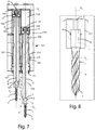
Figure 6 shows a cross section through the plane VI of the machining assembly ofFigure 5 ; -
Figure 7 shows the detail VII ofFigure 6 ; -
Figure 8 shows the detail VIII ofFigure 6 ; -
Figure 9 shows a longitudinal cross section of the machining assembly ofFigure 2 without tool; -
Figure 10 shows a longitudinal cross section of a second embodiment of the machining assembly according to the invention; -
Figure 11a - 11b show a longitudinal cross section of a third embodiment of the machining assembly according to the invention, in non-operating and operating positions, respectively; -
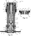
Figure 12 shows a longitudinal cross section of a fourth embodiment of the machining assembly according to the invention, in a non-operating position; -
Figure 13 shows a longitudinal cross section of the machining assembly ofFigure 12 , in an operating position; and -
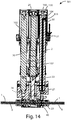
Figure 14 shows a longitudinal cross section of a fifth embodiment of the machining assembly according to the invention, in a non-operating position. -
Figures 2 - 4 show the machining assembly according to the invention labelled 101 in a first embodiment. - The
machining assembly 101 is configured for processing a semi-finished product, for example a panel made of wood or other materials, for removing material. - Said
machining assembly 101 comprises ashaft 102, in the particular embodiment aspindle shaft 102, having a longitudinal axis X1, a first end or tool-side end 103 for supporting amachining tool 1, and asecond end 106, opposite to thefirst end 103 along said longitudinal axis X1. In the particular embodiment, said tool-side end 103 is also called tool-holder end 103 as it directly supports atool 1. - Moreover, said
machining assembly 101 comprises asupport head 105 in which is formed alongitudinal housing 104 for housing therespective spindle shaft 102. - Each
spindle shaft 102 is movable from a first position, in particular a first non-operating position, to a second operating position, and vice versa, along said longitudinal axis X1 partially inside saidlongitudinal housing 104. The processing of the semi-finished product for removing material can occur in the second operating position. - A portion or
chamber 133 of saidlongitudinal housing 104 is designed to be fed pneumatically by means of a fluid, in particular a gas, in particular compressed gas, preferably compressed air, for acting on saidsecond end 106 of saidspindle shaft 102 for moving it from said first position to said second operating position, and vice versa. - Said
spindle shaft 102 has a throughchannel 2 passing between said two ends 103, 106, in order to put in fluid communication saidchamber 133 with a hole formed in said tool-holder end 103. Saidmachining assembly 101 is configured in such a way that when thechamber 133 is fed pneumatically, thespindle shaft 102 passes fro the first position to the operating position and the gas, and in particular the compressed gas in saidchamber 133, flows out by means of said hole of said tool-holder end 103. According to other embodiments, the gas can flow out also or only when thespindle shaft 102 passes from the second operating position to the first non-operating position. - In particular, the
tool 1 to be used with themachining assembly 101 according to the invention is designed for the processing of a semi-finished product for removing material, in particular swarf. Thetool 1 has at the two ends, along the relative longitudinal axis Y1, atip 3 and a coupling head orshank 4. Saidtool 1 can be removably coupled to the tool-holder end 103 of saidspindle shaft 102 by means of saidcoupling head 4. Saidmachining assembly 101 is therefore configured in such a way that when saidtool 1 is coupled to saidspindle shaft 102 and when thechamber 133 is fed pneumatically, thespindle shaft 102 passes to said operating position, thetip 3 of thetool 1 is able to act on the semi-finished product for removing material, and said gas flowing out is able to evacuate the material removed. - Moreover, according to the embodiment shown in the drawings, for example in
Figure 2 , thetool 1 comprises a throughhole tip 3 to saidcoupling head 4. Thetool 1 is configured in such a way that when it is coupled with saidspindle shaft 102 said throughhole channel 2 of saidspindle shaft 102 at the hold formed in said tool-holder end 103 in such a way that when thechamber 133 is fed pneumatically, thespindle shaft 102 is in the operating position, thetip 3 of thetool 1 can act on the semi-finished product for removing material, in particular swarf, the compressed gas can also flow from said throughhole - In other words, the compressed gas used for the selection of the
spindle 102 to be used causing a movement to the operating position (ON position) holds thespindle 10 stationary in the operating position thanks to the pressure maintained in thechamber 133, guaranteeing the perforating thrust. Simultaneously, part of the compressed gas flows out from thechannel 102, suitably calibrated, without generating an excessive pressure drop in thechamber 133 and/or in any case guaranteeing the required working pressure. - This advantageously allows for a single pneumatic user device both for the movement to the operating position of the
spindle 102 and for the blowing of the compressed gas for removing swarf. The user device is therefore controlled simultaneously by the same spindle selection valve, and like thechamber 133 is pressurised, thespindle 102 passes to the operating position and simultaneously starts to blow air from the tip of thetool 1. - The invention therefore advantageously allows the pneumatic chamber already present in the machining assembly to be used, without the need to use further devices. This also allows the overall dimensions of the machining assembly to be reduced.
- In particular, in the specific embodiment according to the invention, the through hole of the
tool 1 can have a firstcentral portion 5 at thecoupling head 4 and a second portion with a smaller diameter oro mini-channel 6 at thetip 2 in fluid communication with saidfirst portion 5. Several through holes can be provided in other embodiments. - Moreover, as can be seen from the drawings, at the tool-
holder end 103 of thespindle shaft 102 there can be ahousing 7 for thecoupling head 4 of saidtool 1. - When said
tool 1 has a through hole, the throughchannel 2 of thespindle shaft 102 can be in fluid communication with said through hole at thehousing 7. In other words, the hole formed in the tool-holder end 103 can be in fluid communication with saidhousing 7 and therefore in fluid communication with the through hole of saidtool 1 allowing the passage of the compressed gas for the evacuation of the material removed by thetool 1. - In said
housing 7 there can be an innerradial seat 8 and agasket 9, in particular an O-ring gasket, housed in saidradial seat 8. According to another embodiments, not illustrated, said gasket can be positioned directly on thecoupling head 4 of thetool 1. - The presence of the
gasket 9 advantageously avoids that the compressed gas which flows out from the throughchannel 2 to the throughhole tool 1 flows out from the tool-holder end 103. - Again, according to the invention, at the
second end 106 of thespindle shaft 102 there can be apiston body 130 designed to move thespindle shaft 102 and slide in saidchamber 133, in an integral fashion with said at least oneshaft 102. When thechamber 133 is fed pneumatically, said gas acts on saidpiston body 130, in particular on the relative upper portion, for moving said at least oneshaft 102 from said first operating position to said first non-operating position. -
Said piston body 130 has alongitudinal hole 10 not closed (unlike the prior art devices) which puts in fluid communication thechamber 133 with the throughchannel 2. When thechamber 133 is fed pneumatically, thelongitudinal hole 10 formed in thepiston body 130 allows the passage of the compressed gas from thechamber 133 to the throughchannel 2 of thespindle shaft 102. - Preferably, an
end portion 11 of the throughchannel 2 of thespindle shaft 102, at thesecond end 106, can have a smaller diameter than the diameter of the remaining portion of said throughchannel 2 in order to calibrate the flow of the gas from thechamber 133 in the throughchannel 2. The calibration enables the pressure-flow rate ratio of compressed gas to be guaranteed when it flows out from thefirst end 103 of thespindle 102, maintaining a non-excessive pressure drop in thechamber 133. In fact, the pressure in thechamber 133 must guarantee an adequate thrust to thespindle 102 in the operating position, as a reaction thrust to the perforating. - According to other embodiments, this calibration zone, which comprises a portion with a diameter smaller than the rest of the through channel can be provided in other portions of the through channel itself.
- According to the embodiment shown in the drawings, at the
second end 106 of thespindle shaft 102 there is ascrew pin 166 which can be removably coupled to saidsecond end 106 of thespindle shaft 102, in particular inside thepiston body 130. Theend portion 11 of the throughchannel 2 is formed in saidscrew pin 166. - Moreover, according to the embodiment shown in the drawings, at the head of said
screw pin 166 there can be anouter seat 12 on the diameter and there can be agasket 13, located in saidouter seat 12. Preferably, thegasket 13 can be made of PTFE. - Up to now a
machining assembly 101 has been described which comprises at least onespindle shaft 102; other embodiments can compriseseveral spindle shafts 102, as in the embodiment shown inFigures 5 and 6 . In particular, when there are at least twospindle shafts 102 themachining assembly 101 can be configured in such a way as to select each independently from the other. - This allows different perforation layouts to be obtained and to therefore perform different processing operations, and at different times with each tool.
- In that case, the
machining assembly 101 can comprise a control and management device for individually controlling eachspindle shaft 102. - The method for processing a semi-finished product by means of the
machining assembly 101 according to the invention can comprise the following steps: - a) placing the semi-finished product at the
tool 1 of at least onespindle shaft 102; - b) pneumatically feeding the
chamber 133 with compressed gas at saidspindle shaft 102; - c) moving the
spindle shaft 102 from a first non-operating position to a second operating position along the longitudinal axis X1, - d) acting on said semi-finished product for removing material by means of said
tool 1 operated pneumatically by said compressed gas; - e) evacuating the material removed by means of the compressed gas fed pneumatically in said
chamber 133. - Said steps c), d) and e) are carried out simultaneously following the same feeding of the compressed gas in the
chamber 133 of step b). - The machining assembly is configured for selecting the spindles to be used for the perforating, generating the preferred perforating layout; an axis control or pneumatic machine will then preferably be used to move the entire machining assembly to perform the stroke which generates the hole or the holes on the semi-finished product according to the preselected layout by means of the selected spindles.
-
Figure 10 shows a further embodiment of themachining assembly 101 according to the invention. Saidmachining assembly 101 differs from the embodiment described above in that the throughchannel 2 is not in fluid communication with thehousing 7 for thecoupling head 4 of thetool 1. - Said
spindle shaft 102 comprises one or more mini-channels 14,Figure 10 shows two, in fluid communication with the hole formed in the lower portion of the tool-holder end 103 and therefore in fluid communication with the throughchannel 2. - For this reason, when a normal not perforated is inserted in the
housing 7 and the machining assembly is in the operating position, the compressed gas flows out from said one or more mini-channels 14 for evacuating the material removed by saidtool 1. - A brief description is given below of the other secondary features of the
machining assembly 101 according to the invention. - Preferably, the
second end portion 106 can comprise shank means 126 positioned for being inserted in a snap-on fashion in aconical spring 125 mounted in arecess 31 defined by awall 100 of thepiston body 130 positioned for moving thespindle shaft 102. - The
machining assembly 101 can also comprise areturn spring 134 positioned for moving thespindle shaft 102 from the operating position to the non-operating position. - On the sleeve 144 a
gear 145 can be made arranged to mesh with a similar gear of anadjacent spindle shaft 102. - In other words, the
gears 145 of thespindle shafts 102 are mounted in cascade. - In the
machining assembly 101 there can also be aseal device 16, theseal device 16 being interposed between thespindle shaft 102 and thesupport sleeve 161. - The
seal device 16 can comprise afirst body 15 which makes contact with thespindle shaft 102 and is connected in a rotatable fashion, with clearance, and asecond body 17 which can be connected in a rotatable fashion to saidfirst body 15 and can be fixed, or made, in saidsupport sleeve 161 in such a way as to block saidfirst body 15 along the operational longitudinal axis X1 during movement of saidfirst element 15 along said longitudinal axis X1. -
Figures 11a - 11b show a third embodiment of themachining assembly 101 according to the invention. The same numerical references will be used for the equivalent elements which perform the same function and which are considered to be already described above. The drawings also show, with a darker colour and indicated with arrows, the passage of the gas through the conduits in fluid communication with each other. - According to the third embodiment there are a pair of
shafts 102 which are substantially equal and positioned with the relative longitudinal axes X1 parallel, and actuated in a substantially synchronous fashion when passing from said first non-operating position to said second operating position. It is evident that according to other embodiments saidmachining assembly 103 can have a smaller of greater number ofshafts 102. - At the tool-
holder end 103 of both theshafts 102 is fixed a tool-holder head 21, which comprises at least onetool 1, positioned in a removable fashion in said tool-holder head 21, for the processing of said semi-finished product for the removal of material. Twotools 1 are provided in the particular embodiment shown in the drawings. - In particular, said tool-
holder head 21 is fixed to each of saidshafts 102, in such a way that when saidshafts 102 pass between said first non-operating position and second operating position, there is a translation motion for said tool-holder head 21, parallel to each of said axes X1 (as shown in the transition fromFigure 11a to Figure 11b ). - Preferably, as shown in the drawings, the
tool 1 is positioned removably, in said tool-holder head 21, with the relative longitudinal axis Y1 normal to said longitudinal axis X1 of therespective shaft 102. - In particular, the
machining assembly 101 comprises movement means 20, having a relative shaft for transmission of rotational motion 1021, which is able to transmit the motion to means for transmission of themotion tool 1. In the particular embodiment shown inFigures 11a - 11b wherein themachining assembly 101 twoshafts 102 said shaft for transmission of the rotational motion 1021 is interposed between said pair ofshafts 102. - More specifically, said tool-
holder head 21 comprises afirst element 22 designed to receive the motion from the movement means 20, and asecond element 23 designed to impart the motion to saidtool 1. - More in detail, said
first element 22 of said tool-holder head 21 receives a first rotational motion from the tool-holder end of said shaft for the transmission of the rotational motion 1021, and saidsecond element 23 of said tool-holder head 21 imparts a second rotational motion to saidtool 1. Moreover, said shaft for transmission of the rotational motion 1021 can comprise a part with a substantially telescopic operation designed to continuously transmit a rotational motion from an assigned section of it, at least up to saidfirst element 22 of said tool-holder head 21, so that the twoshafts 102 pass, in a substantially synchronous fashion, from said first operating position to said first non-operating position. - Again, according to the invention, said tool-
holder head 21 comprises afurther hole 24 and a further through channel, designed to place in fluid communication said first hole formed in said tool-holder end 103 with saidfurther hole 24 formed in said tool-holder head 21. Saidmachining assembly 101 is configured in such a way that when saidchamber 133 is fed pneumatically, said at least oneshaft 102 moves from said first non-operating position to said second operating position, and said gas, in particular compressed air, flowing from saidfurther hole 24, or in transit through it to subsequently flow from saidmachining assembly 101, is able to evacuate the removed material. - In particular, each
tool 1, coupled in a removable fashion to said tool-holder head 21, has, at the two ends along the relative longitudinal axis Y1, respectively, atip 3, and acoupling head 4 for the removable coupling of it to saidsecond element 23 of said tool-holder head 21. Saidmachining assembly 101 is therefore configured in such a way that when saidtool 1 is coupled to saidsecond element 23 and when saidchamber 133 is fed pneumatically, saidshaft 102 passes from said first non-operating position to said second operating position, saidtip 3 of thetool 1 being able to act on the semi-finished product for removing material, and said gas flowing from saidsecond hole 24 is able to evacuate the material removed. - As in the embodiments described previously, said
tool 1 can also comprise a through hole orchannel 6, extending in the body of saidtool 1, substantially from saidtip 3 to saidcoupling head 4. Saidtool 1 is configured in such a way that when it is coupled to saidsecond element 23 of said tool-holder head 21, saidthird channel 6 puts in fluid communication with the atmosphere saidsecond hole 24 formed in said tool-holder head 21, in such a way that when saidchamber 133 is fed pneumatically, said at least oneshaft 102 passes from said first non-operating position to said second operating position, and thetip 3 of thetool 1 is able to act on the semi-finished product for the removal of material, said gas flowing finally from saidmachining assembly 101 through said throughhole 6, for evacuating the material removed. -
Figures 12 and 13 show a fourth embodiment of themachining assembly 101 according to the invention, which differs from the embodiment ofFigures 11a - 11b in that at thesecond end 106 of the at least oneshaft 102 there is apiston body 130, designed to move said at least oneshaft 102 and to slide in saidchamber 133 in an integral fashion with said at least oneshaft 102, which does not have a channel made in the body.Said piston body 130 is in fact sealed and does not put in fluid communication thechamber 133 with the throughchannel 2. - Otherwise, at said
second end 106 of the at least oneshaft 102, in particular of eachshaft 102, is formed achannel 30 in the body of the at least oneshaft 102 and designed for the passage of said gas, when thechamber 133 is fed pneumatically, fro thechamber 133 to the throughchannel 2 of said at least oneshaft 102 forming a direct fluid connection channel. - Said
machining assembly 101 is therefore configured in such a way that when saidchamber 133 is fed pneumatically, said gas acts on saidpiston body 130, in particular from the relative lower portion, for moving said at least oneshaft 102 from said second operating position (shown inFigure 13 ) to said first non-operating position (shown inFigure 12 ), and said gas passes from saidchamber 133 to said throughchannel 2 through saidchannel 30 formed in the body of the at least oneshaft 102. As shown in particular inFigure 13 , themachining assembly 101 has asecond inlet 31 of the gas formed at a lower side of thechamber 133, in such a way that when the shaft is in the operating position, the gas is fed pneumatically through saidsecond inlet 31 which acts from below, on the lower portion of thepiston body 130 to pass the shaft to the first non-operating position. Moreover, saidsecond inlet 31 is positioned in such a way as to be substantially at the same height as saidchannel 30 formed in the body of the at least oneshaft 102, when the compressed gas is fed from saidsecond inlet 31 when the shaft is in the operating position. - The embodiment of the
machining assembly 101 according toFigure 14 operates in a similar manner to themachining assembly 101 ofFigure 12 - 13 , however only oneshaft 102 has the throughchannel 2, whilst in the tool-holder head 21 is formed afurther channel 40 which is able to put in fluid connection said throughchannels 6 in said twotools 1, in such a way that the compressed gas passing through the throughchannel 2 of ashaft 102 flows out from both thetools 1 simultaneously, using a singlecompressed gas inlet 31. - The preferred embodiments have been described above and variants to the invention have been suggested, but it shall be understood that the invention may be modified and/or adapted by experts in the field without thereby departing from the scope of the inventive concept, as defined in the claims herein.
Claims (23)
- A machining assembly (101) for processing a semi-finished product, said machining assembly (101) comprising:at least one shaft (102) having a longitudinal axis (X1), a first end or tool-holder end (103) for supporting a machining tool (1), and a second end (106), opposite to the first end (103) along said longitudinal axis (X1);a support head (105) in which is formed at least one longitudinal housing (104) for housing said at least one shaft (102);said at least one shaft (102) being movable from a first non-operating position to a second operating position, and vice versa, along said longitudinal axis (X1) partially inside said longitudinal housing (104);a chamber (133) of said longitudinal housing (104) being designed to be powered pneumatically by means of a gas, in particular compressed gas, preferably compressed air, for acting on said second end (106) of said at least one shaft (102) for moving it from said non-operating position to said operating position, or vice versa;said at least one shaft (102) having a first through channel (2) passing between said two ends (103, 106), in order to put in fluid communication said chamber (133) with a first hole formed in said tool-holder end (103),said machining assembly (101) being configured so that when said chamber (133) is fed pneumatically, said at least one shaft (102) passes from said first non-operating position to said second operating position, or vice versa, and said fluid flows out via said hole of said tool-holder end (103);said at least one shaft (102) further comprising, at the relative second end (106), a channel (10, 30) for connecting fluid between said first through channel (2) and said chamber (133) in such a way as to allow the passage of said gas, when the chamber (133) if fed pneumatically, from the chamber (133) to the first through channel (2) of said at least one shaft (102).
- The machining assembly (101) according to the preceding claim, characterised in that at the second end (106) of the at least one shaft (102) there is a piston body (130) designed to move said at least one shaft (102) and to slide in said chamber (133) in an integral fashion with said at least one shaft (102), said piston body (130) having a longitudinal hole (10), parallel to said longitudinal axis (X1), not closed and designed for the passage of said gas, when the chamber (133) is fed pneumatically, from the chamber (133) to the first through channel (2) of said at least one shaft (102), said machining assembly (101) being configured in such a way that when said chamber (133) is fed pneumatically, said gas acts on said piston body (130) for moving said at least one shaft (102) from said first non-operating position to said second operating position, and said gas passes from said chamber (133) to said first through channel (2) through said longitudinal hole (10) of said piston body (130).
- The machining assembly (101) according to claim 1, characterised in that at the second end (106) of the at least one shaft (102) there is a piston body (130) designed to move said at least one shaft (102) and to slide in said chamber (133) in an integral fashion with said at least one shaft (102), in that at the second end (106) of the at least one shaft (102) a channel (30) is formed in the body of the at least one shaft (102) and designed for the passage of said gas, when the chamber (133) is fed pneumatically, from the chamber (133) to the through channel (2) of said at least one shaft (102), said machining assembly (101) being configured in such a way that when said chamber (133) is fed pneumatically, said gas acts on said piston body (130) for moving said at least one shaft (102) from said second operating position to said first non-operating position, and said gas passes from said chamber (133) to said through channel (2) through said channel (30) formed in the body of the at least one shaft (102).
- The machining assembly (101) according to any one of the preceding claims, characterised in that it comprises a tool (1) for processing said semi-finished product for removing material, said tool (1) having at the two ends, along the relative longitudinal axis (Yi), respectively, a tip (3) and a coupling head (4), said tool (1) being removably coupled to the tool-holder end (103) of said at least one shaft (102) by means of said coupling head (4), said machining assembly (101) being configured in such a way that when said tool (1) is coupled to said shaft (102) and when the chamber (133) is fed pneumatically, the shaft (102) passes from said first non-operating position to said second operating position, or vice versa, the tip (3) of the tool (1) is able to act on the semi-finished product for removing material, and said gas flowing out is able to evacuate the material removed.
- The machining assembly (101) according to the preceding claim, characterised in that said tool (1) comprises at least one through hole (5, 6) in the body of said tool (1) from said tip (3) to said coupling head (4), said tool (1) being configured in such a way that when it is coupled to said shaft (102) said through hole (5, 6) is in fluid communication with the first through channel (2) of said shaft (102) through said first hole formed in said tool-holder end (103) in such a way that when the chamber (133) is fed pneumatically, the shaft (102) passes from said first non-operating position to said second operating position, or vice versa, the tip (3) of the tool (1) is able to act on the semi-finished product to remove material, and said gas flows from said through hole (5, 6) to evacuate the material removed.
- The machining assembly (101) according to any one of claims 1 to 4, characterised in that said at least one shaft (102) comprises one or more mini-channels (14) in fluid communication with said first hole formed in the tool-holder end (103), in being configured so that, during use, when a tool is coupled to the tool-holder end (103) and the shaft (102) is in said second operating position, said fluid flows out from said one or more mini-channels (14).
- The machining assembly (101) according to any one of the previous claims, characterised in that at the tool-holder end (103) of the shaft (102) there is a housing (7) for the coupling head (4) of said tool (1).
- The machining assembly (101) according to claims 5 and 7, characterised in that said housing (7) is in fluid communication with said first hole of said through channel (2) formed in said tool-holder end (103).
- The machining assembly (101) according to claim 7 or 8, characterised in that in said housing (7) there is an inner radial seat (8) and a gasket (9), in particular an O-ring gasket, housed in said radial seat (8).
- The machining assembly (101) according to any one of the preceding claims, when dependent on claim 4, characterised in that said tool comprises a gasket at said coupling head (4).
- The machining assembly (101) according to any one of the preceding claims, characterised in that a portion (11) of the first through channel (2) of the shaft (102) has a smaller diameter than the diameter of the remaining portion of said through channel (2) in order to calibrate the flow of the fluid from the chamber (133) to the first through channel (2).
- The machining assembly (101) according to the previous claim, characterised in that said smaller diameter portion of the first through channel (2) corresponds to its end portion (11) at the second end (106) of the shaft (102).
- The machining assembly (101) according to any one of the preceding claims, characterised in that at the second end (106) of the shaft (102) there is a screw pin (166) which can be removably coupled to said second end (106) of the shaft (102).
- The machining assembly (101) according to the previous claim, characterised in that at the head of said screw pin (166) there is an outer seat (12) and in that there is a gasket (13) in said outer seat (12), preferably the gasket (13) being made of PTFE.
- The machining assembly (101) according to any one of the preceding claims, characterised in that it comprises at least two shafts (102), in particular at least two spindle shafts (102), which can be individually selected.
- The machining assembly (101) according to the previous claim, characterised in that it comprises a control and management device for individually controlling each shaft (102).
- The machining assembly (101) according to any one of claims 1 - 6 and 10 - 16, characterised in that at the tool-holder end (103) of the shaft (102) there is a tool-holder head (21) for holding at least one tool (1).
- The machining assembly (101) according to the preceding claim, characterised in that said tool-holder head (21) comprises a further hole (24) and a further through channel, designed to place in fluid communication said first hole formed in said tool-holder end (103) with said further hole (24) formed in said tool-holder head (21), said machining assembly (101) being configured in such a way that when said chamber (133) is fed pneumatically, said at least one shaft (102) moves from said first non-operating position to said second operating position, or vice versa, and said gas, flowing from said further hole (24), or in transit through it to subsequently flow from said machining assembly (101), is able to evacuate the removed material.
- The machining assembly (101) according to claim 17 or 18, characterised in that it comprises a tool (1) removably coupled to said tool-holder head (21) and in that it is configured in such a way as to be positioned in said tool-holder head (21), with the relative longitudinal axis (Y1) normal to said longitudinal axis (X1) of said at least one shaft (102).
- The machining assembly (101) according to any one of claims 17 - 19, characterised in that it comprises a pair of shafts (102) positioned with the relative axes (X1) parallel to each other, and actuated in a substantially synchronous fashion when passing from said first non-operating position to said second operating position, or vice versa, and in that said tool-holder head (21) is fixed to each of said shafts (102), in such a way that when passing between said first non-operating position and second operating position, or vice versa, said tool-holder head (21) performs a translational movement parallel to said longitudinal axis (X1).
- The machining assembly (101) according to any one of claims 17 - 20, characterised in that it comprises movement means (20) comprising a shaft for transmission of the rotational motion (1021), in that said tool-holder head (21) comprises means (22, 23) for transmission of said rotational motion from said movement means (20) to said tool (1).
- The machining assembly (101) according to claims 20 and 21, characterised in that said shaft for transmission of the rotational motion (1021) is interposed between said pair of shafts (102), and in that said shaft for transmission of the rotational motion (1021) comprises telescopic means in such a way as to be designed to transmit continuously a rotational motion by means of said transmission means (22, 23) when said shaft (102), pass, in a substantially synchronous fashion, from said first non-operating position to said second operating position, or vice versa.
- The machining assembly (101) according to any one of claims 20 - 22, characterised in that in said tool-holder head (21) there is a further channel (40) which is able to place in fluid communication said through channels (6) in two or more tools (1) supported by said tool-holder head (21).
Applications Claiming Priority (1)
| Application Number | Priority Date | Filing Date | Title |
|---|---|---|---|
| IT102018000007340A IT201800007340A1 (en) | 2018-07-19 | 2018-07-19 | Operator unit for the processing of a panel and the related processing method. |
Publications (2)
| Publication Number | Publication Date |
|---|---|
| EP3597360A1 true EP3597360A1 (en) | 2020-01-22 |
| EP3597360B1 EP3597360B1 (en) | 2022-03-16 |
Family
ID=63762904
Family Applications (1)
| Application Number | Title | Priority Date | Filing Date |
|---|---|---|---|
| EP19187402.3A Active EP3597360B1 (en) | 2018-07-19 | 2019-07-19 | Machining assembly for processing a panel |
Country Status (2)
| Country | Link |
|---|---|
| EP (1) | EP3597360B1 (en) |
| IT (1) | IT201800007340A1 (en) |
Cited By (1)
| Publication number | Priority date | Publication date | Assignee | Title |
|---|---|---|---|---|
| IT202100028367A1 (en) * | 2021-11-08 | 2023-05-08 | Scm Group Spa | Improved processing unit |
Citations (8)
| Publication number | Priority date | Publication date | Assignee | Title |
|---|---|---|---|---|
| US3502124A (en) * | 1967-10-02 | 1970-03-24 | Milton H Mater | Pole boring machine |
| US5238336A (en) * | 1992-09-29 | 1993-08-24 | Sanders Thomas A | Hand held power dowel tool |
| FR2865678A1 (en) * | 2004-02-02 | 2005-08-05 | Boucher Freres | Wood mortising tool holder for mortiser type woodworking machine, has injection device to project compressed air on smooth lateral wall along preset angle so that air is forced to drive wood chips produced by work outside mortise |
| DE102008029774A1 (en) * | 2007-06-26 | 2009-02-12 | Hsd S.P.A. | Machine for processing elements of wood or similar has gripping device and pneumatic device for cooling tool and/or blowing chips or waste away with first channel for shaft, second channel for tool with at least one outlet to surroundings |
| WO2009100708A2 (en) | 2008-02-12 | 2009-08-20 | Gerhard Koch Maschinenfabrik Gmbh & Co. Kg | Method and device for machining workpieces |
| CN201405404Y (en) | 2009-04-29 | 2010-02-17 | 上海舒平精工机械有限公司 | Woodwork hole drilling device |
| CN201405423Y (en) * | 2009-05-14 | 2010-02-17 | 杨岚 | Protective device for preventing a rill bit from releasing |
| DE102010028241A1 (en) * | 2010-04-27 | 2011-10-27 | Robert Bosch Gmbh | Minimum quantity lubrication system |
-
2018
- 2018-07-19 IT IT102018000007340A patent/IT201800007340A1/en unknown
-
2019
- 2019-07-19 EP EP19187402.3A patent/EP3597360B1/en active Active
Patent Citations (8)
| Publication number | Priority date | Publication date | Assignee | Title |
|---|---|---|---|---|
| US3502124A (en) * | 1967-10-02 | 1970-03-24 | Milton H Mater | Pole boring machine |
| US5238336A (en) * | 1992-09-29 | 1993-08-24 | Sanders Thomas A | Hand held power dowel tool |
| FR2865678A1 (en) * | 2004-02-02 | 2005-08-05 | Boucher Freres | Wood mortising tool holder for mortiser type woodworking machine, has injection device to project compressed air on smooth lateral wall along preset angle so that air is forced to drive wood chips produced by work outside mortise |
| DE102008029774A1 (en) * | 2007-06-26 | 2009-02-12 | Hsd S.P.A. | Machine for processing elements of wood or similar has gripping device and pneumatic device for cooling tool and/or blowing chips or waste away with first channel for shaft, second channel for tool with at least one outlet to surroundings |
| WO2009100708A2 (en) | 2008-02-12 | 2009-08-20 | Gerhard Koch Maschinenfabrik Gmbh & Co. Kg | Method and device for machining workpieces |
| CN201405404Y (en) | 2009-04-29 | 2010-02-17 | 上海舒平精工机械有限公司 | Woodwork hole drilling device |
| CN201405423Y (en) * | 2009-05-14 | 2010-02-17 | 杨岚 | Protective device for preventing a rill bit from releasing |
| DE102010028241A1 (en) * | 2010-04-27 | 2011-10-27 | Robert Bosch Gmbh | Minimum quantity lubrication system |
Cited By (2)
| Publication number | Priority date | Publication date | Assignee | Title |
|---|---|---|---|---|
| IT202100028367A1 (en) * | 2021-11-08 | 2023-05-08 | Scm Group Spa | Improved processing unit |
| EP4177005A3 (en) * | 2021-11-08 | 2023-07-12 | SCM Group S.p.A. | Improved working unit |
Also Published As
| Publication number | Publication date |
|---|---|
| EP3597360B1 (en) | 2022-03-16 |
| IT201800007340A1 (en) | 2020-01-19 |
Similar Documents
| Publication | Publication Date | Title |
|---|---|---|
| CN103429373B (en) | Have for by cutter fluid flushing nozzle on blade, the device that is used for inter-nal chip machining | |
| US4037982A (en) | Machine tools | |
| EP3597360B1 (en) | Machining assembly for processing a panel | |
| KR100599527B1 (en) | Branch boring machine | |
| JP7065496B2 (en) | Machines that process relatively rigid materials | |
| EP3466576B1 (en) | Automatic drilling machine for drilling in one-shot at least two holes in a crosspiece structure | |
| EP3950191B1 (en) | Chuck having a dust-proof mechanism | |
| JP6017898B2 (en) | Clamping device | |
| US5971381A (en) | Supporting cross-beam for vacuum hold-down tables designed to hold in place panels, in particular wooden panels | |
| KR20130048697A (en) | Clamp device of a drill and air drive drill | |
| US20220097117A1 (en) | Sheet metal working machine | |
| JP2009012075A (en) | Machine tools and methods for machining workpieces | |
| EP1872919B1 (en) | Machining centre for machining panels made of wood or the like | |
| KR20210047310A (en) | Devices for processing work pieces | |
| CN111183021A (en) | Machine tool | |
| EP1195207B1 (en) | Turret punch press | |
| JP6513288B2 (en) | Torch handle with pneumatically actuated jaws | |
| JPS6036887B2 (en) | center drill press | |
| JP2013094933A (en) | In-machine conveyance device for workpiece of machine tool | |
| US6270084B1 (en) | Pneumatic chuck assembly | |
| US7189033B2 (en) | Apparatus and methods for thrust sensing valves | |
| US20210291281A1 (en) | Systems and methods for forming tapered holes in workpieces | |
| KR20210149174A (en) | High pressure fluid discharge device | |
| KR20170090990A (en) | Countersinking device and associated method | |
| US12515355B1 (en) | Combination end-of-arm tool |
Legal Events
| Date | Code | Title | Description |
|---|---|---|---|
| PUAI | Public reference made under article 153(3) epc to a published international application that has entered the european phase |
Free format text: ORIGINAL CODE: 0009012 |
|
| STAA | Information on the status of an ep patent application or granted ep patent |
Free format text: STATUS: THE APPLICATION HAS BEEN PUBLISHED |
|
| AK | Designated contracting states |
Kind code of ref document: A1 Designated state(s): AL AT BE BG CH CY CZ DE DK EE ES FI FR GB GR HR HU IE IS IT LI LT LU LV MC MK MT NL NO PL PT RO RS SE SI SK SM TR |
|
| AX | Request for extension of the european patent |
Extension state: BA ME |
|
| STAA | Information on the status of an ep patent application or granted ep patent |
Free format text: STATUS: REQUEST FOR EXAMINATION WAS MADE |
|
| 17P | Request for examination filed |
Effective date: 20200722 |
|
| RBV | Designated contracting states (corrected) |
Designated state(s): AL AT BE BG CH CY CZ DE DK EE ES FI FR GB GR HR HU IE IS IT LI LT LU LV MC MK MT NL NO PL PT RO RS SE SI SK SM TR |
|
| GRAP | Despatch of communication of intention to grant a patent |
Free format text: ORIGINAL CODE: EPIDOSNIGR1 |
|
| STAA | Information on the status of an ep patent application or granted ep patent |
Free format text: STATUS: GRANT OF PATENT IS INTENDED |
|
| INTG | Intention to grant announced |
Effective date: 20211109 |
|
| GRAS | Grant fee paid |
Free format text: ORIGINAL CODE: EPIDOSNIGR3 |
|
| GRAA | (expected) grant |
Free format text: ORIGINAL CODE: 0009210 |
|
| STAA | Information on the status of an ep patent application or granted ep patent |
Free format text: STATUS: THE PATENT HAS BEEN GRANTED |
|
| AK | Designated contracting states |
Kind code of ref document: B1 Designated state(s): AL AT BE BG CH CY CZ DE DK EE ES FI FR GB GR HR HU IE IS IT LI LT LU LV MC MK MT NL NO PL PT RO RS SE SI SK SM TR |
|
| REG | Reference to a national code |
Ref country code: GB Ref legal event code: FG4D |
|
| REG | Reference to a national code |
Ref country code: CH Ref legal event code: EP Ref country code: DE Ref legal event code: R096 Ref document number: 602019012529 Country of ref document: DE |
|
| REG | Reference to a national code |
Ref country code: IE Ref legal event code: FG4D |
|
| REG | Reference to a national code |
Ref country code: AT Ref legal event code: REF Ref document number: 1475544 Country of ref document: AT Kind code of ref document: T Effective date: 20220415 |
|
| REG | Reference to a national code |
Ref country code: LT Ref legal event code: MG9D |
|
| REG | Reference to a national code |
Ref country code: NL Ref legal event code: MP Effective date: 20220316 |
|
| PG25 | Lapsed in a contracting state [announced via postgrant information from national office to epo] |
Ref country code: SE Free format text: LAPSE BECAUSE OF FAILURE TO SUBMIT A TRANSLATION OF THE DESCRIPTION OR TO PAY THE FEE WITHIN THE PRESCRIBED TIME-LIMIT Effective date: 20220316 Ref country code: RS Free format text: LAPSE BECAUSE OF FAILURE TO SUBMIT A TRANSLATION OF THE DESCRIPTION OR TO PAY THE FEE WITHIN THE PRESCRIBED TIME-LIMIT Effective date: 20220316 Ref country code: NO Free format text: LAPSE BECAUSE OF FAILURE TO SUBMIT A TRANSLATION OF THE DESCRIPTION OR TO PAY THE FEE WITHIN THE PRESCRIBED TIME-LIMIT Effective date: 20220616 Ref country code: LT Free format text: LAPSE BECAUSE OF FAILURE TO SUBMIT A TRANSLATION OF THE DESCRIPTION OR TO PAY THE FEE WITHIN THE PRESCRIBED TIME-LIMIT Effective date: 20220316 Ref country code: HR Free format text: LAPSE BECAUSE OF FAILURE TO SUBMIT A TRANSLATION OF THE DESCRIPTION OR TO PAY THE FEE WITHIN THE PRESCRIBED TIME-LIMIT Effective date: 20220316 Ref country code: BG Free format text: LAPSE BECAUSE OF FAILURE TO SUBMIT A TRANSLATION OF THE DESCRIPTION OR TO PAY THE FEE WITHIN THE PRESCRIBED TIME-LIMIT Effective date: 20220616 |
|
| PG25 | Lapsed in a contracting state [announced via postgrant information from national office to epo] |
Ref country code: LV Free format text: LAPSE BECAUSE OF FAILURE TO SUBMIT A TRANSLATION OF THE DESCRIPTION OR TO PAY THE FEE WITHIN THE PRESCRIBED TIME-LIMIT Effective date: 20220316 Ref country code: GR Free format text: LAPSE BECAUSE OF FAILURE TO SUBMIT A TRANSLATION OF THE DESCRIPTION OR TO PAY THE FEE WITHIN THE PRESCRIBED TIME-LIMIT Effective date: 20220617 Ref country code: FI Free format text: LAPSE BECAUSE OF FAILURE TO SUBMIT A TRANSLATION OF THE DESCRIPTION OR TO PAY THE FEE WITHIN THE PRESCRIBED TIME-LIMIT Effective date: 20220316 |
|
| PG25 | Lapsed in a contracting state [announced via postgrant information from national office to epo] |
Ref country code: NL Free format text: LAPSE BECAUSE OF FAILURE TO SUBMIT A TRANSLATION OF THE DESCRIPTION OR TO PAY THE FEE WITHIN THE PRESCRIBED TIME-LIMIT Effective date: 20220316 |
|
| PG25 | Lapsed in a contracting state [announced via postgrant information from national office to epo] |
Ref country code: SM Free format text: LAPSE BECAUSE OF FAILURE TO SUBMIT A TRANSLATION OF THE DESCRIPTION OR TO PAY THE FEE WITHIN THE PRESCRIBED TIME-LIMIT Effective date: 20220316 Ref country code: SK Free format text: LAPSE BECAUSE OF FAILURE TO SUBMIT A TRANSLATION OF THE DESCRIPTION OR TO PAY THE FEE WITHIN THE PRESCRIBED TIME-LIMIT Effective date: 20220316 Ref country code: RO Free format text: LAPSE BECAUSE OF FAILURE TO SUBMIT A TRANSLATION OF THE DESCRIPTION OR TO PAY THE FEE WITHIN THE PRESCRIBED TIME-LIMIT Effective date: 20220316 Ref country code: PT Free format text: LAPSE BECAUSE OF FAILURE TO SUBMIT A TRANSLATION OF THE DESCRIPTION OR TO PAY THE FEE WITHIN THE PRESCRIBED TIME-LIMIT Effective date: 20220718 Ref country code: ES Free format text: LAPSE BECAUSE OF FAILURE TO SUBMIT A TRANSLATION OF THE DESCRIPTION OR TO PAY THE FEE WITHIN THE PRESCRIBED TIME-LIMIT Effective date: 20220316 Ref country code: EE Free format text: LAPSE BECAUSE OF FAILURE TO SUBMIT A TRANSLATION OF THE DESCRIPTION OR TO PAY THE FEE WITHIN THE PRESCRIBED TIME-LIMIT Effective date: 20220316 Ref country code: CZ Free format text: LAPSE BECAUSE OF FAILURE TO SUBMIT A TRANSLATION OF THE DESCRIPTION OR TO PAY THE FEE WITHIN THE PRESCRIBED TIME-LIMIT Effective date: 20220316 |
|
| PG25 | Lapsed in a contracting state [announced via postgrant information from national office to epo] |
Ref country code: PL Free format text: LAPSE BECAUSE OF FAILURE TO SUBMIT A TRANSLATION OF THE DESCRIPTION OR TO PAY THE FEE WITHIN THE PRESCRIBED TIME-LIMIT Effective date: 20220316 Ref country code: IS Free format text: LAPSE BECAUSE OF FAILURE TO SUBMIT A TRANSLATION OF THE DESCRIPTION OR TO PAY THE FEE WITHIN THE PRESCRIBED TIME-LIMIT Effective date: 20220716 Ref country code: AL Free format text: LAPSE BECAUSE OF FAILURE TO SUBMIT A TRANSLATION OF THE DESCRIPTION OR TO PAY THE FEE WITHIN THE PRESCRIBED TIME-LIMIT Effective date: 20220316 |
|
| REG | Reference to a national code |
Ref country code: DE Ref legal event code: R097 Ref document number: 602019012529 Country of ref document: DE |
|
| PLBE | No opposition filed within time limit |
Free format text: ORIGINAL CODE: 0009261 |
|
| STAA | Information on the status of an ep patent application or granted ep patent |
Free format text: STATUS: NO OPPOSITION FILED WITHIN TIME LIMIT |
|
| PG25 | Lapsed in a contracting state [announced via postgrant information from national office to epo] |
Ref country code: DK Free format text: LAPSE BECAUSE OF FAILURE TO SUBMIT A TRANSLATION OF THE DESCRIPTION OR TO PAY THE FEE WITHIN THE PRESCRIBED TIME-LIMIT Effective date: 20220316 |
|
| 26N | No opposition filed |
Effective date: 20221219 |
|
| PG25 | Lapsed in a contracting state [announced via postgrant information from national office to epo] |
Ref country code: SI Free format text: LAPSE BECAUSE OF FAILURE TO SUBMIT A TRANSLATION OF THE DESCRIPTION OR TO PAY THE FEE WITHIN THE PRESCRIBED TIME-LIMIT Effective date: 20220316 Ref country code: MC Free format text: LAPSE BECAUSE OF FAILURE TO SUBMIT A TRANSLATION OF THE DESCRIPTION OR TO PAY THE FEE WITHIN THE PRESCRIBED TIME-LIMIT Effective date: 20220316 |
|
| REG | Reference to a national code |
Ref country code: CH Ref legal event code: PL |
|
| REG | Reference to a national code |
Ref country code: BE Ref legal event code: MM Effective date: 20220731 |
|
| PG25 | Lapsed in a contracting state [announced via postgrant information from national office to epo] |
Ref country code: LU Free format text: LAPSE BECAUSE OF NON-PAYMENT OF DUE FEES Effective date: 20220719 Ref country code: LI Free format text: LAPSE BECAUSE OF NON-PAYMENT OF DUE FEES Effective date: 20220731 Ref country code: FR Free format text: LAPSE BECAUSE OF NON-PAYMENT OF DUE FEES Effective date: 20220731 Ref country code: CH Free format text: LAPSE BECAUSE OF NON-PAYMENT OF DUE FEES Effective date: 20220731 |
|
| PG25 | Lapsed in a contracting state [announced via postgrant information from national office to epo] |
Ref country code: BE Free format text: LAPSE BECAUSE OF NON-PAYMENT OF DUE FEES Effective date: 20220731 |
|
| P01 | Opt-out of the competence of the unified patent court (upc) registered |
Effective date: 20230518 |
|
| PG25 | Lapsed in a contracting state [announced via postgrant information from national office to epo] |
Ref country code: IE Free format text: LAPSE BECAUSE OF NON-PAYMENT OF DUE FEES Effective date: 20220719 |
|
| REG | Reference to a national code |
Ref country code: AT Ref legal event code: UEP Ref document number: 1475544 Country of ref document: AT Kind code of ref document: T Effective date: 20220316 |
|
| GBPC | Gb: european patent ceased through non-payment of renewal fee |
Effective date: 20230719 |
|
| PG25 | Lapsed in a contracting state [announced via postgrant information from national office to epo] |
Ref country code: HU Free format text: LAPSE BECAUSE OF FAILURE TO SUBMIT A TRANSLATION OF THE DESCRIPTION OR TO PAY THE FEE WITHIN THE PRESCRIBED TIME-LIMIT; INVALID AB INITIO Effective date: 20190719 |
|
| PG25 | Lapsed in a contracting state [announced via postgrant information from national office to epo] |
Ref country code: MK Free format text: LAPSE BECAUSE OF FAILURE TO SUBMIT A TRANSLATION OF THE DESCRIPTION OR TO PAY THE FEE WITHIN THE PRESCRIBED TIME-LIMIT Effective date: 20220316 Ref country code: CY Free format text: LAPSE BECAUSE OF FAILURE TO SUBMIT A TRANSLATION OF THE DESCRIPTION OR TO PAY THE FEE WITHIN THE PRESCRIBED TIME-LIMIT Effective date: 20220316 Ref country code: GB Free format text: LAPSE BECAUSE OF NON-PAYMENT OF DUE FEES Effective date: 20230719 |
|
| PG25 | Lapsed in a contracting state [announced via postgrant information from national office to epo] |
Ref country code: TR Free format text: LAPSE BECAUSE OF FAILURE TO SUBMIT A TRANSLATION OF THE DESCRIPTION OR TO PAY THE FEE WITHIN THE PRESCRIBED TIME-LIMIT Effective date: 20220316 |
|
| PG25 | Lapsed in a contracting state [announced via postgrant information from national office to epo] |
Ref country code: MT Free format text: LAPSE BECAUSE OF FAILURE TO SUBMIT A TRANSLATION OF THE DESCRIPTION OR TO PAY THE FEE WITHIN THE PRESCRIBED TIME-LIMIT Effective date: 20220316 |
|
| PGFP | Annual fee paid to national office [announced via postgrant information from national office to epo] |
Ref country code: DE Payment date: 20250722 Year of fee payment: 7 |
|
| PGFP | Annual fee paid to national office [announced via postgrant information from national office to epo] |
Ref country code: IT Payment date: 20250708 Year of fee payment: 7 |
|
| PGFP | Annual fee paid to national office [announced via postgrant information from national office to epo] |
Ref country code: AT Payment date: 20250721 Year of fee payment: 7 |