EP3596858B1 - Quantum key distribution in optical communications network - Google Patents
Quantum key distribution in optical communications network Download PDFInfo
- Publication number
- EP3596858B1 EP3596858B1 EP18710843.6A EP18710843A EP3596858B1 EP 3596858 B1 EP3596858 B1 EP 3596858B1 EP 18710843 A EP18710843 A EP 18710843A EP 3596858 B1 EP3596858 B1 EP 3596858B1
- Authority
- EP
- European Patent Office
- Prior art keywords
- optical
- path
- node
- time period
- section
- Prior art date
- Legal status (The legal status is an assumption and is not a legal conclusion. Google has not performed a legal analysis and makes no representation as to the accuracy of the status listed.)
- Active
Links
- 230000003287 optical effect Effects 0.000 title claims description 340
- 238000004891 communication Methods 0.000 title claims description 51
- 238000012546 transfer Methods 0.000 claims description 42
- 238000000034 method Methods 0.000 claims description 20
- 239000002131 composite material Substances 0.000 claims description 11
- 238000004590 computer program Methods 0.000 claims description 7
- 230000006870 function Effects 0.000 description 22
- 239000000835 fiber Substances 0.000 description 21
- UIAFKZKHHVMJGS-UHFFFAOYSA-N 2,4-dihydroxybenzoic acid Chemical compound OC(=O)C1=CC=C(O)C=C1O UIAFKZKHHVMJGS-UHFFFAOYSA-N 0.000 description 12
- 230000011664 signaling Effects 0.000 description 11
- 230000005540 biological transmission Effects 0.000 description 8
- 230000004044 response Effects 0.000 description 8
- 230000003321 amplification Effects 0.000 description 7
- 238000003199 nucleic acid amplification method Methods 0.000 description 7
- 238000012545 processing Methods 0.000 description 6
- 230000008054 signal transmission Effects 0.000 description 4
- 230000001419 dependent effect Effects 0.000 description 3
- 239000013307 optical fiber Substances 0.000 description 2
- 230000002457 bidirectional effect Effects 0.000 description 1
- 230000000903 blocking effect Effects 0.000 description 1
- 238000006243 chemical reaction Methods 0.000 description 1
- 239000013078 crystal Substances 0.000 description 1
- 238000001914 filtration Methods 0.000 description 1
- 238000012986 modification Methods 0.000 description 1
- 230000004048 modification Effects 0.000 description 1
- 230000000644 propagated effect Effects 0.000 description 1
- 230000001902 propagating effect Effects 0.000 description 1
- 230000009467 reduction Effects 0.000 description 1
- 230000002269 spontaneous effect Effects 0.000 description 1
Images


Classifications
-
- H—ELECTRICITY
- H04—ELECTRIC COMMUNICATION TECHNIQUE
- H04L—TRANSMISSION OF DIGITAL INFORMATION, e.g. TELEGRAPHIC COMMUNICATION
- H04L9/00—Cryptographic mechanisms or cryptographic arrangements for secret or secure communications; Network security protocols
- H04L9/08—Key distribution or management, e.g. generation, sharing or updating, of cryptographic keys or passwords
- H04L9/0816—Key establishment, i.e. cryptographic processes or cryptographic protocols whereby a shared secret becomes available to two or more parties, for subsequent use
- H04L9/0852—Quantum cryptography
-
- H—ELECTRICITY
- H04—ELECTRIC COMMUNICATION TECHNIQUE
- H04J—MULTIPLEX COMMUNICATION
- H04J14/00—Optical multiplex systems
- H04J14/02—Wavelength-division multiplex systems
- H04J14/0227—Operation, administration, maintenance or provisioning [OAMP] of WDM networks, e.g. media access, routing or wavelength allocation
- H04J14/0254—Optical medium access
- H04J14/0272—Transmission of OAMP information
- H04J14/0275—Transmission of OAMP information using an optical service channel
-
- H—ELECTRICITY
- H04—ELECTRIC COMMUNICATION TECHNIQUE
- H04B—TRANSMISSION
- H04B10/00—Transmission systems employing electromagnetic waves other than radio-waves, e.g. infrared, visible or ultraviolet light, or employing corpuscular radiation, e.g. quantum communication
- H04B10/70—Photonic quantum communication
-
- H—ELECTRICITY
- H04—ELECTRIC COMMUNICATION TECHNIQUE
- H04B—TRANSMISSION
- H04B10/00—Transmission systems employing electromagnetic waves other than radio-waves, e.g. infrared, visible or ultraviolet light, or employing corpuscular radiation, e.g. quantum communication
- H04B10/80—Optical aspects relating to the use of optical transmission for specific applications, not provided for in groups H04B10/03 - H04B10/70, e.g. optical power feeding or optical transmission through water
- H04B10/85—Protection from unauthorised access, e.g. eavesdrop protection
-
- H—ELECTRICITY
- H04—ELECTRIC COMMUNICATION TECHNIQUE
- H04J—MULTIPLEX COMMUNICATION
- H04J14/00—Optical multiplex systems
- H04J14/02—Wavelength-division multiplex systems
- H04J14/0227—Operation, administration, maintenance or provisioning [OAMP] of WDM networks, e.g. media access, routing or wavelength allocation
- H04J14/0254—Optical medium access
- H04J14/0256—Optical medium access at the optical channel layer
-
- H—ELECTRICITY
- H04—ELECTRIC COMMUNICATION TECHNIQUE
- H04Q—SELECTING
- H04Q11/00—Selecting arrangements for multiplex systems
- H04Q11/0001—Selecting arrangements for multiplex systems using optical switching
- H04Q11/0005—Switch and router aspects
-
- H—ELECTRICITY
- H04—ELECTRIC COMMUNICATION TECHNIQUE
- H04Q—SELECTING
- H04Q11/00—Selecting arrangements for multiplex systems
- H04Q11/0001—Selecting arrangements for multiplex systems using optical switching
- H04Q11/0062—Network aspects
-
- H—ELECTRICITY
- H04—ELECTRIC COMMUNICATION TECHNIQUE
- H04Q—SELECTING
- H04Q11/00—Selecting arrangements for multiplex systems
- H04Q11/0001—Selecting arrangements for multiplex systems using optical switching
- H04Q11/0005—Switch and router aspects
- H04Q2011/0007—Construction
- H04Q2011/0016—Construction using wavelength multiplexing or demultiplexing
-
- H—ELECTRICITY
- H04—ELECTRIC COMMUNICATION TECHNIQUE
- H04Q—SELECTING
- H04Q11/00—Selecting arrangements for multiplex systems
- H04Q11/0001—Selecting arrangements for multiplex systems using optical switching
- H04Q11/0062—Network aspects
- H04Q2011/0086—Network resource allocation, dimensioning or optimisation
Definitions
- the invention relates to optical communication networks and to a node for operation in such networks.
- Encryption keys are used in the safeguarding of data from unauthorised access by making the data unreadable by anyone who does not have the correct key. Secure sharing of encryption key allows only authorised users to read protected data by using decryption. For practical reasons, sharing of these keys is commonly carried out over communication networks.
- the invention has particular application to quantum key distribution and also has application to communication of other forms of information by means of streams of single photons.
- the invention may also be used to share non-quantum keys, such as an RSA key.
- OSC optical supervisory channel
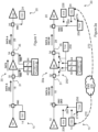
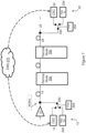
- Figure 1 A conventionally configured OSC communications network is shown in Figure 1 comprising sections of optical fibre, optical amplification sections and non-optical (e.g. electrical) sections. Non-optical sections commonly occur in long-distance optical communications links for the purpose of management or switching of signals.
- Figure 1 shows two end points 10, 20 and a remote, intermediate node or "field amplification site" 30 comprising a first port 31 connected to end point 10 over a first optical connection 18 and a second port 35 connected to end point 20 over a second optical connection 28.
- the intermediate node 30 comprises, an optical amplifier 36 (in general an EDFA) and an electrical management function 40.
- Figure 1 only shows a single connection, over which data and OSC travel in one direction (as shown in the Figure: from end point 10 to end point 20). In practice a similar connection using separate fibre will normally be present over which data and OSC travel in the opposite direction (i.e., in the Figure, from end point 20 to end point 10).
- End points 10, 20 comprise optical data communication interfaces 12, 22 and OSC equipment 14, 24.
- End points 10, 20 and intermediate node 30 are connected by optical connections, with end point 10 connected to intermediate node 30 over a first optical connection 18 and with end point 20 connected to intermediate node 30 over a second optical connection 28.
- Optical connections are typically optical fibres.
- the network shown in Figure 1 is unidirectional, i.e. with signals flowing from end point 10 to end point 20. It will be appreciated that a similar arrangement may be used to transport signals in the reverse direction from end point 20 to end point 10 and that the present invention applies to communications in both directions.
- Optical filter 16 at end point 10 combines optical data signals produced by optical data communication interfaces 12 and OSC signals produced by OSC equipment 14.
- a corresponding optical filter 26 at end point 20 separates the optical data signals and OSC signals according to wavelength, directing the optical data signals to optical data communication interface 22 and the OSC signals to OSC equipment 24.
- Optical filters 32, 34 alter onward transmission of incident optical signals dependent on the optical signal wavelength and may comprise wavelength division multiplexer/demultiplexers.
- an appropriate wavelength (e.g. 1510nm) optical separator (for example an optical filter) 32 is placed on the side of the intermediate node 30 that receives signals from end point 10 to allow the OSC signals to be separated from the data signals received via first optical connection 18 at intermediate node 30 so that the data signals are directed to optical amplification section 36, while the OSC is directed to management function 40.
- Corresponding optical filter 34 is placed on the other side of the intermediate node 30, i.e. the side that sends signals towards end point 20, to allow the regenerated OSC signals received from management function 40 to be combined onto second optical connection 28.
- the OSC transmitted over first optical connection 18 is terminated (converted from optical to electrical) at optical receiver 42 of management function 40. In this way, information may be exchanged over the OSC with node management function 40.
- the OSC is then retransmitted at optical transmitter 44 of management function 40, as an optical signal on a typical OSC wavelength to be carried over second optical connection 28 towards end point 20.
- Optical filter 34 placed on the other side of the intermediate node 30 from optical filter 32, i.e. the side that sends signals towards end point 20, combines the regenerated OSC signals received from management function 40 with the retransmitted data signals onto second optical connection 28.
- an all-optical path i.e. the third composite path
- a path may be used for quantum keys distribution.
- the path requires minimal additional hardware, given that it shares on a time-division basis hardware (i.e. the first optical port, the second path, the fourth path and the second optical port) used by another (i.e. the second composite) path.
- the present invention accordingly provides, in a second aspect, a method for operating a communications network node; in which the node comprises a first amplified optical section and a second non-optical section; in which the method comprises: receiving at the node, a first optical channel at a first wavelength and a second optical channel at a second wavelength; directing the first optical channel to the first amplified optical section; in which the node further comprises an optical bypass section; in which the method further comprises: directing the second optical channel to the second non-optical section during a first time period and directing the second optical channel to the optical bypass section during a second time period.
- the present invention accordingly provides, in a third aspect, a computer program element comprising computer program code to, when loaded into a computer system and executed thereon, cause the computer to perform the steps of the method set out above.
- the optical bypass section defined in accordance with any aspect of the invention may be capable of carrying a signal on the second optical channel from the first optical port to the second optical port.
- the signal on the second optical channel may be a single-photon stream.
- a continuous, end-to-end optical path is created to allow the transfer of an encryption key or other information by means of a stream of single photons by bypassing amplification and non-optical sections.
- reference to the transfer of an encryption key also indicates, where appropriate, communication of other information by means of a stream of single photons.
- Transmission over the end-to-end optical path may use a wavelength normally used by a signalling channel in a conventional optical network.
- the signalling channel may be disabled during key transfer and reinstated to normal operation, once the key has been transferred.
- OSC signalling channels use a wavelength, typically at 1510nm, 1610nm or 1310nm, which is "out-of-band" - outside the usual amplification band of DWDM optical amplifiers normally used for data transport.
- a problem with using signalling channels in this way is that the optical path used to transport the signalling channel is terminated (i.e. converted to electrical) at intermediate nodes in the optical communications network, for example, to allow status information to be read and modified at an optical communications network management function before being optically retransmitted.
- the standard signalling channel is unsuitable as a transmission medium for optical encryption keys.
- quantum keys have to be transported from end-to-end in the optical domain in order to preserve their state and so that the information they carry can be correctly read at the far end. It is therefore proposed to re-engineer the signalling channel, so as to provide a continuous, end-to-end optical path, with no intermediate termination (i.e. no conversion to electrical at intermediate nodes).
- the signalling channel is an optical supervisory channel (OSC).
- OSC connectivity is critical in long-haul DWDM and coarse wavelength division multiplexing (CWDM), as remote nodes are managed out of-band using the OSC.
- Use of the OSC wavelengths including 1310, 1510nm or 1610nm is widespread and benefits from low-cost, common parts.
- the attenuation at 1510nm or 161 0nm is lower than at 1310nm so allowing longer unamplified links.
- Communication at these two wavelengths also benefits from a reduction in amplified spontaneous emission (ASE) noise from the erbium-doped fibre amplifiers (EDFA) generally used in long haul DWDM links to amplify the data channels.
- ASE amplified spontaneous emission
- EDFA erbium-doped fibre amplifiers
- CV-QKD continuous-variable, quantum-key distribution
- CV-QKD has been shown to be resilient in the presence of the type of noise inherent in a DWDM link, making it particularly suitable for QKD over an amplified link.
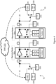
- FIG. 2a shows a communications network according to an embodiment of the invention.
- key exchange equipment 206, 226 are introduced to the end points 10, 20 and an optical bypass arrangement 250 is introduced connected between first and second ports 31, 35 at switched intermediate node 30a.
- Optical bypass arrangement 250 is controllable to enable, in a first state, "OSC operation”, i.e. connection of the OSC via management function 40, and, in a second state, "key transfer operation", i.e. end-to-end optical transfer of an encryption key.
- OSC operation i.e. connection of the OSC via management function 40
- key transfer operation i.e. end-to-end optical transfer of an encryption key.
- optical switches 260 are provided to allow key exchange equipment 206, 226 to be selectively connected via first and second optical connections 18 28, respectively, to the switched intermediate node 30a in place of the OSC equipment 14, 24 for the purposes of key transport.
- the optical switches may be implemented as MEM's using mechanical mirrors to reflect the light to different ports or arrangements where a connection is made or broken by mirrors activated, for example, using a stepper motor.
- Other suitable optical switches include piezo- and crystal-based types.
- key exchange equipment transmitter 206 uses a selected typical OSC wavelength and key exchange equipment receiver 226 receives at the selected typical OSC wavelength.
- Optical bypass arrangement 250 is shown in more detail in Figure 2b .
- bypass optical switches 252, 254 are used to selectively establish an optical bypass of the intermediate node 30 (including bypassing both optical amplification section 36 and management function 40) for the purposes of key transfer.
- Each of optical switches 252 and 254 comprises a form of optical junction, through which optical signals can follow different paths.
- optical bypass arrangement 250 comprises optical switches 252 and 254 - which are interconnected to form a bypass 255.
- the node of Figure 2b will pass data at a first wavelength via WDM 32, amplifier 36 and WDM 34; will pass, during a first time period, an OSC at a second wavelength via WDM 32, switch 252 (following a first path through the switch), management function 40, switch 254 (following a first path through the switch) and WDM 34 and will pass, during a second time period, an optical signal that may comprise a stream of single photons and may carry at least a part of an encryption key at the second wavelength via WDM 32, switch 252 (following a second path through the switch), optical bypass section 255, switch 254 (following a second path through the switch) and WDM 34.
- the OSC will follow a first path through switch 252 and a first path through switch 254 (i.e. where the switches 252, 254 occupy a first state) and during the second time period, the optical signal will follow a second path through switch 252 and a second path through switch 254 (i.e. where the switches 252, 254 occupy a second state).
- a network management system or Element Management System (EMS) 270 is also shown.
- the EMS allows all the elements to be controlled and monitored from a central application.
- the EMS 270 initiates the QKD.
- QKD may be initiated, for example, in response to a user request or an automatically generated requirement to update an out-of-date security key.
- the connection state of the optical switches 252, 254 and 260 may be remotely controlled, e.g. by Element Management System (EMS) 270.
- EMS 270 is connected over Ethernet links 272 to the OSC equipment 14, 24 at each end point 10, 20 for communication of instructions relating to switching between OSC operation and key transfer operation.
- the OSC equipment 14, 24 is connected for communication of the instructions to local optical key transport timers 256 (i.e. timers located at one or other end point 10, 20) over Ethernet links 274 and over the OSC to optical key transport timers 258 located at each intermediate switched node 30a.
- Local optical key transport timers 256 are connected to control operation of endpoint switches 260.
- Optical key transport timers 258 located at each intermediate node are connected to control operation of bypass switches 252, 254 local to that intermediate node.
- each optical key transport timer 256, 258 activates for a predetermined time interval to control the local switch or switches 260, 252, 254 to enable encryption key transfer.
- switches 260 connect OSC equipment 14, 24 to first and second optical connections 18 and 28, respectively.
- bypass optical switch 252 connects optical filter 32 on first optical connection 18 with optical receiver 42, while bypass optical switch 254 connects optical transmitter 44 with optical filter 34 on second optical connection 28.
- the OSC from OSC equipment 14 is connected through management function 40 to OSC equipment 24.
- bypass optical switch 252 disconnects optical receiver 42 and, instead, connects the signal from optical filter 32 directly or over optical fibre to bypass optical switch 254.
- bypass optical switch 254 disconnects optical transmitter 44 and, instead, connects the signal from optical filter 32 received through bypass optical switch 252 directly with optical filter 34.
- switches 260 connect key exchange equipment 206, 226 to first and second optical connections 18 28, respectively.
- an encryption key signal from key exchange equipment transmitter 206 is switched over an end-to-end, all-optical path past intermediate node 30 to key exchange equipment receiver 226.
- OSC source 14 is disconnected from first optical connection 18 for key transmission, by operation of optical switch 260 and so does not need to be disabled during key transmission.
- switch 260 at endpoint 20 may be replaced by an optical coupler/splitter.
- the data channel may continue uninterrupted through amplifier 36.
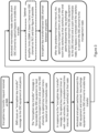
- FIG 3 shows operation of the communications networks of Figures 2a and 2b , with switched bypass, during encryption key transmission.
- EMS 270 issues an "encryption key transfer" message, for example over Ethernet links 274 to the OSC equipment 14, 24 at each end point 10, 20.
- the "encryption key transfer” message is forwarded by the OSC equipment to local optical key transport timers 256 and, over the OSC, to optical key transport timers 258 located at each intermediate node 30.
- optical key transport timers 256, 258 activate for a predetermined time interval, the end point switches 260 and remote node Switches 252, 254, as follows.
- end point switches 260 operate to disconnect the OSC equipment 14, 24 and connect key exchange equipment 206, 226 at each end point 10, 20 to the OSC to enable key transfer. That is, end point switch 260 at end point 10, switches to connect key exchange equipment transmitter 206 to the OSC on first optical connection 18 in place of OSC equipment 14. Similarly, end point switch 260 at end point 20 switches to connect key exchange equipment receiver 226 to the OSC on second optical connection 28 in place of OSC equipment 24.
- Activated bypass optical switches 252, 254 (shown in Figure 2b ) switch to divert the OSC at each intermediate node 30 to an optical bypass to enable key transfer.
- bypass optical switch 252 switches to connect the OSC received on first optical connection 18 onto the bypass.
- bypass optical switch 254 switches to connect the OSC received via bypass optical switch 252 to the OSC on second optical connection 28.
- the encryption key is now transmitted by key exchange equipment transmitter 206 and transferred to key exchange equipment 226 over the OSC using the end-to-end all optical path created.
- the data channel amplifier 36 can attempt to limit the optical noise at wavelengths close to the selected QKD channel wavelength by altering the amplification gain near that channel. This is sometimes termed "TILT" control.
- the optical key transport timers at each node revert the switches 260, 252, 254 to their normal, OSC state. According to an embodiment, this occurs at a time determined by the configuration of the timers and will occur whether or not the key transfer has successfully completed. That is, end point switch 260 at end point 10, disconnects key exchange equipment transmitter 206 from the OSC on first optical connection 18 and reconnects the OSC equipment 14. Similarly, end point switch 260 at end point 20, disconnects key exchange equipment receiver 226 from the OSC on second optical connection 28 and reconnects the OSC equipment 24. At each intermediate node, the bypass is removed and optical switches 252, 254 reconnect the OSC with management function 40.
- Figure 4 shows a similar arrangement to Figure 2a but showing two switched intermediate nodes 30a instead of one. It will be understood that the invention is not limited to any particular number of intermediate nodes but has application to any number of such nodes, i.e. where the optical output of one such node provides the optical input to the next such node.
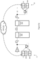
- Figures 5a , 5b and 5c show further embodiments which remove the switches of Figure 2a , 2b and 4 and, instead uses optical coupler/splitters and optical isolators.
- Figures 5a , 5b and 5c features common to earlier Figures bear the same reference numerals and will not be further discussed here, except where details are changed.
- First and second optical connections 18, 28 provide an optical path between endpoint 10, a pair of "switchless" remote nodes 30b (as described in detail, below, with reference to Figures 5b and 5c ) and endpoint 20.
- Endpoint 10 now comprises OSC equipment transmitter 14 and key exchange equipment receiver 226.
- endpoint 10 now comprises local optical key transport timer 256 connected to temporarily disable operation of OSC equipment transmitter 14 in "key transport" mode.
- OSC equipment transmitter 14 and key exchange equipment receiver 226 are connected to first optical connection 18 via optical coupler/splitter 360.
- Endpoint 20 now comprises OSC equipment receiver 24 and key exchange equipment transmitter 206.
- OSC equipment receiver 24 and key exchange equipment transmitter 206 are connected to second optical connection 28 via optical coupler 362.
- QK signals are generated at endpoint 20 - i.e. at the opposite endpoint to the OSC signals, which continue to be generated at endpoint 10.
- OSC signals and QK signals both flow over the OSC channel (i.e. using OSC wavelengths and, in general, following the OSC path, rather than the data path, between endpoints 10, 20 but in opposite directions.
- Switchless remote node 30b comprises bypass arrangement 250, which includes a bypass section comprising fibres 314, 318 and optical isolator 330 and OSC signal section comprising fibres 312, 316 and management function 40.
- Switchless remote node 30b also comprises optical junctions in the form of wavelength-independent optical couplers 310, 320, where optical coupler 310 is connected to optical filter 32 and optical coupler 320 is connected to optical filter 34.
- Each of optical coupler 310 and 320 comprises a form of optical junction, through which optical signals can follow different paths.
- the OSC signal is routed from optical filter 32, on first optical connection 18, to wavelength-independent optical coupler 310, where the OSC signal is split between two fibres 312 and 314.
- the coupler 310 may split the received OSC signal according to a power ration of 50:50 between fibres 312 and 314, although other ratios may also be selected, depending on circumstances.
- a 50:50 coupler can introduce a further 3dB power loss, which may need to be taken into account when specifying transmit power levels.
- the split ratio can be altered to raise or lower attenuation, depending on the circumstances.
- the optical coupler may be set to introduce more loss on the OSC leg (e.g. fibre 312) so as to allow the QKD leg (e.g. fibre 314)to have less loss and so operate better.
- the OSC leg e.g. fibre 312
- the QKD leg e.g. fibre 314
- an 80/20 optical split could impose ⁇ 8dB loss on the OSC leg and only ⁇ 1dB loss on the QKD leg.
- fibre 312 connects a first portion (e.g. 50%) of the OSC signal to receiver 42 of management function 40 where it is terminated (converted from optical to electrical).
- the OSC signal is retransmitted (converted from electrical to optical) at optical transmitter 44, from where it flows through fibre 316 and second optical coupler 320 to optical filter 34 on second optical connection 28.
- Second optical coupler 320 is also connected over fibre 318 to optical isolator 330.
- fibre 314 connects a second portion (e.g. the remaining 50%) of the OSC signal to optical isolator 330, however, optical isolator 330 is configured to block the OSC signal (and any optical signal) received from first optical section 18 over fibre 314 but only to pass optical signals in the opposite direction, i.e. received from second optical section 28 over fibre 318.
- the second path may therefore be better understood as extending from second optical coupler 320 through fibre 318 to optical isolator 330 and through optical isolator 330 and fibre 314 to optical coupler 310.
- the node of Figures 5a and 5b will pass data at a first wavelength via WDM 32, amplifier 36 and WDM 34. Accordingly, the node of Figures 5a and 5b will pass, during a first time period, an OSC at a second wavelength via WDM 32, optical coupler 310, management function 40, optical coupler 320 and WDM 34 and will pass, during a second time period, an optical signal that may comprise a stream of single photons and may carry at least a part of an encryption key at the second wavelength via WDM 34, optical coupler 320, optical isolator 330, optical coupler 310 and WDM 32.
- the OSC is able to follow a first and a second path of optical coupler 310 but the OSC via the second path of optical coupler 310 will be blocked by optical isolator 330.
- the OSC from transmitter 44 of management function 40 is able to follow a first path through optical coupler 320.
- the optical signal is able to follow the first and a second path through optical coupler 320 but the optical signal via the first path of optical coupler 320 will be blocked by disabled transmitter 44.
- the optical signal following the second path through optical coupler 320 will be passed by optical isolator 330 on to optical coupler 310.
- the optical signal will follow the second path through optical coupler 310 on to WDM 32.
- Figure 5c shows QK signal transmission in the opposite direction through "switchless" remote node 30b, i.e. when operating in "key transport” mode.
- encryption key transfer may be initiated at "switchless" remote node 30b in response to an "encryption key transfer” message received from EMS 270 or an alternative management node.
- optical key transport timer 258 at the (or each) intermediate node 30b activates for a predetermined time interval to disable optical transmitter 44.
- QK signal generated at key exchange equipment transmitter 206 located at endpoint 20, follows second optical connection 28 to optical filter 34.
- optical filter 34 acts as a passive optical combiner that, in addition to combining signals originally received via first optical section 18, will also will also act to divert, according to wavelength, optical signals received from second optical connection 18.
- the QK signal is diverted to optical coupler 320, where the QK signal is split between fibres 316 and 318.
- the coupler 320 may split the received QK signal at a power ration of 50:50 between fibres 316 and 318, although other ratios may also be selected, depending on circumstances.
- Fibre 316 connects a first portion (e.g. 50%) of the QK signal to optical transmitter 44, which is disabled by timer 258 and blocks the QK signal from propagating further.
- Fibre 318 connects a second portion (e.g. 50%) of the QK signal to optical isolator 330 which passes the QK signal and connects it over fibre 314 to optical coupler 310.
- optical coupler 310 is also connected to optical receiver 42 over fibre 312, for OSC signal transmission although OSC signal transmission is disabled in "key transport" mode by operation of timer 256 at endpoint 10. It will be understood that optical coupler 310 receives no signal from optical receiver 42 and passes the QK signal received through fibre 314 to optical filter 32, from where it is transmitted over first optical connection 18 and optical coupler 360 to key exchange equipment 226 at endpoint 10.
- FIG 6 shows operation of the communications networks of Figures 5a , 5b and 5c , with "switchless" bypass, during encryption key transmission.
- EMS 270 issues an "encryption key transfer" message, for example over Ethernet links 272 to the OSC equipment 14, 24 at each end point 10, 20.
- the "encryption key transfer” message is forwarded by the OSC equipment to local optical key transport timer 256 at endpoint 10 and, over the OSCs, to optical key transport timers 258 located at each intermediate node 30b (no local optical key transport timer is required at the QK transmit endpoint 20 according to this embodiment).
- each optical key transport timer 256, 258 activates for a predetermined time interval to temporarily disable, once the "encryption key transfer" message has been forwarded to optical key transport timers 258 located at each intermediate node 30b, the OSC equipment transmitter 14 at endpoint 10 and at the management function transmit interface 44 at each intermediate node 30b.
- the data channel amplifier 36 may limit gain near the OSC wavelengths, during key transfer.
- the encryption key is now transferred from end point 20 over the OSC to end point 10 (i.e. in the opposite direction to the normal operation of the OSC).
- the optical key transport timers at each node re-enable the OSC equipment transmitter 14 at endpoint 10 and the management function transmit interface 44 at each intermediate node 30b. According to an embodiment, this re-enabling occurs at a time determined by the configuration of the timers and will occur whether or not the key transfer has successfully completed.
- the OSC returns to normal operation with OSC signals propagated from endpoint 10 to endpoint 20 via intermediate nodes 30b.
- Figure 7 shows a similar arrangement to Figures 5a , 5b and 5c , with passive ("switchless") intermediate nodes 30b but with switches 260 at each endpoint 10, 20.
- endpoint 10 comprises OSC equipment transmitter 14 and key exchange equipment receiver 226, while endpoint 20 comprises OSC equipment receiver 24 and key exchange equipment transmitter 206.
- the operation of the arrangement of Figure 7 will now be described with reference to Figure 8 .
- Figure 8 shows operation of encryption key transmission in the communications networks of Figure 7 .
- EMS 270 issues an "encryption key transfer" message, for example over Ethernet links 272 to the OSC equipment 14, 24 at each end point 10, 20.
- the "encryption key transfer” message is forwarded by the OSC equipment to local optical key transport timers 256.
- each optical key transport timer 256 activates for a predetermined time interval, the end point switches 260, as follows.
- end point switch 260 operates to disconnect the OSC equipment 14, 24 and connect key exchange equipment 206, 226 at end points 20, 10, respectively, to the OSC to enable key transfer. That is, end point switch 260 at end point 10, switches to connect key exchange equipment receiver 226 to the OSC on first optical connection 18 in place of OSC equipment 14. Similarly, end point switch 260 at end point 20 switches to connect key exchange equipment transmitter 206 to the OSC on second optical connection 28 in place of OSC equipment 24.
- the "encryption key transfer" message is forwarded by the OSC equipment over the OSCs, to optical key transport timers 258 located at each intermediate node 30b).
- each optical key transport timer 258 activates for a predetermined time interval to temporarily disable the management function transmit interface 44 at each intermediate node 30b.
- the encryption key is now transmitted by key exchange equipment transmitter 206 and transferred to key exchange equipment receiver 226 located at end point 10 (i.e. in the opposite direction to the normal operation of the OSC).
- the optical key transport timers at each intermediate node re-enable the management function transmit interface 44 at each intermediate node 30b. According to an embodiment, this re-enabling occurs at a time determined by the configuration of the timers and will occur whether or not the key transfer has successfully completed.
- the optical key transport timers at each endpoint 10, 20 revert the switches 260 to their normal, OSC state. According to an embodiment, this occurs at a time determined by the configuration of the timers and will occur whether or not the key transfer has successfully completed. That is, end point switch 260 at end point 10, disconnects key exchange equipment receiver 226 from the OSC and reconnects the OSC equipment 14. Similarly, end point switch 260 at end point 20, disconnects key exchange equipment transmitter 206 from the OSC on second optical connection 28 and reconnects the OSC equipment 24. As before, the data channel amplifier 36 may limit gain near the OSC wavelengths, during key transfer.
- different optical key transport timers may have different characteristics.
- the predetermined time interval, characteristic of the optical key transport timers at the end points may differ from the predetermined time interval, characteristic of the optical key transport timers at the intermediate nodes.
- a software-controlled programmable processing device such as a microprocessor, digital signal processor or other processing device, data processing apparatus or system
- a computer program for configuring a programmable device, apparatus or system to implement the foregoing described methods is envisaged as an aspect of the present invention.
- the computer program may be embodied as source code or undergo compilation for implementation on a processing device, apparatus or system or may be embodied as object code, for example.
- the computer program is stored on a carrier medium in machine or device readable form, for example in solid-state memory, magnetic memory such as disk or tape, optically or magneto-optically readable memory such as compact disk or digital versatile disk etc., and the processing device utilises the program or a part thereof to configure it for operation.
- the computer program may be supplied from a remote source embodied in a communications medium such as an electronic signal, radio frequency carrier wave or optical carrier wave.
- a communications medium such as an electronic signal, radio frequency carrier wave or optical carrier wave.
- carrier media are also envisaged as aspects of the present invention.
Landscapes
- Engineering & Computer Science (AREA)
- Computer Networks & Wireless Communication (AREA)
- Signal Processing (AREA)
- Physics & Mathematics (AREA)
- Electromagnetism (AREA)
- Computer Security & Cryptography (AREA)
- Theoretical Computer Science (AREA)
- Optics & Photonics (AREA)
- Optical Communication System (AREA)
Description
- The invention relates to optical communication networks and to a node for operation in such networks.
- Encryption keys are used in the safeguarding of data from unauthorised access by making the data unreadable by anyone who does not have the correct key. Secure sharing of encryption key allows only authorised users to read protected data by using decryption. For practical reasons, sharing of these keys is commonly carried out over communication networks. The invention has particular application to quantum key distribution and also has application to communication of other forms of information by means of streams of single photons. The invention may also be used to share non-quantum keys, such as an RSA key.
- Long-haul or core data communications links using DWDM, commonly carry optical signals comprising two channels: data and signalling. Out-of-band optical signalling channels are used to carry status information about the DWDM network and for other purposes, for example communication between nodes, software updates to nodes and retrieving from nodes performance data such as optical power readings. The optical supervisory channel (OSC) is a dedicated, out-of-band signalling channel used to communicate and manage remote (also known as "Intermediate") nodes. A conventionally configured OSC communications network is shown in
Figure 1 comprising sections of optical fibre, optical amplification sections and non-optical (e.g. electrical) sections. Non-optical sections commonly occur in long-distance optical communications links for the purpose of management or switching of signals.Figure 1 shows twoend points first port 31 connected toend point 10 over a firstoptical connection 18 and asecond port 35 connected toend point 20 over a secondoptical connection 28. Connected between first and second ports, theintermediate node 30 comprises, an optical amplifier 36 (in general an EDFA) and anelectrical management function 40. For clarity,Figure 1 only shows a single connection, over which data and OSC travel in one direction (as shown in the Figure: fromend point 10 to end point 20). In practice a similar connection using separate fibre will normally be present over which data and OSC travel in the opposite direction (i.e., in the Figure, fromend point 20 to end point 10).End points data communication interfaces OSC equipment End points intermediate node 30 are connected by optical connections, withend point 10 connected tointermediate node 30 over a firstoptical connection 18 and withend point 20 connected tointermediate node 30 over a secondoptical connection 28. Optical connections are typically optical fibres. For simplicity the network shown inFigure 1 is unidirectional, i.e. with signals flowing fromend point 10 toend point 20. It will be appreciated that a similar arrangement may be used to transport signals in the reverse direction fromend point 20 toend point 10 and that the present invention applies to communications in both directions.Optical filter 16 atend point 10 combines optical data signals produced by opticaldata communication interfaces 12 and OSC signals produced byOSC equipment 14. A correspondingoptical filter 26 atend point 20 separates the optical data signals and OSC signals according to wavelength, directing the optical data signals to opticaldata communication interface 22 and the OSC signals toOSC equipment 24. -
Optical filters intermediate node 30 that receives signals fromend point 10 to allow the OSC signals to be separated from the data signals received via firstoptical connection 18 atintermediate node 30 so that the data signals are directed tooptical amplification section 36, while the OSC is directed tomanagement function 40. Correspondingoptical filter 34 is placed on the other side of theintermediate node 30, i.e. the side that sends signals towardsend point 20, to allow the regenerated OSC signals received frommanagement function 40 to be combined onto secondoptical connection 28. - The OSC transmitted over first
optical connection 18 is terminated (converted from optical to electrical) atoptical receiver 42 ofmanagement function 40. In this way, information may be exchanged over the OSC withnode management function 40. The OSC is then retransmitted atoptical transmitter 44 ofmanagement function 40, as an optical signal on a typical OSC wavelength to be carried over secondoptical connection 28 towardsend point 20.Optical filter 34, placed on the other side of theintermediate node 30 fromoptical filter 32, i.e. the side that sends signals towardsend point 20, combines the regenerated OSC signals received frommanagement function 40 with the retransmitted data signals onto secondoptical connection 28. -
US2012/195428 is a quantum key distribution system showing a method of increasing the physical distance over which quantum keys can be distributed. "EDFA bypass and filtering architecture enabling QKD+WDM co-existence on mid-span amplified links", Nweke N.I et al, ISBN 978-1-55752-813-1 shows an EDFA bypass arrangement. - It has been proposed to use a dense wavelength division multiplexing (DWDM) data channel for key transfer but this results in loss of a valuable resource, i.e. a full DWDM data channel.
- There is a need to provide an improved method for transporting encryption keys, including quantum keys across an optical communications network.
- The present invention is set out in the claims.
- In this way an all-optical path (i.e. the third composite path) that can carry information in the form of a stream of single photons is made available across a communications network node. Being all-optical, such a path may be used for quantum keys distribution. Advantageously, the path requires minimal additional hardware, given that it shares on a time-division basis hardware (i.e. the first optical port, the second path, the fourth path and the second optical port) used by another (i.e. the second composite) path.
- The present invention accordingly provides, in a second aspect, a method for operating a communications network node; in which the node comprises a first amplified optical section and a second non-optical section; in which the method comprises: receiving at the node, a first optical channel at a first wavelength and a second optical channel at a second wavelength; directing the first optical channel to the first amplified optical section;
in which the node further comprises an optical bypass section; in which the method further comprises: directing the second optical channel to the second non-optical section during a first time period and directing the second optical channel to the optical bypass section during a second time period. - The present invention accordingly provides, in a third aspect, a computer program element comprising computer program code to, when loaded into a computer system and executed thereon, cause the computer to perform the steps of the method set out above.
- The optical bypass section defined in accordance with any aspect of the invention may be capable of carrying a signal on the second optical channel from the first optical port to the second optical port. The signal on the second optical channel may be a single-photon stream.
- Further features of various embodiments of the invention are set out in the dependent claims appended hereto.
- In order that the present invention may be better understood, embodiments thereof will now be described, by way of example only, with reference to the accompanying drawings in which:
-
Figure 1 shows a communications network according to the prior art; -
Figures 2a ,2b ,4 ,5a ,5b ,5 and7 show communications networks according to embodiments of the invention; -
Figures 3 ,6 and8 are flow charts showing details of the operation of embodiments of the invention. - In an optical communications network according to the invention, a continuous, end-to-end optical path is created to allow the transfer of an encryption key or other information by means of a stream of single photons by bypassing amplification and non-optical sections. In the following, reference to the transfer of an encryption key also indicates, where appropriate, communication of other information by means of a stream of single photons. Transmission over the end-to-end optical path may use a wavelength normally used by a signalling channel in a conventional optical network. The signalling channel may be disabled during key transfer and reinstated to normal operation, once the key has been transferred. OSC signalling channels use a wavelength, typically at 1510nm, 1610nm or 1310nm, which is "out-of-band" - outside the usual amplification band of DWDM optical amplifiers normally used for data transport.
- A problem with using signalling channels in this way is that the optical path used to transport the signalling channel is terminated (i.e. converted to electrical) at intermediate nodes in the optical communications network, for example, to allow status information to be read and modified at an optical communications network management function before being optically retransmitted. The standard signalling channel is unsuitable as a transmission medium for optical encryption keys. In particular, quantum keys have to be transported from end-to-end in the optical domain in order to preserve their state and so that the information they carry can be correctly read at the far end. It is therefore proposed to re-engineer the signalling channel, so as to provide a continuous, end-to-end optical path, with no intermediate termination (i.e. no conversion to electrical at intermediate nodes).
- According to an embodiment, the signalling channel is an optical supervisory channel (OSC). OSC connectivity is critical in long-haul DWDM and coarse wavelength division multiplexing (CWDM), as remote nodes are managed out of-band using the OSC. Use of the OSC wavelengths including 1310, 1510nm or 1610nm is widespread and benefits from low-cost, common parts. The attenuation at 1510nm or 161 0nm is lower than at 1310nm so allowing longer unamplified links. Communication at these two wavelengths also benefits from a reduction in amplified spontaneous emission (ASE) noise from the erbium-doped fibre amplifiers (EDFA) generally used in long haul DWDM links to amplify the data channels.
- An encryption key can be transferred using a variety of methods according to various embodiments. According to an embodiment, continuous-variable, quantum-key distribution (CV-QKD) is used. CV-QKD has been shown to be resilient in the presence of the type of noise inherent in a DWDM link, making it particularly suitable for QKD over an amplified link.
-
Figure 2a shows a communications network according to an embodiment of the invention. InFigure 2a , features common withFigure 1 bear the same reference numerals and will not be further discussed here, except where details are changed. InFigure 2a ,key exchange equipment optical bypass arrangement 250 is introduced connected between first andsecond ports intermediate node 30a.Optical bypass arrangement 250 is controllable to enable, in a first state, "OSC operation", i.e. connection of the OSC viamanagement function 40, and, in a second state, "key transfer operation", i.e. end-to-end optical transfer of an encryption key. According to an embodiment, at the end points 10, 20,optical switches 260 are provided to allowkey exchange equipment optical connections 18 28, respectively, to the switchedintermediate node 30a in place of theOSC equipment exchange equipment transmitter 206 uses a selected typical OSC wavelength and keyexchange equipment receiver 226 receives at the selected typical OSC wavelength. -
Optical bypass arrangement 250 is shown in more detail inFigure 2b . According to the embodiment ofFigure 2b , bypassoptical switches optical amplification section 36 and management function 40) for the purposes of key transfer. Each ofoptical switches Figure 2b ,optical bypass arrangement 250 comprisesoptical switches 252 and 254 - which are interconnected to form abypass 255. Accordingly, the node ofFigure 2b will pass data at a first wavelength viaWDM 32,amplifier 36 andWDM 34; will pass, during a first time period, an OSC at a second wavelength viaWDM 32, switch 252 (following a first path through the switch),management function 40, switch 254 (following a first path through the switch) andWDM 34 and will pass, during a second time period, an optical signal that may comprise a stream of single photons and may carry at least a part of an encryption key at the second wavelength viaWDM 32, switch 252 (following a second path through the switch),optical bypass section 255, switch 254 (following a second path through the switch) andWDM 34. Therefore, during the first time period, the OSC will follow a first path throughswitch 252 and a first path through switch 254 (i.e. where theswitches switch 252 and a second path through switch 254 (i.e. where theswitches - A network management system or Element Management System (EMS) 270 is also shown. The EMS allows all the elements to be controlled and monitored from a central application. According to embodiments of the invention, the
EMS 270 initiates the QKD. QKD may be initiated, for example, in response to a user request or an automatically generated requirement to update an out-of-date security key. The connection state of theoptical switches EMS 270 is connected overEthernet links 272 to theOSC equipment end point OSC equipment other end point 10, 20) overEthernet links 274 and over the OSC to opticalkey transport timers 258 located at each intermediate switchednode 30a. Local opticalkey transport timers 256 are connected to control operation of endpoint switches 260. Opticalkey transport timers 258 located at each intermediate node are connected to control operation of bypass switches 252, 254 local to that intermediate node. In response to a message instructing "encryption key transfer", each opticalkey transport timer - To enable "OSC" operation, switches 260
connect OSC equipment optical connections optical switch 252 connectsoptical filter 32 on firstoptical connection 18 withoptical receiver 42, while bypassoptical switch 254 connectsoptical transmitter 44 withoptical filter 34 on secondoptical connection 28. In this way, the OSC fromOSC equipment 14 is connected throughmanagement function 40 toOSC equipment 24. To enable "key transport" operation, bypassoptical switch 252 disconnectsoptical receiver 42 and, instead, connects the signal fromoptical filter 32 directly or over optical fibre to bypassoptical switch 254. Also to enable the "key transport" operation, bypassoptical switch 254 disconnectsoptical transmitter 44 and, instead, connects the signal fromoptical filter 32 received through bypassoptical switch 252 directly withoptical filter 34. Also, in key transfer operation, switches 260 connectkey exchange equipment optical connections 18 28, respectively. In this way, an encryption key signal from keyexchange equipment transmitter 206 is switched over an end-to-end, all-optical path pastintermediate node 30 to keyexchange equipment receiver 226. In this embodiment,OSC source 14 is disconnected from firstoptical connection 18 for key transmission, by operation ofoptical switch 260 and so does not need to be disabled during key transmission. Advantageously, this removes a possible source of unreliability in disabling andre-enabling OSC source 14. According to an embodiment, switch 260 atendpoint 20 may be replaced by an optical coupler/splitter. Advantageously, during both OSC operation and key transport operation, the data channel may continue uninterrupted throughamplifier 36. -
Figure 3 shows operation of the communications networks ofFigures 2a and2b , with switched bypass, during encryption key transmission. As shown inFigure 3 , on receipt of an encryption key transfer request,EMS 270 issues an "encryption key transfer" message, for example overEthernet links 274 to theOSC equipment end point key transport timers 256 and, over the OSC, to opticalkey transport timers 258 located at eachintermediate node 30. In response to the "encryption key transfer" message, opticalkey transport timers key transport timers 258 located at each switchedintermediate node 30a, the end point switches 260 operate to disconnect theOSC equipment key exchange equipment end point end point switch 260 atend point 10, switches to connect keyexchange equipment transmitter 206 to the OSC on firstoptical connection 18 in place ofOSC equipment 14. Similarly,end point switch 260 atend point 20 switches to connect keyexchange equipment receiver 226 to the OSC on secondoptical connection 28 in place ofOSC equipment 24. Activated bypassoptical switches 252, 254 (shown inFigure 2b ) switch to divert the OSC at eachintermediate node 30 to an optical bypass to enable key transfer. That is, bypassoptical switch 252, switches to connect the OSC received on firstoptical connection 18 onto the bypass. Similarly, bypassoptical switch 254, switches to connect the OSC received via bypassoptical switch 252 to the OSC on secondoptical connection 28. The encryption key is now transmitted by keyexchange equipment transmitter 206 and transferred tokey exchange equipment 226 over the OSC using the end-to-end all optical path created. - According to an embodiment, the
data channel amplifier 36 can attempt to limit the optical noise at wavelengths close to the selected QKD channel wavelength by altering the amplification gain near that channel. This is sometimes termed "TILT" control. - After the predetermined time interval, the optical key transport timers at each node revert the
switches end point switch 260 atend point 10, disconnects keyexchange equipment transmitter 206 from the OSC on firstoptical connection 18 and reconnects theOSC equipment 14. Similarly,end point switch 260 atend point 20, disconnects keyexchange equipment receiver 226 from the OSC on secondoptical connection 28 and reconnects theOSC equipment 24. At each intermediate node, the bypass is removed andoptical switches management function 40. -
Figure 4 shows a similar arrangement toFigure 2a but showing two switchedintermediate nodes 30a instead of one. It will be understood that the invention is not limited to any particular number of intermediate nodes but has application to any number of such nodes, i.e. where the optical output of one such node provides the optical input to the next such node. -
Figures 5a ,5b and5c show further embodiments which remove the switches ofFigure 2a ,2b and4 and, instead uses optical coupler/splitters and optical isolators. InFigures 5a ,5b and5c , features common to earlier Figures bear the same reference numerals and will not be further discussed here, except where details are changed. InFigure 5a First and secondoptical connections endpoint 10, a pair of "switchless"remote nodes 30b (as described in detail, below, with reference toFigures 5b and5c ) andendpoint 20.Endpoint 10, now comprisesOSC equipment transmitter 14 and keyexchange equipment receiver 226. In addition,endpoint 10, now comprises local opticalkey transport timer 256 connected to temporarily disable operation ofOSC equipment transmitter 14 in "key transport" mode.OSC equipment transmitter 14 and keyexchange equipment receiver 226 are connected to firstoptical connection 18 via optical coupler/splitter 360.Endpoint 20, now comprisesOSC equipment receiver 24 and keyexchange equipment transmitter 206.OSC equipment receiver 24 and keyexchange equipment transmitter 206 are connected to secondoptical connection 28 viaoptical coupler 362. In contrast to the switched embodiments, inFigure 5a , QK signals are generated at endpoint 20 - i.e. at the opposite endpoint to the OSC signals, which continue to be generated atendpoint 10. InFigure 5a , OSC signals and QK signals both flow over the OSC channel (i.e. using OSC wavelengths and, in general, following the OSC path, rather than the data path, betweenendpoints -
Figure 5b shows OSC signal transmission through "switchless"remote node 30b, i.e. when not operating in "key transport" mode. InFigure 5b , features common withFigures 2a and2b bear the same reference numerals and will not be further discussed here, except where details are changed. Switchlessremote node 30b comprisesbypass arrangement 250, which includes a bypasssection comprising fibres optical isolator 330 and OSC signalsection comprising fibres management function 40. Switchlessremote node 30b also comprises optical junctions in the form of wavelength-independentoptical couplers optical coupler 310 is connected tooptical filter 32 andoptical coupler 320 is connected tooptical filter 34. Each ofoptical coupler - As shown in
Figure 5b , the OSC signal is routed fromoptical filter 32, on firstoptical connection 18, to wavelength-independentoptical coupler 310, where the OSC signal is split between twofibres coupler 310 may split the received OSC signal according to a power ration of 50:50 betweenfibres optical coupler 310,fibre 312 connects a first portion (e.g. 50%) of the OSC signal toreceiver 42 ofmanagement function 40 where it is terminated (converted from optical to electrical). After processing byManagement Function 40, the OSC signal is retransmitted (converted from electrical to optical) atoptical transmitter 44, from where it flows throughfibre 316 and secondoptical coupler 320 tooptical filter 34 on secondoptical connection 28. Secondoptical coupler 320 is also connected overfibre 318 tooptical isolator 330. Following a second path fromoptical coupler 310,fibre 314 connects a second portion (e.g. the remaining 50%) of the OSC signal tooptical isolator 330, however,optical isolator 330 is configured to block the OSC signal (and any optical signal) received from firstoptical section 18 overfibre 314 but only to pass optical signals in the opposite direction, i.e. received from secondoptical section 28 overfibre 318. The second path may therefore be better understood as extending from secondoptical coupler 320 throughfibre 318 tooptical isolator 330 and throughoptical isolator 330 andfibre 314 tooptical coupler 310. - Accordingly, the node of
Figures 5a and5b will pass data at a first wavelength viaWDM 32,amplifier 36 andWDM 34. Accordingly, the node ofFigures 5a and5b will pass, during a first time period, an OSC at a second wavelength viaWDM 32,optical coupler 310,management function 40,optical coupler 320 andWDM 34 and will pass, during a second time period, an optical signal that may comprise a stream of single photons and may carry at least a part of an encryption key at the second wavelength viaWDM 34,optical coupler 320,optical isolator 330,optical coupler 310 andWDM 32. During the first time period, the OSC is able to follow a first and a second path ofoptical coupler 310 but the OSC via the second path ofoptical coupler 310 will be blocked byoptical isolator 330. During the first time period, the OSC fromtransmitter 44 ofmanagement function 40 is able to follow a first path throughoptical coupler 320. During the second time period, the optical signal is able to follow the first and a second path throughoptical coupler 320 but the optical signal via the first path ofoptical coupler 320 will be blocked bydisabled transmitter 44. During the second time period, the optical signal following the second path throughoptical coupler 320 will be passed byoptical isolator 330 on tooptical coupler 310. During the second time period, the optical signal will follow the second path throughoptical coupler 310 on toWDM 32. -
Figure 5c shows QK signal transmission in the opposite direction through "switchless"remote node 30b, i.e. when operating in "key transport" mode. Wheretransport timer 258 is present, encryption key transfer may be initiated at "switchless"remote node 30b in response to an "encryption key transfer" message received fromEMS 270 or an alternative management node. In response to receipt of the "encryption key transfer" message, opticalkey transport timer 258 at the (or each)intermediate node 30b, activates for a predetermined time interval to disableoptical transmitter 44. Referring back toFigure 5a , QK signal generated at keyexchange equipment transmitter 206, located atendpoint 20, follows secondoptical connection 28 tooptical filter 34. According to an embodiment,optical filter 34 acts as a passive optical combiner that, in addition to combining signals originally received via firstoptical section 18, will also will also act to divert, according to wavelength, optical signals received from secondoptical connection 18. Atoptical filter 34, the QK signal is diverted tooptical coupler 320, where the QK signal is split betweenfibres coupler 320 may split the received QK signal at a power ration of 50:50 betweenfibres Fibre 316 connects a first portion (e.g. 50%) of the QK signal tooptical transmitter 44, which is disabled bytimer 258 and blocks the QK signal from propagating further.Fibre 318 connects a second portion (e.g. 50%) of the QK signal tooptical isolator 330 which passes the QK signal and connects it overfibre 314 tooptical coupler 310. As described, above,optical coupler 310 is also connected tooptical receiver 42 overfibre 312, for OSC signal transmission although OSC signal transmission is disabled in "key transport" mode by operation oftimer 256 atendpoint 10. It will be understood thatoptical coupler 310 receives no signal fromoptical receiver 42 and passes the QK signal received throughfibre 314 tooptical filter 32, from where it is transmitted over firstoptical connection 18 andoptical coupler 360 tokey exchange equipment 226 atendpoint 10. -
Figure 6 shows operation of the communications networks ofFigures 5a ,5b and5c , with "switchless" bypass, during encryption key transmission. As shown inFigure 6 , on receipt of an encryption key transfer request,EMS 270 issues an "encryption key transfer" message, for example overEthernet links 272 to theOSC equipment end point key transport timer 256 atendpoint 10 and, over the OSCs, to opticalkey transport timers 258 located at eachintermediate node 30b (no local optical key transport timer is required at the QK transmitendpoint 20 according to this embodiment). In response to the "encryption key transfer" message, each opticalkey transport timer key transport timers 258 located at eachintermediate node 30b, theOSC equipment transmitter 14 atendpoint 10 and at the management function transmitinterface 44 at eachintermediate node 30b. As before, thedata channel amplifier 36 may limit gain near the OSC wavelengths, during key transfer. The encryption key is now transferred fromend point 20 over the OSC to end point 10 (i.e. in the opposite direction to the normal operation of the OSC). After the predetermined time interval has elapsed, the optical key transport timers at each node re-enable theOSC equipment transmitter 14 atendpoint 10 and the management function transmitinterface 44 at eachintermediate node 30b. According to an embodiment, this re-enabling occurs at a time determined by the configuration of the timers and will occur whether or not the key transfer has successfully completed. The OSC returns to normal operation with OSC signals propagated fromendpoint 10 toendpoint 20 viaintermediate nodes 30b. - It will be understood that various combinations of the embodiments described, above, also fall within the scope of the present invention and one example will now be described with reference to
Figure 7. Figure 7 shows a similar arrangement toFigures 5a ,5b and5c , with passive ("switchless")intermediate nodes 30b but withswitches 260 at eachendpoint Figures 5a ,5b and5c ,endpoint 10 comprisesOSC equipment transmitter 14 and keyexchange equipment receiver 226, whileendpoint 20 comprisesOSC equipment receiver 24 and keyexchange equipment transmitter 206. The operation of the arrangement ofFigure 7 will now be described with reference toFigure 8 . -
Figure 8 shows operation of encryption key transmission in the communications networks ofFigure 7 . - As shown in
Figure 7 , on receipt of an encryption key transfer request,EMS 270 issues an "encryption key transfer" message, for example overEthernet links 272 to theOSC equipment end point key transport timers 256. In response to the "encryption key transfer" message, each opticalkey transport timer 256 activates for a predetermined time interval, the end point switches 260, as follows. Once the "encryption key transfer" message has been forwarded to opticalkey transport timers 258 located at eachintermediate node 30, theend point switch 260 operates to disconnect theOSC equipment key exchange equipment end points end point switch 260 atend point 10, switches to connect keyexchange equipment receiver 226 to the OSC on firstoptical connection 18 in place ofOSC equipment 14. Similarly,end point switch 260 atend point 20 switches to connect keyexchange equipment transmitter 206 to the OSC on secondoptical connection 28 in place ofOSC equipment 24. The "encryption key transfer" message is forwarded by the OSC equipment over the OSCs, to opticalkey transport timers 258 located at eachintermediate node 30b). In response to the "encryption key transfer" message, each opticalkey transport timer 258 activates for a predetermined time interval to temporarily disable the management function transmitinterface 44 at eachintermediate node 30b. The encryption key is now transmitted by keyexchange equipment transmitter 206 and transferred to keyexchange equipment receiver 226 located at end point 10 (i.e. in the opposite direction to the normal operation of the OSC). After the predetermined time interval has elapsed, the optical key transport timers at each intermediate node re-enable the management function transmitinterface 44 at eachintermediate node 30b. According to an embodiment, this re-enabling occurs at a time determined by the configuration of the timers and will occur whether or not the key transfer has successfully completed. After the predetermined time interval, the optical key transport timers at eachendpoint switches 260 to their normal, OSC state. According to an embodiment, this occurs at a time determined by the configuration of the timers and will occur whether or not the key transfer has successfully completed. That is,end point switch 260 atend point 10, disconnects keyexchange equipment receiver 226 from the OSC and reconnects theOSC equipment 14. Similarly,end point switch 260 atend point 20, disconnects keyexchange equipment transmitter 206 from the OSC on secondoptical connection 28 and reconnects theOSC equipment 24. As before, thedata channel amplifier 36 may limit gain near the OSC wavelengths, during key transfer. - According to an embodiment, different optical key transport timers may have different characteristics. For example, the predetermined time interval, characteristic of the optical key transport timers at the end points may differ from the predetermined time interval, characteristic of the optical key transport timers at the intermediate nodes.
- Where for simplicity a single fibre is shown in the Figures, with traffic (data, DWDM) and OSC in one direction the skilled person will understand that a second fibre with all elements reversed may be provided to carry traffic and OSC in the opposite direction for bidirectional operation. It will be understood that a second fibre would also allow QKD to take place in the opposite direction to QKD through the first fibre. Where specific optical elements are described for purposes such as separating, combining, blocking or passing an optical signal, whether on the basis of wavelength, power or otherwise, the skilled person will also understand that these elements are merely examples and that alternative elements may be used, where available.
- Insofar as embodiments of the invention described are implementable, at least in part, using a software-controlled programmable processing device, such as a microprocessor, digital signal processor or other processing device, data processing apparatus or system, it will be appreciated that a computer program for configuring a programmable device, apparatus or system to implement the foregoing described methods is envisaged as an aspect of the present invention. The computer program may be embodied as source code or undergo compilation for implementation on a processing device, apparatus or system or may be embodied as object code, for example.
- Suitably, the computer program is stored on a carrier medium in machine or device readable form, for example in solid-state memory, magnetic memory such as disk or tape, optically or magneto-optically readable memory such as compact disk or digital versatile disk etc., and the processing device utilises the program or a part thereof to configure it for operation. The computer program may be supplied from a remote source embodied in a communications medium such as an electronic signal, radio frequency carrier wave or optical carrier wave. Such carrier media are also envisaged as aspects of the present invention.
- It will be understood by those skilled in the art that, although the present invention has been described in relation to the above described example embodiments, the invention is not limited thereto and that there are many possible variations and modifications which fall within the scope of the invention as set out in the appended claims.
- The scope of the present invention includes any novel features or combination of features disclosed herein. The applicant hereby gives notice that new claims may be formulated to such features or combination of features during prosecution of this application or of any such further applications derived therefrom. In particular, with reference to the appended claims, features from dependent claims may be combined with those of the independent claims and features from respective independent claims may be combined in any appropriate manner and not merely in the specific combinations enumerated in the claims.
Claims (21)
- A communications network node 250 comprising: first 31 and second 35 optical ports, a first amplified optical section connected between the first and second optical ports and a second non-optical section connected between the first and second optical ports;in which the communications node also comprises a first optical filter 32 comprising a first path for selected optical channels at a first wavelength and second path for selected optical channels at a second wavelength;in which the communications node also comprises a second optical filter comprising a third path for selected optical channels at the first wavelength and fourth path for selected optical channels at the second wavelength;in which a first composite path through the node comprises, in an order, the first optical port 31, the first path, the first amplified optical section, the third path and the second optical port 35;characterised in that the communications node 250 also comprises an optical bypass section 255 connected between the first and second optical ports and first and second optical junctions ;in which the first optical junction comprising a fifth path and a sixth path; and in which the second optical junction comprising a seventh path and an eighth path; in which a second composite path through the node comprises, in an order, the first optical port, the second path, the fifth path, the second non optical section, the seventh path, the fourth path and the second optical port;in which a third composite path through the node comprises, in an order, the first optical port, the second path, the sixth path, the optical bypass section, the eighth path, the fourth path and the second optical port;in which the node is configured to pass a first optical channel at a first wavelength over the first composite path andin which the node is configured to pass a second optical channel at a second wavelength over the second composite path during a first time period andthe node is configured to pass a second optical channel at a second wavelength over the third composite path during a second time period so as to create a continuous, end-to-end optical path to allow the transfer of information by means of a stream of single photons,wherein the third composite path is different to second composite path,and wherein, during the first time period, the second composite path carries an optical service channel.
- The communications node of claim 1, in which the second optical channel comprises a classic waveform signal in the first time period and a single-photon stream in the second time period.
- The communications node of any of the preceding claims, in which the second optical channel comprises at least a part of an encryption key in the second time period.
- The communications node of any of the preceding claims, in which the first optical junction comprises a first switch 252 and the second optical junction comprises a second switch 254.
- The communications node of claim 4, in which the first switch is configured to connect the second path to the second non-optical section during the first time period and to connect the second path to the optical bypass section during the second time period.
- The communications node of any of claims 4 to 5, in which the second switch is configured to connect the fourth path to the second non-optical section during the first time period and to connect the fourth path to the optical bypass section during the second time period.
- The communications node of any of claims 1 to 3, in which the node is configured to pass the second optical channel over the second non optical section in a direction from the first optical junction to the second optical junction; and to pass the second optical channel over the optical bypass section in a direction from the second optical junction to the first optical junction.
- The communications node of any of claims 1 to 3 and 7 in which the optical bypass section comprises an optical isolator configured to pass optical signals received from the second optical junction and to block optical signals received from the first optical junction.
- The communications node of any of claims 1 to 3 and 7 to 8, in which the second non-optical section comprises an optical transmitter, in which the node is configured to enable the optical transmitter during the first time period and to disable the optical transmitter during the second time period.
- The communications node of any of the preceding claims, in which the node comprises a timer 258, in which the duration of the second time period is a pre-set characteristic of the timer.
- A communications network comprising a first and a second terminating node and a plurality of intermediate nodes, each intermediate node according to the communications node of any of the preceding claims, in which the second time period is indicated by a timing signal, in which the timing signal is shared with the plurality of intermediate nodes to influence operation of each intermediate node.
- The communications network of claim 11, in which the timing signal is shared with the first and a second terminating nodes of the communications network to influence operation of the terminating nodes.
- A communications network comprising the communications node of any of claims 1 to 10.
- A method for operating a communications network node 250; in which the node comprises a first amplified optical section connected between first 31 and second 35 optical ports and a second non-optical section connected between the first and second optical ports; in which the method comprises:receiving at the node, a first optical channel at a first wavelength and a second optical channel at a second wavelength;directing the first optical channel to the first amplified optical section;characterised in that the node further comprises an optical bypass section 255 connected between the first and second optical ports; in which the method further comprises:directing the second optical channel to the second non-optical section during a first time period andthe method further comprises directing the second optical channel to the optical bypass section during a second time period, so as to create a continuous, end-to-end optical path to allow the transfer of information by means of a stream of single photons,wherein the optical bypass is different to second non-optical section,and wherein, during the first time period, the second non-optical section carries an optical service channel.
- The method of claim 14, in which the first optical channel occupies a first wavelength and in which, during both the first and second time periods, the second optical channel occupies a second wavelength.
- The method of any of claims 14 and 15, comprising:during the first time period, passing the second optical channel over a first path of a first optical junction and a first path of a second optical junction; andduring the second time period, passing the second optical channel over a second path of the first optical junction and a second path of the second optical junction.
- The method of any of claims 14 to 16, comprising receiving at the node a timing signal and deriving from the timing signal an indication of the second time period.
- The method of any of claims 14 to 17, comprising sharing the timing signal with a first and a second terminating node of the communications network to influence operation of the terminating nodes by at least one of:in the second time period, establishing at the first terminating node a connection between a source of a single-photon stream and the node; andin the second time period, establishing at the second terminating node a connection between a destination of the single-photon stream and the node.
- The method of any of claims 14 to 18, in which the method comprises during the first time period, passing the second optical channel through the node over the second non-optical section in a first direction; and
during the second time period, passing the second optical channel through the node over the optical bypass section in a second direction opposed to the first direction. - The method of any one of claims 14 and 19, comprising enabling an optical transmitter comprised in the second non-optical section during the first time period and disabling the optical transmitter during the second time period.
- A computer program comprising instructions to cause the communication network node of any one of claims 1 to 10 to execute the steps of the method of any one of claims 14 to 20.
Applications Claiming Priority (2)
| Application Number | Priority Date | Filing Date | Title |
|---|---|---|---|
| EP17161330 | 2017-03-16 | ||
| PCT/EP2018/055948 WO2018166920A1 (en) | 2017-03-16 | 2018-03-09 | Quantum key distribution in optical communications network |
Publications (2)
| Publication Number | Publication Date |
|---|---|
| EP3596858A1 EP3596858A1 (en) | 2020-01-22 |
| EP3596858B1 true EP3596858B1 (en) | 2023-09-27 |
Family
ID=58401375
Family Applications (1)
| Application Number | Title | Priority Date | Filing Date |
|---|---|---|---|
| EP18710843.6A Active EP3596858B1 (en) | 2017-03-16 | 2018-03-09 | Quantum key distribution in optical communications network |
Country Status (4)
| Country | Link |
|---|---|
| US (1) | US11165570B2 (en) |
| EP (1) | EP3596858B1 (en) |
| CN (1) | CN110419180B (en) |
| WO (1) | WO2018166920A1 (en) |
Families Citing this family (5)
| Publication number | Priority date | Publication date | Assignee | Title |
|---|---|---|---|---|
| US10892822B2 (en) | 2017-02-01 | 2021-01-12 | British Telecommunications Public Limited Company | Optical fiber event location |
| WO2019016263A1 (en) | 2017-07-20 | 2019-01-24 | British Telecommunications Public Limited Company | Optical fibre |
| KR102595369B1 (en) * | 2019-09-16 | 2023-10-30 | 주식회사 케이티 | Method, apparatus and system for quantum cryptography key distribution |
| CN110868297A (en) * | 2019-11-19 | 2020-03-06 | 南昌航空大学 | Method for improving RSA reverse decryption difficulty |
| EP4369649A1 (en) * | 2022-11-10 | 2024-05-15 | Terra Quantum AG | Method and system for quantum key distribution |
Family Cites Families (21)
| Publication number | Priority date | Publication date | Assignee | Title |
|---|---|---|---|---|
| JPH09321701A (en) | 1996-05-31 | 1997-12-12 | Fujitsu Ltd | Optical communication system and optical amplifier |
| WO2006014298A2 (en) | 2004-07-02 | 2006-02-09 | Magiq Technologies, Inc. | Qkd cascaded network with loop-back capability |
| US7889868B2 (en) * | 2005-09-30 | 2011-02-15 | Verizon Business Global Llc | Quantum key distribution system |
| US7809268B2 (en) * | 2006-03-13 | 2010-10-05 | Cisco Technology, Inc. | Integrated optical service channel and quantum key distribution channel |
| EP2266250A1 (en) | 2008-03-13 | 2010-12-29 | University College Cork-National University of Ireland, Cork | An optical communication system and method for secure data communication using quantum key distribution |
| AU2009338643A1 (en) * | 2009-01-29 | 2011-08-18 | Telefonaktiebolaget Lm Ericsson (Publ) | Optical communications network node and method of controlling data transmission between optical communications network nodes |
| EP2721751B1 (en) | 2011-06-20 | 2017-08-16 | British Telecommunications Public Limited Company | Communications network |
| EP2680606A1 (en) | 2012-06-29 | 2014-01-01 | British Telecommunications Public Limited Company | Optical signal routing |
| EP2775733A1 (en) | 2013-03-05 | 2014-09-10 | British Telecommunications public limited company | Communications network |
| GB201305801D0 (en) | 2013-03-28 | 2013-05-15 | British Telecomm | Optical switch |
| GB201305818D0 (en) | 2013-03-28 | 2013-05-15 | British Telecomm | Signal routing |
| GB201305985D0 (en) | 2013-04-03 | 2013-05-15 | British Telecomm | Optical switch |
| EP2797247A1 (en) | 2013-04-24 | 2014-10-29 | British Telecommunications Public Limited Company | Optical data transmission |
| GB2514134B (en) * | 2013-05-14 | 2016-05-25 | Toshiba Res Europe Ltd | A signal manipulator for a quantum communication system |
| WO2015052468A1 (en) | 2013-10-11 | 2015-04-16 | British Telecommunications Public Limited Company | Optical data transmission method and apparatus |
| CN103929251B (en) | 2014-04-22 | 2017-05-24 | 华南师范大学 | Low noise QKD and WDM classic communication network compatible method and device |
| CN104092538B (en) | 2014-07-15 | 2017-04-12 | 华南师范大学 | Multi-user wavelength division multiplexing QKD network system and secret key distributing and sharing method thereof |
| CN107465502A (en) * | 2016-06-02 | 2017-12-12 | 华为技术有限公司 | A kind of quantum communications method and relevant apparatus |
| US20200033543A1 (en) | 2016-09-30 | 2020-01-30 | British Telecommunications Public Limited Company | Optical fibre joint |
| US10892822B2 (en) | 2017-02-01 | 2021-01-12 | British Telecommunications Public Limited Company | Optical fiber event location |
| WO2019016263A1 (en) | 2017-07-20 | 2019-01-24 | British Telecommunications Public Limited Company | Optical fibre |
-
2018
- 2018-03-09 WO PCT/EP2018/055948 patent/WO2018166920A1/en unknown
- 2018-03-09 CN CN201880018103.7A patent/CN110419180B/en active Active
- 2018-03-09 EP EP18710843.6A patent/EP3596858B1/en active Active
- 2018-03-09 US US16/494,564 patent/US11165570B2/en active Active
Also Published As
| Publication number | Publication date |
|---|---|
| WO2018166920A1 (en) | 2018-09-20 |
| CN110419180B (en) | 2021-02-09 |
| US20210126778A1 (en) | 2021-04-29 |
| EP3596858A1 (en) | 2020-01-22 |
| CN110419180A (en) | 2019-11-05 |
| US11165570B2 (en) | 2021-11-02 |
Similar Documents
| Publication | Publication Date | Title |
|---|---|---|
| EP3596858B1 (en) | Quantum key distribution in optical communications network | |
| US8131149B2 (en) | Optical routing device and optical network using same | |
| US6771905B1 (en) | Optical transmission systems including optical switching devices, control apparatuses, and methods | |
| AU2001292558B2 (en) | Optical transmission systems including optical protection systems, apparatuses, and methods | |
| US6922529B2 (en) | Optical communications systems, devices, and methods | |
| US5712932A (en) | Dynamically reconfigurable WDM optical communication systems with optical routing systems | |
| US6307986B1 (en) | Protection switching in bidirectional WDM optical communication networks with transponders | |
| US20120183294A1 (en) | Colorless, directionless, and gridless optical network, node, and method | |
| EP1613001A1 (en) | Hybrid optical ring network | |
| JPH10224828A (en) | Optical transmitter | |
| WO2015100575A1 (en) | Optical add-drop multiplexer and branching unit | |
| US10097304B2 (en) | Optical switch, an optical switching apparatus, an optical communications network node and an optical communications network | |
| US7120360B2 (en) | System and method for protecting traffic in a hubbed optical ring network | |
| CA2453710C (en) | Wdm ring network for flexible connections | |
| GB2560564A (en) | Communications Network Node | |
| US6304351B1 (en) | Universal branching unit | |
| JPH0936834A (en) | Optical branching and inserting circuit | |
| US7110638B2 (en) | Reconfigurable optical node with distributed spectral filtering | |
| US20050196169A1 (en) | System and method for communicating traffic between optical rings | |
| EP3685530B1 (en) | Mode coupling receiver for quantum communications and quantum communication system comprising said receiver | |
| US6616348B1 (en) | Method and optical communication network for bidirectional protection protocols | |
| JP5912932B2 (en) | Optical transmission equipment | |
| GB2359433A (en) | Optical regenerating wavelength dependant routing interface | |
| CN112088501B (en) | Single-fiber looped network structure | |
| US20050095001A1 (en) | Method and system for increasing network capacity in an optical network |
Legal Events
| Date | Code | Title | Description |
|---|---|---|---|
| STAA | Information on the status of an ep patent application or granted ep patent |
Free format text: STATUS: UNKNOWN |
|
| STAA | Information on the status of an ep patent application or granted ep patent |
Free format text: STATUS: THE INTERNATIONAL PUBLICATION HAS BEEN MADE |
|
| PUAI | Public reference made under article 153(3) epc to a published international application that has entered the european phase |
Free format text: ORIGINAL CODE: 0009012 |
|
| STAA | Information on the status of an ep patent application or granted ep patent |
Free format text: STATUS: REQUEST FOR EXAMINATION WAS MADE |
|
| 17P | Request for examination filed |
Effective date: 20190830 |
|
| AK | Designated contracting states |
Kind code of ref document: A1 Designated state(s): AL AT BE BG CH CY CZ DE DK EE ES FI FR GB GR HR HU IE IS IT LI LT LU LV MC MK MT NL NO PL PT RO RS SE SI SK SM TR |
|
| AX | Request for extension of the european patent |
Extension state: BA ME |
|
| DAV | Request for validation of the european patent (deleted) | ||
| DAX | Request for extension of the european patent (deleted) | ||
| STAA | Information on the status of an ep patent application or granted ep patent |
Free format text: STATUS: EXAMINATION IS IN PROGRESS |
|
| STAA | Information on the status of an ep patent application or granted ep patent |
Free format text: STATUS: EXAMINATION IS IN PROGRESS |
|
| 17Q | First examination report despatched |
Effective date: 20211124 |
|
| RAP3 | Party data changed (applicant data changed or rights of an application transferred) |
Owner name: BRITISH TELECOMMUNICATIONS PUBLIC LIMITED COMPANY |
|
| GRAP | Despatch of communication of intention to grant a patent |
Free format text: ORIGINAL CODE: EPIDOSNIGR1 |
|
| STAA | Information on the status of an ep patent application or granted ep patent |
Free format text: STATUS: GRANT OF PATENT IS INTENDED |
|
| INTG | Intention to grant announced |
Effective date: 20230504 |
|
| P01 | Opt-out of the competence of the unified patent court (upc) registered |
Effective date: 20230623 |
|
| GRAS | Grant fee paid |
Free format text: ORIGINAL CODE: EPIDOSNIGR3 |
|
| GRAA | (expected) grant |
Free format text: ORIGINAL CODE: 0009210 |
|
| STAA | Information on the status of an ep patent application or granted ep patent |
Free format text: STATUS: THE PATENT HAS BEEN GRANTED |
|
| AK | Designated contracting states |
Kind code of ref document: B1 Designated state(s): AL AT BE BG CH CY CZ DE DK EE ES FI FR GB GR HR HU IE IS IT LI LT LU LV MC MK MT NL NO PL PT RO RS SE SI SK SM TR |
|
| REG | Reference to a national code |
Ref country code: GB Ref legal event code: FG4D |
|
| REG | Reference to a national code |
Ref country code: CH Ref legal event code: EP |
|
| REG | Reference to a national code |
Ref country code: DE Ref legal event code: R096 Ref document number: 602018058227 Country of ref document: DE |
|
| REG | Reference to a national code |
Ref country code: IE Ref legal event code: FG4D |
|
| REG | Reference to a national code |
Ref country code: LT Ref legal event code: MG9D |
|
| PG25 | Lapsed in a contracting state [announced via postgrant information from national office to epo] |
Ref country code: GR Free format text: LAPSE BECAUSE OF FAILURE TO SUBMIT A TRANSLATION OF THE DESCRIPTION OR TO PAY THE FEE WITHIN THE PRESCRIBED TIME-LIMIT Effective date: 20231228 |
|
| PG25 | Lapsed in a contracting state [announced via postgrant information from national office to epo] |
Ref country code: SE Free format text: LAPSE BECAUSE OF FAILURE TO SUBMIT A TRANSLATION OF THE DESCRIPTION OR TO PAY THE FEE WITHIN THE PRESCRIBED TIME-LIMIT Effective date: 20230927 Ref country code: RS Free format text: LAPSE BECAUSE OF FAILURE TO SUBMIT A TRANSLATION OF THE DESCRIPTION OR TO PAY THE FEE WITHIN THE PRESCRIBED TIME-LIMIT Effective date: 20230927 Ref country code: NO Free format text: LAPSE BECAUSE OF FAILURE TO SUBMIT A TRANSLATION OF THE DESCRIPTION OR TO PAY THE FEE WITHIN THE PRESCRIBED TIME-LIMIT Effective date: 20231227 Ref country code: LV Free format text: LAPSE BECAUSE OF FAILURE TO SUBMIT A TRANSLATION OF THE DESCRIPTION OR TO PAY THE FEE WITHIN THE PRESCRIBED TIME-LIMIT Effective date: 20230927 Ref country code: LT Free format text: LAPSE BECAUSE OF FAILURE TO SUBMIT A TRANSLATION OF THE DESCRIPTION OR TO PAY THE FEE WITHIN THE PRESCRIBED TIME-LIMIT Effective date: 20230927 Ref country code: HR Free format text: LAPSE BECAUSE OF FAILURE TO SUBMIT A TRANSLATION OF THE DESCRIPTION OR TO PAY THE FEE WITHIN THE PRESCRIBED TIME-LIMIT Effective date: 20230927 Ref country code: GR Free format text: LAPSE BECAUSE OF FAILURE TO SUBMIT A TRANSLATION OF THE DESCRIPTION OR TO PAY THE FEE WITHIN THE PRESCRIBED TIME-LIMIT Effective date: 20231228 Ref country code: FI Free format text: LAPSE BECAUSE OF FAILURE TO SUBMIT A TRANSLATION OF THE DESCRIPTION OR TO PAY THE FEE WITHIN THE PRESCRIBED TIME-LIMIT Effective date: 20230927 |
|
| REG | Reference to a national code |
Ref country code: NL Ref legal event code: MP Effective date: 20230927 |
|
| REG | Reference to a national code |
Ref country code: AT Ref legal event code: MK05 Ref document number: 1616441 Country of ref document: AT Kind code of ref document: T Effective date: 20230927 |
|
| PG25 | Lapsed in a contracting state [announced via postgrant information from national office to epo] |
Ref country code: NL Free format text: LAPSE BECAUSE OF FAILURE TO SUBMIT A TRANSLATION OF THE DESCRIPTION OR TO PAY THE FEE WITHIN THE PRESCRIBED TIME-LIMIT Effective date: 20230927 |
|
| PG25 | Lapsed in a contracting state [announced via postgrant information from national office to epo] |
Ref country code: IS Free format text: LAPSE BECAUSE OF FAILURE TO SUBMIT A TRANSLATION OF THE DESCRIPTION OR TO PAY THE FEE WITHIN THE PRESCRIBED TIME-LIMIT Effective date: 20240127 |
|
| PG25 | Lapsed in a contracting state [announced via postgrant information from national office to epo] |
Ref country code: AT Free format text: LAPSE BECAUSE OF FAILURE TO SUBMIT A TRANSLATION OF THE DESCRIPTION OR TO PAY THE FEE WITHIN THE PRESCRIBED TIME-LIMIT Effective date: 20230927 |
|
| PG25 | Lapsed in a contracting state [announced via postgrant information from national office to epo] |
Ref country code: ES Free format text: LAPSE BECAUSE OF FAILURE TO SUBMIT A TRANSLATION OF THE DESCRIPTION OR TO PAY THE FEE WITHIN THE PRESCRIBED TIME-LIMIT Effective date: 20230927 |
|
| PG25 | Lapsed in a contracting state [announced via postgrant information from national office to epo] |
Ref country code: SM Free format text: LAPSE BECAUSE OF FAILURE TO SUBMIT A TRANSLATION OF THE DESCRIPTION OR TO PAY THE FEE WITHIN THE PRESCRIBED TIME-LIMIT Effective date: 20230927 Ref country code: RO Free format text: LAPSE BECAUSE OF FAILURE TO SUBMIT A TRANSLATION OF THE DESCRIPTION OR TO PAY THE FEE WITHIN THE PRESCRIBED TIME-LIMIT Effective date: 20230927 Ref country code: IS Free format text: LAPSE BECAUSE OF FAILURE TO SUBMIT A TRANSLATION OF THE DESCRIPTION OR TO PAY THE FEE WITHIN THE PRESCRIBED TIME-LIMIT Effective date: 20240127 Ref country code: ES Free format text: LAPSE BECAUSE OF FAILURE TO SUBMIT A TRANSLATION OF THE DESCRIPTION OR TO PAY THE FEE WITHIN THE PRESCRIBED TIME-LIMIT Effective date: 20230927 Ref country code: EE Free format text: LAPSE BECAUSE OF FAILURE TO SUBMIT A TRANSLATION OF THE DESCRIPTION OR TO PAY THE FEE WITHIN THE PRESCRIBED TIME-LIMIT Effective date: 20230927 Ref country code: CZ Free format text: LAPSE BECAUSE OF FAILURE TO SUBMIT A TRANSLATION OF THE DESCRIPTION OR TO PAY THE FEE WITHIN THE PRESCRIBED TIME-LIMIT Effective date: 20230927 Ref country code: AT Free format text: LAPSE BECAUSE OF FAILURE TO SUBMIT A TRANSLATION OF THE DESCRIPTION OR TO PAY THE FEE WITHIN THE PRESCRIBED TIME-LIMIT Effective date: 20230927 Ref country code: SK Free format text: LAPSE BECAUSE OF FAILURE TO SUBMIT A TRANSLATION OF THE DESCRIPTION OR TO PAY THE FEE WITHIN THE PRESCRIBED TIME-LIMIT Effective date: 20230927 Ref country code: PT Free format text: LAPSE BECAUSE OF FAILURE TO SUBMIT A TRANSLATION OF THE DESCRIPTION OR TO PAY THE FEE WITHIN THE PRESCRIBED TIME-LIMIT Effective date: 20240129 |
|
| PGFP | Annual fee paid to national office [announced via postgrant information from national office to epo] |
Ref country code: DE Payment date: 20240220 Year of fee payment: 7 Ref country code: GB Payment date: 20240220 Year of fee payment: 7 |
|
| PG25 | Lapsed in a contracting state [announced via postgrant information from national office to epo] |
Ref country code: PL Free format text: LAPSE BECAUSE OF FAILURE TO SUBMIT A TRANSLATION OF THE DESCRIPTION OR TO PAY THE FEE WITHIN THE PRESCRIBED TIME-LIMIT Effective date: 20230927 Ref country code: IT Free format text: LAPSE BECAUSE OF FAILURE TO SUBMIT A TRANSLATION OF THE DESCRIPTION OR TO PAY THE FEE WITHIN THE PRESCRIBED TIME-LIMIT Effective date: 20230927 |
|
| PGFP | Annual fee paid to national office [announced via postgrant information from national office to epo] |
Ref country code: FR Payment date: 20240220 Year of fee payment: 7 |
|
| REG | Reference to a national code |
Ref country code: DE Ref legal event code: R097 Ref document number: 602018058227 Country of ref document: DE |
|
| PG25 | Lapsed in a contracting state [announced via postgrant information from national office to epo] |
Ref country code: DK Free format text: LAPSE BECAUSE OF FAILURE TO SUBMIT A TRANSLATION OF THE DESCRIPTION OR TO PAY THE FEE WITHIN THE PRESCRIBED TIME-LIMIT Effective date: 20230927 |
|
| PG25 | Lapsed in a contracting state [announced via postgrant information from national office to epo] |
Ref country code: DK Free format text: LAPSE BECAUSE OF FAILURE TO SUBMIT A TRANSLATION OF THE DESCRIPTION OR TO PAY THE FEE WITHIN THE PRESCRIBED TIME-LIMIT Effective date: 20230927 |
|
| PLBE | No opposition filed within time limit |
Free format text: ORIGINAL CODE: 0009261 |
|
| STAA | Information on the status of an ep patent application or granted ep patent |
Free format text: STATUS: NO OPPOSITION FILED WITHIN TIME LIMIT |
|
| 26N | No opposition filed |
Effective date: 20240628 |