EP3596742B1 - Adapter assembly for contactless transfer of electrical power - Google Patents
Adapter assembly for contactless transfer of electrical power Download PDFInfo
- Publication number
- EP3596742B1 EP3596742B1 EP18714625.3A EP18714625A EP3596742B1 EP 3596742 B1 EP3596742 B1 EP 3596742B1 EP 18714625 A EP18714625 A EP 18714625A EP 3596742 B1 EP3596742 B1 EP 3596742B1
- Authority
- EP
- European Patent Office
- Prior art keywords
- male plug
- fastening means
- female receptacle
- receptacle
- female
- Prior art date
- Legal status (The legal status is an assumption and is not a legal conclusion. Google has not performed a legal analysis and makes no representation as to the accuracy of the status listed.)
- Active
Links
Images




Classifications
-
- H—ELECTRICITY
- H01—ELECTRIC ELEMENTS
- H01R—ELECTRICALLY-CONDUCTIVE CONNECTIONS; STRUCTURAL ASSOCIATIONS OF A PLURALITY OF MUTUALLY-INSULATED ELECTRICAL CONNECTING ELEMENTS; COUPLING DEVICES; CURRENT COLLECTORS
- H01R31/00—Coupling parts supported only by co-operation with counterpart
- H01R31/06—Intermediate parts for linking two coupling parts, e.g. adapter
- H01R31/065—Intermediate parts for linking two coupling parts, e.g. adapter with built-in electric apparatus
-
- H—ELECTRICITY
- H01—ELECTRIC ELEMENTS
- H01R—ELECTRICALLY-CONDUCTIVE CONNECTIONS; STRUCTURAL ASSOCIATIONS OF A PLURALITY OF MUTUALLY-INSULATED ELECTRICAL CONNECTING ELEMENTS; COUPLING DEVICES; CURRENT COLLECTORS
- H01R13/00—Details of coupling devices of the kinds covered by groups H01R12/70 or H01R24/00 - H01R33/00
- H01R13/66—Structural association with built-in electrical component
- H01R13/6608—Structural association with built-in electrical component with built-in single component
- H01R13/6633—Structural association with built-in electrical component with built-in single component with inductive component, e.g. transformer
-
- H—ELECTRICITY
- H01—ELECTRIC ELEMENTS
- H01F—MAGNETS; INDUCTANCES; TRANSFORMERS; SELECTION OF MATERIALS FOR THEIR MAGNETIC PROPERTIES
- H01F38/00—Adaptations of transformers or inductances for specific applications or functions
- H01F38/14—Inductive couplings
-
- H—ELECTRICITY
- H01—ELECTRIC ELEMENTS
- H01F—MAGNETS; INDUCTANCES; TRANSFORMERS; SELECTION OF MATERIALS FOR THEIR MAGNETIC PROPERTIES
- H01F7/00—Magnets
- H01F7/02—Permanent magnets [PM]
-
- H—ELECTRICITY
- H01—ELECTRIC ELEMENTS
- H01F—MAGNETS; INDUCTANCES; TRANSFORMERS; SELECTION OF MATERIALS FOR THEIR MAGNETIC PROPERTIES
- H01F7/00—Magnets
- H01F7/02—Permanent magnets [PM]
- H01F7/0231—Magnetic circuits with PM for power or force generation
- H01F7/0252—PM holding devices
-
- H—ELECTRICITY
- H01—ELECTRIC ELEMENTS
- H01R—ELECTRICALLY-CONDUCTIVE CONNECTIONS; STRUCTURAL ASSOCIATIONS OF A PLURALITY OF MUTUALLY-INSULATED ELECTRICAL CONNECTING ELEMENTS; COUPLING DEVICES; CURRENT COLLECTORS
- H01R11/00—Individual connecting elements providing two or more spaced connecting locations for conductive members which are, or may be, thereby interconnected, e.g. end pieces for wires or cables supported by the wire or cable and having means for facilitating electrical connection to some other wire, terminal, or conductive member, blocks of binding posts
- H01R11/11—End pieces or tapping pieces for wires, supported by the wire and for facilitating electrical connection to some other wire, terminal or conductive member
- H01R11/30—End pieces held in contact by a magnet
-
- H—ELECTRICITY
- H01—ELECTRIC ELEMENTS
- H01R—ELECTRICALLY-CONDUCTIVE CONNECTIONS; STRUCTURAL ASSOCIATIONS OF A PLURALITY OF MUTUALLY-INSULATED ELECTRICAL CONNECTING ELEMENTS; COUPLING DEVICES; CURRENT COLLECTORS
- H01R13/00—Details of coupling devices of the kinds covered by groups H01R12/70 or H01R24/00 - H01R33/00
- H01R13/62—Means for facilitating engagement or disengagement of coupling parts or for holding them in engagement
- H01R13/6205—Two-part coupling devices held in engagement by a magnet
-
- H—ELECTRICITY
- H01—ELECTRIC ELEMENTS
- H01R—ELECTRICALLY-CONDUCTIVE CONNECTIONS; STRUCTURAL ASSOCIATIONS OF A PLURALITY OF MUTUALLY-INSULATED ELECTRICAL CONNECTING ELEMENTS; COUPLING DEVICES; CURRENT COLLECTORS
- H01R24/00—Two-part coupling devices, or either of their cooperating parts, characterised by their overall structure
- H01R24/66—Two-part coupling devices, or either of their cooperating parts, characterised by their overall structure with pins, blades or analogous contacts and secured to apparatus or structure, e.g. to a wall
- H01R24/68—Two-part coupling devices, or either of their cooperating parts, characterised by their overall structure with pins, blades or analogous contacts and secured to apparatus or structure, e.g. to a wall mounted on directly pluggable apparatus
-
- H—ELECTRICITY
- H01—ELECTRIC ELEMENTS
- H01R—ELECTRICALLY-CONDUCTIVE CONNECTIONS; STRUCTURAL ASSOCIATIONS OF A PLURALITY OF MUTUALLY-INSULATED ELECTRICAL CONNECTING ELEMENTS; COUPLING DEVICES; CURRENT COLLECTORS
- H01R24/00—Two-part coupling devices, or either of their cooperating parts, characterised by their overall structure
- H01R24/76—Two-part coupling devices, or either of their cooperating parts, characterised by their overall structure with sockets, clips or analogous contacts and secured to apparatus or structure, e.g. to a wall
-
- H—ELECTRICITY
- H02—GENERATION; CONVERSION OR DISTRIBUTION OF ELECTRIC POWER
- H02J—ELECTRIC POWER NETWORKS; CIRCUIT ARRANGEMENTS OR SYSTEMS FOR SUPPLYING OR DISTRIBUTING ELECTRIC POWER; SYSTEMS FOR STORING ELECTRIC ENERGY
- H02J50/00—Circuit arrangements or systems for wireless supply or distribution of electric power
- H02J50/10—Circuit arrangements or systems for wireless supply or distribution of electric power using inductive coupling
-
- H—ELECTRICITY
- H01—ELECTRIC ELEMENTS
- H01R—ELECTRICALLY-CONDUCTIVE CONNECTIONS; STRUCTURAL ASSOCIATIONS OF A PLURALITY OF MUTUALLY-INSULATED ELECTRICAL CONNECTING ELEMENTS; COUPLING DEVICES; CURRENT COLLECTORS
- H01R2103/00—Two poles
Definitions
- the present invention is related to an adapter assembly for contactless transfer of electrical power, comprising a female receptacle and a male plug, wherein the female receptacle and the male plug are provided with corresponding magnetic fastening means, respectively, for mutual connection by means of a magnetic force, wherein the female receptacle and male plug are provided with means for contactless transfer of electrical power in that the female receptacle comprises a primary side of a transformer and the male plug comprises a secondary side of the transformer, such that when the female receptacle and male plug are connected together via the magnetic fastening means, the transformer is capable of transferring power from the female receptacle to the male plug without physical contact between power transferring parts.
- the present invention is especially related to an adapter assembly for contactless transfer of electrical power between an AC power supply and a consumer, such as an electric device, providing a simpler and safer use of electric equipment.
- US3363214 is disclosed a magnetic plug adapter having plugs at one end to be received in conventional baseboard sockets provided with socket terminals on the other end which taper to receive, a second adapter having tapered contacts on one end and sockets on the other end to receive the prongs of a conventional plug.
- a magnet is disposed in each of the mating faces of the two adapters to and the holding strength thereof is such as to permit separation between the adapters rather than between the first named adapter and receptacles.
- WO2014088215 A1 it is known a plug-type outlet cover set, and method for setting same, wherein a plug adapter and an outlet cover are used so that the outlet cover is inserted into a power outlet and a power plug is inserted into the plug adapter, magnets are built into the plug adapter and the outlet cover so that the plug adapter and the outlet cover are attached by using the magnetic force therein in order for electricity to be used, and the power is cut by the magnet in the outlet cover when the outlet cover set is removed so that accidents such as an electric shock can be prevented.
- the quick disconnect power adapter for maintaining a connection between a plug and a receptacle.
- the quick disconnect power adapter maintains a completed circuit for providing power from a power source to an electrical device with a releasable fastener.
- the releasable fastener includes one or more magnets.
- the quick disconnect power adapter is configured such that the electrical contact points of the plug and receptacle cannot be touched or otherwise contacted by a user when the plug and receptacle are not engaged.
- US 2013/0303024 A1 discloses a safety electrical interconnect that mitigates shock risk, it adapts into standard electrical sockets, outlets or electrical wiring; it conceals electrically energized contacts yet is capable of transferring electrical energy between at least two parts inductively.
- a first part of the invention is capable of being plugged directly into a standard electrical socket or outlet using a plurality of prongs or pins protruding from at least a first surface. This first part is capable of passing electrical energy wirelessly using inductive transformer action when connected to one or more second parts of the invention.
- These second parts of the invention have one or more female connections capable of receiving prongs or pins from an electrical appliance or machine plug.
- JP H10208804 A discloses a device comprising a sealed/waterproof receptacle with a built-in induction coil to which electric power is applied, and an adapter which is equipped with an induction coil that is placed in a magnetic field made by the induction coil when it is mounted on the receptacle while is equipped with a power supply regulating part which turns an output of the induction coil into an output corresponding with specifications of a load and with a receptacle part for load connection.
- the adapter is attachable/ detachable relative to the receptacle.
- the receptacle part for load connection is provided to the adapter which carries out non-contact power transmission to and from the receptacle by means of electromagnetic induction, the receptacle itself can have a completely waterproof structure through it can be connected with an ordinary load.
- US 2003/186593 A1 disclose an electric plug provided with at least one track adapted for receiving a clip for easy handling of the plug-in connection with arrangement from a receptacle.
- WO 2006/077498 A1 describes an apparatus that allows the transmission of electric current between an electric source and an electric device comprising a primary element connected to said electric source and a secondary element connected to said electric device, such elements being electrically insulated and interacting between each other only through a magnetic field.
- US 2014/306546 A1 relates to a voltage converter for converting an input voltage to an output voltage and an inductive power coupling for the inductive transfer of electric power.
- JP S55 106984 U DE 10 2012212254 B3 , JP 2009 159677 A , and WO 2013/072045 A1 .
- a further disadvantage of the prior art solutions is that they provide no suitable fixed arrangement of the receptacle adapter to the electrical receptacle.
- a disadvantage of prior art is further that they make use of movable parts which are exposed to wear and accordingly constitute a risk for heat generation and fire. There is accordingly a need for an adapter assembly that removes the need for physical contact between electrically conducting parts/elements in the female receptacle and the male plug.
- the main object of the present invention is to provide an adapter assembly for contactless transfer of electrical power partly or entirely solving the above mentioned drawbacks of prior art.
- An object of the present invention is to provide an adapter assembly for contactless transfer of electrical power which provides simpler and safer use of electric equipment for the user.
- An object of the present invention is to provide an adapter assembly for contactless transfer of electrical power which can be retrofitted or replacing existing electrical receptacles and plugs for increasing the safety.
- An object of the present invention is to provide an adapter assembly for contactless transfer of electrical power which can be easily attached to or detached from existing receptacles or plugs.
- An object of the present invention is to provide an adapter assembly for contactless transfer of electrical power without mechanical wear due to fixed installation.
- an adapter assembly for contactless transfer of electrical power comprising a female receptacle and a male plug, wherein the female receptacle and the male plug are provided with corresponding magnetic fastening means, respectively, for mutual connection by means of a magnetic force, wherein the female receptacle and male plug are provided with means for contactless transfer of electrical power in that the female receptacle comprises a primary side of a transformer and the male plug comprises a secondary side of the transformer, such that when the female receptacle and the male plug are connected together via the magnetic fastening means, the transformer is capable of transferring power from the female receptacle to the male plug without physical contact between power transferring parts.
- the female receptacle comprises a main body accommodating the primary side of the transformer and the magnetic fastening means, the magnetic fastening means being recessed in the main body
- the male plug comprises a main body accommodating the secondary side of the transformer and the magnetic fastening means, the magnetic fastening means protruding from the main body
- a front side of the main body of the female receptacle comprises two or more circular female recesses with magnetic fastening means arranged for receiving and accommodating the magnetic fastening means of the male plug
- a front side of the main body of the male plug comprises two or more circular male protrusions with magnetic fastening means adapted for arrangement to the magnet fastening means of the female receptacle.
- the female receptacle can be connected to an AC power supply cord.
- the male plug can also be connected to an AC power supply cord.
- the female receptacle can be a female connector and the male plug can be a male connector, for connection of two AC power supply cords.
- Two or more female receptacles can be provided in the main body, one above the other, wherein the main body is a receptacle cover or cover box arranged for placement on a wall, and the female receptacle are connected to an AC power supply.
- Two or more female receptacles and a junction box can be integrated in a receptacle cover, adapted for arrangement in connection with a cavity of a wall.
- the transformer can be arranged for transforming supplied AC current/voltage at a certain frequency to a desired output AC current/voltage of a desired frequency.
- the transformer may further be arranged for transforming supplied AC current/voltage to a desired DC current/voltage.
- the female receptacle and/or the male plug can be provided with a rectifier unit connected at the secondary side of the transformer.
- the female receptacle may further be provided with at least one track adapted for receiving a clip for easy handling of the female receptacle in connection with arrangement to and/or from a standard electrical receptacle.
- the female receptacle can be adapted for connection to an AC power supply at one end and the male plug at the other end, the male plug being arranged for connection to a power cord at one end and to the female receptacle at the other end, wherein the female receptacle and male plug are provided with said magnetic fastening means, respectively.
- a female receptacle for contactless transfer of electrical power wherein the female receptacle is provided with magnetic fastening means and with means for contactless transfer of electrical power in that the female receptacle comprises a primary side of a transformer for transferring power from the female receptacle to a male plug without physical contact between power transferring parts.
- the female receptacle comprises a main body accommodating the primary side of the transformer and the magnetic fastening means, the magnetic fastening means being recessed in the main body, wherein a front side of the main body comprises two or more circular female recesses with magnetic fastening means arranged for receiving and accommodating magnetic fastening means of the male plug.
- a male plug for contactless transfer of electrical power wherein the male plug is provided with magnetic fastening means and with means for contactless transfer of electrical power in that the male plug comprises a secondary side of a transformer for transferring power from the male plug to a female receptacle without physical contact between power transferring parts.
- the male plug comprises a main body accommodating the secondary side of the transformer and the magnetic fastening means, the magnetic fastening means protruding from the main body, wherein a front side of the main body comprises two or more circular male protrusions with magnetic fastening means adapted for arrangement to magnet fastening means of the female receptacle.
- an adapter assembly for contactless transfer of electrical power which can be retrofitted or replace electrical receptacles and plugs presently used today over the whole world, by adapting the female receptacle to the standard of the power supply grid.
- an adapter assembly for contactless transfer of electrical power providing a simpler and safer way to connect an electrical device via a plug to an electrical receptacle.
- the present invention also provides increased safety by that there is no physical contact between electrically conductive parts of the female receptacle and male plug. By this is achieved that kids or others will not get electrical shock at untraditional contact with the female receptacle.
- an adapter assembly for contactless transfer of electrical power which can be arranged for transformation of AC power at a certain frequency to AC power with desired frequency, or from AC power to desired DC power.
- a transformation to desired DC power removes the need for transformers/converters in the power supply of an electrical device.
- the present invention also provides an adapter assembly for contactless transfer of electrical power where the female receptacle can be fixed to the power supply, increasing the safety of the electrical receptacle.
- FIG. 1a-c showing a wall mounted standard electrical receptacle 10 according to prior art.
- the electrical receptacle 10 according to prior art is formed by wall-mounted junction box 11 arranged to connect to an AC power supply grid, which exhibits terminals 12 for receiving conductive connectors 21 of a plug 20 of a power cord 22 (shown in Figure 2c ) of a consumer, typically an electrical device.
- the electrical receptacle 10 further comprises a receptacle cover 13 which is fixed to the junction box 11 and exhibits recesses 14 provided with holes 15 for receiving and accommodating the plug 20 and conductive connectors 21a and the arrange the plug 20 safely to the electrical receptacle 10, as well as protecting the environment from electrically conductive parts.
- the adapter assembly comprises a female receptacle 110 formed by a main body 111 and provided with conductive connectors 112 at one end corresponding to the type of electrical receptacle 10 and at the other end is provided with a magnetic fastening means 113.
- the female receptacle 110 is adapted to be received in the recesses 14 of the electrical receptacle 10 and provide a magnetic fastening means 113 for connection of a male plug 120 according to the present invention.
- the male plug 120 of the adapter assembly according to the first embodiment of present invention is formed by a main body 121 which at one end is provided with female conductive connectors 122 adapted for receiving the conductive connectors 21 of a plug 20 and which at the other end is provided with a magnet magnetic fastening means 123 adapted for connection to the female receptacle 110 by magnetic force. Accordingly, with male plugs 120 arranged to the relevant plugs 20 of a power cord 22 any kind of power cord 22 can be connected to the electrical receptacle 10 by means of the adapter assembly according to the present invention.
- the magnet fastening means 113 of the female receptacle 110 is preferably recessed in the main body 111, while the magnetic fastening means 123 of the male plug 120 is preferably protruding from the end of the main body 121, such than when the male plug 120 is arranged to the female receptacle 110, the magnetic fastening means 113 of the female receptacle 110 is arranged to receive and accommodate the magnetic fastening means 123 of the male plug 120.
- the magnetic retaining force of the magnetic fastening means 113, 123 is preferably lower than the retaining force between the conductive connectors 112 and terminals 12 of the junction box 11.
- the magnetic fastening means 113, 123 exhibit a mainly circular shape.
- the adapter assembly is further arranged for contactless transfer of electrical power between the electrical receptacle 10 and the male plug 120 by that the female receptacle 110 and male plug 120 are provided with magnetic or inductive means 131, 133, respectively, for contactless transfer of electrical power, which are connected with the conductive connectors 112 and female conductive connectors 122, respectively.
- the power cord 22 can also be manufactured with a male plug 120 as shown in Figure 2c and 8 .
- the female receptacle 110 is provided with primary side 131 of a transformer 132 and the male plug 120 is provided with secondary side 133 of the transformer 132, such that when the female receptacle 110 and male plug 120 are connected together via the magnetic fastening means 113, 123 the transformer 132 is capable of transferring power from the female receptacle 110 to the male plug 120 without physical contact between electrical power transferring parts.
- the adapter assembly will be capable of transforming supplied AC current/voltage (e.g. 110 V, 220 V, 400 V) at given frequency (e.g. 50-60 Hz) to desired output AC current/voltage (e.g. 110 V, 220 V, 400 V) at desired frequency (e.g. 50-60 Hz) adapted to the electrical device connected to the adapter assembly via a power cord 22.
- supplied AC current/voltage e.g. 110 V, 220 V, 400 V
- desired output AC current/voltage e.g. 110 V, 220 V, 400 V
- desired frequency e.g. 50-60 Hz
- the secondary side 133 of the transformer 130 i.e. the male plug 120 is further provided with a rectifier unit 134 capable of rectifying supplied AC current/voltage (e.g. 110 V, 220 V, 400 V) to desired DC current/voltage, such as e.g. 3, 5, 9, 12, 24 etc. Accordingly, the male plug 120 then removes the need for transformer and/or rectifier in the power cord 22 or electrical device.
- a rectifier unit 134 capable of rectifying supplied AC current/voltage (e.g. 110 V, 220 V, 400 V) to desired DC current/voltage, such as e.g. 3, 5, 9, 12, 24 etc.
- the primary 131 and secondary 133 side of the transformer can be separated by air, iron-dust or iron.
- iron dust or iron between the two sides 131, 133 this can be arranged in either one of the female receptacle 110 or male plug 120, or in both.
- the male plug 120 can be arranged to the plug 20 of a power cord 22 until a supplier replaces the standard plug 20 with a plug with the integrated male plug 120 according to the present invention arranged for AC or DC according to the requirements of the electrical device.
- the main body 111 is provided with at least one track 140, preferably two diametrically opposite tracks 140, adapted for receiving a clip 150 designed to enter the tracks 140, By means of barbs on the clip 150 and corresponding recesses in the tracks 140 the clip 150 can engage the female receptacle 110 and the female receptacle 110 can in an easy manner be pulled out of engagement with or insertion into the electric receptacle 10.
- FIG. 5a-b showing principle drawings of a second embodiment of a female receptacle 110 of the adapter assembly according to the present invention.
- the female receptacle(s) 110 is/are integrated in a receptacle cover 160 which is adapted to replace the standard receptacle cover 20.
- the receptacle cover 160 is preassembled with the female receptacle(s) 110, such that the female receptacle(s) 110 are fixed therein, e.g. by that they are casted in place or fixed by appropriate fastening means.
- the standard receptacle cover 20 can be removed from the junction box 11 and the receptacle cover 160 with the integrated female receptacle(s) 110 can be connected to the junction box 11 by insertion of the conductive connectors 112 in the terminals 12 of the junction box 11 and fixation of the receptacle cover 160 to the junction box 11 by means of standard screw connections 161.
- Figure 6 is an example of a standard junction box 11 regardless of supplier with conductive connectors 16 for connection to respective conductors of an AC power supply grid and terminals 12 for connection thereto.
- the mentioned conductive connectors 16 can be omitted and the conductors of the AC power supply grid can be connected directly to the junction box 11.
- Figure 7 showing a principle drawing of a further embodiment of the adapter assembly according to the present invention where the above described receptacle cover 160 in addition to the female receptacle(s) 110 also has a junction box 11 integrated, prearranged to the receptacle cover 160 and female receptacle(s) 110.
- the receptacle cover 160 is preferably provided with through holes 162 for accommodating fastening means 163, such as screws, enabling the receptacle cover 160 with the integrated junction box 11 and female receptacle(s) 110 to be fixed to a wall 200.
- fastening means 163 such as screws
- the conductors of the AC power supply grid can be connected directly to the integrated junction box 11 or connected to conductive connectors 16 arranged thereto, and the junction box 11 can be received in a cavity 201 of a wall 200 and the receptacle cover 160 fixed to the wall 200 outside the cavity 201 as shown in Figure 7 or that the receptacle cover 160 is arranged for being fixed to a wall 200 surface for exterior arrangement.
- At least one safety device in the form of e.g. a fuse, is arranged in either the female receptacle 110 or male plug 120, or in both.
- Figure 8 shows a female male plug 110 connected to a power cord 22, and a male female receptacle 120 connected to a power cord 22.
- an extension cord is provided.
- the magnet fastening means 113 of the female receptacle 110 is as previously disclosed recessed in the main body 111, while the magnetic fastening means 123 of the male plug 120 is protruding from the end of the main body 121, such than when the male plug 120 is arranged to the female receptacle 110, the magnetic fastening means 113 of the female receptacle 110 is arranged to receive and accommodate the magnetic fastening means 123 of the male plug 120.
- the magnetic fastening means 113, 123 exhibit a mainly circular shape.
- the adapter assembly is arranged for contactless transfer of electrical power between the electrical receptacle 110 and the male plug 120 by that the female receptacle 110 and male plug 120 are provided with magnetic or inductive means 131, 133, respectively, for contactless transfer of electrical power, which are connected with respective power cords 22.
- the female receptacle 110 is, as shown in Figures 3a-c , provided with primary side 131 of a transformer 132 and the male plug 120 is provided with secondary side 133 of the transformer 132, such that when the female receptacle 110 and male plug 120 are connected together via the magnetic fastening means 113, 123 the transformer 132 is capable of transferring power from the female receptacle 110 to the male plug 120 without physical contact between electrical power transferring parts.
- FIG. 10-11 showing principle drawings of a further embodiment of the adapter assembly according to the present invention.
- the female receptacles 110 are integrated in a receptacle cover 160 as a junction box, which is mounted on or in a wall in the same manner as a typical electrical receptacle.
- the receptacle cover box 160 is preassembled with the female receptacles 110, such that the female receptacles 110 are fixed therein, e.g. by that they are casted in place or fixed by appropriate fastening means.
- a male plug 120 connected to a power cord 22 is magnetically connected to a lower female receptacle 110 integrated in the receptacle cover box 160.
- a standard plug 20 connected to a power cord 22 is inserted in the female receptacle 120, as previously disclosed, and the female receptacle 120 is magnetically connected to an upper female receptacle 110 integrated in the receptacle cover 160 or box.
Landscapes
- Engineering & Computer Science (AREA)
- Power Engineering (AREA)
- Computer Networks & Wireless Communication (AREA)
- Physics & Mathematics (AREA)
- Electromagnetism (AREA)
- Details Of Connecting Devices For Male And Female Coupling (AREA)
- Connector Housings Or Holding Contact Members (AREA)
- Charge And Discharge Circuits For Batteries Or The Like (AREA)
- Coupling Device And Connection With Printed Circuit (AREA)
Description
- The present invention is related to an adapter assembly for contactless transfer of electrical power, comprising a female receptacle and a male plug, wherein the female receptacle and the male plug are provided with corresponding magnetic fastening means, respectively, for mutual connection by means of a magnetic force, wherein the female receptacle and male plug are provided with means for contactless transfer of electrical power in that the female receptacle comprises a primary side of a transformer and the male plug comprises a secondary side of the transformer, such that when the female receptacle and male plug are connected together via the magnetic fastening means, the transformer is capable of transferring power from the female receptacle to the male plug without physical contact between power transferring parts.
- The present invention is especially related to an adapter assembly for contactless transfer of electrical power between an AC power supply and a consumer, such as an electric device, providing a simpler and safer use of electric equipment.
- There is known a variety of different electrical receptacles, also known as electrical outlets, being used around the world. In e.g. https://www.skyscanner.no/nyheter/ alt-du-trenger-vite-om-internasjonale-stikkontakter-og-reiseadaptere many of the most used solutions are described.
- In
US3363214 is disclosed a magnetic plug adapter having plugs at one end to be received in conventional baseboard sockets provided with socket terminals on the other end which taper to receive, a second adapter having tapered contacts on one end and sockets on the other end to receive the prongs of a conventional plug. A magnet is disposed in each of the mating faces of the two adapters to and the holding strength thereof is such as to permit separation between the adapters rather than between the first named adapter and receptacles. - From
WO2014088215 A1 it is known a plug-type outlet cover set, and method for setting same, wherein a plug adapter and an outlet cover are used so that the outlet cover is inserted into a power outlet and a power plug is inserted into the plug adapter, magnets are built into the plug adapter and the outlet cover so that the plug adapter and the outlet cover are attached by using the magnetic force therein in order for electricity to be used, and the power is cut by the magnet in the outlet cover when the outlet cover set is removed so that accidents such as an electric shock can be prevented. - In
US9083110 - The main disadvantage of the prior art solutions is that they require a physical contact between electrically conducting parts/elements. In
US3363214 andUS9083110 WO2014088215 a core magnet in the plug adapter is used for physically connecting the electrically conducting parts/elements. -
US 2013/0303024 A1 discloses a safety electrical interconnect that mitigates shock risk, it adapts into standard electrical sockets, outlets or electrical wiring; it conceals electrically energized contacts yet is capable of transferring electrical energy between at least two parts inductively. A first part of the invention is capable of being plugged directly into a standard electrical socket or outlet using a plurality of prongs or pins protruding from at least a first surface. This first part is capable of passing electrical energy wirelessly using inductive transformer action when connected to one or more second parts of the invention. These second parts of the invention have one or more female connections capable of receiving prongs or pins from an electrical appliance or machine plug. -
JP H10208804 A -
US 2003/186593 A1 disclose an electric plug provided with at least one track adapted for receiving a clip for easy handling of the plug-in connection with arrangement from a receptacle. -
WO 2006/077498 A1 describes an apparatus that allows the transmission of electric current between an electric source and an electric device comprising a primary element connected to said electric source and a secondary element connected to said electric device, such elements being electrically insulated and interacting between each other only through a magnetic field. -
US 2014/306546 A1 relates to a voltage converter for converting an input voltage to an output voltage and an inductive power coupling for the inductive transfer of electric power. - Reference is also made to
JP S55 106984 U DE 10 2012212254 B3 ,JP 2009 159677 A WO 2013/072045 A1 .
A further disadvantage of the prior art solutions is that they provide no suitable fixed arrangement of the receptacle adapter to the electrical receptacle. - It is further a disadvantage of the prior art solutions that they are not arranged for suitable transformation of transferred electrical power.
- A disadvantage of prior art is further that they make use of movable parts which are exposed to wear and accordingly constitute a risk for heat generation and fire. There is accordingly a need for an adapter assembly that removes the need for physical contact between electrically conducting parts/elements in the female receptacle and the male plug.
- There is further a need for an adapter assembly that provides a safer installation of the female receptacle to a junction box/electrical receptacle.
- It is further a need for an adapter assembly capable of transforming supplied electrical power to desired electrical power for an electrical device connected at the other side.
- There is further a need for an adapter assembly without movable parts reducing the wear and risk for heat generation and fire.
- The main object of the present invention is to provide an adapter assembly for contactless transfer of electrical power partly or entirely solving the above mentioned drawbacks of prior art.
- It is further an object of the present invention to provide an adapter assembly for contactless transfer of electrical power which provides simpler and safer use of electric equipment for the user.
An object of the present invention is to provide an adapter assembly for contactless transfer of electrical power which can be retrofitted or replacing existing electrical receptacles and plugs for increasing the safety. - It is an object of the present invention to provide an adapter assembly for contactless transfer of electrical power increasing the safety and preventing children and youngster or others from getting electric shock at unconventional contact.
- It is further an object of the present invention to provide an adapter assembly for contactless transfer of electrical power which can be adapted all standards of receptacles and plugs, as well as power supply grid standards.
- An object of the present invention is to provide an adapter assembly for contactless transfer of electrical power which can be easily attached to or detached from existing receptacles or plugs.
- It is further an object of the present invention to provide an adapter assembly for contactless transfer of electrical power which removes the need for physical contact between electrical power transferring parts.
- There is further an object of the present invention to provide an adapter assembly for contactless transfer of electrical power that eliminates current leakage in wall-mounted electrical receptacle.
- An object of the present invention is to provide an adapter assembly for contactless transfer of electrical power without mechanical wear due to fixed installation.
- It is further an object of the present invention to provide an adapter assembly without movable parts/components reducing the risk of heat generation and fire. Further objects of the present invention will appear from consideration of the following description, claims and attached drawings.
- It is also an object to provide a more secure fastening between the female receptacle and the male plug.
- An adapter assembly for contactless transfer of electrical power according to the present invention is disclosed in claim 1. Preferable features of the adapter assembly are disclosed in the remaining claims.
- According to the invention an adapter assembly for contactless transfer of electrical power is provided, comprising a female receptacle and a male plug, wherein the female receptacle and the male plug are provided with corresponding magnetic fastening means, respectively, for mutual connection by means of a magnetic force, wherein the female receptacle and male plug are provided with means for contactless transfer of electrical power in that the female receptacle comprises a primary side of a transformer and the male plug comprises a secondary side of the transformer, such that when the female receptacle and the male plug are connected together via the magnetic fastening means, the transformer is capable of transferring power from the female receptacle to the male plug without physical contact between power transferring parts. The female receptacle comprises a main body accommodating the primary side of the transformer and the magnetic fastening means, the magnetic fastening means being recessed in the main body, and the male plug comprises a main body accommodating the secondary side of the transformer and the magnetic fastening means, the magnetic fastening means protruding from the main body, wherein a front side of the main body of the female receptacle comprises two or more circular female recesses with magnetic fastening means arranged for receiving and accommodating the magnetic fastening means of the male plug, and a front side of the main body of the male plug comprises two or more circular male protrusions with magnetic fastening means adapted for arrangement to the magnet fastening means of the female receptacle.
- The female receptacle can be connected to an AC power supply cord.
- The male plug can also be connected to an AC power supply cord.
- The female receptacle can be a female connector and the male plug can be a male connector, for connection of two AC power supply cords.
- Two or more female receptacles can be provided in the main body, one above the other, wherein the main body is a receptacle cover or cover box arranged for placement on a wall, and the female receptacle are connected to an AC power supply.
- Two or more female receptacles and a junction box can be integrated in a receptacle cover, adapted for arrangement in connection with a cavity of a wall.
- The transformer can be arranged for transforming supplied AC current/voltage at a certain frequency to a desired output AC current/voltage of a desired frequency.
- The transformer may further be arranged for transforming supplied AC current/voltage to a desired DC current/voltage.
- The female receptacle and/or the male plug can be provided with a rectifier unit connected at the secondary side of the transformer.
- The female receptacle may further be provided with at least one track adapted for receiving a clip for easy handling of the female receptacle in connection with arrangement to and/or from a standard electrical receptacle.
- The female receptacle can be adapted for connection to an AC power supply at one end and the male plug at the other end, the male plug being arranged for connection to a power cord at one end and to the female receptacle at the other end, wherein the female receptacle and male plug are provided with said magnetic fastening means, respectively.
- According to the invention a female receptacle for contactless transfer of electrical power is provided, wherein the female receptacle is provided with magnetic fastening means and with means for contactless transfer of electrical power in that the female receptacle comprises a primary side of a transformer for transferring power from the female receptacle to a male plug without physical contact between power transferring parts. The female receptacle comprises a main body accommodating the primary side of the transformer and the magnetic fastening means, the magnetic fastening means being recessed in the main body, wherein a front side of the main body comprises two or more circular female recesses with magnetic fastening means arranged for receiving and accommodating magnetic fastening means of the male plug.
- According to the invention a male plug for contactless transfer of electrical power is provided, wherein the male plug is provided with magnetic fastening means and with means for contactless transfer of electrical power in that the male plug comprises a secondary side of a transformer for transferring power from the male plug to a female receptacle without physical contact between power transferring parts. The male plug comprises a main body accommodating the secondary side of the transformer and the magnetic fastening means, the magnetic fastening means protruding from the main body, wherein a front side of the main body comprises two or more circular male protrusions with magnetic fastening means adapted for arrangement to magnet fastening means of the female receptacle.
- By the present invention is achieved an adapter assembly for contactless transfer of electrical power which can be retrofitted or replace electrical receptacles and plugs presently used today over the whole world, by adapting the female receptacle to the standard of the power supply grid.
- By the present invention is achieved an adapter assembly for contactless transfer of electrical power providing a simpler and safer way to connect an electrical device via a plug to an electrical receptacle.
- The present invention also provides increased safety by that there is no physical contact between electrically conductive parts of the female receptacle and male plug. By this is achieved that kids or others will not get electrical shock at untraditional contact with the female receptacle.
- By the present invention is provided an adapter assembly for contactless transfer of electrical power which can be arranged for transformation of AC power at a certain frequency to AC power with desired frequency, or from AC power to desired DC power. A transformation to desired DC power removes the need for transformers/converters in the power supply of an electrical device.
The present invention also provides an adapter assembly for contactless transfer of electrical power where the female receptacle can be fixed to the power supply, increasing the safety of the electrical receptacle. - As the present invention contains now movable parts there will be no wear and further the risk for heat generation and fire is reduced.
- Further preferable features and advantageous details of the present invention will appear from the following example description, claims and attached drawings.
- The present invention will below be described in further detail with references to the attached drawings, where:
-
Fig. 1a-c shows principle drawings of a wall-mounted standard electrical receptacle according to prior art, -
Fig. 2a-c shows principle drawings of an adapter assembly for contactless transfer of electrical power according to a first embodiment of the present invention, -
Fig. 3a-c shows principle drawings of contactless power transfer means according to the present invention, -
Fig. 4 is a principle drawing of a modification of the first embodiment with a principle drawing of a tool for insertion and/or removal of a female receptacle for the adapter assembly according to the present invention to/from a standard electrical receptacle, -
Fig. 5a-b shows principle drawings of an adapter assembly for contactless transfer of electrical power according to a second embodiment of the present invention, -
Fig. 6 is a principle drawing of a junction box according to prior art, and -
Fig. 7 is a principle drawing of a further embodiment of the adapter assembly for contactless transfer of electrical power according to the present invention. -
Fig. 8 and 9 shows an adapter assembly for contactless transfer of electrical power according to a further embodiment of the present invention. -
Fig. 10 and 11 shows further embodiments of the adapter assembly for contactless transfer of electrical power according to the present invention. - Reference is now made to
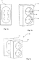
Figures 1a-c showing a wall mounted standardelectrical receptacle 10 according to prior art. Theelectrical receptacle 10 according to prior art is formed by wall-mountedjunction box 11 arranged to connect to an AC power supply grid, which exhibitsterminals 12 for receivingconductive connectors 21 of aplug 20 of a power cord 22 (shown inFigure 2c ) of a consumer, typically an electrical device. Theelectrical receptacle 10 further comprises areceptacle cover 13 which is fixed to thejunction box 11 and exhibits recesses 14 provided withholes 15 for receiving and accommodating theplug 20 and conductive connectors 21a and the arrange theplug 20 safely to theelectrical receptacle 10, as well as protecting the environment from electrically conductive parts. - Reference is now made to
Figures 2a-c showing a first embodiment of an adapter assembly for contactless transfer of electrical power according to a first embodiment of the present invention. According to the first embodiment of the adapter assembly according to the present invention the adapter assembly comprises afemale receptacle 110 formed by amain body 111 and provided withconductive connectors 112 at one end corresponding to the type ofelectrical receptacle 10 and at the other end is provided with a magnetic fastening means 113. Accordingly, thefemale receptacle 110 is adapted to be received in therecesses 14 of theelectrical receptacle 10 and provide a magnetic fastening means 113 for connection of amale plug 120 according to the present invention. Themale plug 120 of the adapter assembly according to the first embodiment of present invention is formed by amain body 121 which at one end is provided with femaleconductive connectors 122 adapted for receiving theconductive connectors 21 of aplug 20 and which at the other end is provided with a magnet magnetic fastening means 123 adapted for connection to thefemale receptacle 110 by magnetic force. Accordingly, withmale plugs 120 arranged to therelevant plugs 20 of apower cord 22 any kind ofpower cord 22 can be connected to theelectrical receptacle 10 by means of the adapter assembly according to the present invention. - The magnet fastening means 113 of the
female receptacle 110 is preferably recessed in themain body 111, while the magnetic fastening means 123 of themale plug 120 is preferably protruding from the end of themain body 121, such than when themale plug 120 is arranged to thefemale receptacle 110, the magnetic fastening means 113 of thefemale receptacle 110 is arranged to receive and accommodate the magnetic fastening means 123 of themale plug 120. The magnetic retaining force of the magnetic fastening means 113, 123 is preferably lower than the retaining force between theconductive connectors 112 andterminals 12 of thejunction box 11. In a preferable embodiment the magnetic fastening means 113, 123 exhibit a mainly circular shape. By this is achieved an adequate magnetic connection that will exhibit sufficient magnetic force holding themale plug 120 to thefemale receptacle 110. - According to the present invention the adapter assembly is further arranged for contactless transfer of electrical power between the
electrical receptacle 10 and themale plug 120 by that thefemale receptacle 110 andmale plug 120 are provided with magnetic or inductive means 131, 133, respectively, for contactless transfer of electrical power, which are connected with theconductive connectors 112 and femaleconductive connectors 122, respectively. - According to the present invention the
power cord 22 can also be manufactured with amale plug 120 as shown inFigure 2c and8 . - Reference is now made to
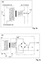
Figures 3a-c . Accordingly, thefemale receptacle 110 is provided withprimary side 131 of atransformer 132 and themale plug 120 is provided withsecondary side 133 of thetransformer 132, such that when thefemale receptacle 110 andmale plug 120 are connected together via the magnetic fastening means 113, 123 thetransformer 132 is capable of transferring power from thefemale receptacle 110 to themale plug 120 without physical contact between electrical power transferring parts. - By means of the
transformer 132 the adapter assembly will be capable of transforming supplied AC current/voltage (e.g. 110 V, 220 V, 400 V) at given frequency (e.g. 50-60 Hz) to desired output AC current/voltage (e.g. 110 V, 220 V, 400 V) at desired frequency (e.g. 50-60 Hz) adapted to the electrical device connected to the adapter assembly via apower cord 22. - According to a further embodiment of the adapter assembly according to the present invention, the
secondary side 133 of the transformer 130, i.e. themale plug 120 is further provided with arectifier unit 134 capable of rectifying supplied AC current/voltage (e.g. 110 V, 220 V, 400 V) to desired DC current/voltage, such as e.g. 3, 5, 9, 12, 24 etc. Accordingly, themale plug 120 then removes the need for transformer and/or rectifier in thepower cord 22 or electrical device. - The primary 131 and secondary 133 side of the transformer can be separated by air, iron-dust or iron. By use of iron dust or iron between the two
sides female receptacle 110 ormale plug 120, or in both. - Accordingly, the
male plug 120 can be arranged to theplug 20 of apower cord 22 until a supplier replaces thestandard plug 20 with a plug with the integratedmale plug 120 according to the present invention arranged for AC or DC according to the requirements of the electrical device. - Reference is now made to
Figure 4 showing a modified embodiment offemale receptacle 110 as described above. According to a modified embodiment of thefemale receptacle 110 according to the present invention themain body 111 is provided with at least onetrack 140, preferably two diametricallyopposite tracks 140, adapted for receiving aclip 150 designed to enter thetracks 140, By means of barbs on theclip 150 and corresponding recesses in thetracks 140 theclip 150 can engage thefemale receptacle 110 and thefemale receptacle 110 can in an easy manner be pulled out of engagement with or insertion into theelectric receptacle 10. - Reference is now made to
Figures 5a-b showing principle drawings of a second embodiment of afemale receptacle 110 of the adapter assembly according to the present invention. In the second embodiment the female receptacle(s) 110 is/are integrated in areceptacle cover 160 which is adapted to replace thestandard receptacle cover 20. In this embodiment thereceptacle cover 160 is preassembled with the female receptacle(s) 110, such that the female receptacle(s) 110 are fixed therein, e.g. by that they are casted in place or fixed by appropriate fastening means. By this embodiment thestandard receptacle cover 20 can be removed from thejunction box 11 and thereceptacle cover 160 with the integrated female receptacle(s) 110 can be connected to thejunction box 11 by insertion of theconductive connectors 112 in theterminals 12 of thejunction box 11 and fixation of thereceptacle cover 160 to thejunction box 11 by means ofstandard screw connections 161. - Reference is now made to
Figure 6 which is an example of astandard junction box 11 regardless of supplier withconductive connectors 16 for connection to respective conductors of an AC power supply grid andterminals 12 for connection thereto. The mentionedconductive connectors 16 can be omitted and the conductors of the AC power supply grid can be connected directly to thejunction box 11. Reference is also made toFigure 7 showing a principle drawing of a further embodiment of the adapter assembly according to the present invention where the above describedreceptacle cover 160 in addition to the female receptacle(s) 110 also has ajunction box 11 integrated, prearranged to thereceptacle cover 160 and female receptacle(s) 110. In such an embodiment thereceptacle cover 160 is preferably provided with throughholes 162 for accommodating fastening means 163, such as screws, enabling thereceptacle cover 160 with theintegrated junction box 11 and female receptacle(s) 110 to be fixed to awall 200. By this embodiment thereceptacle cover 160 according to the present invention will replace the need for ajunction box 11 as used in the above described embodiments. By this embodiment is achieved a solution where the conductors of the AC power supply grid can be connected directly to theintegrated junction box 11 or connected toconductive connectors 16 arranged thereto, and thejunction box 11 can be received in acavity 201 of awall 200 and thereceptacle cover 160 fixed to thewall 200 outside thecavity 201 as shown inFigure 7 or that thereceptacle cover 160 is arranged for being fixed to awall 200 surface for exterior arrangement. - According to a further embodiment of the present invention at least one safety device (not shown), in the form of e.g. a fuse, is arranged in either the
female receptacle 110 ormale plug 120, or in both. - Reference is now made to
Figures 8-9 showing principle drawings of a further embodiment of the adapter assembly according to the present invention.Figure 8 shows a femalemale plug 110 connected to apower cord 22, and a malefemale receptacle 120 connected to apower cord 22. When the femalemale plug 110 is magnetically connected to the malefemale receptacle 120, an extension cord is provided. The magnet fastening means 113 of thefemale receptacle 110 is as previously disclosed recessed in themain body 111, while the magnetic fastening means 123 of themale plug 120 is protruding from the end of themain body 121, such than when themale plug 120 is arranged to thefemale receptacle 110, the magnetic fastening means 113 of thefemale receptacle 110 is arranged to receive and accommodate the magnetic fastening means 123 of themale plug 120. In a preferable embodiment the magnetic fastening means 113, 123 exhibit a mainly circular shape. By this is achieved an adequate magnetic connection that will exhibit sufficient magnetic force holding themale plug 120 to thefemale receptacle 110. - According to the present invention the adapter assembly is arranged for contactless transfer of electrical power between the
electrical receptacle 110 and themale plug 120 by that thefemale receptacle 110 andmale plug 120 are provided with magnetic or inductive means 131, 133, respectively, for contactless transfer of electrical power, which are connected withrespective power cords 22. Thefemale receptacle 110 is, as shown inFigures 3a-c , provided withprimary side 131 of atransformer 132 and themale plug 120 is provided withsecondary side 133 of thetransformer 132, such that when thefemale receptacle 110 andmale plug 120 are connected together via the magnetic fastening means 113, 123 thetransformer 132 is capable of transferring power from thefemale receptacle 110 to themale plug 120 without physical contact between electrical power transferring parts. - Reference is now made to
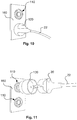
Figures 10-11 showing principle drawings of a further embodiment of the adapter assembly according to the present invention. In the shown embodiment thefemale receptacles 110 are integrated in areceptacle cover 160 as a junction box, which is mounted on or in a wall in the same manner as a typical electrical receptacle. In this embodiment thereceptacle cover box 160 is preassembled with thefemale receptacles 110, such that thefemale receptacles 110 are fixed therein, e.g. by that they are casted in place or fixed by appropriate fastening means. - In
figure 10 amale plug 120 connected to apower cord 22 is magnetically connected to a lowerfemale receptacle 110 integrated in thereceptacle cover box 160. Infigure 11 astandard plug 20 connected to apower cord 22 is inserted in thefemale receptacle 120, as previously disclosed, and thefemale receptacle 120 is magnetically connected to an upperfemale receptacle 110 integrated in thereceptacle cover 160 or box.
Claims (13)
- Adapter assembly for contactless transfer of electrical power, comprising a female receptacle (110) and a male plug (120), wherein the female receptacle (110) and the male plug (120) are provided with corresponding magnetic fastening means (113,123), respectively, for mutual connection by means of a magnetic force, wherein the female receptacle (110) and male plug (120) are provided with means for contactless transfer of electrical power in that the female receptacle (110) comprises a primary side (131) of a transformer (132) and the male plug (120) comprises a secondary side (133) of the transformer (132), such that when the female receptacle (110) and the male plug (120) are connected together via the magnetic fastening means (113,123), the transformer (132) is capable of transferring power from the female receptacle (110) to the male plug (120) without physical contact between power transferring parts, wherein- the female receptacle (110) comprises a main body (111) accommodating the primary side (131) of the transformer (132) and the magnetic fastening means (113), the magnetic fastening means (113) being recessed in the main body (111),
and- the male plug (120) comprises a main body (121) accommodating the secondary side (133) of the transformer (132) and the magnetic fastening means (123), the magnetic fastening means (123) protruding from the main body (121),
characterized in that- a front side of the main body (111) of the female receptacle (110) comprises two or more circular female recesses with magnetic fastening means (113) arranged for receiving and accommodating the magnetic fastening means (123) of the male plug (120), and- a front side of the main body (121) of the male plug (120) comprises two or more circular male protrusions with magnetic fastening means (123) adapted for arrangement to the magnet fastening means (113) of the female receptacle (110). - Adapter assembly according to claim 1, characterized in that the female receptacle (110) is connected to an AC power supply cord (22).
- Adapter assembly according to claim 1, characterized in that the male plug (120) is connected to an AC power supply cord (22).
- Adapter assembly according to claim 2 and 3, characterized in that the female receptacle (110) is a female connector and the male plug (120) is a male connector, for connection of two AC power supply cords (22).
- Adapter assembly according to claim 1, characterized in that two or more female receptacles (110) are provided in the main body, one above the other, wherein the main body is a receptacle cover or cover box (160) arranged for placement on a wall, and the female receptacles (110) are connected to an AC power supply.
- Adapter assembly to according to claim 1, characterized in that two or more female receptacles (110) and a junction box (11) are integrated in a receptacle cover (160) adapted for arrangement in connection with a cavity (201) of a wall (200).
- Adapter assembly according to claim 1, characterized in that the transformer (132) is arranged for transforming supplied AC current/voltage at a certain frequency to a desired output AC current/voltage of a desired frequency.
- Adapter assembly according to claim 1, characterized in that the transformer (132) is arranged for transforming supplied AC current/voltage to a desired DC current/voltage.
- Adapter assembly according to claim 8, characterized in that the female receptacle (110) and/or the male plug (120) is provided with a rectifier unit (134) connected at the secondary side (133) of the transformer (132).
- Adapter assembly according to claim 1, characterized in that the female receptacle (110) is provided with at least one track (140) adapted for receiving a clip (150) for easy handling of the female receptacle (110) in connection with arrangement to and/or from a standard electrical receptacle (10).
- Adapter assembly according to claim 1, characterized in that the female receptacle (110) is adapted for connection to an AC power supply at one end and the male plug (120) at the other end, the male plug (120) being adapted for connection to a power cord (22) at one end and to the female receptacle (110) at the other end, wherein the female receptacle (110) and male plug (120) are provided with said magnetic fastening means (113, 123), respectively.
- Female receptacle (110) for contactless transfer of electrical power, wherein the female receptacle (110) is provided with magnetic fastening means (113) and with means for contactless transfer of electrical power in that the female receptacle (110) comprises a primary side (131) of a transformer (132) for transferring power from the female receptacle (110) to a male plug (120) without physical contact between power transferring parts,- the female receptacle (110) comprises a main body (111) accommodating the primary side (131) of the transformer (132) and the magnetic fastening means (113), the magnetic fastening means (113) being recessed in the main body (111),
characterized in that a front side of the main body (111) comprises two or more circular female recesses with magnetic fastening means (113) arranged for receiving and accommodating magnetic fastening means (123) of the male plug (120). - Male plug (120) for contactless transfer of electrical power, wherein the male plug (120) is provided with magnetic fastening means (123) and with means for contactless transfer of electrical power in that the male plug (120) comprises a secondary side (133) of a transformer (132) for transferring power from the male plug (120) to a female receptacle (110) without physical contact between power transferring parts,- the male plug (120) comprises a main body (121) accommodating the secondary side (133) of the transformer (132) and the magnetic fastening means (123), the magnetic fastening means (123) protruding from the main body (121)
characterized in that a front side of the main body (121) comprises two or more circular male protrusions with magnetic fastening means (123) adapted for arrangement to magnet fastening means (113) of the female receptacle (110).
Applications Claiming Priority (2)
| Application Number | Priority Date | Filing Date | Title |
|---|---|---|---|
| NO20170364A NO342735B1 (en) | 2017-03-13 | 2017-03-13 | Adapter assembly for contactless transfer of electrical power |
| PCT/NO2018/050072 WO2018169409A1 (en) | 2017-03-13 | 2018-03-12 | Adapter assembly for contactless transfer of electrical power |
Publications (2)
| Publication Number | Publication Date |
|---|---|
| EP3596742A1 EP3596742A1 (en) | 2020-01-22 |
| EP3596742B1 true EP3596742B1 (en) | 2021-04-21 |
Family
ID=61832560
Family Applications (1)
| Application Number | Title | Priority Date | Filing Date |
|---|---|---|---|
| EP18714625.3A Active EP3596742B1 (en) | 2017-03-13 | 2018-03-12 | Adapter assembly for contactless transfer of electrical power |
Country Status (7)
| Country | Link |
|---|---|
| US (1) | US20200203895A1 (en) |
| EP (1) | EP3596742B1 (en) |
| JP (1) | JP7093373B2 (en) |
| CN (1) | CN110753981B (en) |
| DK (1) | DK3596742T3 (en) |
| NO (2) | NO342735B1 (en) |
| WO (1) | WO2018169409A1 (en) |
Families Citing this family (5)
| Publication number | Priority date | Publication date | Assignee | Title |
|---|---|---|---|---|
| JP7545829B2 (en) * | 2020-08-05 | 2024-09-05 | 株式会社安藤・間 | Wireless power supply device |
| US11411345B2 (en) * | 2020-11-04 | 2022-08-09 | Trenton Holway | Magnetic electrical outlet assembly |
| US12444880B2 (en) * | 2022-05-05 | 2025-10-14 | Tego Innovations, Inc. | Magnetic power distribution assembly |
| KR102449324B1 (en) * | 2022-05-10 | 2022-09-30 | 시춘근 | Buffer type ground transformer with electric power equipment installed |
| US12088247B2 (en) * | 2022-05-20 | 2024-09-10 | Inergy Holdings, Llc. | Modular photovoltaic power production system |
Citations (1)
| Publication number | Priority date | Publication date | Assignee | Title |
|---|---|---|---|---|
| US20140306546A1 (en) * | 2011-08-12 | 2014-10-16 | Koninklijke Philips N.V. | Universal voltage converter and inductive power coupling |
Family Cites Families (18)
| Publication number | Priority date | Publication date | Assignee | Title |
|---|---|---|---|---|
| US3363214A (en) | 1966-01-21 | 1968-01-09 | Charles T. Wright | Magnetic plug adapter |
| JPS55106984U (en) * | 1979-01-22 | 1980-07-26 | ||
| JPS5731818U (en) * | 1980-07-31 | 1982-02-19 | ||
| CN1178402A (en) * | 1996-08-09 | 1998-04-08 | 住友电装株式会社 | Charging Connectors for Electric Vehicles |
| JP3627421B2 (en) * | 1997-01-28 | 2005-03-09 | 松下電工株式会社 | Power connection device |
| JP4135299B2 (en) | 2000-06-27 | 2008-08-20 | 松下電工株式会社 | Non-contact power transmission device |
| US6736666B2 (en) * | 2002-03-28 | 2004-05-18 | Jeff Yu | Electrical plug having a pull ring |
| JP4128170B2 (en) | 2004-11-02 | 2008-07-30 | シャープ株式会社 | Power supply system and power supply service using the same |
| ITPI20050007A1 (en) * | 2005-01-20 | 2006-07-21 | Antonio Spinello | METHOD AND MECHANICAL AND ELECTRICAL CONNECTION DEVICE FOR A LAMP OR OTHER ELECTRICAL DEVICE WITH AN ELECTRIC POWER SOURCE |
| JP5255268B2 (en) * | 2007-12-25 | 2013-08-07 | パナソニック株式会社 | Contactless power supply adapter |
| CN102110936A (en) * | 2009-12-28 | 2011-06-29 | 鸿富锦精密工业(深圳)有限公司 | Connector |
| KR101064637B1 (en) * | 2010-07-21 | 2011-09-16 | 이권재 | Detachable Pluggable Adapter |
| KR20120129488A (en) * | 2011-05-20 | 2012-11-28 | (주)에스피에스 | Magnetic connecting device |
| US9083110B2 (en) | 2011-10-04 | 2015-07-14 | Todd Doobrow | Quick-disconnect power adapters |
| DE102011118564A1 (en) * | 2011-11-15 | 2013-05-16 | Grossenbacher System Ag | Contactless power supply and signal transmission through cladding element for building parts |
| US20130303024A1 (en) * | 2012-05-09 | 2013-11-14 | Kyo Nagase Rapp | Safety Electrical Interconnect |
| DE102012212254B3 (en) * | 2012-07-12 | 2014-01-09 | Fraunhofer-Gesellschaft zur Förderung der angewandten Forschung e.V. | Connector for cable-free signal transmission |
| KR101265584B1 (en) | 2012-12-07 | 2013-05-22 | 황윤홍 | Plug type concentric socket cover set, and setting method thereof |
-
2017
- 2017-03-13 NO NO20170364A patent/NO342735B1/en unknown
-
2018
- 2018-03-12 US US16/493,728 patent/US20200203895A1/en not_active Abandoned
- 2018-03-12 WO PCT/NO2018/050072 patent/WO2018169409A1/en not_active Ceased
- 2018-03-12 CN CN201880018788.5A patent/CN110753981B/en active Active
- 2018-03-12 DK DK18714625.3T patent/DK3596742T3/en active
- 2018-03-12 EP EP18714625.3A patent/EP3596742B1/en active Active
- 2018-03-12 NO NO20180350A patent/NO343885B1/en unknown
- 2018-03-12 JP JP2019572338A patent/JP7093373B2/en active Active
Patent Citations (1)
| Publication number | Priority date | Publication date | Assignee | Title |
|---|---|---|---|---|
| US20140306546A1 (en) * | 2011-08-12 | 2014-10-16 | Koninklijke Philips N.V. | Universal voltage converter and inductive power coupling |
Also Published As
| Publication number | Publication date |
|---|---|
| NO343885B1 (en) | 2019-07-01 |
| NO20170364A1 (en) | 2018-08-06 |
| CN110753981A (en) | 2020-02-04 |
| WO2018169409A1 (en) | 2018-09-20 |
| NO20180350A1 (en) | 2018-09-14 |
| JP2020516229A (en) | 2020-05-28 |
| CN110753981B (en) | 2022-04-12 |
| NO342735B1 (en) | 2018-08-06 |
| DK3596742T3 (en) | 2021-07-19 |
| US20200203895A1 (en) | 2020-06-25 |
| EP3596742A1 (en) | 2020-01-22 |
| JP7093373B2 (en) | 2022-06-29 |
Similar Documents
| Publication | Publication Date | Title |
|---|---|---|
| EP3596742B1 (en) | Adapter assembly for contactless transfer of electrical power | |
| CN104901080B (en) | Wall plug system for electric vehicle | |
| US9661768B2 (en) | Interchangeable electrically powered modules and receptacle therefor | |
| CA2715706C (en) | Worksurface power transfer | |
| KR20120080924A (en) | Electromagnetism electricity connection device | |
| CN104064916A (en) | Safety socket | |
| CA2922762A1 (en) | Apparatus for retaining plug in a receptacle | |
| KR101265584B1 (en) | Plug type concentric socket cover set, and setting method thereof | |
| WO2020186022A1 (en) | Wall plate system for data and/or power exchange | |
| US20140065886A1 (en) | Multi-Standard Socket Adaptor | |
| TWM626270U (en) | electrical signal switching device | |
| US20070141887A1 (en) | Waterproof power connector | |
| CN203250950U (en) | Safety socket | |
| US7465174B1 (en) | Coupling for connecting and disconnecting a plug and a socket | |
| TWI479756B (en) | Power adapter and electronic connector | |
| CN216903655U (en) | Electric signal switching device | |
| JP2832546B2 (en) | Electromagnetic outlet device | |
| TWI589074B (en) | Wireless electric connecting device | |
| CN207398515U (en) | Socket and plug | |
| CN208674446U (en) | A kind of novel secondary connector | |
| KR20190011842A (en) | Power connected apparatus including electric concent and electric plug | |
| WO2023065199A1 (en) | Electrical signal switching device | |
| US20130303024A1 (en) | Safety Electrical Interconnect | |
| JP2022115930A (en) | power conversion unit | |
| EP3989254A2 (en) | Cable switch with usb charger |
Legal Events
| Date | Code | Title | Description |
|---|---|---|---|
| STAA | Information on the status of an ep patent application or granted ep patent |
Free format text: STATUS: UNKNOWN |
|
| STAA | Information on the status of an ep patent application or granted ep patent |
Free format text: STATUS: THE INTERNATIONAL PUBLICATION HAS BEEN MADE |
|
| PUAI | Public reference made under article 153(3) epc to a published international application that has entered the european phase |
Free format text: ORIGINAL CODE: 0009012 |
|
| STAA | Information on the status of an ep patent application or granted ep patent |
Free format text: STATUS: REQUEST FOR EXAMINATION WAS MADE |
|
| 17P | Request for examination filed |
Effective date: 20191014 |
|
| AK | Designated contracting states |
Kind code of ref document: A1 Designated state(s): AL AT BE BG CH CY CZ DE DK EE ES FI FR GB GR HR HU IE IS IT LI LT LU LV MC MK MT NL NO PL PT RO RS SE SI SK SM TR |
|
| AX | Request for extension of the european patent |
Extension state: BA ME |
|
| DAV | Request for validation of the european patent (deleted) | ||
| DAX | Request for extension of the european patent (deleted) | ||
| GRAP | Despatch of communication of intention to grant a patent |
Free format text: ORIGINAL CODE: EPIDOSNIGR1 |
|
| STAA | Information on the status of an ep patent application or granted ep patent |
Free format text: STATUS: GRANT OF PATENT IS INTENDED |
|
| INTG | Intention to grant announced |
Effective date: 20201124 |
|
| GRAS | Grant fee paid |
Free format text: ORIGINAL CODE: EPIDOSNIGR3 |
|
| GRAA | (expected) grant |
Free format text: ORIGINAL CODE: 0009210 |
|
| STAA | Information on the status of an ep patent application or granted ep patent |
Free format text: STATUS: THE PATENT HAS BEEN GRANTED |
|
| AK | Designated contracting states |
Kind code of ref document: B1 Designated state(s): AL AT BE BG CH CY CZ DE DK EE ES FI FR GB GR HR HU IE IS IT LI LT LU LV MC MK MT NL NO PL PT RO RS SE SI SK SM TR |
|
| REG | Reference to a national code |
Ref country code: GB Ref legal event code: FG4D |
|
| REG | Reference to a national code |
Ref country code: CH Ref legal event code: EP |
|
| REG | Reference to a national code |
Ref country code: DE Ref legal event code: R096 Ref document number: 602018015870 Country of ref document: DE |
|
| REG | Reference to a national code |
Ref country code: IE Ref legal event code: FG4D |
|
| REG | Reference to a national code |
Ref country code: AT Ref legal event code: REF Ref document number: 1385509 Country of ref document: AT Kind code of ref document: T Effective date: 20210515 |
|
| REG | Reference to a national code |
Ref country code: DK Ref legal event code: T3 Effective date: 20210714 |
|
| REG | Reference to a national code |
Ref country code: SE Ref legal event code: TRGR |
|
| REG | Reference to a national code |
Ref country code: LT Ref legal event code: MG9D |
|
| REG | Reference to a national code |
Ref country code: AT Ref legal event code: MK05 Ref document number: 1385509 Country of ref document: AT Kind code of ref document: T Effective date: 20210421 |
|
| REG | Reference to a national code |
Ref country code: NL Ref legal event code: MP Effective date: 20210421 |
|
| PG25 | Lapsed in a contracting state [announced via postgrant information from national office to epo] |
Ref country code: FI Free format text: LAPSE BECAUSE OF FAILURE TO SUBMIT A TRANSLATION OF THE DESCRIPTION OR TO PAY THE FEE WITHIN THE PRESCRIBED TIME-LIMIT Effective date: 20210421 Ref country code: HR Free format text: LAPSE BECAUSE OF FAILURE TO SUBMIT A TRANSLATION OF THE DESCRIPTION OR TO PAY THE FEE WITHIN THE PRESCRIBED TIME-LIMIT Effective date: 20210421 Ref country code: LT Free format text: LAPSE BECAUSE OF FAILURE TO SUBMIT A TRANSLATION OF THE DESCRIPTION OR TO PAY THE FEE WITHIN THE PRESCRIBED TIME-LIMIT Effective date: 20210421 Ref country code: NL Free format text: LAPSE BECAUSE OF FAILURE TO SUBMIT A TRANSLATION OF THE DESCRIPTION OR TO PAY THE FEE WITHIN THE PRESCRIBED TIME-LIMIT Effective date: 20210421 Ref country code: BG Free format text: LAPSE BECAUSE OF FAILURE TO SUBMIT A TRANSLATION OF THE DESCRIPTION OR TO PAY THE FEE WITHIN THE PRESCRIBED TIME-LIMIT Effective date: 20210721 Ref country code: AT Free format text: LAPSE BECAUSE OF FAILURE TO SUBMIT A TRANSLATION OF THE DESCRIPTION OR TO PAY THE FEE WITHIN THE PRESCRIBED TIME-LIMIT Effective date: 20210421 |
|
| PG25 | Lapsed in a contracting state [announced via postgrant information from national office to epo] |
Ref country code: PT Free format text: LAPSE BECAUSE OF FAILURE TO SUBMIT A TRANSLATION OF THE DESCRIPTION OR TO PAY THE FEE WITHIN THE PRESCRIBED TIME-LIMIT Effective date: 20210823 Ref country code: RS Free format text: LAPSE BECAUSE OF FAILURE TO SUBMIT A TRANSLATION OF THE DESCRIPTION OR TO PAY THE FEE WITHIN THE PRESCRIBED TIME-LIMIT Effective date: 20210421 Ref country code: NO Free format text: LAPSE BECAUSE OF FAILURE TO SUBMIT A TRANSLATION OF THE DESCRIPTION OR TO PAY THE FEE WITHIN THE PRESCRIBED TIME-LIMIT Effective date: 20210721 Ref country code: LV Free format text: LAPSE BECAUSE OF FAILURE TO SUBMIT A TRANSLATION OF THE DESCRIPTION OR TO PAY THE FEE WITHIN THE PRESCRIBED TIME-LIMIT Effective date: 20210421 Ref country code: PL Free format text: LAPSE BECAUSE OF FAILURE TO SUBMIT A TRANSLATION OF THE DESCRIPTION OR TO PAY THE FEE WITHIN THE PRESCRIBED TIME-LIMIT Effective date: 20210421 Ref country code: IS Free format text: LAPSE BECAUSE OF FAILURE TO SUBMIT A TRANSLATION OF THE DESCRIPTION OR TO PAY THE FEE WITHIN THE PRESCRIBED TIME-LIMIT Effective date: 20210821 Ref country code: GR Free format text: LAPSE BECAUSE OF FAILURE TO SUBMIT A TRANSLATION OF THE DESCRIPTION OR TO PAY THE FEE WITHIN THE PRESCRIBED TIME-LIMIT Effective date: 20210722 |
|
| REG | Reference to a national code |
Ref country code: DE Ref legal event code: R097 Ref document number: 602018015870 Country of ref document: DE |
|
| PG25 | Lapsed in a contracting state [announced via postgrant information from national office to epo] |
Ref country code: CZ Free format text: LAPSE BECAUSE OF FAILURE TO SUBMIT A TRANSLATION OF THE DESCRIPTION OR TO PAY THE FEE WITHIN THE PRESCRIBED TIME-LIMIT Effective date: 20210421 Ref country code: RO Free format text: LAPSE BECAUSE OF FAILURE TO SUBMIT A TRANSLATION OF THE DESCRIPTION OR TO PAY THE FEE WITHIN THE PRESCRIBED TIME-LIMIT Effective date: 20210421 Ref country code: ES Free format text: LAPSE BECAUSE OF FAILURE TO SUBMIT A TRANSLATION OF THE DESCRIPTION OR TO PAY THE FEE WITHIN THE PRESCRIBED TIME-LIMIT Effective date: 20210421 Ref country code: EE Free format text: LAPSE BECAUSE OF FAILURE TO SUBMIT A TRANSLATION OF THE DESCRIPTION OR TO PAY THE FEE WITHIN THE PRESCRIBED TIME-LIMIT Effective date: 20210421 Ref country code: SK Free format text: LAPSE BECAUSE OF FAILURE TO SUBMIT A TRANSLATION OF THE DESCRIPTION OR TO PAY THE FEE WITHIN THE PRESCRIBED TIME-LIMIT Effective date: 20210421 Ref country code: SM Free format text: LAPSE BECAUSE OF FAILURE TO SUBMIT A TRANSLATION OF THE DESCRIPTION OR TO PAY THE FEE WITHIN THE PRESCRIBED TIME-LIMIT Effective date: 20210421 |
|
| PLBE | No opposition filed within time limit |
Free format text: ORIGINAL CODE: 0009261 |
|
| STAA | Information on the status of an ep patent application or granted ep patent |
Free format text: STATUS: NO OPPOSITION FILED WITHIN TIME LIMIT |
|
| 26N | No opposition filed |
Effective date: 20220124 |
|
| PG25 | Lapsed in a contracting state [announced via postgrant information from national office to epo] |
Ref country code: IS Free format text: LAPSE BECAUSE OF FAILURE TO SUBMIT A TRANSLATION OF THE DESCRIPTION OR TO PAY THE FEE WITHIN THE PRESCRIBED TIME-LIMIT Effective date: 20210821 Ref country code: AL Free format text: LAPSE BECAUSE OF FAILURE TO SUBMIT A TRANSLATION OF THE DESCRIPTION OR TO PAY THE FEE WITHIN THE PRESCRIBED TIME-LIMIT Effective date: 20210421 |
|
| PG25 | Lapsed in a contracting state [announced via postgrant information from national office to epo] |
Ref country code: IT Free format text: LAPSE BECAUSE OF FAILURE TO SUBMIT A TRANSLATION OF THE DESCRIPTION OR TO PAY THE FEE WITHIN THE PRESCRIBED TIME-LIMIT Effective date: 20210421 |
|
| PG25 | Lapsed in a contracting state [announced via postgrant information from national office to epo] |
Ref country code: MC Free format text: LAPSE BECAUSE OF FAILURE TO SUBMIT A TRANSLATION OF THE DESCRIPTION OR TO PAY THE FEE WITHIN THE PRESCRIBED TIME-LIMIT Effective date: 20210421 |
|
| REG | Reference to a national code |
Ref country code: CH Ref legal event code: PL |
|
| REG | Reference to a national code |
Ref country code: BE Ref legal event code: MM Effective date: 20220331 |
|
| PG25 | Lapsed in a contracting state [announced via postgrant information from national office to epo] |
Ref country code: LU Free format text: LAPSE BECAUSE OF NON-PAYMENT OF DUE FEES Effective date: 20220312 Ref country code: LI Free format text: LAPSE BECAUSE OF NON-PAYMENT OF DUE FEES Effective date: 20220331 Ref country code: IE Free format text: LAPSE BECAUSE OF NON-PAYMENT OF DUE FEES Effective date: 20220312 Ref country code: CH Free format text: LAPSE BECAUSE OF NON-PAYMENT OF DUE FEES Effective date: 20220331 |
|
| PGRI | Patent reinstated in contracting state [announced from national office to epo] |
Ref country code: LI Effective date: 20221206 Ref country code: CH Effective date: 20221206 |
|
| PG25 | Lapsed in a contracting state [announced via postgrant information from national office to epo] |
Ref country code: BE Free format text: LAPSE BECAUSE OF NON-PAYMENT OF DUE FEES Effective date: 20220331 |
|
| PG25 | Lapsed in a contracting state [announced via postgrant information from national office to epo] |
Ref country code: MK Free format text: LAPSE BECAUSE OF FAILURE TO SUBMIT A TRANSLATION OF THE DESCRIPTION OR TO PAY THE FEE WITHIN THE PRESCRIBED TIME-LIMIT Effective date: 20210421 Ref country code: CY Free format text: LAPSE BECAUSE OF FAILURE TO SUBMIT A TRANSLATION OF THE DESCRIPTION OR TO PAY THE FEE WITHIN THE PRESCRIBED TIME-LIMIT Effective date: 20210421 |
|
| PG25 | Lapsed in a contracting state [announced via postgrant information from national office to epo] |
Ref country code: HU Free format text: LAPSE BECAUSE OF FAILURE TO SUBMIT A TRANSLATION OF THE DESCRIPTION OR TO PAY THE FEE WITHIN THE PRESCRIBED TIME-LIMIT; INVALID AB INITIO Effective date: 20180312 |
|
| PG25 | Lapsed in a contracting state [announced via postgrant information from national office to epo] |
Ref country code: TR Free format text: LAPSE BECAUSE OF FAILURE TO SUBMIT A TRANSLATION OF THE DESCRIPTION OR TO PAY THE FEE WITHIN THE PRESCRIBED TIME-LIMIT Effective date: 20210421 |
|
| PG25 | Lapsed in a contracting state [announced via postgrant information from national office to epo] |
Ref country code: MT Free format text: LAPSE BECAUSE OF FAILURE TO SUBMIT A TRANSLATION OF THE DESCRIPTION OR TO PAY THE FEE WITHIN THE PRESCRIBED TIME-LIMIT Effective date: 20210421 |
|
| PGFP | Annual fee paid to national office [announced via postgrant information from national office to epo] |
Ref country code: CH Payment date: 20250401 Year of fee payment: 8 |
|
| REG | Reference to a national code |
Ref country code: CH Ref legal event code: U11 Free format text: ST27 STATUS EVENT CODE: U-0-0-U10-U11 (AS PROVIDED BY THE NATIONAL OFFICE) Effective date: 20260401 |
|
| PGFP | Annual fee paid to national office [announced via postgrant information from national office to epo] |
Ref country code: SE Payment date: 20260212 Year of fee payment: 9 |
|
| PGFP | Annual fee paid to national office [announced via postgrant information from national office to epo] |
Ref country code: GB Payment date: 20260213 Year of fee payment: 9 |
|
| PGFP | Annual fee paid to national office [announced via postgrant information from national office to epo] |
Ref country code: DE Payment date: 20260216 Year of fee payment: 9 Ref country code: DK Payment date: 20260220 Year of fee payment: 9 |
|
| PGFP | Annual fee paid to national office [announced via postgrant information from national office to epo] |
Ref country code: FR Payment date: 20260212 Year of fee payment: 9 |