EP3596637B1 - Medical device, programming device, wireless terminal, and medical system - Google Patents
Medical device, programming device, wireless terminal, and medical system Download PDFInfo
- Publication number
- EP3596637B1 EP3596637B1 EP18703578.7A EP18703578A EP3596637B1 EP 3596637 B1 EP3596637 B1 EP 3596637B1 EP 18703578 A EP18703578 A EP 18703578A EP 3596637 B1 EP3596637 B1 EP 3596637B1
- Authority
- EP
- European Patent Office
- Prior art keywords
- medical device
- unit
- container
- antenna
- wireless terminal
- Prior art date
- Legal status (The legal status is an assumption and is not a legal conclusion. Google has not performed a legal analysis and makes no representation as to the accuracy of the status listed.)
- Active
Links
Images




Classifications
-
- A—HUMAN NECESSITIES
- A61—MEDICAL OR VETERINARY SCIENCE; HYGIENE
- A61J—CONTAINERS SPECIALLY ADAPTED FOR MEDICAL OR PHARMACEUTICAL PURPOSES; DEVICES OR METHODS SPECIALLY ADAPTED FOR BRINGING PHARMACEUTICAL PRODUCTS INTO PARTICULAR PHYSICAL OR ADMINISTERING FORMS; DEVICES FOR ADMINISTERING FOOD OR MEDICINES ORALLY; BABY COMFORTERS; DEVICES FOR RECEIVING SPITTLE
- A61J1/00—Containers specially adapted for medical or pharmaceutical purposes
- A61J1/14—Details; Accessories therefor
-
- A—HUMAN NECESSITIES
- A61—MEDICAL OR VETERINARY SCIENCE; HYGIENE
- A61M—DEVICES FOR INTRODUCING MEDIA INTO, OR ONTO, THE BODY; DEVICES FOR TRANSDUCING BODY MEDIA OR FOR TAKING MEDIA FROM THE BODY; DEVICES FOR PRODUCING OR ENDING SLEEP OR STUPOR
- A61M5/00—Devices for bringing media into the body in a subcutaneous, intra-vascular or intramuscular way; Accessories therefor, e.g. filling or cleaning devices, arm-rests
- A61M5/14—Infusion devices, e.g. infusing by gravity; Blood infusion; Accessories therefor
- A61M5/142—Pressure infusion, e.g. using pumps
-
- A—HUMAN NECESSITIES
- A61—MEDICAL OR VETERINARY SCIENCE; HYGIENE
- A61M—DEVICES FOR INTRODUCING MEDIA INTO, OR ONTO, THE BODY; DEVICES FOR TRANSDUCING BODY MEDIA OR FOR TAKING MEDIA FROM THE BODY; DEVICES FOR PRODUCING OR ENDING SLEEP OR STUPOR
- A61M5/00—Devices for bringing media into the body in a subcutaneous, intra-vascular or intramuscular way; Accessories therefor, e.g. filling or cleaning devices, arm-rests
- A61M5/14—Infusion devices, e.g. infusing by gravity; Blood infusion; Accessories therefor
- A61M5/168—Means for controlling media flow to the body or for metering media to the body, e.g. drip meters, counters ; Monitoring media flow to the body
- A61M5/172—Means for controlling media flow to the body or for metering media to the body, e.g. drip meters, counters ; Monitoring media flow to the body electrical or electronic
-
- A—HUMAN NECESSITIES
- A61—MEDICAL OR VETERINARY SCIENCE; HYGIENE
- A61M—DEVICES FOR INTRODUCING MEDIA INTO, OR ONTO, THE BODY; DEVICES FOR TRANSDUCING BODY MEDIA OR FOR TAKING MEDIA FROM THE BODY; DEVICES FOR PRODUCING OR ENDING SLEEP OR STUPOR
- A61M5/00—Devices for bringing media into the body in a subcutaneous, intra-vascular or intramuscular way; Accessories therefor, e.g. filling or cleaning devices, arm-rests
- A61M5/178—Syringes
- A61M5/20—Automatic syringes, e.g. with automatically actuated piston rod, with automatic needle injection, filling automatically
-
- A—HUMAN NECESSITIES
- A61—MEDICAL OR VETERINARY SCIENCE; HYGIENE
- A61M—DEVICES FOR INTRODUCING MEDIA INTO, OR ONTO, THE BODY; DEVICES FOR TRANSDUCING BODY MEDIA OR FOR TAKING MEDIA FROM THE BODY; DEVICES FOR PRODUCING OR ENDING SLEEP OR STUPOR
- A61M5/00—Devices for bringing media into the body in a subcutaneous, intra-vascular or intramuscular way; Accessories therefor, e.g. filling or cleaning devices, arm-rests
- A61M5/178—Syringes
- A61M5/31—Details
- A61M5/315—Pistons; Piston-rods; Guiding, blocking or restricting the movement of the rod or piston; Appliances on the rod for facilitating dosing ; Dosing mechanisms
- A61M5/31565—Administration mechanisms, i.e. constructional features, modes of administering a dose
- A61M5/31566—Means improving security or handling thereof
- A61M5/31571—Means preventing accidental administration
-
- G—PHYSICS
- G06—COMPUTING OR CALCULATING; COUNTING
- G06K—GRAPHICAL DATA READING; PRESENTATION OF DATA; RECORD CARRIERS; HANDLING RECORD CARRIERS
- G06K19/00—Record carriers for use with machines and with at least a part designed to carry digital markings
- G06K19/06—Record carriers for use with machines and with at least a part designed to carry digital markings characterised by the kind of the digital marking, e.g. shape, nature, code
- G06K19/067—Record carriers with conductive marks, printed circuits or semiconductor circuit elements, e.g. credit or identity cards also with resonating or responding marks without active components
- G06K19/07—Record carriers with conductive marks, printed circuits or semiconductor circuit elements, e.g. credit or identity cards also with resonating or responding marks without active components with integrated circuit chips
- G06K19/077—Constructional details, e.g. mounting of circuits in the carrier
- G06K19/0772—Physical layout of the record carrier
- G06K19/0773—Physical layout of the record carrier the record carrier comprising means to protect itself against external heat sources
-
- G—PHYSICS
- G06—COMPUTING OR CALCULATING; COUNTING
- G06K—GRAPHICAL DATA READING; PRESENTATION OF DATA; RECORD CARRIERS; HANDLING RECORD CARRIERS
- G06K19/00—Record carriers for use with machines and with at least a part designed to carry digital markings
- G06K19/06—Record carriers for use with machines and with at least a part designed to carry digital markings characterised by the kind of the digital marking, e.g. shape, nature, code
- G06K19/067—Record carriers with conductive marks, printed circuits or semiconductor circuit elements, e.g. credit or identity cards also with resonating or responding marks without active components
- G06K19/07—Record carriers with conductive marks, printed circuits or semiconductor circuit elements, e.g. credit or identity cards also with resonating or responding marks without active components with integrated circuit chips
- G06K19/077—Constructional details, e.g. mounting of circuits in the carrier
- G06K19/07749—Constructional details, e.g. mounting of circuits in the carrier the record carrier being capable of non-contact communication, e.g. constructional details of the antenna of a non-contact smart card
- G06K19/07773—Antenna details
-
- G—PHYSICS
- G06—COMPUTING OR CALCULATING; COUNTING
- G06K—GRAPHICAL DATA READING; PRESENTATION OF DATA; RECORD CARRIERS; HANDLING RECORD CARRIERS
- G06K7/00—Methods or arrangements for sensing record carriers, e.g. for reading patterns
- G06K7/10—Methods or arrangements for sensing record carriers, e.g. for reading patterns by electromagnetic radiation, e.g. optical sensing; by corpuscular radiation
- G06K7/10009—Methods or arrangements for sensing record carriers, e.g. for reading patterns by electromagnetic radiation, e.g. optical sensing; by corpuscular radiation sensing by radiation using wavelengths larger than 0.1 mm, e.g. radio-waves or microwaves
- G06K7/10316—Methods or arrangements for sensing record carriers, e.g. for reading patterns by electromagnetic radiation, e.g. optical sensing; by corpuscular radiation sensing by radiation using wavelengths larger than 0.1 mm, e.g. radio-waves or microwaves using at least one antenna particularly designed for interrogating the wireless record carriers
- G06K7/10356—Methods or arrangements for sensing record carriers, e.g. for reading patterns by electromagnetic radiation, e.g. optical sensing; by corpuscular radiation sensing by radiation using wavelengths larger than 0.1 mm, e.g. radio-waves or microwaves using at least one antenna particularly designed for interrogating the wireless record carriers using a plurality of antennas, e.g. configurations including means to resolve interference between the plurality of antennas
-
- G—PHYSICS
- G16—INFORMATION AND COMMUNICATION TECHNOLOGY [ICT] SPECIALLY ADAPTED FOR SPECIFIC APPLICATION FIELDS
- G16H—HEALTHCARE INFORMATICS, i.e. INFORMATION AND COMMUNICATION TECHNOLOGY [ICT] SPECIALLY ADAPTED FOR THE HANDLING OR PROCESSING OF MEDICAL OR HEALTHCARE DATA
- G16H20/00—ICT specially adapted for therapies or health-improving plans, e.g. for handling prescriptions, for steering therapy or for monitoring patient compliance
- G16H20/10—ICT specially adapted for therapies or health-improving plans, e.g. for handling prescriptions, for steering therapy or for monitoring patient compliance relating to drugs or medications, e.g. for ensuring correct administration to patients
-
- G—PHYSICS
- G16—INFORMATION AND COMMUNICATION TECHNOLOGY [ICT] SPECIALLY ADAPTED FOR SPECIFIC APPLICATION FIELDS
- G16H—HEALTHCARE INFORMATICS, i.e. INFORMATION AND COMMUNICATION TECHNOLOGY [ICT] SPECIALLY ADAPTED FOR THE HANDLING OR PROCESSING OF MEDICAL OR HEALTHCARE DATA
- G16H20/00—ICT specially adapted for therapies or health-improving plans, e.g. for handling prescriptions, for steering therapy or for monitoring patient compliance
- G16H20/10—ICT specially adapted for therapies or health-improving plans, e.g. for handling prescriptions, for steering therapy or for monitoring patient compliance relating to drugs or medications, e.g. for ensuring correct administration to patients
- G16H20/13—ICT specially adapted for therapies or health-improving plans, e.g. for handling prescriptions, for steering therapy or for monitoring patient compliance relating to drugs or medications, e.g. for ensuring correct administration to patients delivered from dispensers
-
- G—PHYSICS
- G16—INFORMATION AND COMMUNICATION TECHNOLOGY [ICT] SPECIALLY ADAPTED FOR SPECIFIC APPLICATION FIELDS
- G16H—HEALTHCARE INFORMATICS, i.e. INFORMATION AND COMMUNICATION TECHNOLOGY [ICT] SPECIALLY ADAPTED FOR THE HANDLING OR PROCESSING OF MEDICAL OR HEALTHCARE DATA
- G16H40/00—ICT specially adapted for the management or administration of healthcare resources or facilities; ICT specially adapted for the management or operation of medical equipment or devices
- G16H40/40—ICT specially adapted for the management or administration of healthcare resources or facilities; ICT specially adapted for the management or operation of medical equipment or devices for the management of medical equipment or devices, e.g. scheduling maintenance or upgrades
-
- G—PHYSICS
- G16—INFORMATION AND COMMUNICATION TECHNOLOGY [ICT] SPECIALLY ADAPTED FOR SPECIFIC APPLICATION FIELDS
- G16H—HEALTHCARE INFORMATICS, i.e. INFORMATION AND COMMUNICATION TECHNOLOGY [ICT] SPECIALLY ADAPTED FOR THE HANDLING OR PROCESSING OF MEDICAL OR HEALTHCARE DATA
- G16H40/00—ICT specially adapted for the management or administration of healthcare resources or facilities; ICT specially adapted for the management or operation of medical equipment or devices
- G16H40/60—ICT specially adapted for the management or administration of healthcare resources or facilities; ICT specially adapted for the management or operation of medical equipment or devices for the operation of medical equipment or devices
- G16H40/63—ICT specially adapted for the management or administration of healthcare resources or facilities; ICT specially adapted for the management or operation of medical equipment or devices for the operation of medical equipment or devices for local operation
-
- G—PHYSICS
- G16—INFORMATION AND COMMUNICATION TECHNOLOGY [ICT] SPECIALLY ADAPTED FOR SPECIFIC APPLICATION FIELDS
- G16H—HEALTHCARE INFORMATICS, i.e. INFORMATION AND COMMUNICATION TECHNOLOGY [ICT] SPECIALLY ADAPTED FOR THE HANDLING OR PROCESSING OF MEDICAL OR HEALTHCARE DATA
- G16H40/00—ICT specially adapted for the management or administration of healthcare resources or facilities; ICT specially adapted for the management or operation of medical equipment or devices
- G16H40/60—ICT specially adapted for the management or administration of healthcare resources or facilities; ICT specially adapted for the management or operation of medical equipment or devices for the operation of medical equipment or devices
- G16H40/67—ICT specially adapted for the management or administration of healthcare resources or facilities; ICT specially adapted for the management or operation of medical equipment or devices for the operation of medical equipment or devices for remote operation
-
- A—HUMAN NECESSITIES
- A61—MEDICAL OR VETERINARY SCIENCE; HYGIENE
- A61J—CONTAINERS SPECIALLY ADAPTED FOR MEDICAL OR PHARMACEUTICAL PURPOSES; DEVICES OR METHODS SPECIALLY ADAPTED FOR BRINGING PHARMACEUTICAL PRODUCTS INTO PARTICULAR PHYSICAL OR ADMINISTERING FORMS; DEVICES FOR ADMINISTERING FOOD OR MEDICINES ORALLY; BABY COMFORTERS; DEVICES FOR RECEIVING SPITTLE
- A61J2205/00—General identification or selection means
- A61J2205/60—General identification or selection means using magnetic or electronic identifications, e.g. chips, RFID, electronic tags
-
- A—HUMAN NECESSITIES
- A61—MEDICAL OR VETERINARY SCIENCE; HYGIENE
- A61M—DEVICES FOR INTRODUCING MEDIA INTO, OR ONTO, THE BODY; DEVICES FOR TRANSDUCING BODY MEDIA OR FOR TAKING MEDIA FROM THE BODY; DEVICES FOR PRODUCING OR ENDING SLEEP OR STUPOR
- A61M2205/00—General characteristics of the apparatus
- A61M2205/35—Communication
- A61M2205/3576—Communication with non implanted data transmission devices, e.g. using external transmitter or receiver
-
- A—HUMAN NECESSITIES
- A61—MEDICAL OR VETERINARY SCIENCE; HYGIENE
- A61M—DEVICES FOR INTRODUCING MEDIA INTO, OR ONTO, THE BODY; DEVICES FOR TRANSDUCING BODY MEDIA OR FOR TAKING MEDIA FROM THE BODY; DEVICES FOR PRODUCING OR ENDING SLEEP OR STUPOR
- A61M2205/00—General characteristics of the apparatus
- A61M2205/35—Communication
- A61M2205/3576—Communication with non implanted data transmission devices, e.g. using external transmitter or receiver
- A61M2205/3584—Communication with non implanted data transmission devices, e.g. using external transmitter or receiver using modem, internet or Bluetooth®
-
- A—HUMAN NECESSITIES
- A61—MEDICAL OR VETERINARY SCIENCE; HYGIENE
- A61M—DEVICES FOR INTRODUCING MEDIA INTO, OR ONTO, THE BODY; DEVICES FOR TRANSDUCING BODY MEDIA OR FOR TAKING MEDIA FROM THE BODY; DEVICES FOR PRODUCING OR ENDING SLEEP OR STUPOR
- A61M2205/00—General characteristics of the apparatus
- A61M2205/35—Communication
- A61M2205/3576—Communication with non implanted data transmission devices, e.g. using external transmitter or receiver
- A61M2205/3592—Communication with non implanted data transmission devices, e.g. using external transmitter or receiver using telemetric means, e.g. radio or optical transmission
-
- A—HUMAN NECESSITIES
- A61—MEDICAL OR VETERINARY SCIENCE; HYGIENE
- A61M—DEVICES FOR INTRODUCING MEDIA INTO, OR ONTO, THE BODY; DEVICES FOR TRANSDUCING BODY MEDIA OR FOR TAKING MEDIA FROM THE BODY; DEVICES FOR PRODUCING OR ENDING SLEEP OR STUPOR
- A61M2205/00—General characteristics of the apparatus
- A61M2205/50—General characteristics of the apparatus with microprocessors or computers
-
- A—HUMAN NECESSITIES
- A61—MEDICAL OR VETERINARY SCIENCE; HYGIENE
- A61M—DEVICES FOR INTRODUCING MEDIA INTO, OR ONTO, THE BODY; DEVICES FOR TRANSDUCING BODY MEDIA OR FOR TAKING MEDIA FROM THE BODY; DEVICES FOR PRODUCING OR ENDING SLEEP OR STUPOR
- A61M2205/00—General characteristics of the apparatus
- A61M2205/50—General characteristics of the apparatus with microprocessors or computers
- A61M2205/502—User interfaces, e.g. screens or keyboards
-
- A—HUMAN NECESSITIES
- A61—MEDICAL OR VETERINARY SCIENCE; HYGIENE
- A61M—DEVICES FOR INTRODUCING MEDIA INTO, OR ONTO, THE BODY; DEVICES FOR TRANSDUCING BODY MEDIA OR FOR TAKING MEDIA FROM THE BODY; DEVICES FOR PRODUCING OR ENDING SLEEP OR STUPOR
- A61M2205/00—General characteristics of the apparatus
- A61M2205/50—General characteristics of the apparatus with microprocessors or computers
- A61M2205/52—General characteristics of the apparatus with microprocessors or computers with memories providing a history of measured variating parameters of apparatus or patient
-
- A—HUMAN NECESSITIES
- A61—MEDICAL OR VETERINARY SCIENCE; HYGIENE
- A61M—DEVICES FOR INTRODUCING MEDIA INTO, OR ONTO, THE BODY; DEVICES FOR TRANSDUCING BODY MEDIA OR FOR TAKING MEDIA FROM THE BODY; DEVICES FOR PRODUCING OR ENDING SLEEP OR STUPOR
- A61M5/00—Devices for bringing media into the body in a subcutaneous, intra-vascular or intramuscular way; Accessories therefor, e.g. filling or cleaning devices, arm-rests
- A61M5/14—Infusion devices, e.g. infusing by gravity; Blood infusion; Accessories therefor
Definitions
- the invention relates to a medical device, a programming device for a medical device, a wireless terminal for a medical device, and a medical system comprising a medical device and at least one of a programming device and a wireless terminal.
- Medical devices for example, injector devices, can be loaded with containers accommodating a pharmaceutical product.
- a pharmaceutical product For a prescribed usage of the medical device, it is necessary to ensure that a correct container is loaded and used in the medical device. Furthermore, it is necessary to ensure that a correct pharmaceutical product is used with the medical device. For example, it has to be ensured that the medical device is not used with a pharmaceutical product that has expired.
- EP 2 249 275 A1 relates to management of information relating to medical fluids, containers therefor, and medical fluid administration devices for administering such medical fluids to patients.
- Data tags e.g., RFID tag
- RFID tag are associated with containers and can be electromagnetically read from and/or written to using an electromagnetic device that is associated with a medical fluid administration device.
- the invention is directed at the object of providing an improved medical device which prevents erroneous usage of the medical device.
- the medical device comprises a container receiver unit configured to receive and hold a container, wherein the container accommodates a pharmaceutical product and comprises a first communication tag configured to store information regarding the pharmaceutical product, a reader unit configured to wirelessly read the information from the first communication tag, and a control unit configured to control the medical device based on the information read from the first communication tag.
- the medical device may be any kind of medical equipment that is adapted to be loaded with a container or cartridge that accommodates a pharmaceutical product.
- the medical device is an injector device that is configured to eject a skin needle and dispense via the ejected skin needle a pharmaceutical product accommodated in a container through the skin of a human or animal body.
- the term "pharmaceutical product” is meant to encompass any medicament-containing flowable drug configured to be passed through a hollow needle of the injector device in a controlled manner, such as a liquid, solution, gel or fine suspension.
- the container receiver unit may be any kind of mechanical holding unit that is adapted to receive and hold in a fixed manner the container.
- the container receiver unit may be a container receptacle having a door or a shutter, or a container receptacle that can moved by means of a spring at least partly out of the medical device.
- the first communication tag may be any kind of storage means that is adapted to store data that can be wirelessly read by the reader unit.
- the first communication tag is a near-field communication (NFC) tag and the reader unit is an NFC initiator device.
- the NFC tag may be any of the NFC types defined by the NFC Forum.
- the NFC tag may be read-only and can only be encoded by the manufacturer of the container. Alternatively, the NFC tag may also have reading and writing capabilities.
- the devices may operate in an NFC passive mode in which the initiator device provides a carrier field and the target device, i.e., the first communication tag, answers by modulating the carrier field.
- the first communication tag may be a barcode or an ultra-high frequency (UHF) radiofrequency identification (RFID) tag.
- UHF ultra-high frequency
- RFID radiofrequency identification
- the control unit may be any kind of control device, for example, a microcontroller, which is configured to control the medical device based on the information read from the first communication tag. For example, the control unit may prevent the medical device from dispensing the pharmaceutical product accommodated in the container in case the information read from the first communication tag indicates that the pharmaceutical product has expired.
- the medical device comprises an opening or a transparent window allowing to at least partially see from the outside the container inserted into the container receiver unit, wherein the reader unit comprises a first antenna unit, and the container inserted into the container receiver unit is located between (i) the opening or the transparent window and (ii) the first antenna unit.
- the opening or transparent window may be provided at the housing of the medical device, preferably, in proximity to the location where the container can be inserted into the container receiver unit.
- the arrangement of the container between the opening or transparent window and the reader unit provides a double function of allowing a user of the medical device to view the container from the outside (for example, to read a printed label provided on the container), and ensuring that the reader unit can wirelessly read the information regarding the pharmaceutical product from the first communication tag.
- a double check of the container by the medical device and the user of the medical device is enabled.
- the container receiver unit is configured to allow a user of the medical device to rotate the container around its middle axis.
- the container may be held in such a manner in the container receiver unit that only the distal and proximal ends of the container are supported in the container receiver unit.
- the first antenna unit may only partially surround the container inserted into the container receiver unit.
- the first antenna unit and the opening or transparent window completely surround the container, i.e., the side area of a substantially cylindrically shaped container.
- a cross section area of the first antenna unit surrounds between 50% and 30% of a cross section area of the container.
- the first antenna unit may comprise a first antenna part extending along a first plane and a second antenna part extending along a second plane.
- the first antenna part and the second antenna part may be separate antennas.
- Each of the first antenna part and the second antenna part may have a substantially square, circled, looped, or rectangular shape.
- each of the first antenna part and the second antenna part may be at least one of a wire loop antenna and a stamp antenna.
- Each of the first antenna part and the second antenna part may also be any of the antenna classes defined in ISO/IEC 14443.
- the first antenna part and the second antenna part may also be parts of one flexible antenna.
- the first plane and the second plane cross each other with an angle in the range from 90° to 120°, wherein the angle faces the container inserted into the container receiver unit.
- the medical device comprises a second communication tag.
- the second communication tag is configured to wirelessly receive and store information regarding debugging of the medical device.
- the second communication tag is readable by the reader unit, may be readable also by an external device, and is writeable by an external device. Similar to the first communication tag, the second communication tag may be an NFC tag.
- the second communication tag may be operated in a passive mode or an active mode. To maintain the sterility of a packaged medical device, the second communication tag allows programming the medical device from the outside without having to open the medical device. For example, by sending data to the second communication tag, it is possible to externally set run-time parameters of the medical device, e.g., an ejection speed for ejecting a skin needle from an injector device.
- the reader unit comprises a second antenna unit configured to read the information stored in the second communication tag
- the control unit is configured to control the medical device based on the information read from the second communication tag.
- a programming device that is configured to wirelessly write data in the second communication tag
- a pharmacist may set certain parameters of the medical device at the point of sale, based on the prescription of the specific patient, but without requiring him/her to open the medical device and lose its sterility.
- the second communication tag may also be used for contactless transfer of information to the medical device for debua and setup purposes.
- the information stored in the second communication tag is used to enter the medical device into specific debug modes, the debug mode being a mode for calibrating sensors (e.g., a skin sensor) in the medical device or a mode for checking the angular detection ability of the first communication tag by the reader unit.
- the debug mode being a mode for calibrating sensors (e.g., a skin sensor) in the medical device or a mode for checking the angular detection ability of the first communication tag by the reader unit.
- control unit may be configured to control the medical device based on the information read from the second communication tag and the information read from the first communication tag.
- the medical device further comprises a switch unit connected to the reader unit, wherein the reader unit comprises three antennas, and the switch unit is configured to consecutively switch signals received from the three antennas to the control unit.
- a first antenna and a second antenna are used for reading the information stored in the first communication tag.
- a third antenna is used for reading the information stored in the third communication tag.
- the medical device further comprises a communication unit configured to wirelessly communicate with a wireless terminal, wherein the communication unit is further configured to send, in real-time, information regarding the status of the medical device to the wireless terminal, send debugging data concerning the medical device to the wireless terminal, and/or send data regarding usage of the medical device to the wireless terminal.
- the communication unit may be a Bluetooth transceiver unit that is configured to communicate with a corresponding Bluetooth transceiver unit in a wireless terminal, e.g., a smartphone running a specific software or app that is programmed to process the received data.
- the wireless terminal receiving the data from the medical device can enable an enhanced functionality of the medical device, such as healthcare monitoring, monitoring of usage of the medical device, monitoring of adherence of the patient, tracking of past medication, ordering of new medication via the Internet, history look-up, dosage information check, providing guidance to the user on use-steps, and/or trouble-shooting.
- the medical device and the wireless terminal may enter into a training mode in which the wireless terminal can track in real time the status of the medical device and show the user next steps to be executed in the form of animations, videos, or written explanations.
- the medical device and the wireless terminal may also enter into a debug mode in which a control software running on a processor in the medical device can be debugged using the connection between the medical device and the wireless terminal, and a corresponding app running on the wireless terminal to view internal variables of the medical device.
- the invention further concerns a programming device comprising a sending unit configured to send information regarding debugging of a medical device.
- the programming device sends the information wirelessly to the medical device.
- the programming device may be any kind of computing device that is adapted to receive, process, and send data.
- the programming device comprises an NFC initiator device which is configured to wirelessly write data in the second communication tag, which is located in the medical device.
- the initiator device and the target device i.e., the second communication tag
- the initiator device and the target device operate in an active mode.
- the programming device may further comprise a user interface, for example, a touch-sensitive screen displaying an app, which is configured to enter the information regarding at least one of prescription of a pharmaceutical product, setup of the medical device, debugging of the medical device, and calibration of the medical device.
- the programming device may further comprise a processing device that processes the data received from the second communication tag.
- the invention further concerns a wireless terminal comprising a communication unit configured to wirelessly communicate with the medical device, wherein the communication unit is further configured to receive, in real-time, information regarding the status of the medical device from the medical device, receive debugging data concerning the medical device from the medical device, and/or receive data regarding usage of the medical device from the medical device.
- the wireless terminal may be any kind of wireless communication terminal, for example, a smartphone.
- the communication unit may, for example, comprise a Bluetooth transceiver unit that is configured to communicate with a corresponding Bluetooth transceiver unit in the medical device.
- Other wireless communication standards like Wi-Fi, LTE, WLAN, WiMAX or ZigBee may also be used for the communication between the medical device and the wireless terminal.
- the wireless terminal may be configured to communicate via the Internet with an external web server that stores data related to the medical device and/or the user of the medical device.
- the wireless terminal further comprises a processing unit configured to process the data received from the medical device.
- the processing unit may receive, in real-time, information regarding the status of the medical device from the medical device, and may control a display unit in the wireless terminal to display animations, videos, and/or written explanations regarding next steps necessary to be executed by the user of the medical device.
- the invention further concerns a medical system comprising a medical device, and at least one of a programming device and a wireless terminal.
- Fig. 1 schematically shows a first medical device 100 according to a first embodiment.
- the medical device 100 comprises a container receiver unit 110 configured to receive and hold a container 120, a reader unit 140 comprising a first antenna 142 and a second antenna 144, a control unit 150, an ignition button 170, and a switch unit 185 connected to the reader unit 140.
- the components of the medical device 100 are provided in a housing 160.
- the medical device 100 comprises an opening 165.
- a transparent window may be provided at one side of the housing 160.
- the opening 165 is provided at a location that is proximal to the container receiver unit 110 so that a container 120 inserted in the container receiver unit 110 can be seen from the outside by a user when looking through the opening 165 into the medical device 100.
- the container 120 is adapted to accommodate a pharmaceutical product 125 and comprises a label 135 which is fixed around the outer circumference of the container 120 and which presents information about the pharmaceutical product 125 accommodated in the container 120 (e.g., product name, batch number, expiry date, etc.). Furthermore, the container 120 comprises a first NFC tag 130 which is fixed around the outer circumference of the container 120 and which is configured to store information regarding the pharmaceutical product 125 (e.g., product name, batch number, expiry date, etc.).
- the opening or transparent window 165 may have any shape and size that allows a user to see the label 135, however, does not allow the container 120 to fall out of the medical device 100.
- Fig. 2 shows an example of a container 120 with a printed label 135 which is fixed around the outer circumference of the container 120.
- the container 120 has a substantially cylindrical shape.
- the dashed line in Fig. 2 indicates the middle axis of the container 120.
- the container 120 comprises a sealed dispensing port 122 through which a medical drug stored in the container 120 may be dispensed in case a piston provided in an axially movable manner in the container 120 pushes the medical drug (not shown in Fig. 2 ) through the dispensing port 122.
- Fig. 3 shows an exemplary label 135 in an un-affixed and an unwound form.
- the label 135 comprises an NFC tag 130 which is integrated in the sheet of the label 135 so that it is not visible from the outside (not shown in Fig. 3 ).
- an exemplary NFC tag 130 is shown in Fig. 4 in a form detached from the label 135.
- the NFC tag 130 comprises a memory 131 in which information regarding the pharmaceutical product 125 is stored, and an RFID antenna 132.
- the NFC tag 130 is designed to fit around the outer surface of a 3 ml container 120.
- the NFC tag 130 is designed to be able to be read from all 360° angles when affixed to the container 120.
- the opening 165 provided in the housing 160 has such a size, and the container 120 inserted in the container receiver unit 110 is located in such proximity to the opening 165 that a user can touch with his fingers through the opening 165 the container 120.
- the container receiver unit 110 may be structured such that it only supports the container 120 at is distal end and its proximal end so that it may be rotated within the container receiver unit 110 around its middle axis (see Fig. 2 ).
- the first antenna 142 and the second antenna 144 enable reading of the information stored in the first NFC tag 130.
- the opening 165 may be included in a door or a shutter, or any other access mechanism that may be used for inserting the container 120 into the medical device 100, i.e., into the container receiver unit 110.
- the reader unit 140 is configured to wirelessly read the information from the first NFC tag 130
- the control unit 150 is configured to control the medical device 100 based on the information read from the first NFC tag 130. For example, when the first NFC tag 130 stores data regarding the expiry date of the pharmaceutical product 125, and the reader unit 140 reads this information from the first NFC tag 130, the control unit 150 may process the received information and control the medical device 100 such that a dispensing of the pharmaceutical product 125, which has expired, is not possible. For this, the control unit 150 may control the medical device 100 such that when a user presses the ignition button 170, the medical device 100 does not dispense the pharmaceutical product 125 from the medical device 100.
- the container receiver unit 110 is provided between the opening 165 and the reader unit 130.
- the opening 165 and the reader unit 140 are provided directly at the container receiver unit 110 holding the container 120.
- the switch unit 185 is adapted to switch the input signals received via each of the first antenna 142 and the second antenna 144 in a rotational manner to the control unit 150. For this, the switch unit 185 is controlled by the control unit 150. Accordingly, the data stored in the first NFC tag 130 can be read via the first antenna 142 and the second antenna 144.
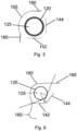
- Fig. 5 schematically shows a partial cross section of a second medical device.
- the second medical device corresponds to the first medical device 100 shown in Fig. 1 so that the same reference numbers concern the same elements.
- the second medical device partly shown in Fig. 5 comprises at the housing 160 a transparent window 165 instead of the opening.
- similar technical effects may also be achieved with an opening.
- Fig. 5 shows as an exemplary embodiment illustrating how the first antenna 142 and the second antenna 144 may be arranged with regard to the container 120 so that the first NFC tag 130 (not shown in Fig. 5 ) can always be read via at least one the first antenna 142 and the second antenna 144, and the label 135 (not shown in Fig. 6 ) can be seen from the outside through the transparent window 165.
- the first antenna 142 extends along a first plane
- the second antenna 144 extends along a second plane.
- Each of the first antenna 142 and the second antenna 144 has a substantially square shape.
- the first antenna 142 has a length that is smaller than the diameter of the container 120.
- the second antenna 144 has a length that is smaller than the diameter of the container 120.
- the first plane and the second plane are substantially perpendicular to each other.
- the first antenna 142 together with the second antenna 144 only partially surround the container 120.
- a cross section area of the first antenna 142 together with the second antenna 144 surrounds between 50% and 30% of a cross section area of the container 120.
- either the first antenna 142 or the second antenna 144 can read the data stored in first NFC tag 130, and the user can read the label 135 from the outside through the transparent window 165.
- at any given angle at least one of the first antenna 142 or the second antenna 144 has sufficient overlap with the container 120.
- Fig. 6 schematically shows a partial cross section of a third medical device.
- the third medical device corresponds to the first medical device 100 shown in Fig. 1 so that the same reference numbers concern the same elements.
- the third medical device partly shown in Fig. 6 comprises a transparent window 165 instead of the opening.
- similar technical effects may also be achieved with an opening.
- the transparent window 165 has a larger size. Specifically, as is indicated by the dashed lines in Fig. 6 , a larger area of sight through the transparent window 165, which is provided in the housing 160, is foreseen.
- the first antenna 142 extends along a first plane
- the second antenna 144 extends along a second plane.
- each of the first antenna 142 and the second antenna 144 has a substantially square shape.
- the first axis and the second axis cross each other with an angle ⁇ , which is larger than 90°.
- the angle ⁇ is in the range from 90° to 120°.
- the first antenna 142 and the second antenna 144 are V-shaped.
- each of the first antenna 142 and the second antenna 144 has a length that approximately corresponds to the diameter of the container 120.
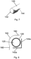
- Fig. 7 schematically shows a partial perspective view of a fourth medical device.
- the fourth medical device corresponds to the first medical device 100 shown in Fig. 1 and the third medical device shown in Fig. 6 so that the same reference numbers concern the same elements.
- the plane areas of the first antenna 142 and the second antenna 144 can be seen.
- each of the first antenna 142 and the second antenna 144 shown in Fig. 7 has a substantially rectangular shape
- each of the first antenna 142 and the second antenna 144 may also have another shape, e.g., a substantially square, circled, or looped shape.
- Fig. 8 schematically shows a partial perspective view of a fourth medical device.
- the medical device shown in Fig. 8 may be the medical device 100 shown in Fig. 1 .
- the medical device shown in Fig. 8 is similar to the medical device shown in Fig. 5 , however, differs from the medical device shown in Fig. 5 in that only one flexible antenna having a first antenna part 142a and a second antenna part 144a is provided.
- the flexible antenna may consist of a flexible substrate onto which an antenna circuit is printed.
- the medical device shown in Fig. 8 has a substantially rectangular shape and is bent with an angle of 90°. However, other shapes and other bending angles are possible, e.g., the shapes and angles described with regard to Figs. 1 and 5 to 7 .
- Fig. 9 schematically shows a medical system comprising a medical device 100a and a programming device 200 according to a second embodiment.
- the medical device 100a shown in Fig. 9 is based on the medical device 100 shown in Fig. 1 so that the same reference numbers concern the same elements and any repeated explanation thereof is omitted.
- the medical device 100a according to the second embodiment shown in Fig. 9 comprises a second NFC tag 180, and the receiver unit 140 comprises a third antenna 146.
- the second NFC tag 180 is provided in a fixed manner in the medical device 100a.
- the second NFC tag 180 is provided at a location in proximity to the third antenna 146 so that the data stored in the second NFC tag 130 can be read via the third antenna 146.
- the control unit 150 can control the medical device 100a.
- the control unit 150 can obtain and process the information from both the first NFC tag 130 and the second NFC tag 180 before allowing the medical device 100a to dispense the pharmaceutical product 125 from the container 120.
- the second NFC tag 180 is configured to wirelessly receive and store information regarding at least one of prescription of the pharmaceutical product 125, setup of the medical device 100a, debugging of the medical device 100a, and calibration of the medical device 100a.
- the control unit 150 may control the medical device 100a, i.e., components of the medical device 100a.
- the switch unit 185 is adapted to switch the input signals received via each of the first antenna 142, the second antenna 144, and the third antenna 146 in a rotational manner to the control unit 150.
- the switch unit 185 is controlled by the control unit 150. Accordingly, the data stored in the first NFC tag 130 can be read via the first antenna 142 and the second antenna 144, and the data stored in the second NFC tag 180 can be read via the third antenna 146.
- the medical system 100a shown in Fig. 9 further comprises a programming device 200.
- the programming device 200 comprises a sending unit 210 and a user interface 220.
- the sending unit 210 is configured to send information regarding debugging of the medical device 100a, and may be in addition be configured to send information regarding at least one of prescription of pharmaceutical product 125, setup of the medical device 100a, and calibration of the medical device 100a to the medical device 100a. Specifically, the sending unit 210 is configured to send any of this information to the second NFC tag 180, which stores the received information in its memory.
- the sending unit 220 may, for example, be an NFC initiator device.
- the sending unit 220 and the second NFC tag 180 may operate in a passive mode. However, the sending unit 220 and the second NFC tag 180 may also operate in an active mode.
- the programming device 200 additionally comprises a processing unit (not shown in Fig. 9 ) configured to process the data received from the second NFC tag 180.
- the user interface 220 is configured to enter the information regarding at least one of prescription of a pharmaceutical product 125, setup of the medical device 100a, debugging of the medical device 100a and calibration of the medical device 100a into the programming device 200. Accordingly, a pharmacist may use the programming device 200 to set certain parameters of the medical device 100a at the point of sale without requiring him/her to open the medical device 100a and lose its sterility.
- the programming device 200 may be used for transferring information to the second NFC tag 180, which may be used by the control unit 150 to enter the medical device 100 into specific debug modes, such as a mode for calibrating sensors in the medical device 100a (e.g., a skin sensor in an injector device), a mode for checking the angular detection ability of the first NFC tag 130 by the reader unit 140, and a system setup mode to modify parameters such as needle injection speed and/or skin sensor detection threshold when the medical device 100a is implemented as an injector device, the system setup mode not falling under the scope of protection of the claims.
- specific debug modes such as a mode for calibrating sensors in the medical device 100a (e.g., a skin sensor in an injector device), a mode for checking the angular detection ability of the first NFC tag 130 by the reader unit 140, and a system setup mode to modify parameters such as needle injection speed and/or skin sensor detection threshold when the medical device 100a is implemented as an injector device, the system setup mode not falling under the scope of protection of the
- Data received from the second NFC tag 180 operating in an active mode and processed by the processing unit may also be displayed in a display of the user interface 220.
- Fig. 10 schematically shows an example of a receiving unit 142, 144, 146 with a switch unit 185.
- the receiving unit 142, 144, 146 and the switch unit 185 may be the units shown in Fig. 9 .
- the same reference numbers concern the same elements.
- an RFID reader/writer integrated circuit 190 is connected to the switch unit 185.
- the switch unit 185 is adapted to split four input signals into four channels, as indicated by the four arrows originating from switch unit 185.
- up to four antennas can be connected to the switch unit 185.
- the switch unit 185 can read each of the first antenna 142, the second antenna 144, and the third antenna 146 in a rotational manner. Accordingly, it can be ensured that at least one of the first antenna 142 and the second antenna 144 detects the first NFC tag 130 (not shown in Fig. 10 ) provided on the container 120.
- Fig. 11 schematically shows a medical system comprising a medical device 100b and a wireless terminal 300 according to a third embodiment.
- the medical device 100b according to the third embodiment shown in Fig. 11 is based on the medical device 100 according to the first embodiment shown in Fig. 1 .
- the third embodiment according to Fig. 11 may be combined with the second embodiment according to Fig. 9 , i.e., the elements additionally shown in the medical device 100a of Fig. 9 may be included in the medical device 100b shown in Fig. 11 .
- the programming device 200 shown in Fig. 9 may additionally be provided in the medical system of the third embodiment according to Fig. 11 .
- the medical device 100b according to the third embodiment shown in Fig. 11 differs from the medical device 100 according to the first embodiment shown in Fig. 1 in that a communication unit 195 is additionally provided in the medical device 100b.
- the communication unit 195 is a Bluetooth transceiver unit which is configured to wirelessly communicate with a wireless terminal 300.
- the wireless terminal 300 comprises a first communication unit 310 implemented as a Bluetooth transceiver unit which is configured to wirelessly communicate with the communication unit 195 in the medical device 100b. Furthermore, the wireless terminal 300 comprises a processing unit 320, a display unit 330, and a second communication unit 340.
- a first communication unit 310 implemented as a Bluetooth transceiver unit which is configured to wirelessly communicate with the communication unit 195 in the medical device 100b.
- the wireless terminal 300 comprises a processing unit 320, a display unit 330, and a second communication unit 340.
- the communication unit 195 of the medical device 100b is connected to the control unit 150.
- the control unit 150 controls the sending of data from the communication unit 195 via an air interface to the first communication unit 310.
- the control unit 150 controls the communication unit 195 to send to the first communication unit 320 in the wireless terminal 300, in real-time, information regarding the status of the medical device 100b.
- the communication unit 195 may also or additionally send debugging data concerning the medical device 100b, and/or data regarding usage of the medical device 100b to the first communication unit 320.
- the processing unit 320 in the wireless terminal 300 is configured to process the data received from the medical device 100b. For example, the processing unit 320 receives, in real-time, information regarding the status of the medical device 100b and controls the display unit 330 to display animations, videos, and/or written explanations regarding next steps necessary to be executed by the user of the medical device 100b.
- the second communication unit 340 is configured to setup a connection to the Internet.
- the second communication unit 340 is realized as a wireless local area network (WLAN) module.
- the second communication unit 340 may also be realized as a long-term evolution (LTE) module or any other wireless module that is configured to setup a connection to the Internet.
- LTE long-term evolution
- the WLAN module 340 is configured to setup a connection to the Internet and communicate with a web server 500.
- the web server 500 may, for example, belong to a pharmaceutical company or a pharmacist so that a new container 120 can be ordered by the wireless terminal 300 in case the information received from the medical device 100b and/or the information stored in the wireless terminal 300 indicates that the user of the medical device 100b requires a new container 120. Moreover, the web server 500 may store data regarding update and/or debugging of the medical device 100b. The information received from the medical device 100b may be sent to the web server 500 in order to compare the information with data from other medical devices.
Landscapes
- Health & Medical Sciences (AREA)
- Engineering & Computer Science (AREA)
- General Health & Medical Sciences (AREA)
- Biomedical Technology (AREA)
- Public Health (AREA)
- Epidemiology (AREA)
- Medical Informatics (AREA)
- Primary Health Care (AREA)
- Business, Economics & Management (AREA)
- General Business, Economics & Management (AREA)
- Physics & Mathematics (AREA)
- Theoretical Computer Science (AREA)
- Toxicology (AREA)
- General Physics & Mathematics (AREA)
- Veterinary Medicine (AREA)
- Animal Behavior & Ethology (AREA)
- Life Sciences & Earth Sciences (AREA)
- Computer Networks & Wireless Communication (AREA)
- Heart & Thoracic Surgery (AREA)
- Hematology (AREA)
- Vascular Medicine (AREA)
- Anesthesiology (AREA)
- Chemical & Material Sciences (AREA)
- Medicinal Chemistry (AREA)
- Bioinformatics & Cheminformatics (AREA)
- Electromagnetism (AREA)
- Artificial Intelligence (AREA)
- Computer Vision & Pattern Recognition (AREA)
- Microelectronics & Electronic Packaging (AREA)
- Computer Hardware Design (AREA)
- Pharmacology & Pharmacy (AREA)
- Medical Preparation Storing Or Oral Administration Devices (AREA)
- Infusion, Injection, And Reservoir Apparatuses (AREA)
- Medical Treatment And Welfare Office Work (AREA)
- Accommodation For Nursing Or Treatment Tables (AREA)
Description
- The invention relates to a medical device, a programming device for a medical device, a wireless terminal for a medical device, and a medical system comprising a medical device and at least one of a programming device and a wireless terminal.
- Medical devices, for example, injector devices, can be loaded with containers accommodating a pharmaceutical product. For a prescribed usage of the medical device, it is necessary to ensure that a correct container is loaded and used in the medical device. Furthermore, it is necessary to ensure that a correct pharmaceutical product is used with the medical device. For example, it has to be ensured that the medical device is not used with a pharmaceutical product that has expired.
-
EP 2 249 275 A1 relates to management of information relating to medical fluids, containers therefor, and medical fluid administration devices for administering such medical fluids to patients. Data tags (e.g., RFID tag) are associated with containers and can be electromagnetically read from and/or written to using an electromagnetic device that is associated with a medical fluid administration device. - The invention is directed at the object of providing an improved medical device which prevents erroneous usage of the medical device.
- This object is addressed by a medical device as defined in claim 1, a programming device as defined in claim 11, a wireless terminal as defined in claim 13, and a medical system as defined in claim 15.
- The medical device comprises a container receiver unit configured to receive and hold a container, wherein the container accommodates a pharmaceutical product and comprises a first communication tag configured to store information regarding the pharmaceutical product, a reader unit configured to wirelessly read the information from the first communication tag, and a control unit configured to control the medical device based on the information read from the first communication tag.
- The medical device may be any kind of medical equipment that is adapted to be loaded with a container or cartridge that accommodates a pharmaceutical product. According to a preferred embodiment, the medical device is an injector device that is configured to eject a skin needle and dispense via the ejected skin needle a pharmaceutical product accommodated in a container through the skin of a human or animal body. In case the medical device is implemented as an injector device, the term "pharmaceutical product" is meant to encompass any medicament-containing flowable drug configured to be passed through a hollow needle of the injector device in a controlled manner, such as a liquid, solution, gel or fine suspension.
- The container receiver unit may be any kind of mechanical holding unit that is adapted to receive and hold in a fixed manner the container. For example, the container receiver unit may be a container receptacle having a door or a shutter, or a container receptacle that can moved by means of a spring at least partly out of the medical device.
- The first communication tag may be any kind of storage means that is adapted to store data that can be wirelessly read by the reader unit. In a preferred embodiment, the first communication tag is a near-field communication (NFC) tag and the reader unit is an NFC initiator device. The NFC tag may be any of the NFC types defined by the NFC Forum. The NFC tag may be read-only and can only be encoded by the manufacturer of the container. Alternatively, the NFC tag may also have reading and writing capabilities. In particular, the devices may operate in an NFC passive mode in which the initiator device provides a carrier field and the target device, i.e., the first communication tag, answers by modulating the carrier field. Since NFC systems are designed as short-range wireless technologies, typically requiring a maximum separation of 10 cm or less between the initiator device and the target device, NFC systems are preferably used in the medical devices of the present disclosure in order to prevent data manipulation via the air interface. Alternatively, the first communication tag may be a barcode or an ultra-high frequency (UHF) radiofrequency identification (RFID) tag.
- The control unit may be any kind of control device, for example, a microcontroller, which is configured to control the medical device based on the information read from the first communication tag. For example, the control unit may prevent the medical device from dispensing the pharmaceutical product accommodated in the container in case the information read from the first communication tag indicates that the pharmaceutical product has expired.
- According to a preferred embodiment, the medical device comprises an opening or a transparent window allowing to at least partially see from the outside the container inserted into the container receiver unit, wherein the reader unit comprises a first antenna unit, and the container inserted into the container receiver unit is located between (i) the opening or the transparent window and (ii) the first antenna unit.
- The opening or transparent window may be provided at the housing of the medical device, preferably, in proximity to the location where the container can be inserted into the container receiver unit. The arrangement of the container between the opening or transparent window and the reader unit provides a double function of allowing a user of the medical device to view the container from the outside (for example, to read a printed label provided on the container), and ensuring that the reader unit can wirelessly read the information regarding the pharmaceutical product from the first communication tag. Thus, a double check of the container by the medical device and the user of the medical device is enabled.
- According to a further preferred embodiment, in case the medical device comprises the opening allowing to at least partially see from the outside the container inserted into the container receiver unit and the container receiver unit holds the container, the container receiver unit is configured to allow a user of the medical device to rotate the container around its middle axis. For example, in case a label is provided on the container having a substantially cylindrical shape, however, the container is inserted such in the container receiver unit that the label cannot be seen from the outside, the user of the medical device can rotate with his fingers through the opening the container around its middle axis until the label is visible from the outside. For allowing this rotation, the container may be held in such a manner in the container receiver unit that only the distal and proximal ends of the container are supported in the container receiver unit.
- For enabling to see the container from the outside through an opening or a transparent window and at the same time ensuring that the information from the first communication tag can be read via the first antenna unit, the first antenna unit may only partially surround the container inserted into the container receiver unit. Preferably, the first antenna unit and the opening or transparent window completely surround the container, i.e., the side area of a substantially cylindrically shaped container. Moreover, in a preferred embodiment, a cross section area of the first antenna unit surrounds between 50% and 30% of a cross section area of the container. Thus, component material and weight can be saved, which is of advantage if a handheld medical device is concerned.
- In order to ensure that the information from the first communication tag can be read via the first antenna unit, the first antenna unit may comprise a first antenna part extending along a first plane and a second antenna part extending along a second plane. The first antenna part and the second antenna part may be separate antennas. Each of the first antenna part and the second antenna part may have a substantially square, circled, looped, or rectangular shape. For example, each of the first antenna part and the second antenna part may be at least one of a wire loop antenna and a stamp antenna. Each of the first antenna part and the second antenna part may also be any of the antenna classes defined in ISO/IEC 14443. Alternatively, the first antenna part and the second antenna part may also be parts of one flexible antenna.
- Preferably, the first plane and the second plane cross each other with an angle in the range from 90° to 120°, wherein the angle faces the container inserted into the container receiver unit. With such an arrangement and orientation of the antenna parts, it is possible to ensure that at least one of the first antenna part and the second antenna part can detect signals from the first communication tag on the cartridge, even in case the container is rotated by the user.
- The medical device comprises a second communication tag. The second communication tag is configured to wirelessly receive and store information regarding debugging of the medical device. For example, the second communication tag is readable by the reader unit, may be readable also by an external device, and is writeable by an external device. Similar to the first communication tag, the second communication tag may be an NFC tag. The second communication tag may be operated in a passive mode or an active mode. To maintain the sterility of a packaged medical device, the second communication tag allows programming the medical device from the outside without having to open the medical device. For example, by sending data to the second communication tag, it is possible to externally set run-time parameters of the medical device, e.g., an ejection speed for ejecting a skin needle from an injector device.
- According to a preferred embodiment, the reader unit comprises a second antenna unit configured to read the information stored in the second communication tag, and the control unit is configured to control the medical device based on the information read from the second communication tag. For example, by means of a programming device that is configured to wirelessly write data in the second communication tag, a pharmacist may set certain parameters of the medical device at the point of sale, based on the prescription of the specific patient, but without requiring him/her to open the medical device and lose its sterility. The second communication tag may also be used for contactless transfer of information to the medical device for debua and setup purposes. The information stored in the second communication tag is used to enter the medical device into specific debug modes, the debug mode being a mode for calibrating sensors (e.g., a skin sensor) in the medical device or a mode for checking the angular detection ability of the first communication tag by the reader unit.
- According to a preferred embodiment, the control unit may be configured to control the medical device based on the information read from the second communication tag and the information read from the first communication tag.
- According to a another embodiment, the medical device further comprises a switch unit connected to the reader unit, wherein the reader unit comprises three antennas, and the switch unit is configured to consecutively switch signals received from the three antennas to the control unit. Preferably, a first antenna and a second antenna are used for reading the information stored in the first communication tag. Further, preferably, a third antenna is used for reading the information stored in the third communication tag. Thus, by means of rotational switching between the first to third antennas, data can be subsequently read via each of the first to third antennas.
- According to one embodiment, the medical device further comprises a communication unit configured to wirelessly communicate with a wireless terminal, wherein the communication unit is further configured to send, in real-time, information regarding the status of the medical device to the wireless terminal, send debugging data concerning the medical device to the wireless terminal, and/or send data regarding usage of the medical device to the wireless terminal. For example, the communication unit may be a Bluetooth transceiver unit that is configured to communicate with a corresponding Bluetooth transceiver unit in a wireless terminal, e.g., a smartphone running a specific software or app that is programmed to process the received data. Thus, the wireless terminal receiving the data from the medical device can enable an enhanced functionality of the medical device, such as healthcare monitoring, monitoring of usage of the medical device, monitoring of adherence of the patient, tracking of past medication, ordering of new medication via the Internet, history look-up, dosage information check, providing guidance to the user on use-steps, and/or trouble-shooting. Additionally, the medical device and the wireless terminal may enter into a training mode in which the wireless terminal can track in real time the status of the medical device and show the user next steps to be executed in the form of animations, videos, or written explanations. The medical device and the wireless terminal may also enter into a debug mode in which a control software running on a processor in the medical device can be debugged using the connection between the medical device and the wireless terminal, and a corresponding app running on the wireless terminal to view internal variables of the medical device.
- The invention further concerns a programming device comprising a sending unit configured to send information regarding debugging of a medical device. Preferably, the programming device sends the information wirelessly to the medical device. The programming device may be any kind of computing device that is adapted to receive, process, and send data. In a preferred embodiment, the programming device comprises an NFC initiator device which is configured to wirelessly write data in the second communication tag, which is located in the medical device. The initiator device and the target device (i.e., the second communication tag) may operate in a passive mode. However, it is also possible that the initiator device and the target device operate in an active mode.
- The programming device may further comprise a user interface, for example, a touch-sensitive screen displaying an app, which is configured to enter the information regarding at least one of prescription of a pharmaceutical product, setup of the medical device, debugging of the medical device, and calibration of the medical device. Moreover, in case the initiator device and the target device operate in an active mode, the programming device may further comprise a processing device that processes the data received from the second communication tag.
- The invention further concerns a wireless terminal comprising a communication unit configured to wirelessly communicate with the medical device, wherein the communication unit is further configured to receive, in real-time, information regarding the status of the medical device from the medical device, receive debugging data concerning the medical device from the medical device, and/or receive data regarding usage of the medical device from the medical device. The wireless terminal may be any kind of wireless communication terminal, for example, a smartphone. The communication unit may, for example, comprise a Bluetooth transceiver unit that is configured to communicate with a corresponding Bluetooth transceiver unit in the medical device. Other wireless communication standards like Wi-Fi, LTE, WLAN, WiMAX or ZigBee may also be used for the communication between the medical device and the wireless terminal. Moreover, the wireless terminal may be configured to communicate via the Internet with an external web server that stores data related to the medical device and/or the user of the medical device.
- According to one embodiment, the wireless terminal further comprises a processing unit configured to process the data received from the medical device. For example, the processing unit may receive, in real-time, information regarding the status of the medical device from the medical device, and may control a display unit in the wireless terminal to display animations, videos, and/or written explanations regarding next steps necessary to be executed by the user of the medical device.
- The invention further concerns a medical system comprising a medical device, and at least one of a programming device and a wireless terminal.
- Preferred embodiments of the invention will now be described in further detail with reference to the appended drawings, wherein:
- Fig. 1
- schematically shows a first medical device according to a first embodiment;
- Fig. 2
- shows an exemplary container;
- Fig. 3
- shows an exemplary label for a container;
- Fig. 4
- shows an exemplary NFC tag;
- Fig. 5
- schematically shows a partial cross section of a second medical device;
- Fig. 6
- schematically shows a partial cross section of a third medical device;
- Fig. 7
- schematically shows a partial perspective view of a fourth medical device;
- Fig. 8
- schematically shows a partial perspective view of a fourth medical device;
- Fig. 9
- schematically shows a medical system comprising a medical device and a programming device according to a second embodiment;
- Fig. 10
- schematically shows a receiving unit with a switching unit; and
- Fig. 11
- schematically shows a medical system comprising a medical device and a wireless terminal according to a third embodiment.
-
Fig. 1 schematically shows a firstmedical device 100 according to a first embodiment. Themedical device 100 comprises acontainer receiver unit 110 configured to receive and hold acontainer 120, areader unit 140 comprising afirst antenna 142 and asecond antenna 144, acontrol unit 150, anignition button 170, and aswitch unit 185 connected to thereader unit 140. - The components of the
medical device 100 are provided in ahousing 160. At one side of thehousing 160, themedical device 100 comprises anopening 165. Instead of theopening 165, a transparent window may be provided. Theopening 165 is provided at a location that is proximal to thecontainer receiver unit 110 so that acontainer 120 inserted in thecontainer receiver unit 110 can be seen from the outside by a user when looking through theopening 165 into themedical device 100. - The
container 120 is adapted to accommodate apharmaceutical product 125 and comprises alabel 135 which is fixed around the outer circumference of thecontainer 120 and which presents information about thepharmaceutical product 125 accommodated in the container 120 (e.g., product name, batch number, expiry date, etc.). Furthermore, thecontainer 120 comprises afirst NFC tag 130 which is fixed around the outer circumference of thecontainer 120 and which is configured to store information regarding the pharmaceutical product 125 (e.g., product name, batch number, expiry date, etc.). Thus, the opening ortransparent window 165 may have any shape and size that allows a user to see thelabel 135, however, does not allow thecontainer 120 to fall out of themedical device 100. -
Fig. 2 shows an example of acontainer 120 with a printedlabel 135 which is fixed around the outer circumference of thecontainer 120. Thecontainer 120 has a substantially cylindrical shape. The dashed line inFig. 2 indicates the middle axis of thecontainer 120. At its distal end, thecontainer 120 comprises a sealed dispensingport 122 through which a medical drug stored in thecontainer 120 may be dispensed in case a piston provided in an axially movable manner in thecontainer 120 pushes the medical drug (not shown inFig. 2 ) through the dispensingport 122. - For illustrative purposes,
Fig. 3 shows anexemplary label 135 in an un-affixed and an unwound form. Thelabel 135 comprises anNFC tag 130 which is integrated in the sheet of thelabel 135 so that it is not visible from the outside (not shown inFig. 3 ). - For illustrative purposes, an
exemplary NFC tag 130 is shown inFig. 4 in a form detached from thelabel 135. TheNFC tag 130 comprises amemory 131 in which information regarding thepharmaceutical product 125 is stored, and anRFID antenna 132. In the embodiment according toFig. 4 , theNFC tag 130 is designed to fit around the outer surface of a 3ml container 120. Moreover, theNFC tag 130 is designed to be able to be read from all 360° angles when affixed to thecontainer 120. - Now turning back to
Fig. 1 , theopening 165 provided in thehousing 160 has such a size, and thecontainer 120 inserted in thecontainer receiver unit 110 is located in such proximity to theopening 165 that a user can touch with his fingers through theopening 165 thecontainer 120. Thus, in case the user cannot appropriately read thelabel 135, he/she may rotate thecontainer 120 with his/her fingers within thecontainer receiver unit 110. For this, thecontainer receiver unit 110 may be structured such that it only supports thecontainer 120 at is distal end and its proximal end so that it may be rotated within thecontainer receiver unit 110 around its middle axis (seeFig. 2 ). Specifically, even during the time when thecontainer 120 is rotated by the user, thefirst antenna 142 and thesecond antenna 144 enable reading of the information stored in thefirst NFC tag 130. - Moreover, the
opening 165 may be included in a door or a shutter, or any other access mechanism that may be used for inserting thecontainer 120 into themedical device 100, i.e., into thecontainer receiver unit 110. - The
reader unit 140 is configured to wirelessly read the information from thefirst NFC tag 130, and thecontrol unit 150 is configured to control themedical device 100 based on the information read from thefirst NFC tag 130. For example, when thefirst NFC tag 130 stores data regarding the expiry date of thepharmaceutical product 125, and thereader unit 140 reads this information from thefirst NFC tag 130, thecontrol unit 150 may process the received information and control themedical device 100 such that a dispensing of thepharmaceutical product 125, which has expired, is not possible. For this, thecontrol unit 150 may control themedical device 100 such that when a user presses theignition button 170, themedical device 100 does not dispense thepharmaceutical product 125 from themedical device 100. - To allow a user to read the
label 135 from the outside and at the same ensure that thereader unit 140 can read the data from thefirst NFC tag 140, thecontainer receiver unit 110 is provided between theopening 165 and thereader unit 130. In particular, theopening 165 and thereader unit 140 are provided directly at thecontainer receiver unit 110 holding thecontainer 120. - The
switch unit 185 is adapted to switch the input signals received via each of thefirst antenna 142 and thesecond antenna 144 in a rotational manner to thecontrol unit 150. For this, theswitch unit 185 is controlled by thecontrol unit 150. Accordingly, the data stored in thefirst NFC tag 130 can be read via thefirst antenna 142 and thesecond antenna 144. -
Fig. 5 schematically shows a partial cross section of a second medical device. The second medical device corresponds to the firstmedical device 100 shown inFig. 1 so that the same reference numbers concern the same elements. - Contrary to the first
medical device 100 shown inFig. 1 , the second medical device partly shown inFig. 5 comprises at the housing 160 atransparent window 165 instead of the opening. However, similar technical effects may also be achieved with an opening. - Specifically,
Fig. 5 shows as an exemplary embodiment illustrating how thefirst antenna 142 and thesecond antenna 144 may be arranged with regard to thecontainer 120 so that the first NFC tag 130 (not shown inFig. 5 ) can always be read via at least one thefirst antenna 142 and thesecond antenna 144, and the label 135 (not shown inFig. 6 ) can be seen from the outside through thetransparent window 165. - The
first antenna 142 extends along a first plane, and thesecond antenna 144 extends along a second plane. Each of thefirst antenna 142 and thesecond antenna 144 has a substantially square shape. In its cross section shown inFig. 5 , thefirst antenna 142 has a length that is smaller than the diameter of thecontainer 120. Moreover, in its cross section shown inFig. 5 , thesecond antenna 144 has a length that is smaller than the diameter of thecontainer 120. The first plane and the second plane are substantially perpendicular to each other. Thus, thefirst antenna 142 together with thesecond antenna 144 only partially surround thecontainer 120. In particular, a cross section area of thefirst antenna 142 together with thesecond antenna 144 surrounds between 50% and 30% of a cross section area of thecontainer 120. Thus, it can be ensured that in whatever rotational direction thecontainer 120 is inserted in the container receiving unit 110 (not shown inFig. 5 ), either thefirst antenna 142 or thesecond antenna 144 can read the data stored infirst NFC tag 130, and the user can read thelabel 135 from the outside through thetransparent window 165. Thus, at any given angle, at least one of thefirst antenna 142 or thesecond antenna 144 has sufficient overlap with thecontainer 120. -
Fig. 6 schematically shows a partial cross section of a third medical device. The third medical device corresponds to the firstmedical device 100 shown inFig. 1 so that the same reference numbers concern the same elements. - Contrary to the first
medical device 100 shown inFig. 1 , the third medical device partly shown inFig. 6 comprises atransparent window 165 instead of the opening. However, similar technical effects may also be achieved with an opening. Moreover, contrary to the second medical device shown inFig. 5 , in the third medical device shown inFig. 6 , thetransparent window 165 has a larger size. Specifically, as is indicated by the dashed lines inFig. 6 , a larger area of sight through thetransparent window 165, which is provided in thehousing 160, is foreseen. - Similar to the embodiment according to
Fig. 5 , in the embodiment according toFig. 6 , thefirst antenna 142 extends along a first plane, and thesecond antenna 144 extends along a second plane. Moreover, each of thefirst antenna 142 and thesecond antenna 144 has a substantially square shape. However, contrary to the embodiment according toFig. 5 , in the embodiment according toFig. 6 , the first axis and the second axis cross each other with an angle α, which is larger than 90°. Preferably, the angle α is in the range from 90° to 120°. Thus, in its cross section, thefirst antenna 142 and thesecond antenna 144 are V-shaped. Further preferably, in the cross sectional view shown inFig. 6 , each of thefirst antenna 142 and thesecond antenna 144 has a length that approximately corresponds to the diameter of thecontainer 120. -
Fig. 7 schematically shows a partial perspective view of a fourth medical device. The fourth medical device corresponds to the firstmedical device 100 shown inFig. 1 and the third medical device shown inFig. 6 so that the same reference numbers concern the same elements. From the partial perspective view shown inFig. 7 , the plane areas of thefirst antenna 142 and thesecond antenna 144 can be seen. Although each of thefirst antenna 142 and thesecond antenna 144 shown inFig. 7 has a substantially rectangular shape, each of thefirst antenna 142 and thesecond antenna 144 may also have another shape, e.g., a substantially square, circled, or looped shape. -
Fig. 8 schematically shows a partial perspective view of a fourth medical device.. The medical device shown inFig. 8 may be themedical device 100 shown inFig. 1 . The medical device shown inFig. 8 is similar to the medical device shown inFig. 5 , however, differs from the medical device shown inFig. 5 in that only one flexible antenna having afirst antenna part 142a and asecond antenna part 144a is provided. The flexible antenna may consist of a flexible substrate onto which an antenna circuit is printed. The medical device shown inFig. 8 has a substantially rectangular shape and is bent with an angle of 90°. However, other shapes and other bending angles are possible, e.g., the shapes and angles described with regard toFigs. 1 and5 to 7 . -
Fig. 9 schematically shows a medical system comprising amedical device 100a and aprogramming device 200 according to a second embodiment. Themedical device 100a shown inFig. 9 is based on themedical device 100 shown inFig. 1 so that the same reference numbers concern the same elements and any repeated explanation thereof is omitted. - In addition to the
medical device 100 according to the first embodiment shown inFig. 1 , themedical device 100a according to the second embodiment shown inFig. 9 comprises asecond NFC tag 180, and thereceiver unit 140 comprises athird antenna 146. - The
second NFC tag 180 is provided in a fixed manner in themedical device 100a. Preferably, thesecond NFC tag 180 is provided at a location in proximity to thethird antenna 146 so that the data stored in thesecond NFC tag 130 can be read via thethird antenna 146. Based on the information read via thethird antenna 146 from thesecond NFC tag 180, thecontrol unit 150 can control themedical device 100a. For example, thecontrol unit 150 can obtain and process the information from both thefirst NFC tag 130 and thesecond NFC tag 180 before allowing themedical device 100a to dispense thepharmaceutical product 125 from thecontainer 120. - The
second NFC tag 180 is configured to wirelessly receive and store information regarding at least one of prescription of thepharmaceutical product 125, setup of themedical device 100a, debugging of themedical device 100a, and calibration of themedical device 100a. Thus, based on any of this information, thecontrol unit 150 may control themedical device 100a, i.e., components of themedical device 100a. Theswitch unit 185 is adapted to switch the input signals received via each of thefirst antenna 142, thesecond antenna 144, and thethird antenna 146 in a rotational manner to thecontrol unit 150. For this, theswitch unit 185 is controlled by thecontrol unit 150. Accordingly, the data stored in thefirst NFC tag 130 can be read via thefirst antenna 142 and thesecond antenna 144, and the data stored in thesecond NFC tag 180 can be read via thethird antenna 146. - The
medical system 100a shown inFig. 9 further comprises aprogramming device 200. Theprogramming device 200 comprises a sendingunit 210 and auser interface 220. - The sending
unit 210 is configured to send information regarding debugging of themedical device 100a, and may be in addition be configured to send information regarding at least one of prescription ofpharmaceutical product 125, setup of themedical device 100a, and calibration of themedical device 100a to themedical device 100a. Specifically, the sendingunit 210 is configured to send any of this information to thesecond NFC tag 180, which stores the received information in its memory. The sendingunit 220 may, for example, be an NFC initiator device. The sendingunit 220 and thesecond NFC tag 180 may operate in a passive mode. However, the sendingunit 220 and thesecond NFC tag 180 may also operate in an active mode. In this case, theprogramming device 200 additionally comprises a processing unit (not shown inFig. 9 ) configured to process the data received from thesecond NFC tag 180. - The
user interface 220 is configured to enter the information regarding at least one of prescription of apharmaceutical product 125, setup of themedical device 100a, debugging of themedical device 100a and calibration of themedical device 100a into theprogramming device 200. Accordingly, a pharmacist may use theprogramming device 200 to set certain parameters of themedical device 100a at the point of sale without requiring him/her to open themedical device 100a and lose its sterility. - Moreover, the
programming device 200 may be used for transferring information to thesecond NFC tag 180, which may be used by thecontrol unit 150 to enter themedical device 100 into specific debug modes, such as a mode for calibrating sensors in themedical device 100a (e.g., a skin sensor in an injector device), a mode for checking the angular detection ability of thefirst NFC tag 130 by thereader unit 140, and a system setup mode to modify parameters such as needle injection speed and/or skin sensor detection threshold when themedical device 100a is implemented as an injector device, the system setup mode not falling under the scope of protection of the claims. - Data received from the
second NFC tag 180 operating in an active mode and processed by the processing unit may also be displayed in a display of theuser interface 220. -
Fig. 10 schematically shows an example of a receivingunit switch unit 185. The receivingunit switch unit 185 may be the units shown inFig. 9 . Thus, the same reference numbers concern the same elements. - As can be seen from
Fig. 10 , an RFID reader/writer integratedcircuit 190 is connected to theswitch unit 185. Theswitch unit 185 is adapted to split four input signals into four channels, as indicated by the four arrows originating fromswitch unit 185. Thus, in this exemplary embodiment, up to four antennas can be connected to theswitch unit 185. However, only thefirst antenna 142, thesecond antenna 144, and thethird antenna 146 are connected to theswitch unit 185, whereas the fourth input is not used. Thus, theswitch unit 185 can read each of thefirst antenna 142, thesecond antenna 144, and thethird antenna 146 in a rotational manner. Accordingly, it can be ensured that at least one of thefirst antenna 142 and thesecond antenna 144 detects the first NFC tag 130 (not shown inFig. 10 ) provided on thecontainer 120. -
Fig. 11 schematically shows a medical system comprising amedical device 100b and awireless terminal 300 according to a third embodiment. - The
medical device 100b according to the third embodiment shown inFig. 11 is based on themedical device 100 according to the first embodiment shown inFig. 1 . - Thus, the same reference numbers concern the same components and any repeated explanation thereof is omitted.
- Moreover, the third embodiment according to
Fig. 11 may be combined with the second embodiment according toFig. 9 , i.e., the elements additionally shown in themedical device 100a ofFig. 9 may be included in themedical device 100b shown inFig. 11 . Moreover, theprogramming device 200 shown inFig. 9 may additionally be provided in the medical system of the third embodiment according toFig. 11 . - The
medical device 100b according to the third embodiment shown inFig. 11 differs from themedical device 100 according to the first embodiment shown inFig. 1 in that acommunication unit 195 is additionally provided in themedical device 100b. Thecommunication unit 195 is a Bluetooth transceiver unit which is configured to wirelessly communicate with awireless terminal 300. - The
wireless terminal 300 comprises afirst communication unit 310 implemented as a Bluetooth transceiver unit which is configured to wirelessly communicate with thecommunication unit 195 in themedical device 100b. Furthermore, thewireless terminal 300 comprises aprocessing unit 320, adisplay unit 330, and asecond communication unit 340. - The
communication unit 195 of themedical device 100b is connected to thecontrol unit 150. Thecontrol unit 150 controls the sending of data from thecommunication unit 195 via an air interface to thefirst communication unit 310. Specifically, thecontrol unit 150 controls thecommunication unit 195 to send to thefirst communication unit 320 in thewireless terminal 300, in real-time, information regarding the status of themedical device 100b. Thecommunication unit 195 may also or additionally send debugging data concerning themedical device 100b, and/or data regarding usage of themedical device 100b to thefirst communication unit 320. - The
processing unit 320 in thewireless terminal 300 is configured to process the data received from themedical device 100b. For example, theprocessing unit 320 receives, in real-time, information regarding the status of themedical device 100b and controls thedisplay unit 330 to display animations, videos, and/or written explanations regarding next steps necessary to be executed by the user of themedical device 100b. - The
second communication unit 340 is configured to setup a connection to the Internet. For this, thesecond communication unit 340 is realized as a wireless local area network (WLAN) module. Alternatively, thesecond communication unit 340 may also be realized as a long-term evolution (LTE) module or any other wireless module that is configured to setup a connection to the Internet. Via aWLAN router 400, theWLAN module 340 is configured to setup a connection to the Internet and communicate with aweb server 500. - The
web server 500 may, for example, belong to a pharmaceutical company or a pharmacist so that anew container 120 can be ordered by thewireless terminal 300 in case the information received from themedical device 100b and/or the information stored in thewireless terminal 300 indicates that the user of themedical device 100b requires anew container 120. Moreover, theweb server 500 may store data regarding update and/or debugging of themedical device 100b. The information received from themedical device 100b may be sent to theweb server 500 in order to compare the information with data from other medical devices.
Claims (14)
- A medical device (100; 100a, 100b), comprisinga container receiver unit (110) configured to receive and hold a container (120), the container (120) accommodating a pharmaceutical product (125) and comprising a first communication tag (130) configured to store information regarding the pharmaceutical product (125);a reader unit (140) configured to wirelessly read the information from the first communication tag (130);a control unit (150) configured to control the medical device (100) based on the information read from the first communication tag (130); anda second communication tag (180) provided in a fixed manner in the medical device (100a) and configured to wirelessly receive and store information regarding debugging of the medical device (100), whereinthe reader unit (140) is configured to wirelessly read the information stored in the second communication tag (180), andthe control unit (150) is configured to control the medical device (100; 100a, 100b) based on the information read from the second communication tag (180), wherein the information is used to enter the medical device (100; 100a, 100b) into a debug mode,characterized in thatthe debug mode is a mode for calibrating sensors in the medical device (100) or a mode for checking an angular detection ability of the first communication tag (180) by the reader unit (140).
- The medical device (100; 100a, 100b) according to claim 1, comprisingan opening or a transparent window (165) allowing to at least partially see from the outside the container (120) inserted into the container receiver unit (110), whereinthe reader unit (140) comprises a first antenna unit (142, 144), andthe container (120) inserted into the container receiver unit (110) is located between (i) the opening or the transparent window (165) and (ii) the first antenna unit (142, 144).
- The medical device (100; 100a, 100b) according to claim 2, wherein
when the medical device (100; 100a, 100b) comprises the opening (165) and the container receiver unit (110) holds the container (120), the container receiver unit (110) is configured to allow a user of the medical device (100; 100a, 100b) to rotate the container (120) around its middle axis. - The medical device (100; 100a, 100b) according to claim 2 or 3, wherein
the first antenna unit (142, 144) only partially surrounds the container (120) inserted into the container receiver unit (110). - The medical device (100; 100a, 100b) according to any one of claims 2 to 4, wherein
the first antenna unit (142, 144) comprises a first antenna part (142) extending along a first plane and a second antenna part (144) extending along a second plane, wherein the first plane and the second plane cross each other with an angle (α) in the range from 90° to 120°, and the angle (α) faces the container (120) inserted into the container receiver unit (110). - The medical device (100; 100a, 100b) according to claim 1, wherein
the reader unit (140) comprises a second antenna unit (146) configured to read the information stored in the second communication tag (180). - The medical device (100; 100a, 100b) according to claim 1, further comprisinga switch unit (185) connected to the reader unit (140), whereinthe reader unit (140) comprises three antennas (142, 144, 146), andthe switch unit (185) is configured to consecutively switch signals received from the three antennas (142, 144, 146) to the control unit (150).
- The medical device (100; 100a, 100b) according to any one of the preceding claims, further comprisinga communication unit (195) configured to wirelessly communicate with a wireless terminal (300), wherein the communication unit (195) is further configured tosend, in real-time, information regarding the status of the medical device (100) to the wireless terminal (300),send debugging data concerning the medical device (100; 100a, 100b) to the wireless terminal (300), and/orsend data regarding usage of the medical device (100; 100a, 100b) to the wireless terminal (300).
- The medical device (100; 100a, 100b) according to any one of the preceding claims, wherein
the medical device (100; 100a, 100b) is an injector device. - A programming device (200), comprising
a sending unit (210) configured to send the information regarding debugging of the medical device (100; 100a, 100b) to the medical device (100; 100a, 100b) of any one of the preceding claims. - The programming device (200) of claim 10, further comprising
a user interface (220) configured to enter the information regarding debugging of the medical device (100; 100a, 100b). - A wireless terminal (300), comprisinga communication unit (310) configured to wirelessly communicate with the medical device (100; 100a, 100b) of any one of claims 1 to 9, wherein the communication unit (310) is further configured toreceive, in real-time, information regarding the status of the medical device (100; 100a, 100b) from the medical device (100; 100a, 100b),receive debugging data concerning the medical device (100; 100a, 100b) from the medical device (100; 100a, 100b), and/orreceive data regarding usage of the medical device (100; 100a, 100b) from the medical device (100).
- The wireless terminal (300) of claim 12, further comprising
a processing unit (320) configured to process the data received from the medical device (100; 100a, 100b). - A medical system comprisingthe medical device (100; 100a, 100b) of any one of claims 1 to 9; andat least one of the programming device (200) of any one of claims 10 and 11, and the wireless terminal (300) of any one of claims 12 and 13.
Applications Claiming Priority (3)
| Application Number | Priority Date | Filing Date | Title |
|---|---|---|---|
| US201762471377P | 2017-03-15 | 2017-03-15 | |
| EP17164156 | 2017-03-31 | ||
| PCT/EP2018/052802 WO2018166712A1 (en) | 2017-03-15 | 2018-02-05 | Medical device, programming device, wireless terminal, and medical system |
Publications (2)
| Publication Number | Publication Date |
|---|---|
| EP3596637A1 EP3596637A1 (en) | 2020-01-22 |
| EP3596637B1 true EP3596637B1 (en) | 2024-09-18 |
Family
ID=61168110
Family Applications (1)
| Application Number | Title | Priority Date | Filing Date |
|---|---|---|---|
| EP18703578.7A Active EP3596637B1 (en) | 2017-03-15 | 2018-02-05 | Medical device, programming device, wireless terminal, and medical system |
Country Status (10)
| Country | Link |
|---|---|
| US (1) | US11103420B2 (en) |
| EP (1) | EP3596637B1 (en) |
| JP (1) | JP7155141B2 (en) |
| KR (1) | KR20190128051A (en) |
| CN (1) | CN110546713B (en) |
| AU (1) | AU2018233476A1 (en) |
| CA (1) | CA3053710A1 (en) |
| ES (1) | ES2997870T3 (en) |
| IL (1) | IL268342A (en) |
| RU (1) | RU2019127657A (en) |
Families Citing this family (4)
| Publication number | Priority date | Publication date | Assignee | Title |
|---|---|---|---|---|
| EP3824863A1 (en) * | 2019-11-19 | 2021-05-26 | Micrel Medical Devices S.A. | Infusion device with double tag reader |
| CN112259188A (en) * | 2020-10-28 | 2021-01-22 | 深圳市德智合科技发展有限公司 | Medical article checking method and system based on RFID |
| CN115346653A (en) * | 2021-05-13 | 2022-11-15 | 上海微创数微医疗科技有限公司 | Medical instrument and communication method thereof |
| CN116402075B (en) * | 2023-04-03 | 2023-12-12 | 众虎物联网(广州)有限公司 | Medical data acquisition method and system based on Internet of things |
Family Cites Families (43)
| Publication number | Priority date | Publication date | Assignee | Title |
|---|---|---|---|---|
| DE356704C (en) | 1918-03-15 | 1922-07-27 | Edmondo Luswergh Dr | syringe |
| CA873458A (en) | 1968-09-03 | 1971-06-15 | Astra Pharmaceuticals (Canada) Ltd. | Self-aspirating syringe |
| ES423147A1 (en) | 1973-02-13 | 1976-05-01 | Boehringer Sohn Ingelheim | Automatic ampolla for injection. (Machine-translation by Google Translate, not legally binding) |
| GB2145795B (en) | 1983-09-01 | 1987-01-14 | Ernst Linder | Improvements in or relating to a mechanical transmisssion |
| US5957889A (en) | 1993-09-27 | 1999-09-28 | Novo Nordisk A/S | Displacement system for controlled infusion of a liquid |
| WO2002031629A2 (en) * | 2000-10-11 | 2002-04-18 | Amerasia International Technology, Inc. | Tracking system and method employing plural smart tags |
| US7158030B2 (en) * | 2001-09-19 | 2007-01-02 | Avante International Technology | Medical assistance and tracking system and method employing smart tags |
| US6780170B2 (en) | 2002-05-15 | 2004-08-24 | Liebel-Flarsheim Company | Hydraulic remote for a medical fluid injector |
| US20040225252A1 (en) * | 2002-06-14 | 2004-11-11 | John Gillespie | System and method for operating an infusion pump |
| US20040008123A1 (en) * | 2002-07-15 | 2004-01-15 | Battelle Memorial Institute | System and method for tracking medical devices |
| US20040051368A1 (en) | 2002-09-17 | 2004-03-18 | Jimmy Caputo | Systems and methods for programming pumps |
| US9123077B2 (en) * | 2003-10-07 | 2015-09-01 | Hospira, Inc. | Medication management system |
| WO2005072795A2 (en) | 2004-01-29 | 2005-08-11 | M 2 Medical A/S | Disposable medicine dispensing device |
| CA2767916C (en) | 2004-02-18 | 2014-04-15 | Ares Trading S.A. | Hand-held electronically controlled injection device for injecting liquid medications |
| EP1755704B1 (en) | 2004-05-27 | 2008-02-27 | E-Z-EM, Inc. | System, method, and computer program product for handling, mixing, dispensing, and injecting radiopharmaceutical agents |
| US8123724B2 (en) | 2004-12-09 | 2012-02-28 | West Pharmaceutical Services Of Delaware, Inc. | Auto-injection syringe having vent device |
| BRPI0622094A2 (en) | 2005-04-06 | 2011-07-12 | Mallinckrodt Inc | systems and methods for managing medical fluid information and containers |
| US20080033368A1 (en) * | 2006-04-04 | 2008-02-07 | Mallinckrodt Inc. | Systems and methods for managing information relating to medical fluids and containers therefor |
| EP2190506B1 (en) | 2007-08-17 | 2011-08-17 | Novo Nordisk A/S | Medical device with value sensor |
| US20090112333A1 (en) * | 2007-10-29 | 2009-04-30 | Sahai Anil K | Smart infusion pump |
| US8303535B2 (en) | 2008-09-10 | 2012-11-06 | Hoffman-La Roche Inc. | Delivery device for use with a therapeutic drug |
| US9039655B2 (en) | 2009-11-06 | 2015-05-26 | Crisi Medical Systems, Inc. | Medication injection site and data collection system |
| WO2011108225A1 (en) * | 2010-03-01 | 2011-09-09 | パナソニック株式会社 | Medicine administering device |
| CA2695265A1 (en) | 2010-03-02 | 2011-09-02 | Duoject Medical Systems Inc. | Injection device |
| AU2011264825B2 (en) | 2010-06-09 | 2014-11-06 | Mannkind Corporation | Fluid delivery device needle retraction mechanisms, cartridges and expandable hydraulic fluid seals |
| EP2410448A3 (en) * | 2010-07-19 | 2013-07-24 | Micrel Medical Devices S.A. | Infusion pump system |
| JP6173210B2 (en) | 2010-08-19 | 2017-08-02 | ノボ・ノルデイスク・エー/エス | Medical automatic injection device for manual needle insertion with needle shield, damping mechanism and auditory and tactile feedback |
| KR101666290B1 (en) | 2012-04-10 | 2016-10-24 | 케어베이 유럽 리미티드 | Infusion device |
| US9849252B2 (en) | 2012-05-04 | 2017-12-26 | Sofia Eleni Armes | Electromechanical manipulating device for medical needle and syringe with sensory biofeedback and pain suppression capability |
| EP2669829A1 (en) * | 2012-05-31 | 2013-12-04 | Belintra nv | Method and medical system for controlled centralised distribution of prescriptions |
| BR112015008224A2 (en) | 2012-10-16 | 2017-07-04 | Swissinnov Product Sarl | fluid release device for releasing small amounts of fluid to a patient, system for releasing small amounts of fluid for a patient, detachable adjustable bifunctional connector on the fluid release device and method for installing the fluid release device in a patient |
| WO2014106129A1 (en) * | 2012-12-28 | 2014-07-03 | Meps Real-Time, Inc. | Rfid tag for medication container closure |
| WO2014194183A2 (en) | 2013-05-31 | 2014-12-04 | Valeritas, Inc. | A fluid delivery device having an insertable prefilled cartridge |
| US8998100B2 (en) | 2013-06-26 | 2015-04-07 | Carefusion 303, Inc. | Infusion system configured for transfer of data |
| JP6387085B2 (en) * | 2014-04-08 | 2018-09-05 | Phcホールディングス株式会社 | Drug injection device, medical support system using the same, and medical support method |
| US20150310185A1 (en) | 2014-04-28 | 2015-10-29 | Ashok Deepak Shah | In-home iot medication device |
| JP2017519581A (en) | 2014-06-27 | 2017-07-20 | ノボ・ノルデイスク・エー/エス | Automatic syringe with needle shield trigger |
| US9452255B2 (en) * | 2014-07-21 | 2016-09-27 | Medtronic Minimed, Inc. | Smart connection interface |
| EP3662946A1 (en) * | 2014-08-21 | 2020-06-10 | Micrel Medical Devices S.A. | Medication infusion safety devicewith reservoir recognition and connection verification |
| JP2017525507A (en) | 2014-08-28 | 2017-09-07 | ユニトラクト シリンジ プロプライエタリイ リミテッドUnitract Syringe Pty Ltd | Skin detection system for drug delivery devices |
| EP3848072A1 (en) | 2014-12-19 | 2021-07-14 | Amgen Inc. | Drug delivery device with proximity sensor |
| EP3106190A1 (en) | 2015-06-18 | 2016-12-21 | Sanofi-Aventis Deutschland GmbH | Medicament injection device with spring loaded double ended needle held away from membrane until use |
| EP3231467B1 (en) * | 2016-04-12 | 2025-02-26 | Micrel Medical Devices S.A. | Infusion pump system |
-
2018
- 2018-02-05 US US16/494,069 patent/US11103420B2/en active Active
- 2018-02-05 CA CA3053710A patent/CA3053710A1/en not_active Abandoned
- 2018-02-05 EP EP18703578.7A patent/EP3596637B1/en active Active
- 2018-02-05 CN CN201880018478.3A patent/CN110546713B/en active Active
- 2018-02-05 AU AU2018233476A patent/AU2018233476A1/en not_active Abandoned
- 2018-02-05 KR KR1020197026023A patent/KR20190128051A/en not_active Ceased
- 2018-02-05 RU RU2019127657A patent/RU2019127657A/en not_active Application Discontinuation
- 2018-02-05 JP JP2019550600A patent/JP7155141B2/en active Active
- 2018-02-05 ES ES18703578T patent/ES2997870T3/en active Active
-
2019
- 2019-07-29 IL IL268342A patent/IL268342A/en unknown
Non-Patent Citations (1)
| Title |
|---|
| MIKE WARD ET AL: "Effective Asset Management: Why Comprehensive Pump Tracking Programs Are Essential in the Alternate-Site Infusion Market", 30 April 2010 (2010-04-30), XP055471397, Retrieved from the Internet <URL:http://www.nhia.org/infusion/documents/2010/marapr/Pumps_MarApr10_final.pdf> [retrieved on 20180430] * |
Also Published As
| Publication number | Publication date |
|---|---|
| AU2018233476A1 (en) | 2019-08-15 |
| JP2020514913A (en) | 2020-05-21 |
| JP7155141B2 (en) | 2022-10-18 |
| CN110546713B (en) | 2023-10-27 |
| US20200107992A1 (en) | 2020-04-09 |
| KR20190128051A (en) | 2019-11-14 |
| US11103420B2 (en) | 2021-08-31 |
| CA3053710A1 (en) | 2018-09-20 |
| IL268342A (en) | 2019-09-26 |
| RU2019127657A3 (en) | 2021-06-01 |
| EP3596637A1 (en) | 2020-01-22 |
| RU2019127657A (en) | 2021-04-15 |
| ES2997870T3 (en) | 2025-02-18 |
| CN110546713A (en) | 2019-12-06 |
Similar Documents
| Publication | Publication Date | Title |
|---|---|---|
| US11103420B2 (en) | Medical device, programming device, wireless terminal, and medical system | |
| US12017048B2 (en) | Monitoring of disposable injection devices | |
| ES2390983T3 (en) | System and methods to manage information related to medical fluids and containers for them | |
| TWI608851B (en) | Drug delivery device | |
| US9965594B2 (en) | Digital dispenser system | |
| US10290368B2 (en) | Bulk encoding medical items with wireless identification | |
| US11969575B2 (en) | Medical infusion pump, method of controlling medical infusion pump, and medical infusion pump system | |
| EP3777924A1 (en) | Pre-filled syringe, liquid medicine administration system, and syringe pump | |
| CN110494918B (en) | Systems for administering pharmaceuticals | |
| WO2018166712A1 (en) | Medical device, programming device, wireless terminal, and medical system | |
| US10332487B2 (en) | Information display system | |
| JP2010176475A (en) | Rfid tag holder | |
| US20260007827A1 (en) | Code and code reader arrangement for an injection device | |
| JP2007176559A (en) | Protective sheet and protective sheet-housing case | |
| JP2023511402A (en) | Systems and devices for drug dispensing | |
| RU2021129597A (en) | Device and system for drug delivery |
Legal Events
| Date | Code | Title | Description |
|---|---|---|---|
| STAA | Information on the status of an ep patent application or granted ep patent |
Free format text: STATUS: UNKNOWN |
|
| STAA | Information on the status of an ep patent application or granted ep patent |
Free format text: STATUS: THE INTERNATIONAL PUBLICATION HAS BEEN MADE |
|
| PUAI | Public reference made under article 153(3) epc to a published international application that has entered the european phase |
Free format text: ORIGINAL CODE: 0009012 |
|
| STAA | Information on the status of an ep patent application or granted ep patent |
Free format text: STATUS: REQUEST FOR EXAMINATION WAS MADE |
|
| 17P | Request for examination filed |
Effective date: 20190906 |
|
| AK | Designated contracting states |
Kind code of ref document: A1 Designated state(s): AL AT BE BG CH CY CZ DE DK EE ES FI FR GB GR HR HU IE IS IT LI LT LU LV MC MK MT NL NO PL PT RO RS SE SI SK SM TR |
|
| AX | Request for extension of the european patent |
Extension state: BA ME |
|
| DAV | Request for validation of the european patent (deleted) | ||
| DAX | Request for extension of the european patent (deleted) | ||
| REG | Reference to a national code |
Ref country code: HK Ref legal event code: DE Ref document number: 40012847 Country of ref document: HK |
|
| STAA | Information on the status of an ep patent application or granted ep patent |
Free format text: STATUS: EXAMINATION IS IN PROGRESS |
|
| 17Q | First examination report despatched |
Effective date: 20230207 |
|
| REG | Reference to a national code |
Ref country code: DE Free format text: PREVIOUS MAIN CLASS: G06F0019000000 Ref country code: DE Ref legal event code: R079 Ref document number: 602018074463 Country of ref document: DE Free format text: PREVIOUS MAIN CLASS: G06F0019000000 Ipc: G16H0040630000 |
|
| GRAP | Despatch of communication of intention to grant a patent |
Free format text: ORIGINAL CODE: EPIDOSNIGR1 |
|
| STAA | Information on the status of an ep patent application or granted ep patent |
Free format text: STATUS: GRANT OF PATENT IS INTENDED |
|
| RIC1 | Information provided on ipc code assigned before grant |
Ipc: A61M 5/14 20060101ALN20240429BHEP Ipc: G06K 19/077 20060101ALI20240429BHEP Ipc: G06K 7/10 20060101ALI20240429BHEP Ipc: A61M 5/172 20060101ALI20240429BHEP Ipc: A61M 5/142 20060101ALI20240429BHEP Ipc: G16H 20/13 20180101ALI20240429BHEP Ipc: G16H 40/40 20180101ALI20240429BHEP Ipc: G16H 40/67 20180101ALI20240429BHEP Ipc: G16H 40/63 20180101AFI20240429BHEP |
|
| INTG | Intention to grant announced |
Effective date: 20240527 |
|
| RIC1 | Information provided on ipc code assigned before grant |
Ipc: A61M 5/14 20060101ALN20240513BHEP Ipc: G06K 19/077 20060101ALI20240513BHEP Ipc: G06K 7/10 20060101ALI20240513BHEP Ipc: A61M 5/172 20060101ALI20240513BHEP Ipc: A61M 5/142 20060101ALI20240513BHEP Ipc: G16H 20/13 20180101ALI20240513BHEP Ipc: G16H 40/40 20180101ALI20240513BHEP Ipc: G16H 40/67 20180101ALI20240513BHEP Ipc: G16H 40/63 20180101AFI20240513BHEP |
|
| GRAS | Grant fee paid |
Free format text: ORIGINAL CODE: EPIDOSNIGR3 |
|
| GRAA | (expected) grant |
Free format text: ORIGINAL CODE: 0009210 |
|
| STAA | Information on the status of an ep patent application or granted ep patent |
Free format text: STATUS: THE PATENT HAS BEEN GRANTED |
|
| AK | Designated contracting states |
Kind code of ref document: B1 Designated state(s): AL AT BE BG CH CY CZ DE DK EE ES FI FR GB GR HR HU IE IS IT LI LT LU LV MC MK MT NL NO PL PT RO RS SE SI SK SM TR |
|
| REG | Reference to a national code |
Ref country code: GB Ref legal event code: FG4D |
|
| REG | Reference to a national code |
Ref country code: CH Ref legal event code: EP |
|
| REG | Reference to a national code |
Ref country code: DE Ref legal event code: R096 Ref document number: 602018074463 Country of ref document: DE |
|
| REG | Reference to a national code |
Ref country code: IE Ref legal event code: FG4D |
|
| REG | Reference to a national code |
Ref country code: LT Ref legal event code: MG9D |
|
| PG25 | Lapsed in a contracting state [announced via postgrant information from national office to epo] |
Ref country code: NO Free format text: LAPSE BECAUSE OF FAILURE TO SUBMIT A TRANSLATION OF THE DESCRIPTION OR TO PAY THE FEE WITHIN THE PRESCRIBED TIME-LIMIT Effective date: 20241218 |
|
| PG25 | Lapsed in a contracting state [announced via postgrant information from national office to epo] |
Ref country code: GR Free format text: LAPSE BECAUSE OF FAILURE TO SUBMIT A TRANSLATION OF THE DESCRIPTION OR TO PAY THE FEE WITHIN THE PRESCRIBED TIME-LIMIT Effective date: 20241219 Ref country code: FI Free format text: LAPSE BECAUSE OF FAILURE TO SUBMIT A TRANSLATION OF THE DESCRIPTION OR TO PAY THE FEE WITHIN THE PRESCRIBED TIME-LIMIT Effective date: 20240918 |
|
| PG25 | Lapsed in a contracting state [announced via postgrant information from national office to epo] |
Ref country code: BG Free format text: LAPSE BECAUSE OF FAILURE TO SUBMIT A TRANSLATION OF THE DESCRIPTION OR TO PAY THE FEE WITHIN THE PRESCRIBED TIME-LIMIT Effective date: 20240918 |
|
| PG25 | Lapsed in a contracting state [announced via postgrant information from national office to epo] |
Ref country code: LV Free format text: LAPSE BECAUSE OF FAILURE TO SUBMIT A TRANSLATION OF THE DESCRIPTION OR TO PAY THE FEE WITHIN THE PRESCRIBED TIME-LIMIT Effective date: 20240918 |
|
| PG25 | Lapsed in a contracting state [announced via postgrant information from national office to epo] |
Ref country code: HR Free format text: LAPSE BECAUSE OF FAILURE TO SUBMIT A TRANSLATION OF THE DESCRIPTION OR TO PAY THE FEE WITHIN THE PRESCRIBED TIME-LIMIT Effective date: 20240918 |
|
| REG | Reference to a national code |
Ref country code: NL Ref legal event code: MP Effective date: 20240918 |
|
| PG25 | Lapsed in a contracting state [announced via postgrant information from national office to epo] |
Ref country code: RS Free format text: LAPSE BECAUSE OF FAILURE TO SUBMIT A TRANSLATION OF THE DESCRIPTION OR TO PAY THE FEE WITHIN THE PRESCRIBED TIME-LIMIT Effective date: 20241218 |
|
| PG25 | Lapsed in a contracting state [announced via postgrant information from national office to epo] |
Ref country code: RS Free format text: LAPSE BECAUSE OF FAILURE TO SUBMIT A TRANSLATION OF THE DESCRIPTION OR TO PAY THE FEE WITHIN THE PRESCRIBED TIME-LIMIT Effective date: 20241218 Ref country code: NO Free format text: LAPSE BECAUSE OF FAILURE TO SUBMIT A TRANSLATION OF THE DESCRIPTION OR TO PAY THE FEE WITHIN THE PRESCRIBED TIME-LIMIT Effective date: 20241218 Ref country code: LV Free format text: LAPSE BECAUSE OF FAILURE TO SUBMIT A TRANSLATION OF THE DESCRIPTION OR TO PAY THE FEE WITHIN THE PRESCRIBED TIME-LIMIT Effective date: 20240918 Ref country code: HR Free format text: LAPSE BECAUSE OF FAILURE TO SUBMIT A TRANSLATION OF THE DESCRIPTION OR TO PAY THE FEE WITHIN THE PRESCRIBED TIME-LIMIT Effective date: 20240918 Ref country code: GR Free format text: LAPSE BECAUSE OF FAILURE TO SUBMIT A TRANSLATION OF THE DESCRIPTION OR TO PAY THE FEE WITHIN THE PRESCRIBED TIME-LIMIT Effective date: 20241219 Ref country code: FI Free format text: LAPSE BECAUSE OF FAILURE TO SUBMIT A TRANSLATION OF THE DESCRIPTION OR TO PAY THE FEE WITHIN THE PRESCRIBED TIME-LIMIT Effective date: 20240918 Ref country code: BG Free format text: LAPSE BECAUSE OF FAILURE TO SUBMIT A TRANSLATION OF THE DESCRIPTION OR TO PAY THE FEE WITHIN THE PRESCRIBED TIME-LIMIT Effective date: 20240918 |
|
| REG | Reference to a national code |
Ref country code: AT Ref legal event code: MK05 Ref document number: 1725409 Country of ref document: AT Kind code of ref document: T Effective date: 20240918 |
|
| PG25 | Lapsed in a contracting state [announced via postgrant information from national office to epo] |
Ref country code: NL Free format text: LAPSE BECAUSE OF FAILURE TO SUBMIT A TRANSLATION OF THE DESCRIPTION OR TO PAY THE FEE WITHIN THE PRESCRIBED TIME-LIMIT Effective date: 20240918 |
|
| REG | Reference to a national code |
Ref country code: ES Ref legal event code: FG2A Ref document number: 2997870 Country of ref document: ES Kind code of ref document: T3 Effective date: 20250218 |
|
| PG25 | Lapsed in a contracting state [announced via postgrant information from national office to epo] |
Ref country code: IS Free format text: LAPSE BECAUSE OF FAILURE TO SUBMIT A TRANSLATION OF THE DESCRIPTION OR TO PAY THE FEE WITHIN THE PRESCRIBED TIME-LIMIT Effective date: 20250118 Ref country code: PT Free format text: LAPSE BECAUSE OF FAILURE TO SUBMIT A TRANSLATION OF THE DESCRIPTION OR TO PAY THE FEE WITHIN THE PRESCRIBED TIME-LIMIT Effective date: 20250120 |
|
| PG25 | Lapsed in a contracting state [announced via postgrant information from national office to epo] |
Ref country code: SM Free format text: LAPSE BECAUSE OF FAILURE TO SUBMIT A TRANSLATION OF THE DESCRIPTION OR TO PAY THE FEE WITHIN THE PRESCRIBED TIME-LIMIT Effective date: 20240918 Ref country code: RO Free format text: LAPSE BECAUSE OF FAILURE TO SUBMIT A TRANSLATION OF THE DESCRIPTION OR TO PAY THE FEE WITHIN THE PRESCRIBED TIME-LIMIT Effective date: 20240918 |
|
| PG25 | Lapsed in a contracting state [announced via postgrant information from national office to epo] |
Ref country code: AT Free format text: LAPSE BECAUSE OF FAILURE TO SUBMIT A TRANSLATION OF THE DESCRIPTION OR TO PAY THE FEE WITHIN THE PRESCRIBED TIME-LIMIT Effective date: 20240918 Ref country code: EE Free format text: LAPSE BECAUSE OF FAILURE TO SUBMIT A TRANSLATION OF THE DESCRIPTION OR TO PAY THE FEE WITHIN THE PRESCRIBED TIME-LIMIT Effective date: 20240918 |
|
| PG25 | Lapsed in a contracting state [announced via postgrant information from national office to epo] |
Ref country code: CZ Free format text: LAPSE BECAUSE OF FAILURE TO SUBMIT A TRANSLATION OF THE DESCRIPTION OR TO PAY THE FEE WITHIN THE PRESCRIBED TIME-LIMIT Effective date: 20240918 Ref country code: PL Free format text: LAPSE BECAUSE OF FAILURE TO SUBMIT A TRANSLATION OF THE DESCRIPTION OR TO PAY THE FEE WITHIN THE PRESCRIBED TIME-LIMIT Effective date: 20240918 |
|
| PG25 | Lapsed in a contracting state [announced via postgrant information from national office to epo] |
Ref country code: SK Free format text: LAPSE BECAUSE OF FAILURE TO SUBMIT A TRANSLATION OF THE DESCRIPTION OR TO PAY THE FEE WITHIN THE PRESCRIBED TIME-LIMIT Effective date: 20240918 |
|
| REG | Reference to a national code |
Ref country code: DE Ref legal event code: R097 Ref document number: 602018074463 Country of ref document: DE |
|
| PG25 | Lapsed in a contracting state [announced via postgrant information from national office to epo] |
Ref country code: DK Free format text: LAPSE BECAUSE OF FAILURE TO SUBMIT A TRANSLATION OF THE DESCRIPTION OR TO PAY THE FEE WITHIN THE PRESCRIBED TIME-LIMIT Effective date: 20240918 |
|
| PLBE | No opposition filed within time limit |
Free format text: ORIGINAL CODE: 0009261 |
|
| STAA | Information on the status of an ep patent application or granted ep patent |
Free format text: STATUS: NO OPPOSITION FILED WITHIN TIME LIMIT |
|
| 26N | No opposition filed |
Effective date: 20250619 |
|
| PG25 | Lapsed in a contracting state [announced via postgrant information from national office to epo] |
Ref country code: SE Free format text: LAPSE BECAUSE OF FAILURE TO SUBMIT A TRANSLATION OF THE DESCRIPTION OR TO PAY THE FEE WITHIN THE PRESCRIBED TIME-LIMIT Effective date: 20240918 |
|
| PG25 | Lapsed in a contracting state [announced via postgrant information from national office to epo] |
Ref country code: MC Free format text: LAPSE BECAUSE OF FAILURE TO SUBMIT A TRANSLATION OF THE DESCRIPTION OR TO PAY THE FEE WITHIN THE PRESCRIBED TIME-LIMIT Effective date: 20240918 |
|
| REG | Reference to a national code |
Ref country code: CH Ref legal event code: PL |
|
| PG25 | Lapsed in a contracting state [announced via postgrant information from national office to epo] |
Ref country code: LU Free format text: LAPSE BECAUSE OF NON-PAYMENT OF DUE FEES Effective date: 20250205 |
|
| PG25 | Lapsed in a contracting state [announced via postgrant information from national office to epo] |
Ref country code: CH Free format text: LAPSE BECAUSE OF NON-PAYMENT OF DUE FEES Effective date: 20250228 |
|
| REG | Reference to a national code |
Ref country code: BE Ref legal event code: MM Effective date: 20250228 |
|
| PG25 | Lapsed in a contracting state [announced via postgrant information from national office to epo] |
Ref country code: BE Free format text: LAPSE BECAUSE OF NON-PAYMENT OF DUE FEES Effective date: 20250228 |
|
| PG25 | Lapsed in a contracting state [announced via postgrant information from national office to epo] |
Ref country code: IE Free format text: LAPSE BECAUSE OF NON-PAYMENT OF DUE FEES Effective date: 20250205 |
|
| PGFP | Annual fee paid to national office [announced via postgrant information from national office to epo] |
Ref country code: GB Payment date: 20260128 Year of fee payment: 9 |
|
| PGFP | Annual fee paid to national office [announced via postgrant information from national office to epo] |
Ref country code: ES Payment date: 20260305 Year of fee payment: 9 |
|
| PGFP | Annual fee paid to national office [announced via postgrant information from national office to epo] |
Ref country code: DE Payment date: 20260121 Year of fee payment: 9 |
|
| PGFP | Annual fee paid to national office [announced via postgrant information from national office to epo] |
Ref country code: IT Payment date: 20260128 Year of fee payment: 9 |
|
| PGFP | Annual fee paid to national office [announced via postgrant information from national office to epo] |
Ref country code: FR Payment date: 20260121 Year of fee payment: 9 |