EP3596570B2 - Method for checking the electrical continuity of a lightning conductor of a wind turbine - Google Patents
Method for checking the electrical continuity of a lightning conductor of a wind turbine Download PDFInfo
- Publication number
- EP3596570B2 EP3596570B2 EP17828706.6A EP17828706A EP3596570B2 EP 3596570 B2 EP3596570 B2 EP 3596570B2 EP 17828706 A EP17828706 A EP 17828706A EP 3596570 B2 EP3596570 B2 EP 3596570B2
- Authority
- EP
- European Patent Office
- Prior art keywords
- wind turbine
- path
- conductor
- points
- along
- Prior art date
- Legal status (The legal status is an assumption and is not a legal conclusion. Google has not performed a legal analysis and makes no representation as to the accuracy of the status listed.)
- Active
Links
- 238000000034 method Methods 0.000 title claims description 63
- 239000004020 conductor Substances 0.000 title claims description 32
- 238000012360 testing method Methods 0.000 claims description 22
- 238000005259 measurement Methods 0.000 claims description 14
- 238000004590 computer program Methods 0.000 claims description 12
- 230000005684 electric field Effects 0.000 claims description 6
- 238000006243 chemical reaction Methods 0.000 claims description 4
- 230000005672 electromagnetic field Effects 0.000 claims description 4
- 238000004215 lattice model Methods 0.000 claims 1
- 230000000007 visual effect Effects 0.000 claims 1
- 238000007689 inspection Methods 0.000 description 18
- 238000011156 evaluation Methods 0.000 description 8
- 230000009189 diving Effects 0.000 description 6
- 238000003384 imaging method Methods 0.000 description 6
- 230000008859 change Effects 0.000 description 3
- 230000007547 defect Effects 0.000 description 3
- 230000003287 optical effect Effects 0.000 description 3
- 238000005096 rolling process Methods 0.000 description 3
- 238000001514 detection method Methods 0.000 description 2
- 230000005284 excitation Effects 0.000 description 2
- 230000006870 function Effects 0.000 description 2
- 238000001454 recorded image Methods 0.000 description 2
- XLYOFNOQVPJJNP-UHFFFAOYSA-N water Substances O XLYOFNOQVPJJNP-UHFFFAOYSA-N 0.000 description 2
- 230000003213 activating effect Effects 0.000 description 1
- 238000004891 communication Methods 0.000 description 1
- 239000002131 composite material Substances 0.000 description 1
- 238000005094 computer simulation Methods 0.000 description 1
- 238000010276 construction Methods 0.000 description 1
- 238000012937 correction Methods 0.000 description 1
- 230000001066 destructive effect Effects 0.000 description 1
- 238000011161 development Methods 0.000 description 1
- 230000018109 developmental process Effects 0.000 description 1
- 238000010586 diagram Methods 0.000 description 1
- 230000000694 effects Effects 0.000 description 1
- 238000005516 engineering process Methods 0.000 description 1
- 238000013507 mapping Methods 0.000 description 1
- 238000012986 modification Methods 0.000 description 1
- 230000004048 modification Effects 0.000 description 1
- 238000012545 processing Methods 0.000 description 1
- 238000012546 transfer Methods 0.000 description 1
- 230000007704 transition Effects 0.000 description 1
- 239000013598 vector Substances 0.000 description 1
Images


Classifications
-
- G—PHYSICS
- G03—PHOTOGRAPHY; CINEMATOGRAPHY; ANALOGOUS TECHNIQUES USING WAVES OTHER THAN OPTICAL WAVES; ELECTROGRAPHY; HOLOGRAPHY
- G03B—APPARATUS OR ARRANGEMENTS FOR TAKING PHOTOGRAPHS OR FOR PROJECTING OR VIEWING THEM; APPARATUS OR ARRANGEMENTS EMPLOYING ANALOGOUS TECHNIQUES USING WAVES OTHER THAN OPTICAL WAVES; ACCESSORIES THEREFOR
- G03B15/00—Special procedures for taking photographs; Apparatus therefor
- G03B15/006—Apparatus mounted on flying objects
-
- G—PHYSICS
- G05—CONTROLLING; REGULATING
- G05D—SYSTEMS FOR CONTROLLING OR REGULATING NON-ELECTRIC VARIABLES
- G05D1/00—Control of position, course, altitude or attitude of land, water, air or space vehicles, e.g. using automatic pilots
- G05D1/0011—Control of position, course, altitude or attitude of land, water, air or space vehicles, e.g. using automatic pilots associated with a remote control arrangement
- G05D1/0027—Control of position, course, altitude or attitude of land, water, air or space vehicles, e.g. using automatic pilots associated with a remote control arrangement involving a plurality of vehicles, e.g. fleet or convoy travelling
-
- G—PHYSICS
- G05—CONTROLLING; REGULATING
- G05D—SYSTEMS FOR CONTROLLING OR REGULATING NON-ELECTRIC VARIABLES
- G05D1/00—Control of position, course, altitude or attitude of land, water, air or space vehicles, e.g. using automatic pilots
- G05D1/0094—Control of position, course, altitude or attitude of land, water, air or space vehicles, e.g. using automatic pilots involving pointing a payload, e.g. camera, weapon, sensor, towards a fixed or moving target
-
- G—PHYSICS
- G05—CONTROLLING; REGULATING
- G05D—SYSTEMS FOR CONTROLLING OR REGULATING NON-ELECTRIC VARIABLES
- G05D1/00—Control of position, course, altitude or attitude of land, water, air or space vehicles, e.g. using automatic pilots
- G05D1/10—Simultaneous control of position or course in three dimensions
- G05D1/101—Simultaneous control of position or course in three dimensions specially adapted for aircraft
- G05D1/106—Change initiated in response to external conditions, e.g. avoidance of elevated terrain or of no-fly zones
-
- G—PHYSICS
- G05—CONTROLLING; REGULATING
- G05D—SYSTEMS FOR CONTROLLING OR REGULATING NON-ELECTRIC VARIABLES
- G05D1/00—Control of position, course, altitude or attitude of land, water, air or space vehicles, e.g. using automatic pilots
- G05D1/40—Control within particular dimensions
-
- G—PHYSICS
- G05—CONTROLLING; REGULATING
- G05D—SYSTEMS FOR CONTROLLING OR REGULATING NON-ELECTRIC VARIABLES
- G05D1/00—Control of position, course, altitude or attitude of land, water, air or space vehicles, e.g. using automatic pilots
- G05D1/60—Intended control result
- G05D1/69—Coordinated control of the position or course of two or more vehicles
-
- G—PHYSICS
- G06—COMPUTING; CALCULATING OR COUNTING
- G06F—ELECTRIC DIGITAL DATA PROCESSING
- G06F30/00—Computer-aided design [CAD]
- G06F30/10—Geometric CAD
- G06F30/15—Vehicle, aircraft or watercraft design
-
- G—PHYSICS
- G06—COMPUTING; CALCULATING OR COUNTING
- G06T—IMAGE DATA PROCESSING OR GENERATION, IN GENERAL
- G06T17/00—Three dimensional [3D] modelling, e.g. data description of 3D objects
- G06T17/05—Geographic models
-
- G—PHYSICS
- G07—CHECKING-DEVICES
- G07C—TIME OR ATTENDANCE REGISTERS; REGISTERING OR INDICATING THE WORKING OF MACHINES; GENERATING RANDOM NUMBERS; VOTING OR LOTTERY APPARATUS; ARRANGEMENTS, SYSTEMS OR APPARATUS FOR CHECKING NOT PROVIDED FOR ELSEWHERE
- G07C5/00—Registering or indicating the working of vehicles
- G07C5/08—Registering or indicating performance data other than driving, working, idle, or waiting time, with or without registering driving, working, idle or waiting time
- G07C5/0808—Diagnosing performance data
-
- G—PHYSICS
- G07—CHECKING-DEVICES
- G07C—TIME OR ATTENDANCE REGISTERS; REGISTERING OR INDICATING THE WORKING OF MACHINES; GENERATING RANDOM NUMBERS; VOTING OR LOTTERY APPARATUS; ARRANGEMENTS, SYSTEMS OR APPARATUS FOR CHECKING NOT PROVIDED FOR ELSEWHERE
- G07C5/00—Registering or indicating the working of vehicles
- G07C5/08—Registering or indicating performance data other than driving, working, idle, or waiting time, with or without registering driving, working, idle or waiting time
- G07C5/0816—Indicating performance data, e.g. occurrence of a malfunction
-
- G—PHYSICS
- G08—SIGNALLING
- G08G—TRAFFIC CONTROL SYSTEMS
- G08G5/00—Traffic control systems for aircraft
- G08G5/30—Flight plan management
- G08G5/32—Flight plan management for flight plan preparation
-
- G—PHYSICS
- G08—SIGNALLING
- G08G—TRAFFIC CONTROL SYSTEMS
- G08G5/00—Traffic control systems for aircraft
- G08G5/50—Navigation or guidance aids
- G08G5/54—Navigation or guidance aids for approach or landing
-
- G—PHYSICS
- G08—SIGNALLING
- G08G—TRAFFIC CONTROL SYSTEMS
- G08G5/00—Traffic control systems for aircraft
- G08G5/50—Navigation or guidance aids
- G08G5/55—Navigation or guidance aids for a single aircraft
-
- B—PERFORMING OPERATIONS; TRANSPORTING
- B64—AIRCRAFT; AVIATION; COSMONAUTICS
- B64U—UNMANNED AERIAL VEHICLES [UAV]; EQUIPMENT THEREFOR
- B64U2101/00—UAVs specially adapted for particular uses or applications
- B64U2101/25—UAVs specially adapted for particular uses or applications for manufacturing or servicing
- B64U2101/26—UAVs specially adapted for particular uses or applications for manufacturing or servicing for manufacturing, inspections or repairs
-
- B—PERFORMING OPERATIONS; TRANSPORTING
- B64—AIRCRAFT; AVIATION; COSMONAUTICS
- B64U—UNMANNED AERIAL VEHICLES [UAV]; EQUIPMENT THEREFOR
- B64U2201/00—UAVs characterised by their flight controls
- B64U2201/10—UAVs characterised by their flight controls autonomous, i.e. by navigating independently from ground or air stations, e.g. by using inertial navigation systems [INS]
-
- G—PHYSICS
- G08—SIGNALLING
- G08G—TRAFFIC CONTROL SYSTEMS
- G08G5/00—Traffic control systems for aircraft
- G08G5/50—Navigation or guidance aids
- G08G5/57—Navigation or guidance aids for unmanned aircraft
Definitions
- the present invention relates to a system and method for automatically inspecting an object, the object being a wind turbine, determining a path along the object, and testing continuity of a lightning rod of the object.
- both methods have the disadvantage that a specific location, for example where a defect was detected, can only be flown to again by eye in order to inspect the location more closely.
- control it is neither possible to position the drone at a constant distance from an object, nor to precisely align the camera to the object, nor to define exact trigger points of a camera for photographing the object. This makes measuring (or measuring), i.e. determining the size of possible errors, more difficult because the field of view of the image is not known.
- WO 2016/059785 A1 refers to the control of an inspection vehicle.
- the inspection vehicle includes an image capture device that takes several images and a control unit that creates a composite image from these images.
- Flight information includes a list of positions at which an image capture operation is performed.
- the flight information may include relative coordinates x, y and z.
- the image capture point can also be assigned absolute coordinates with respect to a reference point.
- the relative coordinates can be converted from the absolute coordinates with respect to the reference point to absolute coordinates.
- JP2006027448 refers to an aerial imaging device using an unmanned aerial vehicle equipped with a camera.
- the aerial imaging device works with the unmanned missile equipped with the camera and a means for recording the image data provided by the camera, which is used to measure the distance between the fuselage of the missile and the object to be photographed.
- the flight and the object are photographed when the zoom magnification of the camera is set based on the measurement result, and the photographing is carried out with the image data of the captured object, while the orientation of the camera aimed at the object is in certain during the flight Angles up and down and left and right are changed.
- WO 2005/033629 A2 refers to a technique for viewing and imaging an underwater structure from a diving platform, navigating along the structure, and creating a map of the structure in the form of a photomosaic and a 3D structure map.
- the system may include a diving platform, at least two cameras coupled to the diving platform, and stereo vision adjustment logic programmed to simulate a frontal view of a target underwater structure from a fixed distance based on an oblique view of the target underwater structure obtained from the cameras from a variable distance Distance.
- the cameras may be mounted forward or to the side of the diving platform and may include optical cameras, acoustic cameras, or both.
- the diving platform can be a remotely controlled vehicle or an autonomous underwater vehicle.
- the system may contain absolute positioning sensors.
- WO 2009/142933 A2 refers to the inspection of structures using multiple independent unmanned mobile vehicles.
- the unmanned mobile vehicles are equipped with a control and guidance system so that each unmanned mobile vehicle can work autonomously.
- Each unmanned mobile vehicle can be programmed with an operating program that defines a path for it relative to a structure to be inspected.
- the unmanned mobile vehicles are deployed so that together they form a swarm that moves over the structure. At least one of the unmanned mobile vehicles is used to obtain inspection data of a portion of the structure while executing its respective operational program.
- US9513635 refers to an unmanned aerial inspection system. This includes executing an unmanned aerial vehicle and includes obtaining from a user device flight operations information describing an inspection of a vertical structure to be performed, the flight operations information including locations of one or more safe vertical inspection locations. A location of the unmanned aerial vehicle is determined that corresponds to a first safe location for vertical inspection. An initial inspection of the structure will be conducted at the first safe location, which initial inspection will include activating cameras. A second safe location is approached and a second inspection of the structure is performed. Information associated with the inspection is provided to the user device.
- the present invention is therefore based on the object of creating an automatable and cost-efficient method and system for carrying out a continuity test of a lightning rod of a wind turbine, without a priori knowledge of a position of the wind turbine in absolute coordinates
- This object is achieved by a method according to claim 1 and by a system according to claim 11. Further developments according to the invention are defined in the subclaims.
- Embodiments show a method for determining a path along an object.
- the method includes a step "determining a reference point of the object in absolute coordinates (e.g. coordinates in a world coordinate system)", a step “determining a set of points of the object in absolute coordinates based on further points of the object in a relative coordinate system, wherein the conversion the further points of the object in the absolute coordinate system based on the reference point of the object” and a step "determining the path along the object based on the set of points of the object so that the path runs at a distance from the object”.
- the relative coordinates can be understood as coordinates in a first coordinate system.
- the absolute coordinates can be understood as coordinates in a second coordinate system, whereby the first coordinate system differs from the second coordinate system.
- the path or coordinates of the path are then present, for example, in coordinates of the second coordinate system, in order to enable, for example, a movable recording unit to follow the path, as described in the following exemplary embodiments.
- the movable recording unit can measure or determine coordinates of the second coordinate system, but not coordinates of the first coordinate system.
- the present invention is based on the idea of automating the inspection of objects. To do this, it is first important to determine a route along the object along which the object can be inspected. It is first important to determine the exact position of the object. However, often only the dimensions of the object are known, for example from dimensional drawings or (3D) computer models, but not the absolute coordinates, for example of a geographical coordinate system, of the object. These coordinates are also referred to below as relative coordinates. In order to obtain the absolute coordinates, however, it is then sufficient to determine only one point of the object absolutely and to transform the other points in relative coordinates into absolute coordinates based on the reference point. In this way, complex position determination of a large number of reference points can be avoided. The absolute coordinates can then be used to determine the position of the path, so that the (corner) points of the path (or polygon) are also in absolute coordinates.
- coordinates of the path are determined relative to at least one point from the set of points (or relative to the object). This means that the points of the path are in absolute coordinates, but are not fixed (or constant), but can follow a movement of the object.
- Wind turbines for example, are typically turned into the wind even when they are not in operation. If the path now follows a movement of the rotor (or the wind turbine), it is always in the same position relative to the wind turbine, for example the rotor blades. The movement of the wind turbine can be determined based on a deviation in the position of the reference point between determining the set of points in absolute coordinates and the current position of the reference point.
- the reference point Since the reference point is advantageously located on the (outer) surface of the object, it also moves when the object rotates.
- the axis of rotation of the object is typically inside the object. If the object can move both translationally and rotationally, two reference points can also be determined on the object.
- the path eg a flight path, on which a movable unit, eg a drone, moves along the object is determined based on a 3D or grid model of the object.
- the local coordinates of the model are converted via the at least one reference point into absolute coordinates for controlling the movable unit based on the absolute coordinates (eg GPS coordinates).
- absolute coordinates eg GPS coordinates.
- a movement of the object or a part of the object for example a rotor blade of a wind turbine, can be depicted in the model in real time, so that the trajectory is also adapted to the movement of the object in real time, starting from the modified model.
- the movement of the object can be either a continuous or ongoing movement of the object or a part of the object, e.g. rotor blades of a wind turbine rotating in the wind, or it is a change in an orientation of the object or part of the object, e.g. the movement of a decoupled rotor blade of a wind turbine from a first position to a second position, for example due to a gust of wind.
- the mapping of these movements into the model makes it possible to adapt the trajectory along the object in real time to the changing circumstances.
- movement of the unit, e.g. the drone, along the moving object or along the moving part of the object is enabled.
- the coordinates relative to the object can be determined by determining the path based on a distance to be maintained from the object.
- the distance to the object can be determined perpendicular to polygon surfaces between the set of points on the object. This method enables optimal positioning of the path to the object to be recorded, for example to carry out recordings or measurements along the path from or on the object.
- the path can also be determined in such a way that the path runs at least 40%, at least 60% or at least 80% of its total length parallel to polygonal surfaces between the set of points of the object.
- Polygon surfaces can connect adjacent points/vertices to span the surface of the object and create a model of the object.
- Embodiments further show that determining the path includes manually entering the path in relative coordinates.
- the relative coordinates of the path can then be converted into absolute coordinates to obtain the path (or coordinates thereof) in absolute coordinates.
- manual input of path coordinates is also possible.
- These coordinates can be entered via a CAD system, i.e. they can be entered along the 3D model.
- the coordinates can be entered completely manually, i.e. without a previously (automatically) calculated path.
- an existing path can be changed manually, for example by moving individual coordinates of the path.
- the path can be dynamically adjusted even while, for example, an automatic recording device moves along the path.
- determining the set of points is preceded by creating a 3D representation of the object in the relative coordinate system. This is advantageous, for example, if there is no 3D model of the object yet, but only a dimensional drawing or no dimensions of the object at all. If dimensions are missing, these can be determined in advance or an interpolation between at least 2 points can be carried out.
- the surface can be interpolated from a known diameter or radius. This can be transferred analogously to other forms of the object. If the number of points on the surface of the object from the 3D model is now known in absolute coordinates (i.e. based on the reference point), the path can now be determined more easily, for example using one of the exemplary embodiments described above.
- Embodiments further show a method for automatically inspecting an object using the method described above.
- the method further includes automatically moving a movable recording unit along a path along the object and generating a sequence of images of the object in order to inspect the object. This procedure can be carried out by the system described below.
- Embodiments further show a system for automatically inspecting an object.
- the system has a movable recording unit which is designed to automatically move along a path along the object.
- the system includes a computing unit which is designed to determine a reference point of the object in absolute coordinates, to determine further points of the object relative to the reference point in order to obtain a set of points of the object in absolute coordinates and the path along the object based on the set of points of the object so that the path is spaced from the object.
- the movable recording unit can now inspect the object along the path.
- the movable recording unit can have a position determiner (e.g. GPS receiver) that measures the absolute coordinates.
- the movable recording unit can then minimize a distance between the path (or a point to be controlled on the path) and a determined position of the position determiner in order to move the movable recording unit along the path and inspect the object from the points along the path.
- This automated method (or movement) of the recording unit also results in the movable recording unit being able to be automatically controlled to any point on the path and thus to any location on the object in order, for example, to take measurements at the point or to take an image of a specific one location of the object.
- a drone flies along the object (the wind turbine) during an overview flight. A potential defect can then be recognized in the images, but this cannot be clearly seen in the overview image.
- the movable recording unit can be equipped with a different lens (with a larger focal length) or can fly to a point that is closer to the object than the original trigger point in order to take a detailed shot of the potential to create defect.
- the movable recording unit is designed to carry out a measurement on the object in order to inspect the object.
- a non-contact continuity test of a lightning rod of a wind turbine is carried out. To do this, a voltage is applied externally to the lightning rod (e.g. via an appropriate testing system at the tip of a wind turbine).
- the movable recording unit is designed to measure a field strength in the lightning rod.
- Embodiments further show the computing unit, which is designed to define trigger points for the movable recording unit along the path depending on a field of view of the movable recording unit.
- the field of view of the movable recording unit can be influenced or adjusted, for example, by the focal length and/or resolution of a lens of the recording unit.
- the field of view can be a section of the environment that can be recorded by the movable recording unit.
- the movable recording unit is now designed to generate (or record) an image at the trigger points. This is advantageous because the number of images required is determined in advance, for example based on the lens used and/or the distance of the path (i.e. the movable recording unit) from the object.
- the determination can advantageously be made locally, so that the recording unit triggers when it reaches a trigger point and not randomly within certain time intervals.
- the system has an evaluation unit which is designed to project the images of the object onto a model of the object in order to obtain a model with the current surface of the object.
- the captured images can, for example, be superimposed on the existing or created 3D model.
- the projection (or overlay) can take place based on a current position and a recording direction of the recording unit at a time when the image is recorded.
- the images can therefore be superimposed based on their absolute position on the object whose absolute position of the set of points (or the absolute position of its surface) is known.
- the absolute position of the images can be determined from the real position of the recording unit and an orientation of the recording unit. Based on a deviation in the position of the recording unit when recording the image from the intended trigger point, imaging errors (e.g. perspective distortions) of the recordings are compensated for by the different recording angle.
- the movable recording unit is designed to set a recording direction to a point from the set of points.
- the movable recording device aligns a camera such that it is aligned with a predetermined point on the object and records an image in this direction, regardless of a current (absolute or spatial) position of the movable recording device.
- the heading of the recording device is aligned with the predetermined point of the object. This ensures that the movable recording unit also records the desired image section and is not, for example, turned away from the object.
- the movable recording unit can determine any selection, ie a subset or each value, from the following measured values: a (current) absolute (e.g. GPS) position of the movable recording unit, a (current) target position (e.g. GPS) on the path , an alignment (heading) of the movable recording unit, wherein the orientation is a rotation along a longitudinal axis of the movable recording unit (rolling, rolling), a rotation along a transverse axis (pitching, pitching) and / or a rotation along a vertical axis (yaw, rolling) includes.
- the movable recording unit is a camera which is attached to a (controllable) means of transport (e.g.
- the orientation of both the movable object and the camera itself can be recorded, with the camera itself (independent of the movable Object) can be rotated about at least one axis. From this data, an angle of the camera on the object can be adjusted such that the camera is aimed at a predetermined point on the object. Based on the set angle of the camera (absolute to the object or relative to the means of transport), the recorded image can also be rectified or processed as if it had been recorded from the front, ie (approximately) at a 90 ° angle to the object.
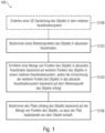
- Fig. 1 shows a schematic block representation of a method 100 for determining a path along one or more objects, whereby one object is assumed for simplicity without losing the claim to generality.
- the procedure provides an example for better understanding the determination of the path, inspecting the object and performing the continuity test of the lightning rod.
- the path is, for example, a flight route, a travel route, a diving route, etc., which (or its points) is determined in three dimensions or spatial directions in exemplary embodiments.
- the method 100 includes steps S102, S104 and S106.
- Step S102 includes determining a reference point of the object in absolute coordinates.
- the absolute coordinates are, for example, GPS coordinates, i.e.
- the absolute coordinates can be determined with a deviation of less than 10cm, less than 1cm or less than 0.5cm. This can be achieved, for example, using RTK (Real Time Kinematics) systems for measurement, which can achieve an accuracy of, for example, one centimeter or more or better.
- RTK Real Time Kinematics
- Step S104 includes determining a set of points of the object in absolute coordinates based on further points of the object in a relative coordinate system, wherein the conversion of the further points of the object into the absolute coordinate system takes place based on the reference point of the.
- the set of points can include the reference point and other points.
- grid points of the object can form the set of points of the object.
- the absolute coordinates e.g. GPS coordinates
- Relevant grid points can be those grid points that face the path.
- the grid point density of the object or the surface of the object for which the absolute coordinates are determined can be greater in an area facing the path than in other areas of the object that the path does not pass (directly).
- the other points (or vertices) can be (grid) points of the outer shell or the surface of the object.
- the relative coordinate system can, for example, be the CAD coordinate system in which the 3D model exists.
- simple dimensions ie measurements or dimensions of the object
- the relative coordinate system is introduced to differentiate it from the absolute coordinate system in order to make it clear that navigation in the relative coordinate system is not possible.
- Step S106 includes determining the path along the object based on the set of points of the object so that the path is spaced from the object.
- the method 100 may have a further step S108.
- Step S108 includes creating a 3D representation of the object in the relative coordinate system. This precedes finding the set of points of the object.
- step S108 can be carried out before or in parallel with step s102 or before step S104.
- the 3D representation can be created using CAD systems.
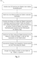
- Fig. 2 shows a schematic block representation of a method 101 for automatically inspecting an object.
- the method 101 has the steps of the method 100. These are steps S102, S104, S106 and optionally S110.
- the method 101 has steps S110 and S112.
- Step S110 includes automatically moving a movable capture unit along a path along the object.
- Step S112 further includes inspecting the object along the path. To inspect the object, a sequence of images of the object can be generated or measurements can be taken on the object.
- inspecting the object includes a continuity test of a lightning rod of the object, wherein the continuity test includes a contactless detection of a field strength of a field that is emitted by a conductor in the object.
- the steps in the method can be carried out analogously to the features of the system described below.
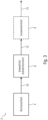
- Fig. 3 shows a schematic block representation of a system 2 for automatically inspecting an object.
- the system 2 has a computing unit 4 and a movable recording unit 6.
- the computing unit 4 is designed to determine a reference point of the object in absolute coordinates, to determine further points of the object relative to the reference point in order to obtain a set of points of the object in absolute coordinates and to determine the path 10 along the object based on the set of Points of the object to determine so that the path is spaced from the object.
- the computing unit is designed to carry out the method steps of method 100.
- the computing unit can also be arranged centrally, ie, for example, at a pilot or in a data center, in order to initially determine the path.
- the movable recording unit can then save the path.
- the movable recording unit can be connected to the computing unit or a Have partial computing unit in order to be able to track the path, for example according to the deviation of the reference point from its current position to its original position.
- a receiver for the absolute position data eg GPS
- GPS can also be arranged in the movable recording unit.
- the movable recording unit 6 can also inspect the object along the path. During or after the inspection, the recording unit 6 can output an output signal 12.
- inspecting the object includes generating a sequence of images of the object or performing a measurement on the object.
- inspecting the object includes a continuity test of a lightning rod of the object, wherein the continuity test includes a contactless detection of a field strength of a field that is emitted by a conductor in the object.
- the output signal 12 can be an image or a sequence of images or one (or more) measurement results.
- the recording unit can therefore be a camera which, in order to make it movable, is attached, for example, to a drone or a robot, etc.
- Movable here refers to the possibility of moving the recording unit along a path or following the path. Mobility can extend to all spatial directions.
- the movable recording unit can be a robot, boat, submarine, drone, airplane, etc. equipped with a (photo) camera.
- the camera can take images using any imaging method (time of flight, x-ray, photography, etc.).
- sensors can be used to determine/record properties of the object.
- the system 2 also has an evaluation unit 8, which evaluates the output signal 12. If the movable recording unit has recorded a sequence of images of the object, the evaluation unit 8 can project these images onto a model of the object in order to obtain a model 14 with the current surface of the object.
- the current surface is therefore formed by the captured images.
- the sequence of images can be a video, photos, thermal images, X-ray images, time-of-flight images, etc.
- Projecting can be done based on the GPS data, i.e. the absolute coordinates of the images or the position of the movable image recording unit.
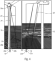
- Fig. 4 shows a schematic representation of the system according to exemplary embodiments, exemplified by a 3D representation, of a wind turbine (or blades of the wind turbine) 16. Also schematically is a drone or an unmanned flying object as a movable recording unit 18 shown. However, the movable recording unit 18 can be replaced as desired.
- a submarine is mentioned as a movable recording unit 18, which automatically inspects an object under water along a path. Navigation, ie determining the current position of the submarine, can be carried out, for example, by relaying the GPS signal, whereby the GPS signal is converted into a signal of a wavelength with which it can spread (far enough) under water.
- the exemplary embodiment is in Fig. 4 taken from two different perspectives, which also show the spatial orientation of path 20.
- the movable recording unit 18 is shown at a beginning of the path 20.
- the arrows 22a and 22b indicate an exemplary direction of flight/direction of movement of the movable recording unit 18 on the path 20.
- 20 trigger points 24 are marked as markings or points on the path.
- the points/triggering points (or a point density/triggering point density on the path) can be determined based on a field of view of the movable recording unit, for example based on a lens used on the movable recording unit (ie depending on the focal length), for example in such a way that two consecutive images partially overlay.
- the distance of the path can also be included in this determination.
- the movable recording device can generate an image of the object at these trigger points. It is of course also possible to record a video or at least a large number of images that are not optimized using the method described above, but this can increase the complexity of the evaluation.
- the trigger points can be selected so that when using a 35mm lens with a full-frame sensor, with a distance of the path to the object of 6 meters and a length of the object of 60 meters, there is a distance of 5 meters between the trigger points.
- Fig. 4 two points 26a and 26b from the set of points are shown. Starting from the points of the set of points, coordinates of the path can be determined relatively. Embodiments further use polygon areas from the set of points to which the path runs at a distance. For example, the distance can be set so that a sudden gust of wind (or other unforeseen event that can take the movable recording unit off the path) cannot press the movable recording unit against the object (or at least significantly reduces the probability) before the movable recording unit can compensate or regulate the sudden change.
- a sudden gust of wind or other unforeseen event that can take the movable recording unit off the path
- the distance can be set so that a sudden gust of wind (or other unforeseen event that can take the movable recording unit off the path) cannot press the movable recording unit against the object (or at least significantly reduces the probability) before the movable recording unit can compensate or regulate the sudden change.
- FIG. 4 an automatically created waypoint planning from original CAD and GEO data for the optical inspection of wind turbines was shown.
- Software calculates (automatically) the flight route (distance to the wind turbine blade) of the drone and the trigger points for camera recordings (points 24) depending on the focal length of the camera lens used.
- the images obtained are then projected back onto a rotor blade CAD model based on the high-precision recordings and the high-precision referencing between CAD and GPS data, resulting in a fully textured 3D model of the observation object.
- the prerequisite is the CAD model of the wind turbine or similar, as well as a single, highly precisely measured GPS anchor point (e.g. at the foot of the turbine, base point) from which the coordinate systems can be converted quickly and automatically.
- the exemplary embodiments are not limited to this. It is also shown that the drone records the wind turbine blade from two different perspectives.
- a part of the path that lies between recording the wind turbine blade from the first perspective and the second perspective can now be entered manually.
- the input can be made directly via the CAD software.
- the software can convert the relative coordinates into the absolute coordinates automatically.
- the input can also be made when the drone is already in flight. The path is then changed dynamically.
- Fig. 5 shows schematically the 3D representation of the object in relative coordinates, for example in (local) CAD coordinates. This is indicated by way of example at two points 28a, 28b of the object using the coordinate axes labeled Local CAD.
- the movable recording unit cannot yet navigate based on these coordinates, which can also only be dimensions or vectors, for example along a surface of the object.
- GPS coordinates can be divided into components of a rectangular coordinate system, the axes of which can be designated by geographic altitude, geographic latitude and geographic longitude.
- the movable recording unit can measure these absolute coordinates itself and therefore knows its current position as well as its position relative to the object.
- Fig. 6 shows the exemplary embodiment Fig. 4 and Fig. 5 . Furthermore shows Fig. 6
- the target point can be a point from the set of points of the object from which the surface of the object is spanned in the 3D representation. Alternatively, any other location on the object can be selected.
- the recording direction (or heading) refers to the orientation of a camera that is mounted on the drone, for example. The camera can then be aligned with the target point (also heading target point) so that it is, for example, (if possible) in the middle of the recorded image.
- the recording direction is determined, for example, via a pitch-and-roll (e.g. roll-pitch-yaw angle) sensor, i.e.
- This sensor can be a (3-axis) gyroscope.
- a position of the recording unit can be changed or the recording unit can be rotated in such a way that it points in the direction of the target point.
- a goal can be the automatic creation of flight routes (e.g. for wind turbine inspection with drones) based on waypoints inside or outside objects (indoor, buildings, outdoor).
- a local coordinate system of the CAD object of the construction data (of the wind turbine) can be converted into an absolute geographical coordinate system (geo-centered coordinate system GCC).
- GCC geographical coordinate system
- the real object can also be measured separately so that the (grid) points of the real object are directly available in absolute geographical coordinates.
- An absolute GPS position is calculated for each grid point of the CAD object (coordinate), i.e. the vertices are converted into GPS (GCC) coordinates.
- GCC GPS
- the specially developed algorithms Local2GCC and GCC2GDC can be used for this. Due to modern GPS technologies and the use of RTK (Real Time Kinematics) correction systems, positioning accuracies of up to one centimeter are possible. This means that if you convert the coordinates of the object into geographical coordinates as described, you can automatically generate a flight path along the object, e.g. of a drone, by simply determining the distance, or determine or change it interactively in a corresponding software engine.
- the purpose is to place 3D models defined in Cartesian and local coordinates on a globe by specifying a point on the globe and the coordinate system to use. This can be done by implementing, for example, the above-mentioned functions LOCAL2GCC and GCC2GDC in a 3D engine software.
- LOCAL2GCC a Cartesian point from the model coordinate system is converted into geocentric coordinates (also Cartesian but relative to the center of the globe).
- the GCC2GDC function then converts these into geodetic coordinates (latitude, longitude, altitude).
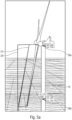
- Fig. 7 illustrates an exemplary embodiment of the present invention according to which the movable recording unit is designed to detect a field strength of a field in a non-contact or non-contact manner that is emitted by a conductor in the object to be inspected.
- a lightning protection measurement includes a non-contact continuity test of the lightning rod of a rotor blade of the wind turbine, which can be designed, for example, as a conductor and/or conductive network.
- Fig. 7 shows a rotor blade 30 of a wind turbine, which is arranged on the hub 32.
- the lightning rod 34 is shown schematically and extends from the hub 32 almost to the tip 30a of the rotor blade 30.
- a testing system 42 is arranged in the nacelle of the wind turbine, which is in Fig. 7 is shown schematically and comprises a signal generator which can be connected to the lightning rod in order to apply a signal to the lightning rod which causes the field to be detected.
- the field 44 generated by the excitation is detected by a field sensor on a drone 46, which flies over the rotor blade 30.
- an evaluation unit 48 is provided, which is designed as part of the drone or as a unit arranged remotely from it and evaluates the detected field.
- the signal applied to the lightning rod 34 causes a field to be radiated by the lightning rod, and based on the radiated field, a continuity test of the lightning rod 34 is performed.
- the signal is applied to the lightning rod 34, for example via the testing system 42 at the tip of a wind turbine, and the movable recording unit 46 is designed to measure the field strength in the lightning rod or along the lightning rod. A direction and an intensity of the detected field strength can be evaluated to determine an interruption in the conductor 34. If the measurement results in a field that is continuous within predetermined tolerances, it is concluded that there is an uninterrupted line or earth line, i.e. a functional lightning rod. If the field strength at one or more positions along the conductor deviates from a specified range, it is concluded that the line or ground line is broken.
- the conductor or lightning rod has a first end to which the signal from the test system can be applied and a second end which is open or idle.
- the conductor thus forms a dipole and the signal generator of the test system 42 preferably operates at a frequency of 13.56 MHz in the shortwave band ISM.
- Excitation of the conductor by an alternating current or voltage from the signal generator causes a standing wave along the conductor and an alternating electric field 44 that is perpendicular to the conductor.
- the electric field 44 is detected by a field sensor, preferably a 3D E-field sensor, on a drone 46 that flies over the rotor blade 30.
- the conductor or lightning rod is a closed conductor loop.
- the signal generator of the test system 42 applies a signal, for example a direct current or a direct voltage, to the conductor loop to cause current to flow in the conductor loop.
- the flow of current creates an electromagnetic field that surrounds the conductor.
- the electromagnetic field is detected by a field sensor, preferably a 3D EM field sensor, on the drone that flies over the rotor blade.
- the evaluation unit 48 evaluates the detected electromagnetic field in the manner described above.
- aspects have been described in connection with a device, it is understood that these aspects also represent a description of the corresponding method, so that a block or a component of a device is also to be understood as a corresponding method step or as a feature of a method step. Similarly, aspects described in connection with or as a method step also represent a description of a corresponding block or detail or feature of a corresponding device.
- Some or all of the method steps may be performed by a hardware apparatus (or using a hardware device). Apparatus), such as a microprocessor, a programmable computer or an electronic circuit. In some embodiments, some or more of the key process steps may be performed by such apparatus.
- embodiments of the invention may be implemented in hardware or in software.
- the implementation may be using a digital storage medium such as a floppy disk, a DVD, a BluRay Disc, a CD, a ROM, a PROM, an EPROM, an EEPROM or a FLASH memory, a hard drive or other magnetic or optical Memory can be carried out on which electronically readable control signals are stored, which can interact or interact with a programmable computer system in such a way that the respective method is carried out. Therefore, the digital storage medium can be computer readable.
- Some embodiments according to the invention thus include a data carrier that has electronically readable control signals that are capable of interacting with a programmable computer system such that one of the methods described herein is carried out.
- embodiments of the present invention may be implemented as a computer program product with a program code, the program code being effective to perform one of the methods when the computer program product runs on a computer.
- the program code can, for example, also be stored on a machine-readable medium.
- an exemplary embodiment of the method according to the invention is therefore a computer program that has a program code for carrying out one of the methods described herein when the computer program runs on a computer.
- a further exemplary embodiment of the method according to the invention is therefore a data carrier (or a digital storage medium or a computer-readable medium) on which the computer program for carrying out one of the methods described herein is recorded.
- a further exemplary embodiment of the method according to the invention is therefore a data stream or a sequence of signals which represents the computer program for carrying out one of the methods described herein.
- the data stream or the sequence of signals can, for example, be configured to be transferred via a data communication connection, for example via the Internet.
- Another embodiment includes a processing device, such as a computer or a programmable logic device, configured or adapted to perform one of the methods described herein.
- a processing device such as a computer or a programmable logic device, configured or adapted to perform one of the methods described herein.
- Another embodiment includes a computer on which the computer program for performing one of the methods described herein is installed.
- a further embodiment according to the invention includes a device or system designed to transmit a computer program to a receiver for carrying out at least one of the methods described herein.
- the transfer can be done electronically or optically, for example.
- the recipient may be, for example, a computer, a mobile device, a storage device or a similar device.
- the device or system can, for example, comprise a file server for transmitting the computer program to the recipient.
- a programmable logic device e.g., a field programmable gate array, an FPGA
- a field programmable gate array may cooperate with a microprocessor to perform any of the methods described herein.
- the methods are performed by any hardware device. This can be universally applicable hardware such as a computer processor (CPU) or hardware specific to the method, such as an ASIC.
Landscapes
- Engineering & Computer Science (AREA)
- Physics & Mathematics (AREA)
- General Physics & Mathematics (AREA)
- Aviation & Aerospace Engineering (AREA)
- Remote Sensing (AREA)
- Automation & Control Theory (AREA)
- Geometry (AREA)
- Radar, Positioning & Navigation (AREA)
- Theoretical Computer Science (AREA)
- Software Systems (AREA)
- Computer Graphics (AREA)
- Computational Mathematics (AREA)
- Mathematical Optimization (AREA)
- Pure & Applied Mathematics (AREA)
- Computer Hardware Design (AREA)
- Evolutionary Computation (AREA)
- General Engineering & Computer Science (AREA)
- Mathematical Analysis (AREA)
- Length Measuring Devices By Optical Means (AREA)
- Control Of Position, Course, Altitude, Or Attitude Of Moving Bodies (AREA)
- Position Fixing By Use Of Radio Waves (AREA)
- Length Measuring Devices With Unspecified Measuring Means (AREA)
Description
Die vorliegende Erfindung bezieht sich auf ein System und ein Verfahren zum automatischen Inspizieren eines Objekts, wobei es sich bei dem Objekt um ein Windrad handelt, zum Bestimmen eines Pfades entlang des Objekts und zur Durchgangsprüfung eines Blitzableiters des Objekts.The present invention relates to a system and method for automatically inspecting an object, the object being a wind turbine, determining a path along the object, and testing continuity of a lightning rod of the object.
Bisher werden Kameras z.B. an Drohnen zur Inspizierung von Objekten von einem Piloten ferngesteuert. Hierbei treten jedoch verschiedene Nachteile auf. So kann die Überwachung der Position der Drohne nur rein visuell ohne elektronische Hilfsmittel erfolgen. Der Pilot verfolgt die Kamera demnach mit dem Auge und steuert diese vom Boden aus. Insbesondere bei weit entfernten Objekten wie z.B. den Blättern eines Windrads ist dies für den Piloten schwierig zu bewerkstelligen, da die Kamera zum einen sehr klein wird und teilweise kaum noch zu erkennen ist und ferner bei hoch gelegenen Objekten der Kopf weit in den Nacken gelegt werden muss. Auch die Steuerung der Kamera anhand eines Monitors, der das Kamerabild anzeigt, schafft keine Abhilfe, da hier ausschließlich die Sicht aus der "Ich-Perspektive" (First Person View) der Kamera verfügbar ist und keine Draufsicht auf die Drohne. Ferner haben beide Verfahren den Nachteil, dass eine bestimmte Stelle, beispielsweise dort wo ein Defekt erkannt wurde, nur nach Augenmaß erneut angeflogen werden kann, um die Stelle genauer zu inspizieren. Weiterhin ist mit dieser Handsteuerung weder eine Positionierung der Drohne mit einem konstanten Abstand zu einem Objekt, noch eine genaue Ausrichtung der Kamera zu dem Objekt noch eine Definition exakter Auslösepunkte einer Kamera zum Fotografieren des Objekts möglich. Somit ist eine Vermessung (bzw. Vermassung), d.h. die Bestimmung einer Größe von möglichen Fehler erschwert, da der Field-of-View des Bildes nicht bekannt ist.To date, cameras on drones, for example, have been remotely controlled by a pilot to inspect objects. However, there are various disadvantages here. This means that the drone's position can only be monitored visually without any electronic aids. The pilot follows the camera with his eye and controls it from the ground. This is particularly difficult for the pilot to accomplish when dealing with objects that are far away, such as the blades of a wind turbine, as the camera becomes very small and can hardly be seen in some cases, and the head also has to be tilted far back when dealing with high-up objects . Controlling the camera using a monitor that displays the camera image does not help either, as only the view from the camera's "first person view" is available and no top view of the drone. Furthermore, both methods have the disadvantage that a specific location, for example where a defect was detected, can only be flown to again by eye in order to inspect the location more closely. Furthermore, with this hand control it is neither possible to position the drone at a constant distance from an object, nor to precisely align the camera to the object, nor to define exact trigger points of a camera for photographing the object. This makes measuring (or measuring), i.e. determining the size of possible errors, more difficult because the field of view of the image is not known.
In der
Der vorliegenden Erfindung liegt somit die Aufgabe zugrunde, ein automatisierbares und kosteneffizientes Verfahren und System zur Durchführung einer Durchgangsprüfung eines Blitzableiters eines Windrads zu schaffen, ohne a priori Kenntnis einer Position des Windrads in absoluten Koordinaten
Diese Aufgabe wird durch den ein Verfahren gemäß Anspruch 1 und durch ein System gemäß Anspruch 11 gelöst. Erfindungsgemäße Weiterbildungen sind in den Unteransprüchen definiert.The present invention is therefore based on the object of creating an automatable and cost-efficient method and system for carrying out a continuity test of a lightning rod of a wind turbine, without a priori knowledge of a position of the wind turbine in absolute coordinates
This object is achieved by a method according to claim 1 and by a system according to claim 11. Further developments according to the invention are defined in the subclaims.
Ausführungsbeispiele zeigen ein Verfahren zum Bestimmen eines Pfades entlang eines Objekts. Das Verfahren umfasst einen Schritt "Bestimmen eines Referenzpunktes des Objekts in absoluten Koordinaten (z.B. Koordinaten in einem Weltkoordinatensystem)", einen Schritt "Ermitteln einer Menge von Punkten des Objekts in absoluten Koordinaten basierend auf weiteren Punkten des Objekts in einem relativen Koordinatensystem, wobei die Umrechnung der weiteren Punkte des Objekts in das absolute Koordinatensystem basierend auf dem Referenzpunkts des Objekts erfolgt" und einen Schritt "Bestimmen des Pfads entlang des Objekts basierend auf der Menge von Punkten des Objekts, so dass der Pfad beabstandet von dem Objekt verläuft".Embodiments show a method for determining a path along an object. The method includes a step "determining a reference point of the object in absolute coordinates (e.g. coordinates in a world coordinate system)", a step "determining a set of points of the object in absolute coordinates based on further points of the object in a relative coordinate system, wherein the conversion the further points of the object in the absolute coordinate system based on the reference point of the object" and a step "determining the path along the object based on the set of points of the object so that the path runs at a distance from the object".
In anderen Worten können die relativen Koordinaten als Koordinaten in einem ersten Koordinatensystem aufgefasst werden. Analog können die absoluten Koordinaten als Koordinaten in einem zweiten Koordinatensystem aufgefasst werden, wobei sich das erste Koordinatensystem von dem zweiten Koordinatensystem unterscheidet. Der Pfad bzw. Koordinaten des Pfades liegen dann beispielsweise in Koordinaten des zweiten Koordinatensystems vor, um wie in nachfolgenden Ausführungsbeispielen beschrieben, z.B. einer beweglichen Aufnahmeeinheit zu ermöglichen, dem Pfad zu folgen. In Ausführungsbeispielen kann die bewegliche Aufnahmeeinheit Koordinaten des zweiten Koordinatensystem messen bzw. bestimmen, nicht jedoch Koordinaten des ersten Koordinatensystems.In other words, the relative coordinates can be understood as coordinates in a first coordinate system. Analogously, the absolute coordinates can be understood as coordinates in a second coordinate system, whereby the first coordinate system differs from the second coordinate system. The path or coordinates of the path are then present, for example, in coordinates of the second coordinate system, in order to enable, for example, a movable recording unit to follow the path, as described in the following exemplary embodiments. In exemplary embodiments, the movable recording unit can measure or determine coordinates of the second coordinate system, but not coordinates of the first coordinate system.
Der vorliegenden Erfindung liegt die Idee zu Grunde, das Inspizieren von Objekten zu automatisieren. Hierzu ist es zunächst wichtig, dass eine Route entlang des Objekts bestimmt wird, entlang derer das Objekt inspiziert werden kann. Hierbei ist es zunächst wichtig, die genaue Position des Objekts zu ermitteln. Häufig ist jedoch nur die Bemaßung beispielsweise aus Maßzeichnungen oder (3D-) Computermodelle von dem Objekt bekannt, nicht jedoch absolute Koordinaten z.B. eines geographischen Koordinatensystems, des Objekts. Diese Koordinaten werden nachfolgend auch als relative Koordinaten bezeichnet. Um die absoluten Koordinaten zu erhalten reicht es dann jedoch aus, nur einen Punkt des Objekts absolut zu ermitteln und die weiteren Punkte in relativen Koordinaten basierend auf dem Referenzpunkt in absolute Koordinaten zu transformieren. So kann eine aufwendige Positionsbestimmung von einer Vielzahl von Referenzpunkten vermieden werden. Die absoluten Koordinaten können dann für die Positionsbestimmung des Pfads herangezogen werden, so dass auch die (Eck-) Punkte des Pfads (bzw. Polygons) in absoluten Koordinaten vorliegen.The present invention is based on the idea of automating the inspection of objects. To do this, it is first important to determine a route along the object along which the object can be inspected. It is first important to determine the exact position of the object. However, often only the dimensions of the object are known, for example from dimensional drawings or (3D) computer models, but not the absolute coordinates, for example of a geographical coordinate system, of the object. These coordinates are also referred to below as relative coordinates. In order to obtain the absolute coordinates, however, it is then sufficient to determine only one point of the object absolutely and to transform the other points in relative coordinates into absolute coordinates based on the reference point. In this way, complex position determination of a large number of reference points can be avoided. The absolute coordinates can then be used to determine the position of the path, so that the (corner) points of the path (or polygon) are also in absolute coordinates.
In Ausführungsbeispielen werden Koordinaten des Pfades relativ zu zumindest einem Punkt aus der Menge von Punkten (bzw. relativ zu dem Objekt) bestimmt. Das heißt, die Punkte des Pfades liegen in absoluten Koordinaten vor, sind jedoch nicht fest (bzw. konstant), sondern können einer Bewegung des Objekts folgen. Windräder beispielsweise werden typischerweise in den Wind gedreht, auch wenn diese nicht in Betrieb sind. Wird der Pfad nun einer Bewegung des Rotors (bzw. des Windrads) nachgeführt, so liegt dieser immer in der gleichen Position relativ zu dem Windrad, also beispielsweise den Rotorblättern. Die Bewegung des Windrads kann anhand einer Abweichung der Position des Referenzpunkts zwischen dem Ermitteln der Menge der Punkte in absoluten Koordinaten und der aktuellen Position des Referenzpunktes bestimmt werden. Da der Referenzpunkt vorteilhafterweise an der (Außen-) Oberfläche des Objekts liegt, bewegt sich dieser auch bei einer Rotation des Objekts mit. Die Rotationsachse des Objekts befindet sich typischerweise in Inneren des Objekts. Kann sich das Objekt sowohl translatorisch als auch rotatorisch bewegen, können ferner zwei Referenzpunkte an dem Objekt bestimmt werden.In exemplary embodiments, coordinates of the path are determined relative to at least one point from the set of points (or relative to the object). This means that the points of the path are in absolute coordinates, but are not fixed (or constant), but can follow a movement of the object. Wind turbines, for example, are typically turned into the wind even when they are not in operation. If the path now follows a movement of the rotor (or the wind turbine), it is always in the same position relative to the wind turbine, for example the rotor blades. The movement of the wind turbine can be determined based on a deviation in the position of the reference point between determining the set of points in absolute coordinates and the current position of the reference point. Since the reference point is advantageously located on the (outer) surface of the object, it also moves when the object rotates. The axis of rotation of the object is typically inside the object. If the object can move both translationally and rotationally, two reference points can also be determined on the object.
Bei Ausführungsbeispielen wird der Pfad, z.B. eine Flugbahn, auf dem sich eine bewegliche Einheit, z.B. eine Drohne, entlang des Objekt bewegt, basierend auf einem 3D- oder Gittermodell des Objekts festgelegt. Die lokalen Koordinaten des Modells werden über den zumindest einen Referenzpunkt in absolute Koordinaten zur Steuerung der beweglichen Einheit anhand der absoluten Koordinaten (z.B. GPS Koordinaten) umgewandelt. Bei solchen Ausführungsbeispielen kann eine Bewegung des Objekts oder eines Teils des Objekts, z.B. eines Rotorblattes eines Windrades, in dem Modell in Echtzeit abgebildet werden, so dass ausgehend von dem modifizierten Modell die Flugbahn ebenfalls in Echtzeit an die Bewegung des Objekts angepasst wird. Diejenigen Punkte der Flugbahn, die durch die Bewegung des Objekts betroffen sind, werden z.B. basierend auf den Koordinaten des modifizierten Modells angepasst. Die Bewegung des Objekts kann entweder eine kontinuierliche oder andauernde Bewegung des Objekts oder eines Teils des Objekts sein, z.B. sich im Wind drehende Rotorblätter eines Windrades, oder es ist eine Änderung einer Orientierung des Objekts oder eines Teils des Objekts, z.B. die Bewegung eines ausgekoppelten Rotorblattes eines Windrades von einer ersten Position in eine zweite Position, z.B. aufgrund einer Windbö.In exemplary embodiments, the path, eg a flight path, on which a movable unit, eg a drone, moves along the object is determined based on a 3D or grid model of the object. The local coordinates of the model are converted via the at least one reference point into absolute coordinates for controlling the movable unit based on the absolute coordinates (eg GPS coordinates). In such embodiments, a movement of the object or a part of the object, for example a rotor blade of a wind turbine, can be depicted in the model in real time, so that the trajectory is also adapted to the movement of the object in real time, starting from the modified model. For example, those points of the trajectory that are affected by the movement of the object are adjusted based on the coordinates of the modified model. The movement of the object can be either a continuous or ongoing movement of the object or a part of the object, e.g. rotor blades of a wind turbine rotating in the wind, or it is a change in an orientation of the object or part of the object, e.g. the movement of a decoupled rotor blade of a wind turbine from a first position to a second position, for example due to a gust of wind.
Die Abbildung dieser Bewegungen in das Modell ermöglicht gemäß Ausführungsbeispielen die Möglichkeit, die Flugbahn entlang des Objekts in Echtzeit an die sich ändernden Gegebenheiten anzupassen. Gemäß Ausführungsbeispielen wird eine Bewegung der Einheit, z.B. der Drohne, entlang des sich bewegenden Objekts oder entlang des sich bewegenden Teils des Objekts ermöglicht.According to exemplary embodiments, the mapping of these movements into the model makes it possible to adapt the trajectory along the object in real time to the changing circumstances. According to exemplary embodiments, movement of the unit, e.g. the drone, along the moving object or along the moving part of the object is enabled.
Die Bestimmung der Koordinaten relativ zu dem Objekt kann durch Bestimmen des Pfades anhand eines einzuhaltenden Abstands zu dem Objekt erfolgen. Hierbei kann der Abstand zu dem Objekt senkrecht zu Polygonflächen zwischen der Menge von Punkten des Objekts ermittelt werden. Dieses Verfahren ermöglicht eine optimale Positionierung des Pfades zu dem aufzunehmenden Objekt um beispielsweise Aufnahmen oder Messungen entlang des Pfades von bzw. an dem Objekt durchzuführen. Ergänzend oder alternativ kann der Pfad auch derart bestimmt werden, dass der Pfad zumindest 40%, zumindest 60% oder zumindest 80% seiner Gesamtlänge parallel zu Polygonflächen zwischen der Menge von Punkten des Objekts verläuft. Polygonflächen können benachbarte Punkte/Vertices verbinden, um die Oberfläche des Objekts aufzuspannen und ein Modell des Objekts zu erzeugen.The coordinates relative to the object can be determined by determining the path based on a distance to be maintained from the object. The distance to the object can be determined perpendicular to polygon surfaces between the set of points on the object. This method enables optimal positioning of the path to the object to be recorded, for example to carry out recordings or measurements along the path from or on the object. Additionally or alternatively, the path can also be determined in such a way that the path runs at least 40%, at least 60% or at least 80% of its total length parallel to polygonal surfaces between the set of points of the object. Polygon surfaces can connect adjacent points/vertices to span the surface of the object and create a model of the object.
Ausführungsbeispiele zeigen ferner, dass das Bestimmen des Pfades eine manuelle Eingabe des Pfades in relativen Koordinaten umfasst. Die relativen Koordinaten des Pfades können dann in absolute Koordinaten umgerechnet werden, um den Pfad (bzw. Koordinaten desselben) in absoluten Koordinaten zu erhalten. In anderen Worten ist auch eine manuelle Eingabe von Koordinaten des Pfades möglich. Diese Koordinaten können über ein CAD System eingegeben werden, d.h. sie können entlang des 3D Modells eingegeben werden. Die Eingabe der Koordinaten kann vollständig manuell erfolgen, d.h. ohne vorab (automatisch) berechneten Pfad. Ergänzend oder alternativ kann ein vorhandener Pfad manuell geändert werden, in dem z.B. einzelne Koordinaten des Pfades verschoben werden. Somit kann der Pfad sogar während sich beispielsweise eine automatische Aufnahmeeinrichtung entlang des Pfads bewegt, dynamisch angepasst werden.Embodiments further show that determining the path includes manually entering the path in relative coordinates. The relative coordinates of the path can then be converted into absolute coordinates to obtain the path (or coordinates thereof) in absolute coordinates. In other words, manual input of path coordinates is also possible. These coordinates can be entered via a CAD system, i.e. they can be entered along the 3D model. The coordinates can be entered completely manually, i.e. without a previously (automatically) calculated path. Additionally or alternatively, an existing path can be changed manually, for example by moving individual coordinates of the path. Thus, the path can be dynamically adjusted even while, for example, an automatic recording device moves along the path.
In Ausführungsbeispielen geht dem Ermitteln der Menge von Punkten das Erstellen einer 3D Darstellung des Objekts in dem relativen Koordinatensystem voran. Dies ist beispielsweise vorteilhaft, wenn noch kein 3D Modell des Objekts vorliegt, sondern nur eine Maßzeichnung oder gar keine Bemaßungen des Objekts vorliegen. Fehlen Maßangaben können diese vorab ermittelt werden oder es kann eine Interpolation zwischen zumindest 2 Punkten vorgenommen werden. So kann beispielsweise bei einem zylinderförmigen Objekt die Oberfläche aus einem bekannten Durchmesser oder Radius interpoliert werden. Dies ist analog auf andere Formen des Objekts übertragbar. Sind nun die Menge der Punkte auf der Oberfläche des Objekts aus dem 3D Modell in absoluten Koordinaten (also bezogen auf den Referenzpunkt) bekannt, kann der Pfad nun einfacher, beispielsweise mit einer der vorab beschriebenen Ausführungsbeispiele, ermittelt werden.In exemplary embodiments, determining the set of points is preceded by creating a 3D representation of the object in the relative coordinate system. This is advantageous, for example, if there is no 3D model of the object yet, but only a dimensional drawing or no dimensions of the object at all. If dimensions are missing, these can be determined in advance or an interpolation between at least 2 points can be carried out. For example, for a cylindrical object, the surface can be interpolated from a known diameter or radius. This can be transferred analogously to other forms of the object. If the number of points on the surface of the object from the 3D model is now known in absolute coordinates (i.e. based on the reference point), the path can now be determined more easily, for example using one of the exemplary embodiments described above.
Ausführungsbeispiele zeigen ferner ein Verfahren zum automatischen Inspizieren eines Objekts unter Nutzung des vorstehend beschriebenen Verfahrens. Ferner umfasst das Verfahren das automatische Bewegen einer beweglichen Aufnahmeeinheit auf einem Pfad entlang des Objekts und das Erzeugen einer Abfolge von Bildern von dem Objekt um das Objekt zu inspizieren. Dieses Verfahren kann von dem nachfolgend beschriebenen System ausgeführt werden.Embodiments further show a method for automatically inspecting an object using the method described above. The method further includes automatically moving a movable recording unit along a path along the object and generating a sequence of images of the object in order to inspect the object. This procedure can be carried out by the system described below.
Ausführungsbeispiele zeigen ferner ein System zum automatischen Inspizieren eines Objekts. Das System weist eine beweglichen Aufnahmeeinheit auf, die ausgebildet ist, sich automatisch auf einem Pfad entlang des Objekts zu bewegen. Ferner umfasst das System eine Recheneinheit, die ausgebildet ist einen Referenzpunkt des Objekts in absoluten Koordinaten zu bestimmen, weitere Punkte des Objekts relativ zu dem Referenzpunkt zu ermitteln um eine Menge von Punkten des Objekts in absoluten Koordinaten zu erhalten und den Pfads entlang des Objekts basierend auf der Menge von Punkten des Objekts zu bestimmen, so dass der Pfad beabstandet von dem Objekt verläuft. Die bewegliche Aufnahmeeinheit kann nun das Objekt entlang des Pfades inspizieren. Hierzu kann die bewegliche Aufnahmeeinheit einen Positionsbestimmer (z.B. GPS Empfänger) aufweisen, der die absoluten Koordinaten misst. Die bewegliche Aufnahmeeinheit kann dann einen Abstand zwischen dem Pfad (bzw. eines anzusteuernden Punktes auf dem Pfad) und einer ermittelten Position des Positionsbestimmers minimieren, um die bewegliche Aufnahmeeinheit entlang des Pfades zu bewegen und das Objekt von den Punkten entlang des Pfades zu inspizieren. Dieses automatisierte Verfahren (bzw. Bewegen) der Aufnahmeeinheit resultiert auch darin, dass die bewegliche Aufnahmeeinheit automatisch an einen beliebigen Punkt des Pfades und somit auch an eine beliebige Stelle des Objekts gesteuert werden kann um beispielsweise Messungen an dem Punkt vorzunehmen oder ein Bild von einer bestimmten Stelle des Objekts zu erzeugen. So in Ausführungsbeispielen während eines Übersichtsfluges eine Drohne entlang des Objekts (dem Windrad) fliegen. Auf den Aufnahmen kann dann ein potentieller Defekt erkannt werden, der jedoch in dem Übersichtsbild nicht genau erkennbar ist. Um die Auflösung des Bildes an der Stelle zu erhöhen, kann die bewegliche Aufnahmeeinheit mit einem anderen Objektiv (mit größerer Brennweite) ausgestattet werden oder an einen Punkt der näher an dem Objekt liegt als der ursprüngliche Auslösepunkt liegt, fliegen, um eine Detailaufnahme von dem potentiellen Defekt zu erzeugen.Embodiments further show a system for automatically inspecting an object. The system has a movable recording unit which is designed to automatically move along a path along the object. Furthermore, the system includes a computing unit which is designed to determine a reference point of the object in absolute coordinates, to determine further points of the object relative to the reference point in order to obtain a set of points of the object in absolute coordinates and the path along the object based on the set of points of the object so that the path is spaced from the object. The movable recording unit can now inspect the object along the path. For this purpose, the movable recording unit can have a position determiner (e.g. GPS receiver) that measures the absolute coordinates. The movable recording unit can then minimize a distance between the path (or a point to be controlled on the path) and a determined position of the position determiner in order to move the movable recording unit along the path and inspect the object from the points along the path. This automated method (or movement) of the recording unit also results in the movable recording unit being able to be automatically controlled to any point on the path and thus to any location on the object in order, for example, to take measurements at the point or to take an image of a specific one location of the object. In exemplary embodiments, a drone flies along the object (the wind turbine) during an overview flight. A potential defect can then be recognized in the images, but this cannot be clearly seen in the overview image. In order to increase the resolution of the image at that location, the movable recording unit can be equipped with a different lens (with a larger focal length) or can fly to a point that is closer to the object than the original trigger point in order to take a detailed shot of the potential to create defect.
Gemäß Ausführungsbeispielen ist die bewegliche Aufnahmeeinheit ausgebildet, zum Inspizieren des Objekts eine Messung an dem Objekt durchzuführen. Gemäß der vorliegenden Erfindung wird eine berührungslose Durchgangsprüfung eines Blitzableiters eines Windrades durchgeführt. Dazu wird eine Spannung extern (z.B. über ein entsprechendes Prüfsystem an der Spitze eines Windrads) an den Blitzableiter angelegt. Die bewegliche Aufnahmeeinheit ist ausgebildet, eine Feldstärke in dem Blitzableiter zu messen.According to exemplary embodiments, the movable recording unit is designed to carry out a measurement on the object in order to inspect the object. According to the present invention, a non-contact continuity test of a lightning rod of a wind turbine is carried out. To do this, a voltage is applied externally to the lightning rod (e.g. via an appropriate testing system at the tip of a wind turbine). The movable recording unit is designed to measure a field strength in the lightning rod.
Ausführungsbeispiele zeigen ferner die Recheneinheit, die ausgebildet ist, entlang des Pfades Auslösestellen für die beweglich Aufnahmeeinheit abhängig von einem Sichtfeld der beweglichen Aufnahmeeinheit zu definieren. Das Sichtfeld der beweglichen Aufnahmeeinheit kann z.B. durch die Brennweite und/oder Auflösung eines Objektivs der Aufnahmeeinheit beeinflusst bzw. eingestellt werden. In anderen Worten kann das Sichtfeld ein Ausschnitt der Umgebung sein, der durch die bewegliche Aufnahmeeinheit aufgenommen werden kann. Die bewegliche Aufnahmeeinheit ist nun ausgebildet, an den Auslösestellen ein Bild zu erzeugen (bzw. aufzunehmen). Dies ist vorteilhaft, da somit vorab, beispielsweise basierend auf dem verwendeten Objektiv und/oder dem Abstand des Pfads (d.h. der beweglichen Aufnahmeeinheit) von dem Objekt die Anzahl der benötigten Bilder festgelegt wird. Die Festlegung kann vorteilhafterweise örtlich erfolgen, so dass die Aufnahmeeinheit bei Erreichen einer Auslösestelle auslöst und nicht wahllos innerhalb von bestimmten Zeitabständen. Somit kann die Anzahl der Bilder (oder Aufnahmen) auf ein minimal benötigtes Maß verringert werden. Dies können für ein Blatt/Flügel eines Windrads weniger als 100 Aufnahmen, weniger als 60 Aufnahmen oder weniger als 40 Aufnahmen sein um dieses von beiden Seiten zu inspizieren. Dies reduziert den Aufwand der Auswertung der Bilder im Vergleich zu einer unkontrollierten bzw. auf einem reinen Zeitabstand basierenden Auslösen (oder sogar einem Video).Embodiments further show the computing unit, which is designed to define trigger points for the movable recording unit along the path depending on a field of view of the movable recording unit. The field of view of the movable recording unit can be influenced or adjusted, for example, by the focal length and/or resolution of a lens of the recording unit. In other words, the field of view can be a section of the environment that can be recorded by the movable recording unit. The movable recording unit is now designed to generate (or record) an image at the trigger points. This is advantageous because the number of images required is determined in advance, for example based on the lens used and/or the distance of the path (i.e. the movable recording unit) from the object. The determination can advantageously be made locally, so that the recording unit triggers when it reaches a trigger point and not randomly within certain time intervals. This means the number of images (or recordings) can be reduced to the minimum required. For a blade/wing of a wind turbine, this can be less than 100 images, less than 60 images or less than 40 images to inspect it from both sides. This reduces the effort involved in evaluating the images compared to uncontrolled triggering or triggering based purely on a time interval (or even a video).
In Ausführungsbeispielen weist das System eine Auswerteeinheit auf, die ausgebildet ist, die Bilder von dem Objekt auf ein Modell des Objekts zu projizieren, um ein Modell mit der aktuellen Oberfläche des Objekts zu erhalten. Somit können die aufgenommenen Bilder beispielsweise dem vorhandenen oder erzeugten 3D Modell überlagert werden. Die Projektion (bzw. Überlagerung) kann in Ausführungsbeispielen basierend auf einer aktuellen Position und einer Aufnahmerichtung der Aufnahmeeinheit zu einem Zeitpunkt der Bildaufnahme erfolgen. Die Bilder können somit anhand ihrer absoluten Position dem Objekt, dessen absolute Position der Menge der Punkte (bzw. der absoluten Position dessen Oberfläche) bekannt ist, überlagert werden. Die absolute Position der Bilder kann aus der realen Position der Aufnahmeeinheit und einer Ausrichtung der Aufnahmeeinheit bestimmt werden. Basierend auf einer Abweichung der Position der Aufnahmeeinheit bei der Aufnahme des Bildes von der vorgesehenen Auslösestelle Abbildungsfehler (z.B. perspektivische Verzerrungen) der Aufnahmen durch den abweichenden Aufnahmewinkel kompensiert werden.In exemplary embodiments, the system has an evaluation unit which is designed to project the images of the object onto a model of the object in order to obtain a model with the current surface of the object. This means that the captured images can, for example, be superimposed on the existing or created 3D model. In exemplary embodiments, the projection (or overlay) can take place based on a current position and a recording direction of the recording unit at a time when the image is recorded. The images can therefore be superimposed based on their absolute position on the object whose absolute position of the set of points (or the absolute position of its surface) is known. The absolute position of the images can be determined from the real position of the recording unit and an orientation of the recording unit. Based on a deviation in the position of the recording unit when recording the image from the intended trigger point, imaging errors (e.g. perspective distortions) of the recordings are compensated for by the different recording angle.
Gemäß Ausführungsbeispielen ist die bewegliche Aufnahmeeinheit ausgebildet, eine Aufnahmerichtung auf einen Punkt aus der Menge der Punkte einzustellen. In anderen Worten richtet die bewegliche Aufnahmeeinrichtung eine Kamera derart aus, dass diese auf einen vorbestimmten Punkt des Objekts ausgerichtet ist und ein Bild in diese Richtung aufnimmt, unabhängig von einer aktuellen (absoluten oder räumlichen) Position der beweglichen Aufnahmeeinrichtung. In nochmals anderen Worten ist das Heading der Aufnahmeeinrichtung auf den vorbestimmten Punkt des Objekts ausgerichtet. Somit wird sichergestellt, dass die bewegliche Aufnahmeeinheit auch den gewünschten Bildausschnitt aufnimmt und nicht beispielsweise von dem Objekt weggedreht ist. Ferner können derart auch größere Abweichungen der Aufnahmeeinheit von einer vorbestimmten Auslösestelle toleriert werden, da aufeinanderfolgende Bilder sich (ca. um einen eingestellten Wert) überlappen und somit von allen Stellen des Objekts eine Aufnahme erhalten wird ohne einen Oberflächenbereich auszulassen, der aufgenommen werden sollte. Potentiell auftretende Abbildungsfehler (dadurch, dass das Objekt nicht im rechten Winkel aufgenommen wird sondern schräg, d.h. mit einem von dem rechten Winkel abweichenden Winkel), können kompensiert werden. Wird ein Oberflächenbereich des Objekts jedoch nicht aufgenommen, so muss die bewegliche Aufnahmeeinheit diese Stelle nochmal anfliegen, um nicht auf Informationen zu diesem Oberflächenbereich verzichten zu müssen.According to exemplary embodiments, the movable recording unit is designed to set a recording direction to a point from the set of points. In other words, the movable recording device aligns a camera such that it is aligned with a predetermined point on the object and records an image in this direction, regardless of a current (absolute or spatial) position of the movable recording device. In yet other words, the heading of the recording device is aligned with the predetermined point of the object. This ensures that the movable recording unit also records the desired image section and is not, for example, turned away from the object. Furthermore, larger deviations of the recording unit from a predetermined trigger point can be tolerated in this way, since successive images overlap (approximately by a set value) and thus a recording is obtained from all parts of the object without leaving out a surface area that should be recorded. Potentially occurring imaging errors (due to the object not being photographed at a right angle but rather at an angle, i.e. at an angle that deviates from the right angle) can be compensated for. However, if a surface area of the object is not recorded, the movable recording unit must fly to this location again in order not to have to forego information about this surface area.
In anderen Worten kann die bewegliche Aufnahmeeinheit eine beliebige Auswahl, d.h. eine Teilmenge oder jeden Wert, aus den nachfolgenden Messwerten ermitteln: eine (aktuelle) absolute (z.B. GPS) Position der beweglichen Aufnahmeeinheit, eine (aktuelle) Zielposition (z.B. GPS) auf dem Pfad, eine Ausrichtung (Heading) der beweglichen Aufnahmeeinheit, wobei die Ausrichtung eine Rotation entlang einer Längsachse der beweglichen Aufnahmeeinheit (Rollen, Wanken), eine Rotation entlang einer Querachse (Nicken, Stampfen) und/oder eine Rotation entlang einer Vertikalachse (Gieren, Schlingern) umfasst. In Ausführungsbeispielen, in denen die bewegliche Aufnahmeeinheit eine Kamera umfasst, die an einem (steuerbaren) Fortbewegungsmittel (z.B. Drohne, Roboter, U-Boot, Flugzeug etc.) angebracht ist, kann die Ausrichtung sowohl des beweglichen Objekts als auch der Kamera selber erfasst werden, wobei die Kamera selber (unabhängig von dem beweglichen Objekt) um zumindest eine Achse rotiert werden kann. Aus diesen Daten kann ein Winkel der Kamera auf das Objekt derart eingestellt werden, dass die Kamera auf einen vorgegebenen Punkt des Objekts ausgerichtet. Anhand des eingestellten Winkels der Kamera (absolut zu dem Objekt oder relativ zu dem Fortbewegungsmittel) kann ferner das aufgenommene Bild derart entzerrt bzw. bearbeitet werden, als wäre es von vorne, d.h. (ungefähr) in einem 90° Winkel zu dem Objekt aufgenommen worden.In other words, the movable recording unit can determine any selection, ie a subset or each value, from the following measured values: a (current) absolute (e.g. GPS) position of the movable recording unit, a (current) target position (e.g. GPS) on the path , an alignment (heading) of the movable recording unit, wherein the orientation is a rotation along a longitudinal axis of the movable recording unit (rolling, rolling), a rotation along a transverse axis (pitching, pitching) and / or a rotation along a vertical axis (yaw, rolling) includes. In embodiments in which the movable recording unit is a camera which is attached to a (controllable) means of transport (e.g. drone, robot, submarine, aircraft, etc.), the orientation of both the movable object and the camera itself can be recorded, with the camera itself (independent of the movable Object) can be rotated about at least one axis. From this data, an angle of the camera on the object can be adjusted such that the camera is aimed at a predetermined point on the object. Based on the set angle of the camera (absolute to the object or relative to the means of transport), the recorded image can also be rectified or processed as if it had been recorded from the front, ie (approximately) at a 90 ° angle to the object.
Bevorzugte Ausführungsbeispiele der vorliegenden Anmeldung werden nachfolgend Bezug nehmend auf die beiliegenden Zeichnungen näher erläutert. Es zeigen:
- Fig. 1
- eine schematische Blockdarstellung eines Verfahrens zum Bestimmen eines Pfades entlang eines Objekts;
- Fig. 2
- eine schematische Blockdarstellung eines Verfahrens zum automatischen Inspizieren eines Objekts;
- Fig. 3
- eine schematische Darstellung eines Systems zum automatischen Inspizieren eines Objekts;
- Fig. 4
- eine schematische Darstellung eines Pfads entlang eines Objekts gemäß einem Ausführungsbeispiel;
- Fig. 5
- eine schematische Darstellung der Umrechnung von Punkten eines Objekts in relativen oder lokalen Koordinaten (
Fig. 5a ) in absolute Koordinaten (Fig. 5b ) anhand eines Ausführungsbeispiels; - Fig. 6
- eine schematische Darstellung der Einstellung der Blickwinkel einer beweglichen Aufnahmeeinrichtung gemäß Ausführungsbeispielen; und
- Fig. 7
- ein Ausführungsbeispiel gemäß dem die bewegliche Aufnahmeeinheit ausgebildet ist, eine Feldstärke eines elektrischen Feldes berührungslos bzw. kontaktlos zu erfassen, dass durch einen Stromfluss in einem Leiter in einem zu inspizierenden Objekt hervorgerufen wird.
- Fig. 1
- a schematic block representation of a method for determining a path along an object;
- Fig. 2
- a schematic block diagram of a method for automatically inspecting an object;
- Fig. 3
- a schematic representation of a system for automatically inspecting an object;
- Fig. 4
- a schematic representation of a path along an object according to an embodiment;
- Fig. 5
- a schematic representation of the conversion of points of an object in relative or local coordinates (
Fig. 5a ) into absolute coordinates (Fig. 5b ) using an exemplary embodiment; - Fig. 6
- a schematic representation of the adjustment of the viewing angles of a movable recording device according to exemplary embodiments; and
- Fig. 7
- an embodiment according to which the movable recording unit is designed to detect a field strength of an electric field in a non-contact or non-contact manner that is caused by a current flow in a conductor in an object to be inspected.
In der nachfolgenden Beschreibung der Figuren werden gleiche oder gleichwirkende Elemente mit den gleichen Bezugszeichen versehen, so dass deren Beschreibung in den unterschiedlichen Ausführungsbeispielen untereinander austauschbar ist.In the following description of the figures, elements that are the same or have the same effect are given the same reference numerals so that their description can be interchanged in the different exemplary embodiments.
Zunächst werden zusätzlich zu Ausführungsbeispielen auch weitere Beispiele beschrieben, die für das Verständnis der Erfindung nützlich sind.First, in addition to exemplary embodiments, further examples are described that are useful for understanding the invention.
Schritt S104 umfasst das Ermitteln einer Menge von Punkten des Objekts in absoluten Koordinaten basierend auf weiteren Punkten des Objekts in einem relativen Koordinatensystem, wobei die Umrechnung der weiteren Punkte des Objekts in das absolute Koordinatensystem basierend auf dem Referenzpunkt des erfolgt. Die Menge von Punkten kann den Referenzpunkt sowie weitere Punkte aufweisen. In anderen Worten können Gitterpunkte des Objekts die Menge von Punkten des Objekts bilden. Für jeden (relevanten) Gitterpunkt sind die absoluten Koordinaten (z.B. GPS Koordinaten) bekannt bzw. werden ermittelt. Relevante Gitterpunkte können solche Gitterpunkte sein, die dem Pfad zugewandt sind. In anderen Worten kann die Gitterpunktdichte des Objekts bzw. der Oberfläche des Objekts, für die die absoluten Koordinaten bestimmt werden, an einem dem Pfad zugewandten Bereich größer sein als an anderen Bereichen des Objekts, an denen der Pfad nicht (direkt) vorbeiführt. Die weiteren Punkte (bzw. Vertices) können (Gitter-) Punkte der Außenhülle bzw. der Oberfläche des Objekts sein.Step S104 includes determining a set of points of the object in absolute coordinates based on further points of the object in a relative coordinate system, wherein the conversion of the further points of the object into the absolute coordinate system takes place based on the reference point of the. The set of points can include the reference point and other points. In other words, grid points of the object can form the set of points of the object. The absolute coordinates (e.g. GPS coordinates) are known or determined for each (relevant) grid point. Relevant grid points can be those grid points that face the path. In other words, the grid point density of the object or the surface of the object for which the absolute coordinates are determined can be greater in an area facing the path than in other areas of the object that the path does not pass (directly). The other points (or vertices) can be (grid) points of the outer shell or the surface of the object.
Das relative Koordinatensystem kann z.B. das CAD Koordinatensystem sein, in dem das 3D Modell vorliegt. Alternativ können auch einfache Bemaßungen (d.h. Maßangaben bzw. Abmessungen des Objekts) als ein relatives Koordinatensystem betrachtet werden. In anderen Worten wird das relative Koordinatensystem zur Abgrenzung zu dem absoluten Koordinatensystem eingeführt um zu verdeutlichen, dass eine Navigation in dem relativen Koordinatensystem nicht möglich ist.The relative coordinate system can, for example, be the CAD coordinate system in which the 3D model exists. Alternatively, simple dimensions (ie measurements or dimensions of the object) can also be viewed as a relative coordinate system. In other words, the relative coordinate system is introduced to differentiate it from the absolute coordinate system in order to make it clear that navigation in the relative coordinate system is not possible.
Der Schritt S106 umfasst das Bestimmen des Pfads entlang des Objekts basierend auf der Menge von Punkten des Objekts, so dass der Pfad beabstandet von dem Objekt verläuft.Step S106 includes determining the path along the object based on the set of points of the object so that the path is spaced from the object.
Optional kann das Verfahren 100 einen weiteren Schritt S108 aufweisen. Der Schritt S108 umfasst das Erstellen einer 3D Darstellung des Objekts in dem relativen Koordinatensystem. Dies geht dem Ermitteln der Menge von Punkten des Objekts voran. Somit kann der Schritt S108 vor oder parallel zu dem Schritt s102 oder vor dem Schritt S104 ausgeführt werden. Das Erstellen der 3D Darstellung kann mit CAD Systemen erfolgen.Optionally, the
Die bewegliche Aufnahmeeinheit 6 kann ferner das Objekt entlang des Pfades inspizieren. Während oder nach der Inspektion kann die Aufnahmeeinheit 6 ein Ausgangssignal 12 ausgeben. In Ausführungsbeispielen umfasst das Inspizieren des Objekts das Erzeugen einer Abfolge von Bildern von dem Objekt oder das Durchführen einer Messung an dem Objekt. Darüber hinaus umfasst das Inspizieren des Objekts eine Durchgangsprüfung eines Blitzableiters des Objekts, wobei die Durchgangsprüfung ein kontaktloses Erfassen einer Feldstärke eines Feldes umfasst, dass durch einen Leiter in dem Objekt abgestrahlt wird. Somit kann das Ausgangssignal 12 ein Bild bzw. eine Abfolge von Bildern sein oder ein (oder mehrere) Messergebnis. Die Aufnahmeeinheit kann demnach eine Kamera sein, die, um sie beweglich zu machen, z.B. an einer Drohne oder einem Roboter etc. befestigt ist.The movable recording unit 6 can also inspect the object along the path. During or after the inspection, the recording unit 6 can output an
Beweglich bezieht sich hierbei auf die Möglichkeit, die Aufnahmeeinheit entlang eines Pfades zu verfahren bzw. dem Pfad zu folgen. Die Beweglichkeit kann sich auf alle (der) Raumrichtungen erstrecken. Die bewegliche Aufnahmeeinheit kann ein Roboter, Boot, U-Boot, Drohne, Flugzeug etc. mit einer (Foto-) Kamera ausgestattet sein. Die Kamera kann Aufnahmen mittels eines beliebigen bildgebenden Verfahrens (Time of Flight, Röntgen, Fotografie usw.) aufnehmen. Alternativ zu der Kamera können Sensoren zur Bestimmung/Aufnahme von Eigenschaften des Objekts verwendet werden.Movable here refers to the possibility of moving the recording unit along a path or following the path. Mobility can extend to all spatial directions. The movable recording unit can be a robot, boat, submarine, drone, airplane, etc. equipped with a (photo) camera. The camera can take images using any imaging method (time of flight, x-ray, photography, etc.). As an alternative to the camera, sensors can be used to determine/record properties of the object.
Optional weist das System 2 ferner eine Auswerteeinheit 8 auf, die das Ausgangssignal 12 auswertet. Hat die bewegliche Aufnahmeeinheit eine Abfolge von Bildern von dem Objekt aufgenommen, kann die Auswerteeinheit 8 diese Bilder auf ein Modell des Objekts projiziert, um ein Modell 14 mit der aktuellen Oberfläche des Objekts zu erhalten. Die aktuelle Oberfläche wird demnach durch die aufgenommenen Bilder gebildet. Die Abfolge von Bildern können ein Video, Fotos, Thermalbilder, Röntgenaufnahmen, Time-of-Flight Bilder usw. sein.Optionally, the
Das Projizieren kann basierend auf den GPS Daten d.h. der absoluten Koordinaten der Bilder bzw. der Position der beweglichen Bildaufnahmeeinheit erfolgen. Hierzu können die Aufnahmen mit den GPS Koordinaten der Auslösestellen (=Auswerteeinheit) versehen werden (RTK Genauigkeit beispielsweise ca. 1 cm), so dass die Texturen auf das GPS Koordinatenmodell (3D Modell) projiziert werden können.Projecting can be done based on the GPS data, i.e. the absolute coordinates of the images or the position of the movable image recording unit. For this purpose, the recordings can be provided with the GPS coordinates of the trigger points (=evaluation unit) (RTK accuracy, for example approx. 1 cm), so that the textures can be projected onto the GPS coordinate model (3D model).
Das Ausführungsbeispiel ist in
Der Auslösepunkte können beispielsweise so gewählt werden, dass bei Einsatz eines 35mm Objektivs mit einem Vollbildsensor, bei einem Abstand des Pfades zu dem Objekt von 6 Metern und einer Länge des Objekts von 60 Metern ein Abstand von 5 Metern zwischen den Auslösepunkten liegt.For example, the trigger points can be selected so that when using a 35mm lens with a full-frame sensor, with a distance of the path to the object of 6 meters and a length of the object of 60 meters, there is a distance of 5 meters between the trigger points.
Ferner sind in
In anderen Worten ist in
In
In anderen Worten kann ein Ziel die automatische Erstellung von Flugrouten (z.B. für die Windkraftanlageninspektion mit Drohnen) auf Basis von Wegepunkten innerhalb oder außerhalb von Objekten (indoor, Gebäuden, Outdoor) sein. Dazu kann ein lokales Koordinatensystem des CAD-Objektes der Konstruktionsdaten (des Windrads) umgerechnet werden in ein absolutes geographisches Koordinatensystem (Geo-Centered-Coordinatesystem GCC). Dabei werden erstmals keine relativen Koordinaten erhalten, sondern absolute. Jeder Koordinatenpunkt hat einen unabhängigen Wert von dem Anderen. Das reale Objekt kann allerdings auch separat vermessen werden, so dass die (Gitter-) Punkte des realen Objekts direkt in absoluten geographischen Koordinaten vorliegen.In other words, a goal can be the automatic creation of flight routes (e.g. for wind turbine inspection with drones) based on waypoints inside or outside objects (indoor, buildings, outdoor). For this purpose, a local coordinate system of the CAD object of the construction data (of the wind turbine) can be converted into an absolute geographical coordinate system (geo-centered coordinate system GCC). For the first time, no relative coordinates are obtained, but absolute ones. Each coordinate point has an independent value from the other. However, the real object can also be measured separately so that the (grid) points of the real object are directly available in absolute geographical coordinates.
Für jeden Gitterpunkt des CAD Objektes (Koordinate) wird eine absolute GPS Position errechnet, d.h. die Vertices werden in GPS (GCC) Koordinaten überführt. Dazu können die eigens entwickelten Algorithmen Local2GCC und GCC2GDC verwendet werden. Auf Grund der modernen GPS Technologien und der Verwendung von z.B. RTK (Real Time Kinematik) Korrektursystemen sind Positionsgenauigkeiten bis zu einem Zentimeter möglich. Das bedeutet, dass man, wenn man die Koordinaten des Objektes in geographische Koordinaten wie beschrieben umrechnet, durch einfache Abstandsbestimmung einen Flugweg entlang des Objektes z.B. einer Drohne automatisch generieren, oder interaktiv in einer entsprechenden Software-Engine bestimmen oder verändern kann.An absolute GPS position is calculated for each grid point of the CAD object (coordinate), i.e. the vertices are converted into GPS (GCC) coordinates. The specially developed algorithms Local2GCC and GCC2GDC can be used for this. Due to modern GPS technologies and the use of RTK (Real Time Kinematics) correction systems, positioning accuracies of up to one centimeter are possible. This means that if you convert the coordinates of the object into geographical coordinates as described, you can automatically generate a flight path along the object, e.g. of a drone, by simply determining the distance, or determine or change it interactively in a corresponding software engine.
Der Zweck ist, in kartesischen und lokalen Koordinaten definierte 3D Modelle auf einem Globus zu platzieren, indem man einen Punkt auf dem Globus und das zu verwendende Koordinatensystem angibt. Dies kann durch Implementierung beispielsweise der o.g. Funktionen LOCAL2GCC und GCC2GDC in einer 3D-Engine-Software erfolgen. Mit LOCAL2GCC wird ein kartesischer Punkt aus dem Modellkoordinatensystem in geozentrische Koordinaten (ebenso kartesisch aber relativ zum Zentrum des Globus) umgerechnet. Die Funktion GCC2GDC konvertiert diese dann in geodätische Koordinaten (Latitude, Longitude, Altitude).The purpose is to place 3D models defined in Cartesian and local coordinates on a globe by specifying a point on the globe and the coordinate system to use. This can be done by implementing, for example, the above-mentioned functions LOCAL2GCC and GCC2GDC in a 3D engine software. With LOCAL2GCC, a Cartesian point from the model coordinate system is converted into geocentric coordinates (also Cartesian but relative to the center of the globe). The GCC2GDC function then converts these into geodetic coordinates (latitude, longitude, altitude).
In der Praxis bedeutet das neuartige Anwendungen für viele Bereiche, wie z.B. Automatischer Drohnenflug (alle denkbaren Flugobjekte und Routen), inklusive Landung und Start ohne Piloten, Navigation in Gebäuden (indoor Navigation), Navigation außerhalb von Gebäuden (Outdoornavigation), Überwachung (Survailance), Flugkörpersteuerung mit Terrainfollowing (Oberflächenverfolgung/Terrainverfolgung) mit gleichen Abstand zur Oberfläche..In practice, this means novel applications for many areas, such as automatic drone flight (all conceivable flying objects and routes), including landing and take-off without a pilot, navigation in buildings (indoor navigation), navigation outside of buildings (outdoor navigation), surveillance (survailance) , Missile control with terrain following (surface tracking/terrain tracking) at the same distance from the surface.
Somit wird gemäß diesem Ausführungsbeispiel durch das an den Blitzableiter 34 angelegte Signal ein Feld hervorgerufen, das durch den Blitzableiter abgestrahlt wird, und basierend auf dem abgestrahlten Feld wird eine Durchgangsprüfung des Blitzableiters 34 durchgeführt. Das Signal wird z.B. über das Prüfsystem 42 an der Spitze eines Windrads an den Blitzableiter 34 angelegt und die bewegliche Aufnahmeeinheit 46 ist ausgebildet, die Feldstärke in dem Blitzableiter bzw. entlang des Blitzableiters zu messen. Eine Richtung und eine Intensität der erfassten Feldstärke kann ausgewertet werden, um eine Unterbrechung des Leiters 34 zu bestimmen. Ergibt die Messung ein in vorbestimmten Toleranzen kontinuierliches Feld, so wird auf eine nicht-unterbrochene Leitung bzw. Erdleitung geschlossen, also einen funktionsfähigen Blitzableiter. Weicht die Feldstärke an einer oder mehreren Positionen entlang des Leiters von einem vorgegeben Bereich ab, wird auf eine unterbrochene Leitung bzw. Erdleitung geschlossen.Thus, according to this embodiment, the signal applied to the
Gemäß dem in
Gemäß einem anderen Ausführungsbeispiel ist der Leiter bzw. Blitzableiter eine geschlossene Leiterschleife. Der Signalgenerator des Prüfsystems 42 legt ein Signal, z.B. einen Gleichstrom oder eine Gleichspannung, an die Leiterschleife an, um einen Stromfluss in der Leiterschleife zu bewirken. Der Stromfluss bewirkt ein elektromagnetisches Feld, das den Leiter umgibt. Das elektromagnetische Feld wird durch einen Feldsensor, vorzugsweise einen 3D EM-Feldsensor, an der Drohne erfasst, die das Rotorblatt abfliegt. Die Auswerteeinheit 48 wertet das erfasste elektromagnetische Feld auf die oben beschriebene Art aus.According to another exemplary embodiment, the conductor or lightning rod is a closed conductor loop. The signal generator of the
Obwohl manche Aspekte im Zusammenhang mit einer Vorrichtung beschrieben wurden, versteht es sich, dass diese Aspekte auch eine Beschreibung des entsprechenden Verfahrens darstellen, sodass ein Block oder ein Bauelement einer Vorrichtung auch als ein entsprechender Verfahrensschritt oder als ein Merkmal eines Verfahrensschrittes zu verstehen ist. Analog dazu stellen Aspekte, die im Zusammenhang mit einem oder als ein Verfahrensschritt beschrieben wurden, auch eine Beschreibung eines entsprechenden Blocks oder Details oder Merkmals einer entsprechenden Vorrichtung dar. Einige oder alle der Verfahrensschritte können durch einen Hardware-Apparat (oder unter Verwendung eines Hardware-Apparats), wie zum Beispiel einen Mikroprozessor, einen programmierbaren Computer oder einer elektronischen Schaltung durchgeführt werden. Bei einigen Ausführungsbeispielen können einige oder mehrere der wichtigsten Verfahrensschritte durch einen solchen Apparat ausgeführt werden.Although some aspects have been described in connection with a device, it is understood that these aspects also represent a description of the corresponding method, so that a block or a component of a device is also to be understood as a corresponding method step or as a feature of a method step. Similarly, aspects described in connection with or as a method step also represent a description of a corresponding block or detail or feature of a corresponding device. Some or all of the method steps may be performed by a hardware apparatus (or using a hardware device). Apparatus), such as a microprocessor, a programmable computer or an electronic circuit. In some embodiments, some or more of the key process steps may be performed by such apparatus.
Je nach bestimmten Implementierungsanforderungen können Ausführungsbeispiele der Erfindung in Hardware oder in Software implementiert sein. Die Implementierung kann unter Verwendung eines digitalen Speichermediums, beispielsweise einer Floppy-Disk, einer DVD, einer BluRay Disc, einer CD, eines ROM, eines PROM, eines EPROM, eines EEPROM oder eines FLASH-Speichers, einer Festplatte oder eines anderen magnetischen oder optischen Speichers durchgeführt werden, auf dem elektronisch lesbare Steuersignale gespeichert sind, die mit einem programmierbaren Computersystem derart zusammenwirken können oder zusammenwirken, dass das jeweilige Verfahren durchgeführt wird. Deshalb kann das digitale Speichermedium computerlesbar sein.Depending on particular implementation requirements, embodiments of the invention may be implemented in hardware or in software. The implementation may be using a digital storage medium such as a floppy disk, a DVD, a BluRay Disc, a CD, a ROM, a PROM, an EPROM, an EEPROM or a FLASH memory, a hard drive or other magnetic or optical Memory can be carried out on which electronically readable control signals are stored, which can interact or interact with a programmable computer system in such a way that the respective method is carried out. Therefore, the digital storage medium can be computer readable.
Manche Ausführungsbeispiele gemäß der Erfindung umfassen also einen Datenträger, der elektronisch lesbare Steuersignale aufweist, die in der Lage sind, mit einem programmier-baren Computersystem derart zusammenzuwirken, dass eines der hierin beschriebenen Verfahren durchgeführt wird.Some embodiments according to the invention thus include a data carrier that has electronically readable control signals that are capable of interacting with a programmable computer system such that one of the methods described herein is carried out.
Allgemein können Ausführungsbeispiele der vorliegenden Erfindung als Computerprogrammprodukt mit einem Programmcode implementiert sein, wobei der Programmcode dahin gehend wirksam ist, eines der Verfahren durchzuführen, wenn das Computerprogrammprodukt auf einem Computer abläuft.In general, embodiments of the present invention may be implemented as a computer program product with a program code, the program code being effective to perform one of the methods when the computer program product runs on a computer.
Der Programmcode kann beispielsweise auch auf einem maschinenlesbaren Träger gespeichert sein.The program code can, for example, also be stored on a machine-readable medium.
Andere Ausführungsbeispiele umfassen das Computerprogramm zum Durchführen eines der hierin beschriebenen Verfahren, wobei das Computerprogramm auf einem maschinen-lesbaren Träger gespeichert ist. Mit anderen Worten ist ein Ausführungsbeispiel des erfindungsgemäßen Verfahrens somit ein Computerprogramm, das einen Programmcode zum Durchführen eines der hierin beschriebenen Verfahren aufweist, wenn das Computerprogramm auf einem Computer abläuft.Other embodiments include the computer program for performing one of the methods described herein, the computer program being stored on a machine-readable medium. In other words, an exemplary embodiment of the method according to the invention is therefore a computer program that has a program code for carrying out one of the methods described herein when the computer program runs on a computer.
Ein weiteres Ausführungsbeispiel der erfindungsgemäßen Verfahren ist somit ein Datenträger (oder ein digitales Speichermedium oder ein computerlesbares Medium), auf dem das Computerprogramm zum Durchführen eines der hierin beschriebenen Verfahren aufgezeichnet ist.A further exemplary embodiment of the method according to the invention is therefore a data carrier (or a digital storage medium or a computer-readable medium) on which the computer program for carrying out one of the methods described herein is recorded.
Ein weiteres Ausführungsbeispiel des erfindungsgemäßen Verfahrens ist somit ein Datenstrom oder eine Sequenz von Signalen, der bzw. die das Computerprogramm zum Durchführen eines der hierin beschriebenen Verfahren darstellt bzw. darstellen. Der Datenstrom oder die Sequenz von Signalen kann bzw. können beispielsweise dahin gehend konfiguriert sein, über eine Datenkommunikationsverbindung, beispielsweise über das Internet, transferiert zu werden.A further exemplary embodiment of the method according to the invention is therefore a data stream or a sequence of signals which represents the computer program for carrying out one of the methods described herein. The data stream or the sequence of signals can, for example, be configured to be transferred via a data communication connection, for example via the Internet.
Ein weiteres Ausführungsbeispiel umfasst eine Verarbeitungseinrichtung, beispielsweise einen Computer oder ein programmierbares Logikbauelement, die dahin gehend konfiguriert oder angepasst ist, eines der hierin beschriebenen Verfahren durchzuführen.Another embodiment includes a processing device, such as a computer or a programmable logic device, configured or adapted to perform one of the methods described herein.
Ein weiteres Ausführungsbeispiel umfasst einen Computer, auf dem das Computerprogramm zum Durchführen eines der hierin beschriebenen Verfahren installiert ist.Another embodiment includes a computer on which the computer program for performing one of the methods described herein is installed.
Ein weiteres Ausführungsbeispiel gemäß der Erfindung umfasst eine Vorrichtung oder ein System, die bzw. das ausgelegt ist, um ein Computerprogramm zur Durchführung zumindest eines der hierin beschriebenen Verfahren zu einem Empfänger zu übertragen. Die Übertragung kann beispielsweise elektronisch oder optisch erfolgen. Der Empfänger kann beispielsweise ein Computer, ein Mobilgerät, ein Speichergerät oder eine ähnliche Vorrichtung sein. Die Vorrichtung oder das System kann beispielsweise einen Datei-Server zur Übertragung des Computerprogramms zu dem Empfänger umfassen.A further embodiment according to the invention includes a device or system designed to transmit a computer program to a receiver for carrying out at least one of the methods described herein. The transfer can be done electronically or optically, for example. The recipient may be, for example, a computer, a mobile device, a storage device or a similar device. The device or system can, for example, comprise a file server for transmitting the computer program to the recipient.
Bei manchen Ausführungsbeispielen kann ein programmierbares Logikbauelement (beispielsweise ein feldprogrammierbares Gatterarray, ein FPGA) dazu verwendet werden, manche oder alle Funktionalitäten der hierin beschriebenen Verfahren durchzuführen. Bei manchen Ausführungsbeispielen kann ein feldprogrammierbares Gatterarray mit einem Mikroprozessor zusammenwirken, um eines der hierin beschriebenen Verfahren durchzuführen. Allgemein werden die Verfahren bei einigen Ausführungsbeispielen seitens einer beliebigen Hardwarevorrichtung durchgeführt. Diese kann eine universell einsetzbare Hardware wie ein Computerprozessor (CPU) sein oder für das Verfahren spezifische Hardware, wie beispielsweise ein ASIC.In some embodiments, a programmable logic device (e.g., a field programmable gate array, an FPGA) may be used to perform some or all of the functionality of the methods described herein. In some embodiments, a field programmable gate array may cooperate with a microprocessor to perform any of the methods described herein. Generally, in some embodiments, the methods are performed by any hardware device. This can be universally applicable hardware such as a computer processor (CPU) or hardware specific to the method, such as an ASIC.
Die oben beschriebenen Ausführungsbeispiele stellen lediglich eine Veranschaulichung der Prinzipien der vorliegenden Erfindung dar. Es versteht sich, dass Modifikationen und Variationen der hierin beschriebenen Anordnungen und Einzelheiten anderen Fachleuten einleuchten werden. Deshalb ist beabsichtigt, dass die Erfindung lediglich durch den Schutzumfang der nachstehenden Patentansprüche und nicht durch die spezifischen Einzelheiten, die anhand der Beschreibung und der Erläuterung der Ausführungsbeispiele hierin präsentiert wurden, beschränkt sei. The embodiments described above are merely illustrative of the principles of the present invention. It will be understood that modifications and variations of the arrangements and details described herein will occur to others skilled in the art. Therefore, it is intended that the invention be limited only by the scope of the following claims and not by the specific details presented from the description and explanation of the exemplary embodiments herein.
Claims (15)
- Method of performing a conduction test of a lightning arrester (34) of a wind turbine (16), comprising:determining (S102) a reference point of the wind turbine (16) in absolute coordinates;ascertaining (S104) a set of points of the wind turbine (16) in absolute coordinates on the basis of further points of the wind turbine (16) within a relative coordinate system, conversion of the further points of the wind turbine (16) to the absolute coordinate system being effected on the basis of the reference point of the wind turbine (16);determining (S106) a path (10, 20) along the wind turbine (16) on the basis of the set of points of the wind turbine (16), so that the path (10, 20) extends at a distance from the wind turbine (16);applying a voltage to the lightning arrester;moving a movable capturing unit (6, 18, 46) on the path (10, 20) along the wind turbine (16), andinspecting the wind turbine (16) along the path (10, 20), wherein said inspecting of the wind turbine (16) includes the conduction test of the lightning arrester (34) and wherein the conduction test includes contactless sensing of a field strength of a field radiated off by a conductor within the wind turbine (16).
- Method as claimed in claim 1, wherein said determining of the path (10, 20) is effected by means of a distance from the wind turbine (16) that is to be maintained.
- Method as claimed in any of the previous claims, wherein said ascertaining of the set of points is preceded by creating a 3D representation of the wind turbine (16) within the relative coordinate system.
- Method as claimed in any of the previous claims, wherein the path (10, 20), e.g. a trajectory on which a movable unit, e.g., a drone, moves along the wind turbine (16), is specified on the basis of a 3D or lattice model of the wind turbine (16), and wherein the local coordinates of the model are converted, via the at least one reference point, to absolute coordinates for controlling the movable unit by means of the absolute coordinates (e.g. GPS coordinates).
- Method as claimed in claim 4, wherein a movement of the wind turbine (16) or of part of the wind turbine (16) is reproduced in real time in the model, and wherein, on the basis of the modified model, the trajectory is adapted in real time to the movement of the wind turbine (16).
- Method as claimed in claim 1, wherein the field strength of the field is sensed along the conductor.
- Method as claimed in one of claims 1 to 6, comprising evaluating the field strength sensed along the conductor so as to determine an interruption of the conductor, wherein a direction and intensity of the sensed field strength are evaluated so as to determine an interruption of the conductor.
- Method as claimed in any of claims 1 to 7, comprising applying a signal to the conductor so as to cause the field to be sensed.
- Method as claimed in any of claims 1 to 8, wherein the conductor is a closed conductor loop, wherein a signal applied to the conductor loop causes a flow of current within the conductor loop, which flow of current causes an electromagnetic field.
- Method as claimed in any of claims 1 to 8, wherein the field is an electric field (44) that is perpendicular to the conductor and wherein the conductor has a first end to which a signal may be applied, and a second, open end, so that the conductor acts as a dipole, wherein the signal applied to the first end has a predetermined frequency so as to generate a standing wave which causes the electric field (44).
- System for performing a conduction test of a lightning arrester (34) of a wind turbine (16), comprising, comprising:a movable capturing unit (6, 18, 46) configured to automatically move on a path (10, 20) along the wind turbine (16); anda signal generator, which can be connected to the lightning arrester, in order to apply a signal to the lightning arrester, which causes a field to be sensed;a calculating unit (4) configured todetermine a reference point of the wind turbine (16) in absolute coordinates;ascertain further points of the wind turbine (16) in relation to the reference point so as to obtain a set of points of the wind turbine (16) in absolute coordinates; anddetermine the path (10, 20) along the wind turbine (16) on the basis of the set of points of the wind turbine (16), so that the path (10, 20) extends at a distance from the wind turbine (16);wherein the movable capturing unit (6, 18, 46) is configured to inspect the wind turbine (16) along the path (10, 20), wherein inspecting the wind turbine (16) includes the conduction test of the lightning arrester (34) and wherein the movable capturing unit (6, 18, 46) is configured, for the conduction test of the wind turbine (16), to sense a field strength of a field, which is radiated off by a conductor within the wind turbine (16), in a contactless manner.
- System as claimed in claim 11, wherein the movable capturing unit (6, 18, 46) is configured, for inspecting the wind turbine (16), to generate (S112) a sequence of pictures of the wind turbine (16) or to perform a measurement on the wind turbine (16).
- System as claimed in any of claims 11 or 12, whereinthe calculating unit (4) is configured to define, along the path (10, 20), trigger locations (24) for the movable capturing unit (6, 18, 46) as a function of a visual field of the movable capturing unit (6, 18, 46); andthe movable capturing unit (6, 18, 46) is configured to generate an image at the trigger locations (24).
- System as claimed in any of claims 11 to 13, comprising an evaluating unit configured to project the images of the wind turbine (16) onto a model of the wind turbine (16) so as to obtain a model having the current surface of the wind turbine (16), wherein said projection is effected on the basis of a current position and of a capturing direction of the capturing unit (6, 18, 46) at a time of capturing.
- Computer program comprising a program code for performing the method as claimed in any of claims 1 to 10, when the program runs on a computer.
Priority Applications (1)
| Application Number | Priority Date | Filing Date | Title |
|---|---|---|---|
| EP21170972.0A EP3876065B1 (en) | 2017-03-14 | 2017-12-18 | Method for determining a path along an object, system and method for automatic inspecting an object |
Applications Claiming Priority (3)
| Application Number | Priority Date | Filing Date | Title |
|---|---|---|---|
| DE102017204242 | 2017-03-14 | ||
| DE102017205647.9A DE102017205647A1 (en) | 2017-03-14 | 2017-04-03 | METHOD FOR DETERMINING A PATH ALONG AN OBJECT, SYSTEM AND METHOD FOR AUTOMATIC INSPECTION OF AN OBJECT |
| PCT/EP2017/083355 WO2018166645A1 (en) | 2017-03-14 | 2017-12-18 | Method for determining a path along an object, system and method for automatically inspecting an object |
Related Child Applications (2)
| Application Number | Title | Priority Date | Filing Date |
|---|---|---|---|
| EP21170972.0A Division-Into EP3876065B1 (en) | 2017-03-14 | 2017-12-18 | Method for determining a path along an object, system and method for automatic inspecting an object |
| EP21170972.0A Division EP3876065B1 (en) | 2017-03-14 | 2017-12-18 | Method for determining a path along an object, system and method for automatic inspecting an object |
Publications (4)
| Publication Number | Publication Date |
|---|---|
| EP3596570A1 EP3596570A1 (en) | 2020-01-22 |
| EP3596570B1 EP3596570B1 (en) | 2021-07-21 |
| EP3596570B8 EP3596570B8 (en) | 2021-09-01 |
| EP3596570B2 true EP3596570B2 (en) | 2024-02-07 |
Family
ID=63372051
Family Applications (2)
| Application Number | Title | Priority Date | Filing Date |
|---|---|---|---|
| EP17828706.6A Active EP3596570B2 (en) | 2017-03-14 | 2017-12-18 | Method for checking the electrical continuity of a lightning conductor of a wind turbine |
| EP21170972.0A Active EP3876065B1 (en) | 2017-03-14 | 2017-12-18 | Method for determining a path along an object, system and method for automatic inspecting an object |
Family Applications After (1)
| Application Number | Title | Priority Date | Filing Date |
|---|---|---|---|
| EP21170972.0A Active EP3876065B1 (en) | 2017-03-14 | 2017-12-18 | Method for determining a path along an object, system and method for automatic inspecting an object |
Country Status (8)
| Country | Link |
|---|---|
| US (2) | US11435650B2 (en) |
| EP (2) | EP3596570B2 (en) |
| CN (1) | CN110637264B (en) |
| DE (1) | DE102017205647A1 (en) |
| DK (1) | DK3596570T4 (en) |
| ES (1) | ES2890855T5 (en) |
| FI (1) | FI3596570T4 (en) |
| WO (1) | WO2018166645A1 (en) |
Families Citing this family (12)
| Publication number | Priority date | Publication date | Assignee | Title |
|---|---|---|---|---|
| GB201802209D0 (en) * | 2018-02-09 | 2018-03-28 | Bladebug Ltd | Wind turbine blade inspection system |
| DE102019109033A1 (en) * | 2019-04-05 | 2020-10-08 | Fraunhofer-Gesellschaft zur Förderung der angewandten Forschung e.V. | Imaging device, method and computer program for thermographic measurements |
| DE102019216668A1 (en) * | 2019-10-29 | 2021-04-29 | Robert Bosch Gmbh | Method and device for controlling a movement of a lifting device and lifting device |
| DE102020102152A1 (en) | 2020-01-29 | 2021-07-29 | ENERTRAG Windstrom GmbH | Method and device for contactless testing of a lightning protection device of a rotor blade of a wind turbine |
| US11698052B2 (en) * | 2020-02-06 | 2023-07-11 | General Electric Company | Pitch control of a wind turbine based position data from position localization sensors |
| CN111414701B (en) * | 2020-03-26 | 2023-07-07 | 广西防城港核电有限公司 | Method for extracting CAD file elements and converting relative coordinates |
| DE102020210618B4 (en) | 2020-08-20 | 2022-03-17 | Top Seven Gmbh & Co. Kg | METHOD AND SYSTEM FOR OBJECT DETECTION |
| US12055412B2 (en) * | 2021-04-19 | 2024-08-06 | Nvidia Corporation | System and methods for updating high definition maps |
| DE102021123124A1 (en) | 2021-09-07 | 2023-03-09 | Spleenlab GmbH | Method for controlling an unmanned aerial vehicle for an inspection flight to inspect an object and inspection unmanned aerial vehicle |
| JP7600074B2 (en) * | 2021-10-27 | 2024-12-16 | 株式会社東芝 | MOBILE BODY MANAGEMENT DEVICE, MOBILE BODY MANAGEMENT METHOD, AND MOBILE BODY MANAGEMENT PROGRAM |
| US12221231B2 (en) * | 2022-02-03 | 2025-02-11 | The Boeing Company | Automated method and system for aircraft inspection with data validation |
| WO2023188378A1 (en) * | 2022-03-31 | 2023-10-05 | 株式会社Acsl | System, method, and program for using unmanned aircraft to estimate rotor direction/azimuth of wind power generation device, and storage medium storing program |
Family Cites Families (46)
| Publication number | Priority date | Publication date | Assignee | Title |
|---|---|---|---|---|
| US4904996A (en) | 1988-01-19 | 1990-02-27 | Fernandes Roosevelt A | Line-mounted, movable, power line monitoring system |
| DE4436197C2 (en) | 1994-10-11 | 1998-09-24 | Aloys Wobben | Wind turbine with lightning protection device |
| AU1260997A (en) * | 1996-04-22 | 1997-10-30 | Caterpillar Inc. | Method for displaying a virtual object on a display screen |
| DE19833486A1 (en) | 1998-07-24 | 2000-02-10 | Dieter Heier | Lightning conductor tester; has central safety transformer through which measurement voltage is fed to lightning conductor measurement point using single wire cable to cause test current to flow |
| ES2200564T3 (en) | 1999-11-03 | 2004-03-01 | Vestas Wind Systems A/S | HIGH INTENSITY ELECTRIC CURRENT DETECTOR. |
| WO2005033629A2 (en) | 2003-09-19 | 2005-04-14 | University Of Miami | Multi-camera inspection of underwater structures |
| JP2006027448A (en) | 2004-07-16 | 2006-02-02 | Chugoku Electric Power Co Inc:The | Aerial imaging method and apparatus using unmanned air vehicle |
| DE102005017865B4 (en) | 2005-04-19 | 2007-05-10 | Repower Systems Ag | Maintenance of the lightning protection of a wind energy plant |
| US7574035B2 (en) * | 2006-04-07 | 2009-08-11 | United Technologies Corporation | System and method for inspection of hole location on turbine airfoils |
| PT103489B (en) * | 2006-05-31 | 2008-11-28 | Omnidea Lda | MODULAR SYSTEM OF ATMOSPHERIC RESOURCE DEVELOPMENT |
| US8306747B1 (en) * | 2007-01-19 | 2012-11-06 | Starodub, Inc. | Travel way measurement system |
| US8060270B2 (en) | 2008-02-29 | 2011-11-15 | The Boeing Company | System and method for inspection of structures and objects by swarm of remote unmanned vehicles |
| KR100999412B1 (en) * | 2008-06-26 | 2010-12-09 | 한국유지관리 주식회사 | Drawing Mapping System by Acquiring Spatial Coordinates of Bridge Using GPS |
| DE102008042287A1 (en) | 2008-09-23 | 2010-03-25 | Robert Bosch Gmbh | Monitoring device for lightning conductor unit of lightning conductor system, has monitoring module for automated and unobserved monitoring of operating condition of lightning conductor unit |
| EP2491344B1 (en) * | 2009-10-22 | 2016-11-30 | TomTom Global Content B.V. | System and method for vehicle navigation using lateral offsets |
| DE102010048400A1 (en) | 2010-03-15 | 2011-09-15 | Horst Zell | Method for checking the structural condition of wind turbines |
| DE102010014358A1 (en) | 2010-04-09 | 2011-10-13 | Energiekontor Ag | Method for increasing service life of wind energy plant, involves determining measure or combination of measures by comparing lowest cost over new service life with cost without service life-extending measure over remaining service life |
| US20120136630A1 (en) * | 2011-02-04 | 2012-05-31 | General Electric Company | Method and system for wind turbine inspection |
| EP2511656A1 (en) * | 2011-04-14 | 2012-10-17 | Hexagon Technology Center GmbH | Measuring system for determining the 3D coordinates of an object surface |
| DE102011017564B4 (en) | 2011-04-26 | 2017-02-16 | Airbus Defence and Space GmbH | Method and system for inspecting a surface for material defects |
| DE102012009205A1 (en) | 2012-05-10 | 2013-11-14 | Phoenix Contact Gmbh & Co. Kg | Lightning current monitoring device |
| DE102012015353A1 (en) | 2012-08-06 | 2014-02-06 | Carl Von Ossietzky Universität Oldenburg | Rotor blade and rotor blade tip |
| DE102012214981A1 (en) | 2012-08-23 | 2014-02-27 | Suzlon Energy Gmbh | Flash sink for wind turbine, transfers entire lightning current using one conductor during failure of other conductor, and arranges conductors as inner and outer conductors concentrically with respect to each other |
| DE102013107273B4 (en) | 2013-07-10 | 2017-03-02 | Bernd SEBALD | Device for inspecting rotor blades of a wind turbine |
| DE102013217129A1 (en) | 2013-08-28 | 2015-03-05 | Robert Bosch Gmbh | Method for monitoring a lightning arrester device |
| DE102013113326A1 (en) | 2013-12-02 | 2015-06-03 | Hgz Patentvermarktungs Gmbh | Method for optical detection of a wind turbine for testing purposes with the aid of an aircraft |
| US20160216304A1 (en) * | 2015-01-28 | 2016-07-28 | Lockheed Martin Corporation | Rapid high-resolution magnetic field measurements for power line inspection |
| US9824597B2 (en) * | 2015-01-28 | 2017-11-21 | Lockheed Martin Corporation | Magnetic navigation methods and systems utilizing power grid and communication network |
| US9678506B2 (en) * | 2014-06-19 | 2017-06-13 | Skydio, Inc. | Magic wand interface and other user interaction paradigms for a flying digital assistant |
| WO2016003555A2 (en) | 2014-07-01 | 2016-01-07 | Scanifly, LLC | Device, method, apparatus, and computer-readable medium for solar site assessment |
| DE202014006541U1 (en) | 2014-08-14 | 2015-11-19 | AVAILON GmbH | Unmanned aircraft for performing a lightning protection measurement on a wind turbine |
| JP6387782B2 (en) * | 2014-10-17 | 2018-09-12 | ソニー株式会社 | Control device, control method, and computer program |
| EP3885217A1 (en) * | 2015-02-10 | 2021-09-29 | Mobileye Vision Technologies Ltd. | Sparse map for autonomous vehicle navigation |
| EP3265885A4 (en) | 2015-03-03 | 2018-08-29 | Prenav Inc. | Scanning environments and tracking unmanned aerial vehicles |
| WO2016149513A1 (en) | 2015-03-18 | 2016-09-22 | Izak Van Cruyningen | Flight planning for unmanned aerial tower inspection with long baseline positioning |
| US9928648B2 (en) * | 2015-11-09 | 2018-03-27 | Microsoft Technology Licensing, Llc | Object path identification for navigating objects in scene-aware device environments |
| CN108474848A (en) * | 2015-12-10 | 2018-08-31 | 深圳市大疆创新科技有限公司 | system and method for mobile platform operation |
| US9513635B1 (en) | 2015-12-30 | 2016-12-06 | Unmanned Innovation, Inc. | Unmanned aerial vehicle inspection system |
| WO2017210365A1 (en) * | 2016-05-31 | 2017-12-07 | Lockheed Martin Corporation | Magneto-optical detecting apparatus and methods |
| US10916969B2 (en) * | 2016-12-08 | 2021-02-09 | At&T Intellectual Property I, L.P. | Method and apparatus for providing power using an inductive coupling |
| US11017679B2 (en) * | 2017-01-13 | 2021-05-25 | Skydio, Inc. | Unmanned aerial vehicle visual point cloud navigation |
| WO2018175441A1 (en) * | 2017-03-20 | 2018-09-27 | Mobileye Vision Technologies Ltd. | Navigation by augmented path prediction |
| WO2018215833A1 (en) * | 2017-05-23 | 2018-11-29 | 1.21 Gigawatts Ltd. | Traffic monitoring and management systems and methods |
| US10540895B2 (en) * | 2017-06-21 | 2020-01-21 | International Business Machines Corporation | Management of mobile objects |
| US11170299B2 (en) * | 2018-12-28 | 2021-11-09 | Nvidia Corporation | Distance estimation to objects and free-space boundaries in autonomous machine applications |
| US20210101616A1 (en) * | 2019-10-08 | 2021-04-08 | Mobileye Vision Technologies Ltd. | Systems and methods for vehicle navigation |
-
2017
- 2017-04-03 DE DE102017205647.9A patent/DE102017205647A1/en active Pending
- 2017-12-18 ES ES17828706T patent/ES2890855T5/en active Active
- 2017-12-18 WO PCT/EP2017/083355 patent/WO2018166645A1/en unknown
- 2017-12-18 EP EP17828706.6A patent/EP3596570B2/en active Active
- 2017-12-18 CN CN201780090768.4A patent/CN110637264B/en active Active
- 2017-12-18 FI FIEP17828706.6T patent/FI3596570T4/en active
- 2017-12-18 EP EP21170972.0A patent/EP3876065B1/en active Active
- 2017-12-18 DK DK17828706.6T patent/DK3596570T4/en active
-
2019
- 2019-09-13 US US16/569,682 patent/US11435650B2/en active Active
-
2022
- 2022-06-20 US US17/844,146 patent/US11880118B2/en active Active
Non-Patent Citations (1)
| Title |
|---|
| Andreas Bircher, Kostas Alexis, Michael Burri, Philipp Oettershagen,Sammy Oman, Thomas Mantel, and Roland Siegwart; Structural Inspection Path Planning via Iterative Viewpoint Resampling withApplication to Aerial Robotics; 2015 IEEE International Conference onRobotics and Automation (ICRA) Washington State ConventionCenter; Seattle, Washington, May 26-30, 2015; Seiten 6423 - 6430 † |
Also Published As
| Publication number | Publication date |
|---|---|
| EP3596570B1 (en) | 2021-07-21 |
| FI3596570T4 (en) | 2024-03-18 |
| US11435650B2 (en) | 2022-09-06 |
| CN110637264A (en) | 2019-12-31 |
| DE102017205647A1 (en) | 2018-09-20 |
| CN110637264B (en) | 2024-01-26 |
| US11880118B2 (en) | 2024-01-23 |
| EP3596570B8 (en) | 2021-09-01 |
| US20220317546A1 (en) | 2022-10-06 |
| ES2890855T3 (en) | 2022-01-24 |
| EP3876065A1 (en) | 2021-09-08 |
| WO2018166645A1 (en) | 2018-09-20 |
| ES2890855T5 (en) | 2024-07-04 |
| US20200005655A1 (en) | 2020-01-02 |
| DK3596570T3 (en) | 2021-10-18 |
| EP3876065B1 (en) | 2025-01-15 |
| DK3596570T4 (en) | 2024-04-29 |
| EP3596570A1 (en) | 2020-01-22 |
Similar Documents
| Publication | Publication Date | Title |
|---|---|---|
| EP3596570B2 (en) | Method for checking the electrical continuity of a lightning conductor of a wind turbine | |
| DE102011017564B4 (en) | Method and system for inspecting a surface for material defects | |
| EP3430368B1 (en) | Aircraft for scanning an object, and system for damage analysis for the object | |
| WO2018167006A1 (en) | Method and arrangement for condition monitoring of a facility with operating means | |
| Eschmann et al. | High-resolution multisensor infrastructure inspection with unmanned aircraft systems | |
| EP2916106B1 (en) | Method for determining position and attitude by means of virtual reference images | |
| US20170248967A1 (en) | Unmanned aircraft for positioning an instrument for inspection purposes and methods of inspecting a target surface | |
| DE69430012T2 (en) | INTEGRATED PHOTO APPARATUS MOUNTED ON AN AIRCRAFT | |
| EP2787319A1 (en) | Control of an image triggering system for taking aerial photographs in nadir alignment for an unmanned aircraft | |
| Hawkins | Using a drone and photogrammetry software to create orthomosaic images and 3D models of aircraft accident sites | |
| WO2017174426A1 (en) | Layer thickness measurement of soil covering | |
| AT511460B1 (en) | METHOD FOR DETERMINING THE POSITION OF AN AIRCRAFT | |
| Brown et al. | Visual & inertial datasets for an evtol aircraft approach and landing scenario | |
| EP4200683B1 (en) | Method and system for object capture | |
| DE102016110477A1 (en) | Method for positioning an in particular unmanned aircraft with the aid of an active static ground station and aircraft and ground station for carrying out the method | |
| DE102023113683A1 (en) | Machine-assisted inspections of energy infrastructure | |
| DE202024105388U1 (en) | Device arrangement for recording an overall image of an environment of a watercraft and camera | |
| Armenakis et al. | Unmanned Aerial Systems for Low-Altitude Remote Sensing | |
| DE10039925A1 (en) | Abnormality and terrestrial object location and analysis method using digital aerial images in visible and IR range | |
| Kolecki et al. | A mapping platform for gyrocopters-the influence of the stabilization on data geometry | |
| Tipantuña-Topanta et al. | Virtual Environment Mapping Module to Manage Intelligent Flight in an Indoor Drone | |
| Jensen et al. | The use of a UAV as a remote sensing platform in agriculture | |
| Sargeant | Unmanned aerial vehicle payload development for aerial survey |
Legal Events
| Date | Code | Title | Description |
|---|---|---|---|
| STAA | Information on the status of an ep patent application or granted ep patent |
Free format text: STATUS: UNKNOWN |
|
| STAA | Information on the status of an ep patent application or granted ep patent |
Free format text: STATUS: THE INTERNATIONAL PUBLICATION HAS BEEN MADE |
|
| PUAI | Public reference made under article 153(3) epc to a published international application that has entered the european phase |
Free format text: ORIGINAL CODE: 0009012 |
|
| STAA | Information on the status of an ep patent application or granted ep patent |
Free format text: STATUS: REQUEST FOR EXAMINATION WAS MADE |
|
| 17P | Request for examination filed |
Effective date: 20190911 |
|
| AK | Designated contracting states |
Kind code of ref document: A1 Designated state(s): AL AT BE BG CH CY CZ DE DK EE ES FI FR GB GR HR HU IE IS IT LI LT LU LV MC MK MT NL NO PL PT RO RS SE SI SK SM TR |
|
| AX | Request for extension of the european patent |
Extension state: BA ME |
|
| DAV | Request for validation of the european patent (deleted) | ||
| DAX | Request for extension of the european patent (deleted) | ||
| STAA | Information on the status of an ep patent application or granted ep patent |
Free format text: STATUS: EXAMINATION IS IN PROGRESS |
|
| STAA | Information on the status of an ep patent application or granted ep patent |
Free format text: STATUS: EXAMINATION IS IN PROGRESS |
|
| 17Q | First examination report despatched |
Effective date: 20201214 |
|
| RAP1 | Party data changed (applicant data changed or rights of an application transferred) |
Owner name: TOP SEVEN GMBH & CO. KG |
|
| GRAP | Despatch of communication of intention to grant a patent |
Free format text: ORIGINAL CODE: EPIDOSNIGR1 |
|
| STAA | Information on the status of an ep patent application or granted ep patent |
Free format text: STATUS: GRANT OF PATENT IS INTENDED |
|
| INTG | Intention to grant announced |
Effective date: 20210504 |
|
| RIN1 | Information on inventor provided before grant (corrected) |
Inventor name: SCHICKEL, PETER Inventor name: SENG, ULRICH Inventor name: NEUBAUER, OLIVER |
|
| GRAS | Grant fee paid |
Free format text: ORIGINAL CODE: EPIDOSNIGR3 |
|
| GRAA | (expected) grant |
Free format text: ORIGINAL CODE: 0009210 |
|
| STAA | Information on the status of an ep patent application or granted ep patent |
Free format text: STATUS: THE PATENT HAS BEEN GRANTED |
|
| AK | Designated contracting states |
Kind code of ref document: B1 Designated state(s): AL AT BE BG CH CY CZ DE DK EE ES FI FR GB GR HR HU IE IS IT LI LT LU LV MC MK MT NL NO PL PT RO RS SE SI SK SM TR |
|
| REG | Reference to a national code |
Ref country code: GB Ref legal event code: FG4D Free format text: NOT ENGLISH |
|
| REG | Reference to a national code |
Ref country code: CH Ref legal event code: EP |
|
| REG | Reference to a national code |
Ref country code: DE Ref legal event code: R096 Ref document number: 502017010991 Country of ref document: DE |
|
| REG | Reference to a national code |
Ref country code: AT Ref legal event code: REF Ref document number: 1413154 Country of ref document: AT Kind code of ref document: T Effective date: 20210815 |
|
| REG | Reference to a national code |
Ref country code: CH Ref legal event code: PK Free format text: TITEL Ref country code: CH Ref legal event code: PK Free format text: BERICHTIGUNG B8 |
|
| REG | Reference to a national code |
Ref country code: IE Ref legal event code: FG4D Free format text: LANGUAGE OF EP DOCUMENT: GERMAN |
|
| REG | Reference to a national code |
Ref country code: DK Ref legal event code: T3 Effective date: 20211013 |
|
| REG | Reference to a national code |
Ref country code: FI Ref legal event code: FGE |
|
| REG | Reference to a national code |
Ref country code: NL Ref legal event code: FP |
|
| REG | Reference to a national code |
Ref country code: SE Ref legal event code: TRGR |
|
| REG | Reference to a national code |
Ref country code: LT Ref legal event code: MG9D |
|
| REG | Reference to a national code |
Ref country code: ES Ref legal event code: FG2A Ref document number: 2890855 Country of ref document: ES Kind code of ref document: T3 Effective date: 20220124 |
|
| PG25 | Lapsed in a contracting state [announced via postgrant information from national office to epo] |
Ref country code: RS Free format text: LAPSE BECAUSE OF FAILURE TO SUBMIT A TRANSLATION OF THE DESCRIPTION OR TO PAY THE FEE WITHIN THE PRESCRIBED TIME-LIMIT Effective date: 20210721 Ref country code: HR Free format text: LAPSE BECAUSE OF FAILURE TO SUBMIT A TRANSLATION OF THE DESCRIPTION OR TO PAY THE FEE WITHIN THE PRESCRIBED TIME-LIMIT Effective date: 20210721 Ref country code: PT Free format text: LAPSE BECAUSE OF FAILURE TO SUBMIT A TRANSLATION OF THE DESCRIPTION OR TO PAY THE FEE WITHIN THE PRESCRIBED TIME-LIMIT Effective date: 20211122 Ref country code: NO Free format text: LAPSE BECAUSE OF FAILURE TO SUBMIT A TRANSLATION OF THE DESCRIPTION OR TO PAY THE FEE WITHIN THE PRESCRIBED TIME-LIMIT Effective date: 20211021 Ref country code: BG Free format text: LAPSE BECAUSE OF FAILURE TO SUBMIT A TRANSLATION OF THE DESCRIPTION OR TO PAY THE FEE WITHIN THE PRESCRIBED TIME-LIMIT Effective date: 20211021 Ref country code: LT Free format text: LAPSE BECAUSE OF FAILURE TO SUBMIT A TRANSLATION OF THE DESCRIPTION OR TO PAY THE FEE WITHIN THE PRESCRIBED TIME-LIMIT Effective date: 20210721 |
|
| PG25 | Lapsed in a contracting state [announced via postgrant information from national office to epo] |
Ref country code: PL Free format text: LAPSE BECAUSE OF FAILURE TO SUBMIT A TRANSLATION OF THE DESCRIPTION OR TO PAY THE FEE WITHIN THE PRESCRIBED TIME-LIMIT Effective date: 20210721 Ref country code: LV Free format text: LAPSE BECAUSE OF FAILURE TO SUBMIT A TRANSLATION OF THE DESCRIPTION OR TO PAY THE FEE WITHIN THE PRESCRIBED TIME-LIMIT Effective date: 20210721 Ref country code: GR Free format text: LAPSE BECAUSE OF FAILURE TO SUBMIT A TRANSLATION OF THE DESCRIPTION OR TO PAY THE FEE WITHIN THE PRESCRIBED TIME-LIMIT Effective date: 20211022 |
|
| REG | Reference to a national code |
Ref country code: DE Ref legal event code: R026 Ref document number: 502017010991 Country of ref document: DE |
|
| PLBI | Opposition filed |
Free format text: ORIGINAL CODE: 0009260 |
|
| PLAX | Notice of opposition and request to file observation + time limit sent |
Free format text: ORIGINAL CODE: EPIDOSNOBS2 |
|
| REG | Reference to a national code |
Ref country code: FI Ref legal event code: MDE Opponent name: ROLAWIND GMBH |
|
| 26 | Opposition filed |
Opponent name: ROLAWIND GMBH Effective date: 20220414 |
|
| PLBB | Reply of patent proprietor to notice(s) of opposition received |
Free format text: ORIGINAL CODE: EPIDOSNOBS3 |
|
| PG25 | Lapsed in a contracting state [announced via postgrant information from national office to epo] |
Ref country code: SM Free format text: LAPSE BECAUSE OF FAILURE TO SUBMIT A TRANSLATION OF THE DESCRIPTION OR TO PAY THE FEE WITHIN THE PRESCRIBED TIME-LIMIT Effective date: 20210721 Ref country code: SK Free format text: LAPSE BECAUSE OF FAILURE TO SUBMIT A TRANSLATION OF THE DESCRIPTION OR TO PAY THE FEE WITHIN THE PRESCRIBED TIME-LIMIT Effective date: 20210721 Ref country code: RO Free format text: LAPSE BECAUSE OF FAILURE TO SUBMIT A TRANSLATION OF THE DESCRIPTION OR TO PAY THE FEE WITHIN THE PRESCRIBED TIME-LIMIT Effective date: 20210721 Ref country code: EE Free format text: LAPSE BECAUSE OF FAILURE TO SUBMIT A TRANSLATION OF THE DESCRIPTION OR TO PAY THE FEE WITHIN THE PRESCRIBED TIME-LIMIT Effective date: 20210721 Ref country code: CZ Free format text: LAPSE BECAUSE OF FAILURE TO SUBMIT A TRANSLATION OF THE DESCRIPTION OR TO PAY THE FEE WITHIN THE PRESCRIBED TIME-LIMIT Effective date: 20210721 Ref country code: AL Free format text: LAPSE BECAUSE OF FAILURE TO SUBMIT A TRANSLATION OF THE DESCRIPTION OR TO PAY THE FEE WITHIN THE PRESCRIBED TIME-LIMIT Effective date: 20210721 |
|
| PG25 | Lapsed in a contracting state [announced via postgrant information from national office to epo] |
Ref country code: MC Free format text: LAPSE BECAUSE OF FAILURE TO SUBMIT A TRANSLATION OF THE DESCRIPTION OR TO PAY THE FEE WITHIN THE PRESCRIBED TIME-LIMIT Effective date: 20210721 |
|
| REG | Reference to a national code |
Ref country code: CH Ref legal event code: PL |
|
| PG25 | Lapsed in a contracting state [announced via postgrant information from national office to epo] |
Ref country code: LU Free format text: LAPSE BECAUSE OF NON-PAYMENT OF DUE FEES Effective date: 20211218 Ref country code: IE Free format text: LAPSE BECAUSE OF NON-PAYMENT OF DUE FEES Effective date: 20211218 |
|
| PG25 | Lapsed in a contracting state [announced via postgrant information from national office to epo] |
Ref country code: LI Free format text: LAPSE BECAUSE OF NON-PAYMENT OF DUE FEES Effective date: 20211231 Ref country code: CH Free format text: LAPSE BECAUSE OF NON-PAYMENT OF DUE FEES Effective date: 20211231 |
|
| REG | Reference to a national code |
Ref country code: CH Ref legal event code: PK Free format text: TITEL |
|
| PG25 | Lapsed in a contracting state [announced via postgrant information from national office to epo] |
Ref country code: CY Free format text: LAPSE BECAUSE OF FAILURE TO SUBMIT A TRANSLATION OF THE DESCRIPTION OR TO PAY THE FEE WITHIN THE PRESCRIBED TIME-LIMIT Effective date: 20210721 |
|
| PG25 | Lapsed in a contracting state [announced via postgrant information from national office to epo] |
Ref country code: HU Free format text: LAPSE BECAUSE OF FAILURE TO SUBMIT A TRANSLATION OF THE DESCRIPTION OR TO PAY THE FEE WITHIN THE PRESCRIBED TIME-LIMIT; INVALID AB INITIO Effective date: 20171218 |
|
| APAH | Appeal reference modified |
Free format text: ORIGINAL CODE: EPIDOSCREFNO |
|
| APBM | Appeal reference recorded |
Free format text: ORIGINAL CODE: EPIDOSNREFNO |
|
| APBP | Date of receipt of notice of appeal recorded |
Free format text: ORIGINAL CODE: EPIDOSNNOA2O |
|
| APAN | Information on closure of appeal procedure modified |
Free format text: ORIGINAL CODE: EPIDOSCNOA9O |
|
| APBU | Appeal procedure closed |
Free format text: ORIGINAL CODE: EPIDOSNNOA9O |
|
| PUAH | Patent maintained in amended form |
Free format text: ORIGINAL CODE: 0009272 |
|
| STAA | Information on the status of an ep patent application or granted ep patent |
Free format text: STATUS: PATENT MAINTAINED AS AMENDED |
|
| PGFP | Annual fee paid to national office [announced via postgrant information from national office to epo] |
Ref country code: IT Payment date: 20231227 Year of fee payment: 7 |
|
| 27A | Patent maintained in amended form |
Effective date: 20240207 |
|
| AK | Designated contracting states |
Kind code of ref document: B2 Designated state(s): AL AT BE BG CH CY CZ DE DK EE ES FI FR GB GR HR HU IE IS IT LI LT LU LV MC MK MT NL NO PL PT RO RS SE SI SK SM TR |
|
| REG | Reference to a national code |
Ref country code: DE Ref legal event code: R102 Ref document number: 502017010991 Country of ref document: DE |
|
| PGFP | Annual fee paid to national office [announced via postgrant information from national office to epo] |
Ref country code: ES Payment date: 20240102 Year of fee payment: 7 |
|
| REG | Reference to a national code |
Ref country code: DK Ref legal event code: T4 Effective date: 20240424 |
|
| PG25 | Lapsed in a contracting state [announced via postgrant information from national office to epo] |
Ref country code: MK Free format text: LAPSE BECAUSE OF FAILURE TO SUBMIT A TRANSLATION OF THE DESCRIPTION OR TO PAY THE FEE WITHIN THE PRESCRIBED TIME-LIMIT Effective date: 20210721 |
|
| REG | Reference to a national code |
Ref country code: SE Ref legal event code: RPEO |
|
| REG | Reference to a national code |
Ref country code: NL Ref legal event code: FP |
|
| REG | Reference to a national code |
Ref country code: ES Ref legal event code: DC2A Ref document number: 2890855 Country of ref document: ES Kind code of ref document: T5 Effective date: 20240704 |
|
| PG25 | Lapsed in a contracting state [announced via postgrant information from national office to epo] |
Ref country code: MT Free format text: LAPSE BECAUSE OF FAILURE TO SUBMIT A TRANSLATION OF THE DESCRIPTION OR TO PAY THE FEE WITHIN THE PRESCRIBED TIME-LIMIT Effective date: 20210721 |
|
| PGFP | Annual fee paid to national office [announced via postgrant information from national office to epo] |
Ref country code: DE Payment date: 20241206 Year of fee payment: 8 |
|
| PGFP | Annual fee paid to national office [announced via postgrant information from national office to epo] |
Ref country code: DK Payment date: 20241220 Year of fee payment: 8 |
|
| PGFP | Annual fee paid to national office [announced via postgrant information from national office to epo] |
Ref country code: NL Payment date: 20241227 Year of fee payment: 8 Ref country code: BE Payment date: 20241218 Year of fee payment: 8 Ref country code: FI Payment date: 20241216 Year of fee payment: 8 |
|
| PGFP | Annual fee paid to national office [announced via postgrant information from national office to epo] |
Ref country code: GB Payment date: 20241220 Year of fee payment: 8 |
|
| PGFP | Annual fee paid to national office [announced via postgrant information from national office to epo] |
Ref country code: FR Payment date: 20241221 Year of fee payment: 8 |
|
| PGFP | Annual fee paid to national office [announced via postgrant information from national office to epo] |
Ref country code: AT Payment date: 20241218 Year of fee payment: 8 |
|
| PGFP | Annual fee paid to national office [announced via postgrant information from national office to epo] |
Ref country code: SE Payment date: 20241221 Year of fee payment: 8 |
|
| PGFP | Annual fee paid to national office [announced via postgrant information from national office to epo] |
Ref country code: TR Payment date: 20241209 Year of fee payment: 8 |