EP3596420B1 - Wiederaufnahme eines fernverfolgten, befehlsgeführten fahrzeugs in das sichtfeld des verfolgers - Google Patents
Wiederaufnahme eines fernverfolgten, befehlsgeführten fahrzeugs in das sichtfeld des verfolgers Download PDFInfo
- Publication number
- EP3596420B1 EP3596420B1 EP18720444.1A EP18720444A EP3596420B1 EP 3596420 B1 EP3596420 B1 EP 3596420B1 EP 18720444 A EP18720444 A EP 18720444A EP 3596420 B1 EP3596420 B1 EP 3596420B1
- Authority
- EP
- European Patent Office
- Prior art keywords
- missile
- command
- vehicle
- tracker
- actuator command
- Prior art date
- Legal status (The legal status is an assumption and is not a legal conclusion. Google has not performed a legal analysis and makes no representation as to the accuracy of the status listed.)
- Active
Links
Images



Classifications
-
- F—MECHANICAL ENGINEERING; LIGHTING; HEATING; WEAPONS; BLASTING
- F41—WEAPONS
- F41G—WEAPON SIGHTS; AIMING
- F41G7/00—Direction control systems for self-propelled missiles
- F41G7/20—Direction control systems for self-propelled missiles based on continuous observation of target position
- F41G7/30—Command link guidance systems
- F41G7/301—Details
- F41G7/303—Sighting or tracking devices especially provided for simultaneous observation of the target and of the missile
-
- F—MECHANICAL ENGINEERING; LIGHTING; HEATING; WEAPONS; BLASTING
- F41—WEAPONS
- F41G—WEAPON SIGHTS; AIMING
- F41G7/00—Direction control systems for self-propelled missiles
- F41G7/20—Direction control systems for self-propelled missiles based on continuous observation of target position
- F41G7/30—Command link guidance systems
- F41G7/32—Command link guidance systems for wire-guided missiles
-
- G—PHYSICS
- G01—MEASURING; TESTING
- G01S—RADIO DIRECTION-FINDING; RADIO NAVIGATION; DETERMINING DISTANCE OR VELOCITY BY USE OF RADIO WAVES; LOCATING OR PRESENCE-DETECTING BY USE OF THE REFLECTION OR RERADIATION OF RADIO WAVES; ANALOGOUS ARRANGEMENTS USING OTHER WAVES
- G01S3/00—Direction-finders for determining the direction from which infrasonic, sonic, ultrasonic or electromagnetic waves, or particle emission, not having a directional significance, are being received
- G01S3/78—Direction-finders for determining the direction from which infrasonic, sonic, ultrasonic or electromagnetic waves, or particle emission, not having a directional significance, are being received using electromagnetic waves other than radio waves
- G01S3/782—Systems for determining direction or deviation from predetermined direction
- G01S3/785—Systems for determining direction or deviation from predetermined direction using adjustment of orientation of directivity characteristics of a detector or detector system to give a desired condition of signal derived from that detector or detector system
- G01S3/786—Systems for determining direction or deviation from predetermined direction using adjustment of orientation of directivity characteristics of a detector or detector system to give a desired condition of signal derived from that detector or detector system the desired condition being maintained automatically
- G01S3/7864—T.V. type tracking systems
-
- G—PHYSICS
- G05—CONTROLLING; REGULATING
- G05D—SYSTEMS FOR CONTROLLING OR REGULATING NON-ELECTRIC VARIABLES
- G05D1/00—Control of position, course, altitude or attitude of land, water, air or space vehicles, e.g. using automatic pilots
- G05D1/10—Simultaneous control of position or course in three dimensions
- G05D1/107—Simultaneous control of position or course in three dimensions specially adapted for missiles
-
- G—PHYSICS
- G05—CONTROLLING; REGULATING
- G05D—SYSTEMS FOR CONTROLLING OR REGULATING NON-ELECTRIC VARIABLES
- G05D1/00—Control of position, course, altitude or attitude of land, water, air or space vehicles, e.g. using automatic pilots
- G05D1/20—Control system inputs
- G05D1/24—Arrangements for determining position or orientation
-
- F—MECHANICAL ENGINEERING; LIGHTING; HEATING; WEAPONS; BLASTING
- F41—WEAPONS
- F41G—WEAPON SIGHTS; AIMING
- F41G7/00—Direction control systems for self-propelled missiles
- F41G7/20—Direction control systems for self-propelled missiles based on continuous observation of target position
- F41G7/22—Homing guidance systems
- F41G7/2206—Homing guidance systems using a remote control station
-
- F—MECHANICAL ENGINEERING; LIGHTING; HEATING; WEAPONS; BLASTING
- F41—WEAPONS
- F41G—WEAPON SIGHTS; AIMING
- F41G7/00—Direction control systems for self-propelled missiles
- F41G7/20—Direction control systems for self-propelled missiles based on continuous observation of target position
- F41G7/24—Beam riding guidance systems
- F41G7/26—Optical guidance systems
-
- G—PHYSICS
- G05—CONTROLLING; REGULATING
- G05D—SYSTEMS FOR CONTROLLING OR REGULATING NON-ELECTRIC VARIABLES
- G05D2105/00—Specific applications of the controlled vehicles
- G05D2105/35—Specific applications of the controlled vehicles for combat
-
- G—PHYSICS
- G05—CONTROLLING; REGULATING
- G05D—SYSTEMS FOR CONTROLLING OR REGULATING NON-ELECTRIC VARIABLES
- G05D2109/00—Types of controlled vehicles
- G05D2109/20—Aircraft, e.g. drones
- G05D2109/28—Missiles
Definitions
- This invention relates to remotely-tracked command guided vehicles such as a Tube-Launched, Optically Tracked, Wire-Guided (TOW) missile, aerial guided unmanned land vehicles or satellites and more particularly to recapture of the vehicle when the vehicle leaves the tracker's field-of-view (FOV).
- TOW Wire-Guided
- a Tube-launched, Optically tracked, Wire-Guided (“TOW”) missile system includes a missile in a sealed tube, which is clipped to a launch tube (or rail) prior to use. When required, the missile tube is attached to the rear of the launch tube, the target sighted and the missile fired.
- the launch motor also called the “kick” motor or booster
- the launch motor ejects the missile from the launch tube, at which point four wings indexed at 45 degrees just forward of the booster nozzles spring open forwards, four tail control surfaces or “fins” flip open rearwards, and sustained propulsion is subsequently provided by the flight motor (sustainer) which fires through lateral nozzles amidships and propels the missile to the target.
- An optical sensor on the sight continuously monitors the position of a light source (e.g. the thermal signature of the hot motor) on the missile relative to the line-of-sight in a projectile coordinate system, and then corrects the trajectory of the missile by generating electrical signals that are passed down two wires, or more recently an RF link, to command the control surfaces to move the missile up/down and left/right.
- a light source e.g. the thermal signature of the hot motor
- the guidance system After launch, the operator simply has to keep the cross-hairs of his sight pointing at the target, and the guidance system will automatically transmit corrective commands to the missile through the wire.
- the TOW missile in its current variations is not a fire-and-forget weapon, and like most second-generation wire-guided missiles has Semi-Automatic Command Line of Sight guidance. This means that the guidance system is directly linked to the platform, and requires that the target be kept in the shooter's line of sight until the missile impacts.
- the guidance system includes a signal processor that is coupled to the optical sensor to generate a measured missile position (e.g., Azimuth/Elevation (Az/El)) in the sensor's FOV and a track valid flag indicating the missile is within the FOV.
- a measured missile position e.g., Azimuth/Elevation (Az/El)
- Az/El Azimuth/Elevation
- a track valid flag indicating the missile is within the FOV.
- the difference between the measured missile position and a desired missile position in the FOV e.g., the cross-hairs or a known offset from the cross-hairs
- a controller generates control surface commands in the projectile coordinate system to maneuver the missile to reduce the error.
- the controller typically generates one command (e.g., Az) to a first pair of control surfaces to move the missile left and right and another command (e.g., El) to a second pair of control surfaces to move the missile up and down.
- the control surface actuator on the missile may be an analog or digital controller responsive to an angle command or a "bang-bang" controller responsive to a duty cycle modulation of a binary command. This closed-loop process repeats until the missile engages the target or track of the missile is lost and an abort command is issued.
- the optical sensor has a narrow FOV, typically a couple degrees.
- the TOW missile system is used to engage targets at large stand off distances, over a few thousand meters.
- the FOV must be narrow to support these ranges. As such, it is not uncommon for the missile to fly out of the FOV and lose track. This might, for example, occur if the gunner jerks the cross-hairs or a gust of wind hits the missile in flight.
- the signal processor switches the track valid flag to false.
- the controller then holds the last valid control surface command (e.g., Az/El) until either track is re-established and the track valid flag is true or an abort command is issued. Holding the last valid control surface command maneuvers the missile along a straight-line path towards the desired missile position (e.g., the cross-hairs) based on the last measured missile position before track was broken.
- the straight-line path is the best estimate to intersect the tracker's FOV based on the last measured missile position.
- a carrier tracking system is disclosed in US4666103A , which discloses a microprocessor of an electronics package programmed so that upon receipt of a start up signal, tracker conditioning is effected by starting a clock, timing sequence and determining pre-fire conditions. A time decision is then made. If the time is less than a preselected time, a decision is made whether the tracker is in handoff. Handoff results when the tracker loses the missile. If the answer is no a computer commands the missile to fly a standard track link, and the computer returns to start. If the tracker is in handoff, a decision is made whether the missile is in the field of view of the forward looking infrared (FLIR) sight. If not, a command 118 is given for the missile to fly a preprogrammed flight profile.
- FLIR forward looking infrared
- GB1605342A discloses a system comprising an optical sight for aiming at a target, an optical tracker having an optical axis approximately aligned with that of the sight for tracking the missile in flight in the field of view of the tracker, the tracker being constructed and arranged to produce a continuous electrical output representing the radially -offset position of the missile in flight with respect to the projected tracker axis, whereby the tracker output continuously defines a guidance requirement for controlling the missile flight path onto the target, and means for deriving automatic electrical control signals dependent on the tracker output and for transmitting the control signals to a receiver in the missile as command signals to guide the missile automatically in accordance with the said guidance requirement, which means includes an electrical complex providing a variable output which is an electrical analogue of the said guidance requirement defined by the tracker output, means for automatically adjusting the complex continuously in response to variations in the tracker output during the flight of the missile under tracker control in such a way as to cause the output of the complex to conform
- the existing approach of holding the last valid control surface command (e.g., Az/El) when track is lost to maneuver the vehicle along a straight-line path towards the desired vehicle position (e.g., the cross-hairs) based on the last measured vehicle position before track was broken is the best estimate to intersect the tracker's FOV assuming the vehicle did not move (e.g., rotate or shift) after track was broken.
- the present invention provides an increased likelihood of recapture of a remotely-sensed command guided vehicle given vehicle motion after track is broken.
- the guidance system Upon loss of a valid track of the vehicle, the guidance system generates a delta actuator command including an orthogonal component orthogonal to the straight-line path as a next sample of a time-based alternating signal.
- the guidance system adds the time-based delta actuator command to the nominal actuator command, which is "held” upon loss of valid track, to maneuver the vehicle in first and second orthogonal directions back and forth across the straight-line path to increase an area of vehicle motion relative to the tracker's FOV.
- the penalty is a reduction in energy efficiency. In certain embodiments, this is accomplished without modification to guidance system hardware or the existing tracking valid or invalid guidance algorithms.
- the vehicle is a land, air, sea or space based vehicle.
- the actuators may comprise aerodynamic control surfaces such as fins, wings or canards, continuous or 1-shot thrusters or propellers, rudders, or rockets.
- the commands may be transmitted over a wire, WIFI, radio, laser, optical or infrared link to the vehicle.
- the transmitted commands transmitted may be configured for analog, digital or bang-bang control.
- Remote tracking may use optical, infrared, radar or sonar sensing to determine vehicle position in the FOV.
- the present invention will be described in the context of a Tube-Launched, Optically Tracked, Wire-Guided (TOW) missile in which Azimuth (AZ) and Elevation (EL) actuator commands are generated at the missile launcher and transmitted over a pair of wires to actuate Az and El pairs of fins to guide the missile.
- TOW Tube-Launched, Optically Tracked, Wire-Guided
- AZ Azimuth
- EL Elevation
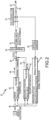
- an embodiment of a TOW missile system 10 includes a missile 12 and a missile launcher 14 to launch and command guide the missile 12 to a target
- Missile 12 includes a motor 16, a plurality of fins 18 and a fin controller 19 configured to adjust the fins 18 to maneuver the missile in first and second orthogonal directions in a projectile coordinate system.
- Missile 12 is typically provided in a sealed tube 20 that is mounted on the missile launcher 14.
- Missile launcher 14 includes a platform 22 for mounting and launching the missile 12, a sight 24 for placement of cross-hairs on a target, an optical sensor 26 having a field of view (FOV) 28 that includes the cross-hairs, a communication link 30 such as a pair of wires between the missile launcher 14 and the missile 12, a guidance computer 32 for generating the Az and El actuator commands to maneuver the missile 12 towards the cross-hairs when track is valid and to maneuver the missile 12 for recapture when track is lost, and a transmitter 34 for transmitting the actuator commands over the communication link 30. Together components may be referred to as the Tracker.
- the Tracker may be referred to as the Tracker.
- Guidance computer 32 includes a signal processor 36 coupled to sensor 26.
- the signal processor 36 is configured to determine a missile position in the FOV 28 and set a track valid flag equals true if the missile 12 is detected in the FOV 28 and to generate a measured missile position in the FOV 28 and set the track valid flag equals false if the missile 12 is not detected.
- a first summing node 38 forms a difference of the measured missile position and a desired missile position (e.g., missile position command) in the FOV (e.g., the cross-hairs) as an error signal.
- a controller 40 is configured to generate "guidance commands" (step 42) as a new nominal actuator command (e.g., including Az and El components) to use a latest command based on the error signal (step 44) if the track valid flag is true (step 46) and to hold a last valid nominal actuator command (step 48) to place the missile 12 on a straight-line path 49 from a last known position of the missile 12 towards the desired missile position in the FOV 28 if the track valid flag is false (step 46).
- guidance commands step 42
- a new nominal actuator command e.g., including Az and El components
- a recapture module 50 is configured to generate "positions" (step 52) as a delta actuator command based on last positions including an orthogonal component orthogonal 53 to the straight-line path 49 as a next sample of a time-based alternating signal (step 54) if the track valid flag is false (step 56) and a delta actuator command as a sequence of zeroes (step 58) if the track valid flag is true (step 56).
- a second summing node 60 sums the nominal actuator command and the delta actuator command to form a total actuator command.
- Transmitter 34 transmits the total actuator command from the missile launcher 14 over the communication link 30 to the missile 12 in flight to the fin controller 19 to control the plurality of fins 18 to command guide the missile 12 to maneuver in the first and second orthogonal directions to flying along an alternating path 62 back and forth across the straight-line path 49 to increase an area of missile motion relative to the tracker's FOV 28 until the missile 12 re-enters the tracker's FOV 28 and valid track is re-established or an abort command is issued.
- Increasing the area of missile motion relative to the tracker's FOV 28 as compared to the area for a straight-line path increases the likelihood of intersecting the tracker's FOV 28.
- the recapture module 50 generates at least an orthogonal component 80 as a time-based alternating signal (e.g., sine wave, triangle etc.) and possibly an inline component 82 in a tracker coordinate system to define a generic search area 84.
- the recapture module 50 uses an angle theta 86 between a straight-line path 88 in the tracker coordinate system defined by the last valid actuator command and an Azimuth axis 94 to transforms the orthogonal and inline components 80, 82 into Az and El components 90, 92, respectively, in a projectile coordinate system.
- the orthogonal and inline components 80, 82 and generic search area 84 are independent of the straight-line path 88.
- the Az and El components 90, 92 are a function of both the orthogonal and inline components 80, 82 and the straight-line path 88.
- angle theta 86 is defined as the angle between inline component 82 (straight-line path 88) and the Azimuth axis 94.
- inline and orthogonal components 100, 102 form a delta actuator command 104 that defines a generic search area 106 in a tracker coordinate system.
- orthogonal component 102 is a time-based sine wave of increasing amplitude that defines the basic form of search area 106.
- a bias term may be added to the time-based sine wave to shape the area of vehicle motion.
- the bias term may include a ramp or exponential function of time.
- Inline component 100 represents an additional component to the last valid (and held) command that defines the straight-line path and is optional.
- inline component 100 may include a constant term 108 or 110, a ramp 112 or an exponential function of time to control the rate of motion of the missile 12 along the straight-line path.
- delta actuator command 104 hence the search area 106 changes as a function of the inline component 100.
- the inline and orthogonal components 100, 102 may be selected as a function of at least one of an elapsed time of travel, a range to a target, a vehicle velocity, the straight-line path and an elapsed time since the last valid track. Selection may be affected by such factors as the energy efficiency of the resulting path or the ability of the missile 12 to reach the target.
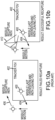
- a missile 200 leaves the tracker's FOV 202 following a path 204 horizontally to the left and undergoes no motion following the loss of track prior to execution of the recapture maneuver.
- the last actuator command is held to place the missile on a straight-line path 206 back towards the expected location of the desired position in the tracker's FOV 202.
- a delta actuator command that follows a time-based alternating signal of increasing amplitude is added to the last actuator command (held) to place the missile on an alternating path 212 about straight-line path 206 back towards the expected location of the desired position in the tracker's FOV 202.
- the last actuator command includes an Az component 214 that moves the missile 200 to the right and an El component 216 to counteract the effects of gravity. Together these components would place the missile 200 on a straight-line path horizontally to the right back towards the tracker's FOV 202. These components are the same for both the existing and proposed recapture algorithms.
- the delta actuator command includes a ramp inline component 112 and an increasing amplitude sine wave orthogonal component 102. Because theta is zero in this example, the Az component 218 equals the inline component 112 and the El component 220 equals the orthogonal component 102 per the matrix transformation in equation 1.
- a total Az component 222 is the sum of Az components 214 and 218 and a total El component 224 is the sum of El components 216 and 220.
- the existing recapture algorithm follows a straight-line path back towards the tracker's FOV.
- the proposed recapture algorithm increases the search area with respect to the FOV and thus provides a higher likelihood of intersecting the tracker's FOV. In this case because there was no unknown motion of the missile after loss of track, both the existing and proposed recapture algorithms result in a successful recapture.
- a missile 300 leaves a tracker's FOV 302 following a path 304 at an angle theta of 45 degrees to the left and undergoes a clockwise rotation of approximately 90 degrees following the loss of track prior to execution of the recapture maneuver.
- the last valid actuator command is held to place the missile 300 on a straight-line path 306 back towards the expected location of the desired position in the tracker's FOV 302 based on the last valid position of the missile 300, resulting in a failed recapture.
- a delta actuator command that follows a time-based alternating signal of increasing amplitude is added to the last actuator command (held) to place the missile 300 on an alternating path 312 about straight-line path 306 back towards the expected location of the desired position in the tracker's FOV 206, resulting in a successful recapture.
- the Az and El components 318, 320 are a composite of any additional inline component and the orthogonal component.
- the straight-line path provided by the existing recapture algorithm fails to recapture the tracker's FOV eventually producing an abort command.
- the alternating path around the straight-line path provided by the proposed recapture algorithm intersects and successfully recaptures the tracker's FOV.
- a missile 400 leaves the tracker's FOV 402 following a path 404 at an angle theta of 45 degrees to the left and undergoes an abrupt vertical shift following the loss of track prior to execution of the recapture maneuver.
- the last actuator command is held to place the missile 400 on a straight-line path 406 back towards the expected location of the desired position in the tracker's FOV 402 based on the last valid position of the missile 400, resulting in a failed recapture.
- a delta actuator command that follows a time-based alternating signal of increasing amplitude is added to the last actuator command (held) to place the missile on an alternating path 412 about straight-line path 406 back towards the expected location of the desired position in the tracker's FOV 406, resulting in a successful recapture.
- theta is 45 degrees in this example, the Az and El components are a composite of any additional inline component and the orthogonal component.
- the straight-line path provided by the existing recapture algorithm fails to recapture the tracker's FOV eventually producing an abort command.
- the alternating path around the straight-line path provided by the proposed recapture algorithm intersects and successfully recaptures the tracker's FOV.
- the proposed recapture algorithm provides for a more robust recapture of the missile given the possibility of unknown missile motion (e.g., rotation or shift) after track is lost and prior to initiating recapture than the existing straight-line recapture algorithm.
- the penalty is reduced energy efficiency.
Landscapes
- Engineering & Computer Science (AREA)
- Chemical & Material Sciences (AREA)
- General Engineering & Computer Science (AREA)
- Combustion & Propulsion (AREA)
- Physics & Mathematics (AREA)
- General Physics & Mathematics (AREA)
- Remote Sensing (AREA)
- Radar, Positioning & Navigation (AREA)
- Electromagnetism (AREA)
- Aviation & Aerospace Engineering (AREA)
- Automation & Control Theory (AREA)
- Aiming, Guidance, Guns With A Light Source, Armor, Camouflage, And Targets (AREA)
- Control Of Position, Course, Altitude, Or Attitude Of Moving Bodies (AREA)
Claims (15)
- Verfahren zur Wiederaufnahme eines fernverfolgten, befehlsgeführten Fahrzeugs in das Sichtfeld (field-of-view - FOV) eines Verfolgers,wobei das Fahrzeug eine Vielzahl von Aktuatoren beinhaltet, die so konfiguriert ist,dass sie Manöver in einer ersten und einer zweiten orthogonalen Richtung ausführt, wobei es sich bei dem Fahrzeug um ein Luft-, Weltraum-, luftverfolgtes Land- oder luftverfolgtes, seegestütztes Fahrzeug handelt, wobei das Verfahren Folgendes umfasst:bei Verlust einer gültigen Verfolgung des Fahrzeugsa) Halten (48) eines letzten Aktuatorbefehls basierend auf einer letzten gemessenen Fahrzeugposition vor der Unterbrechung der Verfolgung als nominalen Aktuatorbefehl, der das Fahrzeug auf einem geradlinigen Weg von einer letzten bekannten Position des Fahrzeugs in Richtung des FOV des Verfolgers manövriert;b) Erzeugen (54) eines Delta-Aktuatorbefehls, der eine Orthogonalkomponente orthogonal zu dem geradlinigen Weg beinhaltet, als nächsten Abtastwert eines zeitbasierten Wechselsignals;c) Summieren des nominalen Aktuatorbefehls und des Delta-Aktuatorbefehls, um einen Gesamtaktuatorbefehl zu erzeugen;d) Übertragen des Gesamtaktuatorbefehls von dem Fernverfolger an das Fahrzeug zum Steuern der Vielzahl von Aktuatoren zum Befehlsführen des Fahrzeugs zum Manövrieren in der ersten und der zweiten orthogonalen Richtung, um das Fahrzeug entlang eines wechselnden Wegs über den geradlinigen Weg vor und zurück zu bewegen, um einen Bereich der Fahrzeugbewegung relativ zu dem FOV des Verfolgers zu vergrößern; undWiederholen der Schritte a) bis d), bis das Fahrzeug wieder in das FOV des Verfolgers eintritt und eine gültige Verfolgung wiederhergestellt ist oder ein Abbruchbefehl ausgegeben wird.
- Verfahren nach Anspruch 1, wobei die Amplitude des zeitbasierten Wechselsignals mit der Zeit zunimmt.
- Verfahren nach Anspruch 1, wobei das Erzeugen der Orthogonalkomponente ferner das Hinzufügen eines Vorspannungsterms zu dem zeitbasierten Wechselsignal umfasst, um den Bereich der Fahrzeugbewegung zu formen.
- Verfahren nach Anspruch 4, wobei der Vorspannungsterm eine konstante, rampenförmige oder exponentielle Funktion der Zeit beinhaltet.
- Verfahren nach Anspruch 1, wobei das Erzeugen des Delta-Aktuatorbefehls ferner das Erzeugen einer Inline-Komponente inline mit dem geradlinigen Weg beinhaltet, um die Bewegungsgeschwindigkeit des Fahrzeugs entlang des geradlinigen Wegs zu steuern.
- Verfahren nach Anspruch 5, wobei die Inline-Komponente eine konstante, rampenförmige oder exponentielle Funktion der Zeit beinhaltet.
- Verfahren nach Anspruch 5, wobei das Erzeugen des Delta-Aktuatorbefehls das Erzeugen anfänglicher Inline- und Orthogonalkomponenten in einem Verfolger-Koordinatensystem und das Verwenden eines Winkels des geradlinigen Wegs in dem Verfolger-Koordinatensystem zum Umwandeln der anfänglichen Inline- und Orthogonalkomponente in die Inline- und Orthogonalkomponente in einem Projektil-Koordinatensystem umfasst.
- Verfahren nach Anspruch 7, wobei die Inline- und Orthogonalkomponenten in dem Projektil-Koordinatensystem durch Kombinationen von Azimut- und Elevationskomponenten definiert sind, die das Fahrzeug in die erste und zweite orthogonale Richtung bewegen.
- Verfahren nach Anspruch 1, wobei:der Delta-Aktuatorbefehl eine Funktion von mindestens einem von einer verstrichenen Flug-/Fahrzeit, einer Entfernung zu einem Ziel, einer Entfernung von der Abschussvorrichtung, einer Fahrzeuggeschwindigkeit, dem geradlinigen Weg und einer verstrichenen Zeit seit der letzten gültigen Verfolgung ist; oderdie Aktuatoren aerodynamische Steuerflächen, Triebwerke oder Propeller umfassen; oderdie Befehle über eine Kabel-, WIFI-, Funk-, Laser-, optische oder Infrarotverbindung an das Fahrzeug übermittelt werden; oderdie an das Fahrzeug übermittelten Befehle analog, digital oder bang-bang sind; oderbei der Fernverfolgung optische, Infrarot-, Radar- oder Sonarsensoren verwendet werden, um die Fahrzeugposition in dem FOV zu bestimmen.
- Verfahren nach Anspruch 1, wobei das Fahrzeug einen Flugkörper umfasst,wobei der nominale Aktuatorbefehl einen nominalen Aktuatorbefehl in einem Projektil-Koordinatensystem umfasst;wobei das Erzeugen des Delta-Aktuatorbefehls ferner das Erzeugen einer Inline-Komponente inline mit dem geradlinigen Weg umfasst; wobei das Verfahren ferner das Verwenden eines Winkels des geradlinigen Wegs in dem Verfolger-Koordinatensystem umfasst, um den Delta-Aktuatorbefehl in das Projektil-Koordinatensystem umzuwandeln; undwobei das Summieren des nominalen Aktuatorbefehls und des Delta-Aktuatorbefehls das Summieren des nominalen Aktuatorbefehls und des Delta-Aktuatorbefehls in dem Projektil-Koordinatensystem umfasst.
- Fernverfolgtes, befehlsgeführtes Flugkörpersystem (10), Folgendes umfassend:einen Flugkörper (12), der einen Motor und eine Vielzahl von Aktuatoren (18, 19) beinhaltet, die so konfiguriert sind, dass sie den Flugkörper in einer ersten und einer zweiten orthogonalen Richtung in einem Projektil-Koordinatensystem manövrieren; undeine Flugkörper-Abschussvorrichtung (14), umfassend eine Plattform (22) zum Abschießen des Flugkörpers,ein Visier (24) zum Platzieren eines Fadenkreuzes auf einem Ziel;einen Sensor (26) mit einem Verfolger-Sichtfeld (FOV), das das Fadenkreuz beinhaltet;eine Kommunikationsverbindung (30) zwischen der Flugkörper-Abschussvorrichtung und dem Flugkörper; undeinen Führungsrechner (32), beinhaltendeinen Signalprozessor (36), der mit dem Sensor gekoppelt und so konfiguriert ist, dass er ein Flag für eine gültige Verfolgung setzt, wenn der Flugkörper in dem FOV erkannt wird, und eine gemessene Flugkörperposition in dem FOV erzeugt,einen ersten Summierknoten (38), der so konfiguriert ist, dass er eine Differenz der gemessenen Flugkörperposition und einer gewünschten Flugkörperposition in dem FOV als Fehlersignal bildet,eine Steuerung (40), die so konfiguriert ist, dass sie einen neuen nominalen Aktuatorbefehl basierend auf dem Fehlersignal erzeugt, wenn das Flag für eine gültige Verfolgung wahr ist, und einen letzten gültigen nominalen Aktuatorbefehl basierend auf einer letzten gemessenen Flugkörperposition vor der Unterbrechung der Verfolgung hält, um den Flugkörper auf einem geradlinigen Weg von einer letzten bekannten Position des Flugkörpers in Richtung der gewünschten Flugkörperposition in dem FOV zu platzieren, wenn das Flag für eine gültige Verfolgung falsch ist;ein Wiederaufnahmemodul (50), das so konfiguriert ist, dass es einen Delta-Aktuatorbefehl einschließlich einer Orthogonalkomponente orthogonal zu dem geradlinigen Weg als nächsten Abtastwert eines zeitbasierten Wechselsignals erzeugt; undeinen zweiten Summierknoten (60), der so konfiguriert ist, dass er den nominalen Aktuatorbefehl und den Delta-Aktuatorbefehl summiert, um einen Gesamtaktuatorbefehl zu bilden; undeinen Sender (34), der so konfiguriert ist, dass er den Gesamtaktuatorbefehl von der Flugkörper-Abschussvorrichtung über die Kommunikationsverbindung an den Flugkörper im Flug an den Steuerflächenaktuator zum Steuern der Vielzahl von Aktuatoren und Befehlsführen des Flugkörpers zum Manövrieren in der ersten und der zweiten orthogonalen Richtung überträgt, um den Flugkörper entlang eines wechselnden Wegs über den geradlinigen Weg vor und zurück zu bewegen, um einen Bewegungsbereich des Flugkörpers relativ zu dem FOV des Verfolgers zu vergrößern, bis der Flugkörper wieder in das FOV des Verfolgers eintritt und eine gültige Verfolgung wiederhergestellt ist oder ein Abbruchbefehl ausgegeben wird.
- Fernverfolgtes, befehlsgeführtes Flugkörpersystem nach Anspruch 16, wobei die Amplitude des zeitbasierten Wechselsignals mit der Zeit zunimmt.
- Fernverfolgtes, befehlsgeführtes Flugkörpersystem nach Anspruch 11, wobei die Orthogonalkomponente ferner einen Vorspannungsterm zur Formung des Bewegungsbereichs des Flugkörpers beinhaltet.
- Fernverfolgtes, befehlsgeführtes Flugkörpersystem nach Anspruch 11, wobei der Delta-Aktuatorbefehl ferner eine Inline-Komponente inline mit dem geradlinigen Weg beinhaltet, um die Bewegungsgeschwindigkeit des Flugkörpers entlang des geradlinigen Wegs zu steuern.
- Fernverfolgtes, befehlsgeführtes Flugkörpersystem nach Anspruch 11, wobei das Wiederaufnahmemodul den Delta-Aktuatorbefehl durch Erzeugen einer anfänglichen Orthogonalkomponente in einem Verfolger-Koordinatensystem und durch Verwenden eines Winkels des geradlinigen Wegs in dem Verfolger-Koordinatensystem zum Umwandeln der Orthogonalkomponente in die Orthogonalkomponente in einem Projektil-Koordinatensystem erzeugt.
Applications Claiming Priority (2)
| Application Number | Priority Date | Filing Date | Title |
|---|---|---|---|
| US15/621,484 US10429151B2 (en) | 2017-06-13 | 2017-06-13 | Recapture of remotely-tracked command guided vehicle into the tracker's field-of-view |
| PCT/US2018/025227 WO2018231320A1 (en) | 2017-06-13 | 2018-03-29 | Recapture of remotely-tracked command guided vehicle into the tracker's field-of-view |
Publications (2)
| Publication Number | Publication Date |
|---|---|
| EP3596420A1 EP3596420A1 (de) | 2020-01-22 |
| EP3596420B1 true EP3596420B1 (de) | 2024-10-09 |
Family
ID=62063180
Family Applications (1)
| Application Number | Title | Priority Date | Filing Date |
|---|---|---|---|
| EP18720444.1A Active EP3596420B1 (de) | 2017-06-13 | 2018-03-29 | Wiederaufnahme eines fernverfolgten, befehlsgeführten fahrzeugs in das sichtfeld des verfolgers |
Country Status (7)
| Country | Link |
|---|---|
| US (1) | US10429151B2 (de) |
| EP (1) | EP3596420B1 (de) |
| KR (1) | KR102242124B1 (de) |
| IL (1) | IL269053B (de) |
| SA (1) | SA519410278B1 (de) |
| WO (1) | WO2018231320A1 (de) |
| ZA (1) | ZA201907232B (de) |
Families Citing this family (1)
| Publication number | Priority date | Publication date | Assignee | Title |
|---|---|---|---|---|
| JP2021033447A (ja) * | 2019-08-20 | 2021-03-01 | ソニー株式会社 | 移動装置、移動体制御システム、および移動体制御方法、並びにプログラム |
Family Cites Families (14)
| Publication number | Priority date | Publication date | Assignee | Title |
|---|---|---|---|---|
| US3708139A (en) * | 1959-01-19 | 1973-01-02 | Us Navy | Missile control system |
| NL132546C (de) | 1961-11-06 | |||
| US3598344A (en) * | 1964-06-01 | 1971-08-10 | Philco Ford Corp | Missile command system |
| US3567163A (en) * | 1964-10-08 | 1971-03-02 | Martin Marietta Corp | Guidance system |
| US3603686A (en) * | 1969-06-04 | 1971-09-07 | Nasa | Acquisition and tracking system for optical radar |
| US3711046A (en) | 1969-10-22 | 1973-01-16 | H Barhydt | Automatic missile guidance system |
| GB1605342A (en) | 1969-11-13 | 1992-01-02 | British Aerospace | Improvements relating to missile guidance systems |
| US4019422A (en) | 1976-07-19 | 1977-04-26 | Paccar Inc. | Vehicular mounted tow missile system |
| US4406429A (en) | 1978-04-13 | 1983-09-27 | Texas Instruments Incorporated | Missile detecting and tracking unit |
| US4666103A (en) | 1980-02-04 | 1987-05-19 | Allen John B | Carrier tracking system |
| US4474343A (en) | 1981-05-04 | 1984-10-02 | Hughes Aircraft Company | Jitter compensating scene stabilizing missile guidance system |
| IL78757A0 (en) | 1986-05-12 | 1986-08-31 | Israel State | Launcher for an optically guided,wire-controlled missile with improved electronic circuitry |
| US5074491A (en) * | 1990-08-14 | 1991-12-24 | Hughes Aircraft Company | Method for correcting misalignment between multiple missile track links |
| CA2161045A1 (en) * | 1994-11-15 | 1996-05-16 | Michael L. Wells | Error detector apparatus with digital coordinate transformation |
-
2017
- 2017-06-13 US US15/621,484 patent/US10429151B2/en active Active
-
2018
- 2018-03-29 KR KR1020197029593A patent/KR102242124B1/ko active Active
- 2018-03-29 WO PCT/US2018/025227 patent/WO2018231320A1/en not_active Ceased
- 2018-03-29 EP EP18720444.1A patent/EP3596420B1/de active Active
-
2019
- 2019-09-01 IL IL269053A patent/IL269053B/en active IP Right Grant
- 2019-10-09 SA SA519410278A patent/SA519410278B1/ar unknown
- 2019-10-30 ZA ZA2019/07232A patent/ZA201907232B/en unknown
Also Published As
| Publication number | Publication date |
|---|---|
| US10429151B2 (en) | 2019-10-01 |
| KR102242124B1 (ko) | 2021-04-19 |
| EP3596420A1 (de) | 2020-01-22 |
| WO2018231320A1 (en) | 2018-12-20 |
| US20180356189A1 (en) | 2018-12-13 |
| IL269053A (en) | 2019-10-31 |
| IL269053B (en) | 2020-04-30 |
| KR20190135009A (ko) | 2019-12-05 |
| SA519410278B1 (ar) | 2022-03-06 |
| ZA201907232B (en) | 2021-06-30 |
Similar Documents
| Publication | Publication Date | Title |
|---|---|---|
| US4008869A (en) | Predicted - corrected projectile control system | |
| US5123327A (en) | Automatic turret tracking apparatus for a light air defense system | |
| US6209820B1 (en) | System for destroying ballistic missiles | |
| EP1366334B1 (de) | Präzisionsgeführtes hypersonisches projektil-waffensystem | |
| EP0736166B1 (de) | Integrierte feuer- und flugsteuerung für hubschrauber mit einem leitsystem vor und nach dem abschuss | |
| EP2529174B1 (de) | System und verfahren zur verfolgung und führung mehrerer objekte | |
| RU2399854C1 (ru) | Способ наведения многоцелевого высокоточного оружия дальней зоны и устройство для его осуществления | |
| US4198015A (en) | Ideal trajectory shaping for anti-armor missiles via time optimal controller autopilot | |
| RU2584210C1 (ru) | Способ стрельбы управляемым снарядом с лазерной полуактивной головкой самонаведения | |
| IL117589A (en) | Air-to-air missile guidance system | |
| AU2016432331B2 (en) | Guided munition systems for detecting off-axis targets | |
| JP2002519619A (ja) | 遠隔制御によって地表付近の標的及び/又は地面に固定された標的を排撃するための方法 | |
| EP0105918B1 (de) | Abschusssystem für endphasengelenkte geschosse | |
| EP3047228B1 (de) | Bildgestützte beleuchtungsanordnung und verfahren | |
| EP3596420B1 (de) | Wiederaufnahme eines fernverfolgten, befehlsgeführten fahrzeugs in das sichtfeld des verfolgers | |
| JP3545709B2 (ja) | 高い正確度の長距離光援助慣性誘導型ミサイル | |
| RU2148236C1 (ru) | Способ наведения ракеты на цель | |
| RU2460963C2 (ru) | Способ наведения ракеты, управляемой лучом радиолокационной станции, и устройство для его осуществления | |
| Palumbo | Guest editor’s introduction: homing missile guidance and control | |
| US20060049300A1 (en) | Missile steering using laser scattering by atmosphere | |
| US5430449A (en) | Missile operable by either air or ground launching | |
| EP3205973B1 (de) | Flugkörper zur verwendung in einem führungssystem eines laserstrahlgelenkten flugkörpers | |
| RU2741133C1 (ru) | Способ поражения летящего переменным курсом и высотой объекта | |
| GB2279444A (en) | Missile guidance system | |
| RU2483272C2 (ru) | Способ определения параметров начальных условий нелинейной траектории воздушной цели |
Legal Events
| Date | Code | Title | Description |
|---|---|---|---|
| STAA | Information on the status of an ep patent application or granted ep patent |
Free format text: STATUS: UNKNOWN |
|
| STAA | Information on the status of an ep patent application or granted ep patent |
Free format text: STATUS: THE INTERNATIONAL PUBLICATION HAS BEEN MADE |
|
| PUAI | Public reference made under article 153(3) epc to a published international application that has entered the european phase |
Free format text: ORIGINAL CODE: 0009012 |
|
| STAA | Information on the status of an ep patent application or granted ep patent |
Free format text: STATUS: REQUEST FOR EXAMINATION WAS MADE |
|
| 17P | Request for examination filed |
Effective date: 20191014 |
|
| AK | Designated contracting states |
Kind code of ref document: A1 Designated state(s): AL AT BE BG CH CY CZ DE DK EE ES FI FR GB GR HR HU IE IS IT LI LT LU LV MC MK MT NL NO PL PT RO RS SE SI SK SM TR |
|
| AX | Request for extension of the european patent |
Extension state: BA ME |
|
| DAV | Request for validation of the european patent (deleted) | ||
| DAX | Request for extension of the european patent (deleted) | ||
| STAA | Information on the status of an ep patent application or granted ep patent |
Free format text: STATUS: EXAMINATION IS IN PROGRESS |
|
| 17Q | First examination report despatched |
Effective date: 20211021 |
|
| GRAP | Despatch of communication of intention to grant a patent |
Free format text: ORIGINAL CODE: EPIDOSNIGR1 |
|
| STAA | Information on the status of an ep patent application or granted ep patent |
Free format text: STATUS: GRANT OF PATENT IS INTENDED |
|
| INTG | Intention to grant announced |
Effective date: 20240502 |
|
| GRAS | Grant fee paid |
Free format text: ORIGINAL CODE: EPIDOSNIGR3 |
|
| GRAA | (expected) grant |
Free format text: ORIGINAL CODE: 0009210 |
|
| STAA | Information on the status of an ep patent application or granted ep patent |
Free format text: STATUS: THE PATENT HAS BEEN GRANTED |
|
| AK | Designated contracting states |
Kind code of ref document: B1 Designated state(s): AL AT BE BG CH CY CZ DE DK EE ES FI FR GB GR HR HU IE IS IT LI LT LU LV MC MK MT NL NO PL PT RO RS SE SI SK SM TR |
|
| REG | Reference to a national code |
Ref country code: CH Ref legal event code: EP |
|
| REG | Reference to a national code |
Ref country code: DE Ref legal event code: R096 Ref document number: 602018075161 Country of ref document: DE |
|
| REG | Reference to a national code |
Ref country code: IE Ref legal event code: FG4D |
|
| REG | Reference to a national code |
Ref country code: LT Ref legal event code: MG9D |
|
| REG | Reference to a national code |
Ref country code: NL Ref legal event code: MP Effective date: 20241009 |
|
| REG | Reference to a national code |
Ref country code: AT Ref legal event code: MK05 Ref document number: 1730998 Country of ref document: AT Kind code of ref document: T Effective date: 20241009 |
|
| PG25 | Lapsed in a contracting state [announced via postgrant information from national office to epo] |
Ref country code: NL Free format text: LAPSE BECAUSE OF FAILURE TO SUBMIT A TRANSLATION OF THE DESCRIPTION OR TO PAY THE FEE WITHIN THE PRESCRIBED TIME-LIMIT Effective date: 20241009 |
|
| PG25 | Lapsed in a contracting state [announced via postgrant information from national office to epo] |
Ref country code: NL Free format text: LAPSE BECAUSE OF FAILURE TO SUBMIT A TRANSLATION OF THE DESCRIPTION OR TO PAY THE FEE WITHIN THE PRESCRIBED TIME-LIMIT Effective date: 20241009 |
|
| PG25 | Lapsed in a contracting state [announced via postgrant information from national office to epo] |
Ref country code: IS Free format text: LAPSE BECAUSE OF FAILURE TO SUBMIT A TRANSLATION OF THE DESCRIPTION OR TO PAY THE FEE WITHIN THE PRESCRIBED TIME-LIMIT Effective date: 20250209 Ref country code: PT Free format text: LAPSE BECAUSE OF FAILURE TO SUBMIT A TRANSLATION OF THE DESCRIPTION OR TO PAY THE FEE WITHIN THE PRESCRIBED TIME-LIMIT Effective date: 20250210 Ref country code: HR Free format text: LAPSE BECAUSE OF FAILURE TO SUBMIT A TRANSLATION OF THE DESCRIPTION OR TO PAY THE FEE WITHIN THE PRESCRIBED TIME-LIMIT Effective date: 20241009 |
|
| PG25 | Lapsed in a contracting state [announced via postgrant information from national office to epo] |
Ref country code: FI Free format text: LAPSE BECAUSE OF FAILURE TO SUBMIT A TRANSLATION OF THE DESCRIPTION OR TO PAY THE FEE WITHIN THE PRESCRIBED TIME-LIMIT Effective date: 20241009 |
|
| PG25 | Lapsed in a contracting state [announced via postgrant information from national office to epo] |
Ref country code: BG Free format text: LAPSE BECAUSE OF FAILURE TO SUBMIT A TRANSLATION OF THE DESCRIPTION OR TO PAY THE FEE WITHIN THE PRESCRIBED TIME-LIMIT Effective date: 20241009 |
|
| PG25 | Lapsed in a contracting state [announced via postgrant information from national office to epo] |
Ref country code: ES Free format text: LAPSE BECAUSE OF FAILURE TO SUBMIT A TRANSLATION OF THE DESCRIPTION OR TO PAY THE FEE WITHIN THE PRESCRIBED TIME-LIMIT Effective date: 20241009 |
|
| PG25 | Lapsed in a contracting state [announced via postgrant information from national office to epo] |
Ref country code: NO Free format text: LAPSE BECAUSE OF FAILURE TO SUBMIT A TRANSLATION OF THE DESCRIPTION OR TO PAY THE FEE WITHIN THE PRESCRIBED TIME-LIMIT Effective date: 20250109 |
|
| PG25 | Lapsed in a contracting state [announced via postgrant information from national office to epo] |
Ref country code: LV Free format text: LAPSE BECAUSE OF FAILURE TO SUBMIT A TRANSLATION OF THE DESCRIPTION OR TO PAY THE FEE WITHIN THE PRESCRIBED TIME-LIMIT Effective date: 20241009 Ref country code: GR Free format text: LAPSE BECAUSE OF FAILURE TO SUBMIT A TRANSLATION OF THE DESCRIPTION OR TO PAY THE FEE WITHIN THE PRESCRIBED TIME-LIMIT Effective date: 20250110 Ref country code: AT Free format text: LAPSE BECAUSE OF FAILURE TO SUBMIT A TRANSLATION OF THE DESCRIPTION OR TO PAY THE FEE WITHIN THE PRESCRIBED TIME-LIMIT Effective date: 20241009 |
|
| PG25 | Lapsed in a contracting state [announced via postgrant information from national office to epo] |
Ref country code: PL Free format text: LAPSE BECAUSE OF FAILURE TO SUBMIT A TRANSLATION OF THE DESCRIPTION OR TO PAY THE FEE WITHIN THE PRESCRIBED TIME-LIMIT Effective date: 20241009 |
|
| PG25 | Lapsed in a contracting state [announced via postgrant information from national office to epo] |
Ref country code: RS Free format text: LAPSE BECAUSE OF FAILURE TO SUBMIT A TRANSLATION OF THE DESCRIPTION OR TO PAY THE FEE WITHIN THE PRESCRIBED TIME-LIMIT Effective date: 20250109 |
|
| PG25 | Lapsed in a contracting state [announced via postgrant information from national office to epo] |
Ref country code: SM Free format text: LAPSE BECAUSE OF FAILURE TO SUBMIT A TRANSLATION OF THE DESCRIPTION OR TO PAY THE FEE WITHIN THE PRESCRIBED TIME-LIMIT Effective date: 20241009 |
|
| PG25 | Lapsed in a contracting state [announced via postgrant information from national office to epo] |
Ref country code: DK Free format text: LAPSE BECAUSE OF FAILURE TO SUBMIT A TRANSLATION OF THE DESCRIPTION OR TO PAY THE FEE WITHIN THE PRESCRIBED TIME-LIMIT Effective date: 20241009 |
|
| REG | Reference to a national code |
Ref country code: DE Ref legal event code: R097 Ref document number: 602018075161 Country of ref document: DE |
|
| PG25 | Lapsed in a contracting state [announced via postgrant information from national office to epo] |
Ref country code: EE Free format text: LAPSE BECAUSE OF FAILURE TO SUBMIT A TRANSLATION OF THE DESCRIPTION OR TO PAY THE FEE WITHIN THE PRESCRIBED TIME-LIMIT Effective date: 20241009 |
|
| PG25 | Lapsed in a contracting state [announced via postgrant information from national office to epo] |
Ref country code: RO Free format text: LAPSE BECAUSE OF FAILURE TO SUBMIT A TRANSLATION OF THE DESCRIPTION OR TO PAY THE FEE WITHIN THE PRESCRIBED TIME-LIMIT Effective date: 20241009 |
|
| PG25 | Lapsed in a contracting state [announced via postgrant information from national office to epo] |
Ref country code: SK Free format text: LAPSE BECAUSE OF FAILURE TO SUBMIT A TRANSLATION OF THE DESCRIPTION OR TO PAY THE FEE WITHIN THE PRESCRIBED TIME-LIMIT Effective date: 20241009 |
|
| PG25 | Lapsed in a contracting state [announced via postgrant information from national office to epo] |
Ref country code: CZ Free format text: LAPSE BECAUSE OF FAILURE TO SUBMIT A TRANSLATION OF THE DESCRIPTION OR TO PAY THE FEE WITHIN THE PRESCRIBED TIME-LIMIT Effective date: 20241009 |
|
| PG25 | Lapsed in a contracting state [announced via postgrant information from national office to epo] |
Ref country code: IT Free format text: LAPSE BECAUSE OF FAILURE TO SUBMIT A TRANSLATION OF THE DESCRIPTION OR TO PAY THE FEE WITHIN THE PRESCRIBED TIME-LIMIT Effective date: 20241009 |
|
| PLBE | No opposition filed within time limit |
Free format text: ORIGINAL CODE: 0009261 |
|
| STAA | Information on the status of an ep patent application or granted ep patent |
Free format text: STATUS: NO OPPOSITION FILED WITHIN TIME LIMIT |
|
| PG25 | Lapsed in a contracting state [announced via postgrant information from national office to epo] |
Ref country code: SE Free format text: LAPSE BECAUSE OF FAILURE TO SUBMIT A TRANSLATION OF THE DESCRIPTION OR TO PAY THE FEE WITHIN THE PRESCRIBED TIME-LIMIT Effective date: 20241009 |
|
| 26N | No opposition filed |
Effective date: 20250710 |
|
| PG25 | Lapsed in a contracting state [announced via postgrant information from national office to epo] |
Ref country code: MC Free format text: LAPSE BECAUSE OF FAILURE TO SUBMIT A TRANSLATION OF THE DESCRIPTION OR TO PAY THE FEE WITHIN THE PRESCRIBED TIME-LIMIT Effective date: 20241009 |
|
| REG | Reference to a national code |
Ref country code: CH Ref legal event code: H13 Free format text: ST27 STATUS EVENT CODE: U-0-0-H10-H13 (AS PROVIDED BY THE NATIONAL OFFICE) Effective date: 20251023 |
|
| PG25 | Lapsed in a contracting state [announced via postgrant information from national office to epo] |
Ref country code: LU Free format text: LAPSE BECAUSE OF NON-PAYMENT OF DUE FEES Effective date: 20250329 |
|
| REG | Reference to a national code |
Ref country code: BE Ref legal event code: MM Effective date: 20250331 |
|
| PG25 | Lapsed in a contracting state [announced via postgrant information from national office to epo] |
Ref country code: BE Free format text: LAPSE BECAUSE OF NON-PAYMENT OF DUE FEES Effective date: 20250331 |
|
| PG25 | Lapsed in a contracting state [announced via postgrant information from national office to epo] |
Ref country code: CH Free format text: LAPSE BECAUSE OF NON-PAYMENT OF DUE FEES Effective date: 20250331 |
|
| PG25 | Lapsed in a contracting state [announced via postgrant information from national office to epo] |
Ref country code: IE Free format text: LAPSE BECAUSE OF NON-PAYMENT OF DUE FEES Effective date: 20250329 |
|
| PGFP | Annual fee paid to national office [announced via postgrant information from national office to epo] |
Ref country code: GB Payment date: 20260219 Year of fee payment: 9 |
|
| PGFP | Annual fee paid to national office [announced via postgrant information from national office to epo] |
Ref country code: DE Payment date: 20260219 Year of fee payment: 9 |
|
| PGFP | Annual fee paid to national office [announced via postgrant information from national office to epo] |
Ref country code: FR Payment date: 20260219 Year of fee payment: 9 |