EP3596414B1 - Installation de liquéfaction de gaz naturel disposée en surface d'une étendue d'eau, et procédé de refroidissement associé - Google Patents
Installation de liquéfaction de gaz naturel disposée en surface d'une étendue d'eau, et procédé de refroidissement associé Download PDFInfo
- Publication number
- EP3596414B1 EP3596414B1 EP18716123.7A EP18716123A EP3596414B1 EP 3596414 B1 EP3596414 B1 EP 3596414B1 EP 18716123 A EP18716123 A EP 18716123A EP 3596414 B1 EP3596414 B1 EP 3596414B1
- Authority
- EP
- European Patent Office
- Prior art keywords
- water
- tubes
- tube bundle
- installation
- heat exchanger
- Prior art date
- Legal status (The legal status is an assumption and is not a legal conclusion. Google has not performed a legal analysis and makes no representation as to the accuracy of the status listed.)
- Active
Links
Images


Classifications
-
- F—MECHANICAL ENGINEERING; LIGHTING; HEATING; WEAPONS; BLASTING
- F28—HEAT EXCHANGE IN GENERAL
- F28B—STEAM OR VAPOUR CONDENSERS
- F28B1/00—Condensers in which the steam or vapour is separate from the cooling medium by walls, e.g. surface condenser
- F28B1/06—Condensers in which the steam or vapour is separate from the cooling medium by walls, e.g. surface condenser using air or other gas as the cooling medium
-
- F—MECHANICAL ENGINEERING; LIGHTING; HEATING; WEAPONS; BLASTING
- F02—COMBUSTION ENGINES; HOT-GAS OR COMBUSTION-PRODUCT ENGINE PLANTS
- F02C—GAS-TURBINE PLANTS; AIR INTAKES FOR JET-PROPULSION PLANTS; CONTROLLING FUEL SUPPLY IN AIR-BREATHING JET-PROPULSION PLANTS
- F02C3/00—Gas-turbine plants characterised by the use of combustion products as the working fluid
- F02C3/20—Gas-turbine plants characterised by the use of combustion products as the working fluid using a special fuel, oxidant, or dilution fluid to generate the combustion products
- F02C3/30—Adding water, steam or other fluids for influencing combustion, e.g. to obtain cleaner exhaust gases
- F02C3/305—Increasing the power, speed, torque or efficiency of a gas turbine or the thrust of a turbojet engine by injecting or adding water, steam or other fluids
-
- F—MECHANICAL ENGINEERING; LIGHTING; HEATING; WEAPONS; BLASTING
- F25—REFRIGERATION OR COOLING; COMBINED HEATING AND REFRIGERATION SYSTEMS; HEAT PUMP SYSTEMS; MANUFACTURE OR STORAGE OF ICE; LIQUEFACTION SOLIDIFICATION OF GASES
- F25B—REFRIGERATION MACHINES, PLANTS OR SYSTEMS; COMBINED HEATING AND REFRIGERATION SYSTEMS; HEAT PUMP SYSTEMS
- F25B11/00—Compression machines, plants or systems, using turbines, e.g. gas turbines
-
- F—MECHANICAL ENGINEERING; LIGHTING; HEATING; WEAPONS; BLASTING
- F25—REFRIGERATION OR COOLING; COMBINED HEATING AND REFRIGERATION SYSTEMS; HEAT PUMP SYSTEMS; MANUFACTURE OR STORAGE OF ICE; LIQUEFACTION SOLIDIFICATION OF GASES
- F25J—LIQUEFACTION, SOLIDIFICATION OR SEPARATION OF GASES OR GASEOUS OR LIQUEFIED GASEOUS MIXTURES BY PRESSURE AND COLD TREATMENT OR BY BRINGING THEM INTO THE SUPERCRITICAL STATE
- F25J1/00—Processes or apparatus for liquefying or solidifying gases or gaseous mixtures
- F25J1/0002—Processes or apparatus for liquefying or solidifying gases or gaseous mixtures characterised by the fluid to be liquefied
- F25J1/0022—Hydrocarbons, e.g. natural gas
-
- F—MECHANICAL ENGINEERING; LIGHTING; HEATING; WEAPONS; BLASTING
- F25—REFRIGERATION OR COOLING; COMBINED HEATING AND REFRIGERATION SYSTEMS; HEAT PUMP SYSTEMS; MANUFACTURE OR STORAGE OF ICE; LIQUEFACTION SOLIDIFICATION OF GASES
- F25J—LIQUEFACTION, SOLIDIFICATION OR SEPARATION OF GASES OR GASEOUS OR LIQUEFIED GASEOUS MIXTURES BY PRESSURE AND COLD TREATMENT OR BY BRINGING THEM INTO THE SUPERCRITICAL STATE
- F25J1/00—Processes or apparatus for liquefying or solidifying gases or gaseous mixtures
- F25J1/003—Processes or apparatus for liquefying or solidifying gases or gaseous mixtures characterised by the kind of cold generation within the liquefaction unit for compensating heat leaks and liquid production
- F25J1/0047—Processes or apparatus for liquefying or solidifying gases or gaseous mixtures characterised by the kind of cold generation within the liquefaction unit for compensating heat leaks and liquid production using an "external" refrigerant stream in a closed vapor compression cycle
- F25J1/0052—Processes or apparatus for liquefying or solidifying gases or gaseous mixtures characterised by the kind of cold generation within the liquefaction unit for compensating heat leaks and liquid production using an "external" refrigerant stream in a closed vapor compression cycle by vaporising a liquid refrigerant stream
-
- F—MECHANICAL ENGINEERING; LIGHTING; HEATING; WEAPONS; BLASTING
- F25—REFRIGERATION OR COOLING; COMBINED HEATING AND REFRIGERATION SYSTEMS; HEAT PUMP SYSTEMS; MANUFACTURE OR STORAGE OF ICE; LIQUEFACTION SOLIDIFICATION OF GASES
- F25J—LIQUEFACTION, SOLIDIFICATION OR SEPARATION OF GASES OR GASEOUS OR LIQUEFIED GASEOUS MIXTURES BY PRESSURE AND COLD TREATMENT OR BY BRINGING THEM INTO THE SUPERCRITICAL STATE
- F25J1/00—Processes or apparatus for liquefying or solidifying gases or gaseous mixtures
- F25J1/02—Processes or apparatus for liquefying or solidifying gases or gaseous mixtures requiring the use of refrigeration, e.g. of helium or hydrogen ; Details and kind of the refrigeration system used; Integration with other units or processes; Controlling aspects of the process
- F25J1/0243—Start-up or control of the process; Details of the apparatus used; Details of the refrigerant compression system used
- F25J1/0257—Construction and layout of liquefaction equipments, e.g. valves, machines
- F25J1/0275—Construction and layout of liquefaction equipments, e.g. valves, machines adapted for special use of the liquefaction unit, e.g. portable or transportable devices
- F25J1/0277—Offshore use, e.g. during shipping
- F25J1/0278—Unit being stationary, e.g. on floating barge or fixed platform
-
- F—MECHANICAL ENGINEERING; LIGHTING; HEATING; WEAPONS; BLASTING
- F25—REFRIGERATION OR COOLING; COMBINED HEATING AND REFRIGERATION SYSTEMS; HEAT PUMP SYSTEMS; MANUFACTURE OR STORAGE OF ICE; LIQUEFACTION SOLIDIFICATION OF GASES
- F25J—LIQUEFACTION, SOLIDIFICATION OR SEPARATION OF GASES OR GASEOUS OR LIQUEFIED GASEOUS MIXTURES BY PRESSURE AND COLD TREATMENT OR BY BRINGING THEM INTO THE SUPERCRITICAL STATE
- F25J1/00—Processes or apparatus for liquefying or solidifying gases or gaseous mixtures
- F25J1/02—Processes or apparatus for liquefying or solidifying gases or gaseous mixtures requiring the use of refrigeration, e.g. of helium or hydrogen ; Details and kind of the refrigeration system used; Integration with other units or processes; Controlling aspects of the process
- F25J1/0243—Start-up or control of the process; Details of the apparatus used; Details of the refrigerant compression system used
- F25J1/0279—Compression of refrigerant or internal recycle fluid, e.g. kind of compressor, accumulator, suction drum etc.
- F25J1/0281—Compression of refrigerant or internal recycle fluid, e.g. kind of compressor, accumulator, suction drum etc. characterised by the type of prime driver, e.g. hot gas expander
- F25J1/0283—Gas turbine as the prime mechanical driver
-
- F—MECHANICAL ENGINEERING; LIGHTING; HEATING; WEAPONS; BLASTING
- F25—REFRIGERATION OR COOLING; COMBINED HEATING AND REFRIGERATION SYSTEMS; HEAT PUMP SYSTEMS; MANUFACTURE OR STORAGE OF ICE; LIQUEFACTION SOLIDIFICATION OF GASES
- F25J—LIQUEFACTION, SOLIDIFICATION OR SEPARATION OF GASES OR GASEOUS OR LIQUEFIED GASEOUS MIXTURES BY PRESSURE AND COLD TREATMENT OR BY BRINGING THEM INTO THE SUPERCRITICAL STATE
- F25J1/00—Processes or apparatus for liquefying or solidifying gases or gaseous mixtures
- F25J1/02—Processes or apparatus for liquefying or solidifying gases or gaseous mixtures requiring the use of refrigeration, e.g. of helium or hydrogen ; Details and kind of the refrigeration system used; Integration with other units or processes; Controlling aspects of the process
- F25J1/0243—Start-up or control of the process; Details of the apparatus used; Details of the refrigerant compression system used
- F25J1/0279—Compression of refrigerant or internal recycle fluid, e.g. kind of compressor, accumulator, suction drum etc.
- F25J1/0281—Compression of refrigerant or internal recycle fluid, e.g. kind of compressor, accumulator, suction drum etc. characterised by the type of prime driver, e.g. hot gas expander
- F25J1/0284—Electrical motor as the prime mechanical driver
-
- F—MECHANICAL ENGINEERING; LIGHTING; HEATING; WEAPONS; BLASTING
- F25—REFRIGERATION OR COOLING; COMBINED HEATING AND REFRIGERATION SYSTEMS; HEAT PUMP SYSTEMS; MANUFACTURE OR STORAGE OF ICE; LIQUEFACTION SOLIDIFICATION OF GASES
- F25J—LIQUEFACTION, SOLIDIFICATION OR SEPARATION OF GASES OR GASEOUS OR LIQUEFIED GASEOUS MIXTURES BY PRESSURE AND COLD TREATMENT OR BY BRINGING THEM INTO THE SUPERCRITICAL STATE
- F25J1/00—Processes or apparatus for liquefying or solidifying gases or gaseous mixtures
- F25J1/02—Processes or apparatus for liquefying or solidifying gases or gaseous mixtures requiring the use of refrigeration, e.g. of helium or hydrogen ; Details and kind of the refrigeration system used; Integration with other units or processes; Controlling aspects of the process
- F25J1/0243—Start-up or control of the process; Details of the apparatus used; Details of the refrigerant compression system used
- F25J1/0279—Compression of refrigerant or internal recycle fluid, e.g. kind of compressor, accumulator, suction drum etc.
- F25J1/0296—Removal of the heat of compression, e.g. within an inter- or afterstage-cooler against an ambient heat sink
-
- F—MECHANICAL ENGINEERING; LIGHTING; HEATING; WEAPONS; BLASTING
- F25—REFRIGERATION OR COOLING; COMBINED HEATING AND REFRIGERATION SYSTEMS; HEAT PUMP SYSTEMS; MANUFACTURE OR STORAGE OF ICE; LIQUEFACTION SOLIDIFICATION OF GASES
- F25J—LIQUEFACTION, SOLIDIFICATION OR SEPARATION OF GASES OR GASEOUS OR LIQUEFIED GASEOUS MIXTURES BY PRESSURE AND COLD TREATMENT OR BY BRINGING THEM INTO THE SUPERCRITICAL STATE
- F25J1/00—Processes or apparatus for liquefying or solidifying gases or gaseous mixtures
- F25J1/02—Processes or apparatus for liquefying or solidifying gases or gaseous mixtures requiring the use of refrigeration, e.g. of helium or hydrogen ; Details and kind of the refrigeration system used; Integration with other units or processes; Controlling aspects of the process
- F25J1/0243—Start-up or control of the process; Details of the apparatus used; Details of the refrigerant compression system used
- F25J1/0279—Compression of refrigerant or internal recycle fluid, e.g. kind of compressor, accumulator, suction drum etc.
- F25J1/0296—Removal of the heat of compression, e.g. within an inter- or afterstage-cooler against an ambient heat sink
- F25J1/0297—Removal of the heat of compression, e.g. within an inter- or afterstage-cooler against an ambient heat sink using an externally chilled fluid, e.g. chilled water
-
- F—MECHANICAL ENGINEERING; LIGHTING; HEATING; WEAPONS; BLASTING
- F28—HEAT EXCHANGE IN GENERAL
- F28D—HEAT-EXCHANGE APPARATUS, NOT PROVIDED FOR IN ANOTHER SUBCLASS, IN WHICH THE HEAT-EXCHANGE MEDIA DO NOT COME INTO DIRECT CONTACT
- F28D5/00—Heat-exchange apparatus having stationary conduit assemblies for one heat-exchange medium only, the media being in contact with different sides of the conduit wall, using the cooling effect of natural or forced evaporation
-
- F—MECHANICAL ENGINEERING; LIGHTING; HEATING; WEAPONS; BLASTING
- F28—HEAT EXCHANGE IN GENERAL
- F28F—DETAILS OF HEAT-EXCHANGE AND HEAT-TRANSFER APPARATUS, OF GENERAL APPLICATION
- F28F1/00—Tubular elements; Assemblies of tubular elements
- F28F1/02—Tubular elements of cross-section which is non-circular
- F28F1/06—Tubular elements of cross-section which is non-circular crimped or corrugated in cross-section
-
- F—MECHANICAL ENGINEERING; LIGHTING; HEATING; WEAPONS; BLASTING
- F05—INDEXING SCHEMES RELATING TO ENGINES OR PUMPS IN VARIOUS SUBCLASSES OF CLASSES F01-F04
- F05D—INDEXING SCHEME FOR ASPECTS RELATING TO NON-POSITIVE-DISPLACEMENT MACHINES OR ENGINES, GAS-TURBINES OR JET-PROPULSION PLANTS
- F05D2240/00—Components
- F05D2240/90—Mounting on supporting structures or systems
-
- F—MECHANICAL ENGINEERING; LIGHTING; HEATING; WEAPONS; BLASTING
- F25—REFRIGERATION OR COOLING; COMBINED HEATING AND REFRIGERATION SYSTEMS; HEAT PUMP SYSTEMS; MANUFACTURE OR STORAGE OF ICE; LIQUEFACTION SOLIDIFICATION OF GASES
- F25J—LIQUEFACTION, SOLIDIFICATION OR SEPARATION OF GASES OR GASEOUS OR LIQUEFIED GASEOUS MIXTURES BY PRESSURE AND COLD TREATMENT OR BY BRINGING THEM INTO THE SUPERCRITICAL STATE
- F25J2240/00—Processes or apparatus involving steps for expanding of process streams
- F25J2240/80—Hot exhaust gas turbine combustion engine
-
- Y—GENERAL TAGGING OF NEW TECHNOLOGICAL DEVELOPMENTS; GENERAL TAGGING OF CROSS-SECTIONAL TECHNOLOGIES SPANNING OVER SEVERAL SECTIONS OF THE IPC; TECHNICAL SUBJECTS COVERED BY FORMER USPC CROSS-REFERENCE ART COLLECTIONS [XRACs] AND DIGESTS
- Y02—TECHNOLOGIES OR APPLICATIONS FOR MITIGATION OR ADAPTATION AGAINST CLIMATE CHANGE
- Y02A—TECHNOLOGIES FOR ADAPTATION TO CLIMATE CHANGE
- Y02A20/00—Water conservation; Efficient water supply; Efficient water use
- Y02A20/124—Water desalination
Definitions
- the present invention relates to a natural gas liquefaction installation according to the preamble of claim 1.
- Such an installation is intended in particular to liquefy natural gas produced from a reservoir located under a body of water, or on land, and which is conveyed to the installation.
- the installation is advantageously a floating installation on the body of water, such as a platform or a barge carrying a natural gas liquefaction unit, designated by the English term "Floating Liquefied Natural Gas” or "FLNG”. .
- Such an installation is intended in particular to produce natural gas, to liquefy the natural gas produced, then to store and/or transfer the liquefied natural gas to an LNG carrier or other transport barge. This simplifies the transport of gas to the places of consumption, by reducing the volume transported. In addition, the layout of the installations at sea removes the risks associated with such an installation from inhabited areas and reduces the impact on the environment.
- the liquefaction units reject a large quantity of heat into the surrounding medium, in practice into the air or into the water.
- a water circulation cooling network on exchangers or air cooling are not entirely satisfactory, because the space available on a floating installation is reduced compared to a liquefaction unit similar to earth.
- the installation's liquefaction capacity is therefore limited to accommodate all the equipment on the floating installation.
- the heated water produced in large quantities by the installation must be discharged into the body of water, which can have an impact on the environment.
- Water evaporative cooling is known to be efficient and compact. On land, it is economical to provide a retention basin under the cooling towers and to carry out partial evaporation of water loaded with salts and other dry residues.
- WO2015/140044 which discloses the preamble of claim 1, describes a floating plant for the production of liquefied natural gas, provided with air heat exchangers which are all fed by a centralized air supply pipe arranged at the edge of the hull. This ensures that the air supplied to each of the heat exchangers is fresh air, and not air that has already passed through a heat exchanger.
- water droplets are sprayed at the inlet of the supply duct to cool and humidify the incoming air.
- the water droplets evaporate in the duct and the airflow feeding the heat exchangers is free of liquid droplets.
- US 2016/238312 also describes an installation for the production of liquefied natural gas, equipped with air heat exchangers.
- An object of the invention is to further increase the production capacity of a floating installation for the liquefaction of natural gas, while limiting the size of the installation.
- the invention also relates to a method for cooling a stream according to claim 10.
- the method according to the invention comprises one or more of the characteristics of claims 11 to 14, taken separately or in any technically possible combination.
- upstream and downstream are understood relative to the normal direction of circulation of a flow in a duct.
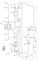
- a first installation 10 for the liquefaction of natural gas according to the invention is illustrated diagrammatically by the figure 1 .
- the installation 10 is intended to be placed on the surface of a body of water 12.
- the expanse of water 12 is for example a sea, a lake or an ocean.
- the depth of the expanse of water 12 to the right of the installation 10 is for example between 15 m and 3000 m.
- Installation 10 is suitable for collecting natural gas from an underground reservoir (not shown).
- the natural gas is produced directly on the installation 10.
- the natural gas is produced on another production unit at the surface of the body of water 12 or on a production unit on land and is conveyed to to facility 10 via a transmission line.
- Installation 10 is advantageously a floating installation.
- the installation 10 is fixed to the bottom of the expanse of water by an immersed structure.
- the installation 10 is a floating natural gas liquefaction unit, designated by the acronym “FLNG” for “Floating Liquefied Natural Gas”.
- the installation 10 comprises a hull 14 floating on the surface of the expanse of water 12, and at least one deck 16 carried by the hull 14.
- the deck 16 is arranged above the surface of the expanse of water 12.
- the installation 10 comprises a natural gas liquefaction unit 18, the relevant parts of which are represented on the figure 1 , and a desalination unit 20 clean water to produce demineralized water from salt water taken from the body of water 12.
- the natural gas liquefaction unit 18 is advantageously arranged on the deck 16 and the desalination assembly 20 is preferably housed in the hull 14.
- the natural gas liquefaction unit 18 comprises at least one air-cooled heat exchanger 22 intended to cool a stream 24 circulating in the unit 18 to produce a cooled stream 25. According to the invention, it comprises a set 26 of projection, into the air-cooled heat exchanger 22, of demineralised water coming from the desalination assembly 20.
- the liquefaction unit 18 also advantageously comprises a secondary assembly 27 for spraying demineralized water into at least one other piece of equipment of the liquefaction unit 18, for example a gas turbine.
- the liquefaction unit 18 comprises a source of natural gas 30 to be cooled, a main heat exchanger 32 for cooling the natural gas coming from the source 30, and a system 34 for liquefying the cooled natural gas coming from the main heat exchanger 32.
- the liquefaction unit 18 further comprises at least one cooling cycle 36 of the main heat exchanger 32, the cooling cycle 36 integrating the air-cooled heat exchanger 22.
- the natural gas source 30 is connected to the natural gas production facility, advantageously via natural gas purification units intended to extract water, heavy compounds (for example C6+ compounds) and sulfur compounds.
- natural gas purification units intended to extract water, heavy compounds (for example C6+ compounds) and sulfur compounds.
- the main heat exchanger 32 is capable of putting the natural gas to be cooled coming from the source 30 into contactless heat exchange relationship with the refrigerant fluid circulating in the cooling cycle 36, in order to lower the temperature of the natural gas.
- the natural gas liquefaction system 34 advantageously comprises at least one expansion member (not shown) for the cooled natural gas. It comprises at least one tank for collecting liquefied natural gas.
- the LNG collection and storage tank is capable of being connected to an LNG carrier or other transport barge to evacuate the liquefied natural gas produced in the liquefaction unit 18.
- the cooling cycle 36 comprises, in the direction of circulation of the refrigerant fluid from the outlet of the main heat exchanger 32, a compressor 40 most often coupled to a gas turbine 42, and the air-cooled heat exchanger 22.
- the cooling cycle 36 further comprises an expansion member 46 of the refrigerant fluid.
- the compressor 40 can also be driven by an electric motor as shown alternatively in the figure 6 .
- the gas turbines for electricity production which can be installed in the hull, can also benefit from water injection improving their performance.
- Compressor 40 is capable of recovering the heated refrigerant fluid coming from main heat exchanger 32 and recompressing it. In this example, it is driven by gas turbine 42.
- the gas turbine 42 comprises a fuel injection 48, a combustion chamber 50 receiving the fuel, an air compressor in the upstream part of the gas turbine 42 and a downstream turbine 52.
- the expansion device 46 is here a static expansion valve.
- the expansion member 46 is a dynamic expansion turbine.
- the expansion device 46 is suitable for expanding and liquefying the cooled stream 60 coming from the intermediate heat exchanger 44 before its introduction into the main heat exchanger 32.
- the air-cooled heat exchanger 22 comprises an envelope 70 defining an internal duct 72 for the circulation of a gas flow along a local axis A-A', extending between an air inlet 77 and an outlet of air 78.
- the air flow entering the envelope through the air inlet 77 is at atmospheric conditions. After passing through the heat exchanger, the air flow extracted by the air outlet 78 has a higher temperature than at the air inlet 77. It is loaded with water vapor and without free water.
- the air-cooled heat exchanger 22 further comprises a bundle of tubes 74 passing through the internal duct 72 to cause the flow to be cooled 24 to circulate through the internal duct 72 and at least one fan 76, capable of carrying out the drive. gas flow through the internal conduit 72 around the tubes of the tube bundle 74.
- the bundle of tubes 74 comprises a plurality of tubes intended to convey the flow to be cooled 24 through the internal duct 72.
- the tubes are suitable for placing the flow to be cooled 24 in heat exchange relation without contact with the gaseous flow circulating in the internal duct.
- the tubes of the tube bundle 74 extend transversely with respect to the circulation axis A-A'. They are arranged parallel to each other at several levels N1 to N2 along the circulation axis A-A'.
- the circulation axis AA' extends vertically.
- the tubes of the tube bundle 74 extend horizontally at several levels N1 to N2 located one above the other along the vertical axis.
- the tubes of the tube bundle 74 exclusively contain the stream 24 to be cooled.
- the tubes can be smooth on their external and/or internal surfaces, or be equipped with improved surfaces in the form of structures or fins worked in the mass of metal or added.
- the propeller of the fan 76 is arranged transversely with respect to the circulation axis A-A'.
- the propeller of the fan 76 is positioned downstream of the bundle of tubes 74, with respect to the direction of flow of the gas at the outlet of the conduit 72 defined by the casing 70.
- the propeller of the fan 76 is arranged upstream of the tube bundle 74 with respect to the direction of gas circulation.
- the propeller of the fan 76 When driven in rotation, the propeller of the fan 76 causes the flow of air circulating in the duct 72, from upstream to downstream around the tubes of the tube bundle 74.
- the propeller of the fan 76 is here arranged above the tubes of the bundle of tubes 74. It is capable of generating a flow of air circulating from bottom to top in the duct 72.
- the spray assembly 26 comprises a plurality of nozzles 80 for spraying demineralized water coming from the desalination assembly 20, directed towards the tubes of the bundle of tubes 74, to spray liquid demineralized water in contact with the tubes of the tube bundle 74.
- the water is projected here in the form of jets from the nozzles 80.
- the jets from the nozzles 80 are projected directly onto the tubes of the tube bundle 74.
- the spray assembly 26 further comprises a pipe 82 for supplying demineralized water to the nozzles 80 and a control unit 84 for the flow of water sprayed by the or each spray nozzle 80 onto the tubes of the tubing 74.
- the spray assembly 26 comprises at least a first ramp 85 of nozzles located opposite a first level of tubes of the bundle of tubes 74, and at least a second ramp 86 of nozzles 80 located opposite a second level tubes of the tube bundle 74 axially offset along the circulation axis AA 'with respect to the first level.
- the distribution of water by the nozzles 80 is staged along the circulation axis A-A'.
- all the nozzles 80 are arranged inside the internal duct 72 defined by the tubular casing 70. Each nozzle 80 is placed directly opposite a tube of the bundle of tubes 74 to spray water directly onto the tubes.
- At least a part of the nozzles 80 emerges between two tubes of the tube bundle 74.
- the nozzles 80 are here directed downwards to generate jets of water falling on the tubes of the tube bundle 74 by gravity.
- the supply line 82 is connected upstream to the desalination assembly 20, to be supplied with demineralised water:
- the control unit 84 comprises at least one flow adjustment valve 90 in the pipe 82 and a control unit 92, suitable for adjusting the flow of water supplied to the nozzles 80 via the flow adjustment valve 90 so that the water from the nozzles 80 which comes into contact in liquid form with the tubes of the tube bundle 74 is completely evaporated, thus avoiding an excess of liquid demineralized water from the water spray assembly 26 downstream of the tube bundle 74.
- the jets of water sprayed by the nozzles 80 are directed exclusively towards the surface of the tubes of the bundle of tubes 74. They are able to reach the surface of the tubes of the bundle of tubes 74 in liquid form, and to evaporate completely there.
- the secondary spray assembly 27 includes at least one secondary spray nozzle 90A opening into the gas turbine 42 and a pipe 92A for supplying demineralized water to the secondary nozzle 90A.
- This intermediate water injection improves the performance of the gas turbine.
- the gas turbine 42 which drives the refrigeration compressor 40 benefits from a power increased by the injection of water.
- the desalination unit 20 comprises a salt water intake intake 100, a desalination unit 102, and a pump 104 upstream of the salt water supply, arranged between the salt water intake intake 100 and the desalination unit 102.
- the desalination assembly 20 further comprises an outlet 106 for discharging brine to the body of water 12 and a pump 108 for discharging demineralized water to the water spray assemblies 26, 27.
- the water intake 100 opens downwards into the expanse of water 12. It is for example connected to a riser (or "riser” in English) as described in one of the French applications FR3036412 Or FR3037343 of the Applicant.
- the desalination unit 102 comprises for example a multi-stage reverse osmosis system, a filtration system and a finishing (polishing in English).
- the brine is suitable for being evacuated through the evacuation outlet 106.
- the demineralized water is suitable for being distributed to the projection assemblies 26, 27 via the pump 108.
- Pump 108 is connected downstream to respective supply lines 82, 92A.
- pressurized natural gas is produced from an underground reservoir, and is piped to source 30 on plant 10.
- the natural gas is conveyed through main heat exchanger 32 to come into contact with heat exchange with a refrigerant circulating in the cooling cycle 36.
- the natural gas is thus cooled, for example to a temperature between -100° C. and -164° C. depending on the quality of the gas and the liquefaction process.
- the natural gas may undergo flash expansion to be liquefied.
- the liquefied natural gas is recovered in a tank before being evacuated via an LNG carrier or a barge.
- the heated refrigerant from the main heat exchanger 32 is fed to the compressor 40 to be compressed there. Then, it is conveyed in the form of a flow to be cooled 24 to the air-cooled heat exchanger 22 to circulate in the tubes of the tube bundle 74.
- the pump 104 of the desalination assembly 20 is activated to pump salt water through the water intake 100 and bring it to the desalination unit 102.
- the salt water is desalinated to produce demineralised water and brine.
- the demineralized water is pumped by pump 108 to supply lines 82, 92A.
- the projection assembly 26 is activated.
- Demineralized water from the desalination assembly 20 is conveyed to each nozzle 80 to generate jets of water which are projected directly onto the tubes of the tube bundle 74.
- the water sprayed on the tubes evaporates on contact with the outer surface of the tubes, generating a cooling thermal power of the flow to be cooled 24 which circulates through the tubes of the tube bundle 74.
- the fan 76 is also activated to generate a circulation of an air flow in the duct 72 along the axis of circulation A-A, making it possible to evacuate the extracted heat.
- the residual water which has not evaporated on a tube of the bundle of tubes 74 gradually evaporates in the pipe 72, in the air which gradually warms up.
- the control unit 84 controls the flow of water circulating through the supply pipe 82 so that at the exit from the bundle of tubes 74, all the water projected by the nozzles 80 has evaporated.
- the optimum flow of water supplied to the nozzles 80 is determined automatically so as to satisfy the temperature setpoint values of the fluid to be cooled or of the cold to be supplied in the case of partial condensation.
- the operating mode of the fan(s) 76 can be associated with this optimization of the water flow.
- the optimum water flow can also be predicted by calculation at any time by the control unit 84 as a function of the physical parameters of the exchanger, the temperature and/or humidity of the ambient air, the flow of air generated by the fan 76 and heat to be evacuated on the process side.
- the number of nozzles in service can be optimized according to the load.
- This flow optimization calculation is based on the heat exchange calculation algorithms that were used to define the equipment.
- the flow to be cooled 24 is cooled in a particularly efficient manner, with an air-cooled heat exchanger 22 which does not require cumbersome water supply piping in the installation 10.
- the compactness of the air cooling heat exchanger 22 is therefore optimal, which increases the space available for the equipment for the production or liquefaction of natural gas.
- the overall capacity of the installation 10 is therefore increased.
- the casing 70 defines a vertical duct 72 opening downwards upstream of the tube bundle 74.
- the design parameters are optimized according to the needs, namely direction of the air flow, number of beams and nozzles, the principle of direct contact of liquid water with the tubes and its total evaporation on the surface being in any case respected.
- the airflow is driven from top to bottom in the duct 72.
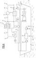
- the cooled flow 25 from the exchanger 22 is conveyed to an intermediate heat exchanger 44 integrated in the cycle to undergo additional cooling, before being expanded in the expansion device 46, to be reintroduced in the main heat exchanger 32. This is shown in the picture 3 .
- the heat exchanger 44 is cooled by sea water from the body of water 12 as shown in the picture 3 .
- the liquefaction unit 18 comprises an additional cooling cycle 120 integrating the intermediate heat exchanger 44 in which the cooling fluid is heated.
- the additional cooling cycle 120 represented on the picture 3 , further comprises a primary heat exchanger 122 intended for cooling the cooling fluid after it has passed through the intermediate heat exchanger 44 and an additional pump 124 capable of pumping the cooling fluid from the additional heat exchanger 44 into the heat exchanger primary thermal 122.
- the primary heat exchanger 122 is also supplied by a pipe 126 for the circulation of salt water coming from the salt water withdrawal intake 100.
- the circulation line 126 is tapped downstream of the pump 104 and upstream of the desalination unit 102. It passes through the heat exchanger 122 to place in contactless heat exchange relationship the sea water recovered by salt water intake 100 and coolant from pump 124.
- the circulation line 126 opens downstream into the body of water 12.
- salt water from body of water 12 is drawn through salt water intake 100 and partially diverted through pump 104 to circulation line 126.
- the salt water heats up by cooling the cooling fluid circulating in the primary heat exchanger 122, before it passes through the intermediate heat exchanger 44.
- the heat exchanger 44 is cooled directly by seawater as shown in the figure 4 And 5 .
- the seawater ensuring the cooling of the exchanger 44 is pumped from the sea supply pipe to the desalination system 102, by the pump 124.
- the seawater circulation pipe opens downstream into the body of water 12.
- the seawater ensuring the refrigeration of the exchanger 44 is pumped from an external pump station independent of the hull, mounted cantilevered on the module comprising the exchanger 44.
Landscapes
- Engineering & Computer Science (AREA)
- Mechanical Engineering (AREA)
- General Engineering & Computer Science (AREA)
- Physics & Mathematics (AREA)
- Thermal Sciences (AREA)
- Chemical & Material Sciences (AREA)
- Chemical Kinetics & Catalysis (AREA)
- General Chemical & Material Sciences (AREA)
- Oil, Petroleum & Natural Gas (AREA)
- Combustion & Propulsion (AREA)
- Ocean & Marine Engineering (AREA)
- Geometry (AREA)
- Separation By Low-Temperature Treatments (AREA)
- Heat-Exchange Devices With Radiators And Conduit Assemblies (AREA)
- Vaporization, Distillation, Condensation, Sublimation, And Cold Traps (AREA)
Description
- La présente invention concerne une installation de liquéfaction de gaz naturel selon le préambule de la revendication 1.
- Une telle installation est destinée notamment à liquéfier du gaz naturel produit à partir d'un réservoir situé sous une étendue d'eau, ou à terre, et qui est convoyé jusqu'à l'installation.
- L'installation est avantageusement une installation flottant sur l'étendue d'eau, telle qu'une plate-forme ou une barge portant une unité de liquéfaction de gaz naturel, désignée par le terme anglais « Floating Liquefied Natural Gas » ou « FLNG ».
- Une telle installation est destinée notamment à produire du gaz naturel, à liquéfier le gaz naturel produit, puis à stocker et/ou à transférer le gaz naturel liquéfié sur un méthanier ou autre barge de transport. Ceci simplifie le transport du gaz vers les lieux de consommation, en réduisant le volume transporté. En outre, la disposition des installations en mer éloigne les risques liés à une telle installation des zones habitées et diminue l'impact sur l'environnement.
- Afin de mettre en oeuvre de manière économique un procédé de liquéfaction de gaz naturel, les unités de liquéfaction rejettent une grande quantité de chaleur dans le milieu environnant, en pratique dans l'air ou dans l'eau.
- De nombreuses unités de liquéfaction de gaz naturel ont été construites à terre depuis les années 1960. Les techniques de refroidissement employées à terre ne donnent pas entièrement satisfaction lorsqu'elles transposées en mer.
- L'avantage d'une installation de liquéfaction de gaz naturel flottant est qu'elle dispose par nature d'une source d'eau de refroidissement en grande quantité et à basse température. Par conséquent, il est connu de faire circuler de l'eau prélevée dans l'étendue d'eau pour le refroidissement des équipements de l'unité de liquéfaction, soit directement, soit par l'intermédiaire d'une boucle d'eau douce. Ceci requiert de disposer d'un réseau d'eau de refroidissement encombrant et lourd sur l'installation, ainsi que d'une importante prise d'eau de mer.
- Pour pallier ces problèmes, il est possible d'utiliser des échangeurs de refroidissement à air. De tels échangeurs ne nécessitent pas d'amener de l'eau dans l'installation. Ils sont cependant très encombrants pour offrir une surface d'échange suffisante.
- Un réseau de refroidissement par circulation d'eau sur échangeurs ou un refroidissement à l'air ne donnent pas entière satisfaction, du fait que l'espace disponible sur une installation flottante est réduit par rapport à une unité de liquéfaction similaire à terre. La capacité de liquéfaction de l'installation est donc limitée pour accommoder l'ensemble des équipements sur l'installation flottante. En outre, l'eau réchauffée produite en grande quantité par l'installation doit être rejetée dans l'étendue d'eau, ce qui peut engendrer un impact sur l'environnement.
- Il est connu que le refroidissement par évaporation d'eau est efficace et compact. A terre, il est économique de fournir un bassin de rétention sous les tours de refroidissement et de pratiquer une évaporation partielle d'une eau chargée en sels et autres résidus secs.
- Pour réduire l'encombrement,
WO2015/140044 , qui divulgue le préambule de la revendication 1, décrit une installation flottante de production de gaz naturel liquéfié, munie d'échangeurs thermiques à air qui sont tous alimentés par une conduite centralisée d'amenée d'air disposée au bord de la coque. Ceci assure que l'air fourni à chacun des échangeurs thermiques est de l'air frais, et non de l'air ayant déjà circulé dans un échangeur thermique. - Dans un mode de réalisation particulier, des gouttelettes d'eau sont pulvérisées à l'entrée du conduit d'alimentation pour refroidir et humidifier l'air entrant. Les gouttelettes d'eau s'évaporent dans le conduit et le flux d'air alimentant les échangeurs thermiques est dépourvu de gouttelettes liquides.
- Une telle installation améliore donc la capacité de refroidissement, mais reste significativement encombrante, ce qui affecte la capacité de production en gaz naturel liquéfié.
-
US 2016/238312 décrit également une installation de production de gaz naturel liquéfié, munie d'échangeurs thermiques à air. - Un but de l'invention est d'augmenter encore la capacité de production d'une installation flottante de liquéfaction de gaz naturel, tout en limitant l'encombrement de l'installation.
- À cet effet, l'invention a pour objet une installation selon la revendication 1.
- Suivant des modes particuliers de réalisation, l'installation selon l'invention comprend l'une ou plusieurs des caractéristiques des revendications 2 à 9 ou des caractéristiques suivantes, prise(s) isolément ou suivant toute combinaison techniquement possible :
- l'ensemble de dessalement comporte un système de production d'eau pure, par exemple par osmose inverse, un système de filtration, et/ou une finition (« polishing » en anglais).
- L'invention a également pour objet un procédé de refroidissement d'un flux selon la revendication 10.
- Suivant des modes particuliers de réalisation, le procédé selon l'invention comprend l'une ou plusieurs des caractéristiques des revendications 11 à 14, prise(s) isolément ou suivant toute combinaison techniquement possible.
- L'invention sera mieux comprise à la lecture de la description qui va suivre, donnée uniquement à titre d'exemple, et faite en se référant aux dessins annexés, sur lesquels :
- la
figure 1 est une vue schématique d'une première installation flottante de liquéfaction de gaz naturel selon l'invention ; et - la
figure 2 est une vue schématique d'un détail d'un échangeur thermique de refroidissement à l'air de l'installation de lafigure 1 . - les
figures 3 à 6 sont des vues analogues à lafigure 1 illustrant des variantes d'installation selon l'invention. - Dans tout ce qui suit, les termes « amont » et « aval » s'entendent par rapport au sens normal de circulation d'un flux dans un conduit.
- Une première installation 10 de liquéfaction de gaz naturel selon l'invention est illustrée schématiquement par la
figure 1 . L'installation 10 est destinée à être disposée à la surface d'une étendue d'eau 12. - L'étendue d'eau 12 est par exemple, une mer, un lac ou un océan. La profondeur de l'étendue d'eau 12 au droit de l'installation 10 est par exemple comprise entre 15 m et 3000 m.
- L'installation 10 est propre à collecter du gaz naturel provenant d'un réservoir souterrain (non représenté). Le gaz naturel est produit directement sur l'installation 10. En variante, le gaz naturel est produit sur une autre unité de production à la surface de l'étendue d'eau 12 ou sur une unité de production à terre et est convoyé jusqu'à l'installation 10 par une ligne de transport.
- L'installation 10 est avantageusement une installation flottante. En variante, l'installation 10 est fixée sur le fond de l'étendue d'eau par une structure immergée.
- Dans l'exemple représenté sur la
figure 1 , l'installation 10 est une unité flottante de liquéfaction de gaz naturel, désignée par l'acronyme anglais « FLNG » pour« Floating Liquefied Natural Gas ». - L'installation 10 comporte une coque 14 flottant à la surface de l'étendue d'eau 12, et au moins un pont 16 porté par la coque 14. Le pont 16 est disposé au-dessus de la surface de l'étendue d'eau 12.
- L'installation 10 comporte une unité 18 de liquéfaction de gaz naturel, dont les parties pertinentes sont représentées sur la
figure 1 , et un ensemble 20 de dessalement d'eau propre à produire de l'eau déminéralisée à partir d'eau salée prélevée dans l'étendue d'eau 12. - L'unité de liquéfaction de gaz naturel 18 est avantageusement disposée sur le pont 16 et l'ensemble de dessalement 20 est de préférence logé dans la coque 14.
- L'unité de liquéfaction de gaz naturel 18 comporte au moins un échangeur thermique refroidi à l'air 22 destiné à refroidir un flux 24 circulant dans l'unité 18 pour produire un flux refroidi 25. Elle comporte selon l'invention un ensemble 26 de projection, dans l'échangeur thermique refroidi à l'air 22, d'eau déminéralisée provenant de l'ensemble de dessalement 20.
- L'unité de liquéfaction 18 comporte en outre avantageusement un ensemble secondaire 27 de projection d'eau déminéralisée dans au moins un autre équipement de l'unité de liquéfaction 18, par exemple une turbine à gaz.
- Dans cet exemple, l'unité de liquéfaction 18 comporte une source de gaz naturel 30 à refroidir, un échangeur thermique principal 32 de refroidissement du gaz naturel provenant de la source 30, et un système 34 de liquéfaction du gaz naturel refroidi issu de l'échangeur thermique principal 32.
- L'unité de liquéfaction 18 comporte en outre au moins un cycle de refroidissement 36 de l'échangeur thermique principal 32, le cycle de refroidissement 36 intégrant l'échangeur thermique refroidi à l'air 22.
- La source de gaz naturel 30 est reliée à l'installation de production de gaz naturel, avantageusement par l'intermédiaire d'unités de purification du gaz naturel destinées à extraire l'eau, , les composés lourds (par exemple les composés en C6+) et les composés soufrés.
- L'échangeur thermique principal 32 est propre à mettre en relation d'échange thermique sans contact le gaz naturel à refroidir provenant de la source 30 avec le fluide réfrigérant circulant dans le cycle de refroidissement 36, pour faire baisser la température du gaz naturel.
- Le système de liquéfaction du gaz naturel 34 comporte avantageusement au moins un organe de détente (non représenté) du gaz naturel refroidi. Il comporte au moins un réservoir de collecte du gaz naturel liquéfié.
- Le réservoir de collecte et stockage de GNL est propre à être raccordé à un méthanier ou autre barge de transport pour évacuer le gaz naturel liquéfié produit dans l'unité de liquéfaction 18.
- Le cycle de refroidissement 36 comporte, dans le sens de circulation du fluide réfrigérant depuis la sortie de l'échangeur thermique principal 32, un compresseur 40 le plus souvent couplé à une turbine à gaz 42, et l'échangeur thermique refroidi à l'air 22. Le cycle de refroidissement 36 comprend en outre un organe de détente 46 du fluide réfrigérant.
- Le compresseur 40 peut aussi être entraine par un moteur électrique tel que représenté en variante sur la
figure 6 . Dans ce cas, les turbines à gaz de production électrique, qui peuvent être installées dans la coque, peuvent bénéficier également d'une injection d'eau améliorant leur performance. - Le compresseur 40 est propre à récupérer le fluide réfrigérant réchauffé issu de l'échangeur thermique principal 32 et à le recomprimer. Dans cet exemple, il est entraîné par la turbine à gaz 42.
- La turbine à gaz 42 comporte une injection de combustible 48, une chambre de combustion 50 recevant le combustible, un compresseur d'air dans la partie amont de la turbine à gaz 42 et une turbine aval 52.
- L'organe de détente 46 est ici une vanne de détente statique. En variante, l'organe de détente 46 est une turbine de détente dynamique. L'organe de détente 46 est propre à détendre et à liquéfier le flux refroidi 60 issu de l'échangeur thermique intermédiaire 44 avant son introduction dans l'échangeur thermique principal 32.
- En référence à la
figure 2 , l'échangeur thermique refroidi à l'air 22 comporte une enveloppe 70 définissant un conduit interne 72 de circulation d'un flux gazeux suivant un axe local A-A', s'étendant entre une entrée d'air 77 et une sortie d'air 78. - Le flux d'air pénétrant dans l'enveloppe par l'entrée d'air 77 est aux conditions atmosphériques. Après passage dans l'échangeur thermique, le flux d'air extrait par la sortie d'air 78 présente une température plus élevée qu'à l'entrée d'air 77. Il est chargé en vapeur d'eau et sans eau libre.
- L'échangeur thermique refroidi à l'air 22 comporte en outre un faisceau de tubes 74 traversant le conduit interne 72 pour faire circuler le flux à refroidir 24 à travers le conduit interne 72 et au moins un ventilateur 76, propre à réaliser l'entraînement du flux gazeux à travers le conduit interne 72 autour des tubes du faisceau de tubes 74.
- Le faisceau de tubes 74 comprend une pluralité de tubes destinés à convoyer le flux à refroidir 24 à travers le conduit interne 72. Les tubes sont propres à placer le flux à refroidir 24 en relation d'échange thermique sans contact avec le flux gazeux circulant dans le conduit interne.
- Dans cet exemple, les tubes du faisceau de tubes 74 s'étendent transversalement par rapport à l'axe de circulation A-A'. Ils sont disposés parallèlement les uns aux autres à plusieurs niveaux N1 à N2 le long de l'axe de circulation A-A'.
- Dans l'exemple représenté sur la
figure 2 , l'axe de circulation A-A' s'étend verticalement. Les tubes du faisceau de tubes 74 s'étendent horizontalement à plusieurs niveaux N1 à N2 situés les uns au-dessus des autres le long de l'axe vertical. - Les tubes du faisceau de tubes 74 contiennent exclusivement le flux 24 à refroidir. Les tubes peuvent êtres lisses sur leurs surfaces externes et/ou internes, ou être équipés de surfaces améliorées sous la forme de structures ou d'ailettes travaillées dans la masse de métal ou rapportées.
- L'hélice du ventilateur 76 est disposée transversalement par rapport à l'axe de circulation A-A'. Dans cet exemple, l'hélice du ventilateur 76 est positionnée en aval du faisceau de tubes 74, par rapport au sens de circulation du gaz à la sortie du conduit 72 défini par l'enveloppe 70. En variante, l'hélice du ventilateur 76 est disposée en amont du faisceau de tubes 74 par rapport au sens de circulation de gaz.
- Lorsqu'elle est entrainée en rotation, l'hélice du ventilateur 76 entraine le flux d'air circulant dans le conduit 72, d'amont en aval autour des tubes du faisceau de tubes 74.
- L'hélice du ventilateur 76 est ici disposée au-dessus des tubes du faisceau de tubes 74. Elle est propre à engendrer un flux d'air circulant de bas en haut dans le conduit 72.
- L'ensemble de projection 26 comporte une pluralité de buses 80 de projection d'eau déminéralisée provenant de l'ensemble de dessalement 20, dirigées vers les tubes du faisceau de tubes 74, pour projeter de l'eau déminéralisée liquide au contact des tubes du faisceau de tubes 74.
- L'eau est ici projetée sous forme de jets issus des buses 80. Les jets issus des buses 80 sont projetés directement sur les tubes du faisceau de tubes 74.
- L'ensemble de projection 26 comprend en outre une conduite 82 d'amenée d'eau déminéralisée vers les buses 80 et une unité de commande 84 du débit d'eau projeté par la ou par chaque buse de projection 80 sur les tubes du faisceau de tubes 74.
- Dans l'exemple non limitatif représenté sur la
figure 2 , l'ensemble de projection 26 comporte au moins une première rampe 85 de buses situées en regard d'un premier niveau de tubes du faisceau de tubes 74, et au moins une deuxième rampe 86 de buses 80 situées en regard d'un deuxième niveau de tubes du faisceau de tubes 74 décalé axialement le long de l'axe de circulation A-A' par rapport au premier niveau. - Ainsi, la distribution d'eau par les buses 80 est étagée le long de l'axe de circulation A-A'.
- Dans l'exemple représenté sur la
figure 2 , toutes les buses 80 sont disposées à l'intérieur du conduit interne 72 défini par l'enveloppe tubulaire 70. Chaque buse 80 est placée directement en regard d'un tube du faisceau de tubes 74 pour projeter directement de l'eau sur les tubes. - Au moins une partie des buses 80 débouche entre deux tubes du faisceau de tubes 74.
- Les buses 80 sont ici dirigées vers le bas pour engendrer des jets d'eau chutant sur les tubes du faisceau de tubes 74 par gravité.
- La conduite d'amenée 82 est raccordée en amont à l'ensemble de dessalement 20, pour être alimentée par de l'eau déminéralisée:
L'unité de commande 84 comprend au moins une vanne de réglage de débit 90 dans la conduite 82 et une centrale de commande 92, propre à régler le débit d'eau fourni aux buses 80 par l'intermédiaire de la vanne de réglage de débit 90 pour que l'eau issue des buses 80 qui entre en contact sous forme liquide avec les tubes du faisceau de tubes 74, soit totalement évaporée, évitant ainsi un excès d'eau déminéralisée liquide issue de l'ensemble de projection d'eau 26 en aval du faisceau de tubes 74. - Les jets d'eau pulvérisée par les buses 80 sont dirigés exclusivement vers la surface des tubes du faisceau de tubes 74. Ils sont propres à atteindre la surface des tubes du faisceau de tubes 74 sous forme liquide, et à s'y évaporer totalement.
- Ainsi, pour éviter un bassin de collecte et pour bénéficier d'une utilisation optimale de l'eau, aucune eau n'est entraînée en aval au-delà du faisceau de tubes 74. En variante, une faible proportion de l'eau projetée par les buses 80 en eau libre est entrainée. En tout état de cause, aucune accumulation de liquide résultant de la projection d'eau par les buses 80 ne se produit en aval du faisceau de tubes 74.
- En référence à la
figure 1 , l'ensemble secondaire de projection 27 comporte au moins une buse secondaire 90A de projection débouchant dans la turbine à gaz 42 et une conduite 92A d'amenée d'eau déminéralisée dans la buse secondaire 90A. - Cette injection d'eau intermédiaire permet d'améliorer la performance de la turbine à gaz.
- La turbine à gaz 42 qui entraine le compresseur de réfrigération 40 bénéficie d'une puissance augmentée par l'injection d'eau.
- L'ensemble de dessalement 20 comporte une prise de prélèvement d'eau salée 100, une unité 102 de dessalement, et une pompe 104 amont d'amenée d'eau salée, disposée entre la prise de prélèvement d'eau salée 100 et l'unité de dessalement 102.
- L'ensemble de dessalement 20 comporte en outre une sortie 106 d'évacuation de saumure vers l'étendue d'eau 12 et une pompe 108 d'évacuation d'eau déminéralisée vers les ensembles de projection d'eau 26, 27.
- La prise d'eau 100 débouche vers le bas dans l'étendue d'eau 12. Elle est par exemple raccordée à une colonne montante (ou « riser » en anglais) telle que décrite dans l'une des demandes françaises
FR3036412 FR3037343 - L'unité de dessalement 102 comporte par exemple un système d'osmose inverse multi-étagé, un système de filtration et une finition (polishing en anglais).
- Elle est propre à produire, à partir d'une eau de mer présentant une salinité généralement supérieure à 20 g/l, une eau déminéralisée présentant une salinité quasiment nulle (conductivité < 0,2 pS) et une saumure présentant une salinité supérieure à celle de la source. La saumure est propre à être évacuée par la sortie d'évacuation 106. L'eau déminéralisée est propre à être distribuée aux ensembles de projection 26, 27 par l'intermédiaire de la pompe 108.
- La pompe 108 est raccordée en aval aux conduites d'amenée 82, 92A respectives.
- Le fonctionnement de l'installation 10 de liquéfaction de gaz naturel selon l'invention va maintenant être décrit, en référence aux
figures 1 et2 . - Initialement, du gaz naturel sous pression est produit à partir d'un réservoir souterrain, et est conduit jusqu'à la source 30 sur l'installation 10. Le gaz naturel est convoyé à travers l'échangeur thermique principal 32 pour entrer en relation d'échange thermique avec un fluide réfrigérant circulant dans le cycle de refroidissement 36.
- Le gaz naturel est ainsi refroidi, par exemple jusqu'à une température entre -100°C et -164°C en fonction de la qualité du gaz et du procédé de liquéfaction. Dans le système de liquéfaction 34, le gaz naturel pourra subir une détente flash pour être liquéfié. Le gaz naturel liquéfié est récupéré dans un réservoir avant d'être évacué par l'intermédiaire d'un méthanier ou d'une barge.
- Le fluide réfrigérant réchauffé issu de l'échangeur thermique principal 32 est amené au compresseur 40 pour y être compressé. Puis, il est convoyé sous forme d'un flux à refroidir 24 jusqu'à l'échangeur thermique refroidi à l'air 22 pour circuler dans les tubes du faisceau de tubes 74.
- Simultanément, la pompe 104 de l'ensemble de dessalement 20 est activée pour pomper de l'eau salée à travers la prise d'eau 100 et l'amener à l'unité de dessalement 102. Dans l'unité de dessalement 102, l'eau salée est dessalée pour produire de l'eau déminéralisée et de la saumure. L'eau déminéralisée est pompée par la pompe 108 jusqu'aux conduites d'amenée 82, 92A.
- Puis, l'ensemble de projection 26 est activé. De l'eau déminéralisée provenant de l'ensemble de dessalement 20 est convoyée jusqu'à chaque buse 80 pour engendrer des jets d'eau qui sont projetés directement sur les tubes du faisceau de tubes 74.
- L'eau projetée sur les tubes s'évapore au contact de la surface extérieure des tubes, engendrant une puissance thermique de refroidissement du flux à refroidir 24 qui circule à travers les tubes du faisceau de tubes 74.
- Ceci est particulièrement efficace lorsque les buses 80 sont réparties à différents niveaux du faisceau de tubes 74, par exemple sur la première rampe 85 est sur la deuxième rampe 86.
- Le ventilateur 76 est également activé pour engendrer une circulation d'un flux d'air dans le conduit 72 le long de l'axe de circulation A-A, permettant d'évacuer la chaleur extraite.
- L'eau résiduelle qui ne s'est pas évaporée sur un tube du faisceau de tubes 74 s'évapore progressivement dans le conduit 72, dans l'air qui se réchauffe progressivement.
- L'unité de commande 84 pilote le débit d'eau circulant à travers la conduite d'amenée 82 pour qu'à la sortie du faisceau de tubes 74, toute l'eau projetée par les buses 80 se soit évaporée.
- Le débit optimal d'eau fourni aux buses 80 est déterminé automatiquement de façon à satisfaire des valeurs de consignes en température du fluide à refroidir ou de froid à apporter dans le cas d'une condensation partielle. Le régime de fonctionnement du ou des ventilateurs 76 peut être associé à cette optimisation du débit d'eau. Le débit optimal d'eau peut en outre être prédit par calcul à chaque instant par l'unité de commande 84 en fonction des paramètres physiques de l'échangeur, de la température et/ou humidité de l'air ambiant, du débit d'air engendré par le ventilateur 76 et de la chaleur à évacuer côté procédé. Le nombre de buses en service peut être optimisé en fonction de la charge.
- Ceci optimise l'efficacité du refroidissement par évaporation, tout en évitant la récupération d'eau libre en aval du faisceau de tubes 74.
- Ce calcul de l'optimisation du débit est basé sur les algorithmes de calculs d'échanges thermiques qui ont servi à définir l'équipement.
- Ainsi, le flux à refroidir 24 est refroidi de manière particulièrement efficace, avec un échangeur thermique refroidi à l'air 22 qui ne nécessite pas une tuyauterie encombrante d'amenée d'eau dans l'installation 10.
- Une grande partie, voire la totalité des installations de production d'eau déminéralisée peuvent être localisées dans les zones séparées de celles de la production d'hydrocarbures, par exemple la coque du FLNG. La compacité de l'échangeur thermique de refroidissement à air 22 est donc optimale, ce qui augmente l'espace disponible pour les équipements de production ou de liquéfaction du gaz naturel. La capacité globale de l'installation 10 est donc augmentée.
- Dans l'exemple représenté sur le
figure 2 , l'enveloppe 70 définit un conduit 72 vertical débouchant vers le bas en amont du faisceau de tubes 74. - En variante, les paramètres de conception sont optimisés en fonction des besoins, à savoir direction du flux d'air, nombre de faisceaux et de buses, le principe de contact direct d'eau liquide avec les tubes et son évaporation totale sur la surface étant dans tous les cas respecté.
- En variante, le flux d'air est entrainé de haut en bas dans le conduit 72.
- Lorsque la température qu'il est possible d'obtenir avec ce procédé par évaporation directe est sensiblement plus élevée que la température qu'il est possible d'obtenir avec de l'eau de réfrigération (eau de mer directe ou eau douce refroidie à l'eau de mer), le flux refroidi 25 issu de l'échangeur 22 est convoyé vers un échangeur thermique intermédiaire 44 intégré dans le cycle pour subir un refroidissement complémentaire, avant d'être détendu dans l'organe de détente 46, pour être réintroduit dans l'échangeur thermique principal 32. Ceci est représenté sur la
figure 3 . - Le procédé de réfrigération redevient dans ce cas équivalent en terme d'énergie ou de production à ce qu'il serait avec une réfrigération conventionnelle à l'eau, mais avec l'avantage d'avoir réduit considérablement les besoins en eau de réfrigération conventionnelle.
- L'échangeur thermique 44 est refroidi par de l'eau de mer de l'étendue d'eau 12 tel que représenté sur la
figure 3 . - Dans la variante de la
figure 3 avec refroidissement complémentaire, l'unité de liquéfaction 18 comporte un cycle additionnel de refroidissement 120 intégrant l'échangeur thermique intermédiaire 44 dans lequel se réchauffe le fluide de refroidissement. - Le cycle additionnel de refroidissement 120, représenté sur la
figure 3 , comporte en outre un échangeur thermique primaire 122 destiné au refroidissement du fluide de refroidissement après son passage dans l'échangeur thermique intermédiaire 44 et une pompe additionnelle 124 propre à pomper le fluide de refroidissement issu de l'échangeur thermique additionnel 44 dans l'échangeur thermique primaire 122. - L'échangeur thermique primaire 122 est également alimenté par une conduite 126 de circulation d'eau salée provenant de la prise de prélèvement d'eau salée 100.
- La conduite de circulation 126 est piquée en aval de la pompe 104 et en amont de l'unité de dessalement 102. Elle passe à travers l'échangeur thermique 122 pour placer en relation d'échange thermique sans contact l'eau de mer récupérée par la prise de prélèvement d'eau salée 100 et le fluide de refroidissement provenant de la pompe 124.
- La conduite de circulation 126 débouche en aval dans l'étendue d'eau 12.
- En fonctionnement, de l'eau salée provenant de l'étendue d'eau 12 est prélevée à travers la prise de prélèvement d'eau salée 100 et est dérivée partiellement par l'intermédiaire de la pompe 104 vers la conduite de circulation 126. L'eau salée se réchauffe en refroidissant le fluide de refroidissement circulant dans l'échangeur thermique primaire 122, avant son passage dans l'échangeur thermique intermédiaire 44.
- En variante de la
figure 3 , l'échangeur thermique 44 est refroidi directement par de l'eau de mer tel que représenté sur lesfigures 4 et5 . - Dans l'exemple de la
figure 4 , l'eau de mer assurant la réfrigération de l'échangeur 44 est pompée depuis la canalisation d'amenée de mer au système de dessalement 102, par la pompe 124. La conduite de circulation d'eau de mer débouche en aval dans l'étendue d'eau 12. - Dans l'exemple de la
figure 5 , l'eau de mer assurant la réfrigération de l'échangeur 44 est pompée depuis une pomperie externe indépendante de la coque, montée en porte à faux sur le module comportant l'échangeur 44.
Claims (14)
- - Installation (10) de liquéfaction de gaz naturel, disposée en surface d'une étendue d'eau (12), comportant :- au moins un échangeur thermique refroidi à l'air (22), l'échangeur thermique refroidi à l'air (22) comportant un faisceau de tubes (74) propre à recevoir un flux à refroidir (24) et un ventilateur (76), propre à faire circuler un flux d'air (77) à travers le faisceau de tubes (74) ;- un ensemble de projection (26) d'eau ;- un ensemble de dessalement (20) comportant une prise de prélèvement d'eau salée (100) dans l'étendue d'eau (12), l'ensemble de dessalement (20) étant raccordé en aval à l'ensemble de projection (26) d'eau,caractérisé par :l'ensemble de projection (26) d'eau comportant au moins une buse de projection (80) débouchant dans le faisceau de tubes (74), la ou chaque buse de projection (80) étant dirigée vers les tubes du faisceau de tubes (74) pour projeter de l'eau déminéralisée liquide provenant de l'ensemble de dessalement (20) au contact des tubes du faisceau de tubes (74),le faisceau de tubes (74) présentant plusieurs niveaux de tubes, l'ensemble de projection (26) d'eau comportant au moins une première buse de projection (80) débouchant en regard des tubes d'un premier niveau de tubes et au moins une deuxième buse de projection (80) débouchant en regard des tubes d'un deuxième niveau de tubes.
- - Installation (10) selon la revendication 1, dans laquelle l'échangeur thermique refroidi à l'air (22) comporte une enveloppe (70) définissant un conduit interne (72) de circulation d'un flux gazeux, le faisceau de tubes (74) étant reçu dans le conduit interne (72), au moins une buse de projection (80) débouchant dans le conduit interne (72) défini par l'enveloppe (70).
- - Installation (10) selon l'une quelconque des revendications précédentes, dans laquelle le ventilateur (76) est propre à faire circuler l'air de bas en haut, de haut en bas ou transversalement à travers le ou les faisceaux de tubes.
- - Installation (10) selon l'une quelconque des revendications précédentes, dans laquelle l'ensemble de projection (26) d'eau comporte une unité de commande (84) du débit d'eau projeté par la ou par chaque buse de projection (80), l'unité de commande (84) étant propre à régler le débit d'eau pour empêcher la circulation d'eau déminéralisée liquide issue de l'ensemble de projection (26) d'eau en aval du faisceau de tubes (74).
- - Installation (10) selon l'une quelconque des revendications précédentes, dans laquelle le ou chaque échangeur thermique refroidi à l'air (22) est disposé dans un cycle de refroidissement (36) comportant un fluide réfrigérant circulant à travers le faisceau de tubes (74), un compresseur (40) propre à comprimer le fluide réfrigérant en amont du faisceau de tubes (74), un organe de détente (46) du fluide réfrigérant disposé en aval du faisceau de tubes (74) et un échangeur thermique principal (32), propre à placer en relation d'échange thermique le fluide réfrigérant avec un fluide de procédé à refroidir.
- - Installation (10) selon la revendication 5, dans laquelle le cycle de refroidissement (36) comporte un échangeur thermique intermédiaire (44), interposé entre l'échangeur thermique refroidi à l'air (22) et l'organe de détente (46), l'échangeur thermique intermédiaire (44) étant alimenté par un fluide de refroidissement propre à entrer en relation d'échange thermique avec un flux d'eau salée provenant de la prise de prélèvement d'eau salée (100), par un flux d'eau salée provenant de la prise de prélèvement d'eau salée (100) ou/et par un flux d'eau salée provenant d'une pomperie d'eau de mer ne passant pas par la prise de prélèvement d'eau salée (100).
- - Installation (10) selon l'une quelconque des revendications précédentes, comportant au moins une turbine à gaz (42), et au moins un ensemble secondaire de projection d'eau (27) raccordé à l'ensemble de dessalement (20), l'ensemble secondaire de projection d'eau (27) comportant au moins une buse secondaire (90) de projection d'eau déminéralisée provenant de l'ensemble de dessalement (20) dans la turbine à gaz (42).
- - Installation (10) selon l'une quelconque des revendications précédentes, comportant une coque (14) et au moins un pont (16) situé au-dessus de la coque (14), l'échangeur thermique refroidi à l'air (22) étant situé sur le pont (16), l'ensemble de dessalement (20) étant disposé dans la coque (14).
- - Installation (10) selon l'une quelconque des revendications précédentes, dans lequel la ou chaque buse (80) est propre à engendrer au moins un jet d'eau qui est projeté directement sur les tubes du faisceau de tubes (74).
- - Procédé de refroidissement d'un flux, comportant les étapes suivantes :- circulation d'un flux à refroidir (24) dans un faisceau de tubes (74) d'un échangeur thermique refroidi à l'air (22) d'une installation (10) selon l'une quelconque des revendications précédentes ;- alimentation de l'ensemble de projection (26) d'eau par de l'eau déminéralisée produite dans l'ensemble de dessalement (20) ;- projection d'eau déminéralisée par au moins une buse de projection (80) débouchant en regard des tubes du faisceau de tubes (74), la buse de projection (80) étant dirigée vers les tubes du faisceau de tubes (74) pour projeter de l'eau déminéralisée liquide provenant de l'ensemble de dessalement (20) au contact des tubes du faisceau de tubes (74),- évaporation totale de l'eau déminéralisée projetée.
- - Procédé selon la revendication 10, dans lequel le faisceau de tubes (74) présente au moins un premier niveau de tubes et un deuxième niveau de tubes, le procédé comportant la projection d'eau déminéralisée provenant de l'ensemble de dessalement (20) par au moins une première buse de projection (80) débouchant au premier niveau et simultanément par au moins une deuxième buse de projection (80) débouchant au deuxième niveau.
- - Procédé selon la revendication 10 ou 11, comprenant le contrôle du débit d'eau projeté à travers la ou chaque buse de projection (80) pour empêcher la circulation d'eau déminéralisée liquide issue de l'ensemble de projection (26) d'eau en aval du faisceau de tubes (74).
- - Procédé selon l'une quelconque des revendications 10 à 12, comprenant le pompage d'eau salée à travers la prise de prélèvement d'eau salée (100), l'amenée de l'eau salée dans l'ensemble de dessalement (20), la production d'eau déminéralisée à partir de l'ensemble de dessalement (20), pour l'alimentation de l'ensemble de projection (26) d'eau.
- - Procédé selon l'une quelconque des revendications 10 à 13, dans lequel l'eau déminéralisée provenant de l'ensemble de dessalement (20) est convoyée jusqu'à la ou chaque buse (80) pour engendrer des jets d'eau qui sont projetés directement sur les tubes du faisceau de tubes (74),
l'eau projetée sur les tubes du faisceau de tubes (74) s'évaporant au contact de la surface extérieure des tubes du faisceau de tubes (74), engendrant une puissance thermique de refroidissement du flux à refroidir (24) qui circule à travers les tubes du faisceau de tubes (74).
Applications Claiming Priority (2)
| Application Number | Priority Date | Filing Date | Title |
|---|---|---|---|
| FR1752150A FR3064052B1 (fr) | 2017-03-16 | 2017-03-16 | Installation de liquefaction de gaz naturel disposee en surface d'une etendue d'eau, et procede de refroidissement associe |
| PCT/EP2018/056565 WO2018167223A1 (fr) | 2017-03-16 | 2018-03-15 | Installation de liquéfaction de gaz naturel disposée en surface d'une étendue d'eau, et procédé de refroidissement associé |
Publications (2)
| Publication Number | Publication Date |
|---|---|
| EP3596414A1 EP3596414A1 (fr) | 2020-01-22 |
| EP3596414B1 true EP3596414B1 (fr) | 2023-05-03 |
Family
ID=58707850
Family Applications (1)
| Application Number | Title | Priority Date | Filing Date |
|---|---|---|---|
| EP18716123.7A Active EP3596414B1 (fr) | 2017-03-16 | 2018-03-15 | Installation de liquéfaction de gaz naturel disposée en surface d'une étendue d'eau, et procédé de refroidissement associé |
Country Status (10)
| Country | Link |
|---|---|
| US (1) | US11913715B2 (fr) |
| EP (1) | EP3596414B1 (fr) |
| JP (1) | JP7061133B2 (fr) |
| KR (1) | KR102326669B1 (fr) |
| CN (1) | CN110573815B (fr) |
| AU (1) | AU2018235056B2 (fr) |
| FR (1) | FR3064052B1 (fr) |
| MY (1) | MY201338A (fr) |
| SG (1) | SG11201908585VA (fr) |
| WO (1) | WO2018167223A1 (fr) |
Families Citing this family (5)
| Publication number | Priority date | Publication date | Assignee | Title |
|---|---|---|---|---|
| CN111649601B (zh) * | 2020-06-29 | 2022-04-19 | 东和恩泰热能技术(江苏)有限公司 | 一种大型船用真空冷凝器 |
| FR3118148B1 (fr) * | 2020-12-22 | 2023-03-10 | Jacir | Refroidisseur ou condenseur adiabatique comprenant un ensemble d’échangeurs thermiques traversé par un flux d’air |
| FR3136276B1 (fr) | 2022-06-07 | 2024-06-14 | Technip Energies France | Echangeur thermique destiné à être refroidi par un flux gazeux, installation de liquéfaction de gaz naturel, et procédé associé |
| CN117433326A (zh) * | 2023-12-07 | 2024-01-23 | 合肥众圣机械有限公司 | 一种生物质液化冷凝喷淋设备 |
| CN120760361B (zh) * | 2025-07-22 | 2026-03-31 | 苏州苏暖新能源节能技术服务有限公司 | 一种用于风冷热泵的地铁隧道式风冷冷凝器装置 |
Citations (1)
| Publication number | Priority date | Publication date | Assignee | Title |
|---|---|---|---|---|
| US20160238312A1 (en) * | 2014-01-31 | 2016-08-18 | Jgc Corporation | Liquefied gas producing facility and liquefied gas producing method |
Family Cites Families (21)
| Publication number | Priority date | Publication date | Assignee | Title |
|---|---|---|---|---|
| CH692759A5 (de) * | 1997-10-01 | 2002-10-15 | Seven Air Gebr Meyer Ag | Verfahren und Vorrichtung zur Erhöhung der Kühlleistung eines Wärmetauschers durch Flüssigkeitsverdustung. |
| JP2002122387A (ja) * | 2000-10-13 | 2002-04-26 | Hitachi Eng Co Ltd | 空気冷却式熱交換器 |
| EP1698847A1 (fr) * | 2005-02-07 | 2006-09-06 | Dambassinas Hippocrates | Système adiabatique hybride d'échange thermique |
| ITFI20050173A1 (it) * | 2005-08-03 | 2007-02-04 | Frigel Firenze S P A | Un termoconvertitore per il raffreddamento di un fluido circolante in una conduttura |
| CN101573582A (zh) * | 2006-03-08 | 2009-11-04 | 澳大利亚水空调专营有限公司 | 热交换装置及其方法 |
| DE102006013011A1 (de) * | 2006-03-20 | 2007-09-27 | Gea Energietechnik Gmbh | Luftbeaufschlagter Kondensator |
| CN101013006A (zh) * | 2006-11-24 | 2007-08-08 | 华中科技大学 | 蒸发式空冷器分管程喷淋装置 |
| JP4594949B2 (ja) * | 2007-03-13 | 2010-12-08 | 三井造船株式会社 | 天然ガスハイドレート分解ガス及び淡水併給設備 |
| JP2010535314A (ja) * | 2007-07-30 | 2010-11-18 | シエル・インターナシヨネイル・リサーチ・マーチヤツピイ・ベー・ウイ | ガス状炭化水素流の冷却方法及び装置 |
| US20090090131A1 (en) * | 2007-10-09 | 2009-04-09 | Chevron U.S.A. Inc. | Process and system for removing total heat from base load liquefied natural gas facility |
| AU2008337808A1 (en) * | 2007-12-18 | 2009-06-25 | A-Heat Allied Heat Exchange Technology Ag | Modular heat exchange system |
| NO331660B1 (no) * | 2008-11-19 | 2012-02-20 | Moss Maritime As | Anordning for flytende produksjon av LNG og fremgangsmate for a konvertere et LNG-skip til en slik anordning |
| CN103477144B (zh) * | 2010-10-12 | 2016-06-15 | 海一控股有限责任公司 | 用于储存和运输在液体溶剂中的天然气的方法 |
| KR102120061B1 (ko) * | 2012-04-20 | 2020-06-09 | 싱글 뷰이 무어링스 인크. | 제1 및 제2 개조한 lng 캐리어를 포함하는 부유식 lng 플랜트 및 상기 부유식 lng 플랜트를 획득하기 위한 방법 |
| NO337280B1 (no) * | 2014-03-17 | 2016-02-29 | Global Lng Services Ltd | Forbedring ved luftkjølte varmevekslere |
| CN105247190B (zh) * | 2014-04-07 | 2017-04-05 | 三菱重工压缩机有限公司 | 浮体式液化气制造设备 |
| CN104862025B (zh) * | 2015-05-18 | 2017-06-23 | 中国海洋石油总公司 | 一种浮式液化天然气油气储卸装置的燃料气处理方法 |
| FR3036412B1 (fr) | 2015-05-20 | 2019-04-05 | Technip France | Ensemble de prelevement d'eau a partir d'une structure disposee a la surface ou dans une etendue d'eau, installation et procede associe |
| FR3037343B1 (fr) * | 2015-06-11 | 2018-12-07 | Technip France | Ensemble de prelevement d'eau a partir d'une structure disposee a la surface ou dans une etendue d'eau, installation et procede de fabrication associes |
| MY199041A (en) * | 2016-04-08 | 2023-10-11 | Jgc Corp | Gas processing facility |
| CN205603544U (zh) * | 2016-04-14 | 2016-09-28 | 北京安珂罗工程技术有限公司 | 一种浮式液化天然气系统 |
-
2017
- 2017-03-16 FR FR1752150A patent/FR3064052B1/fr active Active
-
2018
- 2018-03-15 MY MYPI2019003062A patent/MY201338A/en unknown
- 2018-03-15 KR KR1020197027043A patent/KR102326669B1/ko active Active
- 2018-03-15 AU AU2018235056A patent/AU2018235056B2/en active Active
- 2018-03-15 US US16/494,222 patent/US11913715B2/en active Active
- 2018-03-15 JP JP2019551397A patent/JP7061133B2/ja active Active
- 2018-03-15 SG SG11201908585V patent/SG11201908585VA/en unknown
- 2018-03-15 CN CN201880028475.8A patent/CN110573815B/zh active Active
- 2018-03-15 WO PCT/EP2018/056565 patent/WO2018167223A1/fr not_active Ceased
- 2018-03-15 EP EP18716123.7A patent/EP3596414B1/fr active Active
Patent Citations (1)
| Publication number | Priority date | Publication date | Assignee | Title |
|---|---|---|---|---|
| US20160238312A1 (en) * | 2014-01-31 | 2016-08-18 | Jgc Corporation | Liquefied gas producing facility and liquefied gas producing method |
Also Published As
| Publication number | Publication date |
|---|---|
| JP7061133B2 (ja) | 2022-04-27 |
| AU2018235056A1 (en) | 2019-10-03 |
| WO2018167223A1 (fr) | 2018-09-20 |
| US11913715B2 (en) | 2024-02-27 |
| MY201338A (en) | 2024-02-17 |
| CN110573815B (zh) | 2021-09-14 |
| EP3596414A1 (fr) | 2020-01-22 |
| JP2020514666A (ja) | 2020-05-21 |
| SG11201908585VA (en) | 2019-10-30 |
| FR3064052A1 (fr) | 2018-09-21 |
| CN110573815A (zh) | 2019-12-13 |
| US20210123672A1 (en) | 2021-04-29 |
| AU2018235056B2 (en) | 2023-04-06 |
| FR3064052B1 (fr) | 2019-06-07 |
| KR102326669B1 (ko) | 2021-11-16 |
| KR20190126809A (ko) | 2019-11-12 |
Similar Documents
| Publication | Publication Date | Title |
|---|---|---|
| EP3596414B1 (fr) | Installation de liquéfaction de gaz naturel disposée en surface d'une étendue d'eau, et procédé de refroidissement associé | |
| BE1009557A5 (fr) | Methode et appareillage de prerefroidissement d'air avec dispositif de refrigeration a contact indirect. | |
| EP1096209B1 (fr) | Installation de pompage de chaleur, notamment à fonction frigorifique | |
| FR2899936A1 (fr) | Procede de rechauffage selectif d'air a l'entree d'un compresseur associe a une turbine a gaz et systeme de production d'electricite. | |
| EP1495473B1 (fr) | Procede et dispositif de production d'electricite a partir de la chaleur produite dans le coeur d'au moins un reacteur nucleaire a haute temperature | |
| EP1269025A1 (fr) | Compresseur thermocinetique | |
| EP2952703B1 (fr) | Dispositif de conversion d'énergie thermique en énergie mécanique | |
| FR2738872A1 (fr) | Dispositif de production d'energie pour l'alimentation electrique des equipements d'une tete de puits sous-marine | |
| FR2659727A1 (fr) | Installation geothermique pour l'approvisionnement en chaleur et en eau. | |
| EP3658835B1 (fr) | Installation frigorifique | |
| EP2855861B1 (fr) | Couplage de turbopompe pour sels fondus | |
| FR3061709A1 (fr) | Dispositif permettant la production d'un melange de cristaux de glace et d'eau douce. | |
| FR3136276A1 (fr) | Echangeur thermique destiné à être refroidi par un flux gazeux, installation de liquéfaction de gaz naturel, et procédé associé | |
| WO2023222971A1 (fr) | Système de génération de froid et de fourniture d'énergie électrique à partir de l'eau de mer et du soleil | |
| WO2025141256A1 (fr) | Installation et procédé de désalinisation d'eau de mer par évaporation utilisant l'énergie solaire | |
| EP3555469A1 (fr) | Station de production d'energies | |
| FR2500883A1 (fr) | Moteur a gaz destine a utiliser l'energie thermique solaire emmagasinee dans un fluide atmospherique, ses applications notamment a une installation de production d'energie et a un vehicule | |
| FR2995395A1 (fr) | Dispositif de condensation d'un fluide caloporteur pour un circuit d'une installation de production d'energie destinee a etre immergee sous une etendue d'eau, installation et procede associes | |
| FR3059355A1 (fr) | Installation de production d'energie electrique, d'energie mecanique et/ou de froid | |
| FR2488381A1 (fr) | Refrigerant d'eau a pulverisation | |
| FR3036736A1 (fr) | Turbomachine d’aeronef |
Legal Events
| Date | Code | Title | Description |
|---|---|---|---|
| STAA | Information on the status of an ep patent application or granted ep patent |
Free format text: STATUS: UNKNOWN |
|
| STAA | Information on the status of an ep patent application or granted ep patent |
Free format text: STATUS: THE INTERNATIONAL PUBLICATION HAS BEEN MADE |
|
| PUAI | Public reference made under article 153(3) epc to a published international application that has entered the european phase |
Free format text: ORIGINAL CODE: 0009012 |
|
| STAA | Information on the status of an ep patent application or granted ep patent |
Free format text: STATUS: REQUEST FOR EXAMINATION WAS MADE |
|
| 17P | Request for examination filed |
Effective date: 20190916 |
|
| AK | Designated contracting states |
Kind code of ref document: A1 Designated state(s): AL AT BE BG CH CY CZ DE DK EE ES FI FR GB GR HR HU IE IS IT LI LT LU LV MC MK MT NL NO PL PT RO RS SE SI SK SM TR |
|
| AX | Request for extension of the european patent |
Extension state: BA ME |
|
| DAV | Request for validation of the european patent (deleted) | ||
| DAX | Request for extension of the european patent (deleted) | ||
| STAA | Information on the status of an ep patent application or granted ep patent |
Free format text: STATUS: EXAMINATION IS IN PROGRESS |
|
| 17Q | First examination report despatched |
Effective date: 20220321 |
|
| GRAP | Despatch of communication of intention to grant a patent |
Free format text: ORIGINAL CODE: EPIDOSNIGR1 |
|
| STAA | Information on the status of an ep patent application or granted ep patent |
Free format text: STATUS: GRANT OF PATENT IS INTENDED |
|
| INTG | Intention to grant announced |
Effective date: 20221129 |
|
| GRAS | Grant fee paid |
Free format text: ORIGINAL CODE: EPIDOSNIGR3 |
|
| GRAA | (expected) grant |
Free format text: ORIGINAL CODE: 0009210 |
|
| STAA | Information on the status of an ep patent application or granted ep patent |
Free format text: STATUS: THE PATENT HAS BEEN GRANTED |
|
| AK | Designated contracting states |
Kind code of ref document: B1 Designated state(s): AL AT BE BG CH CY CZ DE DK EE ES FI FR GB GR HR HU IE IS IT LI LT LU LV MC MK MT NL NO PL PT RO RS SE SI SK SM TR |
|
| REG | Reference to a national code |
Ref country code: GB Ref legal event code: FG4D Free format text: NOT ENGLISH |
|
| REG | Reference to a national code |
Ref country code: DE Ref legal event code: R096 Ref document number: 602018049194 Country of ref document: DE |
|
| REG | Reference to a national code |
Ref country code: AT Ref legal event code: REF Ref document number: 1564918 Country of ref document: AT Kind code of ref document: T Effective date: 20230515 Ref country code: CH Ref legal event code: EP |
|
| REG | Reference to a national code |
Ref country code: IE Ref legal event code: FG4D Free format text: LANGUAGE OF EP DOCUMENT: FRENCH |
|
| REG | Reference to a national code |
Ref country code: NL Ref legal event code: FP |
|
| REG | Reference to a national code |
Ref country code: LT Ref legal event code: MG9D |
|
| REG | Reference to a national code |
Ref country code: AT Ref legal event code: MK05 Ref document number: 1564918 Country of ref document: AT Kind code of ref document: T Effective date: 20230503 |
|
| PG25 | Lapsed in a contracting state [announced via postgrant information from national office to epo] |
Ref country code: SE Free format text: LAPSE BECAUSE OF FAILURE TO SUBMIT A TRANSLATION OF THE DESCRIPTION OR TO PAY THE FEE WITHIN THE PRESCRIBED TIME-LIMIT Effective date: 20230503 Ref country code: PT Free format text: LAPSE BECAUSE OF FAILURE TO SUBMIT A TRANSLATION OF THE DESCRIPTION OR TO PAY THE FEE WITHIN THE PRESCRIBED TIME-LIMIT Effective date: 20230904 Ref country code: NO Free format text: LAPSE BECAUSE OF FAILURE TO SUBMIT A TRANSLATION OF THE DESCRIPTION OR TO PAY THE FEE WITHIN THE PRESCRIBED TIME-LIMIT Effective date: 20230803 Ref country code: ES Free format text: LAPSE BECAUSE OF FAILURE TO SUBMIT A TRANSLATION OF THE DESCRIPTION OR TO PAY THE FEE WITHIN THE PRESCRIBED TIME-LIMIT Effective date: 20230503 Ref country code: AT Free format text: LAPSE BECAUSE OF FAILURE TO SUBMIT A TRANSLATION OF THE DESCRIPTION OR TO PAY THE FEE WITHIN THE PRESCRIBED TIME-LIMIT Effective date: 20230503 |
|
| PG25 | Lapsed in a contracting state [announced via postgrant information from national office to epo] |
Ref country code: RS Free format text: LAPSE BECAUSE OF FAILURE TO SUBMIT A TRANSLATION OF THE DESCRIPTION OR TO PAY THE FEE WITHIN THE PRESCRIBED TIME-LIMIT Effective date: 20230503 Ref country code: PL Free format text: LAPSE BECAUSE OF FAILURE TO SUBMIT A TRANSLATION OF THE DESCRIPTION OR TO PAY THE FEE WITHIN THE PRESCRIBED TIME-LIMIT Effective date: 20230503 Ref country code: LV Free format text: LAPSE BECAUSE OF FAILURE TO SUBMIT A TRANSLATION OF THE DESCRIPTION OR TO PAY THE FEE WITHIN THE PRESCRIBED TIME-LIMIT Effective date: 20230503 Ref country code: LT Free format text: LAPSE BECAUSE OF FAILURE TO SUBMIT A TRANSLATION OF THE DESCRIPTION OR TO PAY THE FEE WITHIN THE PRESCRIBED TIME-LIMIT Effective date: 20230503 Ref country code: IS Free format text: LAPSE BECAUSE OF FAILURE TO SUBMIT A TRANSLATION OF THE DESCRIPTION OR TO PAY THE FEE WITHIN THE PRESCRIBED TIME-LIMIT Effective date: 20230903 Ref country code: HR Free format text: LAPSE BECAUSE OF FAILURE TO SUBMIT A TRANSLATION OF THE DESCRIPTION OR TO PAY THE FEE WITHIN THE PRESCRIBED TIME-LIMIT Effective date: 20230503 Ref country code: GR Free format text: LAPSE BECAUSE OF FAILURE TO SUBMIT A TRANSLATION OF THE DESCRIPTION OR TO PAY THE FEE WITHIN THE PRESCRIBED TIME-LIMIT Effective date: 20230804 |
|
| PG25 | Lapsed in a contracting state [announced via postgrant information from national office to epo] |
Ref country code: FI Free format text: LAPSE BECAUSE OF FAILURE TO SUBMIT A TRANSLATION OF THE DESCRIPTION OR TO PAY THE FEE WITHIN THE PRESCRIBED TIME-LIMIT Effective date: 20230503 |
|
| PG25 | Lapsed in a contracting state [announced via postgrant information from national office to epo] |
Ref country code: SK Free format text: LAPSE BECAUSE OF FAILURE TO SUBMIT A TRANSLATION OF THE DESCRIPTION OR TO PAY THE FEE WITHIN THE PRESCRIBED TIME-LIMIT Effective date: 20230503 |
|
| PG25 | Lapsed in a contracting state [announced via postgrant information from national office to epo] |
Ref country code: SM Free format text: LAPSE BECAUSE OF FAILURE TO SUBMIT A TRANSLATION OF THE DESCRIPTION OR TO PAY THE FEE WITHIN THE PRESCRIBED TIME-LIMIT Effective date: 20230503 Ref country code: SK Free format text: LAPSE BECAUSE OF FAILURE TO SUBMIT A TRANSLATION OF THE DESCRIPTION OR TO PAY THE FEE WITHIN THE PRESCRIBED TIME-LIMIT Effective date: 20230503 Ref country code: RO Free format text: LAPSE BECAUSE OF FAILURE TO SUBMIT A TRANSLATION OF THE DESCRIPTION OR TO PAY THE FEE WITHIN THE PRESCRIBED TIME-LIMIT Effective date: 20230503 Ref country code: EE Free format text: LAPSE BECAUSE OF FAILURE TO SUBMIT A TRANSLATION OF THE DESCRIPTION OR TO PAY THE FEE WITHIN THE PRESCRIBED TIME-LIMIT Effective date: 20230503 Ref country code: DK Free format text: LAPSE BECAUSE OF FAILURE TO SUBMIT A TRANSLATION OF THE DESCRIPTION OR TO PAY THE FEE WITHIN THE PRESCRIBED TIME-LIMIT Effective date: 20230503 Ref country code: CZ Free format text: LAPSE BECAUSE OF FAILURE TO SUBMIT A TRANSLATION OF THE DESCRIPTION OR TO PAY THE FEE WITHIN THE PRESCRIBED TIME-LIMIT Effective date: 20230503 |
|
| REG | Reference to a national code |
Ref country code: DE Ref legal event code: R097 Ref document number: 602018049194 Country of ref document: DE |
|
| PLBE | No opposition filed within time limit |
Free format text: ORIGINAL CODE: 0009261 |
|
| STAA | Information on the status of an ep patent application or granted ep patent |
Free format text: STATUS: NO OPPOSITION FILED WITHIN TIME LIMIT |
|
| 26N | No opposition filed |
Effective date: 20240206 |
|
| PG25 | Lapsed in a contracting state [announced via postgrant information from national office to epo] |
Ref country code: SI Free format text: LAPSE BECAUSE OF FAILURE TO SUBMIT A TRANSLATION OF THE DESCRIPTION OR TO PAY THE FEE WITHIN THE PRESCRIBED TIME-LIMIT Effective date: 20230503 |
|
| PG25 | Lapsed in a contracting state [announced via postgrant information from national office to epo] |
Ref country code: SI Free format text: LAPSE BECAUSE OF FAILURE TO SUBMIT A TRANSLATION OF THE DESCRIPTION OR TO PAY THE FEE WITHIN THE PRESCRIBED TIME-LIMIT Effective date: 20230503 |
|
| REG | Reference to a national code |
Ref country code: DE Ref legal event code: R119 Ref document number: 602018049194 Country of ref document: DE |
|
| REG | Reference to a national code |
Ref country code: CH Ref legal event code: PL |
|
| PG25 | Lapsed in a contracting state [announced via postgrant information from national office to epo] |
Ref country code: BG Free format text: LAPSE BECAUSE OF FAILURE TO SUBMIT A TRANSLATION OF THE DESCRIPTION OR TO PAY THE FEE WITHIN THE PRESCRIBED TIME-LIMIT Effective date: 20230503 |
|
| PG25 | Lapsed in a contracting state [announced via postgrant information from national office to epo] |
Ref country code: LU Free format text: LAPSE BECAUSE OF NON-PAYMENT OF DUE FEES Effective date: 20240315 |
|
| PG25 | Lapsed in a contracting state [announced via postgrant information from national office to epo] |
Ref country code: MC Free format text: LAPSE BECAUSE OF FAILURE TO SUBMIT A TRANSLATION OF THE DESCRIPTION OR TO PAY THE FEE WITHIN THE PRESCRIBED TIME-LIMIT Effective date: 20230503 |
|
| PG25 | Lapsed in a contracting state [announced via postgrant information from national office to epo] |
Ref country code: MC Free format text: LAPSE BECAUSE OF FAILURE TO SUBMIT A TRANSLATION OF THE DESCRIPTION OR TO PAY THE FEE WITHIN THE PRESCRIBED TIME-LIMIT Effective date: 20230503 Ref country code: LU Free format text: LAPSE BECAUSE OF NON-PAYMENT OF DUE FEES Effective date: 20240315 Ref country code: BG Free format text: LAPSE BECAUSE OF FAILURE TO SUBMIT A TRANSLATION OF THE DESCRIPTION OR TO PAY THE FEE WITHIN THE PRESCRIBED TIME-LIMIT Effective date: 20230503 |
|
| REG | Reference to a national code |
Ref country code: BE Ref legal event code: MM Effective date: 20240331 |
|
| PG25 | Lapsed in a contracting state [announced via postgrant information from national office to epo] |
Ref country code: DE Free format text: LAPSE BECAUSE OF NON-PAYMENT OF DUE FEES Effective date: 20241001 |
|
| PG25 | Lapsed in a contracting state [announced via postgrant information from national office to epo] |
Ref country code: BE Free format text: LAPSE BECAUSE OF NON-PAYMENT OF DUE FEES Effective date: 20240331 |
|
| PG25 | Lapsed in a contracting state [announced via postgrant information from national office to epo] |
Ref country code: IE Free format text: LAPSE BECAUSE OF NON-PAYMENT OF DUE FEES Effective date: 20240315 |
|
| PG25 | Lapsed in a contracting state [announced via postgrant information from national office to epo] |
Ref country code: IE Free format text: LAPSE BECAUSE OF NON-PAYMENT OF DUE FEES Effective date: 20240315 Ref country code: DE Free format text: LAPSE BECAUSE OF NON-PAYMENT OF DUE FEES Effective date: 20241001 Ref country code: BE Free format text: LAPSE BECAUSE OF NON-PAYMENT OF DUE FEES Effective date: 20240331 Ref country code: CH Free format text: LAPSE BECAUSE OF NON-PAYMENT OF DUE FEES Effective date: 20240331 |
|
| PG25 | Lapsed in a contracting state [announced via postgrant information from national office to epo] |
Ref country code: CY Free format text: LAPSE BECAUSE OF FAILURE TO SUBMIT A TRANSLATION OF THE DESCRIPTION OR TO PAY THE FEE WITHIN THE PRESCRIBED TIME-LIMIT; INVALID AB INITIO Effective date: 20180315 |
|
| PG25 | Lapsed in a contracting state [announced via postgrant information from national office to epo] |
Ref country code: HU Free format text: LAPSE BECAUSE OF FAILURE TO SUBMIT A TRANSLATION OF THE DESCRIPTION OR TO PAY THE FEE WITHIN THE PRESCRIBED TIME-LIMIT; INVALID AB INITIO Effective date: 20180315 |
|
| PG25 | Lapsed in a contracting state [announced via postgrant information from national office to epo] |
Ref country code: TR Free format text: LAPSE BECAUSE OF FAILURE TO SUBMIT A TRANSLATION OF THE DESCRIPTION OR TO PAY THE FEE WITHIN THE PRESCRIBED TIME-LIMIT Effective date: 20230503 |
|
| PGFP | Annual fee paid to national office [announced via postgrant information from national office to epo] |
Ref country code: NL Payment date: 20260227 Year of fee payment: 9 |
|
| PGFP | Annual fee paid to national office [announced via postgrant information from national office to epo] |
Ref country code: GB Payment date: 20260223 Year of fee payment: 9 |
|
| PGFP | Annual fee paid to national office [announced via postgrant information from national office to epo] |
Ref country code: IT Payment date: 20260226 Year of fee payment: 9 |
|
| PGFP | Annual fee paid to national office [announced via postgrant information from national office to epo] |
Ref country code: FR Payment date: 20260223 Year of fee payment: 9 |