EP3595959B1 - Vehicle front structure with splayed variable gage rail tip - Google Patents
Vehicle front structure with splayed variable gage rail tip Download PDFInfo
- Publication number
- EP3595959B1 EP3595959B1 EP18716040.3A EP18716040A EP3595959B1 EP 3595959 B1 EP3595959 B1 EP 3595959B1 EP 18716040 A EP18716040 A EP 18716040A EP 3595959 B1 EP3595959 B1 EP 3595959B1
- Authority
- EP
- European Patent Office
- Prior art keywords
- tip
- vehicle
- rail
- rail tip
- wall thickness
- Prior art date
- Legal status (The legal status is an assumption and is not a legal conclusion. Google has not performed a legal analysis and makes no representation as to the accuracy of the status listed.)
- Active
Links
Images


Classifications
-
- B—PERFORMING OPERATIONS; TRANSPORTING
- B62—LAND VEHICLES FOR TRAVELLING OTHERWISE THAN ON RAILS
- B62D—MOTOR VEHICLES; TRAILERS
- B62D21/00—Understructures, i.e. chassis frame on which a vehicle body may be mounted
- B62D21/15—Understructures, i.e. chassis frame on which a vehicle body may be mounted having impact absorbing means, e.g. a frame designed to permanently or temporarily change shape or dimension upon impact with another body
- B62D21/152—Front or rear frames
-
- B—PERFORMING OPERATIONS; TRANSPORTING
- B60—VEHICLES IN GENERAL
- B60R—VEHICLES, VEHICLE FITTINGS, OR VEHICLE PARTS, NOT OTHERWISE PROVIDED FOR
- B60R19/00—Wheel guards; Radiator guards, e.g. grilles; Obstruction removers; Fittings damping bouncing force in collisions
- B60R19/02—Bumpers, i.e. impact receiving or absorbing members for protecting vehicles or fending off blows from other vehicles or objects
- B60R19/24—Arrangements for mounting bumpers on vehicles
- B60R19/26—Arrangements for mounting bumpers on vehicles comprising yieldable mounting means
- B60R19/34—Arrangements for mounting bumpers on vehicles comprising yieldable mounting means destroyed upon impact, e.g. one-shot type
-
- B—PERFORMING OPERATIONS; TRANSPORTING
- B62—LAND VEHICLES FOR TRAVELLING OTHERWISE THAN ON RAILS
- B62D—MOTOR VEHICLES; TRAILERS
- B62D21/00—Understructures, i.e. chassis frame on which a vehicle body may be mounted
- B62D21/02—Understructures, i.e. chassis frame on which a vehicle body may be mounted comprising longitudinally or transversely arranged frame members
-
- B—PERFORMING OPERATIONS; TRANSPORTING
- B62—LAND VEHICLES FOR TRAVELLING OTHERWISE THAN ON RAILS
- B62D—MOTOR VEHICLES; TRAILERS
- B62D21/00—Understructures, i.e. chassis frame on which a vehicle body may be mounted
- B62D21/06—Understructures, i.e. chassis frame on which a vehicle body may be mounted of X-shaped or fork-shaped construction, i.e. having members which form an X or fork as the frame is seen in plan view
-
- B—PERFORMING OPERATIONS; TRANSPORTING
- B62—LAND VEHICLES FOR TRAVELLING OTHERWISE THAN ON RAILS
- B62D—MOTOR VEHICLES; TRAILERS
- B62D21/00—Understructures, i.e. chassis frame on which a vehicle body may be mounted
- B62D21/09—Means for mounting load bearing surfaces
-
- B—PERFORMING OPERATIONS; TRANSPORTING
- B62—LAND VEHICLES FOR TRAVELLING OTHERWISE THAN ON RAILS
- B62D—MOTOR VEHICLES; TRAILERS
- B62D25/00—Superstructure or monocoque structure sub-units; Parts or details thereof not otherwise provided for
- B62D25/08—Front or rear portions
-
- B—PERFORMING OPERATIONS; TRANSPORTING
- B62—LAND VEHICLES FOR TRAVELLING OTHERWISE THAN ON RAILS
- B62D—MOTOR VEHICLES; TRAILERS
- B62D27/00—Connections between superstructure or understructure sub-units
- B62D27/02—Connections between superstructure or understructure sub-units rigid
Definitions
- the present disclosure relates to a vehicle having a front structure with a splayed variable gage rail tip.
- Vehicles conventionally have an internal body structure including a pair of rails extending longitudinally along the front of the vehicle and on opposite sides of the vehicle's power plant (e.g. engine).
- a bumper typically extends along the front of the vehicle, between the two rails.
- the rails typically support the power plant and any number of vehicle components or body panels.
- the bumper and rails are conventionally designed to absorb some of the forces that can occur during an impact event by deforming. The degree and location of such deformation can determine the trajectory of the vehicle during and after the impact event, and can influence the forces experienced by vehicle occupants.
- One type of impact event is known as a narrow offset impact (i.e., the IIHS small overlap crash test) where only the outer 25% of the vehicle's width is impacted by a rigid object (e.g., a barrier, wall, or vehicle) during the impact event.
- a rigid object e.g., a barrier, wall, or vehicle
- Another type of impact event is known as a flat frontal impact where the entire front of the vehicle impacts a flat, rigid object (e.g., a barrier, wall, or vehicle) during the impact event.
- Yet another type of impact event is known as a frontal oblique impact event where a movable, deformable object (e.g., a movable deformable barrier, or a vehicle) impacts the front corner of the vehicle at an angle relative to the vehicle.
- Document US 2014/284948 A1 discloses a vehicle front structure comprising: a left and respectively a right side rail extending longitudinally in a front portion of the vehicle on a left and respectively a right side of a central longitudinal axis of the vehicle; and a left and respectively a right rail tip, each having a plurality of flat walls defining a hollow polygonal body disposed about a left and respectively about a right tip axis, each of the left and the right rail tip having a proximal end and a distal end, wherein these proximal ends are fixedly coupled to a corresponding forward terminal end of the left and respectively right side rail.
- a tension member is fixedly coupled to the distal ends of the left and right rail tips and spanning laterally therebetween.
- the present disclosure relates to a vehicle having a front structure with a splayed, variable gage rail tip.
- This vehicle front structure permits dual-mode impact energy absorption at the front of the vehicle without the need for added parts such as reinforcements or blockers.
- the vehicle front structure allows for progressive, generally straight axial crush of the rail tip during small offset impacts, while also allowing progressive, shifting axial crush of the rail tip during flat barrier impacts. While illustrated and described with reference to the left side of the vehicle, it is understood that the vehicle is constructed to be substantially symmetric with regards to the right and left sides of the front structure of the present disclosure.
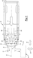
- an example vehicle 10 is illustrated with an impact body, i.e., a barrier 14, positioned in accordance with the Insurance Institute for Highway Safety ("IIHS") small overlap front impact testing.
- the barrier 14 is a rigid barrier such that the barrier 14 is fixed to the ground 18 to prevent movement of the barrier 14 in a longitudinal direction 22 or a lateral direction 26.
- the barrier 14 has an impacting face 30 and a generally rounded end 34.
- the vehicle 10 has a velocity V in the longitudinal direction 22 toward the barrier 14.
- the vehicle 10 has no velocity in the lateral direction 26 and the vehicle's 10 velocity V is perpendicular to the impact surface 30.
- the velocity V is 40mph, though other speeds can be used.
- the vehicle 10 has a central axis 38 running longitudinally through the vehicle 10 from a front 42 to a rear 46 of the vehicle 10 and bisecting the vehicle 10.
- the barrier 14 is positioned to impact the vehicle 10 in an outer quarter 50, i.e., outer 25%, of the vehicle's 10 total lateral width.
- the outer quarter 50 is delineated from an inner quarter 54 by an offset axis 58 that is offset from the central axis 38 by 25% of the total lateral width of the vehicle 10.
- the vehicle 10 and barrier 14 are positioned such that when the vehicle 10 impacts the barrier 14, the end 34 generally aligns with the offset axis 58.
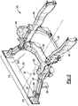
- the front structure 210 of the vehicle 10 includes a front left portion 214, a front right portion 218, delineated by the central axis 38, and a tension member 220.
- the front left portion 214 and the front right portion 218 are similarly constructed and are generally symmetrical about the central axis 38.
- the front left portion 214 includes a left side rail 222, a left suspension mount 226, a left rail tip 230, and a left half of the tension member 220.
- the front left portion 214 also includes a left half of a forward lateral rail 234 and a left half of a rearward lateral rail 238.
- the front right portion 218 includes a right side rail 242, a right suspension mount 246, a right rail tip 250, and a right half of the tension member 220.
- the front right portion 214 also includes a right half of the forward lateral rail 234 and a right half of the rearward lateral rail 238.
- the front right portion 218 and associated elements are substantially similar to the front left portion 214 and the similar associated elements, e.g., the left side rail 222, the left suspension mount 226, the left rail tip 230, the left half of the forward lateral rail 234, and the left half of the rearward lateral rail 238. Accordingly, only the front left portion 214 is described herein in detail.
- the left side rail 222 has a front terminal end 254, proximate to the front 42 of the vehicle 10, and the left side rail 222 extends in the longitudinal direction 22 from the front terminal end 254 toward the rear 46 of the vehicle 10.
- the left side rail 222 is laterally outboard of an engine 258 (schematically shown in Figure 3 ) of the vehicle 10.
- the forward lateral rail 234 extends in the lateral direction 26 and is fixedly attached to the left side rail 222 and the right side rail 242 proximate to the front 42 (e.g., proximate to the front terminal end 254) to connect the left side rail 222 to the right side rail 242.
- the forward lateral rail 234 has a generally "U” shape, with one end of the "U” shape attached to the left side rail 222, the other end of the "U” shape attached to the right side rail 242, and the trough of the "U” shape curving downward toward the ground accommodate the engine 258 (schematically shown in Figure 3 ) and/or a transmission (not shown) of the vehicle 10 mounted between the left side rail 222 and the right side rail 242.
- the rearward lateral rail 238 is rearward of the forward lateral rail 234 and extends in the lateral direction 26 and is fixedly attached to the left side rail 222 and the right side rail 242 to connect the left side rail 222 to the right side rail 242.
- the rearward lateral rail 238 also has a generally "U" shape, with one end of the "U” shape attached to the left side rail 222, the other end of the "U” shape attached to the right side rail 242, and the trough of the "U” shape curving downward toward the ground accommodate a portion of the engine 258 (schematically shown in Figure 3 ) and/or transmission (not shown) of the vehicle 10 mounted between the left side rail 222 and the right side rail 242.
- the left suspension mount 226 is fixedly attached to the left side rail 222.
- the left suspension mount 226 is located axially (i.e., in the longitudinal direction 22) between the forward lateral rail 234 and the rearward lateral rail 238.
- the left suspension mount 226 extends upward and laterally outboard of the left side rail 222 (i.e., the lateral direction 26 away from the central axis 38).
- the left suspension mount 226 is configured to be attached to a strut (not shown) of the vehicle 10.
- the left suspension mount 226 includes a spring cup 262 that is open generally downward such that the spring of the strut is received in the spring cup 262 to support the front structure 210 above the ground 18.
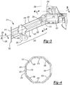
- the left rail tip 230 has a proximal end 310, a distal end 314, a crush body 318, and a tip plate 322.
- the proximal end 310 is fixedly attached to the front terminal end 254 of the left side rail 222.
- the crush body 318 extends from the front terminal end 254 forward and outboard therefrom to the distal end 314.
- the left rail tip 230 extends along a tip axis 326 that forms an angle 330 with the central axis 38 ( Figures 1 and 2 ), with the distal end 314 outboard of the proximal end 310.
- the left rail tip 230, and the tip axis 326 is generally parallel to the ground 18.
- the angle 330 is between 19°-25°, such as approximately 23° for example, though other angles outside of this range can be used depending on the configuration of the vehicle 10.
- the tip plate 322 is fixedly attached (e.g., welded) to the distal end 314.
- the tip plate 322 is a generally flat plate that is perpendicular to the central axis 38 and the ground 18.
- the distal end 314 terminates at the tip plate 322 along a plane (e.g., the rearward surface of the tip plate 322) that is perpendicular to the central axis 38.
- the tension member 220 is fixedly attached to the forward surfaces of the tip plates 322 and spans laterally between the two tip plates 322 generally across the front 42 of the vehicle 10.
- the tension member 220 is a structure that is tensionally rigid in the lateral direction 26 to inhibit relative lateral movement of the distal ends 314 away from each other.
- an energy absorbing member e.g., a crush can
- the tension member 220 is a thin metal plate that is bolted to the forward surfaces of the tip plates 322.
- the tension member 220 is a cable fixedly attached to the tip plates 322 and spanning laterally between the two tip plates 322 in tension.
- the front terminal end 254 of the left side rail 222 extends a short length along the tip axis 326.
- the front terminal end 254 has a hollow, tubular shape, having a polygonal cross-section.
- the front terminal end 254 has an octagonal cross-section centered about the tip axis 326.
- the left rail tip 230 has a hollow, tubular shape, having a polygonal cross-section similar to the front terminal end 254.
- the left rail tip 230 has an octagonal cross-section centered about the tip axis 326.
- the octagonal cross-section of the left rail tip 230 is slightly smaller than the octagonal cross-section of the front terminal end 254, such that the proximal end 310 fits coaxially within the front terminal end 254.
- the proximal end 310 is press-fit or slip-fit into the front terminal end 254 and then welded in place such that the proximal end 310 is fixedly attached to the front terminal end 254.
- the octagonal shape of the left rail tip 230 is such that the left rail tip 230 has flat, top and bottom walls 410, 414 that are parallel to the ground 18, a set of flat side walls 418, 422 that are perpendicular to the ground 18, and flat diagonal walls 426, 430, 434, 438 therebetween.
- brackets e.g., bracket 350 or bracket 354 shown in Figures 3 and 4
- body panels not specifically shown
- bumper components are easily mountable or weldable to the left rail tip 230.
- the interior and exterior surfaces of the left rail tip 230 are generally smooth and devoid of crush beads or indentions, which are typically used in other front structures (not shown) to provide controlled compression.
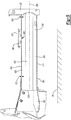
- the bracket 350 includes a mounting plate 510.
- the mounting plate 510 is fixedly coupled to the top wall 410 and has a top surface that is parallel to the top wall 410.
- the left rail tip 230 is formed such that the top and bottom walls 410, 414, the side walls 418, 422 and the diagonal walls 426, 430, 434, 438 have a thickness, i.e., gage, that tapers from the proximal end 310 to the distal end 314.
- the walls 410, 414, 418, 422, 426, 430, 434, 438 of the left rail tip 230 have a first thickness 522 at the proximal end 310 and a second thickness 526 at the distal end 314 that is thinner than the first thickness 522.
- the walls 410, 414, 418, 422, 426, 430, 434, 438 have an overall trend of narrowing from the proximal end 310 to the distal end 314.
- the thickness of the walls 410, 414, 418, 422, 426, 430, 434, 438 narrows smoothly and continuously from the proximal end 310 to the distal end 314 without discreet steps down in the thickness of the walls 410, 414, 418, 422, 426, 430, 434, 438.
- the walls 410, 414, 418, 422, 426, 430, 434, 438 have a constant thickness at any particular cross-section taken along a line perpendicular to the tip axis 326 (e.g., line 4-4).
- the walls 410, 414, 418, 422, 426, 430, 434, 438 have lengths where their thickness remains constant, while the overall trend still narrows from the proximal end 310 to the distal end 314.
- the thickness of the walls 410, 414, 418, 422, 426, 430, 434, 438 is thinner at a bracket (e.g., bracket 350, or 354) that is mounted to the walls 410, 414, 418, 422, 426, 430, 434, 438, than the thickness immediately forward of the bracket, but the overall trend of the walls 410, 414, 418, 422, 426, 430, 434, 438 narrowing from the proximal end 310 to the distal end 314 remains.
- This localized thinning 439 (i.e., area of reduced localized wall thickness) at the bracket compensates for the added structural rigidity provided by the bracket, thus ensuring desired crush properties of the left rail tip 230 are maintained even through the length of the left rail tip 230 that includes the bracket.
- This localized thinning 439 allows the crush characteristics to be tuned to the specific configuration of the rail tip 230.
- the barrier 14 and vehicle 10 are illustrated in a pre-impact condition wherein the barrier 14 is aligned to impact the outer quarter 50 of the left side of the vehicle 10, with the vehicle having a velocity V in the longitudinal direction 22 only, as described above with reference to Figure 1 .
- the barrier 14 is aligned to impact generally at the tip plate 322 and approximately at the tip axis 326 as the vehicle moves toward the barrier 14 in the longitudinal direction 22.
- the barrier 14 and vehicle 10 are illustrated in an impact condition after a predetermined amount of time after impact.
- the geometry of the left rail tip 230 including the tapered walls 410, 414, 418, 422, 426, 430, 434, 438 and the angle of the tip axis 326 causes the vehicle 10 to gain a lateral velocity component 710, in addition to the longitudinal velocity component 714, such that the barrier 14 progresses relative to the vehicle 10 laterally toward the central axis 38 generally along the tip axis 326.
- the left rail tip 230 crushes, i.e., compresses generally along the tip axis 326, absorbing some of the impact forces.
- a flat barrier 810 and the left rail tip 230 and right rail tip 250 are illustrated in a pre-impact condition.
- the flat barrier 810 has a flat impacting face 814 that is perpendicular to the central axis 38 of the vehicle 10.
- the flat barrier 810 and flat impacting face 814 extend laterally across the entire front 42 of the vehicle 10.
- the flat barrier 810 and vehicle 10 are illustrated in an impact condition after a predetermined amount of time after impact.
- the geometry of the left rail tip 230, including the tapered walls 410, 414, 418, 422, 426, 430, 434, 438 and the angle of the tip axis 326, along with the tension member 220 causes the left rail tip 230 to crush in a step-wise manner, absorbing some of the impact forces and minimizing material stack-up of the left rail tip 230.
- the right rail tip 250 is similarly constructed and also crushes in a step-wise manner, absorbing some of the impact forces and minimizing material stack-up of the right rail tip 250, similar to the left rail tip 230.
- the tension member 220 ties the left and right rail tips 230, 250 together in the lateral direction 26 to resist bending moments of the left and right rail tips 230, 250 during full, flat frontal impact events.
- the front structure 210 interacts with all front impact events without prematurely buckling and while providing progressive axial crush during small overlap and oblique impacts while minimizing material stack-up of fully crushed parts during full, flat frontal impacts. Furthermore, by minimizing material stack-up, the front structure 210 has the further added benefit of permitting the vehicle 10 to have an overall smaller front end.
Landscapes
- Engineering & Computer Science (AREA)
- Mechanical Engineering (AREA)
- Chemical & Material Sciences (AREA)
- Combustion & Propulsion (AREA)
- Transportation (AREA)
- Body Structure For Vehicles (AREA)
- Vehicle Interior And Exterior Ornaments, Soundproofing, And Insulation (AREA)
Description
- The present disclosure relates to a vehicle having a front structure with a splayed variable gage rail tip.
- This section provides background information related to the present disclosure which is not necessarily prior art.
- Vehicles conventionally have an internal body structure including a pair of rails extending longitudinally along the front of the vehicle and on opposite sides of the vehicle's power plant (e.g. engine). A bumper typically extends along the front of the vehicle, between the two rails. The rails typically support the power plant and any number of vehicle components or body panels. The bumper and rails are conventionally designed to absorb some of the forces that can occur during an impact event by deforming. The degree and location of such deformation can determine the trajectory of the vehicle during and after the impact event, and can influence the forces experienced by vehicle occupants. One type of impact event is known as a narrow offset impact (i.e., the IIHS small overlap crash test) where only the outer 25% of the vehicle's width is impacted by a rigid object (e.g., a barrier, wall, or vehicle) during the impact event. Another type of impact event is known as a flat frontal impact where the entire front of the vehicle impacts a flat, rigid object (e.g., a barrier, wall, or vehicle) during the impact event. Yet another type of impact event is known as a frontal oblique impact event where a movable, deformable object (e.g., a movable deformable barrier, or a vehicle) impacts the front corner of the vehicle at an angle relative to the vehicle.
- Examples of known vehicles structures are disclosed in documents
EP2621759 A1 ,US2014284948 A1 ,FR3038573 A1 EP2406109 A1 . DocumentUS 2014/284948 A1 discloses a vehicle front structure comprising: a left and respectively a right side rail extending longitudinally in a front portion of the vehicle on a left and respectively a right side of a central longitudinal axis of the vehicle; and a left and respectively a right rail tip, each having a plurality of flat walls defining a hollow polygonal body disposed about a left and respectively about a right tip axis, each of the left and the right rail tip having a proximal end and a distal end, wherein these proximal ends are fixedly coupled to a corresponding forward terminal end of the left and respectively right side rail. Moreover, a tension member is fixedly coupled to the distal ends of the left and right rail tips and spanning laterally therebetween. - The aforementioned aims are reached by a vehicle structure as claimed in the appended set of claims.
- The present invention will become more fully understood from the detailed description and the accompanying drawings, wherein:
-
Figure 1 is a top elevated view of an example of a vehicle and an impact body in accordance with the present disclosure; -
Figure 2 is a perspective view of a front structure of the vehicle ofFigure 1 ; -
Figure 3 is a top plan view of a portion of a front left portion of the front structure ofFigure 2 , illustrating a rail tip of the front left portion; -
Figure 4 is a sectional view of the rail tip ofFigure 3 , taken along line 4-4 ofFigure 3 ; -
Figure 5 is a sectional view of the rail tip ofFigure 3 , taken along line 5-5 ofFigure 3 ; -
Figure 6 is a top plan view of the front left portion ofFigure 3 , illustrating the impact body ofFigure 1 in a pre-impact position; -
Figure 7 is a top plan view similar toFigure 6 , illustrating movement of the vehicle relative to the impact body following impact with the impact body; -
Figure 8 is a top plan view of a portion of the front structure ofFigure 2 , including the front left portion ofFigure 3 and a front right portion, illustrating an impact body of a second construction in a pre-impact position; and -
Figure 9 is a top plan view similar toFigure 8 , illustrating movement of the vehicle relative to the impact body following impact with the impact body. - Corresponding reference numerals indicate corresponding parts throughout the several views of the drawings.
- The following description of the preferred embodiment(s) is merely exemplary in nature and is in no way intended to limit the invention, its application, or uses.
- The present disclosure relates to a vehicle having a front structure with a splayed, variable gage rail tip. This vehicle front structure permits dual-mode impact energy absorption at the front of the vehicle without the need for added parts such as reinforcements or blockers. The vehicle front structure allows for progressive, generally straight axial crush of the rail tip during small offset impacts, while also allowing progressive, shifting axial crush of the rail tip during flat barrier impacts. While illustrated and described with reference to the left side of the vehicle, it is understood that the vehicle is constructed to be substantially symmetric with regards to the right and left sides of the front structure of the present disclosure.
- With reference to
Figure 1 , anexample vehicle 10 is illustrated with an impact body, i.e., abarrier 14, positioned in accordance with the Insurance Institute for Highway Safety ("IIHS") small overlap front impact testing. Thebarrier 14 is a rigid barrier such that thebarrier 14 is fixed to theground 18 to prevent movement of thebarrier 14 in alongitudinal direction 22 or alateral direction 26. Thebarrier 14 has animpacting face 30 and a generallyrounded end 34. Thevehicle 10 has a velocity V in thelongitudinal direction 22 toward thebarrier 14. In the example provided, thevehicle 10 has no velocity in thelateral direction 26 and the vehicle's 10 velocity V is perpendicular to theimpact surface 30. In the example provided, the velocity V is 40mph, though other speeds can be used. Thevehicle 10 has acentral axis 38 running longitudinally through thevehicle 10 from afront 42 to a rear 46 of thevehicle 10 and bisecting thevehicle 10. Thebarrier 14 is positioned to impact thevehicle 10 in anouter quarter 50, i.e., outer 25%, of the vehicle's 10 total lateral width. In the example provided, theouter quarter 50 is delineated from aninner quarter 54 by anoffset axis 58 that is offset from thecentral axis 38 by 25% of the total lateral width of thevehicle 10. In other words, thevehicle 10 andbarrier 14 are positioned such that when thevehicle 10 impacts thebarrier 14, theend 34 generally aligns with theoffset axis 58. - With additional reference to
Figure 2 , afront structure 210 of thevehicle 10 is shown. Thefront structure 210 of thevehicle 10 includes a frontleft portion 214, a frontright portion 218, delineated by thecentral axis 38, and atension member 220. The frontleft portion 214 and the frontright portion 218 are similarly constructed and are generally symmetrical about thecentral axis 38. The frontleft portion 214 includes aleft side rail 222, aleft suspension mount 226, aleft rail tip 230, and a left half of thetension member 220. In the example provided, the frontleft portion 214 also includes a left half of a forwardlateral rail 234 and a left half of a rearwardlateral rail 238. Similarly, the frontright portion 218 includes aright side rail 242, aright suspension mount 246, aright rail tip 250, and a right half of thetension member 220. In the example provided, the frontright portion 214 also includes a right half of the forwardlateral rail 234 and a right half of the rearwardlateral rail 238. The frontright portion 218 and associated elements are substantially similar to the frontleft portion 214 and the similar associated elements, e.g., theleft side rail 222, theleft suspension mount 226, theleft rail tip 230, the left half of the forwardlateral rail 234, and the left half of the rearwardlateral rail 238. Accordingly, only the frontleft portion 214 is described herein in detail. - The
left side rail 222 has afront terminal end 254, proximate to thefront 42 of thevehicle 10, and theleft side rail 222 extends in thelongitudinal direction 22 from thefront terminal end 254 toward the rear 46 of thevehicle 10. Theleft side rail 222 is laterally outboard of an engine 258 (schematically shown inFigure 3 ) of thevehicle 10. The forwardlateral rail 234 extends in thelateral direction 26 and is fixedly attached to theleft side rail 222 and theright side rail 242 proximate to the front 42 (e.g., proximate to the front terminal end 254) to connect theleft side rail 222 to theright side rail 242. In the example provided, the forwardlateral rail 234 has a generally "U" shape, with one end of the "U" shape attached to theleft side rail 222, the other end of the "U" shape attached to theright side rail 242, and the trough of the "U" shape curving downward toward the ground accommodate the engine 258 (schematically shown inFigure 3 ) and/or a transmission (not shown) of thevehicle 10 mounted between theleft side rail 222 and theright side rail 242. The rearwardlateral rail 238 is rearward of the forwardlateral rail 234 and extends in thelateral direction 26 and is fixedly attached to theleft side rail 222 and theright side rail 242 to connect theleft side rail 222 to theright side rail 242. In the example provided, the rearwardlateral rail 238 also has a generally "U" shape, with one end of the "U" shape attached to theleft side rail 222, the other end of the "U" shape attached to theright side rail 242, and the trough of the "U" shape curving downward toward the ground accommodate a portion of the engine 258 (schematically shown inFigure 3 ) and/or transmission (not shown) of thevehicle 10 mounted between theleft side rail 222 and theright side rail 242. - The
left suspension mount 226 is fixedly attached to theleft side rail 222. In the example provided, theleft suspension mount 226 is located axially (i.e., in the longitudinal direction 22) between the forwardlateral rail 234 and the rearwardlateral rail 238. Theleft suspension mount 226 extends upward and laterally outboard of the left side rail 222 (i.e., thelateral direction 26 away from the central axis 38). Theleft suspension mount 226 is configured to be attached to a strut (not shown) of thevehicle 10. In the example provided, theleft suspension mount 226 includes aspring cup 262 that is open generally downward such that the spring of the strut is received in thespring cup 262 to support thefront structure 210 above theground 18. - With additional reference to
Figure 3 , theleft rail tip 230 has aproximal end 310, adistal end 314, acrush body 318, and atip plate 322. Theproximal end 310 is fixedly attached to the frontterminal end 254 of theleft side rail 222. Thecrush body 318 extends from the frontterminal end 254 forward and outboard therefrom to thedistal end 314. Thus, theleft rail tip 230 extends along atip axis 326 that forms anangle 330 with the central axis 38 (Figures 1 and2 ), with thedistal end 314 outboard of theproximal end 310. In the example provided, theleft rail tip 230, and thetip axis 326 is generally parallel to theground 18. In the example provided, theangle 330 is between 19°-25°, such as approximately 23° for example, though other angles outside of this range can be used depending on the configuration of thevehicle 10. - The
tip plate 322 is fixedly attached (e.g., welded) to thedistal end 314. In the example provided, thetip plate 322 is a generally flat plate that is perpendicular to thecentral axis 38 and theground 18. Thedistal end 314 terminates at thetip plate 322 along a plane (e.g., the rearward surface of the tip plate 322) that is perpendicular to thecentral axis 38. - Returning to
Figure 2 , and also shown inFigures 6 ,8 , and9 , thetension member 220 is fixedly attached to the forward surfaces of thetip plates 322 and spans laterally between the twotip plates 322 generally across thefront 42 of thevehicle 10. Thetension member 220 is a structure that is tensionally rigid in thelateral direction 26 to inhibit relative lateral movement of the distal ends 314 away from each other. While not specifically shown, an energy absorbing member (e.g., a crush can) may be fixedly mounted to the forward side of thetension member 220. In the example provided, thetension member 220 is a thin metal plate that is bolted to the forward surfaces of thetip plates 322. In an alternative construction, thetension member 220 is a cable fixedly attached to thetip plates 322 and spanning laterally between the twotip plates 322 in tension. - Returning to
Figure 3 and with additional reference toFigure 4 , the frontterminal end 254 of theleft side rail 222 extends a short length along thetip axis 326. The frontterminal end 254 has a hollow, tubular shape, having a polygonal cross-section. In the example provided, the frontterminal end 254 has an octagonal cross-section centered about thetip axis 326. Theleft rail tip 230 has a hollow, tubular shape, having a polygonal cross-section similar to the frontterminal end 254. In the example provided, theleft rail tip 230 has an octagonal cross-section centered about thetip axis 326. In the example provided, the octagonal cross-section of theleft rail tip 230 is slightly smaller than the octagonal cross-section of the frontterminal end 254, such that theproximal end 310 fits coaxially within the frontterminal end 254. In the example provided, theproximal end 310 is press-fit or slip-fit into the frontterminal end 254 and then welded in place such that theproximal end 310 is fixedly attached to the frontterminal end 254. - With specific reference to
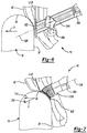
Figure 4 , the octagonal shape of theleft rail tip 230 is such that theleft rail tip 230 has flat, top andbottom walls ground 18, a set offlat side walls ground 18, and flatdiagonal walls bracket 350 orbracket 354 shown inFigures 3 and 4 ), body panels (not specifically shown), or bumper components (not specifically shown) are easily mountable or weldable to theleft rail tip 230. In the example provided, the interior and exterior surfaces of theleft rail tip 230 are generally smooth and devoid of crush beads or indentions, which are typically used in other front structures (not shown) to provide controlled compression. - With additional reference to
Figure 5 , a cross-sectional view of theleft rail tip 230 and the frontterminal end 254 is illustrated, taken along the tip axis 326 (i.e., line 5-5 shown inFigure 3 ). In the example provided, thebracket 350 includes a mountingplate 510. The mountingplate 510 is fixedly coupled to thetop wall 410 and has a top surface that is parallel to thetop wall 410. Theleft rail tip 230 is formed such that the top andbottom walls side walls diagonal walls proximal end 310 to thedistal end 314. In other words, thewalls left rail tip 230 have afirst thickness 522 at theproximal end 310 and asecond thickness 526 at thedistal end 314 that is thinner than thefirst thickness 522. Thewalls proximal end 310 to thedistal end 314. In the example provided, the thickness of thewalls proximal end 310 to thedistal end 314 without discreet steps down in the thickness of thewalls Figure 4 , thewalls - In an alternative construction, the
walls proximal end 310 to thedistal end 314. In an alternative construction, the thickness of thewalls bracket 350, or 354) that is mounted to thewalls walls proximal end 310 to thedistal end 314 remains. This localized thinning 439 (i.e., area of reduced localized wall thickness) at the bracket compensates for the added structural rigidity provided by the bracket, thus ensuring desired crush properties of theleft rail tip 230 are maintained even through the length of theleft rail tip 230 that includes the bracket. This localized thinning 439 allows the crush characteristics to be tuned to the specific configuration of therail tip 230. - With reference to
Figure 1 and additional reference toFigure 6 , thebarrier 14 andvehicle 10 are illustrated in a pre-impact condition wherein thebarrier 14 is aligned to impact theouter quarter 50 of the left side of thevehicle 10, with the vehicle having a velocity V in thelongitudinal direction 22 only, as described above with reference toFigure 1 . Thebarrier 14 is aligned to impact generally at thetip plate 322 and approximately at thetip axis 326 as the vehicle moves toward thebarrier 14 in thelongitudinal direction 22. - With additional reference to
Figure 7 , thebarrier 14 andvehicle 10 are illustrated in an impact condition after a predetermined amount of time after impact. The geometry of theleft rail tip 230, including the taperedwalls tip axis 326 causes thevehicle 10 to gain alateral velocity component 710, in addition to thelongitudinal velocity component 714, such that thebarrier 14 progresses relative to thevehicle 10 laterally toward thecentral axis 38 generally along thetip axis 326. Theleft rail tip 230 crushes, i.e., compresses generally along thetip axis 326, absorbing some of the impact forces. - With additional reference to
Figure 8 , aflat barrier 810 and theleft rail tip 230 andright rail tip 250 are illustrated in a pre-impact condition. Theflat barrier 810 has aflat impacting face 814 that is perpendicular to thecentral axis 38 of thevehicle 10. Theflat barrier 810 andflat impacting face 814 extend laterally across theentire front 42 of thevehicle 10. - With additional reference to
Figure 9 , theflat barrier 810 andvehicle 10 are illustrated in an impact condition after a predetermined amount of time after impact. The geometry of theleft rail tip 230, including the taperedwalls tip axis 326, along with thetension member 220 causes theleft rail tip 230 to crush in a step-wise manner, absorbing some of the impact forces and minimizing material stack-up of theleft rail tip 230. Theright rail tip 250 is similarly constructed and also crushes in a step-wise manner, absorbing some of the impact forces and minimizing material stack-up of theright rail tip 250, similar to theleft rail tip 230. Thetension member 220 ties the left andright rail tips lateral direction 26 to resist bending moments of the left andright rail tips - Accordingly, the
front structure 210 interacts with all front impact events without prematurely buckling and while providing progressive axial crush during small overlap and oblique impacts while minimizing material stack-up of fully crushed parts during full, flat frontal impacts. Furthermore, by minimizing material stack-up, thefront structure 210 has the further added benefit of permitting thevehicle 10 to have an overall smaller front end. - The description of the invention is merely exemplary in nature and, thus, all variations envisaged by one skilled in the art are encompassed by the scope of the present invention as defined in the appended claims.
Claims (13)
- A vehicle (10) front structure (210) comprising:a left side rail (222) extending longitudinally in a front portion of the vehicle (10) on a left side of a central longitudinal axis (38) of the vehicle (10);a left rail tip (230) having a plurality of flat walls (410, 414, 418, 422, 426, 430, 434, 438) defining a hollow polygonal body disposed about a left tip axis (326), the left rail tip (230) having a proximal end (310) and a distal end (314), the proximal end (310) of the left rail tip (230) being fixedly coupled to a forward terminal end (254) of the left side rail (222), the proximal end (310) of the left rail tip (230) being disposed inboard of an outer left quarter (50) of a total width of the vehicle (10), the left rail tip (230) extending outboard and forward from the proximal end (310) to the distal end (314) of the left rail tip (230), the distal end (314) of the left rail tip (230) being disposed within the outer left quarter (50) of the total width of the vehicle (10), each of the flat walls (410, 414, 418, 422, 426, 430, 434, 438) of the left rail tip (230) having a forward wall thickness (526) at the distal end (314) of the left rail tip (230) and a rearward wall thickness at the proximal end (310) of the left rail tip (230), the forward wall thickness (526) of the flat walls (410, 414, 418, 422, 426, 430, 434, 438) of the left rail tip (230) being less than the rearward wall thickness (522) of the flat walls (410, 414, 418, 422, 426, 430, 434, 438) of the left rail tip (230);a right side rail extending longitudinally in the front portion of the vehicle (10) on a right side of the central longitudinal axis (38) of the vehicle (10);a right rail tip (250) having a plurality of flat walls defining a hollow polygonal body disposed about a right tip axis, the right rail tip (250) having a proximal end and a distal end, the proximal end of the right rail tip (250) being fixedly coupled to a forward terminal end of the right side rail, the proximal end of the right rail tip (250) being disposed inboard of an outer right quarter of the total width of the vehicle (10), the right rail tip (250) extending outboard and forward from the proximal end to the distal end of the right rail tip (250), the distal end of the right rail tip (250) being disposed within the outer right quarter of the total width of the vehicle (10), each of the flat walls of the right rail tip (250) having a forward wall thickness at the distal end of the right rail tip (250) and a rearward wall thickness at the proximal end of the right rail tip (250), the forward wall thickness of the flat walls of the right rail tip (250) being less than the rearward wall thickness of the flat walls of the right rail tip (250); anda tension member (220) fixedly coupled to the distal ends (314) of the left and right rail tips (230, 250) and spanning laterally therebetween.
- The vehicle (10) front structure (210) of Claim 1, wherein each of the flat walls (410, 414, 418, 422, 426, 430, 434, 438) of the left rail tip (230) has an intermediate wall thickness between the forward and rearward wall thicknesses, the intermediate wall thickness of the flat walls (410, 414, 418, 422, 426, 430, 434, 438) of the left rail tip (230) has an overall trend of narrowing from the proximal end (310) to the distal end (314) of the left rail tip (230), wherein each of the flat walls (410, 414, 418, 422, 426, 430, 434, 438) of the right rail tip (250) has an intermediate wall thickness between the forward and rearward wall thickness, the intermediate wall thickness of the flat walls (410, 414, 418, 422, 426, 430, 434, 438) of the right rail tip (250) has an overall trend of narrowing from the proximal end to the distal end of the right rail tip (250).
- The vehicle (10) front structure (210) of Claim 1, wherein the proximal ends (310) of the left and right rail tips (230, 250) are received in a corresponding one of the forward terminal ends (254) of the left and right side rails.
- The vehicle (10) front structure (210) of Claim 3, wherein the proximal end (310) of the left rail tip (230) and the forward terminal end (254) of the left side rail (222) have coaxial octagonal cross-sections, wherein the proximal end of the right rail tip (250) and the forward terminal end of the right side rail have coaxial octagonal cross-sections.
- The vehicle (10) front structure (210) of Claim 1, wherein the hollow polygonal body of the left rail tip (230) has an octagonal cross-section disposed coaxial about the left tip axis (326), wherein the hollow polygonal body of the right rail tip (250) has an octagonal cross-section disposed coaxial about the right tip axis.
- The vehicle (10) front structure (210) of Claim 1, wherein the left rail tip (230) and the right rail tip (250) are devoid of crush beads.
- The vehicle (10) front structure (210) of Claim 1, further comprising a left tip plate (322) and a right tip plate, the left tip plate (322) fixedly attached to the distal end (314) of the left rail tip (230), the left tip plate (322) being perpendicular to the central longitudinal axis (38) of the vehicle (10), the right tip plate fixedly attached to the distal end of the right rail tip (250), the right tip plate being perpendicular to the central longitudinal axis (38) of the vehicle (10).
- The vehicle (10) front structure (210) of Claim 7, wherein the left tip plate (322) has a planar rear facing surface that abuts the distal end (314) of the left rail tip (230) at a plane that is perpendicular to the central longitudinal axis (38) of the vehicle (10), wherein the right tip plate has a planar rear facing surface that abuts the distal end of the right rail tip (250) at the front plane.
- The vehicle (10) front structure (210) of Claim 1, further comprising a bracket (350) fixedly mounted to at least one of the flat walls (410, 414, 418, 422, 426, 430, 434, 438) of the left rail tip (230).
- The vehicle (10) front structure (210) of Claim 9, wherein the at least one of the flat walls (410, 414, 418, 422, 426, 430, 434, 438) of the left rail tip (230) has a localized wall thickness where the bracket (350) is mounted, the localized wall thickness being thinner than an adjacent wall thickness of the at least one of the flat walls (410, 414, 418, 422, 426, 430, 434, 438), the adjacent wall thickness being immediately forward of the localized wall thickness.
- The vehicle (10) front structure (210) of Claim 1, wherein the flat walls (410, 414, 418, 422, 426, 430, 434, 438) of the left rail tip (230) have a constant thickness taken about a cross-section perpendicular to the left tip axis (326), wherein the flat walls (410, 414, 418, 422, 426, 430, 434, 438) of the right rail tip (250) have a constant thickness taken about a cross-section perpendicular to the right tip axis.
- The vehicle (10) front structure (210) of Claim 1, wherein the left tip axis (326) forms an angle with the central longitudinal axis (38) that is between 19°-25°, wherein the right tip axis forms an angle with the central longitudinal axis that is between 19°-25°.
- The vehicle (10) front structure (210) of Claim 1, wherein the left and right tip axes are parallel to a level ground surface when the vehicle (10) is positioned for operation on the level ground surface.
Applications Claiming Priority (2)
| Application Number | Priority Date | Filing Date | Title |
|---|---|---|---|
| US15/461,730 US10077077B1 (en) | 2017-03-17 | 2017-03-17 | Vehicle front structure with splayed variable gage rail tip |
| PCT/US2018/022428 WO2018170123A1 (en) | 2017-03-17 | 2018-03-14 | Vehicle front structure with splayed variable gage rail tip |
Publications (2)
| Publication Number | Publication Date |
|---|---|
| EP3595959A1 EP3595959A1 (en) | 2020-01-22 |
| EP3595959B1 true EP3595959B1 (en) | 2021-08-25 |
Family
ID=61906843
Family Applications (1)
| Application Number | Title | Priority Date | Filing Date |
|---|---|---|---|
| EP18716040.3A Active EP3595959B1 (en) | 2017-03-17 | 2018-03-14 | Vehicle front structure with splayed variable gage rail tip |
Country Status (4)
| Country | Link |
|---|---|
| US (1) | US10077077B1 (en) |
| EP (1) | EP3595959B1 (en) |
| MX (1) | MX2019010842A (en) |
| WO (1) | WO2018170123A1 (en) |
Families Citing this family (3)
| Publication number | Priority date | Publication date | Assignee | Title |
|---|---|---|---|---|
| DE102019200582B3 (en) * | 2019-01-17 | 2020-03-19 | Audi Ag | Support structure for a vehicle body |
| US11034316B2 (en) * | 2019-08-23 | 2021-06-15 | Volvo Car Corporation | Mounting arrangement for coupling a bumper beam to a crash box and side rail of a vehicle |
| CN113335382B (en) * | 2021-06-17 | 2022-06-07 | 东风柳州汽车有限公司 | Separation arrangement structure of pipeline at cross beam of commercial vehicle |
Family Cites Families (39)
| Publication number | Priority date | Publication date | Assignee | Title |
|---|---|---|---|---|
| US3499661A (en) | 1968-03-22 | 1970-03-10 | Luther Kemp Rowe Jr | Lateral planing frame and bumper assembly |
| DE2043525A1 (en) | 1970-09-02 | 1972-03-09 | Daimler Benz Ag, 7000 Stuttgart | Bumper assembly |
| JP2595724B2 (en) | 1989-08-30 | 1997-04-02 | 日産自動車株式会社 | Manufacturing method of strength member |
| US5533780A (en) | 1994-12-08 | 1996-07-09 | Chrysler Corporation | Front crossmember assembly for a motor vehicle |
| JP3381444B2 (en) | 1995-03-03 | 2003-02-24 | 日産自動車株式会社 | Strength member structure of vehicle body |
| EP0921051B1 (en) | 1997-11-30 | 2002-05-15 | Isuzu Motors Limited | Front portion structure of vehicle frame |
| ATE247017T1 (en) * | 1998-11-26 | 2003-08-15 | Lotus Car | DEFORMABLE SUPPORTS FOR VEHICLES |
| US6655728B2 (en) | 2000-04-25 | 2003-12-02 | Nissan Motor Co., Ltd. | Body structure of vehicle |
| JP3693899B2 (en) | 2000-07-31 | 2005-09-14 | ダイハツ工業株式会社 | Impact force absorbing structure at the front of the vehicle body in automobiles |
| JP3578087B2 (en) | 2001-01-19 | 2004-10-20 | 日産自動車株式会社 | Automotive power unit layout |
| JP3765238B2 (en) | 2001-02-27 | 2006-04-12 | 日産自動車株式会社 | Body front structure |
| JP3632666B2 (en) | 2002-02-01 | 2005-03-23 | 日産自動車株式会社 | Body front structure |
| US6588830B1 (en) | 2002-07-01 | 2003-07-08 | Daimlerchrysler Corporation | Energy absorbing frame rail tip |
| JP4122887B2 (en) | 2002-08-05 | 2008-07-23 | 日産自動車株式会社 | Body front structure |
| JP3786093B2 (en) | 2003-02-07 | 2006-06-14 | 日産自動車株式会社 | Body front structure |
| CA2534653C (en) | 2003-08-06 | 2012-12-04 | Dofasco Tubular Products Inc. | Vehicle frame having energy management system and method for making same |
| US6938948B1 (en) | 2004-02-27 | 2005-09-06 | Daimlerchrysler Corporation | Energy absorbing front frame structure for a vehicle |
| WO2005110815A1 (en) | 2004-05-17 | 2005-11-24 | Magna Steyr Fahrzeugtechnik Ag & Co Kg | Deflector device for protecting motor vehicles in the event of a partially overlapping frontal collision |
| JP2006015859A (en) | 2004-07-01 | 2006-01-19 | Nissan Motor Co Ltd | Front body structure of the vehicle |
| JP4506577B2 (en) | 2004-09-21 | 2010-07-21 | トヨタ自動車株式会社 | Vehicle front structure |
| US7699346B2 (en) | 2005-03-23 | 2010-04-20 | Chrysler Group Llc | Force redistributing system for a vehicle in the event of a rear impact |
| JP4801462B2 (en) | 2006-02-16 | 2011-10-26 | 本田技研工業株式会社 | Lower body structure |
| JP2008222185A (en) | 2007-03-16 | 2008-09-25 | Mazda Motor Corp | Body front structure |
| US8539737B2 (en) * | 2008-09-19 | 2013-09-24 | Ford Global Technologies, Llc | Twelve-cornered strengthening member |
| US9533710B2 (en) | 2008-09-19 | 2017-01-03 | Ford Global Technologies, Llc | Twelve-cornered strengthening member |
| JP4653210B2 (en) * | 2008-11-12 | 2011-03-16 | 本田技研工業株式会社 | Body front structure |
| IT1395087B1 (en) * | 2009-03-12 | 2012-09-05 | Red Stamp Sas | SHOCK ABSORPTION ELEMENT |
| US8276955B2 (en) | 2010-03-26 | 2012-10-02 | Ford Global Technologies, Llc | Zero stack-up telescopically collapsible energy absorbing rail and bracket assembly |
| IT1401982B1 (en) * | 2010-09-28 | 2013-08-28 | Tres Srl | POLYMERIC IMPACT ABSORPTION ELEMENT FOR A VEHICLE AND BUMPER STRUCTURE. |
| JP5357953B2 (en) | 2011-04-01 | 2013-12-04 | 本田技研工業株式会社 | Body front structure |
| FR2978410B1 (en) | 2011-07-29 | 2013-08-09 | Peugeot Citroen Automobiles Sa | LONGERON FOR AUTOMOTIVE VEHICLE OF OCTAGONAL CROSS SECTION AND VEHICLE EQUIPPED WITH SUCH LONGERONS. |
| KR101316876B1 (en) | 2012-07-03 | 2013-10-08 | 기아자동차주식회사 | Bumper assembly for vehicle |
| KR101448747B1 (en) | 2012-10-02 | 2014-10-08 | 현대자동차 주식회사 | Front vehicle body structure |
| CN105121230B (en) * | 2013-03-20 | 2017-05-24 | 夏伊洛工业公司 | Energy absorbing components for vehicles |
| US9802654B2 (en) * | 2013-07-22 | 2017-10-31 | GM Global Technology Operations LLC | Method of assembling a vehicle uniframe |
| JP5983569B2 (en) | 2013-09-11 | 2016-08-31 | トヨタ自動車株式会社 | Vehicle front structure |
| CN103600773B (en) | 2013-10-30 | 2016-03-16 | 奇瑞汽车股份有限公司 | A kind of continuous variable cross section automobile front longitudinal beam and preparation method thereof |
| US9308940B1 (en) | 2014-12-17 | 2016-04-12 | Fca Us Llc | Vehicle front structure for absorbing small offset impact forces |
| FR3038573A1 (en) * | 2015-07-06 | 2017-01-13 | Peugeot Citroen Automobiles Sa | REAR STRUCTURE OF VEHICLE FOR URBAN SHOCK |
-
2017
- 2017-03-17 US US15/461,730 patent/US10077077B1/en active Active
-
2018
- 2018-03-14 MX MX2019010842A patent/MX2019010842A/en unknown
- 2018-03-14 WO PCT/US2018/022428 patent/WO2018170123A1/en not_active Ceased
- 2018-03-14 EP EP18716040.3A patent/EP3595959B1/en active Active
Also Published As
| Publication number | Publication date |
|---|---|
| WO2018170123A1 (en) | 2018-09-20 |
| MX2019010842A (en) | 2019-12-16 |
| US10077077B1 (en) | 2018-09-18 |
| US20180265132A1 (en) | 2018-09-20 |
| EP3595959A1 (en) | 2020-01-22 |
Similar Documents
| Publication | Publication Date | Title |
|---|---|---|
| US10661834B2 (en) | Vehicle front structure with splayed rail tips | |
| US7695052B2 (en) | Front rail having controlled thickness for energy absorption | |
| EP3233608B1 (en) | Vehicle front structure for absorbing small offset impact forces | |
| US7677617B2 (en) | Efficient joint for vehicle energy-absorbing device | |
| US7887122B2 (en) | One-piece shotgun with impact energy absorber | |
| US9216767B2 (en) | Front axle mounting with crash grooves | |
| EP1653114A1 (en) | Impact-absorbing member | |
| KR102375069B1 (en) | absence of hollow | |
| KR102365534B1 (en) | hollow member | |
| US10252686B2 (en) | Lightweight extruded aluminum bumper | |
| EP3190031B1 (en) | Automobile member | |
| EP3670272B1 (en) | Bumper beam and vehicle | |
| US9868468B1 (en) | Vehicle front structure for lateral deflection during narrow offset impact | |
| US10077077B1 (en) | Vehicle front structure with splayed variable gage rail tip | |
| EP4003792B1 (en) | Vehicle bumper extension with crush can bracing | |
| US20240149816A1 (en) | Vehicle reinforcement beam | |
| WO2014153482A1 (en) | Energy absorbing assembly for vehicle | |
| US20190144039A1 (en) | Small overlap impact countermeasure for vehicle | |
| US9266486B2 (en) | Impact absorbing structure | |
| EP1468889B1 (en) | Coupler for a railway vehicle, with a rubber damper and energy absorbing members | |
| US9744996B2 (en) | Vehicle front structure | |
| CN114174089B (en) | Reinforcement structure of automobile exterior panels | |
| CN208855391U (en) | Door anti-collision joist, door assembly and vehicle | |
| JP2014145368A (en) | Crash box made of steel |
Legal Events
| Date | Code | Title | Description |
|---|---|---|---|
| STAA | Information on the status of an ep patent application or granted ep patent |
Free format text: STATUS: UNKNOWN |
|
| STAA | Information on the status of an ep patent application or granted ep patent |
Free format text: STATUS: THE INTERNATIONAL PUBLICATION HAS BEEN MADE |
|
| PUAI | Public reference made under article 153(3) epc to a published international application that has entered the european phase |
Free format text: ORIGINAL CODE: 0009012 |
|
| STAA | Information on the status of an ep patent application or granted ep patent |
Free format text: STATUS: REQUEST FOR EXAMINATION WAS MADE |
|
| 17P | Request for examination filed |
Effective date: 20191009 |
|
| AK | Designated contracting states |
Kind code of ref document: A1 Designated state(s): AL AT BE BG CH CY CZ DE DK EE ES FI FR GB GR HR HU IE IS IT LI LT LU LV MC MK MT NL NO PL PT RO RS SE SI SK SM TR |
|
| AX | Request for extension of the european patent |
Extension state: BA ME |
|
| RIN1 | Information on inventor provided before grant (corrected) |
Inventor name: PURVIS, ADRIAN J. Inventor name: LEGRAY, JAMES V. Inventor name: MROZINSKI, BRYAN G. Inventor name: ZILINCIK, SCOTT E. |
|
| DAV | Request for validation of the european patent (deleted) | ||
| DAX | Request for extension of the european patent (deleted) | ||
| REG | Reference to a national code |
Ref country code: DE Ref legal event code: R079 Ref document number: 602018022373 Country of ref document: DE Free format text: PREVIOUS MAIN CLASS: B62D0021150000 Ipc: B62D0021060000 |
|
| GRAP | Despatch of communication of intention to grant a patent |
Free format text: ORIGINAL CODE: EPIDOSNIGR1 |
|
| STAA | Information on the status of an ep patent application or granted ep patent |
Free format text: STATUS: GRANT OF PATENT IS INTENDED |
|
| RIC1 | Information provided on ipc code assigned before grant |
Ipc: B62D 21/09 20060101ALI20210301BHEP Ipc: B62D 21/15 20060101ALI20210301BHEP Ipc: B62D 21/06 20060101AFI20210301BHEP Ipc: B60R 19/34 20060101ALI20210301BHEP |
|
| INTG | Intention to grant announced |
Effective date: 20210316 |
|
| GRAS | Grant fee paid |
Free format text: ORIGINAL CODE: EPIDOSNIGR3 |
|
| GRAA | (expected) grant |
Free format text: ORIGINAL CODE: 0009210 |
|
| STAA | Information on the status of an ep patent application or granted ep patent |
Free format text: STATUS: THE PATENT HAS BEEN GRANTED |
|
| AK | Designated contracting states |
Kind code of ref document: B1 Designated state(s): AL AT BE BG CH CY CZ DE DK EE ES FI FR GB GR HR HU IE IS IT LI LT LU LV MC MK MT NL NO PL PT RO RS SE SI SK SM TR |
|
| REG | Reference to a national code |
Ref country code: CH Ref legal event code: EP |
|
| REG | Reference to a national code |
Ref country code: IE Ref legal event code: FG4D Ref country code: AT Ref legal event code: REF Ref document number: 1423531 Country of ref document: AT Kind code of ref document: T Effective date: 20210915 |
|
| REG | Reference to a national code |
Ref country code: DE Ref legal event code: R096 Ref document number: 602018022373 Country of ref document: DE |
|
| REG | Reference to a national code |
Ref country code: LT Ref legal event code: MG9D |
|
| REG | Reference to a national code |
Ref country code: NL Ref legal event code: MP Effective date: 20210825 |
|
| REG | Reference to a national code |
Ref country code: AT Ref legal event code: MK05 Ref document number: 1423531 Country of ref document: AT Kind code of ref document: T Effective date: 20210825 |
|
| PG25 | Lapsed in a contracting state [announced via postgrant information from national office to epo] |
Ref country code: ES Free format text: LAPSE BECAUSE OF FAILURE TO SUBMIT A TRANSLATION OF THE DESCRIPTION OR TO PAY THE FEE WITHIN THE PRESCRIBED TIME-LIMIT Effective date: 20210825 Ref country code: FI Free format text: LAPSE BECAUSE OF FAILURE TO SUBMIT A TRANSLATION OF THE DESCRIPTION OR TO PAY THE FEE WITHIN THE PRESCRIBED TIME-LIMIT Effective date: 20210825 Ref country code: HR Free format text: LAPSE BECAUSE OF FAILURE TO SUBMIT A TRANSLATION OF THE DESCRIPTION OR TO PAY THE FEE WITHIN THE PRESCRIBED TIME-LIMIT Effective date: 20210825 Ref country code: RS Free format text: LAPSE BECAUSE OF FAILURE TO SUBMIT A TRANSLATION OF THE DESCRIPTION OR TO PAY THE FEE WITHIN THE PRESCRIBED TIME-LIMIT Effective date: 20210825 Ref country code: SE Free format text: LAPSE BECAUSE OF FAILURE TO SUBMIT A TRANSLATION OF THE DESCRIPTION OR TO PAY THE FEE WITHIN THE PRESCRIBED TIME-LIMIT Effective date: 20210825 Ref country code: NO Free format text: LAPSE BECAUSE OF FAILURE TO SUBMIT A TRANSLATION OF THE DESCRIPTION OR TO PAY THE FEE WITHIN THE PRESCRIBED TIME-LIMIT Effective date: 20211125 Ref country code: PT Free format text: LAPSE BECAUSE OF FAILURE TO SUBMIT A TRANSLATION OF THE DESCRIPTION OR TO PAY THE FEE WITHIN THE PRESCRIBED TIME-LIMIT Effective date: 20211227 Ref country code: AT Free format text: LAPSE BECAUSE OF FAILURE TO SUBMIT A TRANSLATION OF THE DESCRIPTION OR TO PAY THE FEE WITHIN THE PRESCRIBED TIME-LIMIT Effective date: 20210825 Ref country code: BG Free format text: LAPSE BECAUSE OF FAILURE TO SUBMIT A TRANSLATION OF THE DESCRIPTION OR TO PAY THE FEE WITHIN THE PRESCRIBED TIME-LIMIT Effective date: 20211125 Ref country code: LT Free format text: LAPSE BECAUSE OF FAILURE TO SUBMIT A TRANSLATION OF THE DESCRIPTION OR TO PAY THE FEE WITHIN THE PRESCRIBED TIME-LIMIT Effective date: 20210825 |
|
| PG25 | Lapsed in a contracting state [announced via postgrant information from national office to epo] |
Ref country code: PL Free format text: LAPSE BECAUSE OF FAILURE TO SUBMIT A TRANSLATION OF THE DESCRIPTION OR TO PAY THE FEE WITHIN THE PRESCRIBED TIME-LIMIT Effective date: 20210825 Ref country code: LV Free format text: LAPSE BECAUSE OF FAILURE TO SUBMIT A TRANSLATION OF THE DESCRIPTION OR TO PAY THE FEE WITHIN THE PRESCRIBED TIME-LIMIT Effective date: 20210825 Ref country code: GR Free format text: LAPSE BECAUSE OF FAILURE TO SUBMIT A TRANSLATION OF THE DESCRIPTION OR TO PAY THE FEE WITHIN THE PRESCRIBED TIME-LIMIT Effective date: 20211126 |
|
| PG25 | Lapsed in a contracting state [announced via postgrant information from national office to epo] |
Ref country code: NL Free format text: LAPSE BECAUSE OF FAILURE TO SUBMIT A TRANSLATION OF THE DESCRIPTION OR TO PAY THE FEE WITHIN THE PRESCRIBED TIME-LIMIT Effective date: 20210825 |
|
| PG25 | Lapsed in a contracting state [announced via postgrant information from national office to epo] |
Ref country code: DK Free format text: LAPSE BECAUSE OF FAILURE TO SUBMIT A TRANSLATION OF THE DESCRIPTION OR TO PAY THE FEE WITHIN THE PRESCRIBED TIME-LIMIT Effective date: 20210825 |
|
| REG | Reference to a national code |
Ref country code: DE Ref legal event code: R097 Ref document number: 602018022373 Country of ref document: DE |
|
| PG25 | Lapsed in a contracting state [announced via postgrant information from national office to epo] |
Ref country code: SM Free format text: LAPSE BECAUSE OF FAILURE TO SUBMIT A TRANSLATION OF THE DESCRIPTION OR TO PAY THE FEE WITHIN THE PRESCRIBED TIME-LIMIT Effective date: 20210825 Ref country code: SK Free format text: LAPSE BECAUSE OF FAILURE TO SUBMIT A TRANSLATION OF THE DESCRIPTION OR TO PAY THE FEE WITHIN THE PRESCRIBED TIME-LIMIT Effective date: 20210825 Ref country code: RO Free format text: LAPSE BECAUSE OF FAILURE TO SUBMIT A TRANSLATION OF THE DESCRIPTION OR TO PAY THE FEE WITHIN THE PRESCRIBED TIME-LIMIT Effective date: 20210825 Ref country code: EE Free format text: LAPSE BECAUSE OF FAILURE TO SUBMIT A TRANSLATION OF THE DESCRIPTION OR TO PAY THE FEE WITHIN THE PRESCRIBED TIME-LIMIT Effective date: 20210825 Ref country code: CZ Free format text: LAPSE BECAUSE OF FAILURE TO SUBMIT A TRANSLATION OF THE DESCRIPTION OR TO PAY THE FEE WITHIN THE PRESCRIBED TIME-LIMIT Effective date: 20210825 Ref country code: AL Free format text: LAPSE BECAUSE OF FAILURE TO SUBMIT A TRANSLATION OF THE DESCRIPTION OR TO PAY THE FEE WITHIN THE PRESCRIBED TIME-LIMIT Effective date: 20210825 |
|
| PLBE | No opposition filed within time limit |
Free format text: ORIGINAL CODE: 0009261 |
|
| STAA | Information on the status of an ep patent application or granted ep patent |
Free format text: STATUS: NO OPPOSITION FILED WITHIN TIME LIMIT |
|
| 26N | No opposition filed |
Effective date: 20220527 |
|
| PG25 | Lapsed in a contracting state [announced via postgrant information from national office to epo] |
Ref country code: SI Free format text: LAPSE BECAUSE OF FAILURE TO SUBMIT A TRANSLATION OF THE DESCRIPTION OR TO PAY THE FEE WITHIN THE PRESCRIBED TIME-LIMIT Effective date: 20210825 |
|
| PG25 | Lapsed in a contracting state [announced via postgrant information from national office to epo] |
Ref country code: MC Free format text: LAPSE BECAUSE OF FAILURE TO SUBMIT A TRANSLATION OF THE DESCRIPTION OR TO PAY THE FEE WITHIN THE PRESCRIBED TIME-LIMIT Effective date: 20210825 |
|
| REG | Reference to a national code |
Ref country code: CH Ref legal event code: PL |
|
| REG | Reference to a national code |
Ref country code: BE Ref legal event code: MM Effective date: 20220331 |
|
| PG25 | Lapsed in a contracting state [announced via postgrant information from national office to epo] |
Ref country code: LU Free format text: LAPSE BECAUSE OF NON-PAYMENT OF DUE FEES Effective date: 20220314 Ref country code: LI Free format text: LAPSE BECAUSE OF NON-PAYMENT OF DUE FEES Effective date: 20220331 Ref country code: IE Free format text: LAPSE BECAUSE OF NON-PAYMENT OF DUE FEES Effective date: 20220314 Ref country code: CH Free format text: LAPSE BECAUSE OF NON-PAYMENT OF DUE FEES Effective date: 20220331 |
|
| PG25 | Lapsed in a contracting state [announced via postgrant information from national office to epo] |
Ref country code: BE Free format text: LAPSE BECAUSE OF NON-PAYMENT OF DUE FEES Effective date: 20220331 |
|
| PG25 | Lapsed in a contracting state [announced via postgrant information from national office to epo] |
Ref country code: MK Free format text: LAPSE BECAUSE OF FAILURE TO SUBMIT A TRANSLATION OF THE DESCRIPTION OR TO PAY THE FEE WITHIN THE PRESCRIBED TIME-LIMIT Effective date: 20210825 Ref country code: CY Free format text: LAPSE BECAUSE OF FAILURE TO SUBMIT A TRANSLATION OF THE DESCRIPTION OR TO PAY THE FEE WITHIN THE PRESCRIBED TIME-LIMIT Effective date: 20210825 |
|
| PG25 | Lapsed in a contracting state [announced via postgrant information from national office to epo] |
Ref country code: HU Free format text: LAPSE BECAUSE OF FAILURE TO SUBMIT A TRANSLATION OF THE DESCRIPTION OR TO PAY THE FEE WITHIN THE PRESCRIBED TIME-LIMIT; INVALID AB INITIO Effective date: 20180314 |
|
| PG25 | Lapsed in a contracting state [announced via postgrant information from national office to epo] |
Ref country code: TR Free format text: LAPSE BECAUSE OF FAILURE TO SUBMIT A TRANSLATION OF THE DESCRIPTION OR TO PAY THE FEE WITHIN THE PRESCRIBED TIME-LIMIT Effective date: 20210825 |
|
| PG25 | Lapsed in a contracting state [announced via postgrant information from national office to epo] |
Ref country code: MT Free format text: LAPSE BECAUSE OF FAILURE TO SUBMIT A TRANSLATION OF THE DESCRIPTION OR TO PAY THE FEE WITHIN THE PRESCRIBED TIME-LIMIT Effective date: 20210825 |
|
| PGFP | Annual fee paid to national office [announced via postgrant information from national office to epo] |
Ref country code: GB Payment date: 20260327 Year of fee payment: 9 |
|
| PGFP | Annual fee paid to national office [announced via postgrant information from national office to epo] |
Ref country code: DE Payment date: 20260327 Year of fee payment: 9 |
|
| PGFP | Annual fee paid to national office [announced via postgrant information from national office to epo] |
Ref country code: IT Payment date: 20260319 Year of fee payment: 9 |
|
| PGFP | Annual fee paid to national office [announced via postgrant information from national office to epo] |
Ref country code: FR Payment date: 20260325 Year of fee payment: 9 |