EP3595871B1 - Unité d'imprimante pour appareil et procédé d'impression 3d - Google Patents
Unité d'imprimante pour appareil et procédé d'impression 3d Download PDFInfo
- Publication number
- EP3595871B1 EP3595871B1 EP18707389.5A EP18707389A EP3595871B1 EP 3595871 B1 EP3595871 B1 EP 3595871B1 EP 18707389 A EP18707389 A EP 18707389A EP 3595871 B1 EP3595871 B1 EP 3595871B1
- Authority
- EP
- European Patent Office
- Prior art keywords
- printing
- printer
- nozzle
- printer unit
- printer head
- Prior art date
- Legal status (The legal status is an assumption and is not a legal conclusion. Google has not performed a legal analysis and makes no representation as to the accuracy of the status listed.)
- Active
Links
- 238000007639 printing Methods 0.000 title claims description 76
- 238000000034 method Methods 0.000 title claims description 18
- 239000000463 material Substances 0.000 claims description 120
- 238000010146 3D printing Methods 0.000 claims description 36
- 238000000151 deposition Methods 0.000 claims description 25
- 230000008021 deposition Effects 0.000 claims description 19
- 238000012876 topography Methods 0.000 claims description 5
- 238000013016 damping Methods 0.000 claims description 4
- 238000010438 heat treatment Methods 0.000 claims description 4
- 230000001788 irregular Effects 0.000 description 2
- 238000004519 manufacturing process Methods 0.000 description 2
- 239000000654 additive Substances 0.000 description 1
- 230000000996 additive effect Effects 0.000 description 1
- 230000000903 blocking effect Effects 0.000 description 1
- 230000006835 compression Effects 0.000 description 1
- 238000007906 compression Methods 0.000 description 1
- 238000005094 computer simulation Methods 0.000 description 1
- 230000001419 dependent effect Effects 0.000 description 1
- 238000012986 modification Methods 0.000 description 1
- 230000004048 modification Effects 0.000 description 1
- 238000000465 moulding Methods 0.000 description 1
- 229920001169 thermoplastic Polymers 0.000 description 1
- 239000004416 thermosoftening plastic Substances 0.000 description 1
Images
Classifications
-
- B—PERFORMING OPERATIONS; TRANSPORTING
- B29—WORKING OF PLASTICS; WORKING OF SUBSTANCES IN A PLASTIC STATE IN GENERAL
- B29C—SHAPING OR JOINING OF PLASTICS; SHAPING OF MATERIAL IN A PLASTIC STATE, NOT OTHERWISE PROVIDED FOR; AFTER-TREATMENT OF THE SHAPED PRODUCTS, e.g. REPAIRING
- B29C64/00—Additive manufacturing, i.e. manufacturing of three-dimensional [3D] objects by additive deposition, additive agglomeration or additive layering, e.g. by 3D printing, stereolithography or selective laser sintering
- B29C64/20—Apparatus for additive manufacturing; Details thereof or accessories therefor
- B29C64/205—Means for applying layers
- B29C64/209—Heads; Nozzles
-
- B—PERFORMING OPERATIONS; TRANSPORTING
- B29—WORKING OF PLASTICS; WORKING OF SUBSTANCES IN A PLASTIC STATE IN GENERAL
- B29C—SHAPING OR JOINING OF PLASTICS; SHAPING OF MATERIAL IN A PLASTIC STATE, NOT OTHERWISE PROVIDED FOR; AFTER-TREATMENT OF THE SHAPED PRODUCTS, e.g. REPAIRING
- B29C64/00—Additive manufacturing, i.e. manufacturing of three-dimensional [3D] objects by additive deposition, additive agglomeration or additive layering, e.g. by 3D printing, stereolithography or selective laser sintering
- B29C64/10—Processes of additive manufacturing
- B29C64/106—Processes of additive manufacturing using only liquids or viscous materials, e.g. depositing a continuous bead of viscous material
- B29C64/118—Processes of additive manufacturing using only liquids or viscous materials, e.g. depositing a continuous bead of viscous material using filamentary material being melted, e.g. fused deposition modelling [FDM]
-
- B—PERFORMING OPERATIONS; TRANSPORTING
- B29—WORKING OF PLASTICS; WORKING OF SUBSTANCES IN A PLASTIC STATE IN GENERAL
- B29C—SHAPING OR JOINING OF PLASTICS; SHAPING OF MATERIAL IN A PLASTIC STATE, NOT OTHERWISE PROVIDED FOR; AFTER-TREATMENT OF THE SHAPED PRODUCTS, e.g. REPAIRING
- B29C64/00—Additive manufacturing, i.e. manufacturing of three-dimensional [3D] objects by additive deposition, additive agglomeration or additive layering, e.g. by 3D printing, stereolithography or selective laser sintering
- B29C64/20—Apparatus for additive manufacturing; Details thereof or accessories therefor
- B29C64/227—Driving means
- B29C64/232—Driving means for motion along the axis orthogonal to the plane of a layer
-
- B—PERFORMING OPERATIONS; TRANSPORTING
- B29—WORKING OF PLASTICS; WORKING OF SUBSTANCES IN A PLASTIC STATE IN GENERAL
- B29C—SHAPING OR JOINING OF PLASTICS; SHAPING OF MATERIAL IN A PLASTIC STATE, NOT OTHERWISE PROVIDED FOR; AFTER-TREATMENT OF THE SHAPED PRODUCTS, e.g. REPAIRING
- B29C64/00—Additive manufacturing, i.e. manufacturing of three-dimensional [3D] objects by additive deposition, additive agglomeration or additive layering, e.g. by 3D printing, stereolithography or selective laser sintering
- B29C64/20—Apparatus for additive manufacturing; Details thereof or accessories therefor
- B29C64/245—Platforms or substrates
-
- B—PERFORMING OPERATIONS; TRANSPORTING
- B33—ADDITIVE MANUFACTURING TECHNOLOGY
- B33Y—ADDITIVE MANUFACTURING, i.e. MANUFACTURING OF THREE-DIMENSIONAL [3-D] OBJECTS BY ADDITIVE DEPOSITION, ADDITIVE AGGLOMERATION OR ADDITIVE LAYERING, e.g. BY 3-D PRINTING, STEREOLITHOGRAPHY OR SELECTIVE LASER SINTERING
- B33Y10/00—Processes of additive manufacturing
-
- B—PERFORMING OPERATIONS; TRANSPORTING
- B33—ADDITIVE MANUFACTURING TECHNOLOGY
- B33Y—ADDITIVE MANUFACTURING, i.e. MANUFACTURING OF THREE-DIMENSIONAL [3-D] OBJECTS BY ADDITIVE DEPOSITION, ADDITIVE AGGLOMERATION OR ADDITIVE LAYERING, e.g. BY 3-D PRINTING, STEREOLITHOGRAPHY OR SELECTIVE LASER SINTERING
- B33Y30/00—Apparatus for additive manufacturing; Details thereof or accessories therefor
Definitions
- the present invention generally relates to the field of 3D printing. More specifically, the present invention relates to a printer unit for a 3D printing apparatus, and a printing method.
- Additive manufacturing sometimes also referred to as 3D printing, refers to processes used to synthesize a three-dimensional object. 3D printing is rapidly gaining popularity because of its ability to perform rapid prototyping without the need for assembly or molding techniques to form the desired article.
- an article or object may be built in three dimensions in a number of printing steps that often are controlled by a computer model.
- a sliced 3D model of the object may be provided in which each slice is recreated by the 3D printing apparatus in a discrete printing step.
- FFF printers often use a thermoplastic filament which in its molten state is ejected from a nozzle of the printer. The material is then placed layer by layer, to create a three-dimensional object. FFF printers are relatively fast and can be used for printing objects of various kinds, even those having relatively complex structures.
- the deposited layer of printing material may be provided as a relatively smooth, homogeneous surface.
- US-2016/271871 discloses a 3D printer having a printer robot with a carrier, a control module that controls movement of the carrier by controlling the printer robot, and a printer head detachably connected to the carrier, wherein the printer head has a nozzle for delivering a printing material to print a 3D object.
- the printer head comprises a calibration module for performing a calibration of the printer head.
- the calibration module has a sliding shaft, a ring PCB board, a bearing holder, and a spring.
- the ring PCB board is fixed to the upper end of the bearing holder.
- the lower end of the bearing holder is connected to the spring.
- the sliding shaft is provided in a bearing of the bearing holder.
- the ring PCB board has a calibration circuit that is connected to the control module of the printer robot when the ring PCB board touches the sliding shaft.
- the sliding shaft is mechanically connected to the nozzle of the printer head.
- the bearing holder can move further towards the platform, and when that happens the spring is compressed, the ring PCB board becomes disconnected from the sliding shaft, and the electrical connection to the control module of the printer robot is interrupted.
- the aforementioned calibration is done to ensure that the printing of the 3D object starts from a flat imaginary plane.
- a printer unit for a 3D-printing apparatus for deposition of a printing material comprises a printer head comprising a nozzle.
- the nozzle is arranged to deposit, in a vertical direction and on an underlying material, at least one filament of a printing material supplied to the nozzle.
- the printer head is resiliently suspended in the printer unit in a vertical direction by at least one resilient means, allowing a vertical movement of the printer head during deposition of the printing material.
- the suspended printer head in its equilibrium is positionable above the underlying material at a vertical distance before deposition.
- the at least one resilient means is configured to become biased by a vertical force on the nozzle from the printing material on the underlying material, such that the printer head moves from its equilibrium into a position at a desired vertical distance from the underlying material.
- the printer unit further comprises a first actuator configured to at least partially impede the vertical movement of the printer head.
- a method of 3D printing comprises the step of providing a printer unit according to the first aspect of the present invention.
- the method further comprises the step of positioning the suspended printer head in its equilibrium position above an underlying material at a vertical distance before depositing printing material on the underlying material.
- the method further comprises the step of depositing, by the nozzle, at least one filament of a printing material supplied to the nozzle on the underlying material, whereby the at least one resilient means is configured to become biased by a vertical force on the nozzle from the printing material on the underlying material, such that the printer head moves from its equilibrium into a position at a desired vertical distance from the underlying material.
- the present invention is based on the idea of providing a printer unit for a 3D-printing apparatus which is configured to deposit a printing material to generate a homogeneous surface that is smooth over a relatively large area.
- the nozzle is resiliently mounted in a vertical direction, and this freedom of movement allows the nozzle to follow the undulations of the underlying material (e.g. a build-plate or previously deposited printing material).
- the present invention may keep the distance between the nozzle and the underlying material relatively constant even in case of an uneven topography of the underlying material, which ensures that the printing material adheres to the underlying material and obtains a predicted layer thickness and width.
- build-plates having relatively large areas may often comprise irregularities such as bumps, waves, etc., and this may especially be the case when the build-plates are heated.
- the present invention is therefore highly advantageous in that a printing material deposited on a build-plate as underlying material may be provided as a smooth and homogeneous layer.
- the resulting surface finish may be poor due to an inconsistent nozzle-to-build-plate distance.
- the present invention overcomes this problem, as the nozzle is resiliently mounted in a vertical direction, allowing the nozzle to follow the undulations of the underlying material, leading to an improved surface finish.
- the printer unit of the present invention comprises a printer head comprising a nozzle.
- the nozzle is arranged to deposit, in a vertical direction and on an underlying material, at least one filament of a printing material supplied to the nozzle.
- underlying material it is here meant a build-plate (platform), one or more previously deposited layers of printing material, etc.
- the printer head is resiliently suspended in the printer unit in a vertical direction by at least one resilient means.
- resiliently suspended it is here meant that the printer unit is mounted, arranged, or the like, in a resilient manner.
- resilient means it is here meant one or more springs, coils, rubber bands, air-pistons, magnetic devices, air pressure/hydraulic cylinder, etc.
- the suspended printer head in its equilibrium is positionable above the underlying material at a vertical distance before deposition.
- equilibrium it is here meant the force balance of the suspended printer head in a vertical direction.
- the at least one resilient means is configured to become biased by a vertical force on the nozzle from the printing material on the underlying material, such that the printer head moves from its equilibrium into a position at a desired vertical distance from the underlying material.
- the printing material exerts a downward force on the underlying material.
- the force of the printing material biases the spring upwards in a vertical direction, thereby pushing the nozzle upwards in a vertical direction.
- the at least one resilient means comprises at least one spring.
- the present embodiment is advantageous in that the spring(s) provides a convenient way of maintaining the downward exerted force constant and thereby maintaining a relatively constant distance between the nozzle and the underlying material.
- the printer head further comprises a first control unit configured to control the force constant of the resilient means.
- the first control unit may adapt the force constant of the resilient means during printing.
- the present embodiment is advantageous in that the first control unit may efficiently adapt the resilience of the resilient means during printing, thereby contributing to an even smoother and/or more homogeneous surface of the printing material.
- the force constant of the at least one resilient means is determined as a function of at least one of a viscosity of the printing material, a topography of the underlying material and a flow rate of the deposition of the printing material.
- the force constant of the resilient means may be determined based on one or more of the viscosity of the printing material, a topography of the underlying material, and the flow rate of the deposition of the printing material. Consequently, the force constant may compensate for a different printing material used, a variation of the underlying material and/or a deposition flow rate.
- the present embodiment is advantageous in that a smoothness of the deposited layer may be achieved to an even higher degree.
- the printer unit further comprises a first actuator configured to at least partially impede the vertical movement of the printer head.
- the first actuator may be configured to limit the vertical movement of the printer head when needed.
- the first actuator may be configured to block the vertical movement of the printer head.
- the first actuator is operable by at least one of electromagnetism, hydraulics and air pressure. Furthermore, the first actuator may, according to an embodiment of the present invention, comprise at least one damping means.
- a 3D-printing apparatus comprising a printer unit according to any one of the preceding embodiments, and a second actuator configured to displace the printer unit in a vertical direction.
- the printer unit comprising a resiliently suspended printer head
- the printer unit may additionally be equipped with an (electrical) actuator like a stepper or servo motor.
- the actuator may accurately move the printer unit vertically (i.e. up and down).
- the possibility to actively control the height position of the printer head is enabled, and the distance between the underlying material and the nozzle may be actively controlled.
- the 3D-printing apparatus may further comprise a plurality of printer heads.
- a plurality of printer heads it is here meant either a 3D-printing apparatus having at least two printer heads mounted on the apparatus, or that a printer head mounted on the apparatus may be exchanged for another printer head.
- the possibility of the second actuator to displace the printer unit in a vertical direction is especially useful for a 3D-printing apparatus comprising a plurality of printer heads, as each printer head may have its own individual levelling calibration relating the nozzle and/or printer head, and/or correction relating the build-plate-to-nozzle height.
- a 3D-printing arrangement comprises a printer unit according to any one of the preceding embodiments, and a build-plate arranged in a horizontal plane, wherein the nozzle is arranged to deposit at least one filament of a printing material upon the build-plate.
- irregularities such as bumps, waves, projections, etc., may be frequently occurring on build-plate surfaces.
- the present invention is therefore highly advantageous in that a printing material deposited on a build-plate as underlying material may be provided as a smooth and homogeneous layer.
- At least one heating unit configured to heat the build-plate.
- the present embodiment is advantageous in that the heating unit(s) provide a better adhesion of the printing material deposited upon the build-plate.
- the heating unit(s) provide a better adhesion of the printing material deposited upon the build-plate.
- the possibility of the present invention to allow the nozzle to provide (a) smooth layer(s), in spite of undulations of the underlying material, is of even higher importance.
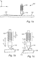
- Fig. 1a shows a schematic view of a printer unit 100 for a 3D-printing apparatus. It will be appreciated that the printer unit 100 may comprise additional elements, features, etc. However, these are omitted in Fig. 1a for an increased understanding.
- the printer unit 100 comprises a printer head comprising a nozzle 110 arranged to deposit, in a vertical direction and on an underlying material, at least one filament 115 of a printing material supplied to the nozzle 110.
- the underlying material is exemplified as a slightly undulated build-plate 130, but may alternatively constitute at least one layer of (previously deposited) printing material.
- build-plates 130 may be supported and levelled at several points, usually proportional to the size of the build-plate 130, for minimizing the warp of the build-plate 130. After levelling, there is often a certain non-flatness remaining of the build-plate 130. This causes variations in the distance between the nozzle 110 and the build-plate 130, and may furthermore generate variations in surface appearance.
- the printing material is extruded from the bottom portion of the tapered nozzle 110.
- the first layer of printing material is normally printed with a relatively small layer thickness of 0.1-0.2 mm. It will be appreciated that the distance between the nozzle 110 and the underlying material 130 needs to be well-controlled to produce a relatively smooth surface.
- the nozzle 110 may be heated by a heater whereby the temperature is kept at a level at which the printing material can flow readily.
- the deposition of the filament(s) 115 of the printing material is provided in a direction of movement of the nozzle 110 from left to right, i.e. along the x-axis. It will be appreciated that individual filaments 115 may be deposited by the printer unit 100 on top of each other, or alternatively, be arranged adjacently such that the filaments 115 constitute one or more layers.
- the printer head is resiliently suspended in the printer unit 100 in a vertical direction (z) by one or more resilient means 120.
- the resilient means is exemplified as a spring 120, but may alternatively take on other forms.
- the resilient means 120 allows a vertical movement of the printer head during deposition of the printing material.
- Fig. 1b shows the resiliently suspended printer head in its equilibrium.
- the arrangement of the spring 120 in relation to the nozzle 110 is merely provided as an example, for illustrative purposes and/or for an increased understanding.
- the stretched (biased) spring 120 Before deposition of printing material, the stretched (biased) spring 120 has a length l 1 , whereas the length of the unbiased spring 120 is l 0 ⁇ l 1 .
- the tip of the nozzle 110 is hereby positionable at a vertical distance ⁇ z 1 above the underlying material 130. It will be appreciated that the spring 120 can be mounted in compression or extension.
- Fig. 1c shows the printer head during deposition of the printing material from the nozzle 110 of the printer unit 100.
- the stretched (biased) spring 120 has a length l 2 , wherein l 2 ⁇ l 1 .
- the force F 3 results in a movement of the printer head from its equilibrium of Fig. 1b into a position at a desired, vertical distance ⁇ z 2 in the z-direction from the underlying material 130.
- the printer head may conveniently follow the underlying material 130 (e.g. a build-plate), even if the underlying material 130 is undulated, irregular and/or non-flat, and create a relatively smooth surface of printing material.
- the printer unit 100 may comprise a first control unit (not shown) configured to control the force constant (k) of the resilient means 120.
- the force constant may be determined as a function of the viscosity of the printing material. Hence, if the printing material is e.g. relatively thick (high viscosity) or, alternatively, relatively thin (low viscosity), the force constant may be determined (set) accordingly. Furthermore, the force constant may be determined as a function of the topography of the underlying material 130. For example, if the underlying material 130 (e.g. a build-plate) is relatively flat, or alternatively, relatively undulated, irregular, dented, damaged, etc., the force constant may be determined (set) accordingly.
- the underlying material 130 e.g. a build-plate
- the printer unit 100 may comprise a first actuator (exemplified in Figs. 2b-d ) coupled to the resilient means 120.
- the first actuator may be configured to at least partially impede the vertical movement of the printer head.
- the first actuator may be configured to (completely) block the vertical movement of the printer head.
- the first actuator may be operable by e.g. electromagnetism and/or air pressure.
- the first actuator may further comprise one or more damping means (e.g. one or more dampers).
- the damper may be configured to generate a force F 4 (not shown) proportional to the negative velocity of the printer head in the vertical direction.
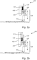
- Fig. 2a is a schematic view of a printer unit 100 according to an exemplifying embodiment of the present invention.
- printing material 170 is fed to the nozzle 110 by a feeder 180.
- the resilient means 120 in the form of a spring, is coupled to a carriage 185 and a housing 190 of the feeder 180. Between the carriage 185 and the housing 190, there is provided a fixture 200 (e.g. a guide rail) which can move in a vertical direction.
- the printer head 105 exemplified as the nozzle 110, the feeder 180 and the housing 190, is resiliently suspended in the printer unit 100 in the vertical direction by the spring 120, allowing a vertical movement of the printer head 105 during deposition of the printing material 170.
- Fig. 2b is a schematic view of a printer unit 100, similar to that exemplified in Fig. 2a .
- a first actuator 210 is coupled to one end of the spring 120 and the carriage 185, i.e. the first actuator 210 is coupled in series with the spring 120.
- the first actuator 210 is hereby configured to at least partially impede the vertical movement of the printer head 105.
- the first actuator 210 may constitute a means for active impedance control.
- a first actuator 220 is coupled between the housing 190 and the carriage 185, and is coupled in parallel with the spring 120.
- the first actuator 220 may constitute an active damper and/or brake for damping and/or breaking the vertical movement of the printer head 105.
- Fig. 2d is yet another schematic view of a printer unit 100, similar to those exemplified in Figs. 2a-c .
- the carriage 185 is formed as a staple, wherein the spring 120 is coupled between a first flange of the staple-shaped carriage 185 and the housing 190, and wherein a first actuator 230 is coupled between the housing 190 and a second flange of the staple-shaped carriage 185.
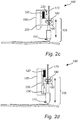
- Fig. 3 is a schematic view of a 3D-printing apparatus 300 according to an embodiment of the present invention.
- the 3D-printing apparatus 300 comprises a printer unit 100 according to Figs. 1a-c and/or Fig. 2 .
- the 3D-printing apparatus 300 comprises a second actuator 310 configured to displace the printer unit 100 in a vertical direction (z-direction). More specifically, the second actuator 310 comprises a motor configured to act on a pushrod 320 which in turn may move the printer unit 100 downwards or upwards.
- the second, (electrical) actuator 310 may be a stepper motor or servo motor.
- the 3D-printing apparatus 300 as shown may accurately control the movement of the printer unit 100 vertically (i.e. up and down). As a consequence, the possibility to actively control the height position of the printer head is enabled, and the distance between the underlying material and the nozzle 110 may be actively controlled.
- the 3D-printing apparatus 300 in Fig. 3 may further comprise a plurality of printer heads, i.e. at least two printer heads mounted on the apparatus or a set of exchangeable printer heads.
- Fig. 4 is a schematic view of a 3D-printing arrangement 400 according to an embodiment of the present invention.
- the 3D-printing arrangement 400 comprises a printer unit according to any one of the preceding embodiments, and a build-plate 130 arranged in a horizontal plane, wherein the nozzle 110 is arranged to deposit one or more filaments of a printing material upon the build-plate 130.
- the 3D-printing arrangement 400 comprises a (schematically indicated) heating unit 410 configured to heat the build-plate 130 for a better adhesion of the printing material deposited upon the build-plate 130.
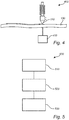
- Fig. 5 is a schematic view of a method 500 according to an exemplifying embodiment of the present invention.
- the method comprises the step of providing 510 a printer unit according to the first aspect of the present invention.
- the method further comprises the step of positioning 520 the suspended printer head in its equilibrium position above an underlying material before depositing printing material on the underlying material.
- the method further comprises the step of depositing 530, by the nozzle, at least one filament of a printing material supplied to the nozzle on the underlying material, whereby the at least one resilient means is configured to become biased by a vertical force on the nozzle from the printing material on the underlying material, such that the printer head moves from its equilibrium into a position at a desired vertical distance from the underlying material.
- any elements/components of the printer unit 100 such as the nozzle 110, the spring 120, etc., may have different dimensions, shapes and/or sizes than those depicted and/or described.
- the nozzle 110 and/or the spring 120 may be larger or smaller than what is exemplified in the figures.
Claims (12)
- Unité d'imprimante (100) pour un appareil d'impression 3D pour le dépôt d'un matériau d'impression, comprenant
une tête d'imprimante (105) comprenant une buse (110) agencée pour déposer, dans un sens vertical (z) et sur un matériau sous-jacent, au moins un filament d'un matériau d'impression fourni à la buse,
dans laquelle la tête d'imprimante (105) est suspendue de façon élastique dans l'unité d'imprimante (100) dans le sens vertical par au moins un moyen élastique (120), permettant un mouvement vertical de la tête d'imprimante (105) pendant le dépôt du matériau d'impression,
dans laquelle la tête d'imprimante suspendue (105) dans son équilibre est repositionnable au-dessus du matériau sous-jacent à une distance verticale (Δz1) avant le dépôt,
dans laquelle pendant le dépôt, le au moins un moyen élastique (120) est configuré pour être sollicité par une force verticale (F3) sur la buse (110) depuis le matériau vertical sur le matériau sous-jacent, de telle sorte que la tête d'imprimante (105) se déplace de son équilibre dans une position à une distance verticale souhaitée (Δz2) depuis le matériau sous-jacent, et
dans laquelle l'unité d'imprimante (100) comprend en outre un premier actionneur (210, 220, 230) configuré pour au moins partiellement ralentir le mouvement vertical de la tête d'imprimante. - Unité d'imprimante (100) selon la revendication 1, dans laquelle le au moins un moyen élastique (120) comprend au moins un ressort.
- Unité d'imprimante (100) selon la revendication 1 ou 2, comprenant en outre une première unité de commande configurée pour commander la constante de force (k) du moyen élastique (120).
- Unité d'imprimante (100) selon l'une quelconque des revendications 1 à 3, dans laquelle la constante de force de l'au moins un moyen élastique (120) est déterminée comme une fonction d'au moins un parmi
une viscosité du matériau d'impression
une topographie du matériau sous-jacent, et
un débit du dépôt du matériau d'impression. - Unité d'imprimante (100) selon l'une quelconque des revendications 1 à 4, dans laquelle le premier actionneur (210, 220, 230) est configuré pour bloquer le mouvement vertical de la tête d'imprimante (105).
- Unité d'imprimante (100) selon l'une quelconque des revendications 1 à 5, dans laquelle le premier actionneur (210, 220, 230) fonctionne par l'intermédiaire d'au moins un parmi l'électromagnétisme, l'hydraulique et la pression d'air.
- Unité d'imprimante (100) selon l'une quelconque des revendications 1 à 6, dans laquelle le premier actionneur (210, 220, 230) comprend au moins un moyen d'amortissement.
- Appareil d'impression 3D (300) comprenant
une unité d'imprimante (100) selon l'une quelconque des revendications 1 à 7, et
un second actionneur (310) configuré pour déplacer l'unité d'imprimante (100) dans un sens vertical - Appareil d'impression 3D (300) selon la revendication 8, comprenant en outre une pluralité de têtes d'impression (100).
- Agencement d'impression 3D (400) comprenant
une unité d'imprimante (100) selon l'une quelconque des revendications 1 à 7, et
une plaque de construction (130) agencée dans un plan horizontal,
dans lequel la buse (110) est agencée pour déposer au moins un filament d'un matériau d'impression sur la plaque de construction (130). - Agencement d'impression 3D (400) selon la revendication 10, comprenant en outre au moins une unité de chauffage (410) configurée pour chauffer la plaque de construction (130)
- Procédé (500) comprenant les étapes de :fourniture (510) d'une unité d'imprimante (100) selon l'une quelconque des revendications 1 à 7 ;positionnement (520) de la tête d'imprimante suspendue (105) dans sa position d'équilibre au-dessus d'un matériau sous-jacent à une distance verticale (Δz1) avant le dépôt du matériau d'impression sur le matériau sous-jacent,dépôt (530), par la buse (110), d'au moins un filament d'un matériau d'impression fourni à la buse (110) sur le matériau sous-jacent, par lequel le au moins un moyen élastique (120) est configuré pour être sollicité par une force verticale (F3) sur la buse (110) depuis le matériau d'impression sur le matériau sous-jacent, de telle sorte que la tête d'imprimante (100) se déplace depuis son équilibre vers une position à une distance verticale souhaitée (Δz2) depuis le matériau sous-jacent.
Applications Claiming Priority (2)
| Application Number | Priority Date | Filing Date | Title |
|---|---|---|---|
| EP17160716 | 2017-03-14 | ||
| PCT/EP2018/055324 WO2018166827A1 (fr) | 2017-03-14 | 2018-03-05 | Unité d'imprimante pour appareil d'impression 3d et procédé |
Publications (2)
| Publication Number | Publication Date |
|---|---|
| EP3595871A1 EP3595871A1 (fr) | 2020-01-22 |
| EP3595871B1 true EP3595871B1 (fr) | 2020-11-04 |
Family
ID=58347103
Family Applications (1)
| Application Number | Title | Priority Date | Filing Date |
|---|---|---|---|
| EP18707389.5A Active EP3595871B1 (fr) | 2017-03-14 | 2018-03-05 | Unité d'imprimante pour appareil et procédé d'impression 3d |
Country Status (5)
| Country | Link |
|---|---|
| US (1) | US11273597B2 (fr) |
| EP (1) | EP3595871B1 (fr) |
| JP (1) | JP7096265B2 (fr) |
| CN (1) | CN110430990B (fr) |
| WO (1) | WO2018166827A1 (fr) |
Families Citing this family (5)
| Publication number | Priority date | Publication date | Assignee | Title |
|---|---|---|---|---|
| WO2017218645A1 (fr) * | 2016-06-14 | 2017-12-21 | Nike Innovate C.V. | Ensembles de buses à ressort |
| US10780635B1 (en) * | 2019-10-08 | 2020-09-22 | Thermwood Corporation | Apparatus and method for thermal compensation during additive manufacturing |
| IT201900020272A1 (it) * | 2019-11-04 | 2021-05-04 | Roboze Spa | Sistema di calibrazione per l’azzeramento automatico della effettiva coordinata verticale z corrispondente alla punta di un estrusore di stampanti 3d. |
| JP7447444B2 (ja) | 2019-11-27 | 2024-03-12 | セイコーエプソン株式会社 | 三次元造形装置 |
| KR102302559B1 (ko) * | 2019-12-27 | 2021-09-16 | 비즈텍코리아 주식회사 | 정량토출이 가능한 3차원 프린터 및 이것의 제어 방법 |
Family Cites Families (14)
| Publication number | Priority date | Publication date | Assignee | Title |
|---|---|---|---|---|
| WO2000078519A1 (fr) * | 1999-06-23 | 2000-12-28 | Stratasys, Inc. | Appareil de faconnage a temperature elevee |
| US6722872B1 (en) * | 1999-06-23 | 2004-04-20 | Stratasys, Inc. | High temperature modeling apparatus |
| KR100873195B1 (ko) | 2007-06-13 | 2008-12-10 | 인하대학교 산학협력단 | 디스펜서 헤드 |
| US9126365B1 (en) | 2013-03-22 | 2015-09-08 | Markforged, Inc. | Methods for composite filament fabrication in three dimensional printing |
| CN203651190U (zh) | 2013-11-28 | 2014-06-18 | 深圳市迈创彩印机械设备有限公司 | 喷墨机喷头定位控制装置及喷墨机 |
| CA2884018C (fr) | 2014-02-26 | 2022-06-21 | Freespace Composites Inc. | Systeme de fabrication employant un logiciel de conception d'optimisation de topologie, mecanismes novateurs d'impression en trois dimensions et materiaux composites structurels |
| US10286606B2 (en) | 2014-09-15 | 2019-05-14 | Massachusetts Institute Of Technology | Methods and apparatus for additive manufacturing along user-specified toolpaths |
| US10766802B2 (en) | 2014-11-29 | 2020-09-08 | National Tsing Hua University | Flexible 3D freeform techniques |
| CN104742368B (zh) | 2015-03-06 | 2017-09-08 | 英华达(上海)科技有限公司 | 一种打印喷头、立体成型设备和打印方法 |
| US20160271871A1 (en) * | 2015-03-17 | 2016-09-22 | Alt Design Co., Ltd. | 3d printing device |
| CN204955426U (zh) | 2015-08-06 | 2016-01-13 | 成都墨之坊科技有限公司 | 智能挤出机及智能3d打印机 |
| CN109070447A (zh) * | 2016-02-11 | 2018-12-21 | 马丁·库斯特 | 用于三维打印机的可移动的打印装置 |
| CN105711093A (zh) | 2016-02-19 | 2016-06-29 | 昆山市奇迹三维科技有限公司 | 一种柔性缓冲喷头及3d打印机 |
| CN205467414U (zh) | 2016-04-19 | 2016-08-17 | 北京市凡博拓普科技有限公司 | 一种可自动找平式3d打印机打印头 |
-
2018
- 2018-03-05 US US16/493,603 patent/US11273597B2/en active Active
- 2018-03-05 CN CN201880018265.0A patent/CN110430990B/zh active Active
- 2018-03-05 EP EP18707389.5A patent/EP3595871B1/fr active Active
- 2018-03-05 WO PCT/EP2018/055324 patent/WO2018166827A1/fr unknown
- 2018-03-05 JP JP2019550708A patent/JP7096265B2/ja active Active
Non-Patent Citations (1)
| Title |
|---|
| None * |
Also Published As
| Publication number | Publication date |
|---|---|
| EP3595871A1 (fr) | 2020-01-22 |
| CN110430990B (zh) | 2021-10-22 |
| US11273597B2 (en) | 2022-03-15 |
| US20200061911A1 (en) | 2020-02-27 |
| JP7096265B2 (ja) | 2022-07-05 |
| WO2018166827A1 (fr) | 2018-09-20 |
| CN110430990A (zh) | 2019-11-08 |
| JP2020509952A (ja) | 2020-04-02 |
Similar Documents
| Publication | Publication Date | Title |
|---|---|---|
| EP3595871B1 (fr) | Unité d'imprimante pour appareil et procédé d'impression 3d | |
| JP6883231B2 (ja) | 高速3次元物体印刷用の均一な材料堆積及び硬化を生じさせるための温度管理方法及び装置 | |
| US10513104B2 (en) | 3D printer with coupling for attaching print head to head carriage | |
| JP3995933B2 (ja) | 高温模型製作装置 | |
| US8153183B2 (en) | Adjustable platform assembly for digital manufacturing system | |
| US11247387B2 (en) | Additive manufacturing system with platen having vacuum and air bearing | |
| US10562289B2 (en) | Print foundation positioning and printing methods for additive manufacturing system | |
| US10513107B2 (en) | Lever tray release | |
| US11485079B2 (en) | System for leveling heated platen in 3D printer | |
| WO2015081598A1 (fr) | Imprimante 3d auto-réglable et procédé d'impression associé | |
| EP3505329B1 (fr) | Imprimante tridimensionnelle pour procédé de dépôt de fil fondu | |
| KR20180017036A (ko) | 3차원 객체들을 형성하기 위한 장치 및 방법 | |
| KR20170002855A (ko) | 분말재료 적층장치를 포함하는 3차원 조형물 제조장치 및 방법 | |
| KR20170002860A (ko) | 3차원 조형물 제작을 위한 밀폐형(챔버) 온도제어방법 및 온도제어장치 | |
| EP3732016A1 (fr) | Impression 3d pour obtenir une qualité de surface prédéfinie | |
| KR20170002857A (ko) | 3차원 조형물 제작을 위한 온도제어방법 및 온도제어장치 | |
| CN219446129U (zh) | 具有同步冷却熔融耗材的x轴移动装置及3d打印机 | |
| US20240123681A1 (en) | Device for additive manufacturing | |
| KR102485871B1 (ko) | 분할 리코터 타입의 분말 도포 장치와, 3차원 프린터 및 이의 제어 방법 | |
| KR102097864B1 (ko) | 수평보정이 가능한 3d프린터 | |
| KR20170002861A (ko) | 레이져를 이용하는 3차원 조형물 제작 시스템 및 방법 | |
| KR20170002854A (ko) | 3차원 조형물 제작을 위한 소재공급장치 및 이를 이용한 소재공급방법 | |
| CN114228148A (zh) | 一种3d打印设备及方法 | |
| WO2023069090A1 (fr) | Imprimantes 3d | |
| KR20170002859A (ko) | 컴퓨터를 포함하는 선택적 레이져 소결(sls)방식의 3차원 조형물 제작장치 및 방법 |
Legal Events
| Date | Code | Title | Description |
|---|---|---|---|
| STAA | Information on the status of an ep patent application or granted ep patent |
Free format text: STATUS: UNKNOWN |
|
| STAA | Information on the status of an ep patent application or granted ep patent |
Free format text: STATUS: THE INTERNATIONAL PUBLICATION HAS BEEN MADE |
|
| PUAI | Public reference made under article 153(3) epc to a published international application that has entered the european phase |
Free format text: ORIGINAL CODE: 0009012 |
|
| STAA | Information on the status of an ep patent application or granted ep patent |
Free format text: STATUS: REQUEST FOR EXAMINATION WAS MADE |
|
| 17P | Request for examination filed |
Effective date: 20191014 |
|
| AK | Designated contracting states |
Kind code of ref document: A1 Designated state(s): AL AT BE BG CH CY CZ DE DK EE ES FI FR GB GR HR HU IE IS IT LI LT LU LV MC MK MT NL NO PL PT RO RS SE SI SK SM TR |
|
| AX | Request for extension of the european patent |
Extension state: BA ME |
|
| GRAP | Despatch of communication of intention to grant a patent |
Free format text: ORIGINAL CODE: EPIDOSNIGR1 |
|
| STAA | Information on the status of an ep patent application or granted ep patent |
Free format text: STATUS: GRANT OF PATENT IS INTENDED |
|
| DAV | Request for validation of the european patent (deleted) | ||
| DAX | Request for extension of the european patent (deleted) | ||
| INTG | Intention to grant announced |
Effective date: 20200528 |
|
| GRAS | Grant fee paid |
Free format text: ORIGINAL CODE: EPIDOSNIGR3 |
|
| GRAA | (expected) grant |
Free format text: ORIGINAL CODE: 0009210 |
|
| STAA | Information on the status of an ep patent application or granted ep patent |
Free format text: STATUS: THE PATENT HAS BEEN GRANTED |
|
| AK | Designated contracting states |
Kind code of ref document: B1 Designated state(s): AL AT BE BG CH CY CZ DE DK EE ES FI FR GB GR HR HU IE IS IT LI LT LU LV MC MK MT NL NO PL PT RO RS SE SI SK SM TR |
|
| REG | Reference to a national code |
Ref country code: GB Ref legal event code: FG4D |
|
| REG | Reference to a national code |
Ref country code: CH Ref legal event code: EP |
|
| REG | Reference to a national code |
Ref country code: AT Ref legal event code: REF Ref document number: 1330255 Country of ref document: AT Kind code of ref document: T Effective date: 20201115 |
|
| REG | Reference to a national code |
Ref country code: IE Ref legal event code: FG4D |
|
| REG | Reference to a national code |
Ref country code: DE Ref legal event code: R096 Ref document number: 602018009454 Country of ref document: DE |
|
| REG | Reference to a national code |
Ref country code: NL Ref legal event code: MP Effective date: 20201104 |
|
| REG | Reference to a national code |
Ref country code: AT Ref legal event code: MK05 Ref document number: 1330255 Country of ref document: AT Kind code of ref document: T Effective date: 20201104 |
|
| PG25 | Lapsed in a contracting state [announced via postgrant information from national office to epo] |
Ref country code: GR Free format text: LAPSE BECAUSE OF FAILURE TO SUBMIT A TRANSLATION OF THE DESCRIPTION OR TO PAY THE FEE WITHIN THE PRESCRIBED TIME-LIMIT Effective date: 20210205 Ref country code: NO Free format text: LAPSE BECAUSE OF FAILURE TO SUBMIT A TRANSLATION OF THE DESCRIPTION OR TO PAY THE FEE WITHIN THE PRESCRIBED TIME-LIMIT Effective date: 20210204 Ref country code: PT Free format text: LAPSE BECAUSE OF FAILURE TO SUBMIT A TRANSLATION OF THE DESCRIPTION OR TO PAY THE FEE WITHIN THE PRESCRIBED TIME-LIMIT Effective date: 20210304 Ref country code: RS Free format text: LAPSE BECAUSE OF FAILURE TO SUBMIT A TRANSLATION OF THE DESCRIPTION OR TO PAY THE FEE WITHIN THE PRESCRIBED TIME-LIMIT Effective date: 20201104 Ref country code: FI Free format text: LAPSE BECAUSE OF FAILURE TO SUBMIT A TRANSLATION OF THE DESCRIPTION OR TO PAY THE FEE WITHIN THE PRESCRIBED TIME-LIMIT Effective date: 20201104 |
|
| PG25 | Lapsed in a contracting state [announced via postgrant information from national office to epo] |
Ref country code: ES Free format text: LAPSE BECAUSE OF FAILURE TO SUBMIT A TRANSLATION OF THE DESCRIPTION OR TO PAY THE FEE WITHIN THE PRESCRIBED TIME-LIMIT Effective date: 20201104 Ref country code: AT Free format text: LAPSE BECAUSE OF FAILURE TO SUBMIT A TRANSLATION OF THE DESCRIPTION OR TO PAY THE FEE WITHIN THE PRESCRIBED TIME-LIMIT Effective date: 20201104 Ref country code: BG Free format text: LAPSE BECAUSE OF FAILURE TO SUBMIT A TRANSLATION OF THE DESCRIPTION OR TO PAY THE FEE WITHIN THE PRESCRIBED TIME-LIMIT Effective date: 20210204 Ref country code: LV Free format text: LAPSE BECAUSE OF FAILURE TO SUBMIT A TRANSLATION OF THE DESCRIPTION OR TO PAY THE FEE WITHIN THE PRESCRIBED TIME-LIMIT Effective date: 20201104 Ref country code: PL Free format text: LAPSE BECAUSE OF FAILURE TO SUBMIT A TRANSLATION OF THE DESCRIPTION OR TO PAY THE FEE WITHIN THE PRESCRIBED TIME-LIMIT Effective date: 20201104 Ref country code: IS Free format text: LAPSE BECAUSE OF FAILURE TO SUBMIT A TRANSLATION OF THE DESCRIPTION OR TO PAY THE FEE WITHIN THE PRESCRIBED TIME-LIMIT Effective date: 20210304 Ref country code: SE Free format text: LAPSE BECAUSE OF FAILURE TO SUBMIT A TRANSLATION OF THE DESCRIPTION OR TO PAY THE FEE WITHIN THE PRESCRIBED TIME-LIMIT Effective date: 20201104 |
|
| REG | Reference to a national code |
Ref country code: LT Ref legal event code: MG9D |
|
| PG25 | Lapsed in a contracting state [announced via postgrant information from national office to epo] |
Ref country code: HR Free format text: LAPSE BECAUSE OF FAILURE TO SUBMIT A TRANSLATION OF THE DESCRIPTION OR TO PAY THE FEE WITHIN THE PRESCRIBED TIME-LIMIT Effective date: 20201104 |
|
| PG25 | Lapsed in a contracting state [announced via postgrant information from national office to epo] |
Ref country code: SK Free format text: LAPSE BECAUSE OF FAILURE TO SUBMIT A TRANSLATION OF THE DESCRIPTION OR TO PAY THE FEE WITHIN THE PRESCRIBED TIME-LIMIT Effective date: 20201104 Ref country code: SM Free format text: LAPSE BECAUSE OF FAILURE TO SUBMIT A TRANSLATION OF THE DESCRIPTION OR TO PAY THE FEE WITHIN THE PRESCRIBED TIME-LIMIT Effective date: 20201104 Ref country code: CZ Free format text: LAPSE BECAUSE OF FAILURE TO SUBMIT A TRANSLATION OF THE DESCRIPTION OR TO PAY THE FEE WITHIN THE PRESCRIBED TIME-LIMIT Effective date: 20201104 Ref country code: EE Free format text: LAPSE BECAUSE OF FAILURE TO SUBMIT A TRANSLATION OF THE DESCRIPTION OR TO PAY THE FEE WITHIN THE PRESCRIBED TIME-LIMIT Effective date: 20201104 Ref country code: RO Free format text: LAPSE BECAUSE OF FAILURE TO SUBMIT A TRANSLATION OF THE DESCRIPTION OR TO PAY THE FEE WITHIN THE PRESCRIBED TIME-LIMIT Effective date: 20201104 Ref country code: LT Free format text: LAPSE BECAUSE OF FAILURE TO SUBMIT A TRANSLATION OF THE DESCRIPTION OR TO PAY THE FEE WITHIN THE PRESCRIBED TIME-LIMIT Effective date: 20201104 |
|
| REG | Reference to a national code |
Ref country code: DE Ref legal event code: R097 Ref document number: 602018009454 Country of ref document: DE |
|
| PG25 | Lapsed in a contracting state [announced via postgrant information from national office to epo] |
Ref country code: DK Free format text: LAPSE BECAUSE OF FAILURE TO SUBMIT A TRANSLATION OF THE DESCRIPTION OR TO PAY THE FEE WITHIN THE PRESCRIBED TIME-LIMIT Effective date: 20201104 |
|
| PLBE | No opposition filed within time limit |
Free format text: ORIGINAL CODE: 0009261 |
|
| STAA | Information on the status of an ep patent application or granted ep patent |
Free format text: STATUS: NO OPPOSITION FILED WITHIN TIME LIMIT |
|
| 26N | No opposition filed |
Effective date: 20210805 |
|
| PG25 | Lapsed in a contracting state [announced via postgrant information from national office to epo] |
Ref country code: IT Free format text: LAPSE BECAUSE OF FAILURE TO SUBMIT A TRANSLATION OF THE DESCRIPTION OR TO PAY THE FEE WITHIN THE PRESCRIBED TIME-LIMIT Effective date: 20201104 Ref country code: MC Free format text: LAPSE BECAUSE OF FAILURE TO SUBMIT A TRANSLATION OF THE DESCRIPTION OR TO PAY THE FEE WITHIN THE PRESCRIBED TIME-LIMIT Effective date: 20201104 Ref country code: AL Free format text: LAPSE BECAUSE OF FAILURE TO SUBMIT A TRANSLATION OF THE DESCRIPTION OR TO PAY THE FEE WITHIN THE PRESCRIBED TIME-LIMIT Effective date: 20201104 Ref country code: NL Free format text: LAPSE BECAUSE OF FAILURE TO SUBMIT A TRANSLATION OF THE DESCRIPTION OR TO PAY THE FEE WITHIN THE PRESCRIBED TIME-LIMIT Effective date: 20201104 |
|
| REG | Reference to a national code |
Ref country code: CH Ref legal event code: PL |
|
| PG25 | Lapsed in a contracting state [announced via postgrant information from national office to epo] |
Ref country code: SI Free format text: LAPSE BECAUSE OF FAILURE TO SUBMIT A TRANSLATION OF THE DESCRIPTION OR TO PAY THE FEE WITHIN THE PRESCRIBED TIME-LIMIT Effective date: 20201104 |
|
| REG | Reference to a national code |
Ref country code: BE Ref legal event code: MM Effective date: 20210331 |
|
| PG25 | Lapsed in a contracting state [announced via postgrant information from national office to epo] |
Ref country code: LI Free format text: LAPSE BECAUSE OF NON-PAYMENT OF DUE FEES Effective date: 20210331 Ref country code: IE Free format text: LAPSE BECAUSE OF NON-PAYMENT OF DUE FEES Effective date: 20210305 Ref country code: LU Free format text: LAPSE BECAUSE OF NON-PAYMENT OF DUE FEES Effective date: 20210305 Ref country code: CH Free format text: LAPSE BECAUSE OF NON-PAYMENT OF DUE FEES Effective date: 20210331 |
|
| PG25 | Lapsed in a contracting state [announced via postgrant information from national office to epo] |
Ref country code: IS Free format text: LAPSE BECAUSE OF FAILURE TO SUBMIT A TRANSLATION OF THE DESCRIPTION OR TO PAY THE FEE WITHIN THE PRESCRIBED TIME-LIMIT Effective date: 20210304 |
|
| PG25 | Lapsed in a contracting state [announced via postgrant information from national office to epo] |
Ref country code: BE Free format text: LAPSE BECAUSE OF NON-PAYMENT OF DUE FEES Effective date: 20210331 |
|
| PGFP | Annual fee paid to national office [announced via postgrant information from national office to epo] |
Ref country code: FR Payment date: 20230323 Year of fee payment: 6 |
|
| PGFP | Annual fee paid to national office [announced via postgrant information from national office to epo] |
Ref country code: GB Payment date: 20230321 Year of fee payment: 6 |
|
| P01 | Opt-out of the competence of the unified patent court (upc) registered |
Effective date: 20230425 |
|
| PG25 | Lapsed in a contracting state [announced via postgrant information from national office to epo] |
Ref country code: CY Free format text: LAPSE BECAUSE OF FAILURE TO SUBMIT A TRANSLATION OF THE DESCRIPTION OR TO PAY THE FEE WITHIN THE PRESCRIBED TIME-LIMIT Effective date: 20201104 |
|
| PG25 | Lapsed in a contracting state [announced via postgrant information from national office to epo] |
Ref country code: HU Free format text: LAPSE BECAUSE OF FAILURE TO SUBMIT A TRANSLATION OF THE DESCRIPTION OR TO PAY THE FEE WITHIN THE PRESCRIBED TIME-LIMIT; INVALID AB INITIO Effective date: 20180305 |
|
| PGFP | Annual fee paid to national office [announced via postgrant information from national office to epo] |
Ref country code: DE Payment date: 20230530 Year of fee payment: 6 |
|
| PG25 | Lapsed in a contracting state [announced via postgrant information from national office to epo] |
Ref country code: MK Free format text: LAPSE BECAUSE OF FAILURE TO SUBMIT A TRANSLATION OF THE DESCRIPTION OR TO PAY THE FEE WITHIN THE PRESCRIBED TIME-LIMIT Effective date: 20201104 |
|
| PGFP | Annual fee paid to national office [announced via postgrant information from national office to epo] |
Ref country code: GB Payment date: 20240319 Year of fee payment: 7 |