EP3595496B1 - Automatic pour over coffee maker - Google Patents
Automatic pour over coffee maker Download PDFInfo
- Publication number
- EP3595496B1 EP3595496B1 EP18767003.9A EP18767003A EP3595496B1 EP 3595496 B1 EP3595496 B1 EP 3595496B1 EP 18767003 A EP18767003 A EP 18767003A EP 3595496 B1 EP3595496 B1 EP 3595496B1
- Authority
- EP
- European Patent Office
- Prior art keywords
- coffee maker
- housing
- connecting elements
- top housing
- spout
- Prior art date
- Legal status (The legal status is an assumption and is not a legal conclusion. Google has not performed a legal analysis and makes no representation as to the accuracy of the status listed.)
- Active
Links
Images




Classifications
-
- A—HUMAN NECESSITIES
- A47—FURNITURE; DOMESTIC ARTICLES OR APPLIANCES; COFFEE MILLS; SPICE MILLS; SUCTION CLEANERS IN GENERAL
- A47J—KITCHEN EQUIPMENT; COFFEE MILLS; SPICE MILLS; APPARATUS FOR MAKING BEVERAGES
- A47J31/00—Apparatus for making beverages
- A47J31/02—Coffee-making machines with removable extraction cups, to be placed on top of drinking-vessels i.e. coffee-makers with removable brewing vessels, to be placed on top of beverage containers, into which hot water is poured, e.g. cafe filter
-
- A—HUMAN NECESSITIES
- A47—FURNITURE; DOMESTIC ARTICLES OR APPLIANCES; COFFEE MILLS; SPICE MILLS; SUCTION CLEANERS IN GENERAL
- A47J—KITCHEN EQUIPMENT; COFFEE MILLS; SPICE MILLS; APPARATUS FOR MAKING BEVERAGES
- A47J31/00—Apparatus for making beverages
- A47J31/10—Coffee-making apparatus, in which the brewing vessel, i.e. water heating container, is placed above or in the upper part of the beverage containers i.e. brewing vessel; Drip coffee-makers with the water heating container in a higher position than the brewing vessel
-
- A—HUMAN NECESSITIES
- A47—FURNITURE; DOMESTIC ARTICLES OR APPLIANCES; COFFEE MILLS; SPICE MILLS; SUCTION CLEANERS IN GENERAL
- A47J—KITCHEN EQUIPMENT; COFFEE MILLS; SPICE MILLS; APPARATUS FOR MAKING BEVERAGES
- A47J31/00—Apparatus for making beverages
- A47J31/44—Parts or details or accessories of beverage-making apparatus
- A47J31/4403—Constructional details
- A47J31/4475—Hot water outlets for drip coffee makers
Definitions
- This invention relates generally to the field of coffee makers.
- the housing of current coffee makers requires expensive procedures to make and tedious process to assemble.
- the housings usually do not allow light to pass through so that one could not easily observe the process when hot water flow through the coffee ground.
- Document US 2014/272047 A1 discloses a coffee maker comprising a top housing connected to a bottom housing via a plurality of connecting elements such that the top housing is enacted above the bottom housing; a water tank positioned on top of the top housing; a carafe to be placed under said top housing, said carafe comprises an upper part having a brewing cone; and a rotating spout located at the bottom of said top housing and above said carafe for pouring hot water into said carafe.
- this invention provides a pour over coffee maker with automatic pour over function.
- This invention provides a coffee maker as defined in claim 1.
- the invention provides a coffee maker comprising (i) a top housing (2) connected to a bottom housing ( 3 ) via a plurality of connecting elements ( 4 ) such that the top housing is enacted above the bottom housing, (ii) a water tank ( 1 ) positioned on top of the top housing, (iii) a carafe ( 5 ) to be placed under said top housing, said carafe comprises an upper part having a brewing cone ( 51 ), and (iv) a rotating spout ( 6 ) located at the bottom of said top housing and above said carafe for pouring hot water into said carafe.
- the rotating spout of the present coffee maker is driven by a motor when a temperature sensor detects a specified temperature in the water tank. In one embodiment, the rotating spout is driven to rotate concentrically above said brewing cone.
- the connecting elements are connected to said top housing and bottom housing by an interlock system.
- Said locking system comprises (i) a hook-like feature ( 41 ) located on both ends of the connecting elements and (ii) a piece of interlock ( 21 ) located adjacent to a wall of the top housing or bottom housing.
- this invention provides a coffee maker having an easily assembled housing and rotating spout.
- the coffee maker of this invention comprises: a water tank ( 1 ) on a top housing ( 2 ) connected to a bottom housing ( 3 ); the bottom of the top housing comprises a rotating spout ( 6 ) ; the bottom housing ( 3 ) comprises a power switch and a control board; a carafe ( 5 ) configured to be placed on the bottom housing, wherein the carafe comprises a brewing cone ( 51 ) that can be removably attached to an upper part of the carafe; and a plurality of connecting elements each having two ends; wherein the connecting element connects to the top housing at one end and to the bottom housing at another end such that the top housing is enacted above the bottom housing.
- the connecting element is connected to the top housing and the bottom housing by an interlock system as shown in Figures 5A-D .
- the interlock system comprises a structure on each of the two ends of the connecting elements for insertion into the top housing and the lower housing where an interlock structure will snug fit onto each of the structures on the connecting elements.
- the structure on the connecting element is a hook to be inserted into corresponding holes on the top housing and bottom housing.
- Each of the top housing and bottom housing has one or more pieces of interlock that are snug fitted to below the hooks for locking the connecting elements in place.
- interlocking the connecting elements with the top housing and bottom housing requires less time than assembling a traditional coffee maker housing.
- the number, shape, and/or spacing of the connecting elements can be tailored to optimize the amount of light available for viewing the brewing process in the top part of the carafe.
- the connecting element is made of wood, metal, glass, plastic, leather or die cast.
- the connecting element is made of transparent material.
- the connecting element is curved. In another embodiment, the connecting element is straight.
- the brewing cone is enclosed in a case made of transparent material.
- the carafe is made of transparent material.
- the bottom housing comprises a keep warm system.
- the rotating spout rotates concentrically above the brewing cone when water from the water tank is dispensed onto the brewing cone through the rotating spout.
- the rotating spout comprises an outlet which opens horizontally.
- the rotating spout comprises an outlet which opens diagonally.
- the rotating spout is driven by a motor.
- the water tank comprises a temperature sensor, wherein the rotating spout is driven by a motor when the temperature sensor detects a specified temperature in the water tank.
- the specified temperature can be controlled by a user.
- the water tank is placed on top of the brewing cone so that water at the specified temperature can be directly released onto ground coffee so as to meet stringent coffee brewing requirements such as SCAA.
- the water tank is made of a transparent material.
- the water tank comprises a heating system, a valve and a temperature sensor, wherein when the temperature sensor detects water temperature in the water tank reaches a specified temperature, the heating system is turned off and the valve is opened to allow hot water to flow to the brewing cone via the rotating spout.
- This invention provides a coffee maker with a rotating spout.
- the coffee maker comprises: a water tank on a top housing and a rotating spout; a bottom housing comprising a brewing cone; wherein the rotating spout rotates concentrically above the brewing cone when water from the water tank is dispensed onto the brewing cone through the rotating spout.
- the rotating spout comprises an outlet which opens horizontally.
- the rotating spout comprises an outlet which opens diagonally.
- the rotating spout is driven by a motor.
- the water tank comprises a temperature sensor, wherein the motor drives the rotating spout when the temperature sensor detects a specified temperature in the water tank.
- the water tank is made of a transparent material.
- the brewing cone is made of a transparent material. In another embodiment, the brewing cone is made of plastic, steel or die cast.
- the rotating spout is made of a transparent material. In another embodiment, the rotating spout is made of plastic, steel or die cast.
- the water tank comprises a heating system, a valve and a temperature sensor, wherein, when the valve detects water temperature in the water tank reaches a specified temperature, the heating system is turned off and the valve opens so that hot water will flow to the brewing cone via the rotating spout.
- This invention also provides a coffee maker having an easily assembled housing.
- the coffee maker comprises: a water tank on a top housing ; a bottom housing; a plurality of connecting elements each having two ends; wherein the connecting element connects to the upper structure at one end and the base structure at the other end such that the upper structure is enacted above the base structure.
- the connecting element is connected to the upper structure and the base structure by an interlock system as shown in Figures 5A-D .
- the connecting element is made of wood, metal, glass, plastic, leather or die cast.
- the connecting element is made of transparent material.
- the connecting element is curved. In another embodiment, the connecting element is straight.
- the coffee maker further comprises a brewing cone and a carafe that can be connected to form a single structure.
- the brewing cone is made of transparent material.
- the carafe is made of transparent material.
- the brewing cone and carafe are connected to form a hour-glass structure.
- the base structure comprises a keep warm system.
- interlocking the connecting elements with the upper structure and lower structure via the interlock system requires less time than assembling a traditional coffee maker housing.
- the interlock system comprises a structure on each of the two ends of the connecting elements for insertion into the upper structure and the base structure where an interlock structure that snug fit onto each of the structures on the connecting elements.
- the structure on the connecting element is a hook to be inserted into corresponding holes on the upper and base structures.
- Each of the upper and base structures has one or more pieces of interlock that are snug fitted to below the hooks for locking the connecting elements in place.
- the number, shape, spacing of the connecting elements can be tailored to optimize the amount of light entering the housing for viewing of the brewing process.
- the present invention provides a coffee maker comprising (i) a top housing ( 2 ) connected to a bottom housing ( 3 ) via a plurality of connecting elements ( 4 ) such that the top housing is enacted above the bottom housing, (ii) a water tank ( 1 ) positioned on top of the top housing, (iii) a carafe ( 5 ) to be placed under the top housing, the carafe comprises an upper part having a brewing cone ( 51 ), and (iv) a rotating spout ( 6 ) located at the bottom of the top housing and above the carafe for pouring hot water into the carafe.
- the water tank is made of a transparent material.
- the water tank comprises a heating system, a valve and a temperature sensor, wherein when the temperature sensor detects a specified temperature, the heating system is turned off and the valve is opened to allow hot water flowing via the rotating spout.
- the rotating spout of the present coffee maker is driven by a motor when a temperature sensor detects a specified temperature in the water tank. In one embodiment, the rotating spout is driven to rotate concentrically above the brewing cone.
- the rotating spout comprises an outlet which opens horizontally. In another embodiment, the rotating spout comprises an outlet which opens diagonally.
- the bottom housing comprises a keep warm system.
- the connecting elements are made of wood, metal, glass, plastic, leather or die cast. In another embodiment, the connecting elements are made of transparent material.
- the connecting elements can be curved or straight.
- the connecting elements are connected to the top housing and bottom housing by an interlock system.
- the locking system comprises (i) a hook-like feature (41) located on both ends of the connecting elements and (ii) a piece of interlock ( 21 ) located adjacent to a wall of the top housing or bottom housing.
- the invention provides a coffee maker comprising: a top housing ( 2 ) connected to a bottom housing ( 3 ) via a plurality of connecting elements ( 4 ) such that the top housing is enacted above the bottom housing; a water tank ( 1 ) positioned on top of the top housing; a carafe ( 5 ) to be placed under the top housing, the carafe comprises an upper part having a brewing cone ( 51 ); and a rotating spout ( 6 ) located at the bottom of the top housing and above the carafe for pouring hot water into the carafe.
- the water tank is made of a transparent material.
- the water tank comprises a heating system, a valve and a temperature sensor, wherein when the temperature sensor detects a specified temperature, the heating system is turned off and the valve is opened to allow hot water flowing via the rotating spout.
- the rotating spout is driven by a motor when a temperature sensor detects a specified temperature in the water tank.
- the rotating spout is driven to rotate concentrically above the brewing cone.
- the rotating spout comprises an outlet which opens horizontally.
- the rotating spout comprises an outlet which opens diagonally.
- the bottom housing comprises a keep warm system.
- the plurality of connecting elements are made of wood, metal, glass, plastic, leather or die cast.
- the plurality of connecting elements are made of transparent material.
- the plurality of connecting elements are curved.
- the plurality of connecting elements are straight.
- the plurality of connecting elements are connected to the top housing and bottom housing by an interlock system.
- the interlock system comprises a hook-like feature ( 41 ) located on both ends of each of the plurality of connecting elements, a plurality of holes on the top housing and bottom housing corresponding to each of the plurality of connecting elements ( 4 ), and a piece of interlock ( 21 ) located adjacent to a wall of the top housing or bottom housing.
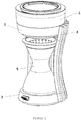
- FIG. 1 shows an isometric view of an embodiment of this invention.
- the coffee maker comprises a water tank ( 1 ) on a top housing ( 2 ) connected to a bottom housing ( 3 ) via a plurality of connecting elements ( 4 ) to form a space between the top housing ( 2 ) and bottom housing ( 3 ) to house a carafe ( 5 ).
- a rotating spout ( 6 ) At the bottom of the top housing is a rotating spout ( 6 ) to imitate manual pouring of hot water into the carafe.
- the carafe ( 5 ) comprises an upper part having a brewing cone ( 51 ) and a lower part for receiving brewed coffee. Coffee ground is placed inside the brewing cone and hot water from the rotating spout will pour over and percolates the coffee ground.
- the water tank ( 1 ) comprises a heating system, a valve and a temperature sensor, wherein when the temperature sensor detects water temperature in the water tank reaches a specified temperature, the heating system is turned off and the valve is opened to allow hot water to flow to the brewing cone via the rotating spout.
- Figure 2 is a cross-section of the coffee maker showing the spatial relationship of these components.
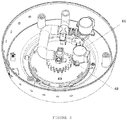
- Figure 3 shows the mechanism for controlling the rotating spout ( 6 ).
- a rotate spout drive motor ( 61 ) drives a rotate spout drive gear ( 62 ) which in turn drives a rotate spout gear ( 63 ) to cause the spout to rotate when the rotate spout drive motor ( 61 ) is turned on.
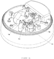
- Figure 4 shows a system ( 7 ) controlling water supply to the spout comprising a spout valve drive motor ( 71 ) for driving a spout valve cam ( 72 ) that pushes on a spout valve lever ( 73 ) to act on a spout valve body to control water flow.
- Actions of the heating system, valve system and rotating spout system are closely correlated so that water to a specified temperature in the water tank will be promptly released into the coffee ground in a manner similar to manual pour over.
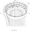
- FIG. 5 shows how the plurality of connecting elements connects to the top housing and lower housing.
- Each top or bottom housing will have a plurality of holes corresponding to each of the plurality of connecting elements.
- Each connecting element will have a hook-like feature (41) to be inserted into each of the holes in the top or bottom housing.
- Within the top or bottom housing is a piece of interlock (21, 31) that can be moved to fit nicely into the space inside the hook (4) of the connecting elements to lock them in place.
- This design removes the need for using a mould for the housing so that it is cheaper and easier to produce.
- the type of materials that can be chosen for the housing can be easily varied, for example, wooden strips can be used as the plurality of connecting elements. This will not be possible with conventional coffee maker designs. Due to the spacing between each connecting element, light can shine through the housing into the carafe and a user can observe the brewing process clearly.
Landscapes
- Engineering & Computer Science (AREA)
- Food Science & Technology (AREA)
- Apparatus For Making Beverages (AREA)
Description
- This invention relates generally to the field of coffee makers.
- Currently, there is no coffee makers that could reproduce manual pouring action over coffee ground when making pour over coffee. In fact, there is no electric coffee makers that could replicate manual pouring action over coffee ground.
- The housing of current coffee makers requires expensive procedures to make and tedious process to assemble. The housings usually do not allow light to pass through so that one could not easily observe the process when hot water flow through the coffee ground.
- Document
US 2014/272047 A1 discloses a coffee maker comprising a top housing connected to a bottom housing via a plurality of connecting elements such that the top housing is enacted above the bottom housing; a water tank positioned on top of the top housing; a carafe to be placed under said top housing, said carafe comprises an upper part having a brewing cone; and a rotating spout located at the bottom of said top housing and above said carafe for pouring hot water into said carafe. - To overcome the limitations of the existing coffee makers, this invention provides a pour over coffee maker with automatic pour over function.
- This invention provides a coffee maker as defined in
claim 1. - The invention provides a coffee maker comprising (i) a top housing (2) connected to a bottom housing (3) via a plurality of connecting elements (4) such that the top housing is enacted above the bottom housing, (ii) a water tank (1) positioned on top of the top housing, (iii) a carafe (5) to be placed under said top housing, said carafe comprises an upper part having a brewing cone (51), and (iv) a rotating spout (6) located at the bottom of said top housing and above said carafe for pouring hot water into said carafe.
- In one embodiment, the rotating spout of the present coffee maker is driven by a motor when a temperature sensor detects a specified temperature in the water tank. In one embodiment, the rotating spout is driven to rotate concentrically above said brewing cone.
- According to the invention, the connecting elements are connected to said top housing and bottom housing by an interlock system. Said locking system comprises (i) a hook-like feature (41) located on both ends of the connecting elements and (ii) a piece of interlock (21) located adjacent to a wall of the top housing or bottom housing.
-
-
Figure 1 shows an isometric view of an embodiment of this invention having a water tank (1) on a top housing (2) connected to a bottom housing (3) via a plurality of connecting elements (4) to form a space between the top housing (2) and bottom housing (3) to house a carafe (5). -
Figure 2 shows a cross-section of the coffee maker. At the bottom of the top housing is a rotating spout (6), and the upper part of the carafe comprises a brewing cone (51). -
Figure 3 shows a mechanism for controlling the rotating spout. A rotate spout drive motor (61) drives a first rotate spout drive gear (62) which in turn drives a second rotate spout gear (63) to cause the spout to rotate. -
Figure 4A shows a system (7) for controlling water supply to the rotating spout. A spout valve drive motor (71) drives a spout valve cam (72) that pushes on a spout valve lever (73) to act on a spout valve body (74). The valve is shown in an open position. -
Figure 4B shows the same system as inFigure 4A for controlling water supply to the rotating spout, with the valve in a closed position. -
Figure 5A shows an interlocking system for connecting the plurality of connecting elements (4) to the top housing (2) in unlocked position. A hook-like feature (41) is inserted into each of the holes on the wall of the top housing. Adjacent to the wall of the top housing is a piece of interlock (21). -
Figure 5B shows the same interlocking system as inFigure 5A in a locked position. -
Figure 5C shows an interlocking system for connecting the plurality of connecting elements (4) to the bottom housing (3) in an unlocked position. A hook-like feature (41) is inserted into each of the holes on the wall of the bottom housing. Adjacent to the wall of the bottom housing is a piece of interlock (31). -
Figure 5D shows the same interlocking system as inFigure 5C in a locked position. - In one embodiment, this invention provides a coffee maker having an easily assembled housing and rotating spout.
- The coffee maker of this invention comprises: a water tank (1) on a top housing (2) connected to a bottom housing (3); the bottom of the top housing comprises a rotating spout (6) ; the bottom housing (3) comprises a power switch and a control board; a carafe (5) configured to be placed on the bottom housing, wherein the carafe comprises a brewing cone (51) that can be removably attached to an upper part of the carafe; and a plurality of connecting elements each having two ends; wherein the connecting element connects to the top housing at one end and to the bottom housing at another end such that the top housing is enacted above the bottom housing.
- The connecting element is connected to the top housing and the bottom housing by an interlock system as shown in
Figures 5A-D . The interlock system comprises a structure on each of the two ends of the connecting elements for insertion into the top housing and the lower housing where an interlock structure will snug fit onto each of the structures on the connecting elements. The structure on the connecting element is a hook to be inserted into corresponding holes on the top housing and bottom housing. Each of the top housing and bottom housing has one or more pieces of interlock that are snug fitted to below the hooks for locking the connecting elements in place. - In one embodiment, interlocking the connecting elements with the top housing and bottom housing requires less time than assembling a traditional coffee maker housing.
- In one embodiment, the number, shape, and/or spacing of the connecting elements can be tailored to optimize the amount of light available for viewing the brewing process in the top part of the carafe.
- In one embodiment, the connecting element is made of wood, metal, glass, plastic, leather or die cast.
- In another embodiment, the connecting element is made of transparent material.
- In one embodiment, the connecting element is curved. In another embodiment, the connecting element is straight.
- In one embodiment, the brewing cone is enclosed in a case made of transparent material.
- In one embodiment, the carafe is made of transparent material.
- In one embodiment, the bottom housing comprises a keep warm system.
- In one embodiment, the rotating spout rotates concentrically above the brewing cone when water from the water tank is dispensed onto the brewing cone through the rotating spout.
- In one embodiment, the rotating spout comprises an outlet which opens horizontally.
- In one embodiment, the rotating spout comprises an outlet which opens diagonally.
- In one embodiment, the rotating spout is driven by a motor.
- In one embodiment, the water tank comprises a temperature sensor, wherein the rotating spout is driven by a motor when the temperature sensor detects a specified temperature in the water tank. In another embodiment, the specified temperature can be controlled by a user. In one embodiment, the water tank is placed on top of the brewing cone so that water at the specified temperature can be directly released onto ground coffee so as to meet stringent coffee brewing requirements such as SCAA.
- In one embodiment, the water tank is made of a transparent material.
- In one embodiment, the water tank comprises a heating system, a valve and a temperature sensor, wherein when the temperature sensor detects water temperature in the water tank reaches a specified temperature, the heating system is turned off and the valve is opened to allow hot water to flow to the brewing cone via the rotating spout.
- This invention provides a coffee maker with a rotating spout.
- In one embodiment, the coffee maker comprises:a water tank on a top housing and a rotating spout; a bottom housing comprising a brewing cone; wherein the rotating spout rotates concentrically above the brewing cone when water from the water tank is dispensed onto the brewing cone through the rotating spout.
- In one embodiment, the rotating spout comprises an outlet which opens horizontally.
- In one embodiment, the rotating spout comprises an outlet which opens diagonally.
- In one embodiment, the rotating spout is driven by a motor.
- In one embodiment, the water tank comprises a temperature sensor, wherein the motor drives the rotating spout when the temperature sensor detects a specified temperature in the water tank.
- In one embodiment, the water tank is made of a transparent material.
- In one embodiment, the brewing cone is made of a transparent material. In another embodiment, the brewing cone is made of plastic, steel or die cast.
- In one embodiment, the rotating spout is made of a transparent material. In another embodiment, the rotating spout is made of plastic, steel or die cast.
- In one embodiment, the water tank comprises a heating system, a valve and a temperature sensor, wherein, when the valve detects water temperature in the water tank reaches a specified temperature, the heating system is turned off and the valve opens so that hot water will flow to the brewing cone via the rotating spout.
- This invention also provides a coffee maker having an easily assembled housing.
- In one embodiment, the coffee maker comprises: a water tank on a top housing ; a bottom housing; a plurality of connecting elements each having two ends; wherein the connecting element connects to the upper structure at one end and the base structure at the other end such that the upper structure is enacted above the base structure.
- The connecting element is connected to the upper structure and the base structure by an interlock system as shown in
Figures 5A-D . - In one embodiment, the connecting element is made of wood, metal, glass, plastic, leather or die cast.
- In another embodiment, the connecting element is made of transparent material.
- In one embodiment, the connecting element is curved. In another embodiment, the connecting element is straight.
- In one embodiment, the coffee maker further comprises a brewing cone and a carafe that can be connected to form a single structure. In another embodiment, the brewing cone is made of transparent material. In yet another embodiment, the carafe is made of transparent material. In another embodiment, the brewing cone and carafe are connected to form a hour-glass structure.
- In one embodiment, the base structure comprises a keep warm system.
- In one embodiment, interlocking the connecting elements with the upper structure and lower structure via the interlock system requires less time than assembling a traditional coffee maker housing. The interlock system comprises a structure on each of the two ends of the connecting elements for insertion into the upper structure and the base structure where an interlock structure that snug fit onto each of the structures on the connecting elements. The structure on the connecting element is a hook to be inserted into corresponding holes on the upper and base structures. Each of the upper and base structures has one or more pieces of interlock that are snug fitted to below the hooks for locking the connecting elements in place.
- In one embodiment, the number, shape, spacing of the connecting elements can be tailored to optimize the amount of light entering the housing for viewing of the brewing process.
- The present invention provides a coffee maker comprising (i) a top housing (2) connected to a bottom housing (3) via a plurality of connecting elements (4) such that the top housing is enacted above the bottom housing, (ii) a water tank (1) positioned on top of the top housing, (iii) a carafe (5) to be placed under the top housing, the carafe comprises an upper part having a brewing cone (51), and (iv) a rotating spout (6) located at the bottom of the top housing and above the carafe for pouring hot water into the carafe. In one embodiment, the water tank is made of a transparent material. In another embodiment, the water tank comprises a heating system, a valve and a temperature sensor, wherein when the temperature sensor detects a specified temperature, the heating system is turned off and the valve is opened to allow hot water flowing via the rotating spout.
- In one embodiment, the rotating spout of the present coffee maker is driven by a motor when a temperature sensor detects a specified temperature in the water tank. In one embodiment, the rotating spout is driven to rotate concentrically above the brewing cone.
- In one embodiment, the rotating spout comprises an outlet which opens horizontally. In another embodiment, the rotating spout comprises an outlet which opens diagonally.
- In one embodiment, the bottom housing comprises a keep warm system.
- In one embodiment, the connecting elements are made of wood, metal, glass, plastic, leather or die cast. In another embodiment, the connecting elements are made of transparent material. The connecting elements can be curved or straight.
- The connecting elements are connected to the top housing and bottom housing by an interlock system. The locking system comprises (i) a hook-like feature (41) located on both ends of the connecting elements and (ii) a piece of interlock (21) located adjacent to a wall of the top housing or bottom housing.
- The invention provides a coffee maker comprising: a top housing (2) connected to a bottom housing (3) via a plurality of connecting elements (4) such that the top housing is enacted above the bottom housing; a water tank (1) positioned on top of the top housing; a carafe (5) to be placed under the top housing, the carafe comprises an upper part having a brewing cone (51); and a rotating spout (6) located at the bottom of the top housing and above the carafe for pouring hot water into the carafe.
- In one embodiment, the water tank is made of a transparent material.
- In one embodiment, the water tank comprises a heating system, a valve and a temperature sensor, wherein when the temperature sensor detects a specified temperature, the heating system is turned off and the valve is opened to allow hot water flowing via the rotating spout.
- In one embodiment, the rotating spout is driven by a motor when a temperature sensor detects a specified temperature in the water tank.
- In one embodiment, the rotating spout is driven to rotate concentrically above the brewing cone.
- In one embodiment, the rotating spout comprises an outlet which opens horizontally.
- In one embodiment, the rotating spout comprises an outlet which opens diagonally.
- In one embodiment, the bottom housing comprises a keep warm system.
- In one embodiment, the plurality of connecting elements are made of wood, metal, glass, plastic, leather or die cast.
- In one embodiment, the plurality of connecting elements are made of transparent material.
- In one embodiment, the plurality of connecting elements are curved.
- In one embodiment, the plurality of connecting elements are straight.
- The plurality of connecting elements are connected to the top housing and bottom housing by an interlock system. The interlock system comprises a hook-like feature (41) located on both ends of each of the plurality of connecting elements, a plurality of holes on the top housing and bottom housing corresponding to each of the plurality of connecting elements (4), and a piece of interlock (21) located adjacent to a wall of the top housing or bottom housing.
- The invention will be better understood by reference to the Example which follows, but those skilled in the art will readily appreciate that the specific examples are for illustrative purposes only and should not limit the scope of the invention which is defined by the claims which follow thereafter.
- It is to be noted that the transitional term "comprising", which is synonymous with "including", "containing" or "characterized by", is inclusive or open-ended and does not exclude additional, un-recited elements or method steps.
-
Figure 1 shows an isometric view of an embodiment of this invention. The coffee maker comprises a water tank (1) on a top housing (2) connected to a bottom housing (3) via a plurality of connecting elements (4) to form a space between the top housing (2) and bottom housing (3) to house a carafe (5). At the bottom of the top housing is a rotating spout (6) to imitate manual pouring of hot water into the carafe. The carafe (5) comprises an upper part having a brewing cone (51) and a lower part for receiving brewed coffee. Coffee ground is placed inside the brewing cone and hot water from the rotating spout will pour over and percolates the coffee ground. The water tank (1) comprises a heating system, a valve and a temperature sensor, wherein when the temperature sensor detects water temperature in the water tank reaches a specified temperature, the heating system is turned off and the valve is opened to allow hot water to flow to the brewing cone via the rotating spout.Figure 2 is a cross-section of the coffee maker showing the spatial relationship of these components. -
Figure 3 shows the mechanism for controlling the rotating spout (6). A rotate spout drive motor (61) drives a rotate spout drive gear (62) which in turn drives a rotate spout gear (63) to cause the spout to rotate when the rotate spout drive motor (61) is turned on. -
Figure 4 shows a system (7) controlling water supply to the spout comprising a spout valve drive motor (71) for driving a spout valve cam (72) that pushes on a spout valve lever (73) to act on a spout valve body to control water flow. - Actions of the heating system, valve system and rotating spout system are closely correlated so that water to a specified temperature in the water tank will be promptly released into the coffee ground in a manner similar to manual pour over.
-
Figure 5 shows how the plurality of connecting elements connects to the top housing and lower housing. Each top or bottom housing will have a plurality of holes corresponding to each of the plurality of connecting elements. Each connecting element will have a hook-like feature (41) to be inserted into each of the holes in the top or bottom housing. Within the top or bottom housing is a piece of interlock (21, 31) that can be moved to fit nicely into the space inside the hook (4) of the connecting elements to lock them in place. This design removes the need for using a mould for the housing so that it is cheaper and easier to produce. The type of materials that can be chosen for the housing can be easily varied, for example, wooden strips can be used as the plurality of connecting elements. This will not be possible with conventional coffee maker designs. Due to the spacing between each connecting element, light can shine through the housing into the carafe and a user can observe the brewing process clearly.
Claims (12)
- A coffee maker comprisinga. a top housing (2) connected to a bottom housing (3) via a plurality of connecting elements (4) such that the top housing is enacted above the bottom housing;b. a water tank (1) positioned on top of the top housing;c. a carafe (5) to be placed under said top housing, said carafe comprises an upper part having a brewing cone (51); andd. a rotating spout (6) located at the bottom of said top housing and above said carafe for pouring hot water into said carafe, characterized in that:
said plurality of connecting elements (4) are connected to said top housing and bottom housing by an interlock system; said interlock system comprises a hook-like feature (41) located on both ends of each of said plurality of connecting elements, a plurality of holes on said top housing and bottom housing corresponding to each of the plurality of connecting elements (4), and a piece of interlock (21) located adjacent to a wall of said top housing or bottom housing. - The coffee maker of claim 1, wherein the water tank is made of a transparent material.
- The coffee maker of claim 1, wherein the water tank comprises a heating system, a valve and a temperature sensor, wherein when said temperature sensor detects a specified temperature, said heating system is turned off and said valve is opened to allow hot water flowing via said rotating spout.
- The coffee maker of claim 1, wherein said rotating spout is driven by a motor when a temperature sensor detects a specified temperature in said water tank.
- The coffee maker of claim 1, wherein said rotating spout is driven to rotate concentrically above said brewing cone.
- The coffee maker of claim 1, wherein said rotating spout comprises an outlet which opens horizontally.
- The coffee maker of claim 1, wherein said rotating spout comprises an outlet which opens diagonally.
- The coffee maker of claim 1, wherein said bottom housing comprises a keep warm system.
- The coffee maker of claim 1, wherein said plurality of connecting elements are made of wood, metal, glass, plastic, leather or die cast.
- The coffee maker of claim 1, wherein said plurality of connecting elements are made of transparent material.
- The coffee maker of claim 1, wherein said plurality of connecting elements are curved.
- The coffee maker of claim 1, wherein said plurality of connecting elements are straight.
Applications Claiming Priority (2)
| Application Number | Priority Date | Filing Date | Title |
|---|---|---|---|
| US201762472672P | 2017-03-17 | 2017-03-17 | |
| PCT/IB2018/051768 WO2018167726A1 (en) | 2017-03-17 | 2018-03-16 | Automatic pour over coffee maker |
Publications (3)
| Publication Number | Publication Date |
|---|---|
| EP3595496A1 EP3595496A1 (en) | 2020-01-22 |
| EP3595496A4 EP3595496A4 (en) | 2020-09-30 |
| EP3595496B1 true EP3595496B1 (en) | 2021-10-06 |
Family
ID=63521872
Family Applications (1)
| Application Number | Title | Priority Date | Filing Date |
|---|---|---|---|
| EP18767003.9A Active EP3595496B1 (en) | 2017-03-17 | 2018-03-16 | Automatic pour over coffee maker |
Country Status (3)
| Country | Link |
|---|---|
| EP (1) | EP3595496B1 (en) |
| CN (1) | CN110799069B (en) |
| WO (1) | WO2018167726A1 (en) |
Families Citing this family (2)
| Publication number | Priority date | Publication date | Assignee | Title |
|---|---|---|---|---|
| CN211883424U (en) * | 2018-12-27 | 2020-11-10 | 万物智得股份有限公司 | Manual coffee recording system |
| TWI792959B (en) * | 2022-03-25 | 2023-02-11 | 城市學校財團法人臺北城市科技大學 | A tea maker with the function of pouring water by imitating an expert's hand |
Family Cites Families (24)
| Publication number | Priority date | Publication date | Assignee | Title |
|---|---|---|---|---|
| US6343542B1 (en) * | 2000-10-26 | 2002-02-05 | Shun Tsung Shen | Coffee-making container |
| US7753223B2 (en) * | 2005-05-17 | 2010-07-13 | Vita-Mix Corporation | Interlocking blender container, cover and cover plug |
| CN2810437Y (en) * | 2005-05-25 | 2006-08-30 | 张浩锋 | Improved structure of a coffee brewing machine |
| US20080148956A1 (en) * | 2006-12-20 | 2008-06-26 | Maurer Scott D | Coffee maker |
| CN201523971U (en) * | 2009-11-30 | 2010-07-14 | 东莞市步步高家用电器有限公司 | Electric pressure cooker with interlocking of cover closing in place and timing switch |
| CN102613916A (en) * | 2011-01-31 | 2012-08-01 | 阳光有限责任公司 | Food processing apparatus and receptacle thereof |
| KR101281650B1 (en) * | 2011-08-26 | 2013-07-03 | 경북대학교 산학협력단 | Coffee machine |
| EP2592013A1 (en) * | 2011-11-09 | 2013-05-15 | Carlsberg Breweries A/S | Beverage bottle with a re-sealable closure having a cam axle |
| CN202355234U (en) * | 2011-12-11 | 2012-08-01 | 王永光 | Electric heating cooking tool |
| US20130233952A1 (en) * | 2012-03-08 | 2013-09-12 | Hamilton Beach Brands, Inc. | Kitchen Appliance for Processing Foodstuff and Method of Operating Same |
| WO2014057428A2 (en) * | 2012-10-09 | 2014-04-17 | Electrical & Electronics Ltd. | Beverage temperature optimizer machine |
| US9930989B2 (en) * | 2013-03-14 | 2018-04-03 | Spectrum Brands, Inc. | Apparatus for brewing beverages |
| KR101570162B1 (en) * | 2013-10-31 | 2015-11-19 | 이병욱 | Coffe dripper for controlling the coffee brewing time |
| ITRM20130619A1 (en) * | 2013-11-11 | 2015-05-12 | Ides Dev Company Ltd N Ota In Commerc | DEVICE FOR THE PREPARATION OF A EMULSIFIED HOT DRINK |
| KR101489687B1 (en) * | 2014-01-09 | 2015-02-04 | 강동진 | Coffee drip machine |
| KR101468906B1 (en) * | 2014-04-15 | 2014-12-05 | 최선호 | Auto Coffee Drip Apparatus |
| CN103919467A (en) * | 2014-04-30 | 2014-07-16 | 杨尚林 | Intelligent beverage supplying machine |
| US10123650B2 (en) * | 2015-02-06 | 2018-11-13 | Whirlpool Corporation | Vacuum coffee maker with magnetic coupling system |
| CN204483871U (en) * | 2015-03-04 | 2015-07-22 | 浙江绍兴苏泊尔生活电器有限公司 | Capsule pick and place device and tea making machine |
| CN205031059U (en) * | 2015-08-21 | 2016-02-17 | 佛山市顺德区宏泽电器制造有限公司 | Full -automatic spiral dashes and steeps novel high temperature coffee machine |
| CN105231822A (en) * | 2015-10-08 | 2016-01-13 | 广东新宝电器股份有限公司 | Coffee pot and method for making coffee |
| CN105662150A (en) * | 2016-03-14 | 2016-06-15 | 江门市凯立信电气科技有限公司 | Machine capable of imitating human hands to make coffee |
| CN105640337A (en) * | 2016-03-14 | 2016-06-08 | 江门市凯立信电气科技有限公司 | Rotary coffee making machine |
| CN106377161A (en) * | 2016-10-28 | 2017-02-08 | 成都格瑞思文化传播有限公司 | Coffee brewing device |
-
2018
- 2018-03-16 CN CN201880032227.0A patent/CN110799069B/en active Active
- 2018-03-16 WO PCT/IB2018/051768 patent/WO2018167726A1/en not_active Ceased
- 2018-03-16 EP EP18767003.9A patent/EP3595496B1/en active Active
Also Published As
| Publication number | Publication date |
|---|---|
| WO2018167726A1 (en) | 2018-09-20 |
| CN110799069B (en) | 2021-08-27 |
| CN110799069A (en) | 2020-02-14 |
| EP3595496A4 (en) | 2020-09-30 |
| EP3595496A1 (en) | 2020-01-22 |
Similar Documents
| Publication | Publication Date | Title |
|---|---|---|
| KR101693261B1 (en) | Automatic drip coffie | |
| US4056050A (en) | Coffeemaker with brew strength control | |
| CN101557741B (en) | tea maker | |
| KR100897948B1 (en) | Drip Coffee & Tea Maker | |
| US8091470B2 (en) | Machine for filtered coffee with shutter opening | |
| CN101720195A (en) | Method and apparatus for brewing hot beverages | |
| KR100958453B1 (en) | Drip Coffee & Tea Maker | |
| CN102762135A (en) | Heated liquid vessels and electrical appliances | |
| CN108309054A (en) | Multifunctional coffee-making machine | |
| CN105030068A (en) | Auto coffee drip apparatus | |
| DE202011051712U1 (en) | Semi-automatic tea maker | |
| CN100531631C (en) | Tea water pouring device and method for pouring tea water | |
| EP2906088B1 (en) | Beverage temperature optimizer machine | |
| WO2018167726A1 (en) | Automatic pour over coffee maker | |
| CN101862137A (en) | Fryer with rotatable frying cage | |
| CN201727397U (en) | A fryer with a rotatable frying cage | |
| CN201039925Y (en) | Tea pouring device | |
| US11406218B2 (en) | Automatic pour over coffee maker | |
| US10555637B2 (en) | Brewer with temperature responsive control valve | |
| HK40025039B (en) | Automatic pour over coffee maker | |
| HK40025039A (en) | Automatic pour over coffee maker | |
| US7661353B2 (en) | Hot beverage maker | |
| EP4302657A1 (en) | A coffee maker | |
| JP2007054611A (en) | Beverage maker | |
| JP2007054603A (en) | Beverage maker |
Legal Events
| Date | Code | Title | Description |
|---|---|---|---|
| STAA | Information on the status of an ep patent application or granted ep patent |
Free format text: STATUS: THE INTERNATIONAL PUBLICATION HAS BEEN MADE |
|
| PUAI | Public reference made under article 153(3) epc to a published international application that has entered the european phase |
Free format text: ORIGINAL CODE: 0009012 |
|
| STAA | Information on the status of an ep patent application or granted ep patent |
Free format text: STATUS: REQUEST FOR EXAMINATION WAS MADE |
|
| 17P | Request for examination filed |
Effective date: 20191016 |
|
| AK | Designated contracting states |
Kind code of ref document: A1 Designated state(s): AL AT BE BG CH CY CZ DE DK EE ES FI FR GB GR HR HU IE IS IT LI LT LU LV MC MK MT NL NO PL PT RO RS SE SI SK SM TR |
|
| AX | Request for extension of the european patent |
Extension state: BA ME |
|
| DAV | Request for validation of the european patent (deleted) | ||
| DAX | Request for extension of the european patent (deleted) | ||
| A4 | Supplementary search report drawn up and despatched |
Effective date: 20200901 |
|
| RIC1 | Information provided on ipc code assigned before grant |
Ipc: A47J 31/02 20060101AFI20200826BHEP Ipc: A47J 31/46 20060101ALI20200826BHEP |
|
| GRAP | Despatch of communication of intention to grant a patent |
Free format text: ORIGINAL CODE: EPIDOSNIGR1 |
|
| STAA | Information on the status of an ep patent application or granted ep patent |
Free format text: STATUS: GRANT OF PATENT IS INTENDED |
|
| INTG | Intention to grant announced |
Effective date: 20210429 |
|
| RIN1 | Information on inventor provided before grant (corrected) |
Inventor name: CHEN, YUEN CHIN ANDREW Inventor name: WONG, WAI MING RAYMOND Inventor name: LEUNG, TAK FUNG DICK Inventor name: CHENG, PUI YIN AMY DECEM Inventor name: TAY, KOK LEONG JEREMY |
|
| GRAS | Grant fee paid |
Free format text: ORIGINAL CODE: EPIDOSNIGR3 |
|
| GRAA | (expected) grant |
Free format text: ORIGINAL CODE: 0009210 |
|
| STAA | Information on the status of an ep patent application or granted ep patent |
Free format text: STATUS: THE PATENT HAS BEEN GRANTED |
|
| AK | Designated contracting states |
Kind code of ref document: B1 Designated state(s): AL AT BE BG CH CY CZ DE DK EE ES FI FR GB GR HR HU IE IS IT LI LT LU LV MC MK MT NL NO PL PT RO RS SE SI SK SM TR |
|
| REG | Reference to a national code |
Ref country code: GB Ref legal event code: FG4D |
|
| REG | Reference to a national code |
Ref country code: CH Ref legal event code: EP Ref country code: AT Ref legal event code: REF Ref document number: 1435485 Country of ref document: AT Kind code of ref document: T Effective date: 20211015 |
|
| REG | Reference to a national code |
Ref country code: IE Ref legal event code: FG4D |
|
| REG | Reference to a national code |
Ref country code: DE Ref legal event code: R096 Ref document number: 602018024721 Country of ref document: DE |
|
| REG | Reference to a national code |
Ref country code: LT Ref legal event code: MG9D |
|
| REG | Reference to a national code |
Ref country code: NL Ref legal event code: MP Effective date: 20211006 |
|
| REG | Reference to a national code |
Ref country code: AT Ref legal event code: MK05 Ref document number: 1435485 Country of ref document: AT Kind code of ref document: T Effective date: 20211006 |
|
| PG25 | Lapsed in a contracting state [announced via postgrant information from national office to epo] |
Ref country code: RS Free format text: LAPSE BECAUSE OF FAILURE TO SUBMIT A TRANSLATION OF THE DESCRIPTION OR TO PAY THE FEE WITHIN THE PRESCRIBED TIME-LIMIT Effective date: 20211006 Ref country code: LT Free format text: LAPSE BECAUSE OF FAILURE TO SUBMIT A TRANSLATION OF THE DESCRIPTION OR TO PAY THE FEE WITHIN THE PRESCRIBED TIME-LIMIT Effective date: 20211006 Ref country code: FI Free format text: LAPSE BECAUSE OF FAILURE TO SUBMIT A TRANSLATION OF THE DESCRIPTION OR TO PAY THE FEE WITHIN THE PRESCRIBED TIME-LIMIT Effective date: 20211006 Ref country code: BG Free format text: LAPSE BECAUSE OF FAILURE TO SUBMIT A TRANSLATION OF THE DESCRIPTION OR TO PAY THE FEE WITHIN THE PRESCRIBED TIME-LIMIT Effective date: 20220106 Ref country code: AT Free format text: LAPSE BECAUSE OF FAILURE TO SUBMIT A TRANSLATION OF THE DESCRIPTION OR TO PAY THE FEE WITHIN THE PRESCRIBED TIME-LIMIT Effective date: 20211006 |
|
| PG25 | Lapsed in a contracting state [announced via postgrant information from national office to epo] |
Ref country code: IS Free format text: LAPSE BECAUSE OF FAILURE TO SUBMIT A TRANSLATION OF THE DESCRIPTION OR TO PAY THE FEE WITHIN THE PRESCRIBED TIME-LIMIT Effective date: 20220206 Ref country code: SE Free format text: LAPSE BECAUSE OF FAILURE TO SUBMIT A TRANSLATION OF THE DESCRIPTION OR TO PAY THE FEE WITHIN THE PRESCRIBED TIME-LIMIT Effective date: 20211006 Ref country code: PT Free format text: LAPSE BECAUSE OF FAILURE TO SUBMIT A TRANSLATION OF THE DESCRIPTION OR TO PAY THE FEE WITHIN THE PRESCRIBED TIME-LIMIT Effective date: 20220207 Ref country code: PL Free format text: LAPSE BECAUSE OF FAILURE TO SUBMIT A TRANSLATION OF THE DESCRIPTION OR TO PAY THE FEE WITHIN THE PRESCRIBED TIME-LIMIT Effective date: 20211006 Ref country code: NO Free format text: LAPSE BECAUSE OF FAILURE TO SUBMIT A TRANSLATION OF THE DESCRIPTION OR TO PAY THE FEE WITHIN THE PRESCRIBED TIME-LIMIT Effective date: 20220106 Ref country code: NL Free format text: LAPSE BECAUSE OF FAILURE TO SUBMIT A TRANSLATION OF THE DESCRIPTION OR TO PAY THE FEE WITHIN THE PRESCRIBED TIME-LIMIT Effective date: 20211006 Ref country code: LV Free format text: LAPSE BECAUSE OF FAILURE TO SUBMIT A TRANSLATION OF THE DESCRIPTION OR TO PAY THE FEE WITHIN THE PRESCRIBED TIME-LIMIT Effective date: 20211006 Ref country code: HR Free format text: LAPSE BECAUSE OF FAILURE TO SUBMIT A TRANSLATION OF THE DESCRIPTION OR TO PAY THE FEE WITHIN THE PRESCRIBED TIME-LIMIT Effective date: 20211006 Ref country code: GR Free format text: LAPSE BECAUSE OF FAILURE TO SUBMIT A TRANSLATION OF THE DESCRIPTION OR TO PAY THE FEE WITHIN THE PRESCRIBED TIME-LIMIT Effective date: 20220107 Ref country code: ES Free format text: LAPSE BECAUSE OF FAILURE TO SUBMIT A TRANSLATION OF THE DESCRIPTION OR TO PAY THE FEE WITHIN THE PRESCRIBED TIME-LIMIT Effective date: 20211006 |
|
| REG | Reference to a national code |
Ref country code: DE Ref legal event code: R097 Ref document number: 602018024721 Country of ref document: DE |
|
| PG25 | Lapsed in a contracting state [announced via postgrant information from national office to epo] |
Ref country code: SM Free format text: LAPSE BECAUSE OF FAILURE TO SUBMIT A TRANSLATION OF THE DESCRIPTION OR TO PAY THE FEE WITHIN THE PRESCRIBED TIME-LIMIT Effective date: 20211006 Ref country code: SK Free format text: LAPSE BECAUSE OF FAILURE TO SUBMIT A TRANSLATION OF THE DESCRIPTION OR TO PAY THE FEE WITHIN THE PRESCRIBED TIME-LIMIT Effective date: 20211006 Ref country code: RO Free format text: LAPSE BECAUSE OF FAILURE TO SUBMIT A TRANSLATION OF THE DESCRIPTION OR TO PAY THE FEE WITHIN THE PRESCRIBED TIME-LIMIT Effective date: 20211006 Ref country code: EE Free format text: LAPSE BECAUSE OF FAILURE TO SUBMIT A TRANSLATION OF THE DESCRIPTION OR TO PAY THE FEE WITHIN THE PRESCRIBED TIME-LIMIT Effective date: 20211006 Ref country code: DK Free format text: LAPSE BECAUSE OF FAILURE TO SUBMIT A TRANSLATION OF THE DESCRIPTION OR TO PAY THE FEE WITHIN THE PRESCRIBED TIME-LIMIT Effective date: 20211006 Ref country code: CZ Free format text: LAPSE BECAUSE OF FAILURE TO SUBMIT A TRANSLATION OF THE DESCRIPTION OR TO PAY THE FEE WITHIN THE PRESCRIBED TIME-LIMIT Effective date: 20211006 |
|
| PLBE | No opposition filed within time limit |
Free format text: ORIGINAL CODE: 0009261 |
|
| STAA | Information on the status of an ep patent application or granted ep patent |
Free format text: STATUS: NO OPPOSITION FILED WITHIN TIME LIMIT |
|
| 26N | No opposition filed |
Effective date: 20220707 |
|
| PG25 | Lapsed in a contracting state [announced via postgrant information from national office to epo] |
Ref country code: MC Free format text: LAPSE BECAUSE OF FAILURE TO SUBMIT A TRANSLATION OF THE DESCRIPTION OR TO PAY THE FEE WITHIN THE PRESCRIBED TIME-LIMIT Effective date: 20211006 Ref country code: AL Free format text: LAPSE BECAUSE OF FAILURE TO SUBMIT A TRANSLATION OF THE DESCRIPTION OR TO PAY THE FEE WITHIN THE PRESCRIBED TIME-LIMIT Effective date: 20211006 |
|
| REG | Reference to a national code |
Ref country code: CH Ref legal event code: PL |
|
| PG25 | Lapsed in a contracting state [announced via postgrant information from national office to epo] |
Ref country code: SI Free format text: LAPSE BECAUSE OF FAILURE TO SUBMIT A TRANSLATION OF THE DESCRIPTION OR TO PAY THE FEE WITHIN THE PRESCRIBED TIME-LIMIT Effective date: 20211006 |
|
| REG | Reference to a national code |
Ref country code: BE Ref legal event code: MM Effective date: 20220331 |
|
| PG25 | Lapsed in a contracting state [announced via postgrant information from national office to epo] |
Ref country code: LU Free format text: LAPSE BECAUSE OF NON-PAYMENT OF DUE FEES Effective date: 20220316 Ref country code: LI Free format text: LAPSE BECAUSE OF NON-PAYMENT OF DUE FEES Effective date: 20220331 Ref country code: IE Free format text: LAPSE BECAUSE OF NON-PAYMENT OF DUE FEES Effective date: 20220316 Ref country code: CH Free format text: LAPSE BECAUSE OF NON-PAYMENT OF DUE FEES Effective date: 20220331 |
|
| PG25 | Lapsed in a contracting state [announced via postgrant information from national office to epo] |
Ref country code: BE Free format text: LAPSE BECAUSE OF NON-PAYMENT OF DUE FEES Effective date: 20220331 |
|
| PGFP | Annual fee paid to national office [announced via postgrant information from national office to epo] |
Ref country code: FR Payment date: 20230328 Year of fee payment: 6 |
|
| PG25 | Lapsed in a contracting state [announced via postgrant information from national office to epo] |
Ref country code: IT Free format text: LAPSE BECAUSE OF FAILURE TO SUBMIT A TRANSLATION OF THE DESCRIPTION OR TO PAY THE FEE WITHIN THE PRESCRIBED TIME-LIMIT Effective date: 20211006 |
|
| PG25 | Lapsed in a contracting state [announced via postgrant information from national office to epo] |
Ref country code: MK Free format text: LAPSE BECAUSE OF FAILURE TO SUBMIT A TRANSLATION OF THE DESCRIPTION OR TO PAY THE FEE WITHIN THE PRESCRIBED TIME-LIMIT Effective date: 20211006 Ref country code: CY Free format text: LAPSE BECAUSE OF FAILURE TO SUBMIT A TRANSLATION OF THE DESCRIPTION OR TO PAY THE FEE WITHIN THE PRESCRIBED TIME-LIMIT Effective date: 20211006 |
|
| PGFP | Annual fee paid to national office [announced via postgrant information from national office to epo] |
Ref country code: DE Payment date: 20240313 Year of fee payment: 7 |
|
| PG25 | Lapsed in a contracting state [announced via postgrant information from national office to epo] |
Ref country code: HU Free format text: LAPSE BECAUSE OF FAILURE TO SUBMIT A TRANSLATION OF THE DESCRIPTION OR TO PAY THE FEE WITHIN THE PRESCRIBED TIME-LIMIT; INVALID AB INITIO Effective date: 20180316 |
|
| PG25 | Lapsed in a contracting state [announced via postgrant information from national office to epo] |
Ref country code: MT Free format text: LAPSE BECAUSE OF FAILURE TO SUBMIT A TRANSLATION OF THE DESCRIPTION OR TO PAY THE FEE WITHIN THE PRESCRIBED TIME-LIMIT Effective date: 20211006 |
|
| PG25 | Lapsed in a contracting state [announced via postgrant information from national office to epo] |
Ref country code: FR Free format text: LAPSE BECAUSE OF NON-PAYMENT OF DUE FEES Effective date: 20240331 |
|
| PG25 | Lapsed in a contracting state [announced via postgrant information from national office to epo] |
Ref country code: FR Free format text: LAPSE BECAUSE OF NON-PAYMENT OF DUE FEES Effective date: 20240331 |
|
| PGFP | Annual fee paid to national office [announced via postgrant information from national office to epo] |
Ref country code: GB Payment date: 20250306 Year of fee payment: 8 |
|
| REG | Reference to a national code |
Ref country code: DE Ref legal event code: R119 Ref document number: 602018024721 Country of ref document: DE |
|
| PG25 | Lapsed in a contracting state [announced via postgrant information from national office to epo] |
Ref country code: TR Free format text: LAPSE BECAUSE OF FAILURE TO SUBMIT A TRANSLATION OF THE DESCRIPTION OR TO PAY THE FEE WITHIN THE PRESCRIBED TIME-LIMIT Effective date: 20211006 |
|
| PG25 | Lapsed in a contracting state [announced via postgrant information from national office to epo] |
Ref country code: DE Free format text: LAPSE BECAUSE OF NON-PAYMENT OF DUE FEES Effective date: 20251001 |