EP3595333A1 - Mems device - Google Patents
Mems device Download PDFInfo
- Publication number
- EP3595333A1 EP3595333A1 EP18183013.4A EP18183013A EP3595333A1 EP 3595333 A1 EP3595333 A1 EP 3595333A1 EP 18183013 A EP18183013 A EP 18183013A EP 3595333 A1 EP3595333 A1 EP 3595333A1
- Authority
- EP
- European Patent Office
- Prior art keywords
- auxetic
- membrane
- accordance
- mems device
- structural elements
- Prior art date
- Legal status (The legal status is an assumption and is not a legal conclusion. Google has not performed a legal analysis and makes no representation as to the accuracy of the status listed.)
- Withdrawn
Links
Images




Classifications
-
- H—ELECTRICITY
- H04—ELECTRIC COMMUNICATION TECHNIQUE
- H04R—LOUDSPEAKERS, MICROPHONES, GRAMOPHONE PICK-UPS OR LIKE ACOUSTIC ELECTROMECHANICAL TRANSDUCERS; ELECTRIC HEARING AIDS; PUBLIC ADDRESS SYSTEMS
- H04R19/00—Electrostatic transducers
- H04R19/04—Microphones
-
- H—ELECTRICITY
- H04—ELECTRIC COMMUNICATION TECHNIQUE
- H04R—LOUDSPEAKERS, MICROPHONES, GRAMOPHONE PICK-UPS OR LIKE ACOUSTIC ELECTROMECHANICAL TRANSDUCERS; ELECTRIC HEARING AIDS; PUBLIC ADDRESS SYSTEMS
- H04R19/00—Electrostatic transducers
- H04R19/005—Electrostatic transducers using semiconductor materials
Definitions
- Embodiments of the present disclosure relate to an MEMS device, to a sound transducer comprising said MEMS device, and to a manufacturing method of said MEMS device.
- MEMS devices allow realizing sound transducers, like loudspeakers or microphones, for example.
- sound transducers typically comprise a membrane which can be excited to oscillate externally or by means of sound in the surroundings (microphone), or be excited to oscillate electrically (for realizing a loudspeaker).
- membranes are formed by means of semiconductor technologies in or on a substrate.
- the sensitivity of the entire system is the sensitivity of the entire system.
- the sensitivity of the microphone can be improved by reducing the membrane thickness or by increasing the membrane area (diameter). Both ways have disadvantages. Increasing the size of a membrane is expensive and with reduction of the membrane thickness the microphones lose mechanical stability, in particular during manufacturing and in the application.
- an MEMS device comprising a membrane configured to oscillate (when excited externally or excited electrically).
- the membrane comprises an auxetic structure at least in portions thereof.
- an auxetic structure is a structure which, as a consequence of expansion, e.g. expansion of the membrane in a first (lateral) direction, expands of its own accord in a second, e.g. orthogonal (lateral) direction, and/or wherein the thickness of the membrane increases as a consequence of the expansion in the first direction.
- auxetic structures also exhibit comparable characteristics, which means that, when compressing the membrane in the first (lateral) direction, the membrane will be compressed of its own accord or due to the auxetic structure in the second, e.g.
- the auxetic structure comprises a plurality of auxetic structural elements, like identical or mutually similar structural elements.
- Each of these auxetic structural elements may be formed by an area (in parallel to the membrane) enclosed or defined by four, preferably arched, lateral boundaries (like profile structures, steps or trenches).
- these (preferably identical) structural elements are arranged in one or several rows (row after row in order to cover the membrane region at least in an area portion).
- the plurality of the auxetic structural elements in one row are mutually adjacent so that a first and a third one exhibit an identical orientation, wherein a second auxetic structural element arranged therebetween is rotated compared to the first and third auxetic structural elements, like rotated by 90°.
- the individual auxetic structural elements can be different within a membrane. I.e. the auxetic structure comprises a plurality of auxetic structural elements, wherein at least two auxetic structural elements differ from each other.
- each auxetic structural element is formed by two opposite lateral boundaries (i.e. along the membrane plane) and two further opposite lateral boundaries
- each auxetic structural element forms a kind of quadrangle, for example, wherein, in accordance with embodiments, the lateral opposite boundaries and the further lateral opposite boundaries are bent (the result not being a classical quadrangle).
- the arched opposite lateral boundaries may be formed as follows: each auxetic structural element is confined by two opposite lateral concave and two opposite lateral convex boundaries so that the auxetic area element of the respective auxetic structural element is enclosed by the two concave and the two convex boundaries.
- the concave boundary for the central (rotated) lateral structural element also represents the convex boundary for the adjacent (non-rotated) structural element.
- the auxetic structural elements can be also different within a membrane.
- the orientation could be rotational symmetric and/or the size can be scaled with respect to the position inside the membrane.
- each lateral boundary is formed by a raised profile, like a dome from the substrate plane, or by a trench profile.
- the raised profile or the trench profile divides the plurality of auxetic structural elements among one another.
- the membrane thickness only varies minimally across the profile, i.e. only at the transitions, wherein, in the region where the profile is formed, the membrane thickness may exemplarily exhibit the same thickness as the membrane thickness in the region of the area element (subsequently referred to as auxetic area element, which is enclosed by the lateral boundaries) of the auxetic structural element.
- the plurality of the auxetic structural elements each comprise an auxetic area element, wherein the auxetic area elements extend in parallel to or along the membrane plane.
- two of the auxetic area elements are arranged in two different planes.
- each auxetic structural element comprises an auxetic area element enclosed by the (four) boundaries
- the auxetic area elements it would be feasible for the auxetic area elements to be positioned alternatingly in a top and a bottom plane.
- the lateral boundary here is formed by a step forming a transition from one auxetic area element of one of the plurality of auxetic structural elements relative to another auxetic area element of an adjacent one of the plurality of auxetic structural elements.
- the lateral boundary is formed by a step
- the lateral boundary is formed by a profile or a trench profile
- the step or profile/trench is formed by the membrane itself.
- a sound transducer comprising an MEMS device as defined above.
- the sound transducer may form a microphone configured to be excited to oscillate when excited by sound from the surroundings and to output an electrical signal which depends on the sound.
- Fig. 1 shows an MEMS device 10, like a sound transducer in the form of a loudspeaker or a microphone, for example.
- This MEMS device 10 comprises a membrane 12 which is exemplarily formed in the substrate 14 of the MEMS device 10.
- the membrane 12 comprises an auxetic structure 16.
- This auxetic structure may, for example, be applied onto the membrane 12, or the membrane 12 may be formed such that the auxetic structure is formed in the membrane, wherein the latter will be assumed for the following discussion.
- the auxetic structure 16 is implemented by the membrane 12 being structured.
- the structuring 16p is, for example, formed by impressing a profile 16p into the membrane 12.
- the structuring is performed such that the membrane comprises a plurality of profiles extending laterally in two (crossing) directions, like a grid, along the membrane.
- An auxetic area element 16f each which is enclosed by the profile 16p on four sides is formed in the meshes of the "grid", thereby forming four corners at the points of contact of the profiles 16p.
- the profiles 16p border the auxetic area elements 16f laterally (lateral boundaries along the membrane 12 or along the respective plane).
- the profiles 16p/boundary lines are preferably (but not necessarily) curved.
- the membrane 12 having the auxetic structure 16 allows an extension of the membrane 12 in a first direction (cf. direction x), resulting in the membrane to also expand in a second direction (like, for example, direction y, orthogonal to direction x).
- a second direction like, for example, direction y, orthogonal to direction x.
- the membrane 12 it would also be conceivable for the membrane 12 to vary, like increase, in its thickness (cf. z direction) as a consequence of an expansion in the x direction.
- this characteristic which is provided by the auxetic structure 16 results in the membrane 12 being more flexible.
- the membrane 12 by applying the auxetic structure 16 on the surface of the membrane 12, for example, or by structuring the membrane 12 in the form of an auxetic structure, the membrane generally, or in portions, exhibits higher a flexibility.
- the MEMS device 10 is, for example, used as a microphone
- higher a sensitivity of the microphone 10 is achieved by the increase in flexibility of the membrane 12.
- the membrane 12 is considerably more robust to mechanical overstress, like in the case of dropping it.
- auxetic structures will be discussed below referring to Figs. 2a-h .
- Fig. 2a shows an auxetic structure 16 comprising boundaries 16g bordering the auxetic area element 16f and extending laterally on the plane.
- auxetic structure The action mechanism of such an auxetic structure will be discussed referring to Fig. 2b .
- the auxetic structural element 16f* comprises two concave lateral boundaries 16fc* and two convex boundaries 16fcx*.
- the deformation which is illustrated by the arrows, exemplarily acts on the concave boundaries 16fcx*, resulting in the same to be compressed, as is illustrated in broken lines. Consequently, the concave boundaries are also compressed towards the interior by the points of contact of the concave and convex boundaries 16fcx* and 16fc*, as is illustrated in broken lines.
- Fig. 2c the broken line illustrates the original shape with no external force applied, wherein the area having the continuous line illustrates compression of the auxetic structure 16f*.
- Fig. 2d where the identical area is compressed in the y direction, however with no auxetic structure, the result of this, however, being an expansion in the x direction.
- auxetic structures the same principle also applies in the case of an expansion, i.e. in the case of a tensile force in the y direction, the result being an expansion of the area in the x direction.
- the deformations within the auxetic structure are illustrated in Fig. 2g for the broken-line area of Fig. 2c in the compressed state.
- Fig. 2g illustrates an auxetic structure 16 which is, for example, employed in the illustrative example of Fig. 2c .
- This auxetic structure 16 is basically implemented to be two-dimensional. However, there are also three-dimensional auxetic structures, as is, for example, illustrated in Fig. 2h .
- the membrane discussed referring to Fig. 1 may comprise either two- or three-dimensional auxetic structures.
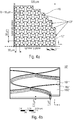
- Fig. 3a is a top view of a fourth of a membrane, i.e. a roughly 90° segment of a circle portion (cf. symmetry lines).
- the membrane is provided with the reference numeral 12' and comprises an auxetic structure 16'.
- the suspension or fixed support of the membrane 12' is provided with the reference numeral 12f' using the arrows.
- the auxetic structure 16' is illustrated in a three-dimensional view in Fig. 3b and in an enlarged view in Fig. 3c .
- the membrane 12' comprises a membrane plane along which it exemplarily extends at a thickness of 0.5 ⁇ m (generally in a range between 0.1 ⁇ m and 1.0 ⁇ m or 0.01 ⁇ m and 10 ⁇ m).
- the auxetic structure 16' projects from the membrane plane of the membrane 12' as a type of profile or arch. This profile is illustrated in an enlarged manner in Fig. 3c and provided with the reference numeral 16p'. As can be recognized, this profile 16p' is introduced into the membrane 12' such that the membrane thickness of 0.5 ⁇ m remains roughly constant across the arch.
- a step which is provided with the reference numeral 16s' is formed here.
- the height of the step is roughly 1 ⁇ m, but may vary in the range between 0.1 or 0.5 and 5.0 or 10 or 20 ⁇ m, depending on the embodiment.
- the profile 16p' extends in curved lines (S-shaped curves) over the entire area so that an auxetic area element 16f' is enclosed by four curved (90° bends) boundary lines 16fcx' and 16fc' each.
- the entire auxetic structure 16' is formed by a plurality of such area elements 16f' or auxetic structural elements arranged in several rows, as is illustrated in Fig. 3a .
- the rows and the structural elements in a row are always arranged to be directly adjacent to one another so that two area elements 16f1' and 16f2' are separated from each other by a profile 16p' therebetween.
- the area element 16f2' is rotated by 90° relative to the area element 16f1' so that the convex side 16fcx' of 16f2' forms the concave side 16fc' of 16f1'.
- the same mechanism for defining the boundary between the area elements 16f' extends in both lateral dimensions of the membrane 12'.
- the radii of all the profile lines 16p' may, for example, be approximately 20 ⁇ m (in this case 18 ⁇ m or, generally, in a range between 5 ⁇ m and 40 ⁇ m or between 2 ⁇ m and 100 ⁇ m).
- each auxetic element 16f may also be defined by edge-to-edge dimensions (the corner points where the respective concave boundary line contacts the adjacent convex one).
- the dimensions are 30x30 ⁇ m, wherein, depending on the design of the auxetic structure 16', these dimensions may, of course, also be varied as desired, like in a range between 5 ⁇ m and 500 ⁇ m. It is to be pointed out here that, depending on the orientation of the auxetic structural element 16f', the 30 ⁇ m may either represent the width or the height.
- Figs. 4a and 4b illustrate another auxetic structure.
- Fig. 4a shows a 90° section of a membrane 12" (a quarter of a membrane) having an auxetic structure 16".
- the membrane 12" is cantilevered fixedly at the points characterized by 12f".
- Fig. 4b is a detailed three-dimensional illustration of the auxetic structure 16".
- the auxetic structure 16" comprises a plurality of auxetic area elements 16f". Exemplarily, two auxetic area elements 16f1" and 16f2" are illustrated here.
- the auxetic area element 16f1" is located in a different plane (in parallel to the entire membrane) than the area element 16f2" (also in parallel to the entire membrane).
- a step 16s" forms between the two auxetic area elements 16f1" and 16f2.
- This step 16s" forms the boundary of the auxetic areas 16f1" and 16f2" and, as has already been mentioned before, is arranged such that each auxetic area element 16f" is enclosed by two concave and two convex boundary lines (lateral boundary lines).
- the step 16s" is formed by the structure of the membrane 12" which exemplarily again has a thickness of 0.5 ⁇ m (generally in a range between 0.01 ⁇ m and 5.0 ⁇ m), wherein the corrugation height (step height) is 1 ⁇ m each (generally in a range between 0.5 ⁇ m and 10 ⁇ m).
- an auxetic area element 16f1''' in a lower plane will always alternate with an auxetic area element 16f2" in a higher plane.
- the auxetic area elements it would, of course, also be conceivable for the auxetic area elements to be provided in more than two planes. Generally, the different planes form the surface for the membrane 12".
- the intrinsic stress again is 20, 40 MPa.
- the intrinsic stress is indicated with no deformation or before deformation.
- the intrinsic stress is distributed very equally over the steps, when there is no external deformation (0 Pa).
- the same With a deformation (10 Pa), the same extends in a radial-symmetrical manner from the center of symmetry (cf. zero point in the 1 ⁇ 4 membrane models of Figs. 3a and 4a ) to the edge.
- the stress is distributed homogenously across the membrane, decreasing towards the radius.
- a compliance in a range of 9.81 nm/Pa was calculated/simulated in the auxetic structure of Fig. 3a with an externally applied stress of 20 MPa, whereas, in the auxetic structure of Fig. 4a , a compliance of 6.98 nm/Pa was obtained.
- the compliance of a simple membrane is 2.5 nm/Pa
- the auxetic structures are applied on membranes, like silicon membranes for SiMic.
- these membranes are represented to be round.
- the membrane may also comprise a different shape, like an oval or quadrangular shape, for example.
- the lateral boundaries of the auxetic area elements are formed by 90° segments of a circle (formed by a profile 16s' or step 16s") so that several 90° segments arranged one behind the other and to be curved alternatingly in opposite directions extend laterally along a direction and a type of grid is formed in combination with the several boundary lines.
- the angles of the segments of a circle or the orientation of the boundary lines set up by the segments of a circle may also vary (45° angle or, generally, in a range between 15 and 120°, for example).
- auxetic structures in combination with the membrane is not restricted to the auxetic structures as illustrated, but that further auxetic structures are also conceivable.
- two boundary lines next to each other meandering along one direction are preferably implemented to be symmetrical among each other, with an interposed axis of symmetry along the direction of propagation.
- auxetic structure extends over the entire membrane area.
- auxetic structure it would also be feasible for the auxetic structure to be located only in portions on the membrane.
- Another embodiment relates to a manufacturing method of a membrane comprising an auxetic structure.
- the membrane is manufactured by means of typical semiconductor manufacturing methods, like by providing a sacrificial layer and applying the membrane onto the sacrificial layer before removing the sacrificial layer for exposing the membrane.
- a sacrificial layer is structured, for example in order to implement the trenches or positive profiles in the membrane. The structuring may also be done such that the auxetic structural areas arranged in different planes are formed with the respective steps therebetween.
- a preferred field of application of membranes comprising auxetic structures is manufacturing MEMS microphones or silicon microphones, like in smart phones, for example.
- a membrane comprising an auxetic structure it is of advantage for a membrane comprising an auxetic structure to exhibit a higher sensitivity than a different (silicon) membrane of comparable size or comparable thickness. This means that the combination of an auxetic structure with a silicon membrane can achieve signal amplification for microphones, with, at the same time, higher mechanical stability.
- auxetic structural elements have been discussed as elements having an identical or similar function, the elements may be also different within a membrane.
- shape and orientation of each (at least two) auxetic structural elements could be rotational symmetric and/or the size can be scaled with respect to the position inside the membrane.
Landscapes
- Physics & Mathematics (AREA)
- Engineering & Computer Science (AREA)
- Acoustics & Sound (AREA)
- Signal Processing (AREA)
- Micromachines (AREA)
Abstract
An MEMS device comprises a membrane configured to oscillate and comprising an auxetic structure at least in portions thereof.
Description
- Embodiments of the present disclosure relate to an MEMS device, to a sound transducer comprising said MEMS device, and to a manufacturing method of said MEMS device.
- MEMS (microelectromechanical system) devices allow realizing sound transducers, like loudspeakers or microphones, for example. Such sound transducers typically comprise a membrane which can be excited to oscillate externally or by means of sound in the surroundings (microphone), or be excited to oscillate electrically (for realizing a loudspeaker). These membranes are formed by means of semiconductor technologies in or on a substrate. Apart from the "MEMS microphone" and "MEMS sound transducer" applications, there are further MEMS devices, like MEMS-based sensors, for example pressure sensors or concentration sensors having a functional layer.
- In particular in microphones, an important parameter is the sensitivity of the entire system. Typically, the sensitivity of the microphone can be improved by reducing the membrane thickness or by increasing the membrane area (diameter). Both ways have disadvantages. Increasing the size of a membrane is expensive and with reduction of the membrane thickness the microphones lose mechanical stability, in particular during manufacturing and in the application.
- Embodiments of the present disclosure provide an MEMS device comprising a membrane configured to oscillate (when excited externally or excited electrically). The membrane comprises an auxetic structure at least in portions thereof. In accordance with embodiments, an auxetic structure is a structure which, as a consequence of expansion, e.g. expansion of the membrane in a first (lateral) direction, expands of its own accord in a second, e.g. orthogonal (lateral) direction, and/or wherein the thickness of the membrane increases as a consequence of the expansion in the first direction. When reversing this process, auxetic structures also exhibit comparable characteristics, which means that, when compressing the membrane in the first (lateral) direction, the membrane will be compressed of its own accord or due to the auxetic structure in the second, e.g. orthogonal, (lateral) direction, or the thickness will be changed (reduced) correspondingly. In accordance with an alternative definition, we speak of an auxetic structure when the structure or the material has a negative Poisson's ratio. Starting here, the material or structure considered exemplarily becomes thicker in a direction perpendicular to the force applied.
- In accordance with embodiments, the auxetic structure comprises a plurality of auxetic structural elements, like identical or mutually similar structural elements. Each of these auxetic structural elements may be formed by an area (in parallel to the membrane) enclosed or defined by four, preferably arched, lateral boundaries (like profile structures, steps or trenches). In accordance with embodiments, these (preferably identical) structural elements are arranged in one or several rows (row after row in order to cover the membrane region at least in an area portion). The plurality of the auxetic structural elements in one row are mutually adjacent so that a first and a third one exhibit an identical orientation, wherein a second auxetic structural element arranged therebetween is rotated compared to the first and third auxetic structural elements, like rotated by 90°. According to further embodiments, the individual auxetic structural elements can be different within a membrane. I.e. the auxetic structure comprises a plurality of auxetic structural elements, wherein at least two auxetic structural elements differ from each other.
- Assuming that, in accordance with embodiments, each auxetic structural element is formed by two opposite lateral boundaries (i.e. along the membrane plane) and two further opposite lateral boundaries, it becomes obvious that each auxetic structural element forms a kind of quadrangle, for example, wherein, in accordance with embodiments, the lateral opposite boundaries and the further lateral opposite boundaries are bent (the result not being a classical quadrangle). In accordance with embodiments, the arched opposite lateral boundaries may be formed as follows: each auxetic structural element is confined by two opposite lateral concave and two opposite lateral convex boundaries so that the auxetic area element of the respective auxetic structural element is enclosed by the two concave and the two convex boundaries. In this embodiment, it is obvious that, when assuming the lateral structural elements to be arranged in a row, wherein the lateral structural element arranged between two other lateral structural elements is rotated when compared to the other ones, the concave boundary for the central (rotated) lateral structural element also represents the convex boundary for the adjacent (non-rotated) structural element. According to further embodiments, the auxetic structural elements can be also different within a membrane. For example, the orientation could be rotational symmetric and/or the size can be scaled with respect to the position inside the membrane.
- In accordance with embodiments, each lateral boundary is formed by a raised profile, like a dome from the substrate plane, or by a trench profile. Here, the raised profile or the trench profile divides the plurality of auxetic structural elements among one another. It is also to be mentioned at this point that, in accordance with embodiments, the membrane thickness only varies minimally across the profile, i.e. only at the transitions, wherein, in the region where the profile is formed, the membrane thickness may exemplarily exhibit the same thickness as the membrane thickness in the region of the area element (subsequently referred to as auxetic area element, which is enclosed by the lateral boundaries) of the auxetic structural element. In accordance with embodiments, the plurality of the auxetic structural elements each comprise an auxetic area element, wherein the auxetic area elements extend in parallel to or along the membrane plane. In accordance with embodiments, two of the auxetic area elements are arranged in two different planes.
- Assuming that each auxetic structural element comprises an auxetic area element enclosed by the (four) boundaries, in accordance with further embodiments, it would be feasible for the auxetic area elements to be positioned alternatingly in a top and a bottom plane. In accordance with embodiments, the lateral boundary here is formed by a step forming a transition from one auxetic area element of one of the plurality of auxetic structural elements relative to another auxetic area element of an adjacent one of the plurality of auxetic structural elements.
- Both in an embodiment where the lateral boundary is formed by a step, and in the embodiment where the lateral boundary is formed by a profile or a trench profile, it is to be mentioned that, in accordance with embodiments, the step or profile/trench is formed by the membrane itself.
- Another embodiment relates to a sound transducer comprising an MEMS device as defined above. In accordance with further embodiments, the sound transducer may form a microphone configured to be excited to oscillate when excited by sound from the surroundings and to output an electrical signal which depends on the sound.
- Further embodiments provide a manufacturing method for forming an MEMS device as discussed above, wherein the method comprises the step of forming a membrane by means of depositing, wherein depositing takes place such that the auxetic structure is formed in the membrane.
- Further developments are defined in the sub-claims. Embodiments of the present disclosure will be discussed referring to the appended drawings, in which:
- Fig. 1
- shows a schematic illustration of an MEMS device in accordance with a basic embodiment;
- Figs. 2a-h
- show schematic illustrations for illustrating the principle of auxetic structures;
- Figs. 3a-c
- show a schematic illustration of a membrane having an auxetic structure in accordance with an embodiment;
- Figs. 4a-b
- show schematic illustrations of a membrane having an auxetic structure in accordance with another embodiment;
- Figs. 5a-b
- show schematic illustrations of simulation results for membranes having auxetic structures in accordance with embodiments.
- Before discussing embodiments of the present disclosure below referring to the appended drawings, it is to be pointed out that equal effects and structures are provided with equal reference numerals so that the description thereof is mutually applicable or exchangeable.
-
Fig. 1 shows anMEMS device 10, like a sound transducer in the form of a loudspeaker or a microphone, for example. ThisMEMS device 10 comprises amembrane 12 which is exemplarily formed in thesubstrate 14 of theMEMS device 10. Themembrane 12 comprises anauxetic structure 16. This auxetic structure may, for example, be applied onto themembrane 12, or themembrane 12 may be formed such that the auxetic structure is formed in the membrane, wherein the latter will be assumed for the following discussion. - As is illustrated here, the
auxetic structure 16 is implemented by themembrane 12 being structured. Thestructuring 16p is, for example, formed by impressing aprofile 16p into themembrane 12. In accordance with embodiments, the structuring is performed such that the membrane comprises a plurality of profiles extending laterally in two (crossing) directions, like a grid, along the membrane. In other words, this means that theprofiles 16p on the membrane surface impress elevations or recesses in a type of grid shape. Anauxetic area element 16f each which is enclosed by theprofile 16p on four sides is formed in the meshes of the "grid", thereby forming four corners at the points of contact of theprofiles 16p. This means that theprofiles 16p border theauxetic area elements 16f laterally (lateral boundaries along themembrane 12 or along the respective plane). As is illustrated here, theprofiles 16p/boundary lines are preferably (but not necessarily) curved. - Generally speaking, the
membrane 12 having theauxetic structure 16 allows an extension of themembrane 12 in a first direction (cf. direction x), resulting in the membrane to also expand in a second direction (like, for example, direction y, orthogonal to direction x). Alternatively or additionally, it would also be conceivable for themembrane 12 to vary, like increase, in its thickness (cf. z direction) as a consequence of an expansion in the x direction. In accordance with embodiments, this characteristic which is provided by theauxetic structure 16 results in themembrane 12 being more flexible. This is due to the fact that, by applying theauxetic structure 16 on the surface of themembrane 12, for example, or by structuring themembrane 12 in the form of an auxetic structure, the membrane generally, or in portions, exhibits higher a flexibility. In case theMEMS device 10 is, for example, used as a microphone, higher a sensitivity of themicrophone 10 is achieved by the increase in flexibility of themembrane 12. When sticking to the example of a microphone, another positive side effect is that themembrane 12 is considerably more robust to mechanical overstress, like in the case of dropping it. - Subsequently, the principle of auxetic structures will be discussed below referring to
Figs. 2a-h . -
Fig. 2a shows anauxetic structure 16 comprisingboundaries 16g bordering theauxetic area element 16f and extending laterally on the plane. - The action mechanism of such an auxetic structure will be discussed referring to
Fig. 2b . Reference here is made to the auxetic structural element provided with thereference numeral 16f*. - The auxetic
structural element 16f* comprises two concave lateral boundaries 16fc* and two convex boundaries 16fcx*. The deformation, which is illustrated by the arrows, exemplarily acts on the concave boundaries 16fcx*, resulting in the same to be compressed, as is illustrated in broken lines. Consequently, the concave boundaries are also compressed towards the interior by the points of contact of the concave and convex boundaries 16fcx* and 16fc*, as is illustrated in broken lines. When considering the entireauxetic structure 16, this means that, when compressing in one direction (like y direction), a compression in the x direction will also result, as is illustrated inFig. 2c . - In
Fig. 2c , the broken line illustrates the original shape with no external force applied, wherein the area having the continuous line illustrates compression of theauxetic structure 16f*. For comparative purposes, reference is made toFig. 2d where the identical area is compressed in the y direction, however with no auxetic structure, the result of this, however, being an expansion in the x direction. It is to be pointed out here that, with auxetic structures, the same principle also applies in the case of an expansion, i.e. in the case of a tensile force in the y direction, the result being an expansion of the area in the x direction. The deformations within the auxetic structure are illustrated inFig. 2g for the broken-line area ofFig. 2c in the compressed state. Expressed generally, auxetic structures also exhibit a negative Poisson's ratio:
-
Fig. 2g illustrates anauxetic structure 16 which is, for example, employed in the illustrative example ofFig. 2c . Thisauxetic structure 16 is basically implemented to be two-dimensional. However, there are also three-dimensional auxetic structures, as is, for example, illustrated inFig. 2h . - Depending on the application, the membrane discussed referring to
Fig. 1 may comprise either two- or three-dimensional auxetic structures. - An example of an auxetic structure for a membrane each will be discussed below referring to
Figs. 3 and4 . -
Fig. 3a is a top view of a fourth of a membrane, i.e. a roughly 90° segment of a circle portion (cf. symmetry lines). The membrane is provided with the reference numeral 12' and comprises an auxetic structure 16'. The suspension or fixed support of the membrane 12' is provided with thereference numeral 12f' using the arrows. - The auxetic structure 16' is illustrated in a three-dimensional view in
Fig. 3b and in an enlarged view inFig. 3c . As can be recognized, the membrane 12' comprises a membrane plane along which it exemplarily extends at a thickness of 0.5 µm (generally in a range between 0.1 µm and 1.0 µm or 0.01 µm and 10 µm). The auxetic structure 16' projects from the membrane plane of the membrane 12' as a type of profile or arch. This profile is illustrated in an enlarged manner inFig. 3c and provided with the reference numeral 16p'. As can be recognized, thisprofile 16p' is introduced into the membrane 12' such that the membrane thickness of 0.5 µm remains roughly constant across the arch. Only in the region of the transition from the membrane area element (cf. reference numeral 16f') to the raisedregion 16p', the thickness is not constant. A step which is provided with the reference numeral 16s' is formed here. The height of the step is roughly 1 µm, but may vary in the range between 0.1 or 0.5 and 5.0 or 10 or 20 µm, depending on the embodiment. Generally, thestep 16s' has a height of n times the thickness of the membrane, wherein n may vary in a range between 0.5 and 20 (in this case n = 2). - The
profile 16p' extends in curved lines (S-shaped curves) over the entire area so that anauxetic area element 16f' is enclosed by four curved (90° bends) boundary lines 16fcx' and 16fc' each. The entire auxetic structure 16' is formed by a plurality ofsuch area elements 16f' or auxetic structural elements arranged in several rows, as is illustrated inFig. 3a . The rows and the structural elements in a row are always arranged to be directly adjacent to one another so that two area elements 16f1' and 16f2' are separated from each other by aprofile 16p' therebetween. The area element 16f2' is rotated by 90° relative to the area element 16f1' so that the convex side 16fcx' of 16f2' forms the concave side 16fc' of 16f1'. The same mechanism for defining the boundary between thearea elements 16f' extends in both lateral dimensions of the membrane 12'. The radii of all theprofile lines 16p' may, for example, be approximately 20 µm (in this case 18 µm or, generally, in a range between 5 µm and 40 µm or between 2 µm and 100 µm). This is dependent on how big the auxetic structure 16' is, which in this case extends over the entire membrane surface of themembrane 12, having a radius in the rage from 300 µm up to 1000 µm. The intrinsic stress here is 20, 40 MPa, for example. Apart from the absolute dimensions, eachauxetic element 16f may also be defined by edge-to-edge dimensions (the corner points where the respective concave boundary line contacts the adjacent convex one). In this embodiment, the dimensions are 30x30 µm, wherein, depending on the design of the auxetic structure 16', these dimensions may, of course, also be varied as desired, like in a range between 5 µm and 500 µm. It is to be pointed out here that, depending on the orientation of the auxeticstructural element 16f', the 30 µm may either represent the width or the height. -
Figs. 4a and 4b illustrate another auxetic structure. In a top view,Fig. 4a shows a 90° section of amembrane 12" (a quarter of a membrane) having anauxetic structure 16". Themembrane 12" is cantilevered fixedly at the points characterized by 12f".Fig. 4b is a detailed three-dimensional illustration of theauxetic structure 16". - The
auxetic structure 16" comprises a plurality ofauxetic area elements 16f". Exemplarily, two auxetic area elements 16f1" and 16f2" are illustrated here. The auxetic area element 16f1" is located in a different plane (in parallel to the entire membrane) than the area element 16f2" (also in parallel to the entire membrane). Thus, astep 16s" forms between the two auxetic area elements 16f1" and 16f2". Thisstep 16s" forms the boundary of the auxetic areas 16f1" and 16f2" and, as has already been mentioned before, is arranged such that eachauxetic area element 16f" is enclosed by two concave and two convex boundary lines (lateral boundary lines). - Like in the embodiment having a profile, the
step 16s" here is formed by the structure of themembrane 12" which exemplarily again has a thickness of 0.5 µm (generally in a range between 0.01 µm and 5.0 µm), wherein the corrugation height (step height) is 1 µm each (generally in a range between 0.5 µm and 10 µm). - In accordance with embodiments, in the structure as discussed before, an auxetic area element 16f1''' in a lower plane will always alternate with an auxetic area element 16f2" in a higher plane. In accordance with further embodiments, it would, of course, also be conceivable for the auxetic area elements to be provided in more than two planes. Generally, the different planes form the surface for the
membrane 12". - For the sake of completeness, it is to be mentioned here that the intrinsic stress (tensile) again is 20, 40 MPa. In
Fig. 5a , the intrinsic stress is indicated with no deformation or before deformation. As can be recognized from the hatchings, the intrinsic stress is distributed very equally over the steps, when there is no external deformation (0 Pa). With a deformation (10 Pa), the same extends in a radial-symmetrical manner from the center of symmetry (cf. zero point in the ¼ membrane models ofFigs. 3a and4a ) to the edge. As can be recognized from the hatchings, the stress is distributed homogenously across the membrane, decreasing towards the radius. - It is to be pointed out here that a compliance in a range of 9.81 nm/Pa was calculated/simulated in the auxetic structure of
Fig. 3a with an externally applied stress of 20 MPa, whereas, in the auxetic structure ofFig. 4a , a compliance of 6.98 nm/Pa was obtained. For comparison, the compliance of a simple membrane is 2.5 nm/Pa
In the above embodiments, it has been assumed that the auxetic structures are applied on membranes, like silicon membranes for SiMic. In accordance with the embodiments ofFigs. 3a and 3b , these membranes are represented to be round. In accordance with further embodiments, the membrane may also comprise a different shape, like an oval or quadrangular shape, for example. - In the above embodiments, it has been assumed that the lateral boundaries of the auxetic area elements (cf.
reference numbers 16f', 16f1', 16f2' and 16f", 16f1", 16f2") are formed by 90° segments of a circle (formed by aprofile 16s' or step 16s") so that several 90° segments arranged one behind the other and to be curved alternatingly in opposite directions extend laterally along a direction and a type of grid is formed in combination with the several boundary lines. In accordance with further embodiments, the angles of the segments of a circle or the orientation of the boundary lines set up by the segments of a circle may also vary (45° angle or, generally, in a range between 15 and 120°, for example). Expressed differently, this means that using the auxetic structures in combination with the membrane is not restricted to the auxetic structures as illustrated, but that further auxetic structures are also conceivable. With regard to the boundaries, it is to be mentioned that two boundary lines next to each other meandering along one direction are preferably implemented to be symmetrical among each other, with an interposed axis of symmetry along the direction of propagation. - In the above embodiments, it has also been assumed that the auxetic structure extends over the entire membrane area. However, it is to be pointed out here that, in accordance with further embodiments, it would also be feasible for the auxetic structure to be located only in portions on the membrane.
- In the above embodiments, it has always been assumed that the boundaries are formed by steps or raised profiles, wherein it is to be mentioned here that a deformation by a trench or a combination of profile and trench would, of course, also be conceivable.
- Another embodiment relates to a manufacturing method of a membrane comprising an auxetic structure. The membrane is manufactured by means of typical semiconductor manufacturing methods, like by providing a sacrificial layer and applying the membrane onto the sacrificial layer before removing the sacrificial layer for exposing the membrane. In accordance with embodiments, before applying the membrane, a sacrificial layer is structured, for example in order to implement the trenches or positive profiles in the membrane. The structuring may also be done such that the auxetic structural areas arranged in different planes are formed with the respective steps therebetween.
- As has already been mentioned in the above embodiments, a preferred field of application of membranes comprising auxetic structures is manufacturing MEMS microphones or silicon microphones, like in smart phones, for example. In particular in such cases of application, it is of advantage for a membrane comprising an auxetic structure to exhibit a higher sensitivity than a different (silicon) membrane of comparable size or comparable thickness. This means that the combination of an auxetic structure with a silicon membrane can achieve signal amplification for microphones, with, at the same time, higher mechanical stability.
- Although in above embodiments, the auxetic structural elements have been discussed as elements having an identical or similar function, the elements may be also different within a membrane. For example, the shape and orientation of each (at least two) auxetic structural elements could be rotational symmetric and/or the size can be scaled with respect to the position inside the membrane.
- The embodiments described above merely represent an illustration of principles of the present disclosure. Modifications and variations of the arrangements described herein and details will be obvious for others skilled in the art. Therefore, the disclosure is intended to be restricted solely by the scope of the following claims, but not by the specific details having been presented herein using the description and discussion of embodiments.
Claims (15)
- An MEMS device (10) comprising:a membrane (12, 12', 12") configured to oscillate and comprising an auxetic structure (16, 16', 16") at least in portions thereof.
- The MEMS device (10) according to claim 1, wherein the membrane (12, 12', 12") is configured to expand, when oscillating, in at least a first lateral direction,
wherein the auxetic structure (16, 16', 16") is configured to expand the membrane (12, 12', 12") in a second direction as a consequence of the expansion of the membrane (12, 12', 12") in the first direction, and/or wherein the auxetic structure (16, 16', 16") is configured to increase a thickness of the membrane (12, 12', 12") as a consequence of the expansion in the first direction. - The MEMS device (10) in accordance with any of the preceding claims, wherein the auxetic structure (16, 16', 16") is formed by a plurality of auxetic structural elements (16f*, 16f', 16f").
- The MEMS device (10) in accordance with claim 3, wherein each auxetic structural element (16f*, 16f', 16f") is identical.
- The MEMS device (10) in accordance with claim 3 or 4, wherein at least three of the plurality of auxetic structural elements (16f*, 16f', 16f") are arranged in a row to be mutually adjacent so that a first and a third of the auxetic structural elements (16f*, 16f', 16f", 16f1') exhibit an identical orientation, wherein a second auxetic structural element (16f*, 16f', 16f") arranged between the first and third auxetic structural elements (16f2') is rotated compared to the first and second auxetic structural elements (16f*, 16f', 16f", 16f2').
- The MEMS device (10) in accordance with any of claims 3 to 5, wherein each auxetic structural element (16f*, 16f', 16f") is enclosed by two opposite lateral and two further opposite lateral boundaries (16fcx*, 16fc, 16fc', 16fcx').
- The MEMS device (10) in accordance with any of claims 3 to 5, wherein each auxetic structural element (16f*, 16f', 16f") is enclosed by two opposite lateral concave and two opposite lateral convex boundaries.
- The MEMS device (10) in accordance with claim 6 or 7, wherein each lateral boundary (16fcx*, 16fc, 16fc', 16fcx') is formed by a raised profile (16p') or a trench profile which borders one of the plurality of auxetic structural elements (16f*, 16f', 16f") from an adjacent one of the plurality of auxetic structural elements (16f*, 16f', 16f").
- The MEMS device (10) in accordance with any of claims 6, 7 or 8, wherein the membrane (12, 12', 12") forms the raised profile (16p') or the trench profile.
- The MEMS device (10) in accordance with any of claims 3 to 7, wherein the plurality of auxetic structural elements (16f*, 16f', 16f") each comprise auxetic area elements (16f', 16f") extending along the membrane plane, and wherein the auxetic area elements (16f', 16f") of the plurality of auxetic structural elements (16f*, 16f', 16f") are arranged in at least two different planes.
- The MEMS device (10) in accordance with any of claims 6, 7 or 10, wherein each lateral boundary (16fcx*, 16fc, 16fc', 16fcx') is formed by a step (16s") forming a transition from one auxetic area element (16f', 16f") of one of the plurality of auxetic structural elements (16f*, 16f', 16f") to an auxetic area element (16f', 16f") of an adjacent one of the plurality of auxetic structural elements (16f*, 16f', 16f").
- The MEMS device (10) in accordance with claim 11, wherein the step (16s") is formed by the membrane (12, 12', 12").
- A sound transducer comprising an MEMS device (10) in accordance with any of the preceding claims.
- The sound transducer in accordance with claim 13, the sound transducer forming a microphone configured to output, when excited to oscillate by sound from the surroundings, an electrical signal which is dependent on the sound.
- A method for manufacturing an MEMS device (10) in accordance with any of claims 1 to 12, the method comprising the step of:forming a membrane (12, 12', 12") by means of depositing, depositing taking place such that the auxetic structure (16, 16', 16") is formed in the membrane (12, 12', 12").
Priority Applications (1)
| Application Number | Priority Date | Filing Date | Title |
|---|---|---|---|
| EP18183013.4A EP3595333A1 (en) | 2018-07-11 | 2018-07-11 | Mems device |
Applications Claiming Priority (1)
| Application Number | Priority Date | Filing Date | Title |
|---|---|---|---|
| EP18183013.4A EP3595333A1 (en) | 2018-07-11 | 2018-07-11 | Mems device |
Publications (1)
| Publication Number | Publication Date |
|---|---|
| EP3595333A1 true EP3595333A1 (en) | 2020-01-15 |
Family
ID=63165138
Family Applications (1)
| Application Number | Title | Priority Date | Filing Date |
|---|---|---|---|
| EP18183013.4A Withdrawn EP3595333A1 (en) | 2018-07-11 | 2018-07-11 | Mems device |
Country Status (1)
| Country | Link |
|---|---|
| EP (1) | EP3595333A1 (en) |
Cited By (3)
| Publication number | Priority date | Publication date | Assignee | Title |
|---|---|---|---|---|
| CN115427172A (en) * | 2020-04-15 | 2022-12-02 | 西门子能源全球有限两合公司 | Auxetic 3D Structures for Additive Manufacturing Applications |
| CN115842990A (en) * | 2023-02-15 | 2023-03-24 | 共达电声股份有限公司 | Vibrating diaphragm system and loudspeaker |
| EP4696605A1 (en) | 2024-08-16 | 2026-02-18 | Airbus Defence and Space GmbH | Air inlet arrangement for a low observable aircraft and same |
Citations (1)
| Publication number | Priority date | Publication date | Assignee | Title |
|---|---|---|---|---|
| WO2016112366A1 (en) * | 2015-01-09 | 2016-07-14 | President And Fellows Of Harvard College | Negative poisson's ratio waffle structures |
-
2018
- 2018-07-11 EP EP18183013.4A patent/EP3595333A1/en not_active Withdrawn
Patent Citations (1)
| Publication number | Priority date | Publication date | Assignee | Title |
|---|---|---|---|---|
| WO2016112366A1 (en) * | 2015-01-09 | 2016-07-14 | President And Fellows Of Harvard College | Negative poisson's ratio waffle structures |
Non-Patent Citations (5)
| Title |
|---|
| BRUGGI M ET AL: "Optimization of auxetic structures for MEMS applications", 2016 17TH INTERNATIONAL CONFERENCE ON THERMAL, MECHANICAL AND MULTI-PHYSICS SIMULATION AND EXPERIMENTS IN MICROELECTRONICS AND MICROSYSTEMS (EUROSIME), IEEE, 18 April 2016 (2016-04-18), pages 1 - 5, XP032897813, DOI: 10.1109/EUROSIME.2016.7463381 * |
| CAROLIN K?RNER ET AL: "A systematic approach to identify cellular auxetic materials", SMART MATERIALS AND STRUCTURES, IOP PUBLISHING LTD., BRISTOL, GB, vol. 24, no. 2, 18 December 2014 (2014-12-18), pages 25013, XP020278181, ISSN: 0964-1726, [retrieved on 20141218], DOI: 10.1088/0964-1726/24/2/025013 * |
| GASPAR N ET AL: "A generalised three-dimensional tethered-nodule model for auxetic materials", JOURNAL OF MATERIALS SCIENCE, KLUWER ACADEMIC PUBLISHERS, BO, vol. 46, no. 2, 31 August 2010 (2010-08-31), pages 372 - 384, XP019854904, ISSN: 1573-4803, DOI: 10.1007/S10853-010-4846-0 * |
| LEVY O ET AL: "Design considerations for negative Poisson ratio structures under large deflection for MEMS applications", SMART MATERIALS AND STRUCTURES, IOP PUBLISHING LTD., BRISTOL, GB, vol. 15, no. 5, 1 October 2006 (2006-10-01), pages 1459 - 1466, XP020105494, ISSN: 0964-1726, DOI: 10.1088/0964-1726/15/5/035 * |
| ULRIK DARLING LARSEN ET AL: "Design and Fabrication of Compliant Micromechanisms and Structures with Negative Poisson's Ratio", JOURNAL OF MICROELECTROMECHANICAL SYSTEMS, IEEE SERVICE CENTER, US, vol. 6, no. 2, 1 June 1997 (1997-06-01), XP011034744, ISSN: 1057-7157 * |
Cited By (6)
| Publication number | Priority date | Publication date | Assignee | Title |
|---|---|---|---|---|
| CN115427172A (en) * | 2020-04-15 | 2022-12-02 | 西门子能源全球有限两合公司 | Auxetic 3D Structures for Additive Manufacturing Applications |
| US12228046B2 (en) | 2020-04-15 | 2025-02-18 | Siemens Energy Global GmbH & Co. KG | Auxetic three-dimensional structure utilized in additive manufacturing applications |
| CN115842990A (en) * | 2023-02-15 | 2023-03-24 | 共达电声股份有限公司 | Vibrating diaphragm system and loudspeaker |
| CN115842990B (en) * | 2023-02-15 | 2023-05-16 | 共达电声股份有限公司 | Vibrating diaphragm system and loudspeaker |
| EP4696605A1 (en) | 2024-08-16 | 2026-02-18 | Airbus Defence and Space GmbH | Air inlet arrangement for a low observable aircraft and same |
| DE102024123401A1 (en) * | 2024-08-16 | 2026-02-19 | Airbus Defence and Space GmbH | AIR INTAKE ARRANGEMENT FOR A RDONG-DETECTABLE AIRCRAFT AND THE SAME |
Similar Documents
| Publication | Publication Date | Title |
|---|---|---|
| KR102816960B1 (en) | MEMS transducers with improved performance | |
| EP2535310B1 (en) | Mems devices having membrane and methods of fabrication thereof | |
| CN102811413B (en) | Plate, transducer and for the manufacture of the method with operate both transducers | |
| US10661308B2 (en) | High displacement ultrasonic transducer | |
| CN103121657B (en) | MEMS and manufacture method thereof | |
| JP6051310B2 (en) | A method for optimizing the placement of piezoelectric actuators in micro-variable lens bodies | |
| JP5436013B2 (en) | Mechanical electrical change element | |
| CN111294715B (en) | Piezoelectric MEMS microphone | |
| US20170325030A1 (en) | Micromechanical piezoelectric actuators for implementing large forces and deflections | |
| TW200926864A (en) | Sensing membrane and micro-electro-mechanical system device using the same | |
| EP3314911B1 (en) | Dsr speaker elements and methods of manufacturing thereof | |
| CN110024284B (en) | Angularly coupled resonator array | |
| US20180007473A1 (en) | Mems device and process | |
| CN114697841A (en) | MEMS microphone and vibrating diaphragm structure thereof | |
| US20110254405A1 (en) | Electromechanical transducer and production method therefor | |
| CN112584283A (en) | Piezoelectric MEMS microphone, array thereof and preparation method thereof | |
| CN209659620U (en) | Piezoelectric type MEMS microphone | |
| TW200927634A (en) | MEMS device and process | |
| JP2009033698A (en) | Diaphragm structure and acoustic sensor | |
| CN113727265A (en) | Capacitive MEMS microphone structure and manufacturing method thereof | |
| CN214315603U (en) | Piezoelectric MEMS Microphone and Its Array | |
| KR101893486B1 (en) | Rigid Backplate Structure Microphone and Method of Manufacturing the Same | |
| CN108235217B (en) | Method for preparing microphone | |
| CN119729321B (en) | MEMS element and electroacoustic conversion device | |
| EP4586645A1 (en) | Mems device |
Legal Events
| Date | Code | Title | Description |
|---|---|---|---|
| PUAI | Public reference made under article 153(3) epc to a published international application that has entered the european phase |
Free format text: ORIGINAL CODE: 0009012 |
|
| AK | Designated contracting states |
Kind code of ref document: A1 Designated state(s): AL AT BE BG CH CY CZ DE DK EE ES FI FR GB GR HR HU IE IS IT LI LT LU LV MC MK MT NL NO PL PT RO RS SE SI SK SM TR |
|
| AX | Request for extension of the european patent |
Extension state: BA ME |
|
| STAA | Information on the status of an ep patent application or granted ep patent |
Free format text: STATUS: THE APPLICATION IS DEEMED TO BE WITHDRAWN |
|
| 18D | Application deemed to be withdrawn |
Effective date: 20200716 |