EP3595263B1 - Systeme und verfahren für entitätsnetzwerkanalytik - Google Patents
Systeme und verfahren für entitätsnetzwerkanalytik Download PDFInfo
- Publication number
- EP3595263B1 EP3595263B1 EP19185698.8A EP19185698A EP3595263B1 EP 3595263 B1 EP3595263 B1 EP 3595263B1 EP 19185698 A EP19185698 A EP 19185698A EP 3595263 B1 EP3595263 B1 EP 3595263B1
- Authority
- EP
- European Patent Office
- Prior art keywords
- entity
- connections
- records
- entity representation
- determining
- Prior art date
- Legal status (The legal status is an assumption and is not a legal conclusion. Google has not performed a legal analysis and makes no representation as to the accuracy of the status listed.)
- Active
Links
Images






Classifications
-
- G—PHYSICS
- G06—COMPUTING OR CALCULATING; COUNTING
- G06F—ELECTRIC DIGITAL DATA PROCESSING
- G06F16/00—Information retrieval; Database structures therefor; File system structures therefor
- G06F16/20—Information retrieval; Database structures therefor; File system structures therefor of structured data, e.g. relational data
- G06F16/25—Integrating or interfacing systems involving database management systems
- G06F16/254—Extract, transform and load [ETL] procedures, e.g. ETL data flows in data warehouses
-
- G—PHYSICS
- G06—COMPUTING OR CALCULATING; COUNTING
- G06Q—INFORMATION AND COMMUNICATION TECHNOLOGY [ICT] SPECIALLY ADAPTED FOR ADMINISTRATIVE, COMMERCIAL, FINANCIAL, MANAGERIAL OR SUPERVISORY PURPOSES; SYSTEMS OR METHODS SPECIALLY ADAPTED FOR ADMINISTRATIVE, COMMERCIAL, FINANCIAL, MANAGERIAL OR SUPERVISORY PURPOSES, NOT OTHERWISE PROVIDED FOR
- G06Q20/00—Payment architectures, schemes or protocols
- G06Q20/38—Payment protocols; Details thereof
- G06Q20/382—Payment protocols; Details thereof insuring higher security of transaction
- G06Q20/3821—Electronic credentials
-
- G—PHYSICS
- G06—COMPUTING OR CALCULATING; COUNTING
- G06F—ELECTRIC DIGITAL DATA PROCESSING
- G06F16/00—Information retrieval; Database structures therefor; File system structures therefor
- G06F16/20—Information retrieval; Database structures therefor; File system structures therefor of structured data, e.g. relational data
- G06F16/28—Databases characterised by their database models, e.g. relational or object models
- G06F16/284—Relational databases
- G06F16/288—Entity relationship models
-
- G—PHYSICS
- G06—COMPUTING OR CALCULATING; COUNTING
- G06F—ELECTRIC DIGITAL DATA PROCESSING
- G06F16/00—Information retrieval; Database structures therefor; File system structures therefor
- G06F16/90—Details of database functions independent of the retrieved data types
- G06F16/901—Indexing; Data structures therefor; Storage structures
- G06F16/9024—Graphs; Linked lists
-
- G—PHYSICS
- G06—COMPUTING OR CALCULATING; COUNTING
- G06F—ELECTRIC DIGITAL DATA PROCESSING
- G06F16/00—Information retrieval; Database structures therefor; File system structures therefor
- G06F16/90—Details of database functions independent of the retrieved data types
- G06F16/95—Retrieval from the web
- G06F16/951—Indexing; Web crawling techniques
-
- G—PHYSICS
- G06—COMPUTING OR CALCULATING; COUNTING
- G06F—ELECTRIC DIGITAL DATA PROCESSING
- G06F21/00—Security arrangements for protecting computers, components thereof, programs or data against unauthorised activity
- G06F21/60—Protecting data
-
- G—PHYSICS
- G06—COMPUTING OR CALCULATING; COUNTING
- G06Q—INFORMATION AND COMMUNICATION TECHNOLOGY [ICT] SPECIALLY ADAPTED FOR ADMINISTRATIVE, COMMERCIAL, FINANCIAL, MANAGERIAL OR SUPERVISORY PURPOSES; SYSTEMS OR METHODS SPECIALLY ADAPTED FOR ADMINISTRATIVE, COMMERCIAL, FINANCIAL, MANAGERIAL OR SUPERVISORY PURPOSES, NOT OTHERWISE PROVIDED FOR
- G06Q10/00—Administration; Management
- G06Q10/40—Business processes related to social networking or social networking services
-
- G—PHYSICS
- G06—COMPUTING OR CALCULATING; COUNTING
- G06Q—INFORMATION AND COMMUNICATION TECHNOLOGY [ICT] SPECIALLY ADAPTED FOR ADMINISTRATIVE, COMMERCIAL, FINANCIAL, MANAGERIAL OR SUPERVISORY PURPOSES; SYSTEMS OR METHODS SPECIALLY ADAPTED FOR ADMINISTRATIVE, COMMERCIAL, FINANCIAL, MANAGERIAL OR SUPERVISORY PURPOSES, NOT OTHERWISE PROVIDED FOR
- G06Q20/00—Payment architectures, schemes or protocols
- G06Q20/38—Payment protocols; Details thereof
- G06Q20/40—Authorisation, e.g. identification of payer or payee, verification of customer or shop credentials; Review and approval of payers, e.g. check credit lines or negative lists
-
- G—PHYSICS
- G06—COMPUTING OR CALCULATING; COUNTING
- G06Q—INFORMATION AND COMMUNICATION TECHNOLOGY [ICT] SPECIALLY ADAPTED FOR ADMINISTRATIVE, COMMERCIAL, FINANCIAL, MANAGERIAL OR SUPERVISORY PURPOSES; SYSTEMS OR METHODS SPECIALLY ADAPTED FOR ADMINISTRATIVE, COMMERCIAL, FINANCIAL, MANAGERIAL OR SUPERVISORY PURPOSES, NOT OTHERWISE PROVIDED FOR
- G06Q20/00—Payment architectures, schemes or protocols
- G06Q20/38—Payment protocols; Details thereof
- G06Q20/40—Authorisation, e.g. identification of payer or payee, verification of customer or shop credentials; Review and approval of payers, e.g. check credit lines or negative lists
- G06Q20/401—Transaction verification
- G06Q20/4014—Identity check for transactions
-
- G—PHYSICS
- G06—COMPUTING OR CALCULATING; COUNTING
- G06Q—INFORMATION AND COMMUNICATION TECHNOLOGY [ICT] SPECIALLY ADAPTED FOR ADMINISTRATIVE, COMMERCIAL, FINANCIAL, MANAGERIAL OR SUPERVISORY PURPOSES; SYSTEMS OR METHODS SPECIALLY ADAPTED FOR ADMINISTRATIVE, COMMERCIAL, FINANCIAL, MANAGERIAL OR SUPERVISORY PURPOSES, NOT OTHERWISE PROVIDED FOR
- G06Q30/00—Commerce
- G06Q30/018—Certifying business or products
- G06Q30/0185—Product, service or business identity fraud
-
- G—PHYSICS
- G06—COMPUTING OR CALCULATING; COUNTING
- G06Q—INFORMATION AND COMMUNICATION TECHNOLOGY [ICT] SPECIALLY ADAPTED FOR ADMINISTRATIVE, COMMERCIAL, FINANCIAL, MANAGERIAL OR SUPERVISORY PURPOSES; SYSTEMS OR METHODS SPECIALLY ADAPTED FOR ADMINISTRATIVE, COMMERCIAL, FINANCIAL, MANAGERIAL OR SUPERVISORY PURPOSES, NOT OTHERWISE PROVIDED FOR
- G06Q30/00—Commerce
- G06Q30/06—Buying, selling or leasing transactions
- G06Q30/0601—Electronic shopping [e-shopping]
- G06Q30/0609—Qualifying participants for shopping transactions
-
- H—ELECTRICITY
- H04—ELECTRIC COMMUNICATION TECHNIQUE
- H04L—TRANSMISSION OF DIGITAL INFORMATION, e.g. TELEGRAPHIC COMMUNICATION
- H04L63/00—Network architectures or network communication protocols for network security
- H04L63/10—Network architectures or network communication protocols for network security for controlling access to devices or network resources
- H04L63/102—Entity profiles
-
- H—ELECTRICITY
- H04—ELECTRIC COMMUNICATION TECHNIQUE
- H04L—TRANSMISSION OF DIGITAL INFORMATION, e.g. TELEGRAPHIC COMMUNICATION
- H04L63/00—Network architectures or network communication protocols for network security
- H04L63/14—Network architectures or network communication protocols for network security for detecting or protecting against malicious traffic
-
- H—ELECTRICITY
- H04—ELECTRIC COMMUNICATION TECHNIQUE
- H04L—TRANSMISSION OF DIGITAL INFORMATION, e.g. TELEGRAPHIC COMMUNICATION
- H04L63/00—Network architectures or network communication protocols for network security
- H04L63/30—Network architectures or network communication protocols for network security for supporting lawful interception, monitoring or retaining of communications or communication related information
- H04L63/308—Network architectures or network communication protocols for network security for supporting lawful interception, monitoring or retaining of communications or communication related information retaining data, e.g. retaining successful, unsuccessful communication attempts, internet access, or e-mail, internet telephony, intercept related information or call content
-
- G—PHYSICS
- G06—COMPUTING OR CALCULATING; COUNTING
- G06Q—INFORMATION AND COMMUNICATION TECHNOLOGY [ICT] SPECIALLY ADAPTED FOR ADMINISTRATIVE, COMMERCIAL, FINANCIAL, MANAGERIAL OR SUPERVISORY PURPOSES; SYSTEMS OR METHODS SPECIALLY ADAPTED FOR ADMINISTRATIVE, COMMERCIAL, FINANCIAL, MANAGERIAL OR SUPERVISORY PURPOSES, NOT OTHERWISE PROVIDED FOR
- G06Q50/00—Information and communication technology [ICT] specially adapted for implementation of business processes of specific business sectors, e.g. utilities or tourism
- G06Q50/10—Services
- G06Q50/26—Government or public services
- G06Q50/265—Personal security, identity or safety
Definitions
- the embodiments described herein relate to systems and methods for identifying fraudulent or synthetic identities based on associated entity network growth rates.
- Verifying an identity of a person can involve obtaining information from independent sources (such as credit bureaus, public records, etc.) and corroborating such information with data provided by the person.
- independent sources such as credit bureaus, public records, etc.
- the business can utilize an identity verification service to check the person's credentials against public and private databases to verify the person's identity.
- the applicant's name and other identity information can be checked against available fraud databases to learn of any past fraudulent activity by the applicant.
- a computing system can generate a data structure that includes nodes and links between the nodes.
- the nodes can represent online entities and the links can represent geographic associations or transactional associations between pairs of online entities. These associations can be identified from electronic transactions involving the online entities.
- the computing system can determine, from the links between the nodes, that a degree of connectivity among a subset of the nodes exceeds a threshold connectivity.
- the degree of connectivity indicates electronic communications involving online entities represented by the subset of the nodes.
- the computing system can transmit, based on the degree of connectivity exceeding the threshold connectivity, an alert indicating a potential synthetic entity (e.g., potentially fraudulent activity) within the subset of the nodes.
- various embodiments of the disclosed technology may be utilized to identify synthetic identities in entity networks by determining associated geometric growth and/or growth rates of the entity networks by connection degree.
- a synthetic identity is a non-legitimate identity or an identity that does not represent a real or legitimate entity.
- An entity may be a person, or organization, or company, or place, or object, or virtual identity or the like.
- the synthetic identify may be an identity that is set up by a fraudster.
- An entity representation is a representation associated with an entity.
- the entity may be a person, or organization, or company, or place, or object, or virtual identity or the like.
- a cohort entity representation connected to an entity representation of a first entity is a representation of an entity that is related to or associated with the first entity.
- the entity associated with the cohort entity representation may share a characteristic or relationship with the first entity.
- the cohort entity representation may be a representation of the person's child, husband, friend, business associate etc.
- entity network is intended to include system graph information that may be indicative of direct and/or indirect connections among the entities represented in the graph. Such information may be obtained or derived from public, private, and/or proprietary sources for determining the system graph information. Certain example implementations of the disclosed technology may emphasize public record information such as shared assets, cohabitation, and other records of similar type that are difficult to fabricate.
- Information from certain social networking platforms such as Facebook, Instagram, Twitter, etc., may be considered in certain implementations, but the information obtained from such platforms may be weighted according to the reliability of the information. In certain example implementations, the information from these social networking platforms may not be utilized at all.
- the terms “degree,” “degrees of separation,” “connection degree,” or “n th degree” as applied to entity network connections can generally refer to a figurative "distance" between two entity representations.
- a "first degree” relationship is defined herein as two nodes directly connected by an edge without an intervening node. Such first-degree connections may be defined by factors such as cohabitation, shared assets, member of the same family, and/or similar factors.
- a "second degree” relationship can refer to an indirect relationship between two nodes or entities of an entity network where one or more intervening first-degree relationships provide the connections linking the two nodes or entities.
- a relationship of "n degrees” can refer to a relationship between two nodes of an entity network graph where n-1 intervening first-degree relationships provide the connections linking the two nodes by n intervening edges.
- relationship between two entities may be established by active and/or passive interactions.
- Active interactions typically involve real people in situations that may be difficult to fabricate.
- connections based on active interactions can include real people who co-own assets, who share an insurance policy, who are co-named on a bankruptcy, etc.
- An example of a connection based on a passive interaction includes establishing a link between two entities through a record of cohabitation.
- connections based on such passive interactions may be established and/or considered after predetermined period, such as after 6 months of cohabitation.
- synthetic entities are non-autonomous, they rely on actions performed by a real person to create the "appearance" of certain network connections to other entities.
- a fraudster cultivating non-autonomous identities may have many connections at the first degree, but lower than average connections at higher degrees due to the passive nature of the connections. In certain situations, the fraudster may easily create first-degree connections between synthetic entities, and only higher degree connections involving the synthetic entities are created through actions by the fraudster.
- synthetic entities may be detected by determining entities that have higher than normal connections at the first degree, but lower than normal connections in higher degrees.
- FIG. 1 illustrates an example entity network 100 populated with synthetic identities S1-S3 (illustrated by the light nodes) and real entities R1-R7 (illustrated by the dark nodes), with associated connections 103 therebetween.
- FIG. 1 also includes an inset graph 106 illustrating the number of connections as a function of separation degree for certain network connections involving real entities.
- Insert graph 112 illustrates the number of connections as a function of separation degree for certain network connections involving synthetic identities, according to an example implementation of the disclosed technology.
- a real entity 102 may generate synthetic identities S1-S3 sequentially over time.
- a first synthetic identity S1 may be generated with a fake name, but with other identifying information (such as an address) that may indicate a connection between the synthetic identity S1 and the real entity R1.
- the real entity R1 may generate another synthetic identity 108 (denoted by S2), again with identifying information indicating a connection between the synthetic identity S2 and the real entity R1.
- FIG. 1 also illustrates legitimate branches of the entity network 100 involving real entities.
- a real entity R1 is shown connected to another real entity 104 (denoted by R2).
- R2 may be a spouse or relative of R1 and these two real entities 102, 104 may be connected 103 by a cohabitation address. Subsequently, additional connections may be formed linking R2 and R3, R2 and R4, (and so on).
- branches of an entity network populated by real entities may be characterized by a number of connections per degree that can be distinguished over a network associated with synthetic identities. For example, since synthetic identities are not representations of real people, once these synthetic identities are generated, their associated network connections do not typically expand like networks connected with real entities. However, in some situations, a real entity (such as a fraudster) could generate additional synthetic identities with connections that could appear to be of 2 nd degree or higher.
- FIG. 1 depicts such a scenario where a real entity R1 generates (as illustrated by the dashed curve) another synthetic identity 110 (denoted by S3) having identifying information tying S3 to S2.
- synthetic networks populated with synthetic identities, and having higher than first degree connections due to a lack of normal, autonomous connection activities that are characteristic of real humans.
- synthetic networks may be characterized by linear geometric growth. Certain synthetic networks may be characterized by little or no growth, depending on the build-out and maintenance of such networks.
- certain networks populated with the second and higher-degree connections to a synthetic identity may include people who are also connected to the fraudster. Certain example implementations of the disclosed technology may use such information to determine the identity of a fraudster.
- an entity can be evaluated by: (a) an age of the entity when they first emerged in a record; (b) how long the entity has been contributing to their entity network fingerprint; and (c) the current age of the entity.
- one record associated with a particular entity representation may indicate an emergence age of 16, which may be consistent with a typical emergence age of minor who obtains a driving permit, and/or is employed for the first time.
- Other records associated with this entity representation may indicate that they have been contributing to their entity network record (i.e., fingerprint) for 20 years.
- Yet another record may indicate that this particular entity representation has a current age of 26 years old, but not 36 years old, as indicated by the emergence age and length of contributions to the record.
- Certain example implementations of the disclosed technology may utilize such multi-perspective analysis to scrub or flag records in which a conflict exists in the corroboration.
- FIG. 2A illustrates the number of entity network connections 202 as a function of connection degree 204 for a natural person 206, a possible immigrant 208, and a synthetic identity 210.
- the number of connections 202 is typically substantially higher than those associated with a synthetic identity 210, particularly for those connections above 2 nd degree.
- Certain example implementations of the disclosed technology may also be able to distinguish between a possible immigrant 208 and a synthetic identity 210.
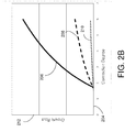
- FIG. 2B illustrates connection growth 212 trends per connection degree 204 for a natural person 206, a possible immigrant 208, and a synthetic identity 210, corresponding to the number of connections per degree as shown in FIG. 2A .
- the growth i.e., number of connections per degree
- the growth is substantially higher for the natural person 206 compared with the growth for the synthetic identity 210.
- a difference (or delta) between starting and ending growth ratios may be calculated as follows:
- the lowest degree path may be calculated as follows:
- FIG. 2C illustrates connection growth rates 212 per connection degree 204 for example natural persons 214, 216; example possible immigrants 218, 220; and example synthetic identities 222, 224 as a function of the connection degree.
- a threshold may be utilized to distinguish between synthetic identities and real entities. For example, a growth rate at the 4 th connection degree that is less than about 1.5 may indicate a synthetic identity. Similarly, a growth rate at the 5 th connection degree that is less than about 2.0 may indicate a synthetic identity. Certain implementations of the disclosed technology may utilize thresholds at one or more connection degrees to identify synthetic identities.
- an entity graph may be determined for every known entity in a population.
- embodiments of the disclosed technology may be utilized to determine entity graphs for each of the approximately 280 million known and unique entity representations in the United States.
- entity networks for each of the 280 million entity representations may be determined out to about degree 4, resulting in about 2 billion records.
- Certain example implementations of the disclosed technology may calculate the growth rates for each of the records at each degree to determine entity representations that are actually or likely synthetic identities.
- an entity's entity graph may include individuals who are related in some way, including, but not limited to family, business associates, friends, past roommates, etc.
- locations, addresses, or regions of an activity may be compared with current home and/or work addresses for the people in an individual's entity network.
- a distance may be calculated between such locations.
- data may be utilized to identify certain patterns, confidence values, scores, etc.
- all members of the entity network may be considered. In other example implementations, only individuals having certain connection criteria may be considered to reduce the computation complexity.
- an entity's network graph may be determined based on public record information including, but not limited to housing records, vehicular records, marriage records, divorce records, hospital records, birth records, death records, court records, property records, employment records, business records, address records, tax records, corporate records, etc.
- Certain embodiments of the disclosed technology may provide improved accuracy over conventional systems and techniques.
- law enforcement departments attempting to identify perpetrators of certain fraudulent activities may utilize conventional focused analysis techniques that examine each event in isolation.
- the conventional techniques typically utilize high thresholds to filter the large number of events to be analyzed.
- a high degree of suspicious activity may be required in order to identify individuals or entities associated with the activity.
- conventional techniques may have too many potentially fraudulent events to investigate.
- entities using conventional techniques often overlook collusion from groups that are able to stay below these high thresholds with respect to certain suspicious activities.
- the system and methods disclosed herein may be capable of efficiently leveraging readily available data to help detect individuals involved with generating synthetic identities, with a very low rate of false positives.
- a domain of entities may be identified for analysis. For example, data associated with a large number (perhaps hundreds of millions) of individuals may be gathered for analysis.
- the data may include identities of individuals, organizations, companies, etc.
- the data may include information such as a physical address and/or relationship information. According to certain example embodiments of the disclosed technology, one or more types of relationships between the entities may then be collected.
- a filtering mechanism may operate against the networks and may retain those networks that have outlying behavior.
- Such filtering may conventionally utilize graph-or network analysis, and queries/filtering of this form may utilize sub-graph matching routines or fuzzy sub-graphs matching.
- sub-graph matching routines or fuzzy-sub-graphs matching techniques may be NP-complete, and thus, impractical for analyzing large sets of data.
- the most notable characteristic of NP-complete problems is that no fast solution to them is known. That is, the time required to solve the problem using any currently known algorithm increases very quickly as the size of the problem grows. This means that the time required to solve even moderately sized versions of many of these problems can easily reach into the billions or trillions of years, using any amount of computing power available today.
- Embodiments of the disclosed technology may be utilized to determine or provide connections between entities even though the set of data analyzed may be extremely large.
- entities may be identified and may include people, companies, places, objects, virtual identities, etc.
- relationships may be formed in many ways, and with many qualities. For example, co-occurrence of values in common fields in a database may be utilized, such as the same last name. Relationships may also be formed using multiple co-occurrence of an entity with one or more other properties, such as people who have lived at two or more addresses.
- Relationships may also be formed based on a high reoccurrence and/or frequency of a common relationship, according to an example embodiment. For example, records of person X sending an email to person Y greater than N times may indicate a relationship between person X and person Y. In another example embodiment, if person X sends an email to or receives an email from person Y, and within a short period of time, person Z sends an email or receives an email from person Y, then a relationship may be implied between person X and person Z.
- relationships between entities may comprise Boolean, weighted, directed, undirected, and/or combinations of multiple relationships.
- clustering of the entities may rely on relationships steps.
- entities may be related by at least two different relationship types.
- relationships for the network connection analysis may be established by examining weights or strengths of connections between entities in certain directions and conditional upon other relationships, including temporal relationships. For example, in one embodiment, the directional relationships between entities X, Y, and Z may be examined and the connection between X, Y, and Z may be followed if there is a link between Y and Z that happened (in time) after the link was established between X and Y.
- networks may be scored.
- a threshold may be utilized to identify networks of interest.
- a model may be utilized to compute a number of statistics on each network.
- the model may be as simple as determining counts.
- the model may detect relationships within a network, for example, entities that are related to the centroid of the network that are also related to each other. This analysis may provide a measure of cohesiveness of relationships that exist inside the network.
- scoring and weighting of each network may be utilized to determine which networks rise above a particular threshold, and may be classified as "interesting.”
- scoring and weighting of the determined statistics may be accomplished using a heuristic scoring model, such as linear regression, neural network analysis, etc.
- Example implementations of the disclosed technology can utilize special-purpose computing systems and custom query language(s) in the processes described herein to provide meaningful results, as may be necessitated due to the sheer amount of data that needs to be tracked and analyzed.
- Certain example implementations of the disclosed technology provide tangible improvements in computer processing speeds, memory utilization, and/or programming languages. Such improvements provide certain technical contributions that can enable the detection of relationships among individuals.
- the improved computer systems disclosed herein may enable analysis of an entire population, such as all known persons in the United States, together with associated activities. The computation of such a massive amount of data, at the scale required to provide effective outlier detection and information, has been enabled by the improvements in computer processing speeds, memory utilization, and/or programming language as disclosed herein.
- Certain example implementations of the disclosed technology may be enabled a special purpose HPCC systems in combination with a special purpose software linking technology called Scalable Automated Linking Technology (SALT).
- SALT and HPCC are developed and offered by LexisNexis Risk Solutions, Inc., the assignee of the disclosed technology.
- HPCC Systems for example, provide data-intensive supercomputing platform(s) designed for solving big data problems.
- the HPCC Platform offers a consistent, single architecture for efficient processing.
- the SALT modules in conjunction with the HPCC Systems, provides technical improvements in computer processing that enable the disclosed technology and provides useful, tangible results that may have previously been unattainable.
- certain example implementation of the disclosed technology may process massive data sets, which are computationally intensive, requiring special software and hardware.
- One of the issues that has plagued previous "relationship determination” solutions involving massive data sets is the extremely long run-times and large amount of memory/disk space required.
- One of the technical solutions provided by the technology disclosed herein concerns the enablement and efficiency improvement of computer systems and software to process relationship data, and to provide the desired data in a reasonable amount of time.
- Certain example implementations of the disclosed technology may be utilized to increase the efficiency of detection of identity-based fraud indicators such as the generation and use of synthetic identities.
- SALT provides a process in which light-weight self-joins may be utilized, for example, in generating embeddable common lisp (ECL). But disk-space utilization might still be high.
- Certain example implementations of the disclosed technology may enable a core join to be split into parts, each of which is persisted. This has the advantage of breaking a potentially very long join into n parts while allowing others a time slice. This has an effect of reducing disk consumption by a factor of n, provided the eventual links are fairly sparse. In terms of performance, it should be noted that if n can be made high enough that the output of each join does not spill to disk, the relationship calculation process may have significantly faster performance.
- linking of records may be performed by certain additional special programming and analysis software.
- record linking fits into a general class of data processing known as data integration, which can be defined as the problem of combining information from multiple heterogeneous data sources.
- Data integration can include data preparation steps such as parsing, profiling, cleansing, normalization, and parsing and standardization of the raw input data prior to record linkage to improve the quality of the input data and to make the data more consistent and comparable (these data preparation steps are sometimes referred to as ETL or extract, transform, load).
- SALT can provide data profiling and data hygiene applications to support the data preparation process.
- SALT provides a general data ingest application which allows input files to be combined or merged with an existing base file.
- SALT may be used to generate a parsing and classification engine for unstructured data which can be used for data preparation. The data preparation steps are usually followed by the actual record linking or clustering process.
- SALT provides applications for several different types of record linking including internal, external, and remote.
- SALT uses advanced concepts such as term specificity to determine the relevance/weight of a particular field in the scope of the linking process, and a mathematical model based on the input data, rather than the need for hand coded user rules, which may be key to the overall efficiency of the method.
- SALT may be used to prevent fraud by verifying identities, addresses and other factors, and using information on relationships to see where collusive activities might exist.
- a persistent data structure may be utilized as part of splitting a core join, for example, to increase the performance of the computer processor and/or to reduce the disc/memory utilization requirements in determining relationships among records.
- the persistent data structure is a data structure that preserves the previous version of itself when it is modified. Such data structures may be effectively immutable, as their operations do not update the structure in-place, but instead may yield a new updated structure. Certain example implementations may utilize a meld or merge operation that can create a new version from two previous versions.
- the persistent data structure(s) can also be created using in-place updating of data and these may, in general, use less time or storage space than their purely functional counterparts.
- persistence can be achieved by simple copying.
- Certain example implementations of the disclosed technology exploit a similarity between the new and old versions to share structure between versions.
- Certain embodiments of the disclosed technology may enable the detection of possible, probable, and/or actual synthetic identity-related fraud, for example, as associated with a request for credit, payment, or a benefit.
- Certain example implementations provide for disambiguating input information and determining a likelihood of a synthetic identity.
- input information associated with an entity network may be processed, weighted, scored, etc., for example, to disambiguate the information.
- Certain implementations, for example, may utilize one or more input data fields to verify or correct other input data fields.
- data may be received from a first information source that is associated with the entity.
- a first information source that is associated with the entity.
- an entity may submit an application for certain benefits, services, credit, etc., and the application may contain certain identifying information received from the entity, such as name, social security number, address, etc.
- This "application information" may be considered as coming from the first information source, either directly from the entity, or via a vendor, business, governmental agency, etc.
- independent data from a second information source may be received to check or verify the entity supplied data that is received from the first information source.
- the independent information from the second source is not provided by the entity.
- all or a part of the entity-supplied information (such as received from the first information source) may be at least partially utilized in the generation of the independent information.
- a request for an activity may be utilized as input data.
- a request may be for a tax refund.
- the request may include a requesting person's name, street address, and social security number (SSN), where the SSN has a typographical error (intentional or unintentional).
- SSN social security number
- one or more public or private databases may be searched to find reference records matching the input information. But since the input SSN is wrong, a reference record may be returned matching the name and street address, but with a different associated SSN.
- the input information may be flagged, weighted, scored, and/or corrected based on one or more factors or metrics, including but not limited to: fields in the reference record(s) having field values that identically match, partially match, mismatch, etc., the corresponding field values.
- Example embodiments of the disclosed technology may reduce false positives and increase the probability of identifying and stopping fraud based on one or more synthetic identities.
- a model may be utilized to process identity-related input information against reference information (for example, as obtained from one or more public or private databases) to determine whether the input identity being presented corresponds to a real identity, the correct identity, and/or a possibly synthetic identity.
- Certain example implementations of the disclosed technology may determine or estimate a probability of a synthetic identity based upon a set of parameters.
- the parameters may be utilized to examine the input data, such as name, address and social security number, for example, to determine if such data corresponds to a real identity.
- the input data may be compared with the reference data, for example, to determine field value matches, mismatches, weighting, etc.
- the input data (or associated entity record) may be scored to indicate the probability that it corresponds to a real identity.
- a model may be utilized to score the input identity elements, for example, to look for imperfections in the input data. For example, if the input data is scored to have a sufficiently high probability that it corresponds to a real identity, even though there may be certain imperfections in the input or reference data, once these imperfections are found, the process may disambiguate the data. For example, in one implementation, the disambiguation may be utilized to determine how many other identities are associated with the input SSN. According to an example implementation, a control for relatives may be utilized to minimize the number of similar records, for example, as may be due to Jr. and Sr. designations.
- the container data may be utilized to derive a date-of-birth, for example, based on matching reference records.
- the derived date-of-birth may be compared with the issue date of the SSN. If the dates of the SSN are before the DOB, then the flag may be appended for this record as indication of fraud.
- FIG. 3 depicts a block diagram of an illustrative computer system architecture 300 according to an example implementation of the disclosed technology.
- Various implementations and methods herein may be embodied in non-transitory computer readable media for execution by a processor.
- the architecture 300 is provided for example purposes only and does not limit the scope of the various implementations of the communication systems and methods.
- the system architecture 300 may be embodied in specialized HPCC Systems, as developed and offered by LexisNexis Risk Solutions, Inc., the assignee of the disclosed technology. HPCC Systems, for example, provide data-intensive supercomputing platform(s) designed for solving big data problems.
- Various implementations and methods herein may be embodied in non-transitory computer readable media for execution by a processor.
- the architecture 300 of FIG. 3 includes a central processing unit (CPU) 302, where computer instructions are processed; a display interface 304 that acts as a communication interface and provides functions for rendering video, graphics, images, and texts on the display.
- the display interface 304 may be directly connected to a local display.
- the display interface 304 may be configured for providing data, images, and other information for an external/remote display or computer that is not necessarily connected to the particular CPU 302.
- the display interface 304 may wirelessly communicate, for example, via a Wi-Fi channel or other available network connection interface 312 to an external/remote display.
- the architecture 300 may include a keyboard interface 306 that provides a communication interface to a keyboard; and a pointing device interface 308 that provides a communication interface to a pointing device, mouse, and/or touch screen.
- Example implementations of the architecture 300 may include an antenna interface 310 that provides a communication interface to an antenna; a network connection interface 312 that provides a communication interface to a network.
- the display interface 304 may be in communication with the network connection interface 312, for example, to provide information for display on a remote display that is not directly connected or attached to the system.
- a camera interface 314 may be provided that may act as a communication interface and/or provide functions for capturing digital images from a camera.
- a sound interface 316 is provided as a communication interface for converting sound into electrical signals using a microphone and for converting electrical signals into sound using a speaker.
- a random-access memory (RAM) 318 is provided, where computer instructions and data may be stored in a volatile memory device for processing by the CPU 302.
- the architecture 300 includes a read-only memory (ROM) 320 where invariant low-level system code or data for basic system functions such as basic input and output (I/O), startup, or reception of keystrokes from a keyboard are stored in a non-volatile memory device.
- the architecture 300 includes a storage medium 322 or other suitable type of memory (e.g.
- the application programs 326 may include instructions for organizing, storing, retrieving, comparing, and/or analyzing the various connections associated with the properties and entities associated with embodiments of the disclosed technology.
- the analysis system, the clustering unit, and/or the scoring unit may be embodied, at least in part, via the application programs 326 interacting with data from the ROM 320 or other memory storage medium 322, and may be enabled by interaction with the operating system 324 via the CPU 302 and bus 334.
- the architecture 300 includes a power source 330 that provides an appropriate alternating current (AC) or direct current (DC) to power components.
- the architecture 300 may include and a telephony subsystem 332 that allows the device 300 to transmit and receive sound over a telephone network.
- the constituent devices and the CPU 302 communicate with each other over a bus 334.
- the CPU 302 has appropriate structure to be a computer processor.
- the computer CPU 302 may include more than one processing unit.
- the RAM 318 interfaces with the computer bus 334 to provide quick RAM storage to the CPU 302 during the execution of software programs such as the operating system application programs, and device drivers. More specifically, the CPU 302 loads computer-executable process steps from the storage medium 322 or other media into a field of the RAM 318 in order to execute software programs. Data may be stored in the RAM 318, where the data may be accessed by the computer CPU 302 during execution.
- the device 300 includes at least 128 MB of RAM, and 256 MB of flash memory.
- the storage medium 322 itself may include a number of physical drive units, such as a redundant array of independent disks (RAID), a floppy disk drive, a flash memory, a USB flash drive, an external hard disk drive, thumb drive, pen drive, key drive, a High-Density Digital Versatile Disc (HD-DVD) optical disc drive, an internal hard disk drive, a Blu-Ray optical disc drive, or a Holographic Digital Data Storage (HDDS) optical disc drive, an external mini-dual in-line memory module (DIMM) synchronous dynamic random access memory (SDRAM), or an external micro-DIMM SDRAM.
- RAID redundant array of independent disks
- HD-DVD High-Density Digital Versatile Disc
- HD-DVD High-Density Digital Versatile Disc
- HDDS Holographic Digital Data Storage
- DIMM mini-dual in-line memory module
- SDRAM synchronous dynamic random access memory
- micro-DIMM SDRAM an external micro-DIMM SDRAM
- Such computer readable storage media allow the device 300 to access computer-executable process steps, application programs and the like, stored on removable and non-removable memory media, to off-load data from the device 300 or to upload data onto the device 300.
- a computer program product, such as one utilizing a communication system may be tangibly embodied in storage medium 322, which may comprise a machine-readable storage medium.
- the special-purpose hardware and instruction set may enable processing of a massive number of records to detect indicators of fraudulent activity.
- the number of records when the initial data build is assembled can approach or exceed 3 billion records in number.
- these records may be processed by SALT to produce a relative build that can result in even more records and relationships.
- the number of records in the relative build can approach or exceed 30 billion records in number.
- the relative build records may be post-processed to provide a reduced set of records (for example approximately 14 billion records). This reduction in the number of records can be a result of eliminating duplicates, scrubbing data, correcting data errors, removing records having low accuracy or linkage confidence etc.
- the reduced set of records can include relationship type, relationship history, linkages among individual IDs, etc.
- relationship linking may be calculated via graph analytics with the Knowledge Engineering Language (KEL) and/or SALT, as previously discussed, which may provide certain speed, efficiency, and/or memory utilization advantages over previous computation languages.
- KEL Knowledge Engineering Language
- SALT Knowledge Engineering Language
- Certain example implementations of the disclosed technology may enable identification of errors in data.
- data provided by information vendors can include errors that, if left undetected, could produce erroneous results.
- Certain example implementations of the disclosed technology may be used to measure the accuracy and/or quality of the available data, for example by cross-checking, so that the data be included, scrubbed, corrected, or rejected before utilizing such data in the full analysis.
- data quality may be determined and/or improved by one or more of cross checking, scrubbing to correct errors, and scoring to use or reject the data.
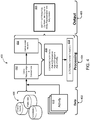
- FIG. 4 is a block diagram of an entity network growth rate calculation process 400, according to an example embodiment of the disclosed technology.
- the process 400 may fetch and/or receive a plurality of data 402 to be analyzed.
- a portion of the data 402 may be stored locally.
- all or a portion of the data may be available via one or more local or networked databases 408.
- the data 402 may be processed 404, and output 406 may be generated.
- the data 402 may include information about shared assets, cohabitation, and/or additional public data that may be indicative of a connection between two entity representations.
- the data 402 may include activity information 410 associated with some or all of the entity representations, including but not limited to time-frames in which particular addresses are associated with corresponding identities.
- the process 400 may receive the data 402 in its various forms and may process 404 the data 402 to derive relationships and connections 412.
- the relationships may be utilized to derive an entity network 414 of some or all of the entity representations.
- the data used to derive the relationships, connections 412 and entity networks 414 may be checked or corroborated 416 for self-consistency, for example, by comparing age of emergence, age of the entity data fingerprint, and the age of the entity. If such data is inconsistent, the associated records may be flagged.
- Certain example implementations of the disclosed technology may enable identification of errors in data. For example, data provided by information vendors can include errors that, if left undetected, could produce erroneous results.
- Certain example implementations of the disclosed technology may be used to measure the accuracy and/or quality of the available data, for example by cross-checking, so that the data be included, scrubbed, corrected, or rejected before utilizing such data in deriving entity network connections.
- data quality may be determined and/or improved by one or more of cross checking, scrubbing to correct errors, and scoring to use or reject the data.
- the derived entity networks 414 may be processed to determine growth 418 of the networks, as previously discussed.
- the determined growth 418 may be processed 406 to produce and output 406, which may include entity attributes 420 such as a score of likelihood that the entity is a synthetic identity, entity representation information for the synthetic identity, and/or an indication of a possible creator of the synthetic identity.
- the process 400 may leverage publicly available data, which may include several hundred million records.
- the process 400 may also clean and standardize data to reduce the possibility that matching entities are considered as distinct. Before creating a graph, the process 400 may use this data to build a large-scale network of the population in question and its associated connections.
- the process 400 may leverage a relatively large-scale of supercomputing power and analytics to target organized collusion.
- Example implementation of the disclosed technology of the systems and methods disclosed herein may rely upon large scale, special-purpose, parallel-processing computing platforms to increase the agility and scale of solutions.
- Example implementations of the disclosed technology of the systems and methods disclosed herein may measure behavior, activities, and/or relationships to actively and effectively expose syndicates and rings of collusion. Unlike many conventional systems, the systems and methods disclosed herein need not be limited to activities or rings operating in a single geographic location, and it need not be limited to short time periods. The systems and methods disclosed herein may be used to determine whether the generation of synthetic identities fall within an organized ring or certain geographical location.
- a filter may be utilized to reduce the data set to identify groups that evidence the greatest connectedness based on the scoring algorithm.
- systems and methods disclosed herein may utilize scores that match or exceed a predetermined set of criteria may be flagged for evaluation.
- filtering may utilize one or more target scores, which may be selected based on the scoring algorithm.
- geoentity networks having scores greater than or equal to a target score may be flagged as being potentially collusive.
- the method 500 starts in block 502, and according to an example implementation includes selecting, from a population of entity representations in an electronic database, a first entity representation.
- the method 500 includes identifying one or more network chains formed by one or more connections between the first entity representation, a second entity representation, and zero or more intervening entity representations.
- the method 500 includes determining a number of connections per connection degree for a predetermined number of degrees in at least one of the identified one or more network chains.
- the method 500 includes determining, based on the number of connections per connection degree, an indication that one or more of the first entity representation, the second entity representation, and zero or more of the intervening entity representations is a synthetic identity. In block 510, the method 500 includes outputting entity representation information of one or more entities in the population that are indicated as a synthetic identity.
- determining the number of connections per connection degree can include determining a shortest network chain of the identified one or more network chains; and determining the number of connections for each connection degree in the shortest network chain.
- determining an indication that one or more of the first entity representation, the second entity representation, and zero or more of the intervening entity representations is a synthetic identity is further based on establishment dates of the one or more connections.
- the one or more connections can include one or more of relative connections, business associate connections, social network connections, common asset connections, and historical address connections.
- a system graph may be utilized to determine the one or more connections, wherein the system graph comprises information associated with one or more public records including one or more of housing records, vehicular records, marriage records, divorce records, hospital records, death records, court records, property records, employment records, business records, address records, tax records, corporate records, incarceration records, and utility records, wherein the utility records comprise one or more of utility hookups, disconnects, and associated service addresses.
- the one or more connections are based at least in part on a distance between geographical regions proximate to a plurality of locations associated with one or more activities common to the entity representations.
- Certain example implementations of the disclosed technology may further include determining geometric growth ratios of the one or more connections between the first entity representation, the second entity representation, and the zero or more intervening entity representations, and wherein the indication is further based on the determined geometric growth ratios.
- the indication may be further based on differences between the determined geometric growth ratios.
- the population of entity representations can include 10 million or more entities.
- the predetermined number of degrees is five or less.
- the method 600 starts in block 602, and according to an example implementation includes determining one or more records indicating a connection of a first entity representation to a second entity representation.
- the method 600 includes identifying one or more network chains formed by at least the first entity representation, the second entity representation, and one or more subsequent entity representations indirectly connected to the selected first entity representation via the second entity representation.
- the method 600 includes determining connection dates associated with each connection in the one or more identified network chains.
- the method 600 includes determining a rate of growth of the one or more identified network chains based on the connection dates.
- the method 600 includes identifying, based on the determined rate of network chain growth, an indication of a likelihood that one or more of the first entity and the second entity is associated with a synthetic identity. In block 612, the method 600 includes outputting entity representation information of one or more entities in the population that are indicated as a synthetic identity.
- Certain example implementations of the disclosed technology may further include storing in a third field of a record associated with the selected first entity representation, an indication of the determined highest rate of growth associated with identified network chains that include the second entity representation.
- determining the one or more records indicating a connection of the selected first entity representation to the second entity representation comprises determining a lowest-order degree connection based at least in part on an earliest date of one or more connection establishment dates.
- first-degree connection of the first entity representation to a second entity representation can include one or more of relative connections, business associate connections, entity network connections, and historical address connections.
- a system graph is utilized to determine a first-degree connection of the first entity representation to a second entity representation.
- the system graph can include information associated with one or more public records including one or more of housing records, vehicular records, marriage records, divorce records, hospital records, death records, court records, property records, employment records, business records, address records, tax records, corporate records, incarceration records, and utility records, wherein the utility records comprise one or more of utility hookups, disconnects, and associated service addresses.
- a connection of the first entity representation to a second entity representation is based at least in part on a distance between geographical regions proximate to a plurality of locations associated with one or more activities common to both the first and second entity representations.
- the rate of growth is based on a number of connections and dates of the connections.
- Certain example implementations of the disclosed technology may include ordering entity representations by growth rate.
- Certain example implementations of the disclosed technology may include outputting indications identifying entity representations having a growth rate above a selected threshold.
- the population of entity representations can include 10 million or more entities.
- Certain implementations of the disclosed technology may be used to identify potential organizations of identity theft, fraud, or other activities which may be spread-out geographically.
- the input data for the system graph may be derived from historical address history of a population to be examined and such address history may be used to link individuals based on, for example, familial, residential, and business relationships.
- Embodiments of the disclosed technology may use such information to determine connections, weight metrics, and/or score the data.
- certain technical effects can be provided, such as creating certain systems and methods that are able to identify someone who is connected to various other entities.
- Embodiments of the disclosed technology may be utilized to examine the entity network growth at various degrees of separation to identify possible synthetic identities.
- certain technical effects can be provided, such as creating certain systems and methods that are able to identify someone who has generated a synthetic identity.
- some features considered for determining connections with respect to embodiments disclosed may include the number of people in one's social, family, or business network who live or work close proximity; the geographical spread of one's entity network; and the rate of identity misrepresentation in one's network. Analysis of these features, according to an example embodiment, may enable the system to identify, among others, social, family, or business networks that have a high correlation with fraudulent activity. As indicated previously, such incidents may be associated with synthetic identities, but embodiments disclosed may apply to other applications in which entity network growth rates may be utilized for identifying certain individuals.
- Various embodiments of the systems and methods disclosed herein may be embodied, in whole or in part, in a computer program product stored on non-transitory computer-readable media for execution by one or more processors. It will thus be understood that various aspects of the disclosed technology may comprise hardware or software of a computer system, as discussed above with respect to FIG. 3 . It will also be understood that, although these units may be discussed herein as being distinct from one another, they may be implemented in various ways. The distinctions between them throughout this disclosure are made for illustrative purposes only, based on operational distinctiveness.
- an example may be used to identify potential activity related to credit card application misrepresentation, identity fraud, investment fraud, crimes, business fraud, mail and/or delivery fraud, and various other various types of activities that might involve geographical information, shared assets, cohabitation and/or other entity network connections.
- RELATIONSHIP re / ationshipname: BASIS( FieldList ):DEDUP( FieldList ) [:SCORE( FieldList )][:TRACK(FieldList)IMULTIPLE( n )li:SPLIT( n )] [:THRESHOLD(n)][:BLOCKTHRESHOLD(n)]
- RELATIONSHIP relationshipname:RelationshipList [:MULTIPLE( n )] [:THRESHOLD(n)] [:BLOCKTHRESHOLD(n)] [:LINK(NONEIALLIDIRECTICROSS)]
- SALT internal linking provides the capability to cluster together records to form an entity.
- the objective is not to determine that two records or clusters are close enough to become part of the same entity, but to determine if a statistically significant link exists between the two clusters and to record this relationship.
- the RELATIONSHIP statement provides this function.
- the relationship file can be deduped and projected so that ID1 ID2 and ID2 ID1 are both in the file, then use an ATTRIBUTEFILE statement that declares one ID as the IDFIELD and the other ID as the VALUES field. See description below of the output format for a relationship file.
- the core part of a SALT relationship is the BASIS; the basis is the list of fields which must be identical between two clusters for a linkage to exist. Fields following a :?: field in the basis field list must be identical or one must be null. Thus a relationship which counts and weighs the number of shared addresses between two clusters could be:
- the DEDUP performs a smart dedup, it will actually look for the strongest link found for a given value of a DEDUP field. In the example presented above, if a link had been found with and without the sec_range it will use the one which includes the sec-range value. If DEDUP is omitted, it defaults to the whole of the basis. SALT also checks to insure that all DEDUP elements are from the BASIS definition.
- a linkage is declared if the internal linking match threshold is exceeded. This can be overridden using the THRESHOLD parameter on the RELATIONSHIP statement. As addresses usually have a specificity of around 28 it will generally then take 2 or more to cause a relationship to be declared. If you wish to force that a certain number of different links need to be found between clusters before declaring a relationship then you can use the :MULTIPLE(n) option. Here n is the minimum number of linkages that must have been found. A linkage occurs between any two entity identifiers which share a common value for a given basis.
- the fields in the score list are independent and will be maximized across all of the linkages taking part in one relationship (if more than one RELATIONSHIP statement have the same field in the SCORE list, the highest score for that field will be used for all RELATIONSHIP statements).
- RELATIONSHIP It is possible to have multiple RELATIONSHIP statements defined in one specification file. Each RELATIONSHIP is independently computed. The output for the relationship specified will be in the following format:
- ID1 and ID2 are the entity IDs being linked.
- the Basis_score is the accumulated score across all of the (deduped) basis matches that form the relationship.
- the Dedup_Val field is used for computation and may be ignored.
- Cnt is the number of different basis matches being used in the relationship. Then will come a score for each score field which has been maximized across all the basis matches in the relationship.
- the total score used to determine whether or not the matching threshold is exceeded is Basisscore + Lnamescore + SSN score.
- BASIS or SCORE Any field (BASIS or SCORE) which is part of a CONCEPT definition will be weighted appropriately when used inside BASIS or SCORE.
- the system will then track for a 'first' date - the first date that BOTH elements of a relationship have a fact. For a 'last' date in is the last date that BOTH elements of a relationship share that fact. If a relationship is based upon multiple co-incidences it will find the earliest shared fact for a 'first' date and the latest shared fact for a last date. This is a slightly weird combination of mins and maxes - but semantically it works. As an example:
- the system first computes the 'fact coincidence dates:
- the two record-dates may be TRACKed if required (or not).
- ReportedDate can now be used as a (fairly) 'regular' field in the basis or score portion of a relationship. eg:
- MULTIPLE and THRESHOLD parameters are applied to the child relationship.
- MULTIPLE(3) will require 3 different data matches to have occurred between COHABIT and COSSN.
- a relationship service is built for each relationship that is not the child of another one.
- This service takes a UID (unique id) and a depth and will produce rolled up data for every relationship in the tree that many levels deep.
- the tree walking aspect of this service is in the relationship_links module. The tree is walked so that each level of the tree is joined to the branch before via the strongest link. At each level the IDI is the node being walked from and the ID2 is the node being walked to. The original node appears as a level 0 entry in ID2.
- Result 1 [2 rows] Key:: salt test7:: bdid: :rel:cofein Result 2 [120 rows ⁇ Key::salt test7::bdid::rel:assoc Match Sample Records Slice Cut Candidates Specificities SPC Shift Pre Clusters Post Clusters Pre Cluster Count Post Cluster Count Matches Performed 305 Basic Matches Performed 132 Slices Performed 14 Rule Efficacy [7 rows ⁇ Confidence Levels [73 rows] Propagation Assisted Pcnt 17.04918032786885 Propagation Required Pcnt 5.573770491803279 Pre Pop Stats [1 rows] Post Pop Stats [1 rows] Validity Statistics [1 rows] Id Consistency4 [1 rows] Result 22 [1 rows] kev::salt test7::bdid::debug::specificities debug
- This file contains the following results: bdid1 bdid2 basis score dedup val cnt company name score 1 37178850 292680203 22 54286 2 11 2 292680203 37178850 22 54286 2 11 Result 2 is the file produced by the top-level relationship called ASSOC.
Landscapes
- Engineering & Computer Science (AREA)
- Business, Economics & Management (AREA)
- Theoretical Computer Science (AREA)
- Physics & Mathematics (AREA)
- General Physics & Mathematics (AREA)
- Databases & Information Systems (AREA)
- Computer Security & Cryptography (AREA)
- General Engineering & Computer Science (AREA)
- Accounting & Taxation (AREA)
- Strategic Management (AREA)
- General Business, Economics & Management (AREA)
- Finance (AREA)
- Tourism & Hospitality (AREA)
- Data Mining & Analysis (AREA)
- Economics (AREA)
- Marketing (AREA)
- Computer Hardware Design (AREA)
- Development Economics (AREA)
- Computing Systems (AREA)
- General Health & Medical Sciences (AREA)
- Signal Processing (AREA)
- Health & Medical Sciences (AREA)
- Computer Networks & Wireless Communication (AREA)
- Human Resources & Organizations (AREA)
- Software Systems (AREA)
- Primary Health Care (AREA)
- Educational Administration (AREA)
- Entrepreneurship & Innovation (AREA)
- Technology Law (AREA)
- Bioethics (AREA)
- Operations Research (AREA)
- Quality & Reliability (AREA)
- Management, Administration, Business Operations System, And Electronic Commerce (AREA)
Claims (15)
- Computerimplementiertes Verfahren zum Identifizieren einer oder mehrerer synthetischer Identitäten unter einer Population von Entitätsdarstellungen in einer elektronischen Datenbank, wobei jede Entitätsdarstellung eine Mehrzahl von Datensätzen umfasst, wobei jeder Datensatz eine Mehrzahl von Feldern umfasst, wobei mindestens ein erstes Feld der Mehrzahl von Feldern geeignet ist, eine Verbindung zu einer Kohortenentitätsdarstellung in der Population anzuzeigen, wobei das Verfahren durch mindestens einen Prozessor durchgeführt wird, der konfiguriert ist, um auf die elektronische Datenbank zuzugreifen, wobei das Verfahren umfasst:Auswählen einer ersten Entitätsdarstellung aus der Population von Entitätsdarstellungen;für die ausgewählte erste Entitätsdarstellung:Identifizieren einer oder mehrerer Netzwerkketten, die durch eine oder mehrere Verbindungen zwischen der ersten Entitätsdarstellung, einer zweiten Entitätsdarstellung und null oder mehr dazwischenliegenden Entitätsdarstellungen gebildet sind; undBestimmen einer Anzahl von Verbindungen pro Verbindungsgrad für eine vorgegebene Anzahl von Graden in mindestens einer der identifizierten ein oder mehreren Netzwerkketten;Bestimmen von geometrischen Wachstumsraten der ein oder mehreren Verbindungen zwischen der ersten Entitätsdarstellung, der zweiten Entitätsdarstellung und den null oder mehr dazwischenliegenden Entitätsdarstellungen auf der Grundlage der Anzahl von Verbindungen pro Verbindungsgrad, wobei die einem gegebenen Verbindungstrennungsgrad d zugeordnete geometrische Wachstumsrate r bestimmt ist durch:
 Bestimmen, basierend auf den bestimmten geometrischen Wachstumsraten unterhalb eines Schwellenwertes, einer Angabe, dass eine oder mehrere unter der ersten Entitätsdarstellung, der zweiten Entitätsdarstellung und null oder mehr der dazwischenliegenden Entitätsdarstellungen eine synthetische Identität ist/ sind; undAusgeben von Entitätsdarstellungsinformation von einer oder mehreren Entitäten in der Population, die als eine synthetische Identität angegeben werden.
 - Verfahren nach Anspruch 1, bei dem das Bestimmen der Anzahl von Verbindungen pro Verbindungsgrad umfasst:Bestimmen einer kürzesten Netzwerkkette unter den identifizierten ein oder mehreren Netzwerkketten; undBestimmen der Anzahl der Verbindungen für jeden Verbindungsgrad in der kürzesten Netzwerkkette.
- Verfahren nach Anspruch 1 oder Anspruch 2, wobei das Bestimmen einer Angabe, dass eine oder mehrere unter der ersten Entitätsdarstellung, der zweiten Entitätsdarstellung und der null oder mehr dazwischenliegenden Entitätsdarstellungen eine synthetische Identität ist/ sind, ferner auf den Einrichtungsdaten der einen oder mehreren Verbindungen basiert.
- Verfahren nach einem der vorhergehenden Ansprüche, bei dem die ein oder mehreren Verbindungen eine oder mehrere Verbindungen von Verwandtenverbindungen, Verbindungen von Geschäftspartnern, Verbindungen von sozialen Netzwerken, Verbindungen von gemeinsamen Vermögenswerten und historischen Adressverbindungen umfassen.
- Verfahren nach einem der vorhergehenden Ansprüche, bei dem ein Systemgraph verwendet wird, um die ein oder mehreren Verbindungen zu bestimmen, wobei der Systemgraph Informationen umfasst, die einem oder mehreren öffentlichen Datensätzen zugeordnet sind, die einen oder mehrere von Wohnungsdatensätzen, Fahrzeugdatensätzen, Heiratsdatensätzen, Scheidungsdatensätzen, Krankenhausdatensätzen, Todesdatensätzen, Gerichtsdatensätzen, Eigentumsdatensätzen, Beschäftigungsdatensätzen, Geschäftsdatensätzen, Adressdatensätzen, Steuerdatensätzen, Unternehmensdatensätzen, Inhaftierungsdatensätzen und Versorgungsdatensätzen umfassen, wobei die Versorgungsdatensätze einen oder mehrere von Versorgungsanschlüssen, Trennungen und zugeordneten Dienstadressen umfassen.
- Verfahren nach einem der vorhergehenden Ansprüche, bei dem die ein oder mehreren Verbindungen zumindest teilweise auf einer Entfernung zwischen geographischen Regionen in der Nähe einer Mehrzahl von Orten beruhen, die einer oder mehreren den Entitätsdarstellungen gemeinsamen Aktivitäten zugeordnet sind.
- Verfahren nach Anspruch 1, ferner umfassend das Bestimmen von geometrischen Wachstumsverhältnissen der ein oder mehreren Verbindungen zwischen der ersten Entitätsdarstellung, der zweiten Entitätsdarstellung und den null oder mehr dazwischenliegenden Entitätsdarstellungen, und wobei die Angabe ferner auf Unterschieden zwischen den bestimmten geometrischen Wachstumsverhältnissen basiert.
- Verfahren nach einem der vorhergehenden Ansprüche, bei dem die Population der Entitätsdarstellungen 10 Millionen Entitäten oder mehr umfasst.
- Verfahren nach einem der vorangehenden Ansprüche, bei dem die vorgegebene Anzahl von Graden fünf oder weniger beträgt.
- System mit:mindestens einem Speicher zum Speichern von Daten und computerausführbaren Anweisungen; undmindestens einem Prozessor, der konfiguriert ist, um auf den mindestens einen Speicher zuzugreifen, und der ferner konfiguriert ist, um die computerausführbaren Anweisungen auszuführen, um eine oder mehrere synthetische Identitäten unter einer Population von Entitätsdarstellungen in einer elektronischen Datenbank zu identifizieren, wobei jede Entitätsdarstellung eine Mehrzahl von Datensätzen umfasst, wobei jeder Datensatz eine Mehrzahl von Feldern umfasst, mindestens ein erstes der Mehrzahl von Feldern geeignet ist, eine Verbindung zu einer Kohortenentitätsdarstellung in der Population anzuzeigen, wobei die ein oder mehr synthetischen Identitäten identifiziert werden durch:Auswählen einer ersten Entitätsdarstellung aus der Population von Entitätsdarstellungen;für die ausgewählte erste Entitätsdarstellung:Identifizieren einer oder mehrerer Netzwerkketten, die durch eine oder mehrere Verbindungen zwischen der ersten Entitätsdarstellung, einer zweiten Entitätsdarstellung und null oder mehr dazwischenliegenden Entitätsdarstellungen gebildet sind;
undBestimmen einer Anzahl von Verbindungen pro Verbindungsgrad für eine vorgegebene Anzahl von Graden in mindestens einer der identifizierten ein oder mehreren Netzwerkketten;Bestimmen von geometrischen Wachstumsraten der ein oder mehreren Verbindungen zwischen der ersten Entitätsdarstellung, der zweiten Entitätsdarstellung und den null oder mehr dazwischenliegenden Entitätsdarstellungen auf der Grundlage der Anzahl von Verbindungen pro Verbindungsgrad, wobei die einem gegebenen Verbindungstrennungsgrad d zugeordnete geometrische Wachstumsrate r bestimmt wird durch: Bestimmen, basierend auf den bestimmten geometrischen Wachstumsraten unterhalb eines Schwellenwertes, einer Angabe, dass eine oder mehrere unter der ersten Entitätsdarstellung, der zweiten Entitätsdarstellung und null oder mehr der dazwischenliegenden Entitätsdarstellungen eine synthetische Identität ist/ sind; undAusgeben von Entitätsdarstellungsinformation von einer oder mehreren Entitäten in der Population, die als eine synthetische Identität angezeigt werden.
 - System nach Anspruch 10, bei dem das Bestimmen der Anzahl von Verbindungen pro Verbindungsgrad umfasst:Bestimmen einer kürzesten Netzwerkkette unter den identifizierten ein oder mehreren Netzwerkketten; undBestimmen der Anzahl der Verbindungen für jeden Verbindungsgrad in der kürzesten Netzwerkkette.
- System nach Anspruch 10 oder Anspruch 11, bei dem das Bestimmen eines Anzeichens, dass eine oder mehrere unter der ersten Entitätsdarstellung, der zweiten Entitätsdarstellung und null oder mehr der dazwischenliegenden Entitätsdarstellungen eine synthetische Identität ist/ sind, ferner auf den Einrichtungsdaten der einen oder mehreren Verbindungen basiert.
- System nach einem der Ansprüche 10 bis 12, bei dem die ein oder mehreren Verbindungen zumindest teilweise auf einer Entfernung zwischen geographischen Regionen in der Nähe einer Mehrzahl von Orten beruhen, die einer oder mehreren den Entitätsdarstellungen gemeinsamen Aktivitäten zugeordnet sind.
- System nach einem der Ansprüche 10 bis 13, ferner umfassend das Bestimmen von geometrischen Wachstumsverhältnissen der ein oder mehreren Verbindungen zwischen der ersten Entitätsdarstellung, der zweiten Entitätsdarstellung und den null oder mehr dazwischenliegenden Entitätsdarstellungen, wobei die Angabe ferner auf den bestimmten geometrischen Wachstumsverhältnissen basiert, und wobei die Angabe ferner auf Unterschieden zwischen den bestimmten geometrischen Wachstumsverhältnissen basiert.
- Verfahren nach einem der Ansprüche 1 bis 9 oder System nach einem der Ansprüche 10 bis 14, bei dem r kleiner als 1,5 für einen Grad d von 4 eine synthetische Identität anzeigt oder r kleiner als 2,0 für einen Grad d von 5 eine synthetische Identität anzeigt.
Applications Claiming Priority (1)
| Application Number | Priority Date | Filing Date | Title |
|---|---|---|---|
| US16/033,692 US11100600B2 (en) | 2018-07-12 | 2018-07-12 | Systems and methods for entity network analytics using geometric growth rate analysis |
Publications (2)
| Publication Number | Publication Date |
|---|---|
| EP3595263A1 EP3595263A1 (de) | 2020-01-15 |
| EP3595263B1 true EP3595263B1 (de) | 2021-10-06 |
Family
ID=67437698
Family Applications (1)
| Application Number | Title | Priority Date | Filing Date |
|---|---|---|---|
| EP19185698.8A Active EP3595263B1 (de) | 2018-07-12 | 2019-07-11 | Systeme und verfahren für entitätsnetzwerkanalytik |
Country Status (3)
| Country | Link |
|---|---|
| US (1) | US11100600B2 (de) |
| EP (1) | EP3595263B1 (de) |
| CN (1) | CN110781229B (de) |
Families Citing this family (7)
| Publication number | Priority date | Publication date | Assignee | Title |
|---|---|---|---|---|
| US11574067B2 (en) * | 2019-01-28 | 2023-02-07 | Google Llc | Efficient on-device public-private computation |
| US11669840B2 (en) * | 2019-12-19 | 2023-06-06 | Yuzhen Xu | System and method for managing associations in an online network |
| US20210326475A1 (en) * | 2020-04-20 | 2021-10-21 | Replica Analytics | Systems and method for evaluating identity disclosure risks in synthetic personal data |
| CN111552680A (zh) * | 2020-04-27 | 2020-08-18 | 深圳壹账通智能科技有限公司 | 业务欺诈识别数据库的构建方法、装置和计算机设备 |
| CN111476030B (zh) * | 2020-05-08 | 2022-03-15 | 中国科学院计算机网络信息中心 | 一种基于深度学习的前瞻因子筛选方法 |
| CN112926990B (zh) * | 2021-03-25 | 2022-08-30 | 支付宝(杭州)信息技术有限公司 | 欺诈识别的方法和装置 |
| CN114910931B (zh) * | 2022-01-21 | 2025-08-01 | 中国人民解放军网络空间部队信息工程大学 | 一种基于加权二阶中心矩的诱导式欺骗检测方法 |
Family Cites Families (19)
| Publication number | Priority date | Publication date | Assignee | Title |
|---|---|---|---|---|
| US9412141B2 (en) * | 2003-02-04 | 2016-08-09 | Lexisnexis Risk Solutions Fl Inc | Systems and methods for identifying entities using geographical and social mapping |
| US8549590B1 (en) * | 2012-07-03 | 2013-10-01 | Lexisnexis Risk Solutions Fl Inc. | Systems and methods for identity authentication using a social network |
| US8386377B1 (en) * | 2003-05-12 | 2013-02-26 | Id Analytics, Inc. | System and method for credit scoring using an identity network connectivity |
| EP2487600A1 (de) * | 2004-05-04 | 2012-08-15 | Boston Consulting Group, Inc. | Verfahren und Vorrichtung zur Auswahl, Analyse und Visualisierung ähnlicher Datenbankaufnahmen als ein Netzwerk |
| JP5711750B2 (ja) * | 2009-10-06 | 2015-05-07 | コーニンクレッカ フィリップス エヌ ヴェ | 異なるエンティティに保管された患者情報記録の自律的な結合 |
| US20140046983A1 (en) * | 2011-05-05 | 2014-02-13 | Centrifuge Pty Ltd | Data Analysis |
| US9917739B2 (en) * | 2012-02-20 | 2018-03-13 | Aptima, Inc. | Systems and methods for network pattern matching |
| US8918891B2 (en) | 2012-06-12 | 2014-12-23 | Id Analytics, Inc. | Identity manipulation detection system and method |
| US10089686B2 (en) | 2012-07-03 | 2018-10-02 | Lexisnexis Risk Solutions Fl Inc. | Systems and methods for increasing efficiency in the detection of identity-based fraud indicators |
| WO2014143624A1 (en) * | 2013-03-12 | 2014-09-18 | Lexisnexis Risk Solutions Inc. | Systems and methods for telematics control and communications |
| JP5413867B1 (ja) * | 2013-05-31 | 2014-02-12 | 国立大学法人京都大学 | 関係性グラフ相互連携システム |
| US20140358811A1 (en) * | 2013-06-04 | 2014-12-04 | International Business Machines Corporation | Illegal Activity Detection through Interpersonal Relationship Resolution |
| US9300585B2 (en) * | 2013-11-15 | 2016-03-29 | Cisco Technology, Inc. | Shortening of service paths in service chains in a communications network |
| WO2016154419A1 (en) | 2015-03-25 | 2016-09-29 | Equifax, Inc. | Detecting synthetic online entities |
| US9703986B1 (en) | 2015-05-13 | 2017-07-11 | Anonyome Labs, Inc. | Decentralized reputation service for synthetic identities |
| CN106453030B (zh) * | 2015-08-12 | 2019-10-11 | 大连民族学院 | 一种获取社交关系链的方法及装置 |
| US9967265B1 (en) * | 2015-09-29 | 2018-05-08 | EMC IP Holding Company LLC | Detecting malicious online activities using event stream processing over a graph database |
| US10346928B2 (en) * | 2015-09-30 | 2019-07-09 | Microsoft Technology Licensing, Llc | Ranking members based on influence score |
| US10979455B2 (en) * | 2017-04-24 | 2021-04-13 | Unisys Corporation | Solution definition for enterprise security management |
-
2018
- 2018-07-12 US US16/033,692 patent/US11100600B2/en active Active
-
2019
- 2019-07-11 EP EP19185698.8A patent/EP3595263B1/de active Active
- 2019-07-12 CN CN201910627379.1A patent/CN110781229B/zh active Active
Also Published As
| Publication number | Publication date |
|---|---|
| CN110781229B (zh) | 2024-11-08 |
| US20200020062A1 (en) | 2020-01-16 |
| US11100600B2 (en) | 2021-08-24 |
| EP3595263A1 (de) | 2020-01-15 |
| CN110781229A (zh) | 2020-02-11 |
Similar Documents
| Publication | Publication Date | Title |
|---|---|---|
| US10762561B2 (en) | Systems and methods for improving computation efficiency in the detection of fraud indicators for loans | |
| US10217163B2 (en) | Systems and methods for increasing efficiency in the detection of identity-based fraud indicators | |
| US11100600B2 (en) | Systems and methods for entity network analytics using geometric growth rate analysis | |
| US12373452B2 (en) | Identity resolution in big, noisy, and/or unstructured data | |
| Buczak et al. | Fuzzy association rule mining for community crime pattern discovery | |
| WO2019019630A1 (zh) | 反欺诈识别方法、存储介质、承载平安脑的服务器及装置 | |
| AU2020202889B2 (en) | Systems and methods for computing data privacy-utility tradeoff | |
| US10318964B2 (en) | Systems and methods for detecting entity migration | |
| US10223746B2 (en) | Systems and methods for inferring the performance of rejected credit applicants | |
| CN113272809B (zh) | 创建保护敏感数据的化身的方法 | |
| CN120580070B (zh) | 一种基于智能识别的金融预开户风险评估系统 | |
| Livraga et al. | Data confidentiality and information credibility in on-line ecosystems | |
| Wu et al. | Hybrid TODIM method with crisp number and probability linguistic term set for urban epidemic situation evaluation | |
| Thang et al. | Multistage System‐Based Machine Learning Techniques for Intrusion Detection in WiFi Network | |
| Christen et al. | Advanced record linkage methods and privacy aspects for population reconstruction—a survey and case studies | |
| Blue et al. | Proving yourself: addressing the refugee identity crisis with Bayesi-chain probability & digital footprints | |
| Deshmukh et al. | Fake News Detection on Datasets | |
| Takan et al. | Fair-news: digital journalism model to prevent information pollution and manipulation | |
| Senaratne | Anomaly detection in graphs for knowledge discovery and data quality enhancement | |
| US20260094161A1 (en) | Group-based fraud detection decisioning | |
| Nguyen | Debunking misinformation on the Web: Detection, validation, and visualisation | |
| Tang et al. | Random-Feature Graph Neural Networks with Representation Tokenized Transformer for Robust One-class Anomaly Detection | |
| Rajasekaran | Cross-Device Customer Identity Unification: Scalable Graph Algorithms for Multi-Channel Identity Resolution | |
| Yang et al. | Data Asset Valuation and Security | |
| Mahapatra et al. | Leveraging Multiple Online Sources for Accurate Income Verification |
Legal Events
| Date | Code | Title | Description |
|---|---|---|---|
| PUAI | Public reference made under article 153(3) epc to a published international application that has entered the european phase |
Free format text: ORIGINAL CODE: 0009012 |
|
| STAA | Information on the status of an ep patent application or granted ep patent |
Free format text: STATUS: THE APPLICATION HAS BEEN PUBLISHED |
|
| AK | Designated contracting states |
Kind code of ref document: A1 Designated state(s): AL AT BE BG CH CY CZ DE DK EE ES FI FR GB GR HR HU IE IS IT LI LT LU LV MC MK MT NL NO PL PT RO RS SE SI SK SM TR |
|
| AX | Request for extension of the european patent |
Extension state: BA ME |
|
| STAA | Information on the status of an ep patent application or granted ep patent |
Free format text: STATUS: REQUEST FOR EXAMINATION WAS MADE |
|
| 17P | Request for examination filed |
Effective date: 20200406 |
|
| RBV | Designated contracting states (corrected) |
Designated state(s): AL AT BE BG CH CY CZ DE DK EE ES FI FR GB GR HR HU IE IS IT LI LT LU LV MC MK MT NL NO PL PT RO RS SE SI SK SM TR |
|
| GRAP | Despatch of communication of intention to grant a patent |
Free format text: ORIGINAL CODE: EPIDOSNIGR1 |
|
| STAA | Information on the status of an ep patent application or granted ep patent |
Free format text: STATUS: GRANT OF PATENT IS INTENDED |
|
| GRAJ | Information related to disapproval of communication of intention to grant by the applicant or resumption of examination proceedings by the epo deleted |
Free format text: ORIGINAL CODE: EPIDOSDIGR1 |
|
| INTG | Intention to grant announced |
Effective date: 20210224 |
|
| STAA | Information on the status of an ep patent application or granted ep patent |
Free format text: STATUS: REQUEST FOR EXAMINATION WAS MADE |
|
| GRAP | Despatch of communication of intention to grant a patent |
Free format text: ORIGINAL CODE: EPIDOSNIGR1 |
|
| STAA | Information on the status of an ep patent application or granted ep patent |
Free format text: STATUS: GRANT OF PATENT IS INTENDED |
|
| INTC | Intention to grant announced (deleted) | ||
| INTG | Intention to grant announced |
Effective date: 20210423 |
|
| GRAS | Grant fee paid |
Free format text: ORIGINAL CODE: EPIDOSNIGR3 |
|
| GRAA | (expected) grant |
Free format text: ORIGINAL CODE: 0009210 |
|
| STAA | Information on the status of an ep patent application or granted ep patent |
Free format text: STATUS: THE PATENT HAS BEEN GRANTED |
|
| AK | Designated contracting states |
Kind code of ref document: B1 Designated state(s): AL AT BE BG CH CY CZ DE DK EE ES FI FR GB GR HR HU IE IS IT LI LT LU LV MC MK MT NL NO PL PT RO RS SE SI SK SM TR |
|
| REG | Reference to a national code |
Ref country code: GB Ref legal event code: FG4D |
|
| REG | Reference to a national code |
Ref country code: CH Ref legal event code: EP Ref country code: AT Ref legal event code: REF Ref document number: 1437212 Country of ref document: AT Kind code of ref document: T Effective date: 20211015 |
|
| REG | Reference to a national code |
Ref country code: IE Ref legal event code: FG4D |
|
| REG | Reference to a national code |
Ref country code: DE Ref legal event code: R096 Ref document number: 602019008110 Country of ref document: DE |
|
| REG | Reference to a national code |
Ref country code: DE Ref legal event code: R079 Ref document number: 602019008110 Country of ref document: DE Free format text: PREVIOUS MAIN CLASS: H04L0029060000 Ipc: H04L0065000000 |
|
| REG | Reference to a national code |
Ref country code: NL Ref legal event code: FP |
|
| REG | Reference to a national code |
Ref country code: LT Ref legal event code: MG9D |
|
| REG | Reference to a national code |
Ref country code: AT Ref legal event code: MK05 Ref document number: 1437212 Country of ref document: AT Kind code of ref document: T Effective date: 20211006 |
|
| PG25 | Lapsed in a contracting state [announced via postgrant information from national office to epo] |
Ref country code: RS Free format text: LAPSE BECAUSE OF FAILURE TO SUBMIT A TRANSLATION OF THE DESCRIPTION OR TO PAY THE FEE WITHIN THE PRESCRIBED TIME-LIMIT Effective date: 20211006 Ref country code: LT Free format text: LAPSE BECAUSE OF FAILURE TO SUBMIT A TRANSLATION OF THE DESCRIPTION OR TO PAY THE FEE WITHIN THE PRESCRIBED TIME-LIMIT Effective date: 20211006 Ref country code: FI Free format text: LAPSE BECAUSE OF FAILURE TO SUBMIT A TRANSLATION OF THE DESCRIPTION OR TO PAY THE FEE WITHIN THE PRESCRIBED TIME-LIMIT Effective date: 20211006 Ref country code: BG Free format text: LAPSE BECAUSE OF FAILURE TO SUBMIT A TRANSLATION OF THE DESCRIPTION OR TO PAY THE FEE WITHIN THE PRESCRIBED TIME-LIMIT Effective date: 20220106 Ref country code: AT Free format text: LAPSE BECAUSE OF FAILURE TO SUBMIT A TRANSLATION OF THE DESCRIPTION OR TO PAY THE FEE WITHIN THE PRESCRIBED TIME-LIMIT Effective date: 20211006 |
|
| PG25 | Lapsed in a contracting state [announced via postgrant information from national office to epo] |
Ref country code: IS Free format text: LAPSE BECAUSE OF FAILURE TO SUBMIT A TRANSLATION OF THE DESCRIPTION OR TO PAY THE FEE WITHIN THE PRESCRIBED TIME-LIMIT Effective date: 20220206 Ref country code: SE Free format text: LAPSE BECAUSE OF FAILURE TO SUBMIT A TRANSLATION OF THE DESCRIPTION OR TO PAY THE FEE WITHIN THE PRESCRIBED TIME-LIMIT Effective date: 20211006 Ref country code: PT Free format text: LAPSE BECAUSE OF FAILURE TO SUBMIT A TRANSLATION OF THE DESCRIPTION OR TO PAY THE FEE WITHIN THE PRESCRIBED TIME-LIMIT Effective date: 20220207 Ref country code: PL Free format text: LAPSE BECAUSE OF FAILURE TO SUBMIT A TRANSLATION OF THE DESCRIPTION OR TO PAY THE FEE WITHIN THE PRESCRIBED TIME-LIMIT Effective date: 20211006 Ref country code: NO Free format text: LAPSE BECAUSE OF FAILURE TO SUBMIT A TRANSLATION OF THE DESCRIPTION OR TO PAY THE FEE WITHIN THE PRESCRIBED TIME-LIMIT Effective date: 20220106 Ref country code: LV Free format text: LAPSE BECAUSE OF FAILURE TO SUBMIT A TRANSLATION OF THE DESCRIPTION OR TO PAY THE FEE WITHIN THE PRESCRIBED TIME-LIMIT Effective date: 20211006 Ref country code: HR Free format text: LAPSE BECAUSE OF FAILURE TO SUBMIT A TRANSLATION OF THE DESCRIPTION OR TO PAY THE FEE WITHIN THE PRESCRIBED TIME-LIMIT Effective date: 20211006 Ref country code: GR Free format text: LAPSE BECAUSE OF FAILURE TO SUBMIT A TRANSLATION OF THE DESCRIPTION OR TO PAY THE FEE WITHIN THE PRESCRIBED TIME-LIMIT Effective date: 20220107 Ref country code: ES Free format text: LAPSE BECAUSE OF FAILURE TO SUBMIT A TRANSLATION OF THE DESCRIPTION OR TO PAY THE FEE WITHIN THE PRESCRIBED TIME-LIMIT Effective date: 20211006 |
|
| REG | Reference to a national code |
Ref country code: DE Ref legal event code: R097 Ref document number: 602019008110 Country of ref document: DE |
|
| PG25 | Lapsed in a contracting state [announced via postgrant information from national office to epo] |
Ref country code: SM Free format text: LAPSE BECAUSE OF FAILURE TO SUBMIT A TRANSLATION OF THE DESCRIPTION OR TO PAY THE FEE WITHIN THE PRESCRIBED TIME-LIMIT Effective date: 20211006 Ref country code: SK Free format text: LAPSE BECAUSE OF FAILURE TO SUBMIT A TRANSLATION OF THE DESCRIPTION OR TO PAY THE FEE WITHIN THE PRESCRIBED TIME-LIMIT Effective date: 20211006 Ref country code: RO Free format text: LAPSE BECAUSE OF FAILURE TO SUBMIT A TRANSLATION OF THE DESCRIPTION OR TO PAY THE FEE WITHIN THE PRESCRIBED TIME-LIMIT Effective date: 20211006 Ref country code: EE Free format text: LAPSE BECAUSE OF FAILURE TO SUBMIT A TRANSLATION OF THE DESCRIPTION OR TO PAY THE FEE WITHIN THE PRESCRIBED TIME-LIMIT Effective date: 20211006 Ref country code: DK Free format text: LAPSE BECAUSE OF FAILURE TO SUBMIT A TRANSLATION OF THE DESCRIPTION OR TO PAY THE FEE WITHIN THE PRESCRIBED TIME-LIMIT Effective date: 20211006 Ref country code: CZ Free format text: LAPSE BECAUSE OF FAILURE TO SUBMIT A TRANSLATION OF THE DESCRIPTION OR TO PAY THE FEE WITHIN THE PRESCRIBED TIME-LIMIT Effective date: 20211006 |
|
| PLBE | No opposition filed within time limit |
Free format text: ORIGINAL CODE: 0009261 |
|
| STAA | Information on the status of an ep patent application or granted ep patent |
Free format text: STATUS: NO OPPOSITION FILED WITHIN TIME LIMIT |
|
| 26N | No opposition filed |
Effective date: 20220707 |
|
| PG25 | Lapsed in a contracting state [announced via postgrant information from national office to epo] |
Ref country code: AL Free format text: LAPSE BECAUSE OF FAILURE TO SUBMIT A TRANSLATION OF THE DESCRIPTION OR TO PAY THE FEE WITHIN THE PRESCRIBED TIME-LIMIT Effective date: 20211006 |
|
| PG25 | Lapsed in a contracting state [announced via postgrant information from national office to epo] |
Ref country code: SI Free format text: LAPSE BECAUSE OF FAILURE TO SUBMIT A TRANSLATION OF THE DESCRIPTION OR TO PAY THE FEE WITHIN THE PRESCRIBED TIME-LIMIT Effective date: 20211006 |
|
| PG25 | Lapsed in a contracting state [announced via postgrant information from national office to epo] |
Ref country code: MC Free format text: LAPSE BECAUSE OF FAILURE TO SUBMIT A TRANSLATION OF THE DESCRIPTION OR TO PAY THE FEE WITHIN THE PRESCRIBED TIME-LIMIT Effective date: 20211006 |
|
| REG | Reference to a national code |
Ref country code: CH Ref legal event code: PL |
|
| REG | Reference to a national code |
Ref country code: BE Ref legal event code: MM Effective date: 20220731 |
|
| PG25 | Lapsed in a contracting state [announced via postgrant information from national office to epo] |
Ref country code: LU Free format text: LAPSE BECAUSE OF NON-PAYMENT OF DUE FEES Effective date: 20220711 Ref country code: LI Free format text: LAPSE BECAUSE OF NON-PAYMENT OF DUE FEES Effective date: 20220731 Ref country code: FR Free format text: LAPSE BECAUSE OF NON-PAYMENT OF DUE FEES Effective date: 20220731 Ref country code: CH Free format text: LAPSE BECAUSE OF NON-PAYMENT OF DUE FEES Effective date: 20220731 |
|
| PG25 | Lapsed in a contracting state [announced via postgrant information from national office to epo] |
Ref country code: IT Free format text: LAPSE BECAUSE OF FAILURE TO SUBMIT A TRANSLATION OF THE DESCRIPTION OR TO PAY THE FEE WITHIN THE PRESCRIBED TIME-LIMIT Effective date: 20211006 Ref country code: BE Free format text: LAPSE BECAUSE OF NON-PAYMENT OF DUE FEES Effective date: 20220731 |
|
| PG25 | Lapsed in a contracting state [announced via postgrant information from national office to epo] |
Ref country code: IE Free format text: LAPSE BECAUSE OF NON-PAYMENT OF DUE FEES Effective date: 20220711 |
|
| PG25 | Lapsed in a contracting state [announced via postgrant information from national office to epo] |
Ref country code: HU Free format text: LAPSE BECAUSE OF FAILURE TO SUBMIT A TRANSLATION OF THE DESCRIPTION OR TO PAY THE FEE WITHIN THE PRESCRIBED TIME-LIMIT; INVALID AB INITIO Effective date: 20190711 |
|
| PG25 | Lapsed in a contracting state [announced via postgrant information from national office to epo] |
Ref country code: MK Free format text: LAPSE BECAUSE OF FAILURE TO SUBMIT A TRANSLATION OF THE DESCRIPTION OR TO PAY THE FEE WITHIN THE PRESCRIBED TIME-LIMIT Effective date: 20211006 Ref country code: CY Free format text: LAPSE BECAUSE OF FAILURE TO SUBMIT A TRANSLATION OF THE DESCRIPTION OR TO PAY THE FEE WITHIN THE PRESCRIBED TIME-LIMIT Effective date: 20211006 |
|
| PG25 | Lapsed in a contracting state [announced via postgrant information from national office to epo] |
Ref country code: TR Free format text: LAPSE BECAUSE OF FAILURE TO SUBMIT A TRANSLATION OF THE DESCRIPTION OR TO PAY THE FEE WITHIN THE PRESCRIBED TIME-LIMIT Effective date: 20211006 |
|
| PG25 | Lapsed in a contracting state [announced via postgrant information from national office to epo] |
Ref country code: MT Free format text: LAPSE BECAUSE OF FAILURE TO SUBMIT A TRANSLATION OF THE DESCRIPTION OR TO PAY THE FEE WITHIN THE PRESCRIBED TIME-LIMIT Effective date: 20211006 |
|
| PGFP | Annual fee paid to national office [announced via postgrant information from national office to epo] |
Ref country code: GB Payment date: 20250619 Year of fee payment: 7 |
|
| PGFP | Annual fee paid to national office [announced via postgrant information from national office to epo] |
Ref country code: NL Payment date: 20250620 Year of fee payment: 7 |
|
| PGFP | Annual fee paid to national office [announced via postgrant information from national office to epo] |
Ref country code: DE Payment date: 20250620 Year of fee payment: 7 |