EP3595116B1 - Fault switch configuration and clearing method in flexible dc converter station - Google Patents
Fault switch configuration and clearing method in flexible dc converter station Download PDFInfo
- Publication number
- EP3595116B1 EP3595116B1 EP18809522.8A EP18809522A EP3595116B1 EP 3595116 B1 EP3595116 B1 EP 3595116B1 EP 18809522 A EP18809522 A EP 18809522A EP 3595116 B1 EP3595116 B1 EP 3595116B1
- Authority
- EP
- European Patent Office
- Prior art keywords
- switch
- fault
- converter station
- flexible
- valve
- Prior art date
- Legal status (The legal status is an assumption and is not a legal conclusion. Google has not performed a legal analysis and makes no representation as to the accuracy of the status listed.)
- Active
Links
Images

Classifications
-
- G—PHYSICS
- G01—MEASURING; TESTING
- G01R—MEASURING ELECTRIC VARIABLES; MEASURING MAGNETIC VARIABLES
- G01R31/00—Arrangements for testing electric properties; Arrangements for locating electric faults; Arrangements for electrical testing characterised by what is being tested not provided for elsewhere
- G01R31/08—Locating faults in cables, transmission lines, or networks
-
- H—ELECTRICITY
- H02—GENERATION; CONVERSION OR DISTRIBUTION OF ELECTRIC POWER
- H02H—EMERGENCY PROTECTIVE CIRCUIT ARRANGEMENTS
- H02H7/00—Emergency protective circuit arrangements specially adapted for specific types of electric machines or apparatus or for sectionalised protection of cable or line systems, and effecting automatic switching in the event of an undesired change from normal working conditions
- H02H7/26—Sectionalised protection of cable or line systems, e.g. for disconnecting a section on which a short-circuit, earth fault, or arc discharge has occured
- H02H7/261—Sectionalised protection of cable or line systems, e.g. for disconnecting a section on which a short-circuit, earth fault, or arc discharge has occured involving signal transmission between at least two stations
- H02H7/262—Sectionalised protection of cable or line systems, e.g. for disconnecting a section on which a short-circuit, earth fault, or arc discharge has occured involving signal transmission between at least two stations involving transmissions of switching or blocking orders
-
- H—ELECTRICITY
- H02—GENERATION; CONVERSION OR DISTRIBUTION OF ELECTRIC POWER
- H02H—EMERGENCY PROTECTIVE CIRCUIT ARRANGEMENTS
- H02H7/00—Emergency protective circuit arrangements specially adapted for specific types of electric machines or apparatus or for sectionalised protection of cable or line systems, and effecting automatic switching in the event of an undesired change from normal working conditions
- H02H7/10—Emergency protective circuit arrangements specially adapted for specific types of electric machines or apparatus or for sectionalised protection of cable or line systems, and effecting automatic switching in the event of an undesired change from normal working conditions for converters; for rectifiers
- H02H7/12—Emergency protective circuit arrangements specially adapted for specific types of electric machines or apparatus or for sectionalised protection of cable or line systems, and effecting automatic switching in the event of an undesired change from normal working conditions for converters; for rectifiers for static converters or rectifiers
- H02H7/125—Emergency protective circuit arrangements specially adapted for specific types of electric machines or apparatus or for sectionalised protection of cable or line systems, and effecting automatic switching in the event of an undesired change from normal working conditions for converters; for rectifiers for static converters or rectifiers for rectifiers
-
- G—PHYSICS
- G01—MEASURING; TESTING
- G01R—MEASURING ELECTRIC VARIABLES; MEASURING MAGNETIC VARIABLES
- G01R19/00—Arrangements for measuring currents or voltages or for indicating presence or sign thereof
- G01R19/165—Indicating that current or voltage is either above or below a predetermined value or within or outside a predetermined range of values
- G01R19/16566—Circuits and arrangements for comparing voltage or current with one or several thresholds and for indicating the result not covered by subgroups G01R19/16504, G01R19/16528, G01R19/16533
- G01R19/16571—Circuits and arrangements for comparing voltage or current with one or several thresholds and for indicating the result not covered by subgroups G01R19/16504, G01R19/16528, G01R19/16533 comparing AC or DC current with one threshold, e.g. load current, over-current, surge current or fault current
-
- G—PHYSICS
- G01—MEASURING; TESTING
- G01R—MEASURING ELECTRIC VARIABLES; MEASURING MAGNETIC VARIABLES
- G01R19/00—Arrangements for measuring currents or voltages or for indicating presence or sign thereof
- G01R19/165—Indicating that current or voltage is either above or below a predetermined value or within or outside a predetermined range of values
- G01R19/16566—Circuits and arrangements for comparing voltage or current with one or several thresholds and for indicating the result not covered by subgroups G01R19/16504, G01R19/16528, G01R19/16533
- G01R19/16576—Circuits and arrangements for comparing voltage or current with one or several thresholds and for indicating the result not covered by subgroups G01R19/16504, G01R19/16528, G01R19/16533 comparing DC or AC voltage with one threshold
-
- G—PHYSICS
- G01—MEASURING; TESTING
- G01R—MEASURING ELECTRIC VARIABLES; MEASURING MAGNETIC VARIABLES
- G01R25/00—Arrangements for measuring phase angle between a voltage and a current or between voltages or currents
-
- G—PHYSICS
- G01—MEASURING; TESTING
- G01R—MEASURING ELECTRIC VARIABLES; MEASURING MAGNETIC VARIABLES
- G01R31/00—Arrangements for testing electric properties; Arrangements for locating electric faults; Arrangements for electrical testing characterised by what is being tested not provided for elsewhere
- G01R31/327—Testing of circuit interrupters, switches or circuit-breakers
-
- H—ELECTRICITY
- H02—GENERATION; CONVERSION OR DISTRIBUTION OF ELECTRIC POWER
- H02H—EMERGENCY PROTECTIVE CIRCUIT ARRANGEMENTS
- H02H3/00—Emergency protective circuit arrangements for automatic disconnection directly responsive to an undesired change from normal electric working condition with or without subsequent reconnection ; integrated protection
- H02H3/16—Emergency protective circuit arrangements for automatic disconnection directly responsive to an undesired change from normal electric working condition with or without subsequent reconnection ; integrated protection responsive to fault current to earth, frame or mass
- H02H3/162—Emergency protective circuit arrangements for automatic disconnection directly responsive to an undesired change from normal electric working condition with or without subsequent reconnection ; integrated protection responsive to fault current to earth, frame or mass for AC systems
- H02H3/165—Emergency protective circuit arrangements for automatic disconnection directly responsive to an undesired change from normal electric working condition with or without subsequent reconnection ; integrated protection responsive to fault current to earth, frame or mass for AC systems for three-phase systems
-
- H—ELECTRICITY
- H02—GENERATION; CONVERSION OR DISTRIBUTION OF ELECTRIC POWER
- H02H—EMERGENCY PROTECTIVE CIRCUIT ARRANGEMENTS
- H02H7/00—Emergency protective circuit arrangements specially adapted for specific types of electric machines or apparatus or for sectionalised protection of cable or line systems, and effecting automatic switching in the event of an undesired change from normal working conditions
- H02H7/26—Sectionalised protection of cable or line systems, e.g. for disconnecting a section on which a short-circuit, earth fault, or arc discharge has occured
-
- H—ELECTRICITY
- H02—GENERATION; CONVERSION OR DISTRIBUTION OF ELECTRIC POWER
- H02J—ELECTRIC POWER NETWORKS; CIRCUIT ARRANGEMENTS OR SYSTEMS FOR SUPPLYING OR DISTRIBUTING ELECTRIC POWER; SYSTEMS FOR STORING ELECTRIC ENERGY
- H02J3/00—Circuit arrangements for AC mains or AC distribution networks
- H02J3/36—Arrangements for transfer of electric power between AC networks via high-voltage DC [HVDC] links; Arrangements for transfer of electric power between generators and networks via HVDC links
-
- H—ELECTRICITY
- H02—GENERATION; CONVERSION OR DISTRIBUTION OF ELECTRIC POWER
- H02M—APPARATUS FOR CONVERSION BETWEEN AC AND AC, BETWEEN AC AND DC, OR BETWEEN DC AND DC, AND FOR USE WITH MAINS OR SIMILAR POWER SUPPLY SYSTEMS; CONVERSION OF DC OR AC INPUT POWER INTO SURGE OUTPUT POWER; CONTROL OR REGULATION THEREOF
- H02M7/00—Conversion of AC power input into DC power output; Conversion of DC power input into AC power output
- H02M7/02—Conversion of AC power input into DC power output without possibility of reversal
- H02M7/04—Conversion of AC power input into DC power output without possibility of reversal by static converters
- H02M7/06—Conversion of AC power input into DC power output without possibility of reversal by static converters using discharge tubes without control electrode or semiconductor devices without control electrode
- H02M7/062—Avoiding or suppressing excessive transient voltages or currents
-
- Y—GENERAL TAGGING OF NEW TECHNOLOGICAL DEVELOPMENTS; GENERAL TAGGING OF CROSS-SECTIONAL TECHNOLOGIES SPANNING OVER SEVERAL SECTIONS OF THE IPC; TECHNICAL SUBJECTS COVERED BY FORMER USPC CROSS-REFERENCE ART COLLECTIONS [XRACs] AND DIGESTS
- Y02—TECHNOLOGIES OR APPLICATIONS FOR MITIGATION OR ADAPTATION AGAINST CLIMATE CHANGE
- Y02E—REDUCTION OF GREENHOUSE GAS [GHG] EMISSIONS, RELATED TO ENERGY GENERATION, TRANSMISSION OR DISTRIBUTION
- Y02E60/00—Enabling technologies; Technologies with a potential or indirect contribution to GHG emissions mitigation
- Y02E60/60—Arrangements for transfer of electric power between AC networks or generators via a high voltage DC link [HVCD]
Definitions
- the present invention belongs to the field of flexible transmission and flexible alternating current (AC) transmission of power system, and particularly relates to a fault switch configuration and a clearing method in a flexible DC converter station.
- AC alternating current
- the DC side grounding method includes a DC side monopolar grounding method, a high resistance DC side high impedance grounding, and the like. As the flexible DC transmission voltage level becomes higher and higher, a true bipolar topology is used to reduce the number of cascades of a single converter unit sub-module to achieve a large-capacity transmission power.
- the structure of the bipolar flexible DC transmission system usually uses the DC side grounding, and the DC side grounding causes the following problems: when the valve side and the bridge arm of the converter station are grounded or short-circuited, a loop is formed with the DC-side grounding system, and a DC bias is superimposed on the alternating current, which causes the current flowing through the grid side switch to have no zero crossing point, and thereby causes the AC switch to fail to trip, which may damage equipment such as mechanical switches and converter valves.
- Patent CN201510999677.5 proposes to reduce the DC bias of the AC current by bypassing the lower bridge arm sub-module of a non-faulty phase of the converter valve.
- the method is for a single-phase ground fault, and the converter valve sub-module is triggered again after the converter valve is locked. In the case of a fault, the current rapidly changes, the converter valve is triggered again after being locked.
- This requires accurate fault diagnosis, and also requires the valve control system to perform quickly and reliably, and there is a great risk, which is a test for the switching device.
- the flexible DC converter station is generally equipped with an AC switch (QF1) on the grid side and no switch (QF2) on the valve side.
- the valve side switch does not perform the selection for faulty phase, and it does not cooperate with the grid side switch (QF1) by timing cooperation to solve the problem that the AC switch cannot be tripped and the AC switch is damaged because there is no zero-crossing of AC current due to a grounding fault in the converter station.
- the faulty phase selection of AC protection generally selects to firstly trip the faulty phase, but not to trip the non-faulty phase, which cannot solve the problem that there is no zero-crossing of AC current and the switch could not be broke, which is caused by the fault in the converter station brought by the DC side grounding.
- the present invention provides a grid side switch (QF1) and a valve side switch (QF2) which cooperates with each other in the flexible DC converter station.
- the grid side switch cooperates with the valve side switch, after detecting the grounding fault in the converter station, firstly trip the valve side non-faulty phase, and then trip the grid side switch by the valve side phase-split switch, and thereby the internal fault of the converter station can be quickly and effectively cleared while ensuring the safety of the AC switch.
- the object of the present invention is to provide a fault switch configuration and a clearing method suitable for a DC-side grounding converter station.
- the flexible DC converter station is provided with a valve side phase-split switch (QF2).
- QF1 grid side switch
- QF2 valve side phase-split switch
- the grid side switch and the valve side switch cooperate with each other.
- a fault clearing method in a flexible DC converter station is defined in the appended independent claim 1, wherein a flexible DC converter station respectively configured with a grid side switch (QF1) and a valve side switch (QF2), and when a fault occurs in the converter station, firstly tripping a valve side non-faulty phase switch, then tripping the grid side switch, and performing the clearing for faults in the converter station, the clearing method for the faults specifically includes:
- the protection system may use a differential protection detection to obtain a faulty phase or a valve side low voltage overcurrent to determine a fault location and a faulty phase.
- the value of t1 ranges from 0 to 10s
- the value of t2 ranges from 0 to 15s
- the time interval ⁇ t is greater than 0.
- the configured valve side switch (QF2) is a phase-split switch.
- the fault region in the converter station mainly refers to a fault between a synchronous voltage Us and the positive bus bar and the negative bus bar.
- a fault switch configuration in a flexible DC converter station is defined in the appended independent claim 6 and is adapted to perform the fault clearing method, the fault switch configuration comprising: a transformer which is used for station power supply; a converter valve which includes grounding achieved by closing a grounding switch QS5; a control and protection system which can rely on the differential current (IVT-IVC); and a grid side switch (QF1) and a valve side switch (QF2) as being connected together.
- the invention studies faults in a converter station of a DC side grounding system and provides a switch configuration and a clearing method.
- the grounding of a converter valve can be achieved by closing a grounding switch QS5 in Fig. 1 .
- the flexible DC transmission converter station is equipped with a grid side switch (QF1) and without a valve side switch (QF2).
- QF1 grid side switch
- QF2 valve side switch
- the third winding of the transformer is used for station power supply.
- the purpose of configuring the valve-side switch (QF2) is to enable the operation of the transformer during maintenance of the converter valve.
- Fig. 1 grid side synchronous voltage Us, grid side current IS, grid side switch QF1, valve side phase-split switch QF2, transformer valve side bushing current IVT, bypass switch QF3, valve side voltage UV, valve side current IVC, DC bus current IDP, neutral bus current IDNC.
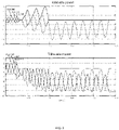
- the grid side current and the valve side current after F1 fault at the 0.02s time of the converter valve side AC connection area are shown in Fig. 2 .
- IS_A, IS_B and IS C in Fig. 2 are three-phase currents on the grid side respectively and IVC_A, IVC_B, and IVC_C are currents on the valve side.
- the phase A current and the phase B on the grid side has no zero-crossing, if only provided with the grid side switch (QF1) and without the valve side switch (QF2), the switch trip command is issued at 0.08s.
- QF1 grid side switch
- QF2 valve side switch
- the analysis found that there is a zero crossing point on the non-faulty phase valve side current.
- the valve side is added with a phase-split switch QF2.
- the valve side switch QF2 After detecting the fault in the converter station, firstly trip the non-faulty phase valve side current, since there is a zero crossing point on the non-faulty phase valve side, trip the valve side switch QF2 correspondingly, which can separate the non-faulty phase on the valve side from fault position, then the grid-side current crosses zero point, at this time, trip the grid-side switch again, and thereby fault isolation can be achieved without causing damage to the faulty switch devices.
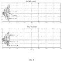
- the fault clear waveform is as shown in FIG. 3 , a fault occurs at 0.02s, and a valve side non-faulty phase trip command is issued at 0.06s.
- a grid side switch trip command is sent out with 1ms delay, and the fault is cleared within 20ms since the switch command is sent. There is no problem that the fault switch cannot be turned on and the switch is damaged and the fault cannot be cleared.
- the present invention introduces an embodiment in which the single-phase grounding fault of the converter-side AC connection region F1 or F2 is taken as an example, but the present invention is not limited to a single-phase grounding fault, and is applicable to clearing methods for other grounding faults or short-circuit faults in the converter station, for example, a bridge arm reactor is grounded and other faults.
Landscapes
- Engineering & Computer Science (AREA)
- Power Engineering (AREA)
- Physics & Mathematics (AREA)
- General Physics & Mathematics (AREA)
- Rectifiers (AREA)
- Direct Current Feeding And Distribution (AREA)
- Supply And Distribution Of Alternating Current (AREA)
- Emergency Protection Circuit Devices (AREA)
- Inverter Devices (AREA)
Description
- The present invention belongs to the field of flexible transmission and flexible alternating current (AC) transmission of power system, and particularly relates to a fault switch configuration and a clearing method in a flexible DC converter station.
- Flexible direct current (DC) transmission and a new generation of flexible AC transmission use voltage source converters, which can independently adjust active and reactive power to improve the transmission capacity of the AC system. It has obvious competitiveness in applications such as power generation grids for renewable energy, power supply for isolated islands, and interconnection of communication systems. With the development of power electronics and control technology, the capacity and voltage levels of flexible DC transmission and flexible AC transmission systems are getting higher and higher.
- In order to maintain the stability of DC voltage, flexible DC transmission requires the use of AC valve side grounding or DC side grounding to clamp DC voltage. The DC side grounding method includes a DC side monopolar grounding method, a high resistance DC side high impedance grounding, and the like. As the flexible DC transmission voltage level becomes higher and higher, a true bipolar topology is used to reduce the number of cascades of a single converter unit sub-module to achieve a large-capacity transmission power. The structure of the bipolar flexible DC transmission system usually uses the DC side grounding, and the DC side grounding causes the following problems: when the valve side and the bridge arm of the converter station are grounded or short-circuited, a loop is formed with the DC-side grounding system, and a DC bias is superimposed on the alternating current, which causes the current flowing through the grid side switch to have no zero crossing point, and thereby causes the AC switch to fail to trip, which may damage equipment such as mechanical switches and converter valves.
- Patent
CN201510999677.5 - In the past, the faulty phase selection of AC protection generally selects to firstly trip the faulty phase, but not to trip the non-faulty phase, which cannot solve the problem that there is no zero-crossing of AC current and the switch could not be broke, which is caused by the fault in the converter station brought by the DC side grounding.
- In order to achieve a reliable solution to the problem that the AC cannot be broken when an asymmetrical fault occurs in the converter station caused by the DC side grounding, to ensure the safety of the mechanical switch and the converter station equipment, to prevent the switch from failing to trip and to prevent the fault from getting worse, the present invention provides a grid side switch (QF1) and a valve side switch (QF2) which cooperates with each other in the flexible DC converter station. The grid side switch cooperates with the valve side switch, after detecting the grounding fault in the converter station, firstly trip the valve side non-faulty phase, and then trip the grid side switch by the valve side phase-split switch, and thereby the internal fault of the converter station can be quickly and effectively cleared while ensuring the safety of the AC switch.
-
- The object of the present invention is to provide a fault switch configuration and a clearing method suitable for a DC-side grounding converter station. In addition to the grid side switch (QF1), the flexible DC converter station is provided with a valve side phase-split switch (QF2). The grid side switch and the valve side switch cooperate with each other. After the protection system detects a grounding fault and a faulty phase in the converter station, firstly, the non-faulty phase on the valve side is tripped, and then the grid side switch is tripped, so that the fault in the converter station can be quickly and effectively cleared while ensuring the safety of the AC switch, and the fault in the converter station can be truly cleared, the safe operation of the converter station equipment can be ensured, and prevent the influence of the fault from expanding.
- In order to achieve the above object, the solutions of the present invention are described as below:
- A fault clearing method in a flexible DC converter station is defined in the appended
independent claim 1, wherein a flexible DC converter station respectively configured with a grid side switch (QF1) and a valve side switch (QF2), and when a fault occurs in the converter station, firstly tripping a valve side non-faulty phase switch, then tripping the grid side switch, and performing the clearing for faults in the converter station, the clearing method for the faults specifically includes: - 1) recognizing, by a protection system, a faulty phase and a non-faulty phase when a fault is detected in the converter station;
- 2) sending a non-faulty phase valve side switch (QF2) trip command at time t1;
- 3) sending a grid side switch (QF1) trip command at time t2;
- 4) the relationship between t1 and t2 is t1<t2.
- 5) sending a faulty phase valve side switch (QF2) trip command after a time interval Δt, after tripping the grid side switch (QF1).
- According to the fault clearing method in a flexible DC converter station, further the protection system may use a differential protection detection to obtain a faulty phase or a valve side low voltage overcurrent to determine a fault location and a faulty phase.
- According to the fault clearing method in a flexible DC converter station, further the value of t1 ranges from 0 to 10s, the value of t2 ranges from 0 to 15s, and the time interval Δ t is greater than 0.
- According to the fault clearing method in a flexible DC converter station, the configured valve side switch (QF2) is a phase-split switch.
- According to the fault clearing method in a flexible DC converter station, the fault region in the converter station mainly refers to a fault between a synchronous voltage Us and the positive bus bar and the negative bus bar.
- A fault switch configuration in a flexible DC converter station is defined in the appended
independent claim 6 and is adapted to perform the fault clearing method, the fault switch configuration comprising: a transformer which is used for station power supply; a converter valve which includes grounding achieved by closing a grounding switch QS5; a control and protection system which can rely on the differential current (IVT-IVC); and a grid side switch (QF1) and a valve side switch (QF2) as being connected together. -
-
Fig. 1 is a schematic view of switch positions and faulty locations in a faulty converter station according to the present invention. -
Fig. 2 is a waveform diagram of the fault current in the case where only the grid side switch is tripped when a valve side failure occurs. -
Fig. 3 is a waveform diagram of the fault current in the case where the grid side switch and the valve side switch are tripped in cooperation with each other when a valve side failure occurs. - The technical solutions of the present invention will be described in detail below with reference to the accompanying drawings and specific embodiments.
- The invention studies faults in a converter station of a DC side grounding system and provides a switch configuration and a clearing method. The grounding of a converter valve can be achieved by closing a grounding switch QS5 in
Fig. 1 . - Generally, the flexible DC transmission converter station is equipped with a grid side switch (QF1) and without a valve side switch (QF2). Unless some converter stations with three-winding transformers are equipped with valve-side switches (QF2), the third winding of the transformer is used for station power supply. The purpose of configuring the valve-side switch (QF2) is to enable the operation of the transformer during maintenance of the converter valve.
-
Fig. 1 : grid side synchronous voltage Us, grid side current IS, grid side switch QF1, valve side phase-split switch QF2, transformer valve side bushing current IVT, bypass switch QF3, valve side voltage UV, valve side current IVC, DC bus current IDP, neutral bus current IDNC. - Taking grounding faults of C-phase positions F1 or F2 of the
converter valve pole 1 as an example, the grid side current and the valve side current after F1 fault at the 0.02s time of the converter valve side AC connection area are shown inFig. 2 . IS_A, IS_B and IS C inFig. 2 are three-phase currents on the grid side respectively and IVC_A, IVC_B, and IVC_C are currents on the valve side. As shown inFig. 2 , the phase A current and the phase B on the grid side has no zero-crossing, if only provided with the grid side switch (QF1) and without the valve side switch (QF2), the switch trip command is issued at 0.08s. As shown inFig. 2 , since the B phase current has no zero-crossing, it needs about 140ms after the switch trip command is sent to turn on the grid side switch, and in this process, since there is no zero-crossing point to forcibly turn off the switch QF1, the switch contacts and the like are damaged, and the fault cannot be effectively cleared. - For the valve side fault in the converter station, the analysis found that there is a zero crossing point on the non-faulty phase valve side current. Through a series of calculations and analysis, the valve side is added with a phase-split switch QF2. After detecting the fault in the converter station, firstly trip the non-faulty phase valve side current, since there is a zero crossing point on the non-faulty phase valve side, trip the valve side switch QF2 correspondingly, which can separate the non-faulty phase on the valve side from fault position, then the grid-side current crosses zero point, at this time, trip the grid-side switch again, and thereby fault isolation can be achieved without causing damage to the faulty switch devices.
- Specific steps are as follows:
- 1. In addition to the grid side switch (QF1), the flexible DC converter station is configured with a valve side phase-split switch (QF2).
- 2. A control and protection system in the converter station can rely on the differential current (IVT-IVC) between IVT and IVC to be greater than the set value Idelt. Idelt takes the rated value of 1.0 pu. It is considered that if the fault position is on the valve side of the converter station, it is a faulty phase. Otherwise, it is a non-faulty phase.
- 3. After detecting and identifying the fault position and the faulty phase, the converter valve control protection system delays time t1 to send a non-faulty phase trip command to the valve side switch (QF2), and t1 is set within (0-10s).
- 4. The control and protection system in the converter station delays time t2 to send to the grid side switch QF1, and t2 is set within (0-15s).
- 5. The relationship between t1 and t2 is t1<t2.
- 6. After the grid side switch is tripped, delay time Δt to send the faulty phase trip command to the valve side switch (QF2), and Δt is greater than 0.
- 7. After the above steps, the three-phase QF1 and QF2 switches are tripped, and the fault is cleared without damaging the switch.
- According to the fault switch configuration and clearing method in a flexible DC converter station of the present invention, after a valve side grounding fault occurs, the fault clear waveform is as shown in
FIG. 3 , a fault occurs at 0.02s, and a valve side non-faulty phase trip command is issued at 0.06s. A grid side switch trip command is sent out with 1ms delay, and the fault is cleared within 20ms since the switch command is sent. There is no problem that the fault switch cannot be turned on and the switch is damaged and the fault cannot be cleared. - The present invention introduces an embodiment in which the single-phase grounding fault of the converter-side AC connection region F1 or F2 is taken as an example, but the present invention is not limited to a single-phase grounding fault, and is applicable to clearing methods for other grounding faults or short-circuit faults in the converter station, for example, a bridge arm reactor is grounded and other faults.
- The foregoing embodiments are used to explain the technical idea of the present invention, but are not intended to limit the scope of protection of the preset invention.
Claims (6)
- A fault clearing method in a flexible DC converter station comprising a flexible DC converter station respectively configured with a grid side switch (QF1) and a valve side phase-split switch (QF2), and when a fault occurs in the converter station, firstly tripping a valve side non-faulty phase switch, then tripping the grid side switch, and performing the clearing for faults in the converter station, the clearing method is characterised in that it includes:recognizing, by a protection system, a faulty phase and a non-faulty phase when a fault occurs in the converter station;sending a non-faulty phase valve side switch (QF2) trip command at time t1, and sending a grid side switch (QF1) trip command at time t2, wherein the relationship between t1 and t2 is t1<t2;sending a faulty phase valve side switch (QF2) trip command after a time interval Δt, after tripping the grid side switch (QF1).
- The fault clearing method in a flexible DC converter station according to claim 1, characterized in that the faulty phase is detected by using differential protection, or the faulty phase is determined according to a low voltage overcurrent of the valve side.
- The fault clearing method in a flexible DC converter station according to claim 1, wherein the value of t1 ranges from 0 to 10s, the value of t2 ranges from 0 to 15s, and the time interval Δt is greater than 0.
- The fault clearing method in a flexible DC converter station according to claim 1, wherein the valve side switch (QF2) uses a phase-split switch.
- The fault clearing method in the flexible DC converter station according to claim 1, wherein a fault in the converter station is a fault in a region between the secondary side of a transformer, a pole bus and a neutral bus.
- A fault switch configuration in a flexible DC converter station, comprising:a transformer which is used for a station power supply;a converter valve which includes grounding achieved by closing a grounding switch QS5;a protection system;a grid side switch (QF1) connected between the electrical grid and the transformer;and a valve side phase-split switch (QF2) connected between the transformer and the converter valve,the fault switching configuration is characterised in being adapted to perform the fault clearing method according to any of the preceding claims.
Applications Claiming Priority (2)
| Application Number | Priority Date | Filing Date | Title |
|---|---|---|---|
| CN201710406486.2A CN107093890B (en) | 2017-06-02 | 2017-06-02 | Fault switch configuration and clearing method in a flexible DC converter station |
| PCT/CN2018/087791 WO2018219174A1 (en) | 2017-06-02 | 2018-05-22 | Fault switch configuration and clearing method in flexible dc converter station |
Publications (3)
| Publication Number | Publication Date |
|---|---|
| EP3595116A1 EP3595116A1 (en) | 2020-01-15 |
| EP3595116A4 EP3595116A4 (en) | 2020-12-16 |
| EP3595116B1 true EP3595116B1 (en) | 2022-10-05 |
Family
ID=59639021
Family Applications (1)
| Application Number | Title | Priority Date | Filing Date |
|---|---|---|---|
| EP18809522.8A Active EP3595116B1 (en) | 2017-06-02 | 2018-05-22 | Fault switch configuration and clearing method in flexible dc converter station |
Country Status (10)
| Country | Link |
|---|---|
| US (1) | US10923906B2 (en) |
| EP (1) | EP3595116B1 (en) |
| JP (1) | JP6784850B2 (en) |
| KR (1) | KR102124287B1 (en) |
| CN (1) | CN107093890B (en) |
| CA (1) | CA3060024C (en) |
| DK (1) | DK3595116T3 (en) |
| MX (1) | MX2019013245A (en) |
| RU (1) | RU2718619C1 (en) |
| WO (1) | WO2018219174A1 (en) |
Families Citing this family (22)
| Publication number | Priority date | Publication date | Assignee | Title |
|---|---|---|---|---|
| CN107093890B (en) | 2017-06-02 | 2019-03-08 | 南京南瑞继保电气有限公司 | Fault switch configuration and clearing method in a flexible DC converter station |
| CN109672150A (en) * | 2017-10-13 | 2019-04-23 | 贵州电网有限责任公司电力调度控制中心 | Sweep-out method and device suitable for bipolar DC system converter valve side exchanging area failure |
| CN110672972B (en) * | 2019-09-09 | 2021-05-04 | 华北电力大学 | A fault location and isolation method for flexible DC distribution network |
| CN111276942B (en) * | 2020-03-26 | 2022-05-10 | 特变电工西安柔性输配电有限公司 | Bridge arm current stress reduction method for offshore wind power flexible direct-transmission system |
| CN113949042B (en) * | 2020-07-17 | 2024-07-30 | 中国南方电网有限责任公司超高压输电公司 | A method for isolating a UHV DC valve group and a faulty valve group |
| CN112054490B (en) * | 2020-08-11 | 2022-12-06 | 南方电网科学研究院有限责任公司 | Method and device for third station failure exit under multi-terminal DC unipolar metal operation mode |
| CN111934285B (en) * | 2020-09-10 | 2024-07-23 | 桂林五环电器制造有限公司 | Method and device for protecting turn-to-turn short circuit of dry type air-core reactor |
| CN113765056B (en) * | 2020-12-12 | 2022-09-02 | 保定钰鑫电气科技有限公司 | Single-phase grounding processing method |
| CN112701655B (en) * | 2020-12-23 | 2024-10-29 | 上海科梁信息科技股份有限公司 | Reclosing and starting control method, reclosing and starting control equipment and storage medium in direct-current transmission system |
| CN112838610B (en) * | 2021-01-17 | 2023-12-15 | 昆明理工大学 | A ground fault analysis method of MMC converter station based on two-port network considering neutral point current |
| CN112886556B (en) * | 2021-03-04 | 2022-12-16 | 中国南方电网有限责任公司 | Single-phase earth fault control protection method for flexible direct current transmission alternating current connection line area |
| CN113013860B (en) * | 2021-03-29 | 2024-02-06 | 西安西电电力系统有限公司 | Converter valve overvoltage suppression method and device |
| CN113988648B (en) * | 2021-10-29 | 2024-11-26 | 广东电网有限责任公司 | A method and device for calculating risk value of wind power flexible direct current system |
| CN114362230B (en) * | 2021-12-09 | 2024-05-07 | 南方电网科学研究院有限责任公司 | Multi-transformer parallel flexible DC converter station with shared grounding device and switching method thereof |
| CN114552546B (en) * | 2022-03-04 | 2023-08-15 | 广东电网有限责任公司广州供电局 | Cross-station tripping method, system, equipment and medium applied to flexible direct current transmission system |
| CN114759533B (en) * | 2022-05-06 | 2025-05-16 | 中国矿业大学(北京) | Correction-type line differential protection method for flexible DC transmission system |
| CN115133502B (en) * | 2022-06-22 | 2023-09-29 | 上海勘测设计研究院有限公司 | A method for removing AC bus faults in energy storage power stations |
| CN115425625B (en) * | 2022-08-25 | 2025-04-29 | 天津大学 | A hybrid cascade multi-terminal DC transmission line protection method based on current correlation coefficient |
| CN117574587B (en) * | 2023-11-22 | 2025-04-08 | 南方电网科学研究院有限责任公司 | Method and device for evaluating grounding clamp position of metal return line in flexible DC transmission system |
| CN119010159B (en) * | 2024-10-24 | 2025-02-28 | 国网浙江省电力有限公司电力科学研究院 | A control and protection system for a flexible DC transmission system adapted to the flexible access of converter stations |
| CN119154238A (en) * | 2024-11-13 | 2024-12-17 | 中国能源建设集团广东省电力设计研究院有限公司 | DC converter station protection method and system based on AC section power loss |
| CN120222498B (en) * | 2025-03-19 | 2026-04-28 | 湖南大学 | A multi-objective cooperative network converter fault ride-through method, apparatus, electronic equipment, and storage medium |
Family Cites Families (15)
| Publication number | Priority date | Publication date | Assignee | Title |
|---|---|---|---|---|
| JP4108614B2 (en) * | 2004-01-13 | 2008-06-25 | 三菱電機株式会社 | Phase control switchgear |
| US8098504B2 (en) * | 2006-01-18 | 2012-01-17 | Abb Technology Ltd. | Converter station for connecting an AC system to an end of an HVDC transmission line |
| RU2414720C2 (en) * | 2009-03-10 | 2011-03-20 | Ооо "Нииэфа-Энерго" | Control and protection device of alternating current connections of system of traction electric power supply, and control system of traction substation by using control and protection devices of alternating current connections |
| JP5378274B2 (en) * | 2010-03-15 | 2013-12-25 | 株式会社日立製作所 | Power converter |
| US8767422B2 (en) * | 2010-06-01 | 2014-07-01 | Abb Technology Ag | Interface arrangement between AC and DC systems using grounding switch |
| WO2011150962A1 (en) * | 2010-06-01 | 2011-12-08 | Abb Technology Ag | Interface arrangement between ac and dc systems including filter at transformer neutral point |
| JP6018934B2 (en) * | 2013-01-25 | 2016-11-02 | 株式会社日立製作所 | Power converter |
| CN103606911B (en) * | 2013-10-12 | 2016-05-25 | 张家港智能电力研究院有限公司 | A Method for Cutting Instantaneous Short-Circuit Grounding Faults of DC Lines in Flexible DC Transmission System |
| CN103986176B (en) * | 2014-04-01 | 2016-09-21 | 南方电网科学研究院有限责任公司 | A method for live-connecting a converter station into a multi-terminal flexible direct current transmission system |
| JP5730458B1 (en) * | 2014-10-08 | 2015-06-10 | 三菱電機株式会社 | Power converter |
| EP3213399B1 (en) * | 2014-10-30 | 2020-12-30 | ABB Power Grids Switzerland AG | Method in, apparatus for, and interface arrangement between an alternating current power system and a direct current power system |
| CN105703336B (en) * | 2015-12-28 | 2019-03-08 | 国网辽宁省电力有限公司电力科学研究院 | Single-phase grounding fault control and protection method in bipolar flexible HVDC transmission system |
| CN105703481B (en) * | 2016-03-03 | 2018-03-30 | 南京南瑞继保电气有限公司 | A kind of equal pressure condition uniformity statistical method of converter valve |
| CN105790238B (en) * | 2016-04-27 | 2019-02-15 | 南方电网科学研究院有限责任公司 | A bipolar MMC-HVDC power transmission system and protection method for valve side single-phase ground fault |
| CN107093890B (en) * | 2017-06-02 | 2019-03-08 | 南京南瑞继保电气有限公司 | Fault switch configuration and clearing method in a flexible DC converter station |
-
2017
- 2017-06-02 CN CN201710406486.2A patent/CN107093890B/en active Active
-
2018
- 2018-05-22 MX MX2019013245A patent/MX2019013245A/en unknown
- 2018-05-22 US US16/500,189 patent/US10923906B2/en not_active Expired - Fee Related
- 2018-05-22 CA CA3060024A patent/CA3060024C/en active Active
- 2018-05-22 EP EP18809522.8A patent/EP3595116B1/en active Active
- 2018-05-22 WO PCT/CN2018/087791 patent/WO2018219174A1/en not_active Ceased
- 2018-05-22 DK DK18809522.8T patent/DK3595116T3/en active
- 2018-05-22 RU RU2019136268A patent/RU2718619C1/en active
- 2018-05-22 KR KR1020197026158A patent/KR102124287B1/en active Active
- 2018-05-22 JP JP2019551432A patent/JP6784850B2/en active Active
Also Published As
| Publication number | Publication date |
|---|---|
| CA3060024A1 (en) | 2018-12-06 |
| BR112019024168A2 (en) | 2020-06-02 |
| KR102124287B1 (en) | 2020-06-17 |
| KR20190107173A (en) | 2019-09-18 |
| CA3060024C (en) | 2020-08-25 |
| US10923906B2 (en) | 2021-02-16 |
| WO2018219174A1 (en) | 2018-12-06 |
| CN107093890B (en) | 2019-03-08 |
| MX2019013245A (en) | 2020-01-27 |
| JP6784850B2 (en) | 2020-11-11 |
| DK3595116T3 (en) | 2023-01-09 |
| US20200220349A1 (en) | 2020-07-09 |
| EP3595116A4 (en) | 2020-12-16 |
| JP2020520210A (en) | 2020-07-02 |
| CN107093890A (en) | 2017-08-25 |
| RU2718619C1 (en) | 2020-04-09 |
| EP3595116A1 (en) | 2020-01-15 |
Similar Documents
| Publication | Publication Date | Title |
|---|---|---|
| EP3595116B1 (en) | Fault switch configuration and clearing method in flexible dc converter station | |
| CN105048488B (en) | A kind of flexible direct current network DC short trouble traversing method | |
| Zheng et al. | An integrated control and protection scheme based on FBSM-MMC active current limiting strategy for DC distribution network | |
| CN111224569B (en) | A low full-bridge ratio sub-module hybrid MMC and its DC fault handling strategy | |
| CN103490392B (en) | Fault handling method of power distribution network comprising distributed power supplies and microgrids | |
| CN106655237A (en) | Direct current monopole grounding fault ride-through method for multi-port flexible high-voltage direct current power transmission system | |
| CN109659967A (en) | Converter station containing resistive superconducting current limiter and dc circuit breaker and its DC Line Fault processing strategie | |
| CN109617026B (en) | An ultra-high-speed protection method for ground fault of DC grid converter station | |
| CN102818972A (en) | Microgrid failure locating method | |
| CN107863762A (en) | A kind of direct current network earth fault ultrahigh speed Non-unit protection method | |
| CN106026048A (en) | DC grid fault handling strategy based on in-situ detection and in -situ protection | |
| CN114123137A (en) | Intelligent dynamic resistance grounding and arc suppression coil grounding parallel fault processing method | |
| CN105790238A (en) | A bipolar MMC-HVDC power transmission system and a protection method for single-phase ground faults on the valve side | |
| CN107565521B (en) | A method for clearing the DC side short-circuit fault of a flexible DC power grid | |
| CN115453265A (en) | A Fault Transient Protection Method for Island Microgrid Based on Current Waveform Characteristics of Initial Fault | |
| CN113595040A (en) | Annular direct-current micro-grid single-ended current type distance measurement method based on control and protection cooperation | |
| Rahman et al. | DC fault protection of multi-terminal HVDC systems using DC network partition and DC circuit breakers | |
| CN111682510A (en) | First cut and then isolation protection method for ground fault in symmetrical unipolar DC microgrid | |
| Li et al. | Study on Fault Control Requirement and Strategy of Large Scale Renewable Energy VSC-HVDC Integration | |
| CN114825304A (en) | LCC-FHMMC converter valve outlet alternating current single-phase earth fault characteristic analysis and protection method | |
| CN210744758U (en) | A Multi-terminal HVDC Transmission System Based on Superconducting Current Limiter | |
| Cao et al. | Multi-terminal hybrid UHVDC line protection scheme | |
| CN110535105B (en) | A fault isolation method for DC microgrid based on AC circuit breaker removal | |
| Zheng et al. | Inter-pole short circuit protection strategy for flexible DC distribution network converter valve and differential combination | |
| Jin et al. | A Non-Pilot Protection Scheme for Transmission Lines Connected to Inverter-Interfaced Power Source |
Legal Events
| Date | Code | Title | Description |
|---|---|---|---|
| STAA | Information on the status of an ep patent application or granted ep patent |
Free format text: STATUS: THE INTERNATIONAL PUBLICATION HAS BEEN MADE |
|
| PUAI | Public reference made under article 153(3) epc to a published international application that has entered the european phase |
Free format text: ORIGINAL CODE: 0009012 |
|
| STAA | Information on the status of an ep patent application or granted ep patent |
Free format text: STATUS: REQUEST FOR EXAMINATION WAS MADE |
|
| 17P | Request for examination filed |
Effective date: 20191011 |
|
| AK | Designated contracting states |
Kind code of ref document: A1 Designated state(s): AL AT BE BG CH CY CZ DE DK EE ES FI FR GB GR HR HU IE IS IT LI LT LU LV MC MK MT NL NO PL PT RO RS SE SI SK SM TR |
|
| AX | Request for extension of the european patent |
Extension state: BA ME |
|
| RIN1 | Information on inventor provided before grant (corrected) |
Inventor name: LI, HAIYING Inventor name: SUI, SHUNKE Inventor name: LI, GANG Inventor name: WANG, NANNAN Inventor name: LU, YU Inventor name: TIAN, JIE Inventor name: JIANG, CHONGXUE |
|
| DAV | Request for validation of the european patent (deleted) | ||
| DAX | Request for extension of the european patent (deleted) | ||
| A4 | Supplementary search report drawn up and despatched |
Effective date: 20201117 |
|
| RIC1 | Information provided on ipc code assigned before grant |
Ipc: H02J 3/36 20060101ALI20201111BHEP Ipc: H02H 7/125 20060101ALI20201111BHEP Ipc: H02H 3/16 20060101ALI20201111BHEP Ipc: H02H 7/26 20060101AFI20201111BHEP |
|
| GRAP | Despatch of communication of intention to grant a patent |
Free format text: ORIGINAL CODE: EPIDOSNIGR1 |
|
| STAA | Information on the status of an ep patent application or granted ep patent |
Free format text: STATUS: GRANT OF PATENT IS INTENDED |
|
| INTG | Intention to grant announced |
Effective date: 20220610 |
|
| RIN1 | Information on inventor provided before grant (corrected) |
Inventor name: SUI, SHUNKE Inventor name: JIANG, CHONGXUE Inventor name: LI, HAIYING Inventor name: WANG, NANNAN Inventor name: TIAN, JIE Inventor name: LI, GANG Inventor name: LU, YU |
|
| GRAS | Grant fee paid |
Free format text: ORIGINAL CODE: EPIDOSNIGR3 |
|
| GRAA | (expected) grant |
Free format text: ORIGINAL CODE: 0009210 |
|
| STAA | Information on the status of an ep patent application or granted ep patent |
Free format text: STATUS: THE PATENT HAS BEEN GRANTED |
|
| AK | Designated contracting states |
Kind code of ref document: B1 Designated state(s): AL AT BE BG CH CY CZ DE DK EE ES FI FR GB GR HR HU IE IS IT LI LT LU LV MC MK MT NL NO PL PT RO RS SE SI SK SM TR |
|
| REG | Reference to a national code |
Ref country code: GB Ref legal event code: FG4D |
|
| REG | Reference to a national code |
Ref country code: CH Ref legal event code: EP |
|
| REG | Reference to a national code |
Ref country code: AT Ref legal event code: REF Ref document number: 1523363 Country of ref document: AT Kind code of ref document: T Effective date: 20221015 |
|
| REG | Reference to a national code |
Ref country code: IE Ref legal event code: FG4D |
|
| REG | Reference to a national code |
Ref country code: DE Ref legal event code: R096 Ref document number: 602018041476 Country of ref document: DE |
|
| REG | Reference to a national code |
Ref country code: DK Ref legal event code: T3 Effective date: 20230103 |
|
| REG | Reference to a national code |
Ref country code: LT Ref legal event code: MG9D |
|
| REG | Reference to a national code |
Ref country code: NL Ref legal event code: MP Effective date: 20221005 |
|
| REG | Reference to a national code |
Ref country code: AT Ref legal event code: MK05 Ref document number: 1523363 Country of ref document: AT Kind code of ref document: T Effective date: 20221005 |
|
| REG | Reference to a national code |
Ref country code: GR Ref legal event code: EP Ref document number: 20230400003 Country of ref document: GR Effective date: 20230210 |
|
| PG25 | Lapsed in a contracting state [announced via postgrant information from national office to epo] |
Ref country code: NL Free format text: LAPSE BECAUSE OF FAILURE TO SUBMIT A TRANSLATION OF THE DESCRIPTION OR TO PAY THE FEE WITHIN THE PRESCRIBED TIME-LIMIT Effective date: 20221005 |
|
| PG25 | Lapsed in a contracting state [announced via postgrant information from national office to epo] |
Ref country code: SE Free format text: LAPSE BECAUSE OF FAILURE TO SUBMIT A TRANSLATION OF THE DESCRIPTION OR TO PAY THE FEE WITHIN THE PRESCRIBED TIME-LIMIT Effective date: 20221005 Ref country code: PT Free format text: LAPSE BECAUSE OF FAILURE TO SUBMIT A TRANSLATION OF THE DESCRIPTION OR TO PAY THE FEE WITHIN THE PRESCRIBED TIME-LIMIT Effective date: 20230206 Ref country code: NO Free format text: LAPSE BECAUSE OF FAILURE TO SUBMIT A TRANSLATION OF THE DESCRIPTION OR TO PAY THE FEE WITHIN THE PRESCRIBED TIME-LIMIT Effective date: 20230105 Ref country code: LT Free format text: LAPSE BECAUSE OF FAILURE TO SUBMIT A TRANSLATION OF THE DESCRIPTION OR TO PAY THE FEE WITHIN THE PRESCRIBED TIME-LIMIT Effective date: 20221005 Ref country code: FI Free format text: LAPSE BECAUSE OF FAILURE TO SUBMIT A TRANSLATION OF THE DESCRIPTION OR TO PAY THE FEE WITHIN THE PRESCRIBED TIME-LIMIT Effective date: 20221005 Ref country code: ES Free format text: LAPSE BECAUSE OF FAILURE TO SUBMIT A TRANSLATION OF THE DESCRIPTION OR TO PAY THE FEE WITHIN THE PRESCRIBED TIME-LIMIT Effective date: 20221005 Ref country code: AT Free format text: LAPSE BECAUSE OF FAILURE TO SUBMIT A TRANSLATION OF THE DESCRIPTION OR TO PAY THE FEE WITHIN THE PRESCRIBED TIME-LIMIT Effective date: 20221005 |
|
| PG25 | Lapsed in a contracting state [announced via postgrant information from national office to epo] |
Ref country code: RS Free format text: LAPSE BECAUSE OF FAILURE TO SUBMIT A TRANSLATION OF THE DESCRIPTION OR TO PAY THE FEE WITHIN THE PRESCRIBED TIME-LIMIT Effective date: 20221005 Ref country code: PL Free format text: LAPSE BECAUSE OF FAILURE TO SUBMIT A TRANSLATION OF THE DESCRIPTION OR TO PAY THE FEE WITHIN THE PRESCRIBED TIME-LIMIT Effective date: 20221005 Ref country code: LV Free format text: LAPSE BECAUSE OF FAILURE TO SUBMIT A TRANSLATION OF THE DESCRIPTION OR TO PAY THE FEE WITHIN THE PRESCRIBED TIME-LIMIT Effective date: 20221005 Ref country code: IS Free format text: LAPSE BECAUSE OF FAILURE TO SUBMIT A TRANSLATION OF THE DESCRIPTION OR TO PAY THE FEE WITHIN THE PRESCRIBED TIME-LIMIT Effective date: 20230205 Ref country code: HR Free format text: LAPSE BECAUSE OF FAILURE TO SUBMIT A TRANSLATION OF THE DESCRIPTION OR TO PAY THE FEE WITHIN THE PRESCRIBED TIME-LIMIT Effective date: 20221005 |
|
| REG | Reference to a national code |
Ref country code: DE Ref legal event code: R097 Ref document number: 602018041476 Country of ref document: DE |
|
| PG25 | Lapsed in a contracting state [announced via postgrant information from national office to epo] |
Ref country code: SM Free format text: LAPSE BECAUSE OF FAILURE TO SUBMIT A TRANSLATION OF THE DESCRIPTION OR TO PAY THE FEE WITHIN THE PRESCRIBED TIME-LIMIT Effective date: 20221005 Ref country code: RO Free format text: LAPSE BECAUSE OF FAILURE TO SUBMIT A TRANSLATION OF THE DESCRIPTION OR TO PAY THE FEE WITHIN THE PRESCRIBED TIME-LIMIT Effective date: 20221005 Ref country code: EE Free format text: LAPSE BECAUSE OF FAILURE TO SUBMIT A TRANSLATION OF THE DESCRIPTION OR TO PAY THE FEE WITHIN THE PRESCRIBED TIME-LIMIT Effective date: 20221005 Ref country code: CZ Free format text: LAPSE BECAUSE OF FAILURE TO SUBMIT A TRANSLATION OF THE DESCRIPTION OR TO PAY THE FEE WITHIN THE PRESCRIBED TIME-LIMIT Effective date: 20221005 |
|
| PLBE | No opposition filed within time limit |
Free format text: ORIGINAL CODE: 0009261 |
|
| STAA | Information on the status of an ep patent application or granted ep patent |
Free format text: STATUS: NO OPPOSITION FILED WITHIN TIME LIMIT |
|
| PG25 | Lapsed in a contracting state [announced via postgrant information from national office to epo] |
Ref country code: SK Free format text: LAPSE BECAUSE OF FAILURE TO SUBMIT A TRANSLATION OF THE DESCRIPTION OR TO PAY THE FEE WITHIN THE PRESCRIBED TIME-LIMIT Effective date: 20221005 Ref country code: AL Free format text: LAPSE BECAUSE OF FAILURE TO SUBMIT A TRANSLATION OF THE DESCRIPTION OR TO PAY THE FEE WITHIN THE PRESCRIBED TIME-LIMIT Effective date: 20221005 |
|
| 26N | No opposition filed |
Effective date: 20230706 |
|
| PG25 | Lapsed in a contracting state [announced via postgrant information from national office to epo] |
Ref country code: SI Free format text: LAPSE BECAUSE OF FAILURE TO SUBMIT A TRANSLATION OF THE DESCRIPTION OR TO PAY THE FEE WITHIN THE PRESCRIBED TIME-LIMIT Effective date: 20221005 |
|
| REG | Reference to a national code |
Ref country code: CH Ref legal event code: PL |
|
| PG25 | Lapsed in a contracting state [announced via postgrant information from national office to epo] |
Ref country code: MC Free format text: LAPSE BECAUSE OF FAILURE TO SUBMIT A TRANSLATION OF THE DESCRIPTION OR TO PAY THE FEE WITHIN THE PRESCRIBED TIME-LIMIT Effective date: 20221005 |
|
| REG | Reference to a national code |
Ref country code: BE Ref legal event code: MM Effective date: 20230531 |
|
| PG25 | Lapsed in a contracting state [announced via postgrant information from national office to epo] |
Ref country code: MC Free format text: LAPSE BECAUSE OF FAILURE TO SUBMIT A TRANSLATION OF THE DESCRIPTION OR TO PAY THE FEE WITHIN THE PRESCRIBED TIME-LIMIT Effective date: 20221005 Ref country code: LU Free format text: LAPSE BECAUSE OF NON-PAYMENT OF DUE FEES Effective date: 20230522 Ref country code: LI Free format text: LAPSE BECAUSE OF NON-PAYMENT OF DUE FEES Effective date: 20230531 Ref country code: CH Free format text: LAPSE BECAUSE OF NON-PAYMENT OF DUE FEES Effective date: 20230531 |
|
| REG | Reference to a national code |
Ref country code: IE Ref legal event code: MM4A |
|
| PG25 | Lapsed in a contracting state [announced via postgrant information from national office to epo] |
Ref country code: IE Free format text: LAPSE BECAUSE OF NON-PAYMENT OF DUE FEES Effective date: 20230522 |
|
| PG25 | Lapsed in a contracting state [announced via postgrant information from national office to epo] |
Ref country code: IE Free format text: LAPSE BECAUSE OF NON-PAYMENT OF DUE FEES Effective date: 20230522 |
|
| PG25 | Lapsed in a contracting state [announced via postgrant information from national office to epo] |
Ref country code: IT Free format text: LAPSE BECAUSE OF FAILURE TO SUBMIT A TRANSLATION OF THE DESCRIPTION OR TO PAY THE FEE WITHIN THE PRESCRIBED TIME-LIMIT Effective date: 20221005 Ref country code: BE Free format text: LAPSE BECAUSE OF NON-PAYMENT OF DUE FEES Effective date: 20230531 |
|
| PG25 | Lapsed in a contracting state [announced via postgrant information from national office to epo] |
Ref country code: BG Free format text: LAPSE BECAUSE OF FAILURE TO SUBMIT A TRANSLATION OF THE DESCRIPTION OR TO PAY THE FEE WITHIN THE PRESCRIBED TIME-LIMIT Effective date: 20221005 |
|
| PG25 | Lapsed in a contracting state [announced via postgrant information from national office to epo] |
Ref country code: BG Free format text: LAPSE BECAUSE OF FAILURE TO SUBMIT A TRANSLATION OF THE DESCRIPTION OR TO PAY THE FEE WITHIN THE PRESCRIBED TIME-LIMIT Effective date: 20221005 |
|
| PGFP | Annual fee paid to national office [announced via postgrant information from national office to epo] |
Ref country code: DE Payment date: 20250513 Year of fee payment: 8 |
|
| PGFP | Annual fee paid to national office [announced via postgrant information from national office to epo] |
Ref country code: DK Payment date: 20250428 Year of fee payment: 8 Ref country code: GB Payment date: 20250521 Year of fee payment: 8 |
|
| PGFP | Annual fee paid to national office [announced via postgrant information from national office to epo] |
Ref country code: FR Payment date: 20250530 Year of fee payment: 8 |
|
| PGFP | Annual fee paid to national office [announced via postgrant information from national office to epo] |
Ref country code: GR Payment date: 20250423 Year of fee payment: 8 |
|
| PG25 | Lapsed in a contracting state [announced via postgrant information from national office to epo] |
Ref country code: CY Free format text: LAPSE BECAUSE OF FAILURE TO SUBMIT A TRANSLATION OF THE DESCRIPTION OR TO PAY THE FEE WITHIN THE PRESCRIBED TIME-LIMIT; INVALID AB INITIO Effective date: 20180522 |
|
| PG25 | Lapsed in a contracting state [announced via postgrant information from national office to epo] |
Ref country code: HU Free format text: LAPSE BECAUSE OF FAILURE TO SUBMIT A TRANSLATION OF THE DESCRIPTION OR TO PAY THE FEE WITHIN THE PRESCRIBED TIME-LIMIT; INVALID AB INITIO Effective date: 20180522 |
|
| PG25 | Lapsed in a contracting state [announced via postgrant information from national office to epo] |
Ref country code: TR Free format text: LAPSE BECAUSE OF FAILURE TO SUBMIT A TRANSLATION OF THE DESCRIPTION OR TO PAY THE FEE WITHIN THE PRESCRIBED TIME-LIMIT Effective date: 20221005 |