EP3595080B1 - Cooler - Google Patents
Cooler Download PDFInfo
- Publication number
- EP3595080B1 EP3595080B1 EP19187111.0A EP19187111A EP3595080B1 EP 3595080 B1 EP3595080 B1 EP 3595080B1 EP 19187111 A EP19187111 A EP 19187111A EP 3595080 B1 EP3595080 B1 EP 3595080B1
- Authority
- EP
- European Patent Office
- Prior art keywords
- lid member
- upper lid
- cooling plate
- side walls
- refrigerant
- Prior art date
- Legal status (The legal status is an assumption and is not a legal conclusion. Google has not performed a legal analysis and makes no representation as to the accuracy of the status listed.)
- Active
Links
Images








Classifications
-
- F—MECHANICAL ENGINEERING; LIGHTING; HEATING; WEAPONS; BLASTING
- F28—HEAT EXCHANGE IN GENERAL
- F28F—DETAILS OF HEAT-EXCHANGE AND HEAT-TRANSFER APPARATUS, OF GENERAL APPLICATION
- F28F9/00—Casings; Header boxes; Auxiliary supports for elements; Auxiliary members within casings
- F28F9/02—Header boxes; End plates
- F28F9/0246—Arrangements for connecting header boxes with flow lines
- F28F9/0251—Massive connectors, e.g. blocks; Plate-like connectors
-
- F—MECHANICAL ENGINEERING; LIGHTING; HEATING; WEAPONS; BLASTING
- F28—HEAT EXCHANGE IN GENERAL
- F28F—DETAILS OF HEAT-EXCHANGE AND HEAT-TRANSFER APPARATUS, OF GENERAL APPLICATION
- F28F9/00—Casings; Header boxes; Auxiliary supports for elements; Auxiliary members within casings
- F28F9/02—Header boxes; End plates
- F28F9/04—Arrangements for sealing elements into header boxes or end plates
- F28F9/16—Arrangements for sealing elements into header boxes or end plates by permanent joints, e.g. by rolling
- F28F9/18—Arrangements for sealing elements into header boxes or end plates by permanent joints, e.g. by rolling by welding
-
- H—ELECTRICITY
- H01—ELECTRIC ELEMENTS
- H01M—PROCESSES OR MEANS, e.g. BATTERIES, FOR THE DIRECT CONVERSION OF CHEMICAL ENERGY INTO ELECTRICAL ENERGY
- H01M10/00—Secondary cells; Manufacture thereof
- H01M10/60—Heating or cooling; Temperature control
- H01M10/61—Types of temperature control
- H01M10/613—Cooling or keeping cold
-
- H—ELECTRICITY
- H01—ELECTRIC ELEMENTS
- H01M—PROCESSES OR MEANS, e.g. BATTERIES, FOR THE DIRECT CONVERSION OF CHEMICAL ENERGY INTO ELECTRICAL ENERGY
- H01M10/00—Secondary cells; Manufacture thereof
- H01M10/60—Heating or cooling; Temperature control
- H01M10/62—Heating or cooling; Temperature control specially adapted for specific applications
- H01M10/625—Vehicles
-
- H—ELECTRICITY
- H01—ELECTRIC ELEMENTS
- H01M—PROCESSES OR MEANS, e.g. BATTERIES, FOR THE DIRECT CONVERSION OF CHEMICAL ENERGY INTO ELECTRICAL ENERGY
- H01M10/00—Secondary cells; Manufacture thereof
- H01M10/60—Heating or cooling; Temperature control
- H01M10/65—Means for temperature control structurally associated with the cells
- H01M10/655—Solid structures for heat exchange or heat conduction
- H01M10/6556—Solid parts with flow channel passages or pipes for heat exchange
-
- H—ELECTRICITY
- H01—ELECTRIC ELEMENTS
- H01M—PROCESSES OR MEANS, e.g. BATTERIES, FOR THE DIRECT CONVERSION OF CHEMICAL ENERGY INTO ELECTRICAL ENERGY
- H01M10/00—Secondary cells; Manufacture thereof
- H01M10/60—Heating or cooling; Temperature control
- H01M10/65—Means for temperature control structurally associated with the cells
- H01M10/656—Means for temperature control structurally associated with the cells characterised by the type of heat-exchange fluid
- H01M10/6569—Fluids undergoing a liquid-gas phase change or transition, e.g. evaporation or condensation
-
- H—ELECTRICITY
- H05—ELECTRIC TECHNIQUES NOT OTHERWISE PROVIDED FOR
- H05K—PRINTED CIRCUITS; CASINGS OR CONSTRUCTIONAL DETAILS OF ELECTRIC APPARATUS; MANUFACTURE OF ASSEMBLAGES OF ELECTRICAL COMPONENTS
- H05K7/00—Constructional details common to different types of electric apparatus
- H05K7/20—Modifications to facilitate cooling, ventilating, or heating
-
- H—ELECTRICITY
- H05—ELECTRIC TECHNIQUES NOT OTHERWISE PROVIDED FOR
- H05K—PRINTED CIRCUITS; CASINGS OR CONSTRUCTIONAL DETAILS OF ELECTRIC APPARATUS; MANUFACTURE OF ASSEMBLAGES OF ELECTRICAL COMPONENTS
- H05K7/00—Constructional details common to different types of electric apparatus
- H05K7/20—Modifications to facilitate cooling, ventilating, or heating
- H05K7/20218—Modifications to facilitate cooling, ventilating, or heating using a liquid coolant without phase change in electronic enclosures
- H05K7/20254—Cold plates transferring heat from heat source to coolant
-
- H—ELECTRICITY
- H05—ELECTRIC TECHNIQUES NOT OTHERWISE PROVIDED FOR
- H05K—PRINTED CIRCUITS; CASINGS OR CONSTRUCTIONAL DETAILS OF ELECTRIC APPARATUS; MANUFACTURE OF ASSEMBLAGES OF ELECTRICAL COMPONENTS
- H05K7/00—Constructional details common to different types of electric apparatus
- H05K7/20—Modifications to facilitate cooling, ventilating, or heating
- H05K7/2089—Modifications to facilitate cooling, ventilating, or heating for power electronics, e.g. for inverters for controlling motor
- H05K7/20936—Liquid coolant with phase change
-
- H—ELECTRICITY
- H10—SEMICONDUCTOR DEVICES; ELECTRIC SOLID-STATE DEVICES NOT OTHERWISE PROVIDED FOR
- H10W—GENERIC PACKAGES, INTERCONNECTIONS, CONNECTORS OR OTHER CONSTRUCTIONAL DETAILS OF DEVICES COVERED BY CLASS H10
- H10W40/00—Arrangements for thermal protection or thermal control
- H10W40/40—Arrangements for thermal protection or thermal control involving heat exchange by flowing fluids
- H10W40/47—Arrangements for thermal protection or thermal control involving heat exchange by flowing fluids by flowing liquids, e.g. forced water cooling
-
- H—ELECTRICITY
- H10—SEMICONDUCTOR DEVICES; ELECTRIC SOLID-STATE DEVICES NOT OTHERWISE PROVIDED FOR
- H10W—GENERIC PACKAGES, INTERCONNECTIONS, CONNECTORS OR OTHER CONSTRUCTIONAL DETAILS OF DEVICES COVERED BY CLASS H10
- H10W40/00—Arrangements for thermal protection or thermal control
- H10W40/70—Fillings or auxiliary members in containers or in encapsulations for thermal protection or control
- H10W40/73—Fillings or auxiliary members in containers or in encapsulations for thermal protection or control for cooling by change of state
-
- F—MECHANICAL ENGINEERING; LIGHTING; HEATING; WEAPONS; BLASTING
- F28—HEAT EXCHANGE IN GENERAL
- F28F—DETAILS OF HEAT-EXCHANGE AND HEAT-TRANSFER APPARATUS, OF GENERAL APPLICATION
- F28F2275/00—Fastening; Joining
- F28F2275/04—Fastening; Joining by brazing
-
- H—ELECTRICITY
- H01—ELECTRIC ELEMENTS
- H01M—PROCESSES OR MEANS, e.g. BATTERIES, FOR THE DIRECT CONVERSION OF CHEMICAL ENERGY INTO ELECTRICAL ENERGY
- H01M2220/00—Batteries for particular applications
- H01M2220/20—Batteries in motive systems, e.g. vehicle, ship, plane
-
- Y—GENERAL TAGGING OF NEW TECHNOLOGICAL DEVELOPMENTS; GENERAL TAGGING OF CROSS-SECTIONAL TECHNOLOGIES SPANNING OVER SEVERAL SECTIONS OF THE IPC; TECHNICAL SUBJECTS COVERED BY FORMER USPC CROSS-REFERENCE ART COLLECTIONS [XRACs] AND DIGESTS
- Y02—TECHNOLOGIES OR APPLICATIONS FOR MITIGATION OR ADAPTATION AGAINST CLIMATE CHANGE
- Y02E—REDUCTION OF GREENHOUSE GAS [GHG] EMISSIONS, RELATED TO ENERGY GENERATION, TRANSMISSION OR DISTRIBUTION
- Y02E60/00—Enabling technologies; Technologies with a potential or indirect contribution to GHG emissions mitigation
- Y02E60/10—Energy storage using batteries
Definitions
- the present invention relates to a cooler configured to cool heat generated from a battery for a vehicle such as an electric automobile or a hybrid automobile, a power device such as an inverter, or a semiconductor element.
- a battery to be used as a power supply for a motor configured to drive the vehicle In general, in a vehicle such as an electric automobile or a hybrid automobile, a battery to be used as a power supply for a motor configured to drive the vehicle.
- a large-capacity battery is used in order to accelerate the vehicle by driving a motor at the time of start or during traveling of the vehicle and to control a vehicle by braking at the time of sudden stop.
- a cooler having the following structure. That is, a refrigerant passage is formed in a cooling plate (cooler) arranged in a bottom portion of a battery. The cooler is cooled with vaporization heat of a refrigerant supplied to the refrigerant passage, and heat of the battery is transmitted to the cooled cooler, to thereby cool the battery (see, for example, Patent Literature 1) .
- an aluminum flat pipe including a plurality of refrigerant passages parallel to each other is used as one mode of the cooler in Patent Literature 1.
- a height dimension can be reduced through use of a cooling plate a having a flat shape and including a plurality of refrigerant passages c partitioned by a plurality of partition walls b parallel to each other along a longitudinal direction.
- a first joining member f1 including a refrigerant inlet connection pipe d and a refrigerant outlet connection pipe e is brought into abutment against and joined to one end of the cooling plate a
- a second joining member f2 having a flow passage (not shown) causing refrigerant passages c on an inlet side and refrigerant passages c on an outlet side to communicate to each other is brought into abutment against and joined to another end of the cooling plate a.
- PTL 1 JP 2010-50000 A (paragraph 0047, and FIG. 1 , FIG. 9 , and FIG. 10 )
- the present invention has been made in view of the above-mentioned circumstances, and the present invention provides a cooler capable of achieving decrease in the number of components and reduction of the space.
- a cooler 1 includes a cooling plate 10, a first upper lid member 20, and a second upper lid 30.
- the cooling plate 10 is arranged in a bottom portion of a battery 2 that is to be used as, for example, a power supply for a motor configured to drive a vehicle.
- the first upper lid member 20 is joined to a first cutout portion 11 formed at one end of the cooling plate 10 in a longitudinal direction.
- the second upper lid member 30 is joined to a second cutout portion 12 formed at another end of the cooling plate 10 in the longitudinal direction.
- the cooling plate 10 is formed of a flat extruded profile made of aluminum or aluminum alloy (hereinafter referred to as "aluminum") having a substantially rectangular shape in plan view and including a plurality of refrigerant passages 14 partitioned by a plurality of partition walls 13 parallel to each other along the longitudinal direction.
- a partition wall 13A at the center is formed so as to be thicker than other partition walls 13, and the refrigerant passages 14 are divided into a refrigerant inlet side and a refrigerant outlet side with respect to the partition wall 13A at the center.
- first cutout portion 11 is formed at one end of the cooling plate 10 in the longitudinal direction.
- the first cutout portion 11 is opened on an upper side and at an end portion in the longitudinal direction while leaving both side walls 10c and 10d in a width direction and one partition wall, that is, the partition wall 13 A at the center.
- the first cutout portion 11 has a refrigerant inlet side space 15 and a refrigerant outlet side space 16.
- the refrigerant inlet side space 15 is formed by the partition wall 13A at the center and one side wall 10c.
- the refrigerant outlet side space 16 is formed by the partition wall 13A at the center and another side wall 10d.
- the first upper lid member 20 joined to the first cutout portion 11 includes a refrigerant inlet side lid half segment 21 and a refrigerant outlet side lid half segment 22.
- the refrigerant inlet side lid half segment 21 is joined to the first cutout portion 11 so as to fill the refrigerant inlet side space 15 of the first cutout portion 11.
- the refrigerant outlet side lid half segment 22 is joined to the first cutout portion 11 so as to fill the refrigerant outlet side space 16 of the first cutout portion 11.
- the refrigerant inlet side lid half segment 21 and the refrigerant outlet side lid half segment 22 are each formed of an aluminum plate material including a horizontal part 23 that fills an upper portion of the refrigerant inlet side space 15 or the refrigerant outlet side space 16 and a vertical part 24 that fills an end portion in the longitudinal direction.
- the refrigerant inlet side lid half segment 21 and the refrigerant outlet side lid half segment 22 are each formed of a brazing sheet having a brazing filler metal bonded thereto as a surface material.
- the horizontal part 23 of the refrigerant inlet side lid half segment 21 has a refrigerant inlet port 25, and a refrigerant inlet connection pipe 26 is joined to the refrigerant inlet port 25. Further, the horizontal part 23 of the refrigerant outlet side lid half segment 22 has a refrigerant outlet port 27, and a refrigerant outlet connection pipe 28 is joined to the refrigerant outlet port 27.
- the refrigerant inlet side lid half segment 21 and the refrigerant outlet side lid half segment 22 described above are each joined by brazing to a step portion 17a formed at an opening end of an upper part 10a of the cooling plate 10, side wall step portions 17b formed at upper ends of both the side walls 10c and 10d, partition wall step portions 17c formed at upper ends of the partition wall 13A at the center, and end portions of both the side walls 10c and 10d on the one end side.
- the second cutout portion 12 is formed at another end of the cooling plate 10 in the longitudinal direction.
- the second cutout portion 12 is opened on an upper side and at an end portion in the longitudinal direction while leaving both the side walls 10c and 10d in the width direction.
- the second upper lid member 30 joined to the second cutout potion 12 is formed of an aluminum plate material including a horizontal part 31 that fills an upper portion of both the side walls 10c and 10d and a vertical part 32 that fills an end portion in the longitudinal direction.
- the second upper lid member 30 is formed of a brazing sheet having a brazing filler metal bonded thereto as a surface material.
- the second upper lid member 30 is joined by brazing to a step portion 17a formed at an opening end of the upper part 10a of the cooling plate 10, side wall step portions 17b formed at upper ends of both the side walls 10c and 10d, and end portions of both the side walls 10c and 10d on the another end side.
- a flow passage space 35 causing the refrigerant inlet side and the refrigerant outlet side to communicate to each other is formed between the second upper lid member 30 and the cooling plate 10.
- Flange portions 40 extend along the longitudinal direction at both ends of the cooling plate 10 in the width direction, and a mounting hole 41 in which a fixing screw 50 can be inserted is formed at an appropriate position of each of the flange portions 40.
- the fixing screw 50 to be inserted in the mounting hole 41 is inserted in a mounting hole (not shown) formed in a bracket 3 supporting the battery 2 through intermediation of a spacer 52, and a nut 51 is threadedly engaged with the fixing screw 50.
- a mounting hole (not shown) formed in a bracket 3 supporting the battery 2 through intermediation of a spacer 52, and a nut 51 is threadedly engaged with the fixing screw 50.
- first upper lid member 20 refrigerant inlet side lid half segment 21 and refrigerant outlet side lid half segment 22
- second upper lid member 30 are each formed of a brazing sheet having a brazing filler metal bonded thereto as a surface material.
- it is not always required to have such configuration.
- first upper lid member 20 refrigerant inlet side lid half segment 21 and refrigerant outlet side lid half segment 22
- second upper lid member 30 it may be possible to apply a brazing filler metal to a surface of the cooling plate 10 and join the cooling plate 10 by brazing to the first upper lid member 20 (refrigerant inlet side lid half segment 21 and refrigerant outlet side lid half segment 22) and the second upper lid member 30.
- brazing method it may also be possible to use high-frequency brazing using a fluoride-based flux containing a powder brazing filler metal, specifically, a powdery aluminum alloy brazing filler metal, which contains 27 mass% to 37 mass% of Cu, 5 mass% to 10 mass% of Si, and the balance of Al and inevitable impurities, and 11 mass% or more of CsF as a solid content.
- a fluoride-based flux containing a powder brazing filler metal specifically, a powdery aluminum alloy brazing filler metal, which contains 27 mass% to 37 mass% of Cu, 5 mass% to 10 mass% of Si, and the balance of Al and inevitable impurities, and 11 mass% or more of CsF as a solid content.
- the first upper lid member 20 which has the refrigerant inlet port 25 and the refrigerant outlet port 27 respectively communicating to the refrigerant inlet side and the refrigerant outlet side, is joined to the first cutout portion 11 formed at one end of the cooling plate 10 having a flat shape
- the second upper lid member 30, which forms the flow passage space 35 causing the refrigerant inlet side and the refrigerant outlet side to communicate to each other is joined by brazing to the second cutout portion 12 formed at another end of the cooling plate 10. Therefore, as compared to the case in which the refrigerant inlet connection pipe and the refrigerant outlet connection pipe are joined through use of a joint member, the number of components can be decreased, and the space can be reduced.
- the refrigerant inlet side lid half segment 21 and the refrigerant outlet side lid half segment 22, which form the first upper lid member 20 are each joined to the step portion 17a formed at the opening end of the upper part of the cooling plate 10, the side wall step portions 17b formed at the upper ends of both the side walls 10c and 10d, the partition wall step portions 17c formed at the upper ends of the partition wall 13A, and the end portions of both the side walls 10c and 10d on the one end side, and the second upper lid member 30 is joined to the step portion 17a formed at the opening end of the upper part 10a of the cooling plate 10, the side wall step portions 17b formed at the upper ends of both the side walls 10c and 10d, and end portions of both the side walls on the another end side. Therefore, joining between the cooling plate 10 and the first upper lid member 20 (refrigerant inlet side lid half segment 21 and refrigerant outlet side lid half segment 22), and joining between the cooling plate 10 and the second upper lid member 30 can be set easier and stronger.
- the cooler of two-path (U-turn) type refrigerant flow is described.
- the present invention is also applicable to a cooler of one-path (zero-turn) type refrigerant flow according to a second embodiment of the present invention described below.
- the cooler 1 includes a first cutout portion 11A, a second cut out portion 12A, a first upper lid member 20A, and a second upper lid member 30A.
- the first cutout portion 11A is formed at one end of the cooling plate 10 in the longitudinal direction and is opened on an upper side and at an end portion in the longitudinal direction while leaving both the side walls 10c and 10d in a width direction.
- the second cutout portion 12A is formed at another end of the cooling plate 10 in the longitudinal direction and is opened on an upper side and at an end portion in the longitudinal direction while leaving both the side walls 10c and 10d in the width direction.
- the first upper lid member 20A is joined to the first cutout portion 11A and has a refrigerant inlet port 25A communicating to a refrigerant inlet side space 15A formed by both the side walls 10c and 10d.
- the second upper lid member 30A is joined to the second cutout portion 12A and has a refrigerant outlet port 27A communicating to a refrigerant outlet side space 16A formed by both the side walls 10c and 10d.
- the first upper lid member 20A is formed of an aluminum plate material including the horizontal part 23 that fills an upper portion of the refrigerant inlet side space 15A and a vertical part 24 that fills the end portion in the longitudinal direction.
- a projecting piece 23a having a protruding arc shape, which extends outward, is formed in a center portion on a distal end side of the horizontal part 23 of the first upper lid member 20A.
- the refrigerant inlet port 25A is formed in the horizontal part 23, and the refrigerant inlet connection pipe 26 is joined to the refrigerant inlet port 25A.
- the first upper lid member 20A is joined by brazing to the step portion 17a and an arc-shaped partition wall step portion 17d formed at an opening end of the upper part 10a of the cooling plate 10, the side wall step portions 17b formed at upper ends of both the side walls 10c and 10d, and one end side end potions of both the side walls 10c and 10d.
- joining by brazing is performed under a state in which the projecting piece 23a having a protruding arc shape is engaged with the arc-shaped partition wall step portion 17d.
- the first upper lid member 20A is positioned with respect to the first cutout portion 11A to perform brazing easily and securely.
- the second upper lid member 30A joined to the second cutout portion 12A is formed of an aluminum plate material including the horizontal part 31 that fills an upper portion of both the side walls 10c and 10d and the vertical part 32 that fills the end portion in the longitudinal direction.
- a projecting piece 31a having a protruding arc shape, which extends outward, is formed in a center portion on a distal end side of the horizontal part 31 of the second upper lid member 30A.
- a refrigerant outlet port 27A is formed in the horizontal part 31, and the refrigerant outlet connection pipe 28 is joined to the refrigerant outlet port 27A.
- the second upper lid member 30A is joined by brazing to the step portion 17a and the arc-shaped partition wall step portion 17d formed at an opening end of the upper part 10a of the cooling plate 10, the side wall step portions 17b formed at upper ends of both the side walls 10c and 10d, and another end side end potions of both the side walls 10c and 10d.
- joining by brazing is performed under a state in which the projecting piece 31a having a protruding arc shape is engaged with the arc-shaped partition wall step portion 17d.
- brazing of the second upper lid member 30A with respect to the second cutout portion 12A can be performed easily and securely.
- the first upper lid member 20A and the second upper lid member 30A formed as described above are formed of an aluminum plate material having the same shape.
- the first upper lid member 20A having the refrigerant inlet port 25A and the second upper lid member 30A having the refrigerant outlet port 27A are joined to the first cutout portion 11A and the second cutout portion 12A formed at both the ends of the cooling plate 10 having a flat shape in the longitudinal direction, and the first upper lid member 20A and the second upper lid member 30A are formed of the common aluminum plate material. Therefore, the number of components can be decreased, and the space can be reduced.
- the cooler according to the present invention is used for cooling heat generated from the battery 2 to be used as a power supply for a motor configured to drive a vehicle.
- the cooler according to the present invention is not limited thereto, and the present invention is also applicable to a cooler configured to cool heat generated from a power device such as an inverter or a semiconductor element.
Landscapes
- Engineering & Computer Science (AREA)
- General Chemical & Material Sciences (AREA)
- Electrochemistry (AREA)
- Chemical Kinetics & Catalysis (AREA)
- Chemical & Material Sciences (AREA)
- Manufacturing & Machinery (AREA)
- Microelectronics & Electronic Packaging (AREA)
- Thermal Sciences (AREA)
- Physics & Mathematics (AREA)
- General Engineering & Computer Science (AREA)
- Mechanical Engineering (AREA)
- Cooling Or The Like Of Semiconductors Or Solid State Devices (AREA)
- Cooling Or The Like Of Electrical Apparatus (AREA)
- Secondary Cells (AREA)
- Battery Mounting, Suspending (AREA)
Description
- The present invention relates to a cooler configured to cool heat generated from a battery for a vehicle such as an electric automobile or a hybrid automobile, a power device such as an inverter, or a semiconductor element.
- In general, in a vehicle such as an electric automobile or a hybrid automobile, a battery to be used as a power supply for a motor configured to drive the vehicle.
- As the battery, a large-capacity battery is used in order to accelerate the vehicle by driving a motor at the time of start or during traveling of the vehicle and to control a vehicle by braking at the time of sudden stop.
- In order to suppress degradation of performance caused by increase in temperature of the battery, it is necessary to forcibly cool the battery through use of a cooler.
- As the above-mentioned type of a cooler of the related art, there has been known a cooler having the following structure. That is, a refrigerant passage is formed in a cooling plate (cooler) arranged in a bottom portion of a battery. The cooler is cooled with vaporization heat of a refrigerant supplied to the refrigerant passage, and heat of the battery is transmitted to the cooled cooler, to thereby cool the battery (see, for example, Patent Literature 1) .
- As one mode of the cooler in
Patent Literature 1, an aluminum flat pipe including a plurality of refrigerant passages parallel to each other is used. - When the aluminum flat pipe is used as the cooler, as illustrated in
FIGS. 13 , a height dimension can be reduced through use of a cooling plate a having a flat shape and including a plurality of refrigerant passages c partitioned by a plurality of partition walls b parallel to each other along a longitudinal direction. - Further, in order to distribute the refrigerant in the cooler, it is necessary to connect a refrigerant inlet pipe and a refrigerant outlet pipe to the refrigerant passages c formed in the cooling plate a.
- In this case, the following structure is conceivable. As illustrated in
FIGS. 13 andFIGS. 14 , a first joining member f1 including a refrigerant inlet connection pipe d and a refrigerant outlet connection pipe e is brought into abutment against and joined to one end of the cooling plate a, and a second joining member f2 having a flow passage (not shown) causing refrigerant passages c on an inlet side and refrigerant passages c on an outlet side to communicate to each other is brought into abutment against and joined to another end of the cooling plate a. - Further, even when the above-mentioned cooling plate is not used in the cooler, it is at least necessary to join the joining member including the refrigerant inlet connection pipe and the refrigerant outlet connection pipe to the cooler.
- PTL 1:
JP 2010-50000 A FIG. 1 ,FIG. 9 , andFIG. 10 ) - However, with regard to the structure in which the joining member including the refrigerant inlet connection pipe and the refrigerant outlet connection pipe is joined to the cooler, for example, there are concerns that the number of components increases and that a space cannot be reduced because the joining member is joined to the cooler.
- The present invention has been made in view of the above-mentioned circumstances, and the present invention provides a cooler capable of achieving decrease in the number of components and reduction of the space.
- In order to achieve the decrease in the number of components and reduction of the space, there is provided a cooler as defined in
claim 1. - According to the present invention, with the above-mentioned configuration, the following effects are obtained.
- (1) According to the invention of
claim 1, the first upper lid member, which has the refrigerant inlet port and the refrigerant outlet port respectively communicating to the refrigerant inlet side and the refrigerant outlet side, is joined to the first cutout portion formed at the one end of the cooling plate having a flat shape, and the second upper lid member, which forms the flow passage space causing the refrigerant inlet side and the refrigerant outlet side to communicate to each other, is joined to the second cutout portion formed at the another end of the cooling plate. Therefore, the number of components can be decreased, and the space can be reduced. -
-
FIG. 1(a) is a perspective view for illustrating a cooler according to a first embodiment of the present invention, with a partial cross section. -
FIG. 1(b) is a sectional view taken along the line I-I ofFIG. 1(a) . -
FIG. 1(c) is a sectional view taken along the line II-II ofFIG. 1(a) . -
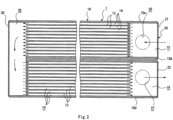
FIG. 2 is a schematic transverse sectional view for illustrating main portions of the cooler according to the first embodiment. -
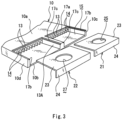
FIG. 3 is an exploded perspective view for illustrating a cooling plate, and a refrigerant inlet side lid half segment and a refrigerant outlet side lid half segment which form a first upper lid member in the first embodiment. -
FIG. 4 is an exploded perspective view for illustrating the cooling plate and a second upper lid member in the first embodiment. -
FIG. 5 (a) is a plan view for illustrating a joint portion between the cooling plate and the first upper lid member in the first embodiment. -
FIG. 5(b) is a side view for illustrating the joint portion between the cooling plate and the first upper lid member in the first embodiment. -
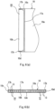
FIG. 6 (a) is a plan view for illustrating a joint portion between the cooling plate and the second upper lid member in the first embodiment. -
FIG. 6(b) is a side view for illustrating the joint portion between the cooling plate and the second upper lid member in the first embodiment. -
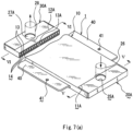
FIG. 7(a) is a perspective view for illustrating a cooler according to a second embodiment of the present invention, with a partial cross section. -
FIG. 7 (b) is a sectional view taken along the line V-V ofFIG. 7(a) . -
FIG. 7(c) is a sectional view taken along the line VI-VI ofFIG. 7(a) . -
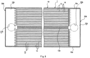
FIG. 8 is a schematic transverse sectional view for illustrating main portions of the cooler according to the second embodiment. -
FIG. 9 is an exploded perspective view for illustrating a cooling plate and a first upper lid member in the second embodiment. -
FIG. 10 is an exploded perspective view for illustrating the cooling plate and a second upper lid member in the second embodiment. -
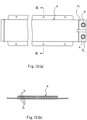
FIG. 11(a) is a plan view for illustrating a joint portion between the cooling plate and the first upper lid member in the second embodiment. -
FIG. 11(b) is a side view for illustrating the joint portion between the cooling plate and the first upper lid member in the second embodiment. -
FIG. 12(a) is a plan view for illustrating a joint portion between the cooling plate and the second upper lid member in the second embodiment. -
FIG. 12 (b) is a side view for illustrating the joint portion between the cooling plate and the second upper lid member in the second embodiment. -
FIG. 13 (a) is a schematic plan view for illustrating a related-art cooler. -
FIG. 13(b) is a sectional view taken along the line III-III ofFIG. 13(a) . -
FIG. 14(a) is a side view for illustrating the related-art cooler. -
FIG. 14 (b) is a sectional view taken along the line IV-IV ofFIG. 14(a) . - Now, embodiments of the present invention are described in detail with reference to the accompanying drawings. The following embodiments illustrated in
Figures 1-6 and13-14 are not according to the invention and are present for illustration purposes only. - As illustrated in
FIGS. 1 , acooler 1 includes acooling plate 10, a firstupper lid member 20, and a secondupper lid 30. Thecooling plate 10 is arranged in a bottom portion of abattery 2 that is to be used as, for example, a power supply for a motor configured to drive a vehicle. The firstupper lid member 20 is joined to afirst cutout portion 11 formed at one end of thecooling plate 10 in a longitudinal direction. The secondupper lid member 30 is joined to asecond cutout portion 12 formed at another end of thecooling plate 10 in the longitudinal direction. - The
cooling plate 10 is formed of a flat extruded profile made of aluminum or aluminum alloy (hereinafter referred to as "aluminum") having a substantially rectangular shape in plan view and including a plurality ofrefrigerant passages 14 partitioned by a plurality ofpartition walls 13 parallel to each other along the longitudinal direction. In this case, apartition wall 13A at the center is formed so as to be thicker thanother partition walls 13, and therefrigerant passages 14 are divided into a refrigerant inlet side and a refrigerant outlet side with respect to thepartition wall 13A at the center. - Further, the
first cutout portion 11 is formed at one end of thecooling plate 10 in the longitudinal direction. Thefirst cutout portion 11 is opened on an upper side and at an end portion in the longitudinal direction while leaving bothside walls partition wall 13 A at the center. - In this case, as illustrated in
FIG. 2 , thefirst cutout portion 11 has a refrigerantinlet side space 15 and a refrigerantoutlet side space 16. The refrigerantinlet side space 15 is formed by thepartition wall 13A at the center and oneside wall 10c. The refrigerantoutlet side space 16 is formed by thepartition wall 13A at the center and anotherside wall 10d. - The first
upper lid member 20 joined to thefirst cutout portion 11 includes a refrigerant inlet sidelid half segment 21 and a refrigerant outlet sidelid half segment 22. The refrigerant inlet sidelid half segment 21 is joined to thefirst cutout portion 11 so as to fill the refrigerantinlet side space 15 of thefirst cutout portion 11. The refrigerant outlet sidelid half segment 22 is joined to thefirst cutout portion 11 so as to fill the refrigerantoutlet side space 16 of thefirst cutout portion 11. - The refrigerant inlet side
lid half segment 21 and the refrigerant outlet sidelid half segment 22 are each formed of an aluminum plate material including ahorizontal part 23 that fills an upper portion of the refrigerantinlet side space 15 or the refrigerantoutlet side space 16 and avertical part 24 that fills an end portion in the longitudinal direction. In this case, the refrigerant inlet sidelid half segment 21 and the refrigerant outlet sidelid half segment 22 are each formed of a brazing sheet having a brazing filler metal bonded thereto as a surface material. - The
horizontal part 23 of the refrigerant inlet sidelid half segment 21 has arefrigerant inlet port 25, and a refrigerantinlet connection pipe 26 is joined to therefrigerant inlet port 25. Further, thehorizontal part 23 of the refrigerant outlet sidelid half segment 22 has arefrigerant outlet port 27, and a refrigerantoutlet connection pipe 28 is joined to therefrigerant outlet port 27. - As illustrated in
FIG. 3 , the refrigerant inlet sidelid half segment 21 and the refrigerant outlet sidelid half segment 22 described above are each joined by brazing to astep portion 17a formed at an opening end of anupper part 10a of the coolingplate 10, sidewall step portions 17b formed at upper ends of both theside walls wall step portions 17c formed at upper ends of thepartition wall 13A at the center, and end portions of both theside walls - Meanwhile, the
second cutout portion 12 is formed at another end of the coolingplate 10 in the longitudinal direction. Thesecond cutout portion 12 is opened on an upper side and at an end portion in the longitudinal direction while leaving both theside walls - The second
upper lid member 30 joined to thesecond cutout potion 12 is formed of an aluminum plate material including ahorizontal part 31 that fills an upper portion of both theside walls vertical part 32 that fills an end portion in the longitudinal direction. In this case, the secondupper lid member 30 is formed of a brazing sheet having a brazing filler metal bonded thereto as a surface material. - As illustrated in
FIG. 4 , the secondupper lid member 30 is joined by brazing to astep portion 17a formed at an opening end of theupper part 10a of the coolingplate 10, sidewall step portions 17b formed at upper ends of both theside walls side walls upper lid member 30 is joined to thesecond cutout portion 12, aflow passage space 35 causing the refrigerant inlet side and the refrigerant outlet side to communicate to each other is formed between the secondupper lid member 30 and the coolingplate 10. -
Flange portions 40 extend along the longitudinal direction at both ends of the coolingplate 10 in the width direction, and a mountinghole 41 in which a fixingscrew 50 can be inserted is formed at an appropriate position of each of theflange portions 40. The fixingscrew 50 to be inserted in the mountinghole 41 is inserted in a mounting hole (not shown) formed in abracket 3 supporting thebattery 2 through intermediation of aspacer 52, and anut 51 is threadedly engaged with the fixingscrew 50. Thus, it is possible to arrange thecooler 1 in the bottom portion of thebattery 2. - In the above-mentioned embodiment, description is given of the case in which the first upper lid member 20 (refrigerant inlet side
lid half segment 21 and refrigerant outlet side lid half segment 22) and the secondupper lid member 30 are each formed of a brazing sheet having a brazing filler metal bonded thereto as a surface material. However, it is not always required to have such configuration. Instead of forming the first upper lid member 20 (refrigerant inlet sidelid half segment 21 and refrigerant outlet side lid half segment 22) and the secondupper lid member 30 through use of a brazing sheet, for example, it may be possible to apply a brazing filler metal to a surface of the coolingplate 10 and join thecooling plate 10 by brazing to the first upper lid member 20 (refrigerant inlet sidelid half segment 21 and refrigerant outlet side lid half segment 22) and the secondupper lid member 30. - Further, as another brazing method, it may also be possible to use high-frequency brazing using a fluoride-based flux containing a powder brazing filler metal, specifically, a powdery aluminum alloy brazing filler metal, which contains 27 mass% to 37 mass% of Cu, 5 mass% to 10 mass% of Si, and the balance of Al and inevitable impurities, and 11 mass% or more of CsF as a solid content.
- With the cooler according to the first embodiment having the above-mentioned configuration, the first
upper lid member 20, which has therefrigerant inlet port 25 and therefrigerant outlet port 27 respectively communicating to the refrigerant inlet side and the refrigerant outlet side, is joined to thefirst cutout portion 11 formed at one end of the coolingplate 10 having a flat shape, and the secondupper lid member 30, which forms theflow passage space 35 causing the refrigerant inlet side and the refrigerant outlet side to communicate to each other, is joined by brazing to thesecond cutout portion 12 formed at another end of the coolingplate 10. Therefore, as compared to the case in which the refrigerant inlet connection pipe and the refrigerant outlet connection pipe are joined through use of a joint member, the number of components can be decreased, and the space can be reduced. - Further, the refrigerant inlet side
lid half segment 21 and the refrigerant outlet sidelid half segment 22, which form the firstupper lid member 20, are each joined to thestep portion 17a formed at the opening end of the upper part of the coolingplate 10, the sidewall step portions 17b formed at the upper ends of both theside walls wall step portions 17c formed at the upper ends of thepartition wall 13A, and the end portions of both theside walls upper lid member 30 is joined to thestep portion 17a formed at the opening end of theupper part 10a of the coolingplate 10, the sidewall step portions 17b formed at the upper ends of both theside walls plate 10 and the first upper lid member 20 (refrigerant inlet sidelid half segment 21 and refrigerant outlet side lid half segment 22), and joining between the coolingplate 10 and the secondupper lid member 30 can be set easier and stronger. - In the first embodiment, the cooler of two-path (U-turn) type refrigerant flow is described. However, the present invention is also applicable to a cooler of one-path (zero-turn) type refrigerant flow according to a second embodiment of the present invention described below.
- As illustrated in
FIGS. 7 andFIG. 8 , thecooler 1 according to the second embodiment includes afirst cutout portion 11A, a second cut outportion 12A, a firstupper lid member 20A, and a secondupper lid member 30A. Thefirst cutout portion 11A is formed at one end of the coolingplate 10 in the longitudinal direction and is opened on an upper side and at an end portion in the longitudinal direction while leaving both theside walls second cutout portion 12A is formed at another end of the coolingplate 10 in the longitudinal direction and is opened on an upper side and at an end portion in the longitudinal direction while leaving both theside walls upper lid member 20A is joined to thefirst cutout portion 11A and has arefrigerant inlet port 25A communicating to a refrigerantinlet side space 15A formed by both theside walls upper lid member 30A is joined to thesecond cutout portion 12A and has arefrigerant outlet port 27A communicating to a refrigerantoutlet side space 16A formed by both theside walls - The first
upper lid member 20A is formed of an aluminum plate material including thehorizontal part 23 that fills an upper portion of the refrigerantinlet side space 15A and avertical part 24 that fills the end portion in the longitudinal direction. A projectingpiece 23a having a protruding arc shape, which extends outward, is formed in a center portion on a distal end side of thehorizontal part 23 of the firstupper lid member 20A. Further, therefrigerant inlet port 25A is formed in thehorizontal part 23, and the refrigerantinlet connection pipe 26 is joined to therefrigerant inlet port 25A. - As illustrated in
FIG. 9 , the firstupper lid member 20A is joined by brazing to thestep portion 17a and an arc-shaped partitionwall step portion 17d formed at an opening end of theupper part 10a of the coolingplate 10, the sidewall step portions 17b formed at upper ends of both theside walls side walls piece 23a having a protruding arc shape is engaged with the arc-shaped partitionwall step portion 17d. - As described above, when brazing is performed under a state in which the projecting
piece 23a having a protruding arc shape is engaged with the arc-shaped partitionwall step portion 17d, the firstupper lid member 20A is positioned with respect to thefirst cutout portion 11A to perform brazing easily and securely. - Meanwhile, the second
upper lid member 30A joined to thesecond cutout portion 12A is formed of an aluminum plate material including thehorizontal part 31 that fills an upper portion of both theside walls vertical part 32 that fills the end portion in the longitudinal direction. A projectingpiece 31a having a protruding arc shape, which extends outward, is formed in a center portion on a distal end side of thehorizontal part 31 of the secondupper lid member 30A. Further, arefrigerant outlet port 27A is formed in thehorizontal part 31, and the refrigerantoutlet connection pipe 28 is joined to therefrigerant outlet port 27A. - As illustrated in
FIG. 10 , the secondupper lid member 30A is joined by brazing to thestep portion 17a and the arc-shaped partitionwall step portion 17d formed at an opening end of theupper part 10a of the coolingplate 10, the sidewall step portions 17b formed at upper ends of both theside walls side walls piece 31a having a protruding arc shape is engaged with the arc-shaped partitionwall step portion 17d. Thus, in the same manner as in the case of thefirst cutout portion 11A and the firstupper lid member 20A, brazing of the secondupper lid member 30A with respect to thesecond cutout portion 12A can be performed easily and securely. - The first
upper lid member 20A and the secondupper lid member 30A formed as described above are formed of an aluminum plate material having the same shape. - In the second embodiment, other portions are the same as those of the first embodiment. Therefore, the same portions are denoted by the same reference symbols, and description thereof is omitted.
- with the cooler according to the second embodiment having the above-mentioned configuration, the first
upper lid member 20A having therefrigerant inlet port 25A and the secondupper lid member 30A having therefrigerant outlet port 27A are joined to thefirst cutout portion 11A and thesecond cutout portion 12A formed at both the ends of the coolingplate 10 having a flat shape in the longitudinal direction, and the firstupper lid member 20A and the secondupper lid member 30A are formed of the common aluminum plate material. Therefore, the number of components can be decreased, and the space can be reduced. - When the first
upper lid member 20A and the secondupper lid member 30A are joined to thestep portion 17a and the arc-shaped partitionwall step portion 17d formed at the opening end of theupper part 10a of the coolingplate 10, the sidewall step portions 17b formed at upper ends of both theside walls side walls plate 10 and the firstupper lid member 20A and joining between the coolingplate 10 and the secondupper lid member 30A can further be set easier and stronger. - In the above-mentioned embodiments, description is given of the case in which the cooler according to the present invention is used for cooling heat generated from the
battery 2 to be used as a power supply for a motor configured to drive a vehicle. However, the cooler according to the present invention is not limited thereto, and the present invention is also applicable to a cooler configured to cool heat generated from a power device such as an inverter or a semiconductor element. -
- 10 cooling plate
- 10a upper part
- 10b lower part
- 10c, 10d side wall
- 13, 13A partition wall
- 14 refrigerant passage
- 15, 15A refrigerant inlet side space
- 16, 16A refrigerant outlet side space
- 17a step portion
- 17b side wall step portion
- 17c partition wall step portion
- 17d arc-shaped partition wall step portion
- 20, 20A first upper lid member
- 21 refrigerant inlet side lid half segment
- 22 refrigerant outlet side lid half segment
- 25, 25A refrigerant inlet port
- 27, 27A refrigerant outlet port
- 30, 30A second upper lid member
- 35 flow passage space
Claims (1)
- A cooler (1), comprising:a cooling plate (10) being formed of a flat extruded profile made of aluminum or aluminum alloy and having a flat shape and including a plurality of refrigerant passages (14) partitioned by a plurality of partition walls (13, 13A) parallel to each other along a longitudinal direction;a first cutout portion (11A), which is formed at one end of the cooling plate in the longitudinal direction, and is opened on an upper side and at an end portion in the longitudinal direction while leaving both side walls (10c, 10d) in a width direction;a second cutout portion (12A), which is formed at another end of the cooling plate in the longitudinal direction, and is opened on the upper side and at an end portion in the longitudinal direction while leaving both the side walls in the width direction;a first upper lid member (20A), which is joined to the first cutout portion, and has a refrigerant inlet port (25A) communicating to a refrigerant inlet side space (15A) formed by both the side walls; anda second upper lid member (30A), which is joined to the second cutout portion, and has a refrigerant outlet port (27A) communicating to a refrigerant outlet side space (16A) formed by both the side walls, characterized in that the first upper lid member (20A) is formed of an aluminum plate material including a horizontal part (23) that fills an upper portion of the refrigerant inlet side space (15A) and a vertical part (24) that fills the end portion in the longitudinal direction, and a projecting piece (23a) having a protruding arc shape, which extends outward, is formed in a center portion on a distal end side of the horizontal part (23) of the first upper lid member (20A), the refrigerant inlet port (25A) being formed in the horizontal part (23) of the first upper lid member (20A), andthe first upper lid member (20A) is joined by brazing to a step portion (17a) and an arc-shaped partition wall step portion (17d) formed at an opening end of an upper part (10a) of the cooling plate (10), side wall step portions (17b) formed at upper ends of both the side walls (10c, 10d), and one end side end portions of both the side walls, joining by brazing being performed under a state in which the projecting piece (23a) of the first upper lid member (20A) is engaged with the arc-shaped partition wall step portion (17d) ;the second upper lid member (30A) is formed of an aluminum plate material including a horizontal part (31) that fills an upper portion of both the side walls (10c, 10d) and a vertical part (32) that fills the other end portion in the longitudinal direction, and a projecting piece (31a) having a protruding arc shape, which extends outward, is formed in a center portion on a distal end side of the horizontal part (31) of the second upper lid member (30A), the refrigerant outlet port (27A) being formed in the horizontal part (31) of the second upper lid member (30A), andthe second upper lid member (30A) is joined by brazing to a step portion (17a) and an arc-shaped partition wall step portion (17d) formed at another opening end of the upper part (10a) of the cooling plate (10), the side wall step portions (17b) formed at upper ends of both the side walls (10c, 10d), and another end side end portions of both the side walls (10c, 10d), joining by brazing being performed under a state in which the projecting piece (31a) of the second upper lid member (30A) is engaged with the corresponding arc-shaped partition wall step portion (17d).
Applications Claiming Priority (3)
| Application Number | Priority Date | Filing Date | Title |
|---|---|---|---|
| JP2015154707 | 2015-08-05 | ||
| PCT/JP2016/003578 WO2017022244A1 (en) | 2015-08-05 | 2016-08-03 | Cooler |
| EP16832525.6A EP3333966B1 (en) | 2015-08-05 | 2016-08-03 | Cooler |
Related Parent Applications (2)
| Application Number | Title | Priority Date | Filing Date |
|---|---|---|---|
| EP16832525.6A Division-Into EP3333966B1 (en) | 2015-08-05 | 2016-08-03 | Cooler |
| EP16832525.6A Division EP3333966B1 (en) | 2015-08-05 | 2016-08-03 | Cooler |
Publications (2)
| Publication Number | Publication Date |
|---|---|
| EP3595080A1 EP3595080A1 (en) | 2020-01-15 |
| EP3595080B1 true EP3595080B1 (en) | 2023-12-13 |
Family
ID=57942743
Family Applications (2)
| Application Number | Title | Priority Date | Filing Date |
|---|---|---|---|
| EP19187111.0A Active EP3595080B1 (en) | 2015-08-05 | 2016-08-03 | Cooler |
| EP16832525.6A Active EP3333966B1 (en) | 2015-08-05 | 2016-08-03 | Cooler |
Family Applications After (1)
| Application Number | Title | Priority Date | Filing Date |
|---|---|---|---|
| EP16832525.6A Active EP3333966B1 (en) | 2015-08-05 | 2016-08-03 | Cooler |
Country Status (5)
| Country | Link |
|---|---|
| US (1) | US10648748B2 (en) |
| EP (2) | EP3595080B1 (en) |
| JP (1) | JP6494134B2 (en) |
| CN (1) | CN107851867B (en) |
| WO (1) | WO2017022244A1 (en) |
Families Citing this family (23)
| Publication number | Priority date | Publication date | Assignee | Title |
|---|---|---|---|---|
| JP6631637B2 (en) * | 2015-10-26 | 2020-01-15 | 日本軽金属株式会社 | Cooler manufacturing method |
| KR101822304B1 (en) * | 2016-10-24 | 2018-01-25 | 현대자동차주식회사 | Apparatus for cooling battery |
| KR20250107935A (en) * | 2018-03-16 | 2025-07-14 | 로미오 시스템즈, 인크. | Cold plate blade for battery modules |
| CN112020792B (en) * | 2018-04-11 | 2025-01-03 | 肯联铝业辛根有限责任公司 | Thermal management devices for batteries |
| EP3564992B1 (en) * | 2018-05-02 | 2021-07-07 | EKWB d.o.o. | Fluid-based cooling device for cooling at least two distinct first heat-generating elements of a heat source assembly |
| CN110531571B (en) * | 2018-05-24 | 2021-08-24 | 中强光电股份有限公司 | Liquid-cooled radiator |
| CN110543069A (en) * | 2018-05-28 | 2019-12-06 | 中强光电股份有限公司 | Liquid-cooled radiator |
| US11316216B2 (en) * | 2018-10-24 | 2022-04-26 | Dana Canada Corporation | Modular heat exchangers for battery thermal modulation |
| FR3097627B1 (en) * | 2019-06-18 | 2022-12-02 | Valeo Systemes Thermiques | Liquid circulation heat exchanger and connector for such an exchanger |
| JP7583533B2 (en) * | 2020-04-24 | 2024-11-14 | 株式会社日本クライメイトシステムズ | Heat exchanger for vehicle battery cooling system |
| FR3125636B1 (en) * | 2021-07-26 | 2024-07-12 | Valeo Systemes Thermiques | Thermal regulation device for cooling electrical energy storage devices. |
| CN116207391A (en) * | 2021-12-01 | 2023-06-02 | Cps科技控股有限公司 | Cooling plate and battery pack including the cooling plate |
| JP7685462B2 (en) * | 2022-04-11 | 2025-05-29 | 三桜工業株式会社 | cooler |
| JPWO2023210711A1 (en) * | 2022-04-28 | 2023-11-02 | ||
| EP4311384A1 (en) * | 2022-07-22 | 2024-01-24 | Aptiv Technologies Limited | Cooling system with flow guiding element |
| KR102792494B1 (en) * | 2023-06-02 | 2025-04-08 | 주식회사 엘지에너지솔루션 | Heat sink assembly |
| FR3150280A1 (en) * | 2023-06-20 | 2024-12-27 | Valeo Systemes Thermiques | Thermal regulation device |
| KR20250038013A (en) * | 2023-09-11 | 2025-03-19 | 주식회사 엘지에너지솔루션 | Heat sink assembly |
| JP2025059181A (en) * | 2023-09-29 | 2025-04-10 | 三桜工業株式会社 | Cooler |
| US12492869B2 (en) * | 2024-01-31 | 2025-12-09 | JWS Technology CO., LTD. | Immersion liquid cooling heat sink |
| WO2025198059A1 (en) * | 2024-03-22 | 2025-09-25 | 三桜工業株式会社 | Cooler and assembly |
| DE102024116356A1 (en) * | 2024-06-11 | 2025-12-11 | Akg Verwaltungsgesellschaft Mbh | Heat exchanger |
| DE202025100553U1 (en) | 2025-02-04 | 2025-02-18 | Erbslöh Aluminium Gmbh | Cooling profile for a battery module with at least one battery unit |
Family Cites Families (28)
| Publication number | Priority date | Publication date | Assignee | Title |
|---|---|---|---|---|
| US2981520A (en) * | 1959-11-09 | 1961-04-25 | Borg Warner | Plate-type heat-exchangers |
| US3264756A (en) * | 1964-06-01 | 1966-08-09 | Pennsalt Chemicals Corp | Drying tray |
| US4578324A (en) | 1984-10-05 | 1986-03-25 | Ford Aerospace & Communications Corporation | Active cooling system for electrochemical cells |
| US5170319A (en) * | 1990-06-04 | 1992-12-08 | International Business Machines Corporation | Enhanced multichip module cooling with thermally optimized pistons and closely coupled convective cooling channels |
| WO2001017055A1 (en) * | 1999-08-27 | 2001-03-08 | Tokyo R & D Co., Ltd. | Battery cooling structure |
| JP2002098454A (en) * | 2000-07-21 | 2002-04-05 | Mitsubishi Materials Corp | Liquid-cooled heat sink and method of manufacturing the same |
| WO2005088714A1 (en) * | 2004-03-08 | 2005-09-22 | Remmele Engineering, Inc. | Cold plate and method of making the same |
| CN2932273Y (en) * | 2006-04-21 | 2007-08-08 | 王磊 | A cold and heat exchanger |
| EP1921676B1 (en) * | 2006-11-13 | 2019-03-06 | Aavid Thermalloy S.r.l. | Heat sink |
| CN101610664B (en) * | 2008-06-20 | 2014-05-14 | 萨帕铝型材(上海)有限公司 | Liquid cooler and manufacture method thereof |
| JP2010050000A (en) | 2008-08-22 | 2010-03-04 | Sanyo Electric Co Ltd | Power source device for vehicle |
| TW201116794A (en) * | 2009-11-10 | 2011-05-16 | Pegatron Corp | Vapor chamber and manufacturing method thereof |
| WO2012138833A2 (en) | 2011-04-05 | 2012-10-11 | A123 Systems, Inc. | Cooling assembly and method of control |
| JP5758991B2 (en) * | 2011-05-06 | 2015-08-05 | 三菱電機株式会社 | Heat exchanger and refrigeration cycle apparatus including the same |
| DE102011077838A1 (en) * | 2011-06-20 | 2012-12-20 | Behr Gmbh & Co. Kg | Heat exchanger and method for producing a heat exchanger |
| JP2013254787A (en) * | 2012-06-05 | 2013-12-19 | Sumitomo Light Metal Ind Ltd | Heat exchanger and manufacturing method of the same |
| KR101431550B1 (en) * | 2012-07-03 | 2014-10-06 | (주)인벤티오 | Apparatus for cooling battery and method of producing the same |
| US9593891B2 (en) * | 2012-09-28 | 2017-03-14 | Mahle International Gmbh | Heat exchanger |
| NL2009680C2 (en) * | 2012-10-23 | 2014-04-29 | Dejatech Ges B V | Heat exchanger and method for manufacturing such. |
| WO2014147033A1 (en) * | 2013-03-18 | 2014-09-25 | Behr Gmbh & Co. Kg | Layered heat transfer device and method for producing a layered heat transfer device |
| DE102013011692A1 (en) | 2013-07-12 | 2015-01-29 | Daimler Ag | Energy storage device with a tempering device, method for producing the energy storage device |
| DE102013215358A1 (en) * | 2013-08-05 | 2015-02-19 | Behr Gmbh & Co. Kg | Heat exchanger for cooling a vehicle battery, in particular for hybrid or electric vehicles |
| JP2016038120A (en) * | 2014-08-05 | 2016-03-22 | カルソニックカンセイ株式会社 | Heat exchanger |
| US9362598B2 (en) * | 2014-08-25 | 2016-06-07 | Ford Global Technologies, Llc | Traction battery assembly with thermal device |
| DE102014223047A1 (en) * | 2014-11-12 | 2016-05-12 | Robert Bosch Gmbh | Receptacle for a battery module and battery module having such a receptacle |
| US10263301B2 (en) * | 2015-01-09 | 2019-04-16 | Dana Canada Corporation | Counter-flow heat exchanger for battery thermal management applications |
| US10497998B2 (en) * | 2016-05-09 | 2019-12-03 | Nikola Corporation | Electric battery assembly |
| CN110622349B (en) * | 2017-05-16 | 2023-05-02 | 达纳加拿大公司 | Counterflow Heat Exchanger with Side Entry Fitting |
-
2016
- 2016-08-03 WO PCT/JP2016/003578 patent/WO2017022244A1/en not_active Ceased
- 2016-08-03 CN CN201680045340.3A patent/CN107851867B/en active Active
- 2016-08-03 JP JP2017532384A patent/JP6494134B2/en active Active
- 2016-08-03 US US15/749,359 patent/US10648748B2/en active Active
- 2016-08-03 EP EP19187111.0A patent/EP3595080B1/en active Active
- 2016-08-03 EP EP16832525.6A patent/EP3333966B1/en active Active
Also Published As
| Publication number | Publication date |
|---|---|
| EP3333966B1 (en) | 2020-03-04 |
| CN107851867B (en) | 2020-09-29 |
| EP3595080A1 (en) | 2020-01-15 |
| EP3333966A4 (en) | 2019-03-27 |
| JPWO2017022244A1 (en) | 2018-05-31 |
| EP3333966A1 (en) | 2018-06-13 |
| JP6494134B2 (en) | 2019-04-03 |
| CN107851867A (en) | 2018-03-27 |
| WO2017022244A1 (en) | 2017-02-09 |
| US20180238642A1 (en) | 2018-08-23 |
| US10648748B2 (en) | 2020-05-12 |
Similar Documents
| Publication | Publication Date | Title |
|---|---|---|
| EP3595080B1 (en) | Cooler | |
| JP6828767B2 (en) | How to make a cooler | |
| EP2159838B1 (en) | Liquid-cooled-type cooling device | |
| JP5880491B2 (en) | Inverter case | |
| EP2159839B1 (en) | Liquid-cooled-type cooling device | |
| US11145918B2 (en) | Battery system for an electric vehicle | |
| CN110718724A (en) | Cooling units, battery temperature control systems, and vehicles | |
| US20210261202A1 (en) | Vehicle lower part structure | |
| US9593891B2 (en) | Heat exchanger | |
| JP2017184523A (en) | Mechatronic drive device | |
| JP5783465B2 (en) | Busbar and electrical circuit | |
| US11802504B2 (en) | Vehicle side rail, electric transmission system, powertrain assembly and corresponding vehicle | |
| CN106961184A (en) | Fluid-cooled electric drive assembly, power train, vehicle and method | |
| JP5849883B2 (en) | Cold storage heat exchanger | |
| WO2017068329A1 (en) | Apparatus for moulding battery components | |
| JP2011155179A (en) | Cooler | |
| KR20210121225A (en) | arrangement of vehicle engine room | |
| JP2025013145A (en) | Manifold | |
| JP7095645B2 (en) | Power converter | |
| CN121469733A (en) | Vehicle front structure | |
| CN121079213A (en) | Mounting structure of heat exchanger | |
| CN104925000A (en) | Assembly provided with sliding joint and used for fastening vehicle components and assembling method | |
| JP2014239113A (en) | Temperature control plate |
Legal Events
| Date | Code | Title | Description |
|---|---|---|---|
| PUAI | Public reference made under article 153(3) epc to a published international application that has entered the european phase |
Free format text: ORIGINAL CODE: 0009012 |
|
| STAA | Information on the status of an ep patent application or granted ep patent |
Free format text: STATUS: THE APPLICATION HAS BEEN PUBLISHED |
|
| AC | Divisional application: reference to earlier application |
Ref document number: 3333966 Country of ref document: EP Kind code of ref document: P |
|
| AK | Designated contracting states |
Kind code of ref document: A1 Designated state(s): AL AT BE BG CH CY CZ DE DK EE ES FI FR GB GR HR HU IE IS IT LI LT LU LV MC MK MT NL NO PL PT RO RS SE SI SK SM TR |
|
| STAA | Information on the status of an ep patent application or granted ep patent |
Free format text: STATUS: REQUEST FOR EXAMINATION WAS MADE |
|
| STAA | Information on the status of an ep patent application or granted ep patent |
Free format text: STATUS: EXAMINATION IS IN PROGRESS |
|
| 17P | Request for examination filed |
Effective date: 20200625 |
|
| RBV | Designated contracting states (corrected) |
Designated state(s): AL AT BE BG CH CY CZ DE DK EE ES FI FR GB GR HR HU IE IS IT LI LT LU LV MC MK MT NL NO PL PT RO RS SE SI SK SM TR |
|
| 17Q | First examination report despatched |
Effective date: 20200713 |
|
| GRAP | Despatch of communication of intention to grant a patent |
Free format text: ORIGINAL CODE: EPIDOSNIGR1 |
|
| STAA | Information on the status of an ep patent application or granted ep patent |
Free format text: STATUS: GRANT OF PATENT IS INTENDED |
|
| INTG | Intention to grant announced |
Effective date: 20230630 |
|
| GRAS | Grant fee paid |
Free format text: ORIGINAL CODE: EPIDOSNIGR3 |
|
| GRAA | (expected) grant |
Free format text: ORIGINAL CODE: 0009210 |
|
| STAA | Information on the status of an ep patent application or granted ep patent |
Free format text: STATUS: THE PATENT HAS BEEN GRANTED |
|
| AC | Divisional application: reference to earlier application |
Ref document number: 3333966 Country of ref document: EP Kind code of ref document: P |
|
| AK | Designated contracting states |
Kind code of ref document: B1 Designated state(s): AL AT BE BG CH CY CZ DE DK EE ES FI FR GB GR HR HU IE IS IT LI LT LU LV MC MK MT NL NO PL PT RO RS SE SI SK SM TR |
|
| P01 | Opt-out of the competence of the unified patent court (upc) registered |
Effective date: 20231107 |
|
| REG | Reference to a national code |
Ref country code: GB Ref legal event code: FG4D |
|
| REG | Reference to a national code |
Ref country code: CH Ref legal event code: EP |
|
| REG | Reference to a national code |
Ref country code: DE Ref legal event code: R096 Ref document number: 602016084779 Country of ref document: DE |
|
| REG | Reference to a national code |
Ref country code: IE Ref legal event code: FG4D |
|
| PG25 | Lapsed in a contracting state [announced via postgrant information from national office to epo] |
Ref country code: GR Free format text: LAPSE BECAUSE OF FAILURE TO SUBMIT A TRANSLATION OF THE DESCRIPTION OR TO PAY THE FEE WITHIN THE PRESCRIBED TIME-LIMIT Effective date: 20240314 |
|
| REG | Reference to a national code |
Ref country code: LT Ref legal event code: MG9D |
|
| PG25 | Lapsed in a contracting state [announced via postgrant information from national office to epo] |
Ref country code: LT Free format text: LAPSE BECAUSE OF FAILURE TO SUBMIT A TRANSLATION OF THE DESCRIPTION OR TO PAY THE FEE WITHIN THE PRESCRIBED TIME-LIMIT Effective date: 20231213 |
|
| REG | Reference to a national code |
Ref country code: NL Ref legal event code: MP Effective date: 20231213 |
|
| PG25 | Lapsed in a contracting state [announced via postgrant information from national office to epo] |
Ref country code: ES Free format text: LAPSE BECAUSE OF FAILURE TO SUBMIT A TRANSLATION OF THE DESCRIPTION OR TO PAY THE FEE WITHIN THE PRESCRIBED TIME-LIMIT Effective date: 20231213 |
|
| PG25 | Lapsed in a contracting state [announced via postgrant information from national office to epo] |
Ref country code: LT Free format text: LAPSE BECAUSE OF FAILURE TO SUBMIT A TRANSLATION OF THE DESCRIPTION OR TO PAY THE FEE WITHIN THE PRESCRIBED TIME-LIMIT Effective date: 20231213 Ref country code: GR Free format text: LAPSE BECAUSE OF FAILURE TO SUBMIT A TRANSLATION OF THE DESCRIPTION OR TO PAY THE FEE WITHIN THE PRESCRIBED TIME-LIMIT Effective date: 20240314 Ref country code: ES Free format text: LAPSE BECAUSE OF FAILURE TO SUBMIT A TRANSLATION OF THE DESCRIPTION OR TO PAY THE FEE WITHIN THE PRESCRIBED TIME-LIMIT Effective date: 20231213 Ref country code: BG Free format text: LAPSE BECAUSE OF FAILURE TO SUBMIT A TRANSLATION OF THE DESCRIPTION OR TO PAY THE FEE WITHIN THE PRESCRIBED TIME-LIMIT Effective date: 20240313 |
|
| REG | Reference to a national code |
Ref country code: AT Ref legal event code: MK05 Ref document number: 1641259 Country of ref document: AT Kind code of ref document: T Effective date: 20231213 |
|
| PG25 | Lapsed in a contracting state [announced via postgrant information from national office to epo] |
Ref country code: NL Free format text: LAPSE BECAUSE OF FAILURE TO SUBMIT A TRANSLATION OF THE DESCRIPTION OR TO PAY THE FEE WITHIN THE PRESCRIBED TIME-LIMIT Effective date: 20231213 |
|
| PG25 | Lapsed in a contracting state [announced via postgrant information from national office to epo] |
Ref country code: SE Free format text: LAPSE BECAUSE OF FAILURE TO SUBMIT A TRANSLATION OF THE DESCRIPTION OR TO PAY THE FEE WITHIN THE PRESCRIBED TIME-LIMIT Effective date: 20231213 Ref country code: RS Free format text: LAPSE BECAUSE OF FAILURE TO SUBMIT A TRANSLATION OF THE DESCRIPTION OR TO PAY THE FEE WITHIN THE PRESCRIBED TIME-LIMIT Effective date: 20231213 Ref country code: NO Free format text: LAPSE BECAUSE OF FAILURE TO SUBMIT A TRANSLATION OF THE DESCRIPTION OR TO PAY THE FEE WITHIN THE PRESCRIBED TIME-LIMIT Effective date: 20240313 Ref country code: NL Free format text: LAPSE BECAUSE OF FAILURE TO SUBMIT A TRANSLATION OF THE DESCRIPTION OR TO PAY THE FEE WITHIN THE PRESCRIBED TIME-LIMIT Effective date: 20231213 Ref country code: LV Free format text: LAPSE BECAUSE OF FAILURE TO SUBMIT A TRANSLATION OF THE DESCRIPTION OR TO PAY THE FEE WITHIN THE PRESCRIBED TIME-LIMIT Effective date: 20231213 Ref country code: HR Free format text: LAPSE BECAUSE OF FAILURE TO SUBMIT A TRANSLATION OF THE DESCRIPTION OR TO PAY THE FEE WITHIN THE PRESCRIBED TIME-LIMIT Effective date: 20231213 |
|
| PG25 | Lapsed in a contracting state [announced via postgrant information from national office to epo] |
Ref country code: IS Free format text: LAPSE BECAUSE OF FAILURE TO SUBMIT A TRANSLATION OF THE DESCRIPTION OR TO PAY THE FEE WITHIN THE PRESCRIBED TIME-LIMIT Effective date: 20240413 |
|
| PG25 | Lapsed in a contracting state [announced via postgrant information from national office to epo] |
Ref country code: AT Free format text: LAPSE BECAUSE OF FAILURE TO SUBMIT A TRANSLATION OF THE DESCRIPTION OR TO PAY THE FEE WITHIN THE PRESCRIBED TIME-LIMIT Effective date: 20231213 Ref country code: CZ Free format text: LAPSE BECAUSE OF FAILURE TO SUBMIT A TRANSLATION OF THE DESCRIPTION OR TO PAY THE FEE WITHIN THE PRESCRIBED TIME-LIMIT Effective date: 20231213 |
|
| PG25 | Lapsed in a contracting state [announced via postgrant information from national office to epo] |
Ref country code: SK Free format text: LAPSE BECAUSE OF FAILURE TO SUBMIT A TRANSLATION OF THE DESCRIPTION OR TO PAY THE FEE WITHIN THE PRESCRIBED TIME-LIMIT Effective date: 20231213 |
|
| PG25 | Lapsed in a contracting state [announced via postgrant information from national office to epo] |
Ref country code: SM Free format text: LAPSE BECAUSE OF FAILURE TO SUBMIT A TRANSLATION OF THE DESCRIPTION OR TO PAY THE FEE WITHIN THE PRESCRIBED TIME-LIMIT Effective date: 20231213 Ref country code: SK Free format text: LAPSE BECAUSE OF FAILURE TO SUBMIT A TRANSLATION OF THE DESCRIPTION OR TO PAY THE FEE WITHIN THE PRESCRIBED TIME-LIMIT Effective date: 20231213 Ref country code: RO Free format text: LAPSE BECAUSE OF FAILURE TO SUBMIT A TRANSLATION OF THE DESCRIPTION OR TO PAY THE FEE WITHIN THE PRESCRIBED TIME-LIMIT Effective date: 20231213 Ref country code: IT Free format text: LAPSE BECAUSE OF FAILURE TO SUBMIT A TRANSLATION OF THE DESCRIPTION OR TO PAY THE FEE WITHIN THE PRESCRIBED TIME-LIMIT Effective date: 20231213 Ref country code: IS Free format text: LAPSE BECAUSE OF FAILURE TO SUBMIT A TRANSLATION OF THE DESCRIPTION OR TO PAY THE FEE WITHIN THE PRESCRIBED TIME-LIMIT Effective date: 20240413 Ref country code: EE Free format text: LAPSE BECAUSE OF FAILURE TO SUBMIT A TRANSLATION OF THE DESCRIPTION OR TO PAY THE FEE WITHIN THE PRESCRIBED TIME-LIMIT Effective date: 20231213 Ref country code: CZ Free format text: LAPSE BECAUSE OF FAILURE TO SUBMIT A TRANSLATION OF THE DESCRIPTION OR TO PAY THE FEE WITHIN THE PRESCRIBED TIME-LIMIT Effective date: 20231213 Ref country code: AT Free format text: LAPSE BECAUSE OF FAILURE TO SUBMIT A TRANSLATION OF THE DESCRIPTION OR TO PAY THE FEE WITHIN THE PRESCRIBED TIME-LIMIT Effective date: 20231213 |
|
| PG25 | Lapsed in a contracting state [announced via postgrant information from national office to epo] |
Ref country code: PL Free format text: LAPSE BECAUSE OF FAILURE TO SUBMIT A TRANSLATION OF THE DESCRIPTION OR TO PAY THE FEE WITHIN THE PRESCRIBED TIME-LIMIT Effective date: 20231213 Ref country code: PT Free format text: LAPSE BECAUSE OF FAILURE TO SUBMIT A TRANSLATION OF THE DESCRIPTION OR TO PAY THE FEE WITHIN THE PRESCRIBED TIME-LIMIT Effective date: 20240415 |
|
| PG25 | Lapsed in a contracting state [announced via postgrant information from national office to epo] |
Ref country code: PT Free format text: LAPSE BECAUSE OF FAILURE TO SUBMIT A TRANSLATION OF THE DESCRIPTION OR TO PAY THE FEE WITHIN THE PRESCRIBED TIME-LIMIT Effective date: 20240415 Ref country code: PL Free format text: LAPSE BECAUSE OF FAILURE TO SUBMIT A TRANSLATION OF THE DESCRIPTION OR TO PAY THE FEE WITHIN THE PRESCRIBED TIME-LIMIT Effective date: 20231213 |
|
| REG | Reference to a national code |
Ref country code: DE Ref legal event code: R097 Ref document number: 602016084779 Country of ref document: DE |
|
| PG25 | Lapsed in a contracting state [announced via postgrant information from national office to epo] |
Ref country code: DK Free format text: LAPSE BECAUSE OF FAILURE TO SUBMIT A TRANSLATION OF THE DESCRIPTION OR TO PAY THE FEE WITHIN THE PRESCRIBED TIME-LIMIT Effective date: 20231213 |
|
| PLBE | No opposition filed within time limit |
Free format text: ORIGINAL CODE: 0009261 |
|
| STAA | Information on the status of an ep patent application or granted ep patent |
Free format text: STATUS: NO OPPOSITION FILED WITHIN TIME LIMIT |
|
| PG25 | Lapsed in a contracting state [announced via postgrant information from national office to epo] |
Ref country code: SI Free format text: LAPSE BECAUSE OF FAILURE TO SUBMIT A TRANSLATION OF THE DESCRIPTION OR TO PAY THE FEE WITHIN THE PRESCRIBED TIME-LIMIT Effective date: 20231213 |
|
| PG25 | Lapsed in a contracting state [announced via postgrant information from national office to epo] |
Ref country code: SI Free format text: LAPSE BECAUSE OF FAILURE TO SUBMIT A TRANSLATION OF THE DESCRIPTION OR TO PAY THE FEE WITHIN THE PRESCRIBED TIME-LIMIT Effective date: 20231213 Ref country code: DK Free format text: LAPSE BECAUSE OF FAILURE TO SUBMIT A TRANSLATION OF THE DESCRIPTION OR TO PAY THE FEE WITHIN THE PRESCRIBED TIME-LIMIT Effective date: 20231213 |
|
| 26N | No opposition filed |
Effective date: 20240916 |
|
| REG | Reference to a national code |
Ref country code: CH Ref legal event code: PL |
|
| PG25 | Lapsed in a contracting state [announced via postgrant information from national office to epo] |
Ref country code: LU Free format text: LAPSE BECAUSE OF NON-PAYMENT OF DUE FEES Effective date: 20240803 |
|
| GBPC | Gb: european patent ceased through non-payment of renewal fee |
Effective date: 20240803 |
|
| PG25 | Lapsed in a contracting state [announced via postgrant information from national office to epo] |
Ref country code: CH Free format text: LAPSE BECAUSE OF NON-PAYMENT OF DUE FEES Effective date: 20240831 Ref country code: MC Free format text: LAPSE BECAUSE OF FAILURE TO SUBMIT A TRANSLATION OF THE DESCRIPTION OR TO PAY THE FEE WITHIN THE PRESCRIBED TIME-LIMIT Effective date: 20231213 |
|
| REG | Reference to a national code |
Ref country code: BE Ref legal event code: MM Effective date: 20240831 |
|
| PG25 | Lapsed in a contracting state [announced via postgrant information from national office to epo] |
Ref country code: GB Free format text: LAPSE BECAUSE OF NON-PAYMENT OF DUE FEES Effective date: 20240803 |
|
| PG25 | Lapsed in a contracting state [announced via postgrant information from national office to epo] |
Ref country code: BE Free format text: LAPSE BECAUSE OF NON-PAYMENT OF DUE FEES Effective date: 20240831 |
|
| PG25 | Lapsed in a contracting state [announced via postgrant information from national office to epo] |
Ref country code: FR Free format text: LAPSE BECAUSE OF NON-PAYMENT OF DUE FEES Effective date: 20240831 |
|
| PG25 | Lapsed in a contracting state [announced via postgrant information from national office to epo] |
Ref country code: IE Free format text: LAPSE BECAUSE OF NON-PAYMENT OF DUE FEES Effective date: 20240803 |
|
| PG25 | Lapsed in a contracting state [announced via postgrant information from national office to epo] |
Ref country code: FI Free format text: LAPSE BECAUSE OF FAILURE TO SUBMIT A TRANSLATION OF THE DESCRIPTION OR TO PAY THE FEE WITHIN THE PRESCRIBED TIME-LIMIT Effective date: 20231213 |
|
| PGFP | Annual fee paid to national office [announced via postgrant information from national office to epo] |
Ref country code: DE Payment date: 20250820 Year of fee payment: 10 |
|
| PG25 | Lapsed in a contracting state [announced via postgrant information from national office to epo] |
Ref country code: CY Free format text: LAPSE BECAUSE OF FAILURE TO SUBMIT A TRANSLATION OF THE DESCRIPTION OR TO PAY THE FEE WITHIN THE PRESCRIBED TIME-LIMIT; INVALID AB INITIO Effective date: 20160803 |
|
| PG25 | Lapsed in a contracting state [announced via postgrant information from national office to epo] |
Ref country code: HU Free format text: LAPSE BECAUSE OF FAILURE TO SUBMIT A TRANSLATION OF THE DESCRIPTION OR TO PAY THE FEE WITHIN THE PRESCRIBED TIME-LIMIT; INVALID AB INITIO Effective date: 20160803 |