EP3594735B1 - Refraktiv-diffraktives schaltbares optisches element - Google Patents
Refraktiv-diffraktives schaltbares optisches element Download PDFInfo
- Publication number
- EP3594735B1 EP3594735B1 EP19187700.0A EP19187700A EP3594735B1 EP 3594735 B1 EP3594735 B1 EP 3594735B1 EP 19187700 A EP19187700 A EP 19187700A EP 3594735 B1 EP3594735 B1 EP 3594735B1
- Authority
- EP
- European Patent Office
- Prior art keywords
- switchable
- diffractive
- lens
- spectacles
- focus
- Prior art date
- Legal status (The legal status is an assumption and is not a legal conclusion. Google has not performed a legal analysis and makes no representation as to the accuracy of the status listed.)
- Active
Links
Images




Classifications
-
- G—PHYSICS
- G02—OPTICS
- G02C—SPECTACLES; SUNGLASSES OR GOGGLES INSOFAR AS THEY HAVE THE SAME FEATURES AS SPECTACLES; CONTACT LENSES
- G02C7/00—Optical parts
- G02C7/02—Lenses; Lens systems ; Methods of designing lenses
-
- G—PHYSICS
- G02—OPTICS
- G02B—OPTICAL ELEMENTS, SYSTEMS OR APPARATUS
- G02B1/00—Optical elements characterised by the material of which they are made; Optical coatings for optical elements
- G02B1/06—Optical elements characterised by the material of which they are made; Optical coatings for optical elements made of fluids in transparent cells
-
- A—HUMAN NECESSITIES
- A61—MEDICAL OR VETERINARY SCIENCE; HYGIENE
- A61F—FILTERS IMPLANTABLE INTO BLOOD VESSELS; PROSTHESES; DEVICES PROVIDING PATENCY TO, OR PREVENTING COLLAPSING OF, TUBULAR STRUCTURES OF THE BODY, e.g. STENTS; ORTHOPAEDIC, NURSING OR CONTRACEPTIVE DEVICES; FOMENTATION; TREATMENT OR PROTECTION OF EYES OR EARS; BANDAGES, DRESSINGS OR ABSORBENT PADS; FIRST-AID KITS
- A61F2/00—Filters implantable into blood vessels; Prostheses, i.e. artificial substitutes or replacements for parts of the body; Appliances for connecting them with the body; Devices providing patency to, or preventing collapsing of, tubular structures of the body, e.g. stents
- A61F2/02—Prostheses implantable into the body
- A61F2/14—Eye parts, e.g. lenses or corneal implants; Artificial eyes
- A61F2/145—Corneal inlays, onlays, or lenses for refractive correction
-
- A—HUMAN NECESSITIES
- A61—MEDICAL OR VETERINARY SCIENCE; HYGIENE
- A61F—FILTERS IMPLANTABLE INTO BLOOD VESSELS; PROSTHESES; DEVICES PROVIDING PATENCY TO, OR PREVENTING COLLAPSING OF, TUBULAR STRUCTURES OF THE BODY, e.g. STENTS; ORTHOPAEDIC, NURSING OR CONTRACEPTIVE DEVICES; FOMENTATION; TREATMENT OR PROTECTION OF EYES OR EARS; BANDAGES, DRESSINGS OR ABSORBENT PADS; FIRST-AID KITS
- A61F2/00—Filters implantable into blood vessels; Prostheses, i.e. artificial substitutes or replacements for parts of the body; Appliances for connecting them with the body; Devices providing patency to, or preventing collapsing of, tubular structures of the body, e.g. stents
- A61F2/02—Prostheses implantable into the body
- A61F2/14—Eye parts, e.g. lenses or corneal implants; Artificial eyes
- A61F2/16—Intraocular lenses
- A61F2/1613—Intraocular lenses having special lens configurations, e.g. multipart lenses; having particular optical properties, e.g. pseudo-accommodative lenses, lenses having aberration corrections, diffractive lenses, lenses for variably absorbing electromagnetic radiation, lenses having variable focus
- A61F2/1624—Intraocular lenses having special lens configurations, e.g. multipart lenses; having particular optical properties, e.g. pseudo-accommodative lenses, lenses having aberration corrections, diffractive lenses, lenses for variably absorbing electromagnetic radiation, lenses having variable focus having adjustable focus; power activated variable focus means, e.g. mechanically or electrically by the ciliary muscle or from the outside
- A61F2/1635—Intraocular lenses having special lens configurations, e.g. multipart lenses; having particular optical properties, e.g. pseudo-accommodative lenses, lenses having aberration corrections, diffractive lenses, lenses for variably absorbing electromagnetic radiation, lenses having variable focus having adjustable focus; power activated variable focus means, e.g. mechanically or electrically by the ciliary muscle or from the outside for changing shape
-
- A—HUMAN NECESSITIES
- A61—MEDICAL OR VETERINARY SCIENCE; HYGIENE
- A61F—FILTERS IMPLANTABLE INTO BLOOD VESSELS; PROSTHESES; DEVICES PROVIDING PATENCY TO, OR PREVENTING COLLAPSING OF, TUBULAR STRUCTURES OF THE BODY, e.g. STENTS; ORTHOPAEDIC, NURSING OR CONTRACEPTIVE DEVICES; FOMENTATION; TREATMENT OR PROTECTION OF EYES OR EARS; BANDAGES, DRESSINGS OR ABSORBENT PADS; FIRST-AID KITS
- A61F2/00—Filters implantable into blood vessels; Prostheses, i.e. artificial substitutes or replacements for parts of the body; Appliances for connecting them with the body; Devices providing patency to, or preventing collapsing of, tubular structures of the body, e.g. stents
- A61F2/02—Prostheses implantable into the body
- A61F2/14—Eye parts, e.g. lenses or corneal implants; Artificial eyes
- A61F2/16—Intraocular lenses
- A61F2/1613—Intraocular lenses having special lens configurations, e.g. multipart lenses; having particular optical properties, e.g. pseudo-accommodative lenses, lenses having aberration corrections, diffractive lenses, lenses for variably absorbing electromagnetic radiation, lenses having variable focus
- A61F2/1654—Diffractive lenses
-
- A—HUMAN NECESSITIES
- A61—MEDICAL OR VETERINARY SCIENCE; HYGIENE
- A61L—METHODS OR APPARATUS FOR STERILISING MATERIALS OR OBJECTS IN GENERAL; DISINFECTION, STERILISATION OR DEODORISATION OF AIR; CHEMICAL ASPECTS OF BANDAGES, DRESSINGS, ABSORBENT PADS OR SURGICAL ARTICLES; MATERIALS FOR BANDAGES, DRESSINGS, ABSORBENT PADS OR SURGICAL ARTICLES
- A61L27/00—Materials for grafts or prostheses or for coating grafts or prostheses
- A61L27/36—Materials for grafts or prostheses or for coating grafts or prostheses containing ingredients of undetermined constitution or reaction products thereof, e.g. transplant tissue, natural bone, extracellular matrix
- A61L27/38—Materials for grafts or prostheses or for coating grafts or prostheses containing ingredients of undetermined constitution or reaction products thereof, e.g. transplant tissue, natural bone, extracellular matrix containing added animal cells
-
- G—PHYSICS
- G02—OPTICS
- G02B—OPTICAL ELEMENTS, SYSTEMS OR APPARATUS
- G02B27/00—Optical systems or apparatus not provided for by any of the groups G02B1/00 - G02B26/00, G02B30/00
- G02B27/0093—Optical systems or apparatus not provided for by any of the groups G02B1/00 - G02B26/00, G02B30/00 with means for monitoring data relating to the user, e.g. head-tracking, eye-tracking
-
- G—PHYSICS
- G02—OPTICS
- G02B—OPTICAL ELEMENTS, SYSTEMS OR APPARATUS
- G02B27/00—Optical systems or apparatus not provided for by any of the groups G02B1/00 - G02B26/00, G02B30/00
- G02B27/42—Diffraction optics, i.e. systems including a diffractive element being designed for providing a diffractive effect
- G02B27/4205—Diffraction optics, i.e. systems including a diffractive element being designed for providing a diffractive effect having a diffractive optical element [DOE] contributing to image formation, e.g. whereby modulation transfer function MTF or optical aberrations are relevant
-
- G—PHYSICS
- G02—OPTICS
- G02B—OPTICAL ELEMENTS, SYSTEMS OR APPARATUS
- G02B3/00—Simple or compound lenses
- G02B3/12—Fluid-filled or evacuated lenses
-
- G—PHYSICS
- G02—OPTICS
- G02C—SPECTACLES; SUNGLASSES OR GOGGLES INSOFAR AS THEY HAVE THE SAME FEATURES AS SPECTACLES; CONTACT LENSES
- G02C7/00—Optical parts
- G02C7/02—Lenses; Lens systems ; Methods of designing lenses
- G02C7/04—Contact lenses for the eyes
- G02C7/041—Contact lenses for the eyes bifocal; multifocal
-
- G—PHYSICS
- G02—OPTICS
- G02C—SPECTACLES; SUNGLASSES OR GOGGLES INSOFAR AS THEY HAVE THE SAME FEATURES AS SPECTACLES; CONTACT LENSES
- G02C7/00—Optical parts
- G02C7/02—Lenses; Lens systems ; Methods of designing lenses
- G02C7/06—Lenses; Lens systems ; Methods of designing lenses bifocal; multifocal ; progressive
-
- G—PHYSICS
- G02—OPTICS
- G02C—SPECTACLES; SUNGLASSES OR GOGGLES INSOFAR AS THEY HAVE THE SAME FEATURES AS SPECTACLES; CONTACT LENSES
- G02C7/00—Optical parts
- G02C7/02—Lenses; Lens systems ; Methods of designing lenses
- G02C7/08—Auxiliary lenses; Arrangements for varying focal length
- G02C7/081—Ophthalmic lenses with variable focal length
-
- G—PHYSICS
- G02—OPTICS
- G02C—SPECTACLES; SUNGLASSES OR GOGGLES INSOFAR AS THEY HAVE THE SAME FEATURES AS SPECTACLES; CONTACT LENSES
- G02C7/00—Optical parts
- G02C7/02—Lenses; Lens systems ; Methods of designing lenses
- G02C7/08—Auxiliary lenses; Arrangements for varying focal length
- G02C7/081—Ophthalmic lenses with variable focal length
- G02C7/085—Fluid-filled lenses, e.g. electro-wetting lenses
-
- A—HUMAN NECESSITIES
- A61—MEDICAL OR VETERINARY SCIENCE; HYGIENE
- A61F—FILTERS IMPLANTABLE INTO BLOOD VESSELS; PROSTHESES; DEVICES PROVIDING PATENCY TO, OR PREVENTING COLLAPSING OF, TUBULAR STRUCTURES OF THE BODY, e.g. STENTS; ORTHOPAEDIC, NURSING OR CONTRACEPTIVE DEVICES; FOMENTATION; TREATMENT OR PROTECTION OF EYES OR EARS; BANDAGES, DRESSINGS OR ABSORBENT PADS; FIRST-AID KITS
- A61F2/00—Filters implantable into blood vessels; Prostheses, i.e. artificial substitutes or replacements for parts of the body; Appliances for connecting them with the body; Devices providing patency to, or preventing collapsing of, tubular structures of the body, e.g. stents
- A61F2/02—Prostheses implantable into the body
- A61F2/14—Eye parts, e.g. lenses or corneal implants; Artificial eyes
- A61F2/16—Intraocular lenses
-
- A—HUMAN NECESSITIES
- A61—MEDICAL OR VETERINARY SCIENCE; HYGIENE
- A61F—FILTERS IMPLANTABLE INTO BLOOD VESSELS; PROSTHESES; DEVICES PROVIDING PATENCY TO, OR PREVENTING COLLAPSING OF, TUBULAR STRUCTURES OF THE BODY, e.g. STENTS; ORTHOPAEDIC, NURSING OR CONTRACEPTIVE DEVICES; FOMENTATION; TREATMENT OR PROTECTION OF EYES OR EARS; BANDAGES, DRESSINGS OR ABSORBENT PADS; FIRST-AID KITS
- A61F2/00—Filters implantable into blood vessels; Prostheses, i.e. artificial substitutes or replacements for parts of the body; Appliances for connecting them with the body; Devices providing patency to, or preventing collapsing of, tubular structures of the body, e.g. stents
- A61F2/02—Prostheses implantable into the body
- A61F2/14—Eye parts, e.g. lenses or corneal implants; Artificial eyes
- A61F2/16—Intraocular lenses
- A61F2/1613—Intraocular lenses having special lens configurations, e.g. multipart lenses; having particular optical properties, e.g. pseudo-accommodative lenses, lenses having aberration corrections, diffractive lenses, lenses for variably absorbing electromagnetic radiation, lenses having variable focus
- A61F2/1654—Diffractive lenses
- A61F2/1656—Fresnel lenses, prisms or plates
-
- A—HUMAN NECESSITIES
- A61—MEDICAL OR VETERINARY SCIENCE; HYGIENE
- A61F—FILTERS IMPLANTABLE INTO BLOOD VESSELS; PROSTHESES; DEVICES PROVIDING PATENCY TO, OR PREVENTING COLLAPSING OF, TUBULAR STRUCTURES OF THE BODY, e.g. STENTS; ORTHOPAEDIC, NURSING OR CONTRACEPTIVE DEVICES; FOMENTATION; TREATMENT OR PROTECTION OF EYES OR EARS; BANDAGES, DRESSINGS OR ABSORBENT PADS; FIRST-AID KITS
- A61F2250/00—Special features of prostheses classified in groups A61F2/00 - A61F2/26 or A61F2/82 or A61F9/00 or A61F11/00 or subgroups thereof
- A61F2250/0001—Means for transferring electromagnetic energy to implants
- A61F2250/0002—Means for transferring electromagnetic energy to implants for data transfer
-
- G—PHYSICS
- G02—OPTICS
- G02C—SPECTACLES; SUNGLASSES OR GOGGLES INSOFAR AS THEY HAVE THE SAME FEATURES AS SPECTACLES; CONTACT LENSES
- G02C2202/00—Generic optical aspects applicable to one or more of the subgroups of G02C7/00
- G02C2202/20—Diffractive and Fresnel lenses or lens portions
Definitions
- the present invention relates generally to a refractive-diffractive switchable lens that creates an image at a position produced by the lens in diffractive state that is different from the image position produced by the lens in refractive state by changing the refractive surface of the lens into diffraction surface, and more particularly to a refractive-diffractive switchable ophthalmic lens that changes image positions by switching between refractive and diffraction surface shapes of far and near foci correspondently for presbyopia correction. More precisely, the present invention relates to a pair of spectacles comprising a switchable lens. A pair of spectacles according to the preamble of claim 1 is disclosed in US 4 181 408 A . Switchable spectacles are also disclosed in US 3 689 135 A , US 3 379 885 A , US 5 182 585 A , and WO 2011/135347 A1 .
- the refractive-diffractive switchable lens or diffractive switchable lens of the present invention can be applied outside or within ophthalmic application.
- the lens can be called diffractive switchable ophthalmic lens.
- Ophthalmic lens in the present invention is defined as a diffractive switchable lens suitable for placement outside the eye such as spectacle lens or contact lenses or inside the eye such as aphakic and phakic intraocular lenses or implants placed in posterior or anterior eye chamber and also included are artificial corneas and corneal implants or inlay.
- the ophthalmic application for presbyopia correction is used as a preferred embodiment.
- a fixed single power lens provides good quality vision but only within a small range of viewing distances that is usually significantly narrower than the range required from near to far vision.
- the resulted vision deficiency is called presbyopia.
- Diffractive switchable optical element is a lens that consequently changes the image positions between distance and near foci or fields by directing light to refractive focus and a different focus position corresponding to a diffraction order.
- a refractive-diffractive switchable ophthalmic lens implanted inside the eye is also called diffractive accommodating lens as switching between far and near foci occurs under the action of ciliary muscle. It is important to note that diffractive switchable lens according to the present invention has application outside ophthalmic one in so called engineering optic (microscopes, telescopes, photo-objectives, etc.).
- a diffractive switchable lens according to the present invention incorporates a switchable cell and optical surfaces.
- a switchable cell of the present invention is an opto-mechanical device that utilizes mechanical optical switching between far and near foci by changing the optical surface shape between refractive continuous form for one focal position and diffractive form of a periodic structure for a different focal position. Refractive surface focusing ability depends on surface curvatures and diffraction surface focusing ability depends on a diffraction surface periodic structure.
- An optical surface can be part of a switchable cell or part of a separate optical element that together form diffractive switchable lens. Switchable cell is the center of the present invention for operation of a diffractive switchable lens.
- Diffractive optic has been described by a huge volume of papers. For instance, D Faklis and GM Morris, "Spectral properties of multiorder diffractive lenses", Apply Optics 1995; 34(14): 2462-2468 , described diffractive optic of blazed shape, so called surface relief shape of different diffraction orders. This type of diffractive optic is called Kinoform that allows 100% of light to be directed to a single focal position formed by a single diffraction order or multiorder per Faklis and Morris explanation.
- Diffraction zones forming diffraction surface periodic structure can be of different profiles, rectangular, sine-wave for instance, as well as blazed surface of different profiles (parabolic, linear, sine) of a single order or multiorder composition and any one or a combination of them can be applied to a diffractive switchable lens of the present invention for so called diffraction guiding surface introduced below.
- the advantage in using diffractive element is that the focal length of selected diffraction order is defined only by the periodic structure of the diffraction surface which can be built into the diffraction surface design.
- the focal length of selected diffraction order is defined only by the periodic structure of the diffraction surface which can be built into the diffraction surface design.
- light can only be channeled along discrete diffraction orders of the diffractive lens where light constructive interference can take place thus providing predetermined separation between refractive and diffractive foci or Add power in ophthalmic application.
- a difference between refractive and diffractive focal positions of the diffractive accommodating lens of the present invention is predetermined by the switchable cell design itself and not by an external factor as in all refractive accommodating lens designs which makes them inherently unpredictable.
- An image is physically formed at a given focus of a diffraction order if a significant percent of total light is actually channeled along the given diffraction order. This depends on the light phase shift introduced by each diffraction zone, i.e. diffraction groove height or periodic surface modulation amplitude.
- diffraction groove height i.e. diffraction groove height or periodic surface modulation amplitude.
- Portney "Light distribution in diffractive multifocal optics and its optimization", J Cataract Refract Surg 2011; 37:2053-2059 , offers an explanation in terms of multifocal optics and for blazed diffraction surfaces.
- the circular diffraction zones also called grooves, echelettes or surface-relief profile
- r j 2 ⁇ j ⁇ m ⁇ ⁇ design ⁇ F m
- grooves radii (r j ) create spherical wavefront of focal length (F m ) for a given diffraction order (m) and design wavelength ( ⁇ design ).
- the periodic structure, i.e. diffraction groove periods of the diffractive optic is quite accurately defined by the Eq. 1 for a given focal distance.
- the calculation of the groove shapes can be conducted numerically equivalent to the method described by Portney in the US Patent Appl. No: 20100066973 for multifocal diffractive lens.
- Switchable Diffractive Accommodating Lens disclosed diffractive optic with specific adjustment of its periods to create positive spherical aberration which is the most effective for depth of focus increase at a diffraction order.
- the same form of the diffraction surface periodicity can also be applied to the guiding surface of the diffractive switchable lens of the present invention to expand a range of foci at its diffractive focus.
- the present invention relates to a pair of spectacles as defined in claim 1.
- a switchable cell in accordance with the present invention consists of at least three elements:
- a switchable cell may also consists of five elements: (1) elastic film, (2) optical substrate with diffraction surface, (3) transparent chamber between the elastic film and optical substrate diffraction surface filled with matching fluid, (4) optical membrane situated next to the elastic film at the opposite side from the optical substrate and (5) chamber between the elastic film and optical membrane filled with optical fluid of the refractive index that is differ from the refractive index of the optical substrate at the wavelengths of the switchable cell operation, this is so called “non-matching fluid".
- the corresponding chamber is called “active chamber”.
- a switchable cell consisting of five elements listed above is called “5-element switchable cell”.
- 5-element switchable cell comprises of 3-element switchable cell plus optical membrane forming active chamber with elastic film filled with non-matching fluid.
- the medium exterior to the film at the opposite side from the transparent chamber can be aqueous humour, air, stroma, tear layer, etc., depending on the application of the diffractive switchable lens of the present invention.
- the exterior medium is either ambient medium in case of 3-element switchable cell or a medium of the active chamber in case of 5-element switchable cell.
- the optical substrate or optical membrane each may include flat or curved optical surface either at front or back surface or both surfaces.
- diffractive switchable lens of the present invention consists of front and back optical surfaces and switchable cell situated between them.
- the diffraction surface of the optical substrate that faces the elastic film is called "guiding surface”.
- Surface relief or blazed shape of the guiding surface is preferable embodiment because it provides highest diffractive efficiency, i.e. largest percent of light concentration in a single diffractive focus.
- the corresponding surface type will be used in explaining a diffraction switchable optical element of the present invention.
- a switchable cell relies on the ability of matching fluid to optically mask the guiding surface resulting in optical interaction with light by the matching fluid surface shaped by the film instead of an interaction with the guiding surface.
- different optical characteristics can be created: (a) refractive surface shape to create refractive state with its refractive focus or, (b) diffraction surface shape with periodic structure to create diffractive state with its diffractive focus.
- the film itself does not contribute to a focusing ability of switchable cell because of being largely of uniform thickness and, as result, its front and back surfaces are parallel to each other, i.e. they manifest equivalement curvatures / power profiles within the thickness contribution.
- the external surface of the film facing the external medium is called "formable surface". Because a shape of the matching fluid formed by the film and the formable surface shape are equivalement, the formable surface is used in describing refractive or diffractive state of a switchable cell instead of referencing to a matching fluid surface shaped by the film. Thus, a focusing ability of a switchable cell is defined by the formable surface shape and a difference in refractive indices between non-matching fluid and the optical substrate (substrate).
- Refractive formable surface is formed if no pressure difference exists between active and transparent chambers. This is so called relaxed state of a switchable cell as no external actuation is required in the relaxed state. In this condition the formable surface takes largely a shape of a minimum strain or, more specifically, the based surface of the diffraction guiding surface if the film is in contact with the guiding surface. Diffractive formable surface is formed if a pressure in transparent chamber is below a pressure in active chamber or medium exterior to the film and the film largely takes the shape of the guiding surface due to its elasticity. It takes place at some pressure difference called threshold level. This is so called active state of the switchable cell as a pressure difference requires an external actuation.
- a diffraction guiding surface being a surface relief, i.e. a Kinoform
- the formable surface also takes the same Kinoform surface shape to focus light at the focus position defined by the diffraction guiding surface. This is the reason to apply term "guiding" to the diffraction surface of the optical substrate as it "guides" the film shape in the active state.
- the film itself is either free-standing or bonded to the guiding surface at the ridges of the diffractive grooves and its shape and, therefore, the shape of the formable surface is defined by the base surface of the diffractive guiding surface in the relaxed state.
- Formable refractive surface in relaxed state can be flat, curved and aspherized, i.e. of any possible shape of a base surface of the diffraction guiding surface.
- switchable states may include at least two active states in addition to refractive state or instead of refractive state with each of these active states providing its own focus position and the switching takes place between two diffractive foci.
- the present invention references to a "near focus" provided by an active state of a switchable cell in an ophthalmic application but it can be an intermediate focus or even multi-foci combination if guiding surface is of a multi-zonal structure with each zone providing its own diffractive focus.
- a reference to a "near focus” used in the present invention is a focus that differs from far focus, i.e. "near focus” may technically reference to near or intermediate focus in terms its correspondence to near or intermediate vision.
- a pressure difference between active and transparent chambers of a switchable cell of the present invention is created either by increasing pressure externally to the formable surface and/or reducing pressure in the transparent chamber by an actuation mechanism.
- Two actuation principles can be used for switching between relaxed and active states:
- the matching fluid is pulled out from the transparent chamber through a mean of connecting the transparent chamber with the exterior of the switchable cell.
- This can be in a form of a channel in the substrate of the switchable cell which connects the transparent chamber within all diffractive grooves of the guiding surface to the exterior of the switchable cell.
- a diffractive switchable lens in ophthalmic application (ocular implant, corneal inlay, contact lens and spectacles that are designed for presbyopia correction) relies on two functions:
- Sensing and actuation of diffractive accommodating ocular implant can be accomplished with Sensor cell where external chamber of the Sensor cell is connected to the transparent chamber of the diffractive accommodating implant of the present invention or both external chamber is connected to transparent chamber and internal chamber of the Sensor cell to the active chamber of the switchable cell of the diffractive accommodating implant of the present invention.
- Sensing for far or near need by a wearer of any switchable IOL or switchable contact lens is a great challenge for presbyopia correction, for instance, by electro-optical ELANZA implant.
- the system structurally equivalent to one used for sensing the need for far or near focus and actuation of the switching to the desired focus utilized by the diffractive switchable lens of the present invention can also be used for sensing function and triggering to the corresponding far or near focus in any switchable type of ocular implant or contact lens and it is also a subject of the present invention.
- FIG. 1 shows a simplest form of switchable cell as a circular disc of D ⁇ 3-8 mm diameter and rectangular cross-section of W ⁇ 0.05-0.4 mm thickness in ophthalmic applications.
- the optical axis 100 and segment 110 of the switchable cell are shown.
- the dimensions of a switchable cell might vary significantly in an engineering optic application.
- FIG. 2 demonstrates a segment 110 of the cross-section of a preferred embodiment of an switchable cell in relaxed state.
- the switchable cell of this embodiment includes transparent chamber 120 filled with matching fluid and active chamber 130 filled with non-matching fluid, separated by the film 140.
- the active chamber 130 is situated between film 140 and membrane 190.
- the film 140 is free-standing or bonded to the diffractive blazed guiding surface 150 of the optical substrate 160. Guiding surface 150 is shown as blazed diffraction surface of period L as one of the periods within the segment 110. Diffraction surface periods vary, generally following Eq. 1 with an additional variation to introduce spherical aberration for depth of focus increase in the active state.
- Film can be made of different elastics, for instance with polydimethylsiloxane also known as PDMS.
- the PDMS is a Si based organic polymer that has found wide applications in MEMS and microfluidic device fabrication, soft lithography, contact lens manufacturing and device encapsulation.
- the PDMS material is easily available as SYLGARD 184 Silicone Elastomer Kit from Dow Corning, with mixing in a 1 : 10 weight ratio. It is inexpensive and fabrication processes for thin film with PDMS include spin-casting, soft lithography (molding).
- the optical substrate 160 can be made of any appropriate optical material used in a target application which maintains guiding surface shape with the film compression in the active state, not too soft material.
- it can be silicone material (refractive index 1.41 and higher) or hydrophobic acrylic (refractive index 1.46 to 1.56) or even PMMA.
- Optical fluids of wide range of refractive indices to serve as matching fluid are available. For instance, Laser Liquid from Cargille Laboratories offers optical fluids between 1.293 - 1.578 refractive indices that are colorless, stable, biocompatible and inert.
- the surface facing the active chamber 130 is formable surface 180 which is used to demonstrate optical switching between refractive form of the switchable cell in the relaxed state and diffractive form in the active state.
- FIG. 3 demonstrates the same section 110' of the cross-section of the switchable cell, shown in Figure 2 , but in the active state.
- the film 140' between the transparent chamber 120' and active chamber 130' largely takes the shape of the blazed guiding surface 150 thus reshaping the transparent chamber 120'.
- the formable surface 180' takes period L at the location of the segment 110' and groove height H of the guiding surface 150 to become blazed diffraction surface of the same periodicity and height as the guiding surface 150.
- the elastic film 140' must maintain continuity and, as a result, it has a deviation from the guiding surface in the areas 200 close to the step transitions 210 between the diffractive grooves, so called smoothing area.
- the smoothing area depends on a difference in pressure between the active and transparent chambers and reduces as the difference increases.
- a trench channel can be made during diffraction guiding grooves fabrication thus lowering cost of the production and desirably but not necessarily, made in a radial orientation to minimize a tearing of the film in transitions between relaxed and active states when the film strain changes. It also desirable to round trench channel edges for the same purpose.
- FEA Finite Element Analysis
- a common aperture in ophthalmic application is 5 mm. This is suitable for any ocular implant and contact lens as the pupil at Near focus is commonly within 5 mm diameter.
- Film thickness of 10 microns was selected to be comparable with the groove height and for its manufacturability.
- the film can be "free standing” over the guiding surface or “bonded to ridges" of the guiding blazed diffraction surface, for instance, by oxygen plasma process. "Free standing” setup which does not require additional bonding fabrication step was used and a rounding was added to each ridge peak to prevent tearing of the film with the film potentially sliding over the ridges with film strain changes during transitions between active and relaxed states.
- the graph demonstrates a typical Conformance curve shape for different film thicknesses, groove widths and heights - the curve rapidly increases with a pressure difference between the chambers initially and then it is slowing down with approachment to a full conformance to the guiding surface.
- Each groove of an switchable cell has its own Conformance curve with Conformance curve shifts to the left (lower pressure difference of the horizontal axis) with a groove period increase.
- Variable film thickness (thicker along a larger period of the guiding surface and thinner along a smaller period) might be beneficial for Conformance consistency for different periods.
- a radial strain of the film in relaxed state can be added to the film to facilitate its return to the original shape in the relaxed state.
- the Conformance curve shifts to the right, i.e. to higher pressure difference in the horizontal axis.
- a radial strain of the film can be used to control a force threshold of the transition between relaxed and active states of the switchable cell.
- the blazed guiding surface may also include its own “smoothing" at the transitions between the grooves, i.e. instead of having close to the theoretical step transition from one groove to another, the transitions are smoothed out.
- a guiding surface smoothing would allow (a) to use larger tool radius for the guiding surface manufacturing instead of more expensive and easily damaged single-point diamond tool, and (b) to increase cutting feed-rate of the fabrication of the corresponding surface or mold insert also to reduce the fabrication cost.
- Diffraction Efficiency equals the sum of all area of the grooves coinciding with the blazed surface of the theoretical Kinoform to the area of the theoretical Kinoform for selected aperture.
- FIG. 4 illustrates front view of switchable cell 220 with optical axis 100' of diffractive accommodating aphakic IOL 230 with internal actuation.
- the switchable cell 220 is joint with two actuation members 240, 250 that incorporate actuation chambers 260, 270 correspondently.
- An actuation chamber is formed by an elastic membrane to enable it to change its volume if the actuation member is stretched out.
- FIG. 5 shows front view of the anterior member 280 of the diffractive accommodating aphakic IOL 230 with internal actuation.
- the anterior member 280 is shaped by the anterior optical surface of the diffractive accommodating lens 230 and largely flat surface posteriorly.
- the figure 5 also shows a cut out 300 on the back of the anterior member for placement the switchable cell 220 joined by the cut outs 290, 290' for placement the actuation members 240, 250.
- FIG. 6 illustrates front view of the posterior member 310 of the diffractive accommodating aphakic IOL 230 with internal actuation.
- the posterior member 310 includes haptics 320, 330 attached to the posterior member optic body 360 for fixation the diffractive accommodating aphakic IOL 230 inside the capsular bag of the eye.
- the posterior member optic body 360 is shaped by the posterior optical surface of the diffractive accommodating lens 230 and largely flat surface anteriorly.
- FIG. 7 demonstrates side view of aphakic diffractive accommodating lens 230 assembled with the anterior and posterior members 280, 310 and the switchable cell 220.
- the anterior and posterior members 280, 310 are separated by the width of the actuation members 240, 250.
- the optic diameter of the anterior member 280 is shown to be larger the diameter of optic body 360 of the posterior member 310 in order for the haptics 320, 330 that are coming out from the optic body 360 to be in contact with the anterior member 280 at its periphery. It is also shown a slight cut out 285 at the periphery of the anterior member 280 where the angulated haptic 320 rests.
- the identical cut out is located at the opposite side of the anterior member 280 for resting of the other haptic 330.
- the aphakic diffractive accommodating lens 230 is shown in two states: relaxed state by the position of haptics 320, 330 and active state by the position of haptics 320', 330'. Front surfaces of the actuation members 240, 250 are bonded to the posterior of the anterior member 280 and posterior surfaces of the actuation members 240, 250 are bounded to the actuation wings 340, 350 of the posterior member 310.
- a volume of the actuation chambers 260, 270 expends with the increase in the separation 370 between the anterior members 280 and posterior member 310.
- the separation 370 increases with the haptics compression and corresponding angulation change from 320, 330 position to 320', 330' position which results in the haptics attached to the optic 360 of the posterior member 310 pushing the anterior member 280 apart from the posterior member 310 by a magnitude ⁇ I .
- This shift is shown by a new position of the anterior member 280'.
- Separation 370 increase enlarges volumes of the actuation chambers 260, 270 which pulls out the matching fluid from the transparent chamber of the switchable cell 220. This, in turn, switches the formable surface 380 from the refractive state for far focus into formable surface 390 of the diffractive state for near focus.
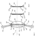
- FIG 8 and FIG 9 demonstrate cross-section views of the switchable cell 220 with actuation members 240, 250 in relaxed state and the switchable cell 220' with actuation members 240', 250' in active state.
- the width of the actuation members 240, 250 along the optical axis 100' in the relaxed state is shown to be narrower the width of the actuation members 240', 250' in active state.
- This is to demonstrate that the corresponding actuation chambers 260, 270 in relaxed state is enlarged into actuation chambers 260', 270' in the active state. In turn, it transforms the refractive daunting surface 380 of the switchable cell 220 into diffraction surface 390 of the switchable cell 220'.
- the formable surface is in contact with aqueous humour in the eye.
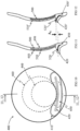
- FIG 10 demonstrates front view of the diffractive switchable contact lens 400.
- the contact lens 400 includes balance 410 at the bottom of the lens to maintain the lens meridional orientation.
- the contact lens 400 also includes the actuation ledge 420 at the bottom of the lens to facilitate interaction with the lower eyelid when viewing down for near focus similar to a performance of an alternating contact lenses.
- the contact lens 400 includes a switchable cell 440 within the optic zone 460 which joints the actuation chamber 450.
- FIG 11 and FIG 12 demonstrate cross-section views of the diffractive switchable contact lens 400 in relaxed state 470, and active state 480 correspondently.
- the switchable cell 440 is located at the lower part of the lens 400 and consists of optical substrate 490 with its back surface forming a part of the back surface or base of the contact lens 400.
- the optical substrate 490 can be made of the same material as the contact lens 400 or a different material bonded to the lens depending if the transparent chamber impermeability can be maintained.
- the guiding surface 500 of the substrate 490 is facing inside the lens with the film 510 free-standing on or bonded to the ridges of the convex shape of the guiding surface 500 in the relaxed state. There is a transparent chamber filled with the matching fluid between the film 510 and guiding surface 500.
- the formable surface of the film 510 is facing a narrow chamber filled with tear medium when the lens 400 is fitting on the eye.
- This chamber acts as the active chamber of the switchable cell 440.
- the actuation chamber 450 is connected to the transparent chamber of the switchable cell 440 for the matching fluid transfer between them to switch between relaxed and active states.
- the actuation chamber 450 is bonded to the actuation level 520 located inside or adjacent to the actuation ledge 420 shown in relaxed state. As the actuation ledge 420 is bent by the lower eyelid pressure when the contact lens wearer looks down for near focus, the actuation level 520 turns.
- the actuation level turn expands the actuation chamber 450 in the relaxed state into actuation chamber 450' in the active state by pulling out the matching fluid from the transparent chamber of the switchable cell 440.
- the film 510' takes the shape of the guiding surface 500 thus modifying the formable surface into a diffraction surface for near focus.
- the transition between the relaxed and active states corresponds to a shift by ⁇ C distance between unturned actuation level 520 and turned actuation level 520'.
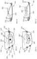
- FIG 13, FIG 14, FIG 15 and FIG 16 depict right half 540 of switchable spectacles to demonstrate a sensing a need for far or near focus.
- the figure 13 shows front view of right half of the spectacles. It consists of frame 650 and switchable spectacle lens 640.
- the IR emitter 550 is installed at one side of the switchable spectacle lens 640.
- An IR sensor 560 is installed on the opposite side of the switchable spectacle lens 640, actually two sensors 560, 570 to provide better sensitivity for sensing.
- Each IR sensor 560 or 570 and IR emitter 550 lie in approximately horizontal planes 620 and 630 correspondently.
- FIG. 13 The depiction of the eye in the figure 13 demonstrates the eye's straight forward gaze for far focus through the switchable spectacle lens 640 with the upper eyelid 580 being in its upper position.
- Figure 14 is upper view of the spectacles half 540 shown on the figure 13 : the IR emission from the IR emitter 600 shown by arrows is reflected off the front surface 590 of the eye ball as shown by solid line 600 and reaches the IR sensor 560 on the opposite side of the frame.
- Figure 15 demonstrates front view of the same switchable spectacles half 540 in the condition when the wearer looks down for near focus with the upper eyelid 580' in its lower position.
- the figure 16 shows the upper view of the figure 15 : IR emission from the IR emitter 550 is fully or partially obstructed by the upper eyelid 580' thus changing the amount of IR radiance received by the IR sensor 560 or both sensors 560, 570.
- the intended reflection from the front surface 590 of the eye ball is shown by the broken line 600'.
- the outcome of the radiation obstruction is a lower electrical signal from the IR sensor which triggers an actuation of the switchable cell from relaxed state for far focus into active state for near focus.
- the figure 15 showed the switchable cell 610 located at a lower part of the switchable spectacle lens 640.
- FIG 17 illustrates the use of switchable cell for low vision application to provide magnification for a visually impaired person. It depicts a spectacle like structure 620 with two pairs of diffractive switchable cells O F +E F for straight forward far vision (subscript F) and O N +E N for down near vision (subscript N).
- a front diffractive switchable cell O F or O N serves as the objective of the Galilean telescope and back diffractive switchable cell E F or E N serves as the eyepiece of the corresponding Galilean telescope.
- High order diffraction can be used to reduce focal lengths in both objective and eyepiece of each pair to shorten the Galilean telescope for its placement onto the spectacle like structure 620.
- FIG. 18 demonstrates Longitudinal Spherical Aberration (LSA) at Far focus by the Diffractive Switchable Ophthalmic Lens (Diffractive Accommodating Lens) in the switching cell relaxed state according to the specifications listed in Tables 1 and 2.
- Table 1 Eye model specifications where Diffractive Accommodating Lens is placed behind the pupil.
- Optical Characteristics Dimension in mm; refractive index Cornea: Anterior surface radius 7.8 Refractive index 1.377 Conic constant (asphericity Q) Nominal Q -0.26 Posterior surface radius (mm) 6.5 Central thickness (mm) 0.55 Aperture stop or pupil position from posterior corneal surface (mm) 3.55 Aqueous refractive index 1.3374 Vitreous refractive index 1.336 Table 2. Relaxed state specifications of the Diffractive Accommodating Lens.
- the LSA for Far focus demonstrates positive spherical aberration for up to about 1 mm from the lens center and negative spherical aberration outside 1 mm distance which is the characteristic of bi-sign asphericity.
- FIG. 19 demonstrates Longitudinal Spherical Aberrations at Near focus by the Diffractive Accommodating Lenses produced at (-1)-order diffraction with switchable cell being in the active state per specifications of Eye model and Diffractive Accommodating Lens in Tables 1 and 2.
- the switchable cell is limited to 4 mm diameter of optical aperture in this example.
- the LSA at Near focus shown on figure 19 manifests significant positive spherical aberration at (-1)-order diffraction to create retinal image from a near object placed not only around 36 cm viewing distance (2.75 D) but through about 27 cm of near viewing distance, i.e. to offer the increased depth of focus at near of about 1 D.
- the increase in depth of focus at near is demonstrated by the corresponding LSA shape which starts at shorter near focus position at the lens center and gradually shifts further away to create a negative slope of the power graph which is most effective for a depth of focus increase.
- Depth of focus or progressive foci feature at near diffraction focus in active state was increased by modifying the phase coefficients for (-1) order diffraction for spherical wavelength to include spherical aberration that spreads the light along the optical axis at the near diffraction focus either to improve near close up or improve intermediate vision capability in addition to providing near.
- a surface position where the optical axis intersects an optical surface is called optical center.
- Each optical surface of the lens has its own optical center which line up on the optical axis in centered optical system.
- Diffractive grooves are defined by their radii from the optical center and diffractive grooves periodicity is defined by differences in consecutive groove radii, i.e. groove periods.
- Central groove means closest to the optical center.
- the periodicity producing the depth of focus increase also has a radius of a peripheral groove that reaches similar magnitude as the groove radius of the same order defined by the Eq.
- Phase coefficients to enhance depth of focus at a diffraction focus can be applied to a monofocal diffractive non-accommodating lens and multifocal diffractive optics where light is split between far and near foci and near image is formed, for example, by (-1)-order diffraction.
- Appropriate phase coefficients can be applied to a multifocal diffractive optic that leads to substantially smaller central (closest to the optical center) diffractive groove radii of the periodic structure for enhanced depth of focus than the central groove radii of the periodic structure that produces spherical wavefront, i.e. per Eq.1.
- the same periodic structure that increases depth of focus reaches a groove radius towards surface periphery that is similar to the groove radius of the same order that produces spherical wavefront, i.e. equivalent to Eq.1.
- the radii of central grooves are defined as starting at the internal side of the annular zone and are also referenced to as “central grooves" or "closest to the optical center grooves”.
Landscapes
- Health & Medical Sciences (AREA)
- Physics & Mathematics (AREA)
- Ophthalmology & Optometry (AREA)
- General Health & Medical Sciences (AREA)
- General Physics & Mathematics (AREA)
- Optics & Photonics (AREA)
- Life Sciences & Earth Sciences (AREA)
- Engineering & Computer Science (AREA)
- Biomedical Technology (AREA)
- Animal Behavior & Ethology (AREA)
- Transplantation (AREA)
- Oral & Maxillofacial Surgery (AREA)
- Public Health (AREA)
- Veterinary Medicine (AREA)
- Heart & Thoracic Surgery (AREA)
- Vascular Medicine (AREA)
- Cardiology (AREA)
- Chemical & Material Sciences (AREA)
- Zoology (AREA)
- Cell Biology (AREA)
- Botany (AREA)
- Chemical Kinetics & Catalysis (AREA)
- Dermatology (AREA)
- Medicinal Chemistry (AREA)
- Epidemiology (AREA)
- Prostheses (AREA)
- Eyeglasses (AREA)
- Mechanical Light Control Or Optical Switches (AREA)
Claims (10)
- Brille mit einem Rahmen, wobei die Brille aufweist:eine schaltbare Linse (640), die an der Brille angebracht ist, wobei die schaltbare Linse (640) dafür ausgelegt ist, ihren Fokus von einer weiten Brennweite zu einer nahen Brennweite zu schalten, wobei die nahe Brennweite kleiner als die große Brennweite ist,einen Infrarotemitter (550), der an einem horizontalen Rand der wenigstens einen schaltbaren Linse (640) angeordnet ist, wobei der Infrarotemitter (550) dafür ausgelegt ist, Infrarotstrahlung auszusenden,einen Infrarotsensor (560, 570), der dafür ausgelegt ist, die Infrarotstrahlung von dem Infrarotemitter (550) zu detektieren,wobei die schaltbare Linse (640) dafür ausgelegt ist, auf ihre weite Brennweite zu schalten, wenn der Infrarotsensor (560,570) eine Intensität an Infrarotstrahlung detektiert, die ausgesandt und von einer Vorderseite des Augapfels eines Trägers reflektiert wurde, wenn der Träger nach vorn schaut, unddadurch gekennzeichnet, dassder Infrarotsensor (560, 570) an einem der wenigstens einen schaltbaren Linse (640) gegenüberliegenden seitlichen Rand angeordnet ist, unddass die schaltbare Linse (640) dafür ausgelegt ist, auf ihre nahe Brennweite zu schalten, wenn der Infrarotsensor (560, 570) eine andere Intensität an Infrarotschaltung detektiert, wenn die Infrarotstrahlung sich bei Reflektion von der Vorderseite des Augapfels des Trägers durch ein oberes Augenlid des Trägers ändert, wenn der Träger nach unten schaut.
- Brille nach Anspruch 1, wobei der Infrarotemitter (550) und der Infrarotsensor (560, 570) in einer gemeinsamen Ebene angeordnet sind.
- Brille nach Anspruch 1 oder 2 mit einem zweiten Infrarotsensor (570), der in einer anderen Ebene als der gemeinsamen Ebene angeordnet ist, wobei der zweite Infrarotsensor (570) an dem Rand angeordnet ist, wo der erste Infrarotsensor (560) angeordnet ist.
- Brille nach einem der vorstehenden Ansprüche, wobei der Infrarotsensor (560, 570) dafür ausgelegt ist, die Intensität oder die unterschiedliche Intensität der von dem Infrarotemitter (550) ausgesandten Infrarotstrahlung zu detektieren, nachdem sie von der Vorderseite des Augapfels des Trägers reflektiert wurde, wobei die schaltbare Linse (640) ihre Brennweite auf die entsprechende nahe oder weite Brennweite schaltet.
- Brille nach einem der vorstehenden Ansprüche, wobei die Brille eine horizontale Ebene definiert, die im Wesentlichen durch einen Bügel und eine Brücke der Brille verläuft.
- Brille nach Anspruch 5, wobei der Infrarotemitter (550) und der Infrarotsensor (560) in einer zweiten horizontalen Ebene angeordnet sind, die parallel zu der horizontalen Ebene verläuft.
- Brille nach Anspruch 6 mit einem zweiten Infrarotsensor (570), der in einer anderen horizontalen Ebene als der zweiten horizontalen Ebene und an demselben Rand, wo der Infrarotsensor (560) angeordnet ist, angeordnet ist.
- Brille nach Anspruch 5, wobei die schaltbare Linse zwischen der nahen und weiten Brennweite in Abhängigkeit von einer Änderung der Intensität der Infrarotstrahlung schaltet, die von dem Infrarotemitter (550) ausgesandt und von dem Infrarotsensor (560, 570) detektiert wird.
- Brille nach einem der vorstehenden Ansprüche, wobei die unterschiedliche Intensität eine reduzierte Intensität im Vergleich zu der Intensität ist.
- Brille nach Anspruch 9, wobei die reduzierte Intensität null ist.
Applications Claiming Priority (5)
| Application Number | Priority Date | Filing Date | Title |
|---|---|---|---|
| US201261587813P | 2012-01-18 | 2012-01-18 | |
| US201261620588P | 2012-04-05 | 2012-04-05 | |
| US13/626,118 US9364319B2 (en) | 2012-09-25 | 2012-09-25 | Refractive-diffractive switchable optical element |
| PCT/US2012/057253 WO2013109315A2 (en) | 2012-01-18 | 2012-09-26 | Refractive-diffractive switchable optical element |
| EP12891429.8A EP2820465B1 (de) | 2012-01-18 | 2012-09-26 | Refraktiv-diffraktives schaltbares optisches element |
Related Parent Applications (2)
| Application Number | Title | Priority Date | Filing Date |
|---|---|---|---|
| EP12891429.8A Division EP2820465B1 (de) | 2012-01-18 | 2012-09-26 | Refraktiv-diffraktives schaltbares optisches element |
| EP12891429.8A Division-Into EP2820465B1 (de) | 2012-01-18 | 2012-09-26 | Refraktiv-diffraktives schaltbares optisches element |
Publications (2)
| Publication Number | Publication Date |
|---|---|
| EP3594735A1 EP3594735A1 (de) | 2020-01-15 |
| EP3594735B1 true EP3594735B1 (de) | 2024-09-18 |
Family
ID=48799795
Family Applications (2)
| Application Number | Title | Priority Date | Filing Date |
|---|---|---|---|
| EP19187700.0A Active EP3594735B1 (de) | 2012-01-18 | 2012-09-26 | Refraktiv-diffraktives schaltbares optisches element |
| EP12891429.8A Active EP2820465B1 (de) | 2012-01-18 | 2012-09-26 | Refraktiv-diffraktives schaltbares optisches element |
Family Applications After (1)
| Application Number | Title | Priority Date | Filing Date |
|---|---|---|---|
| EP12891429.8A Active EP2820465B1 (de) | 2012-01-18 | 2012-09-26 | Refraktiv-diffraktives schaltbares optisches element |
Country Status (3)
| Country | Link |
|---|---|
| EP (2) | EP3594735B1 (de) |
| CA (1) | CA2869850C (de) |
| WO (1) | WO2013109315A2 (de) |
Families Citing this family (5)
| Publication number | Priority date | Publication date | Assignee | Title |
|---|---|---|---|---|
| WO2015095891A1 (en) | 2013-12-20 | 2015-06-25 | Onefocus Vision, Llc | Fluidic module for accomodating soft contact lens |
| US10302968B2 (en) | 2013-01-28 | 2019-05-28 | Onefocus Vision, Inc. | Fluidic module for accommodating soft contact lens |
| EP3174501A4 (de) * | 2014-07-31 | 2018-07-25 | Onefocus Vision, LLC | Opfergiessverfahren für akkommodationskontaktlinse |
| EP4651830A1 (de) * | 2023-01-17 | 2025-11-26 | Amo Groningen B.V. | Linsen mit änderung der optischen leistung als reaktion auf einen akkommodativen stimulus |
| KR102690520B1 (ko) * | 2023-12-21 | 2024-08-05 | 한국기계연구원 | 인공 수정체 및 이의 제조방법 |
Family Cites Families (21)
| Publication number | Priority date | Publication date | Assignee | Title |
|---|---|---|---|---|
| US3379885A (en) * | 1966-03-01 | 1968-04-23 | Nasa Usa | Sight switch using an infrared source and sensor |
| US3689135A (en) * | 1971-01-26 | 1972-09-05 | Laurence R Young | Method for monitoring movement of a subject{40 s eyes |
| US4181408A (en) * | 1977-12-05 | 1980-01-01 | Senders John W | Vision compensation |
| US4435856A (en) * | 1982-04-14 | 1984-03-13 | Esperance Francis A L | Bifocal intraocular lens structure and spectacle actuation frame |
| US4731078A (en) * | 1985-08-21 | 1988-03-15 | Kingston Technologies Limited Partnership | Intraocular lens |
| GB2183059B (en) * | 1985-11-05 | 1989-09-27 | Michel Treisman | Suspension system for a flexible optical membrane |
| US4932966A (en) * | 1988-08-15 | 1990-06-12 | Storz Instrument Company | Accommodating intraocular lens |
| US5182585A (en) * | 1991-09-26 | 1993-01-26 | The Arizona Carbon Foil Company, Inc. | Eyeglasses with controllable refracting power |
| US6445509B1 (en) * | 1999-08-16 | 2002-09-03 | Ray Marvin Alden | Variable fresnel type structures and process |
| US5956183A (en) * | 1998-05-26 | 1999-09-21 | Epstein; Saul | Field-customizable variable focal length lens |
| US6619799B1 (en) * | 1999-07-02 | 2003-09-16 | E-Vision, Llc | Optical lens system with electro-active lens having alterably different focal lengths |
| US6730123B1 (en) * | 2000-06-22 | 2004-05-04 | Proteus Vision, Llc | Adjustable intraocular lens |
| EP1563337A4 (de) * | 2002-11-20 | 2006-05-24 | Powervision | Linsensystem und verfahren zur leistungseinstellung |
| WO2004054471A2 (en) * | 2002-12-12 | 2004-07-01 | Powervision | Accommodating intraocular lens system and method |
| US20050038510A1 (en) * | 2003-08-13 | 2005-02-17 | Valdemar Portney | Multi-piece intraocular lens assembly and method of manufacturing same |
| US20070032866A1 (en) * | 2005-08-05 | 2007-02-08 | Valdemar Portney | Accommodating diffractive intraocular lens |
| US8619362B2 (en) | 2006-08-01 | 2013-12-31 | Valdemar Portney | Multifocal diffractive ophthalmic lens with multifocal base surface |
| AR064985A1 (es) | 2007-01-22 | 2009-05-06 | E Vision Llc | Lente electroactivo flexible |
| US8523354B2 (en) * | 2008-04-11 | 2013-09-03 | Pixeloptics Inc. | Electro-active diffractive lens and method for making the same |
| GB201006913D0 (en) * | 2010-04-26 | 2010-06-09 | Taylor Richard | Refractive eyewear |
| TW201234072A (en) * | 2010-11-01 | 2012-08-16 | Pixeloptics Inc | Dynamic changeable focus contact and intraocular lens |
-
2012
- 2012-09-26 EP EP19187700.0A patent/EP3594735B1/de active Active
- 2012-09-26 EP EP12891429.8A patent/EP2820465B1/de active Active
- 2012-09-26 WO PCT/US2012/057253 patent/WO2013109315A2/en not_active Ceased
- 2012-09-26 CA CA2869850A patent/CA2869850C/en active Active
Also Published As
| Publication number | Publication date |
|---|---|
| EP3594735A1 (de) | 2020-01-15 |
| CA2869850C (en) | 2017-03-14 |
| EP2820465A4 (de) | 2016-03-23 |
| CA2869850A1 (en) | 2013-07-25 |
| EP2820465B1 (de) | 2019-11-06 |
| WO2013109315A3 (en) | 2014-05-08 |
| EP2820465A2 (de) | 2015-01-07 |
| WO2013109315A2 (en) | 2013-07-25 |
Similar Documents
| Publication | Publication Date | Title |
|---|---|---|
| US9927634B2 (en) | Switchable spectacles | |
| US10531950B2 (en) | Intraocular lens having an extended depth of focus | |
| EP1982230B1 (de) | Pseudo-akkommodations-iol mit mehrfachen brechungsmustern | |
| EP2254510B1 (de) | Akkommodative iol mit dynamischer sphärischer aberration | |
| EP1982229B1 (de) | Pseudo-akkommodative intraokularlinse mit diffraktionszonen mit unterschiedlichen bereichen | |
| EP2403429B1 (de) | Multizonale linse mit erweiterter fokustiefe | |
| US10265162B2 (en) | Multizonal lens with enhanced performance | |
| CN107072779B (zh) | 具有扩展的景深和增强的远距视力的眼科植入物 | |
| EP2407816A1 (de) | Zonendiffraktive Intraokularlinsen mit Mehrfachfokus | |
| US20130035760A1 (en) | Switchable diffractive accommodating lens | |
| EP1563337A2 (de) | Linsensystem und verfahren zur leistungseinstellung | |
| EP2820465B1 (de) | Refraktiv-diffraktives schaltbares optisches element | |
| US20250073020A1 (en) | Ophthalmic lenses with first and second portions | |
| HK1162687A (en) | Zonal diffractive trifocal intraocular lenses | |
| HK1162688A (en) | Zonal diffractive multifocal intraocular lenses | |
| HK1241686B (zh) | 具有扩展的景深和增强的远距视力的眼科植入物 |
Legal Events
| Date | Code | Title | Description |
|---|---|---|---|
| PUAI | Public reference made under article 153(3) epc to a published international application that has entered the european phase |
Free format text: ORIGINAL CODE: 0009012 |
|
| STAA | Information on the status of an ep patent application or granted ep patent |
Free format text: STATUS: THE APPLICATION HAS BEEN PUBLISHED |
|
| AC | Divisional application: reference to earlier application |
Ref document number: 2820465 Country of ref document: EP Kind code of ref document: P |
|
| AK | Designated contracting states |
Kind code of ref document: A1 Designated state(s): AL AT BE BG CH CY CZ DE DK EE ES FI FR GB GR HR HU IE IS IT LI LT LU LV MC MK MT NL NO PL PT RO RS SE SI SK SM TR |
|
| STAA | Information on the status of an ep patent application or granted ep patent |
Free format text: STATUS: REQUEST FOR EXAMINATION WAS MADE |
|
| 17P | Request for examination filed |
Effective date: 20200714 |
|
| RBV | Designated contracting states (corrected) |
Designated state(s): AL AT BE BG CH CY CZ DE DK EE ES FI FR GB GR HR HU IE IS IT LI LT LU LV MC MK MT NL NO PL PT RO RS SE SI SK SM TR |
|
| STAA | Information on the status of an ep patent application or granted ep patent |
Free format text: STATUS: EXAMINATION IS IN PROGRESS |
|
| 17Q | First examination report despatched |
Effective date: 20221006 |
|
| GRAP | Despatch of communication of intention to grant a patent |
Free format text: ORIGINAL CODE: EPIDOSNIGR1 |
|
| STAA | Information on the status of an ep patent application or granted ep patent |
Free format text: STATUS: GRANT OF PATENT IS INTENDED |
|
| INTG | Intention to grant announced |
Effective date: 20240429 |
|
| GRAS | Grant fee paid |
Free format text: ORIGINAL CODE: EPIDOSNIGR3 |
|
| GRAA | (expected) grant |
Free format text: ORIGINAL CODE: 0009210 |
|
| STAA | Information on the status of an ep patent application or granted ep patent |
Free format text: STATUS: THE PATENT HAS BEEN GRANTED |
|
| AC | Divisional application: reference to earlier application |
Ref document number: 2820465 Country of ref document: EP Kind code of ref document: P |
|
| AK | Designated contracting states |
Kind code of ref document: B1 Designated state(s): AL AT BE BG CH CY CZ DE DK EE ES FI FR GB GR HR HU IE IS IT LI LT LU LV MC MK MT NL NO PL PT RO RS SE SI SK SM TR |
|
| REG | Reference to a national code |
Ref country code: GB Ref legal event code: FG4D |
|
| REG | Reference to a national code |
Ref country code: CH Ref legal event code: EP |
|
| REG | Reference to a national code |
Ref country code: DE Ref legal event code: R096 Ref document number: 602012081081 Country of ref document: DE |
|
| REG | Reference to a national code |
Ref country code: IE Ref legal event code: FG4D |
|
| REG | Reference to a national code |
Ref country code: LT Ref legal event code: MG9D |
|
| PG25 | Lapsed in a contracting state [announced via postgrant information from national office to epo] |
Ref country code: NO Free format text: LAPSE BECAUSE OF FAILURE TO SUBMIT A TRANSLATION OF THE DESCRIPTION OR TO PAY THE FEE WITHIN THE PRESCRIBED TIME-LIMIT Effective date: 20241218 |
|
| PG25 | Lapsed in a contracting state [announced via postgrant information from national office to epo] |
Ref country code: GR Free format text: LAPSE BECAUSE OF FAILURE TO SUBMIT A TRANSLATION OF THE DESCRIPTION OR TO PAY THE FEE WITHIN THE PRESCRIBED TIME-LIMIT Effective date: 20241219 Ref country code: FI Free format text: LAPSE BECAUSE OF FAILURE TO SUBMIT A TRANSLATION OF THE DESCRIPTION OR TO PAY THE FEE WITHIN THE PRESCRIBED TIME-LIMIT Effective date: 20240918 |
|
| PG25 | Lapsed in a contracting state [announced via postgrant information from national office to epo] |
Ref country code: BG Free format text: LAPSE BECAUSE OF FAILURE TO SUBMIT A TRANSLATION OF THE DESCRIPTION OR TO PAY THE FEE WITHIN THE PRESCRIBED TIME-LIMIT Effective date: 20240918 |
|
| PG25 | Lapsed in a contracting state [announced via postgrant information from national office to epo] |
Ref country code: LV Free format text: LAPSE BECAUSE OF FAILURE TO SUBMIT A TRANSLATION OF THE DESCRIPTION OR TO PAY THE FEE WITHIN THE PRESCRIBED TIME-LIMIT Effective date: 20240918 |
|
| PG25 | Lapsed in a contracting state [announced via postgrant information from national office to epo] |
Ref country code: HR Free format text: LAPSE BECAUSE OF FAILURE TO SUBMIT A TRANSLATION OF THE DESCRIPTION OR TO PAY THE FEE WITHIN THE PRESCRIBED TIME-LIMIT Effective date: 20240918 |
|
| REG | Reference to a national code |
Ref country code: NL Ref legal event code: MP Effective date: 20240918 |
|
| PG25 | Lapsed in a contracting state [announced via postgrant information from national office to epo] |
Ref country code: RS Free format text: LAPSE BECAUSE OF FAILURE TO SUBMIT A TRANSLATION OF THE DESCRIPTION OR TO PAY THE FEE WITHIN THE PRESCRIBED TIME-LIMIT Effective date: 20241218 |
|
| PG25 | Lapsed in a contracting state [announced via postgrant information from national office to epo] |
Ref country code: RS Free format text: LAPSE BECAUSE OF FAILURE TO SUBMIT A TRANSLATION OF THE DESCRIPTION OR TO PAY THE FEE WITHIN THE PRESCRIBED TIME-LIMIT Effective date: 20241218 Ref country code: NO Free format text: LAPSE BECAUSE OF FAILURE TO SUBMIT A TRANSLATION OF THE DESCRIPTION OR TO PAY THE FEE WITHIN THE PRESCRIBED TIME-LIMIT Effective date: 20241218 Ref country code: LV Free format text: LAPSE BECAUSE OF FAILURE TO SUBMIT A TRANSLATION OF THE DESCRIPTION OR TO PAY THE FEE WITHIN THE PRESCRIBED TIME-LIMIT Effective date: 20240918 Ref country code: HR Free format text: LAPSE BECAUSE OF FAILURE TO SUBMIT A TRANSLATION OF THE DESCRIPTION OR TO PAY THE FEE WITHIN THE PRESCRIBED TIME-LIMIT Effective date: 20240918 Ref country code: GR Free format text: LAPSE BECAUSE OF FAILURE TO SUBMIT A TRANSLATION OF THE DESCRIPTION OR TO PAY THE FEE WITHIN THE PRESCRIBED TIME-LIMIT Effective date: 20241219 Ref country code: FI Free format text: LAPSE BECAUSE OF FAILURE TO SUBMIT A TRANSLATION OF THE DESCRIPTION OR TO PAY THE FEE WITHIN THE PRESCRIBED TIME-LIMIT Effective date: 20240918 Ref country code: BG Free format text: LAPSE BECAUSE OF FAILURE TO SUBMIT A TRANSLATION OF THE DESCRIPTION OR TO PAY THE FEE WITHIN THE PRESCRIBED TIME-LIMIT Effective date: 20240918 |
|
| REG | Reference to a national code |
Ref country code: AT Ref legal event code: MK05 Ref document number: 1725189 Country of ref document: AT Kind code of ref document: T Effective date: 20240918 |
|
| PG25 | Lapsed in a contracting state [announced via postgrant information from national office to epo] |
Ref country code: NL Free format text: LAPSE BECAUSE OF FAILURE TO SUBMIT A TRANSLATION OF THE DESCRIPTION OR TO PAY THE FEE WITHIN THE PRESCRIBED TIME-LIMIT Effective date: 20240918 |
|
| PG25 | Lapsed in a contracting state [announced via postgrant information from national office to epo] |
Ref country code: IS Free format text: LAPSE BECAUSE OF FAILURE TO SUBMIT A TRANSLATION OF THE DESCRIPTION OR TO PAY THE FEE WITHIN THE PRESCRIBED TIME-LIMIT Effective date: 20250118 Ref country code: PT Free format text: LAPSE BECAUSE OF FAILURE TO SUBMIT A TRANSLATION OF THE DESCRIPTION OR TO PAY THE FEE WITHIN THE PRESCRIBED TIME-LIMIT Effective date: 20250120 |
|
| PG25 | Lapsed in a contracting state [announced via postgrant information from national office to epo] |
Ref country code: RO Free format text: LAPSE BECAUSE OF FAILURE TO SUBMIT A TRANSLATION OF THE DESCRIPTION OR TO PAY THE FEE WITHIN THE PRESCRIBED TIME-LIMIT Effective date: 20240918 Ref country code: SM Free format text: LAPSE BECAUSE OF FAILURE TO SUBMIT A TRANSLATION OF THE DESCRIPTION OR TO PAY THE FEE WITHIN THE PRESCRIBED TIME-LIMIT Effective date: 20240918 |
|
| PG25 | Lapsed in a contracting state [announced via postgrant information from national office to epo] |
Ref country code: ES Free format text: LAPSE BECAUSE OF FAILURE TO SUBMIT A TRANSLATION OF THE DESCRIPTION OR TO PAY THE FEE WITHIN THE PRESCRIBED TIME-LIMIT Effective date: 20240918 |
|
| PG25 | Lapsed in a contracting state [announced via postgrant information from national office to epo] |
Ref country code: AT Free format text: LAPSE BECAUSE OF FAILURE TO SUBMIT A TRANSLATION OF THE DESCRIPTION OR TO PAY THE FEE WITHIN THE PRESCRIBED TIME-LIMIT Effective date: 20240918 Ref country code: EE Free format text: LAPSE BECAUSE OF FAILURE TO SUBMIT A TRANSLATION OF THE DESCRIPTION OR TO PAY THE FEE WITHIN THE PRESCRIBED TIME-LIMIT Effective date: 20240918 |
|
| PG25 | Lapsed in a contracting state [announced via postgrant information from national office to epo] |
Ref country code: CZ Free format text: LAPSE BECAUSE OF FAILURE TO SUBMIT A TRANSLATION OF THE DESCRIPTION OR TO PAY THE FEE WITHIN THE PRESCRIBED TIME-LIMIT Effective date: 20240918 Ref country code: PL Free format text: LAPSE BECAUSE OF FAILURE TO SUBMIT A TRANSLATION OF THE DESCRIPTION OR TO PAY THE FEE WITHIN THE PRESCRIBED TIME-LIMIT Effective date: 20240918 |
|
| PG25 | Lapsed in a contracting state [announced via postgrant information from national office to epo] |
Ref country code: SK Free format text: LAPSE BECAUSE OF FAILURE TO SUBMIT A TRANSLATION OF THE DESCRIPTION OR TO PAY THE FEE WITHIN THE PRESCRIBED TIME-LIMIT Effective date: 20240918 Ref country code: IT Free format text: LAPSE BECAUSE OF FAILURE TO SUBMIT A TRANSLATION OF THE DESCRIPTION OR TO PAY THE FEE WITHIN THE PRESCRIBED TIME-LIMIT Effective date: 20240918 |
|
| REG | Reference to a national code |
Ref country code: CH Ref legal event code: PL |
|
| PG25 | Lapsed in a contracting state [announced via postgrant information from national office to epo] |
Ref country code: LU Free format text: LAPSE BECAUSE OF NON-PAYMENT OF DUE FEES Effective date: 20240926 |
|
| REG | Reference to a national code |
Ref country code: DE Ref legal event code: R097 Ref document number: 602012081081 Country of ref document: DE |
|
| PG25 | Lapsed in a contracting state [announced via postgrant information from national office to epo] |
Ref country code: MC Free format text: LAPSE BECAUSE OF FAILURE TO SUBMIT A TRANSLATION OF THE DESCRIPTION OR TO PAY THE FEE WITHIN THE PRESCRIBED TIME-LIMIT Effective date: 20240918 |
|
| PG25 | Lapsed in a contracting state [announced via postgrant information from national office to epo] |
Ref country code: DK Free format text: LAPSE BECAUSE OF FAILURE TO SUBMIT A TRANSLATION OF THE DESCRIPTION OR TO PAY THE FEE WITHIN THE PRESCRIBED TIME-LIMIT Effective date: 20240918 |
|
| REG | Reference to a national code |
Ref country code: BE Ref legal event code: MM Effective date: 20240930 |
|
| PG25 | Lapsed in a contracting state [announced via postgrant information from national office to epo] |
Ref country code: BE Free format text: LAPSE BECAUSE OF NON-PAYMENT OF DUE FEES Effective date: 20240930 |
|
| PG25 | Lapsed in a contracting state [announced via postgrant information from national office to epo] |
Ref country code: CH Free format text: LAPSE BECAUSE OF NON-PAYMENT OF DUE FEES Effective date: 20240930 |
|
| PLBE | No opposition filed within time limit |
Free format text: ORIGINAL CODE: 0009261 |
|
| STAA | Information on the status of an ep patent application or granted ep patent |
Free format text: STATUS: NO OPPOSITION FILED WITHIN TIME LIMIT |
|
| PG25 | Lapsed in a contracting state [announced via postgrant information from national office to epo] |
Ref country code: IE Free format text: LAPSE BECAUSE OF NON-PAYMENT OF DUE FEES Effective date: 20240926 |
|
| 26N | No opposition filed |
Effective date: 20250619 |
|
| GBPC | Gb: european patent ceased through non-payment of renewal fee |
Effective date: 20241218 |
|
| PG25 | Lapsed in a contracting state [announced via postgrant information from national office to epo] |
Ref country code: SE Free format text: LAPSE BECAUSE OF FAILURE TO SUBMIT A TRANSLATION OF THE DESCRIPTION OR TO PAY THE FEE WITHIN THE PRESCRIBED TIME-LIMIT Effective date: 20240918 |
|
| PGFP | Annual fee paid to national office [announced via postgrant information from national office to epo] |
Ref country code: DE Payment date: 20250929 Year of fee payment: 14 |
|
| PG25 | Lapsed in a contracting state [announced via postgrant information from national office to epo] |
Ref country code: GB Free format text: LAPSE BECAUSE OF NON-PAYMENT OF DUE FEES Effective date: 20241218 |
|
| PGFP | Annual fee paid to national office [announced via postgrant information from national office to epo] |
Ref country code: FR Payment date: 20250925 Year of fee payment: 14 |
|
| PG25 | Lapsed in a contracting state [announced via postgrant information from national office to epo] |
Ref country code: CY Free format text: LAPSE BECAUSE OF FAILURE TO SUBMIT A TRANSLATION OF THE DESCRIPTION OR TO PAY THE FEE WITHIN THE PRESCRIBED TIME-LIMIT; INVALID AB INITIO Effective date: 20120926 |
|
| PG25 | Lapsed in a contracting state [announced via postgrant information from national office to epo] |
Ref country code: HU Free format text: LAPSE BECAUSE OF FAILURE TO SUBMIT A TRANSLATION OF THE DESCRIPTION OR TO PAY THE FEE WITHIN THE PRESCRIBED TIME-LIMIT; INVALID AB INITIO Effective date: 20120926 |