EP3594545B1 - Schlauchtrommelanordnung - Google Patents
Schlauchtrommelanordnung Download PDFInfo
- Publication number
- EP3594545B1 EP3594545B1 EP19174208.9A EP19174208A EP3594545B1 EP 3594545 B1 EP3594545 B1 EP 3594545B1 EP 19174208 A EP19174208 A EP 19174208A EP 3594545 B1 EP3594545 B1 EP 3594545B1
- Authority
- EP
- European Patent Office
- Prior art keywords
- hose
- drum
- heating means
- arrangement according
- axis
- Prior art date
- Legal status (The legal status is an assumption and is not a legal conclusion. Google has not performed a legal analysis and makes no representation as to the accuracy of the status listed.)
- Not-in-force
Links
Images


Classifications
-
- F—MECHANICAL ENGINEERING; LIGHTING; HEATING; WEAPONS; BLASTING
- F16—ENGINEERING ELEMENTS AND UNITS; GENERAL MEASURES FOR PRODUCING AND MAINTAINING EFFECTIVE FUNCTIONING OF MACHINES OR INSTALLATIONS; THERMAL INSULATION IN GENERAL
- F16L—PIPES; JOINTS OR FITTINGS FOR PIPES; SUPPORTS FOR PIPES, CABLES OR PROTECTIVE TUBING; MEANS FOR THERMAL INSULATION IN GENERAL
- F16L11/00—Hoses, i.e. flexible pipes
- F16L11/04—Hoses, i.e. flexible pipes made of rubber or flexible plastics
- F16L11/12—Hoses, i.e. flexible pipes made of rubber or flexible plastics with arrangements for particular purposes, e.g. specially profiled, with protecting layer, heated, electrically conducting
-
- B—PERFORMING OPERATIONS; TRANSPORTING
- B65—CONVEYING; PACKING; STORING; HANDLING THIN OR FILAMENTARY MATERIAL
- B65H—HANDLING THIN OR FILAMENTARY MATERIAL, e.g. SHEETS, WEBS, CABLES
- B65H75/00—Storing webs, tapes, or filamentary material, e.g. on reels
- B65H75/02—Cores, formers, supports, or holders for coiled, wound, or folded material, e.g. reels, spindles, bobbins, cop tubes, cans, mandrels or chucks
- B65H75/04—Kinds or types
- B65H75/08—Kinds or types of circular or polygonal cross-section
- B65H75/14—Kinds or types of circular or polygonal cross-section with two end flanges
-
- B—PERFORMING OPERATIONS; TRANSPORTING
- B65—CONVEYING; PACKING; STORING; HANDLING THIN OR FILAMENTARY MATERIAL
- B65H—HANDLING THIN OR FILAMENTARY MATERIAL, e.g. SHEETS, WEBS, CABLES
- B65H75/00—Storing webs, tapes, or filamentary material, e.g. on reels
- B65H75/02—Cores, formers, supports, or holders for coiled, wound, or folded material, e.g. reels, spindles, bobbins, cop tubes, cans, mandrels or chucks
- B65H75/34—Cores, formers, supports, or holders for coiled, wound, or folded material, e.g. reels, spindles, bobbins, cop tubes, cans, mandrels or chucks specially adapted or mounted for storing and repeatedly paying-out and re-storing lengths of material provided for particular purposes, e.g. anchored hoses, power cables
- B65H75/38—Cores, formers, supports, or holders for coiled, wound, or folded material, e.g. reels, spindles, bobbins, cop tubes, cans, mandrels or chucks specially adapted or mounted for storing and repeatedly paying-out and re-storing lengths of material provided for particular purposes, e.g. anchored hoses, power cables involving the use of a core or former internal to, and supporting, a stored package of material
- B65H75/44—Constructional details
- B65H75/4478—Constructional details relating to handling of fluids
-
- F—MECHANICAL ENGINEERING; LIGHTING; HEATING; WEAPONS; BLASTING
- F16—ENGINEERING ELEMENTS AND UNITS; GENERAL MEASURES FOR PRODUCING AND MAINTAINING EFFECTIVE FUNCTIONING OF MACHINES OR INSTALLATIONS; THERMAL INSULATION IN GENERAL
- F16L—PIPES; JOINTS OR FITTINGS FOR PIPES; SUPPORTS FOR PIPES, CABLES OR PROTECTIVE TUBING; MEANS FOR THERMAL INSULATION IN GENERAL
- F16L3/00—Supports for pipes, cables or protective tubing, e.g. hangers, holders, clamps, cleats, clips, brackets
- F16L3/01—Supports for pipes, cables or protective tubing, e.g. hangers, holders, clamps, cleats, clips, brackets for supporting or guiding the pipes, cables or protective tubing, between relatively movable points, e.g. movable channels
- F16L3/012—Supports for pipes, cables or protective tubing, e.g. hangers, holders, clamps, cleats, clips, brackets for supporting or guiding the pipes, cables or protective tubing, between relatively movable points, e.g. movable channels using reels
-
- F—MECHANICAL ENGINEERING; LIGHTING; HEATING; WEAPONS; BLASTING
- F16—ENGINEERING ELEMENTS AND UNITS; GENERAL MEASURES FOR PRODUCING AND MAINTAINING EFFECTIVE FUNCTIONING OF MACHINES OR INSTALLATIONS; THERMAL INSULATION IN GENERAL
- F16L—PIPES; JOINTS OR FITTINGS FOR PIPES; SUPPORTS FOR PIPES, CABLES OR PROTECTIVE TUBING; MEANS FOR THERMAL INSULATION IN GENERAL
- F16L53/00—Heating of pipes or pipe systems; Cooling of pipes or pipe systems
- F16L53/30—Heating of pipes or pipe systems
- F16L53/35—Ohmic-resistance heating
-
- F—MECHANICAL ENGINEERING; LIGHTING; HEATING; WEAPONS; BLASTING
- F16—ENGINEERING ELEMENTS AND UNITS; GENERAL MEASURES FOR PRODUCING AND MAINTAINING EFFECTIVE FUNCTIONING OF MACHINES OR INSTALLATIONS; THERMAL INSULATION IN GENERAL
- F16L—PIPES; JOINTS OR FITTINGS FOR PIPES; SUPPORTS FOR PIPES, CABLES OR PROTECTIVE TUBING; MEANS FOR THERMAL INSULATION IN GENERAL
- F16L53/00—Heating of pipes or pipe systems; Cooling of pipes or pipe systems
- F16L53/30—Heating of pipes or pipe systems
- F16L53/35—Ohmic-resistance heating
- F16L53/38—Ohmic-resistance heating using elongate electric heating elements, e.g. wires or ribbons
-
- B—PERFORMING OPERATIONS; TRANSPORTING
- B65—CONVEYING; PACKING; STORING; HANDLING THIN OR FILAMENTARY MATERIAL
- B65H—HANDLING THIN OR FILAMENTARY MATERIAL, e.g. SHEETS, WEBS, CABLES
- B65H2701/00—Handled material; Storage means
- B65H2701/30—Handled filamentary material
- B65H2701/33—Hollow or hose-like material
-
- B—PERFORMING OPERATIONS; TRANSPORTING
- B65—CONVEYING; PACKING; STORING; HANDLING THIN OR FILAMENTARY MATERIAL
- B65H—HANDLING THIN OR FILAMENTARY MATERIAL, e.g. SHEETS, WEBS, CABLES
- B65H2701/00—Handled material; Storage means
- B65H2701/50—Storage means for webs, tapes, or filamentary material
- B65H2701/52—Integration of elements inside the core or reel
- B65H2701/528—Heating or cooling devices
Definitions
- the invention relates to a hose reel assembly having the features in patent claim 1.
- Hose reels are used for orderly winding and unwinding of hoses. Hose reels can only be used to a limited extent at sub-zero temperatures because there is a risk that water in the hose will freeze if the fluid flow is interrupted. Heating from the outside is hardly possible over the entire length of a coiled hose and is very energy-consuming. Practically the entire hose reel would have to be stored in a heated room. In the EP 2 499 904 B1 it is proposed to heat the hose not from the outside but from the inside by introducing an electrical heating medium into the hose. The electrical heating means is supplied with energy via a slip ring arrangement. If the flow rate is to be kept constant, the hose diameter must be increased.
- the EP 1 329 660 A2 discloses a flexible, multi-layer, heatable hose for the passage of a liquid.
- the hose is flexible and the heating conductor is embedded in the hose jacket in a spiral shape.
- the electrical conductor is to be protected by the sheath to ensure electrical insulation so that it is not affected by corrosion or damage Short-circuit can occur as a result of penetrating moisture.
- Such a hose is used in particular as a flexible, heatable pressure hose for motor vehicles.
- the ends of the hose are stationary so that the electrical heating conductor can also be connected to a voltage source required to operate the heating conductor via stationary connections at each end.
- With a hose drum at least one end of the hose can be displaced, either because it rotates with the hose drum or because the other end of the hose is also displaced when the hose drum is stationary. Stationary feed-in of electricity is not possible.
- the U.S. 3,314,562 discloses a vacuum device for lifting objects in which an electrical conductor is intended to run inside a hose to save another cable reel and to protect the cable in the hose.
- the cable In the area of the hose drum, the cable is electrically connected via a slip ring transmitter.
- the invention is based on the object of demonstrating a hose reel arrangement which can also be used in cold weather and in which large discharge volumes can be realized with small hose diameters.
- the hose drum arrangement according to the invention has a drum body with a drum axis and drum body disks arranged on the drum axis.
- the drum body discs limit the winding width. It can be a hose reel arrangement that winds spirally or cylindrically. Combinations are possible.
- a spiral winding can, for example, be carried out in two rows next to each other.
- a cylindrical winding can also be carried out in several layers one on top of the other.
- the drum body is rotatably mounted on a drum axis.
- the reel axle supports the hose and the reel body pulleys. Depending on the dimensioning of the hose reel arrangement, one or two bearings are required for the reel axis.
- the drum axis is at least partially designed as a fluid line to which the hose to be wound up is connected.
- the drum axis In the case of cylindrically winding hose drum arrangements, the drum axis is comparatively long. In this case it is not necessary to form the entire drum axis as a fluid line. In spirally wound hose reel assemblies, the reel axis is short. A single bearing is sufficient.
- a rotary leadthrough with a non-rotatable supply line is then connected to the rotatable drum axis on the one hand and the hose on the other. It is guided radially outwards over a winding drum located between the drum body disks.
- a slip ring arrangement is arranged next to the rotary union on the drum axis. Electrical energy can be fed into a heating medium via the slip ring arrangement.
- the heating means is electrically connected to the slip ring arrangement.
- the heating medium is embedded in the jacket of the hose. Embedding has the advantage that the inner cross-section of the hose remains completely free. There are no turbulences within the hose and thus no flow losses caused by the heating conductor. This in turn means that the outflow volume is not reduced.
- hoses with smaller inner diameters can be used with the same flow rate. Smaller hose diameters also mean smaller hose reel assemblies. As a result, the hose reel arrangements require less installation space. Even retrofitting of existing hose reels is possible.
- the heating means in the hose wall is preferably a heating tape. This heating tape is able to keep the water in the hose above 0°C.
- the slip ring assembly is located outside of the hose winding area.
- the hose with the heating means embedded in the jacket is therefore arranged on the side of the drum body disks facing away from the slip ring arrangement and is connected there to the drum axis.
- the spool disc interferes with the connection of the heating medium to the slip ring assembly.
- the heating means is guided out of the hose radially outwards on one side of a drum body disk.
- the heating medium is now continued on the outside along the axis of the drum and passes through an opening in the disk of the drum body.
- the heating medium is isolated from its surroundings in this area.
- the heating medium does not have to emit any heat in its course from the slip ring arrangement to the entry into the hose.
- the heating means can also be designed as a wire with a corresponding cross-section in this transition area, so that no thermal stresses arise in the area of the drum body disks.
- the heating medium can be guided from the hose to the rotating part of the slip ring arrangement in a very space-saving manner and without great effort.
- it is not necessary to secure the heating medium against the flow force in the hose using a traction mechanism. There is no cross-sectional reduction of the inner hose diameter.
- the heating medium can be routed through just one drum body disk (cylindrical hose drum) or through both drum body disks (spirally wound hose reels).
- the hose reel assembly of the present invention preferably has an inner collar and an outer collar on their respective reel body pulleys. Between the inner rim and the outer rim there are connectors that connect the outer rim to the inner rim.
- the inner rim serves as a sort of flange for the connectors.
- the connectors can preferably be spokes. Also a disk-shaped connection between inner and Outer wreath is possible. In this case, an opening for the heating medium must be created in the drum body disk. This is not necessary when using spokes.
- the heating means is guided past the inner ring radially on the outside. In this case, the heating means can be passed between the spokes.
- the structure of the connectors or the design of the inner ring, which serves as a flange for the connectors does not have to be modified. Hose reel arrangements can therefore be retrofitted with a suitable hose and with the appropriate heating means.
- the heating means itself preferably runs helically within the jacket.
- the hose should not be kinked due to the embedded heating medium.
- the helical arrangement in the jacket helps to prevent damage to the heating medium.
- the spiral shape creates movement reserves. If the hose is stretched or compressed or lengthens or contracts under thermal influences, the heating device is not damaged due to the helically arranged heating means.
- the heating means is therefore preferably longer than the hose section to be heated.
- the hose reel arrangement according to the invention preferably comprises at least one temperature measuring device. It is used to measure the temperature of a fluid flowing through the hose.
- a PTC thermistor has a very large measuring range, is easy to assemble and can be installed directly on or in the hose both with and without a sheath. Measurement signals from the temperature measurement device can be fed to an evaluation unit via a data line. This evaluation unit can in turn be connected to a control unit which is intended to enable the feeding of electrical energy into the heating means when the temperature in the hose falls below a lower level and/or the ambient temperature and to end the feeding when an upper temperature is exceeded. This can effectively prevent water from freezing in the hose.
- the hose reel arrangement is operated in such a way that an electrical heating means is switched on when the temperature measuring device in the hose measures that the temperature has fallen below a lower limit.
- This frost protection function ensures the permanent operational safety of the hose reel arrangement.
- the heating means is switched off by the control unit as soon as an upper temperature in the hose is exceeded.
- the heating means is controlled to turn on and off depending on the temperatures inside and outside the hose. This can counteract premature freezing of the fluid to be transported.
- FIG 1 shows a hose reel assembly 1 viewed in the direction of its axis of rotation. It is a hose reel assembly 1 that winds spirally and therefore has a relatively large diameter.
- This hose reel assembly 1 is intended for outdoor use.
- the hose drum arrangement 1 has a drum axis 2 ( figure 2 ) and drum body disks 3, 4 arranged on the drum axis 2.
- the drum body disks 3, 4 have an outer rim 5 and an inner rim 6.
- the inner rim 6 can also be referred to as a drum flange.
- a gear 8 with a drive unit 9 arranged on it is located on the axis of rotation of the hose drum arrangement 1.
- it is an electric motor.
- the drum axle 6 is mounted inside the gear mechanism 8 in a manner that is not shown in detail.
- FIG 2 shows that a rotary feedthrough 10 is arranged on the drum axis 2 as an extension of the axis of rotation.
- the rotary feedthrough 10 is connected via an elbow 11 to a feed point, not shown in detail.
- the feed point 12, the manifold 11 and the transmission 8 with the drive unit 9 are stationary.
- the axis of rotation 2 rotates together with the drum body disks 3, 4.
- a hose 13 also rotates together with the drum body disks 3, 4.
- the hose 13 is led out of the hose drum arrangement 1 on the side facing away from the gear 8 . In the arc, it is again guided between the two drum body disks 3 and 4.
- the hose 13 is wound onto a winding drum 14, as shown in figure 1 can be seen.
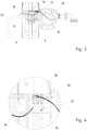
- the enlarged view of the figure 3 shows a heating means 16, which emerges from the hose 13, adjacent to the drum body disc 4 on the left in the plane of the drawing.
- This heating means 16 is arranged inside the casing of the hose 13. It runs in a spiral there.
- the heating medium 16 is an electrical conductor that heats up when a current flows through it.
- the heating means 16 is electrically conductively connected to a slip ring arrangement 17 which is located adjacent to the transmission 8 .
- the slip ring arrangement 17 is very compact and is located almost inside the drum body disk 3 on the right in the plane of the figure.
- the slip ring arrangement 17 has a fixed part 18 ( figure 6 ), to which an electrical supply line 19 is connected.
- the supply line 19 is indicated purely schematically, as is the heating means 16.
- the heating means 16 leads from the rotating part 15 of the slip ring arrangement 17 through the two drum disk bodies 3, 4 to the hose 13.
- the course of the heating means 16 between the hose 13 and the slip ring arrangement 17 in no way interferes with the winding up of the hose 13 since the heating means 16 is located very close to the central area of the hose reel arrangement 1 . Since the spokes of the connection 7 have a sufficient distance from one another, the heating means 16 or its connection to the slip ring arrangement 17 can be passed between the spokes. No modification to the inner rim 6 is required. The heating means 16 is guided past the inner ring 6 radially on the outside, as is also shown in FIG figure 6 can be seen.
- figure 6 shows, in a purely schematic representation, the electrical supply line 19 to the stationary part of the slip ring arrangement 17 and the electrical heating means 16, which leads away from the rotating part of the slip ring arrangement 17.
- slip rings are provided, which are in contact with a corresponding number of sliding contacts.
- the entire slip ring arrangement 17 is arranged to be protected from the weather (not shown).
- the three slip rings of the slip ring arrangement 17 are a flow, a return and a protective conductor of the heating means 16.
- the illustration of the other electrical connection means was omitted for reasons of clarity.
- the functional principle is based on switching on the electric heating means 16 as required when a temperature is detected on the hose 13, in the hose 13 or in the environment via measuring means, which suggests that the water in the hose 13 has frozen or that freezing imminent. Accordingly, temperature measuring devices for measuring the outside temperature and inside temperature can additionally be provided on the hose 13 , on the environment or also on the drum axis 2 .
Landscapes
- Engineering & Computer Science (AREA)
- General Engineering & Computer Science (AREA)
- Mechanical Engineering (AREA)
- Pipe Accessories (AREA)
- Storing, Repeated Paying-Out, And Re-Storing Of Elongated Articles (AREA)
Description
- Die Erfindung betrifft eine Schlauchtrommelanordnung mit den Merkmalen im Patentanspruch 1.
- Schlauchtrommeln dienen dem geordneten Auf- und Abwickeln von Schläuchen. Schlauchtrommeln sind bei Minusgraden nur bedingt einsetzbar, weil die Gefahr besteht, dass Wasser im Schlauch gefriert, wenn der Fluidstrom unterbrochen wird. Eine Erwärmung von außen ist bei einem aufgewickelten Schlauch über die gesamte Länge kaum möglich und sehr energieaufwendig. Praktisch müsste die gesamte Schlauchtrommel in einem aufgewärmten Raum aufbewahrt werden. In der
EP 2 499 904 B1 wird vorgeschlagen, den Schlauch nicht von außen, sondern von innen zu erwärmen, indem in den Schlauch ein elektrisches Heizmittel eingebracht wird. Über eine Schleifringanordnung wird das elektrische Heizmittel mit Energie versorgt. Wenn die Ausflussmenge konstant gehalten werden soll, muss der Schlauchdurchmesser vergrößert werden. - Die
EP 1 329 660 A2 offenbart einen flexiblen, mehrschichtigen, beheizbaren Schlauch für die Durchleitung einer Flüssigkeit. Der Schlauch ist flexibel und der Heizleiter wendeiförmig in den Mantel des Schlauches eingebettet. Der elektrische Leiter soll durch die Ummantelung geschützt werden, um eine elektrische Isolierung zu gewährleisten, so dass es zu keiner Beeinträchtigung durch Korrosion oder Kurzschluss infolge eindringender Feuchtigkeit kommen kann. Ein solcher Schlauch kommt insbesondere als flexibler, beheizbarer Druckschlauch für Kraftfahrzeuge zum Einsatz. Bei dieser Art der Verwendung sind die Enden des Schlauches ortsfest, so dass der elektrische Heizleiter ebenfalls über ortsfeste Anschlüsse an jedem Ende mit einer zum Betreiben des Heizleiters erforderlichen Spannungsquelle verbunden werden kann. Bei einer Schlauchtrommel ist mindestens ein Ende des Schlauches verlagerbar, sei es, weil es sich mit der Schlauchtrommel dreht oder weil bei ortsfester Schlauchtrommel auch das andere Ende des Schlauches verlagert wird. Eine ortsfeste Einspeisung von Strom ist nicht möglich. - Die
US 3 314 562 offenbart eine Vakuumvorrichtung, um Gegenstände anzuheben, bei welcher ein elektrischer Leiter innerhalb eines Schlauches verlaufen soll, um eine weitere Kabeltrommel einzusparen und um das Kabel in dem Schlauch zu schützen. Im Bereich der Schlauchtrommel ist das Kabel über einen Schleifringübertrager elektrisch leitend verbunden. - Der Erfindung liegt die Aufgabe zugrunde, eine Schlauchtrommelanordnung aufzuzeigen, die auch bei kalter Witterung eingesetzt werden kann und bei welcher große Ausflussmengen bei geringen Schlauchdurchmessern realisiert werden können.
- Diese Aufgabe ist bei einer Schlauchtrommelanordnung mit den Merkmalen des Patentanspruchs 1 gelöst.
- Die Unteransprüche betreffen vorteilhafte Weiterbildungen der Erfindung.
- Die erfindungsgemäße Schlauchtrommelanordnung besitzt einen Trommelkörper mit einer Trommelachse und an der Trommelachse angeordnete Trommelkörperscheiben. Die Trommelkörperscheiben begrenzen die Wickelbreite. Es kann sich um eine Schlauchtrommelanordnung handeln, die spiralförmig oder auch zylindrisch wickelt. Kombinationen sind möglich. Eine spiralische Wicklung kann z.B. in zwei Reihen nebeneinander ausgeführt werden. Ebenso kann eine zylindrische Wicklung in mehreren Lagen übereinander ausgeführt werden.
- Der Trommelkörper ist über eine Trommelachse drehbar gelagert. Die Trommelachse trägt den Schlauch und die Trommelkörperscheiben. Je nach Dimensionierung der Schlauchtrommelanordnung sind ein oder zwei Lager für die Trommelachse erforderlich.
- Die Trommelachse ist zumindest teilweise als Fluidleitung ausgebildet, an welche der aufzuwickelnde Schlauch angeschlossen ist. Bei zylindrisch wickelnden Schlauchtrommelanordnungen ist die Trommelachse vergleichsweise lang. In diesem Fall ist es nicht erforderlich, die gesamte Trommelachse als Fluidleitung auszubilden. Bei spiralförmig wickelnden Schlauchtrommelanordnungen ist die Trommelachse kurz. Ein einziges Lager reicht aus. An die drehbare Trommelachse ist dann einerseits eine Drehdurchführung mit einer nicht drehbaren Zuleitung angeschlossen und andererseits der Schlauch. Er wird nach radial außen über eine Wickeltrommel geführt, die sich zwischen den Trommelkörperscheiben befindet.
- Neben der Drehdurchführung ist auf der Trommelachse eine Schleifringanordnung angeordnet. Über die Schleifringanordnung kann elektrische Energie in ein Heizmittel eingespeist werden. Hierzu ist das Heizmittel elektrisch an die Schleifringanordnung angeschlossen. Das Heizmittel ist in den Mantel des Schlauches eingebettet. Das Einbetten hat den Vorteil, dass der innere Querschnitt des Schlauches komplett frei bleibt. Es entstehen keine Verwirbelungen innerhalb des Schlauches und dadurch auch keine durch den Heizleiter verursachten Strömungsverluste. Das bedeutet wiederum, dass sich die Ausflussmenge nicht reduziert. Im Vergleich zu Schläuchen mit einer innenliegenden Heizwendel können bei gleicher Ausflussmenge Schläuche mit geringeren Innendurchmessern zum Einsatz kommen. Kleinere Schlauchdurchmesser bedeuten gleichzeitig kleinere Schlauchtrommelanordnungen. Dadurch benötigen die Schlauchtrommel-anordnungen weniger Bauraum. Selbst Nachrüstungen von bestehenden Schlauchtrommeln sind möglich.
- Das Heizmittel in der Schlauchwand ist vorzugsweise ein Heizband. Dieses Heizband ist in der Lage, das im Schlauch befindliche Wasser über einer Temperatur von 0°C zu halten.
- Die Schleifringanordnung befindet sich außerhalb des Wickelbereiches für den Schlauch. Der Schlauch mit dem in dem Mantel eingebetteten Heizmittel ist daher auf der der Schleifringanordnung abgewandten Seite der Trommelkörperscheiben angeordnet und dort mit der Trommelachse verbunden. Die Trommelkörperscheibe steht der Verbindung des Heizmittels mit der Schleifringanordnung im Weg. Erfindungsgemäß ist vorgesehen, dass das Heizmittel auf der einen Seite einer Trommelkörperscheibe nach radial außen aus dem Schlauch herausgeführt ist. Das Heizmittel wird nun außenseitig entlang der Trommelachse weitergeführt und durchsetzt eine Öffnung in der Trommelkörperscheibe. Das Heizmittel ist in diesem Bereich gegen seine Umgebung isoliert.
- Das Heizmittel muss in seinem Verlauf von der Schleifringanordnung bis zum Eintritt in den Schlauch keine Wärme abgeben. Das Heizmittel kann in diesem Übergangsbereich auch als Draht mit entsprechendem Querschnitt ausgeführt werden, so dass keine thermischen Belastungen im Bereich der Trommelkörperscheiben entsteht.
- Das Heizmittel kann als flexibles Band sehr platzsparend und ohne großen Aufwand von dem Schlauch zu dem mitdrehenden Teil der Schleifringanordnung geführt werden. Im Unterschied zu einer innenliegenden Heizwendel ist es nicht erforderlich, das Heizmittel durch ein Zugmittel gegen die Strömungskraft im Schlauch zu sichern. Es erfolgt keinerlei Querschnittsreduzierung des inneren Schlauchdurchmessers.
- Je nachdem, ob es sich um eine zylindrische oder eine spiralig wickelnde Schlauchtrommel handelt, kann das Heizmittel durch nur eine Trommelkörperscheibe geführt werden (zylindrisch wickelnde Schlauchtrommel) oder auch durch beide Trommelkörperscheiben (spiralig wickelnde Schlauchtrommeln).
- Die erfindungsgemäße Schlauchtrommelanordnung besitzt vorzugsweise einen Innenkranz und einen Außenkranz an ihren jeweiligen Trommelkörperscheiben. Zwischen dem Innenkranz und dem Außenkranz gibt es Verbinder, die den Außenkranz mit dem Innenkranz verbinden. Der Innenkranz dient gewissermaßen als Flansch für die Verbinder. Bei den Verbindern kann es sich vorzugsweise um Speichen handeln. Auch eine scheibenförmige Verbindung zwischen Innen- und Außenkranz ist möglich. In diesem Fall muss ein Durchbruch für das Heizmittel in der Trommelkörperscheibe erzeugt werden. Bei der Verwendung von Speichen ist das nicht erforderlich. Vorzugsweise wird das Heizmittel radial außenseitig an dem Innenkranz vorbeigeführt. In diesem Fall kann das Heizmittel zwischen den Speichen hindurchgeführt werden. Die Struktur der Verbinder bzw. die Auslegung des Innenkranzes, der als Flansch für die Verbinder dient, muss nicht modifiziert werden. Daher sind Schlauchtrommelanordnungen mit einem geeigneten Schlauch sowie mit entsprechendem Heizmittel nachrüstbar.
- Das Heizmittel selbst verläuft innerhalb des Mantels vorzugsweise wendelförmig. Der Schlauch sollte aufgrund des eingebetteten Heizmittels nicht geknickt werden. Die wendelförmige Anordnung im Mantel hilft, Beschädigungen des Heizmittels zu vermeiden. Die Wendelform schafft Bewegungsreserven. Sollte der Schlauch gedehnt oder gestaucht werden oder sich unter thermischen Einflüssen längen oder zusammenziehen, kommt es durch wendeiförmig angeordnete Heizmittel nicht zu Beschädigungen der Heizeinrichtung. Je kleiner die Steigung des wendeiförmigen Heizmittels ist, desto größer ist der Energieeintrag je Längeneinheit des Schlauches. Das Heizmittel ist daher vorzugsweise länger als der Schlauchabschnitt, der aufgeheizt werden soll.
- Die erfindungsgemäße Schlauchtrommelanordnung umfasst vorzugsweise wenigstens eine Temperaturmesseinrichtung. Sie dient dazu, die Temperatur eines den Schlauch durchströmenden Fluids zu messen. Ein Kaltleiter besitzt einen sehr großen Messbereich, ist einfach montierbar und sowohl mit, als auch ohne Ummantelung direkt an oder in dem Schlauch verbaubar. Über eine Datenleitung können Messsignale der Temperaturmesseinrichtung einer Auswerteeinheit zugeleitet werden. Diese Auswerteeinheit kann wiederum mit einer Steuereinheit verbunden sein, die dafür vorgesehen ist, bei Unterschreiten einer unteren Temperatur im Schlauch und/oder der Umgebungstemperatur die Einspeisung elektrischer Energie in die Heizmittel freizugeben und bei Überschreiten einer oberen Temperatur die Einspeisung zu beenden. Hierdurch kann das Gefrieren von Wasser im Schlauch wirksam verhindert werden.
- Die Schlauchtrommelanordnung wird so betrieben, dass ein elektrisches Heizmittel angeschaltet wird, wenn die Temperaturmesseinrichtung im Schlauch das Unterschreiten einer unteren Temperatur misst. Durch diese Frostwächterfunktion wird die permanente Betriebssicherheit der Schlauchtrommelanordnung gewährleistet. Das Heizmittel wird durch die Steuereinheit abgeschaltet, sobald eine obere Temperatur im Schlauch überschritten wird. Das Heizmittel wird so angesteuert, dass es in Abhängigkeit von den Temperaturen innerhalb und außerhalb des Schlauches ein- und ausgeschaltet wird. Dadurch kann einem frühzeitigen Gefrieren des zu transportierenden Fluides entgegengewirkt werden.
- Die Erfindung wird nachfolgend anhand der in den Figuren gezeigten schematischen Ausführungsbeispielen näher beschrieben. Es zeigen:
- Figur 1
- eine spiralig wickelnde Schlauchtrommelanordnung in einer Frontansicht;
- Figur 2
- die Schlauchtrommelanordnung der
Figur 1 in einer Ansicht senkrecht zur Wickelachse; - Figur 3
- den Ausschnitt III der
Figur 2 ; - Figur 4
- Ausschnitt IV der
Figur 3 ; - Figur 5
- die Schlauchtrommelanordnung der
Figur 1 in einer perspektivischen Darstellung und - Figur 6
- Ausschnitt VI der
Figur 5 . -
Figur 1 zeigt eine Schlauchtrommelanordnung 1 in Blickrichtung ihrer Drehachse. Es handelt sich um eine Schlauchtrommelanordnung 1, die spiralig wickelt und daher einen relativ großen Durchmesser besitzt. Diese Schlauchtrommelanordnung 1 ist für den Einsatz im Außenbereich vorgesehen. Die Schlauchtrommelanordnung 1 besitzt eine Trommelachse 2 (Figur 2 ) und an der Trommelachse 2 angeordnete Trommelkörperscheiben 3, 4. Die Trommelkörperscheiben 3, 4 besitzen einen Außenkranz 5 und einen Innenkranz 6. Zwischen dem Außenkranz 5 und dem Innenkranz 6 befinden sich Verbinder 7 in Form von Speichen, die von radial innen nach radial außen strahlenförmig und gerade zwischen dem Innenkranz 5 und dem Außenkranz 6 verlaufen. Der Innenkranz 6 kann auch als Trommelflansch bezeichnet werden. - An der Drehachse der Schlauchtrommelanordnung 1 befindet sich ein Getriebe 8 mit einer daran angeordneten Antriebseinheit 9. In diesem Ausführungsbeispiel handelt es sich um einen Elektromotor. In nicht näher dargestellter Weise wird die Trommelachse 6 innerhalb des Getriebes 8 gelagert.
-
Figur 2 zeigt, dass in Verlängerung der Drehachse eine Drehdurchführung 10 an der Trommelachse 2 angeordnet ist. Die Drehdurchführung 10 ist über einen Krümmer 11 mit einem nicht näher dargestellten Einspeisepunkt verbunden. Der Einspeisepunkt 12, der Krümmer 11 und das Getriebe 8 mit der Antriebseinheit 9 sind ortsfest. Demgegenüber dreht sich die Drehachse 2 zusammen mit den Trommelkörperscheiben 3, 4. Ebenso dreht sich zusammen mit den Trommelkörperscheiben 3, 4 ein Schlauch 13 mit. InFigur 2 ist zu erkennen, dass der Schlauch 13 auf der dem Getriebe 8 abgewandten Seite aus der Schlauchtrommelanordnung 1 herausgeführt ist. Im Bogen wird er wieder zwischen die beiden Trommelkörperscheiben 3 und 4 geführt. In nicht näher dargestellter Weise wird der Schlauch 13 dort auf eine Wickeltrommel 14 aufgewickelt, wie sie inFigur 1 zu erkennen ist. - Die vergrößerte Darstellung der
Figur 3 zeigt ein Heizmittel 16, das aus dem Schlauch 13, benachbart der in der Bildebene linken Trommelkörperscheibe 4, aus dem Schlauch 13 austritt. Dieses Heizmittel 16 ist innerhalb des Mantels des Schlauches 13 angeordnet. Es verläuft dort wendelförmig. Das Heizmittel 16 ist ein elektrischer Leiter, der sich erwärmt, wenn ein Strom durch ihn fließt. Das Heizmittel 16 ist elektrisch leitend an eine Schleifringanordnung 17 angeschlossen, die sich benachbart dem Getriebe 8 befindet. Die Schleifringanordnung 17 ist sehr kompakt und befindet sich nahezu innerhalb der in der Bildebene rechten Trommelkörperscheibe 3. Die Schleifringanordnung 17 besitzt einen feststehenden Teil 18 (Figur 6 ), an den eine elektrische Zuleitung 19 angeschlossen ist. Die Zuleitung 19 ist rein schematisch angedeutet, ebenso wie das Heizmittel 16. Das Heizmittel 16 führt von dem sich mitdrehenden Teil 15 der Schleifringanordnung 17 durch die beiden Trommelscheibenkörper 3, 4 hindurch zu dem Schlauch 13. - Der Verlauf des Heizmittels 16 zwischen dem Schlauch 13 und der Schleifringanordnung 17 stört das Aufwickeln des Schlauches 13 in keiner Weise, da sich das Heizmittel 16 sehr nah im Zentralbereich der Schlauchtrommelanordnung 1 befindet. Da die Speichen der Verbindung 7 einen hinreichenden Abstand zueinander haben, kann das Heizmittel 16 bzw. dessen Verbindung zur Schleifringanordnung 17 zwischen den Speichen hindurchgeführt werden. Es ist keine Modifikation an dem Innenkranz 6 erforderlich. Das Heizmittel 16 wird radial außenseitig an dem Innenkranz 6 vorbeigeführt, wie es auch in
Figur 6 zu erkennen ist. -
Figur 6 zeigt in rein schematischer Darstellung die elektrische Zuleitung 19 zu dem feststehenden Teil der Schleifringanordnung 17 und das elektrische Heizmittel 16, das von dem sich drehenden Teil der Schleifringanordnung 17 wegführt. - Anhand der
Figur 4 ist erkennen, dass mehrere Schleifringe vorgesehen sind, die mit einer entsprechenden Anzahl von Schleifkontakten in Kontakt stehen. In diesem Ausführungsbeispiel handelt es sich um drei Schleifkontakte. Die gesamte Schleifringanordnung 17 ist witterungsgeschützt angeordnet (nicht dargestellt). Die drei Schleifringe der Schleifringanordnung 17 sind ein Vorlauf, ein Rücklauf und ein Schutzleiter des Heizmittels 16. Auf die Darstellung der weiteren elektrischen Anschlussmittel wurde aus Gründen der Übersichtlichkeit verzichtet. Das Funktionsprinzip basiert darauf, das elektrische Heizmittel 16 bedarfsgerecht anzuschalten, wenn über Messmittel eine Temperatur am Schlauch 13, im Schlauch 13 oder in der Umgebung festgestellt wird, die auf ein Gefrieren des Wassers im Schlauch 13 schließen lässt oder darauf schließen lässt, dass ein Gefrieren bevorsteht. Temperaturmesseinrichtungen zur Messung der Außentemperatur und Innentemperatur können dementsprechend zusätzlich an dem Schlauch 13, an der Umgebung oder auch an der Trommelachse 2 vorgesehen sein. -
- 1 -
- Schlauchtrommelanordnung
- 2 -
- Trommelachse
- 3 -
- Trommelkörperscheibe
- 4 -
- Trommelkörperscheibe
- 5 -
- Außenkranz
- 6 -
- Innenkranz
- 7 -
- Verbindung in Form einer Speiche
- 8 -
- Getriebe
- 9 -
- Antriebseinheit
- 10 -
- Drehdurchführung
- 11 -
- Krümmer
- 12 -
- Einspeisepunkt
- 13 -
- Schlauch
- 14 -
- Wickelmantel
- 15 -
- Beweglicher Teil von 17
- 16 -
- Heizmittel
- 17 -
- Schleifringanordnung
- 18 -
- Feststehender Teil von 17
- 19 -
- Elektrische Zuleitung
Claims (8)
- Schlauchtrommelanordnung mit folgenden Merkmalen:- Ein Trommelkörper besitzt eine Trommelachse (2) und an der Trommelachse (2) angeordnete Trommelkörperscheiben (3, 4);- der Trommelkörper ist über seine Trommelachse (2) drehbar gelagert und ist dafür vorgesehen, einen Schlauch (13) der Schlauchtrommelanordnung (1) wickelnd aufzunehmen;- die Trommelachse (2) ist als Fluidleitung ausgebildet, an welche der aufzuwickelnde Schlauch (13) angeschlossen ist;- die drehbare Trommelachse (2) ist über eine Drehdurchführung (10) mit einer nicht drehbaren Zuleitung der Schlauchtrommelanordnung (1) verbunden;- mittels einer Schleifringanordnung (17) der Schlauchtrommelanordnung (1) ist elektrische Energie in ein Heizmittel (16) einspeisbar;- das Heizmittel (16) ist auf einer Seite einer Trommelkörperscheibe (3, 4) aus dem Schlauch (13) herausgeführt,dadurch gekennzeichnet, dass- das Heizmittel (16) in den Mantel des Schlauches (13) eingebettet ist, wobei das Heizmittel (16) in seinem weiteren Verlauf von dem Schlauch (13) kommend die Trommelkörperscheibe (3, 4) durchsetzt und außenseitig der Trommelachse (2) zu einem sich mit der Trommelachse (2) mitdrehenden Teil (15) der Schleifringanordnung (17) verläuft.
- Schlauchtrommelanordnung nach Anspruch 1, dadurch gekennzeichnet, dass die Trommelkörperscheiben (3, 4) einen Innenkranz (6) und einen Außenkranz (5) haben sowie Verbinder (7), die den Außenkranz (5) mit dem Innenkranz (6) verbinden, wobei das Heizmittel (16) radial außenseitig an dem Innenkranz (6) vorbeigeführt ist.
- Schlauchtrommelanordnung nach Anspruch 2, dadurch gekennzeichnet, dass das Heizmittel (16) zwischen den als Speichen ausgeführten Verbindern (7) hindurchgeführt ist.
- Schlauchtrommelanordnung nach einem der Ansprüche 1 bis 3, dadurch gekennzeichnet, dass das Heizmittel (16) wendeiförmig innerhalb des Mantels des Schlauches (13) verläuft.
- Schlauchtrommelanordnung nach einem der Ansprüche 1 bis 4, dadurch gekennzeichnet, dass eine Temperaturmesseinrichtung vorgesehen ist zur Messung der Temperatur eines den Schlauch (13) durchströmenden Fluids.
- Schlauchtrommelanordnung nach Anspruch 5, dadurch gekennzeichnet, dass die Temperaturmesseinrichtung eine Datenleitung umfasst, über welche ein Messsignal einer Auswerteeinheit zugeleitet wird.
- Schlauchtrommelanordnung nach einem der Ansprüche 1 bis 6, dadurch gekennzeichnet, dass außerhalb des Schlauches (13) eine weitere Temperaturmesseinrichtung angeordnet ist, die mit einer Auswerteeinheit verbunden ist.
- Schlauchtrommelanordnung nach Anspruch 6 oder 7, dadurch gekennzeichnet, dass die Auswerteeinheit mit einer Steuereinheit verbunden ist, welche dafür vorgesehen ist, bei Unterschreiten einer unteren Temperatur im Schlauch (13) und/oder der Umgebungstemperatur die Einspeisung elektrischer Energie in die Heizmittel (16) freizugeben und bei Überschreiten einer oberen Temperatur die Einspeisung zu beenden.
Priority Applications (1)
| Application Number | Priority Date | Filing Date | Title |
|---|---|---|---|
| PL19174208T PL3594545T3 (pl) | 2018-07-13 | 2019-05-13 | Układ bębnowy na wąż |
Applications Claiming Priority (1)
| Application Number | Priority Date | Filing Date | Title |
|---|---|---|---|
| DE102018117048.3A DE102018117048B4 (de) | 2018-07-13 | 2018-07-13 | Schlauchtrommelanordnung |
Publications (2)
| Publication Number | Publication Date |
|---|---|
| EP3594545A1 EP3594545A1 (de) | 2020-01-15 |
| EP3594545B1 true EP3594545B1 (de) | 2022-02-09 |
Family
ID=66542041
Family Applications (1)
| Application Number | Title | Priority Date | Filing Date |
|---|---|---|---|
| EP19174208.9A Not-in-force EP3594545B1 (de) | 2018-07-13 | 2019-05-13 | Schlauchtrommelanordnung |
Country Status (3)
| Country | Link |
|---|---|
| EP (1) | EP3594545B1 (de) |
| DE (1) | DE102018117048B4 (de) |
| PL (1) | PL3594545T3 (de) |
Family Cites Families (7)
| Publication number | Priority date | Publication date | Assignee | Title |
|---|---|---|---|---|
| US3314562A (en) * | 1964-09-14 | 1967-04-18 | Cascade Corp | Hose and electrical cable system |
| US3378673A (en) * | 1965-10-18 | 1968-04-16 | Thomas O. Hopper | Electrically heated hose assembly |
| DE10201920B4 (de) | 2002-01-19 | 2018-04-12 | Contitech Schlauch Gmbh | Verfahren zum Verbinden eines Heizleiters eines flexiblen mehrschichtigen Schlauches mit einer elektrischen Anschlussvorrichtung |
| DE10207794B4 (de) * | 2002-02-25 | 2004-02-05 | Klaus Winkler | Beheizbare Leitung |
| DE202010013463U1 (de) * | 2010-09-23 | 2011-02-03 | J. Wagner Gmbh | Vorrichtung zur Aufnahme und Aufbewahrung eines Schlauches mit Heizsystem |
| DE102011014520A1 (de) | 2011-03-18 | 2012-09-20 | Stemmann-Technik Gmbh | Schlauchtrommelanordnung mit Heizmittel im Schlauch |
| MX2016010548A (es) * | 2014-02-14 | 2016-11-29 | Parker Hannifin Corp | Manguera calentada y metodo. |
-
2018
- 2018-07-13 DE DE102018117048.3A patent/DE102018117048B4/de not_active Expired - Fee Related
-
2019
- 2019-05-13 EP EP19174208.9A patent/EP3594545B1/de not_active Not-in-force
- 2019-05-13 PL PL19174208T patent/PL3594545T3/pl unknown
Also Published As
| Publication number | Publication date |
|---|---|
| DE102018117048A1 (de) | 2020-01-16 |
| EP3594545A1 (de) | 2020-01-15 |
| DE102018117048B4 (de) | 2021-02-25 |
| PL3594545T3 (pl) | 2022-07-11 |
Similar Documents
| Publication | Publication Date | Title |
|---|---|---|
| DE60305516T2 (de) | Beheizte leitung | |
| EP3882929B1 (de) | Kühlbare einzelleitung und ladekabel | |
| DE3702323C2 (de) | ||
| WO2020053104A1 (de) | Kühlbare einzelleitung und ladekabel | |
| WO2015150277A1 (de) | Kühlvorrichtung | |
| EP1329660B1 (de) | Flexibler, mehrschichtiger, beheizbarer Schlauch | |
| DE3414284C2 (de) | ||
| EP4308842B1 (de) | Vorrichtung zur temperierung von fluiden | |
| DE102018117048B4 (de) | Schlauchtrommelanordnung | |
| EP2499904B1 (de) | Schlauchtrommelanordnung mit heizmittel im schlauch | |
| DE4042056C2 (de) | Vorrichtung zum Medientransport mittels thermisch isolierter Rohre und Verfahren zu deren Herstellung | |
| AT413589B (de) | Flexibler kryogener schlauch | |
| DE3018781C2 (de) | Thermisch isoliertes Leitungsrohr | |
| WO2012172110A1 (de) | Vorrichtung zum ab- und aufwickeln einer oder mehreren leitungen | |
| EP4402084B1 (de) | Trommelanordnung | |
| EP2354613A1 (de) | Verfahren zur Herstellung eines Rohrverbunds | |
| DE10012950B4 (de) | Gekühlte Kabel, insbesondere luftgekühlte Kabel | |
| DE102011090207A1 (de) | Bevorratungsvorrichtung | |
| DE19922152C2 (de) | Kabelanordnung für ein Hubschrauberrotorblatt | |
| EP2329896A1 (de) | Vorrichtung zum kontinuierlichen Wellen eines metallischen Rohres | |
| DE102004015801B4 (de) | Anlage zur Herstellung von Kabeln mit speziell ausgebildetem Teleskoprohr | |
| EP2416046B1 (de) | Leitungsrohr zum Transport von temperierten, fließfähigen Medien | |
| EP0641728A1 (de) | Tankanlage | |
| DE3312025C2 (de) | ||
| WO2019105625A1 (de) | Mit salzschmelze betriebenes solarthermisches kraftwerk |
Legal Events
| Date | Code | Title | Description |
|---|---|---|---|
| PUAI | Public reference made under article 153(3) epc to a published international application that has entered the european phase |
Free format text: ORIGINAL CODE: 0009012 |
|
| STAA | Information on the status of an ep patent application or granted ep patent |
Free format text: STATUS: THE APPLICATION HAS BEEN PUBLISHED |
|
| AK | Designated contracting states |
Kind code of ref document: A1 Designated state(s): AL AT BE BG CH CY CZ DE DK EE ES FI FR GB GR HR HU IE IS IT LI LT LU LV MC MK MT NL NO PL PT RO RS SE SI SK SM TR |
|
| AX | Request for extension of the european patent |
Extension state: BA ME |
|
| STAA | Information on the status of an ep patent application or granted ep patent |
Free format text: STATUS: REQUEST FOR EXAMINATION WAS MADE |
|
| 17P | Request for examination filed |
Effective date: 20200630 |
|
| GRAJ | Information related to disapproval of communication of intention to grant by the applicant or resumption of examination proceedings by the epo deleted |
Free format text: ORIGINAL CODE: EPIDOSDIGR1 |
|
| STAA | Information on the status of an ep patent application or granted ep patent |
Free format text: STATUS: GRANT OF PATENT IS INTENDED |
|
| GRAP | Despatch of communication of intention to grant a patent |
Free format text: ORIGINAL CODE: EPIDOSNIGR1 |
|
| RIC1 | Information provided on ipc code assigned before grant |
Ipc: B65H 75/14 20060101ALI20210825BHEP Ipc: B65H 75/44 20060101ALI20210825BHEP Ipc: F16L 53/38 20180101ALI20210825BHEP Ipc: F16L 53/35 20180101ALI20210825BHEP Ipc: F16L 11/12 20060101ALI20210825BHEP Ipc: B65H 75/00 20060101ALI20210825BHEP Ipc: F16L 3/01 20060101AFI20210825BHEP |
|
| INTG | Intention to grant announced |
Effective date: 20210910 |
|
| GRAS | Grant fee paid |
Free format text: ORIGINAL CODE: EPIDOSNIGR3 |
|
| GRAA | (expected) grant |
Free format text: ORIGINAL CODE: 0009210 |
|
| STAA | Information on the status of an ep patent application or granted ep patent |
Free format text: STATUS: THE PATENT HAS BEEN GRANTED |
|
| AK | Designated contracting states |
Kind code of ref document: B1 Designated state(s): AL AT BE BG CH CY CZ DE DK EE ES FI FR GB GR HR HU IE IS IT LI LT LU LV MC MK MT NL NO PL PT RO RS SE SI SK SM TR |
|
| REG | Reference to a national code |
Ref country code: GB Ref legal event code: FG4D Free format text: NOT ENGLISH |
|
| REG | Reference to a national code |
Ref country code: CH Ref legal event code: EP Ref country code: AT Ref legal event code: REF Ref document number: 1467708 Country of ref document: AT Kind code of ref document: T Effective date: 20220215 |
|
| REG | Reference to a national code |
Ref country code: DE Ref legal event code: R096 Ref document number: 502019003383 Country of ref document: DE |
|
| REG | Reference to a national code |
Ref country code: IE Ref legal event code: FG4D Free format text: LANGUAGE OF EP DOCUMENT: GERMAN |
|
| REG | Reference to a national code |
Ref country code: LT Ref legal event code: MG9D |
|
| REG | Reference to a national code |
Ref country code: NL Ref legal event code: MP Effective date: 20220209 |
|
| PG25 | Lapsed in a contracting state [announced via postgrant information from national office to epo] |
Ref country code: SE Free format text: LAPSE BECAUSE OF FAILURE TO SUBMIT A TRANSLATION OF THE DESCRIPTION OR TO PAY THE FEE WITHIN THE PRESCRIBED TIME-LIMIT Effective date: 20220209 Ref country code: RS Free format text: LAPSE BECAUSE OF FAILURE TO SUBMIT A TRANSLATION OF THE DESCRIPTION OR TO PAY THE FEE WITHIN THE PRESCRIBED TIME-LIMIT Effective date: 20220209 Ref country code: PT Free format text: LAPSE BECAUSE OF FAILURE TO SUBMIT A TRANSLATION OF THE DESCRIPTION OR TO PAY THE FEE WITHIN THE PRESCRIBED TIME-LIMIT Effective date: 20220609 Ref country code: NO Free format text: LAPSE BECAUSE OF FAILURE TO SUBMIT A TRANSLATION OF THE DESCRIPTION OR TO PAY THE FEE WITHIN THE PRESCRIBED TIME-LIMIT Effective date: 20220509 Ref country code: NL Free format text: LAPSE BECAUSE OF FAILURE TO SUBMIT A TRANSLATION OF THE DESCRIPTION OR TO PAY THE FEE WITHIN THE PRESCRIBED TIME-LIMIT Effective date: 20220209 Ref country code: LT Free format text: LAPSE BECAUSE OF FAILURE TO SUBMIT A TRANSLATION OF THE DESCRIPTION OR TO PAY THE FEE WITHIN THE PRESCRIBED TIME-LIMIT Effective date: 20220209 Ref country code: HR Free format text: LAPSE BECAUSE OF FAILURE TO SUBMIT A TRANSLATION OF THE DESCRIPTION OR TO PAY THE FEE WITHIN THE PRESCRIBED TIME-LIMIT Effective date: 20220209 Ref country code: ES Free format text: LAPSE BECAUSE OF FAILURE TO SUBMIT A TRANSLATION OF THE DESCRIPTION OR TO PAY THE FEE WITHIN THE PRESCRIBED TIME-LIMIT Effective date: 20220209 Ref country code: BG Free format text: LAPSE BECAUSE OF FAILURE TO SUBMIT A TRANSLATION OF THE DESCRIPTION OR TO PAY THE FEE WITHIN THE PRESCRIBED TIME-LIMIT Effective date: 20220509 |
|
| PG25 | Lapsed in a contracting state [announced via postgrant information from national office to epo] |
Ref country code: LV Free format text: LAPSE BECAUSE OF FAILURE TO SUBMIT A TRANSLATION OF THE DESCRIPTION OR TO PAY THE FEE WITHIN THE PRESCRIBED TIME-LIMIT Effective date: 20220209 Ref country code: GR Free format text: LAPSE BECAUSE OF FAILURE TO SUBMIT A TRANSLATION OF THE DESCRIPTION OR TO PAY THE FEE WITHIN THE PRESCRIBED TIME-LIMIT Effective date: 20220510 Ref country code: FI Free format text: LAPSE BECAUSE OF FAILURE TO SUBMIT A TRANSLATION OF THE DESCRIPTION OR TO PAY THE FEE WITHIN THE PRESCRIBED TIME-LIMIT Effective date: 20220209 |
|
| PG25 | Lapsed in a contracting state [announced via postgrant information from national office to epo] |
Ref country code: IS Free format text: LAPSE BECAUSE OF FAILURE TO SUBMIT A TRANSLATION OF THE DESCRIPTION OR TO PAY THE FEE WITHIN THE PRESCRIBED TIME-LIMIT Effective date: 20220609 |
|
| PG25 | Lapsed in a contracting state [announced via postgrant information from national office to epo] |
Ref country code: SM Free format text: LAPSE BECAUSE OF FAILURE TO SUBMIT A TRANSLATION OF THE DESCRIPTION OR TO PAY THE FEE WITHIN THE PRESCRIBED TIME-LIMIT Effective date: 20220209 Ref country code: SK Free format text: LAPSE BECAUSE OF FAILURE TO SUBMIT A TRANSLATION OF THE DESCRIPTION OR TO PAY THE FEE WITHIN THE PRESCRIBED TIME-LIMIT Effective date: 20220209 Ref country code: RO Free format text: LAPSE BECAUSE OF FAILURE TO SUBMIT A TRANSLATION OF THE DESCRIPTION OR TO PAY THE FEE WITHIN THE PRESCRIBED TIME-LIMIT Effective date: 20220209 Ref country code: EE Free format text: LAPSE BECAUSE OF FAILURE TO SUBMIT A TRANSLATION OF THE DESCRIPTION OR TO PAY THE FEE WITHIN THE PRESCRIBED TIME-LIMIT Effective date: 20220209 Ref country code: DK Free format text: LAPSE BECAUSE OF FAILURE TO SUBMIT A TRANSLATION OF THE DESCRIPTION OR TO PAY THE FEE WITHIN THE PRESCRIBED TIME-LIMIT Effective date: 20220209 Ref country code: CZ Free format text: LAPSE BECAUSE OF FAILURE TO SUBMIT A TRANSLATION OF THE DESCRIPTION OR TO PAY THE FEE WITHIN THE PRESCRIBED TIME-LIMIT Effective date: 20220209 |
|
| REG | Reference to a national code |
Ref country code: DE Ref legal event code: R097 Ref document number: 502019003383 Country of ref document: DE |
|
| PG25 | Lapsed in a contracting state [announced via postgrant information from national office to epo] |
Ref country code: AL Free format text: LAPSE BECAUSE OF FAILURE TO SUBMIT A TRANSLATION OF THE DESCRIPTION OR TO PAY THE FEE WITHIN THE PRESCRIBED TIME-LIMIT Effective date: 20220209 |
|
| PLBE | No opposition filed within time limit |
Free format text: ORIGINAL CODE: 0009261 |
|
| STAA | Information on the status of an ep patent application or granted ep patent |
Free format text: STATUS: NO OPPOSITION FILED WITHIN TIME LIMIT |
|
| REG | Reference to a national code |
Ref country code: CH Ref legal event code: PL |
|
| 26N | No opposition filed |
Effective date: 20221110 |
|
| REG | Reference to a national code |
Ref country code: BE Ref legal event code: MM Effective date: 20220531 |
|
| PG25 | Lapsed in a contracting state [announced via postgrant information from national office to epo] |
Ref country code: MC Free format text: LAPSE BECAUSE OF FAILURE TO SUBMIT A TRANSLATION OF THE DESCRIPTION OR TO PAY THE FEE WITHIN THE PRESCRIBED TIME-LIMIT Effective date: 20220209 Ref country code: LU Free format text: LAPSE BECAUSE OF NON-PAYMENT OF DUE FEES Effective date: 20220513 Ref country code: LI Free format text: LAPSE BECAUSE OF NON-PAYMENT OF DUE FEES Effective date: 20220531 Ref country code: CH Free format text: LAPSE BECAUSE OF NON-PAYMENT OF DUE FEES Effective date: 20220531 |
|
| PG25 | Lapsed in a contracting state [announced via postgrant information from national office to epo] |
Ref country code: SI Free format text: LAPSE BECAUSE OF FAILURE TO SUBMIT A TRANSLATION OF THE DESCRIPTION OR TO PAY THE FEE WITHIN THE PRESCRIBED TIME-LIMIT Effective date: 20220209 |
|
| PG25 | Lapsed in a contracting state [announced via postgrant information from national office to epo] |
Ref country code: IE Free format text: LAPSE BECAUSE OF NON-PAYMENT OF DUE FEES Effective date: 20220513 |
|
| PG25 | Lapsed in a contracting state [announced via postgrant information from national office to epo] |
Ref country code: BE Free format text: LAPSE BECAUSE OF NON-PAYMENT OF DUE FEES Effective date: 20220531 |
|
| P01 | Opt-out of the competence of the unified patent court (upc) registered |
Effective date: 20230530 |
|
| PGFP | Annual fee paid to national office [announced via postgrant information from national office to epo] |
Ref country code: IT Payment date: 20230519 Year of fee payment: 5 Ref country code: FR Payment date: 20230530 Year of fee payment: 5 Ref country code: DE Payment date: 20230517 Year of fee payment: 5 |
|
| PGFP | Annual fee paid to national office [announced via postgrant information from national office to epo] |
Ref country code: PL Payment date: 20230421 Year of fee payment: 5 |
|
| GBPC | Gb: european patent ceased through non-payment of renewal fee |
Effective date: 20230513 |
|
| PG25 | Lapsed in a contracting state [announced via postgrant information from national office to epo] |
Ref country code: MK Free format text: LAPSE BECAUSE OF FAILURE TO SUBMIT A TRANSLATION OF THE DESCRIPTION OR TO PAY THE FEE WITHIN THE PRESCRIBED TIME-LIMIT Effective date: 20220209 Ref country code: CY Free format text: LAPSE BECAUSE OF FAILURE TO SUBMIT A TRANSLATION OF THE DESCRIPTION OR TO PAY THE FEE WITHIN THE PRESCRIBED TIME-LIMIT Effective date: 20220209 Ref country code: GB Free format text: LAPSE BECAUSE OF NON-PAYMENT OF DUE FEES Effective date: 20230513 |
|
| PG25 | Lapsed in a contracting state [announced via postgrant information from national office to epo] |
Ref country code: HU Free format text: LAPSE BECAUSE OF FAILURE TO SUBMIT A TRANSLATION OF THE DESCRIPTION OR TO PAY THE FEE WITHIN THE PRESCRIBED TIME-LIMIT; INVALID AB INITIO Effective date: 20190513 |
|
| PG25 | Lapsed in a contracting state [announced via postgrant information from national office to epo] |
Ref country code: TR Free format text: LAPSE BECAUSE OF FAILURE TO SUBMIT A TRANSLATION OF THE DESCRIPTION OR TO PAY THE FEE WITHIN THE PRESCRIBED TIME-LIMIT Effective date: 20220209 |
|
| PG25 | Lapsed in a contracting state [announced via postgrant information from national office to epo] |
Ref country code: MT Free format text: LAPSE BECAUSE OF FAILURE TO SUBMIT A TRANSLATION OF THE DESCRIPTION OR TO PAY THE FEE WITHIN THE PRESCRIBED TIME-LIMIT Effective date: 20220209 |
|
| REG | Reference to a national code |
Ref country code: DE Ref legal event code: R119 Ref document number: 502019003383 Country of ref document: DE |
|
| PG25 | Lapsed in a contracting state [announced via postgrant information from national office to epo] |
Ref country code: DE Free format text: LAPSE BECAUSE OF NON-PAYMENT OF DUE FEES Effective date: 20241203 |
|
| PG25 | Lapsed in a contracting state [announced via postgrant information from national office to epo] |
Ref country code: FR Free format text: LAPSE BECAUSE OF NON-PAYMENT OF DUE FEES Effective date: 20240531 |
|
| PG25 | Lapsed in a contracting state [announced via postgrant information from national office to epo] |
Ref country code: IT Free format text: LAPSE BECAUSE OF NON-PAYMENT OF DUE FEES Effective date: 20240513 |
|
| REG | Reference to a national code |
Ref country code: AT Ref legal event code: MM01 Ref document number: 1467708 Country of ref document: AT Kind code of ref document: T Effective date: 20240513 |
|
| PG25 | Lapsed in a contracting state [announced via postgrant information from national office to epo] |
Ref country code: AT Free format text: LAPSE BECAUSE OF NON-PAYMENT OF DUE FEES Effective date: 20240513 |
|
| PG25 | Lapsed in a contracting state [announced via postgrant information from national office to epo] |
Ref country code: PL Free format text: LAPSE BECAUSE OF NON-PAYMENT OF DUE FEES Effective date: 20240513 |
|
| PGFP | Annual fee paid to national office [announced via postgrant information from national office to epo] |
Ref country code: AT Payment date: 20260410 Year of fee payment: 5 |