EP3594530A1 - Ölversorgungssystem für fluidfilmdämpfer - Google Patents
Ölversorgungssystem für fluidfilmdämpfer Download PDFInfo
- Publication number
- EP3594530A1 EP3594530A1 EP19186096.4A EP19186096A EP3594530A1 EP 3594530 A1 EP3594530 A1 EP 3594530A1 EP 19186096 A EP19186096 A EP 19186096A EP 3594530 A1 EP3594530 A1 EP 3594530A1
- Authority
- EP
- European Patent Office
- Prior art keywords
- supply conduit
- inlet
- annular volume
- fluid
- check valve
- Prior art date
- Legal status (The legal status is an assumption and is not a legal conclusion. Google has not performed a legal analysis and makes no representation as to the accuracy of the status listed.)
- Granted
Links
Images



Classifications
-
- F—MECHANICAL ENGINEERING; LIGHTING; HEATING; WEAPONS; BLASTING
- F16—ENGINEERING ELEMENTS AND UNITS; GENERAL MEASURES FOR PRODUCING AND MAINTAINING EFFECTIVE FUNCTIONING OF MACHINES OR INSTALLATIONS; THERMAL INSULATION IN GENERAL
- F16C—SHAFTS; FLEXIBLE SHAFTS; ELEMENTS OR CRANKSHAFT MECHANISMS; ROTARY BODIES OTHER THAN GEARING ELEMENTS; BEARINGS
- F16C27/00—Elastic or yielding bearings or bearing supports, for exclusively rotary movement
- F16C27/04—Ball or roller bearings, e.g. with resilient rolling bodies
- F16C27/045—Ball or roller bearings, e.g. with resilient rolling bodies with a fluid film, e.g. squeeze film damping
-
- F—MECHANICAL ENGINEERING; LIGHTING; HEATING; WEAPONS; BLASTING
- F02—COMBUSTION ENGINES; HOT-GAS OR COMBUSTION-PRODUCT ENGINE PLANTS
- F02C—GAS-TURBINE PLANTS; AIR INTAKES FOR JET-PROPULSION PLANTS; CONTROLLING FUEL SUPPLY IN AIR-BREATHING JET-PROPULSION PLANTS
- F02C7/00—Features, components parts, details or accessories, not provided for in, or of interest apart form groups F02C1/00 - F02C6/00; Air intakes for jet-propulsion plants
- F02C7/06—Arrangements of bearings; Lubricating
-
- F—MECHANICAL ENGINEERING; LIGHTING; HEATING; WEAPONS; BLASTING
- F16—ENGINEERING ELEMENTS AND UNITS; GENERAL MEASURES FOR PRODUCING AND MAINTAINING EFFECTIVE FUNCTIONING OF MACHINES OR INSTALLATIONS; THERMAL INSULATION IN GENERAL
- F16C—SHAFTS; FLEXIBLE SHAFTS; ELEMENTS OR CRANKSHAFT MECHANISMS; ROTARY BODIES OTHER THAN GEARING ELEMENTS; BEARINGS
- F16C32/00—Bearings not otherwise provided for
- F16C32/06—Bearings not otherwise provided for with moving member supported by a fluid cushion formed, at least to a large extent, otherwise than by movement of the shaft, e.g. hydrostatic air-cushion bearings
- F16C32/0662—Details of hydrostatic bearings independent of fluid supply or direction of load
- F16C32/0677—Details of hydrostatic bearings independent of fluid supply or direction of load of elastic or yielding bearings or bearing supports
-
- F—MECHANICAL ENGINEERING; LIGHTING; HEATING; WEAPONS; BLASTING
- F05—INDEXING SCHEMES RELATING TO ENGINES OR PUMPS IN VARIOUS SUBCLASSES OF CLASSES F01-F04
- F05D—INDEXING SCHEME FOR ASPECTS RELATING TO NON-POSITIVE-DISPLACEMENT MACHINES OR ENGINES, GAS-TURBINES OR JET-PROPULSION PLANTS
- F05D2220/00—Application
- F05D2220/30—Application in turbines
- F05D2220/32—Application in turbines in gas turbines
-
- F—MECHANICAL ENGINEERING; LIGHTING; HEATING; WEAPONS; BLASTING
- F05—INDEXING SCHEMES RELATING TO ENGINES OR PUMPS IN VARIOUS SUBCLASSES OF CLASSES F01-F04
- F05D—INDEXING SCHEME FOR ASPECTS RELATING TO NON-POSITIVE-DISPLACEMENT MACHINES OR ENGINES, GAS-TURBINES OR JET-PROPULSION PLANTS
- F05D2240/00—Components
- F05D2240/50—Bearings
-
- F—MECHANICAL ENGINEERING; LIGHTING; HEATING; WEAPONS; BLASTING
- F16—ENGINEERING ELEMENTS AND UNITS; GENERAL MEASURES FOR PRODUCING AND MAINTAINING EFFECTIVE FUNCTIONING OF MACHINES OR INSTALLATIONS; THERMAL INSULATION IN GENERAL
- F16C—SHAFTS; FLEXIBLE SHAFTS; ELEMENTS OR CRANKSHAFT MECHANISMS; ROTARY BODIES OTHER THAN GEARING ELEMENTS; BEARINGS
- F16C2360/00—Engines or pumps
- F16C2360/23—Gas turbine engines
-
- F—MECHANICAL ENGINEERING; LIGHTING; HEATING; WEAPONS; BLASTING
- F16—ENGINEERING ELEMENTS AND UNITS; GENERAL MEASURES FOR PRODUCING AND MAINTAINING EFFECTIVE FUNCTIONING OF MACHINES OR INSTALLATIONS; THERMAL INSULATION IN GENERAL
- F16F—SPRINGS; SHOCK-ABSORBERS; MEANS FOR DAMPING VIBRATION
- F16F15/00—Suppression of vibrations in systems; Means or arrangements for avoiding or reducing out-of-balance forces, e.g. due to motion
- F16F15/02—Suppression of vibrations of non-rotating, e.g. reciprocating systems; Suppression of vibrations of rotating systems by use of members not moving with the rotating systems
- F16F15/023—Suppression of vibrations of non-rotating, e.g. reciprocating systems; Suppression of vibrations of rotating systems by use of members not moving with the rotating systems using fluid means
- F16F15/0237—Suppression of vibrations of non-rotating, e.g. reciprocating systems; Suppression of vibrations of rotating systems by use of members not moving with the rotating systems using fluid means involving squeeze-film damping
Definitions
- the present disclosure relates to gas turbine engines, and, more specifically, to fluid film dampers for damping cyclical, transverse orbital movement of a gas turbine engine rotor.
- Oil is typically supplied to a bearing damper to reduce the oscillation amplitude of an unbalanced engine rotor (e.g. bowed rotor during engine start).
- an oil pressure oscillation may be induced in the bearing damper oil supply line.
- a check valve in the bearing damper oil supply line may be provided to prevent the large amplitude oil pressure oscillation from working its way upstream of the check valve.
- a large amplitude oil pressure oscillation may still work its way upstream of the check valve.
- a fluid film damper comprising a sleeve, an annular support housing surrounding the sleeve, an annular volume between the annular support housing and the sleeve, a first supply conduit in fluid communication with a first inlet to the annular volume, a second supply conduit in fluid communication with a second inlet to the annular volume, wherein the first inlet is disposed opposite the annular volume from the second inlet, and a common oil supply conduit in fluid communication with the annular volume via a check valve, wherein the common oil supply conduit supplies the fluid to the annular volume via the first supply conduit and the second supply conduit.
- the first inlet is disposed 180° around the annular volume from the second inlet.
- the sleeve is mounted about a shaft being supported by bearings.
- the shaft rotates about a central shaft axis with respect to the sleeve.
- the fluid film damper dampens the transverse orbital movement of a vibration excited from the shaft whereby a high pressure and low pressure wave pattern precesses orbitally within said annular volume to drive the fluid between the first inlet and the second inlet via the first supply conduit and the second supply conduit.
- the check valve prevents back flow for the fluid from the first supply conduit and from the second supply conduit.
- the check valve is coupled halfway between the first inlet and the second inlet.
- a fluid film damper comprising a sleeve, an annular support housing surrounding the sleeve, an annular volume between the annular support housing and the sleeve, a first supply conduit in fluid communication with a first inlet to the annular volume, a second supply conduit in fluid communication with a second inlet to the annular volume, wherein the first inlet is disposed opposite the annular volume from the second inlet, and the first supply conduit and the second supply conduit form a full loop flow path between the first inlet and the second inlet, a common oil supply conduit in fluid communication with the annular volume via the first supply conduit and the second supply conduit, and a check valve, wherein the common oil supply conduit supplies the fluid to the first supply conduit and the second supply conduit via the check valve.
- the first inlet is disposed 180° around the annular volume from the second inlet.
- the sleeve is mounted about a shaft being supported by bearings.
- the shaft rotates about a central shaft axis with respect to the sleeve.
- fluid film damper controls the transverse orbital movement of a vibration excited from the shaft whereby a high pressure and low pressure wave pattern precesses orbitally within said annular volume to drive the fluid between the first inlet and the second inlet via the first supply conduit and the second supply conduit.
- the check valve prevents back flow for the fluid from the first supply conduit and from the second supply conduit.
- the check valve is coupled halfway between the first inlet and the second inlet.
- a first length of a first flow path between the check valve and the first inlet is equal to a second length of a second flow path between the check valve and the second inlet.
- a method for installing a fluid film damper comprising coupling a first supply conduit to a first inlet to an annular volume, coupling a second supply conduit to a second inlet to the annular volume, wherein the first inlet is disposed opposite the annular volume from the second inlet, coupling a check valve to the first supply conduit and the second supply conduit, and coupling a common oil supply conduit to the check valve, wherein the common oil supply conduit is in fluid communication with the annular volume via the check valve, wherein the common oil supply conduit supplies the fluid to the annular volume via the first supply conduit and the second supply conduit.
- the first supply conduit is coupled to the second supply conduit to form a full loop flow path between the first inlet and the second inlet.
- the method further comprises disposing an annular support housing to surround a sleeve.
- the annular volume is at least partially defined by the annular support housing and the sleeve.
- the first inlet is disposed 180° around the annular volume from the second inlet.
- any reference to attached, fixed, connected, or the like may include permanent, removable, temporary, partial, full, and/or any other possible attachment option.
- Surface shading lines may be used throughout the figures to denote different parts but not necessarily to denote the same or different materials. In some cases, reference coordinates may be specific to each figure.
- aft refers to the direction associated with the exhaust (e.g., the back end) of a gas turbine engine.
- forward refers to the direction associated with the intake (e.g., the front end) of a gas turbine engine.
- a first component that is “radially outward” of a second component means that the first component is positioned at a greater distance away from the engine central longitudinal axis than the second component.
- a first component that is “radially inward” of a second component means that the first component is positioned closer to the engine central longitudinal axis than the second component.
- a first component that is radially inward of a second component rotates through a circumferentially shorter path than the second component.
- the terminology “radially outward” and “radially inward” may also be used relative to references other than the engine central longitudinal axis.
- a first component of a combustor that is radially inward or radially outward of a second component of a combustor is positioned relative to the central longitudinal axis of the combustor.
- a fluid film damper system as disclosed herein may comprise a common oil supply conduit split into two equal length supply conduits in fluid communication with an annular volume.
- the supply conduits may provide an open flow path between two opposite sides of the annular volume.
- the fluid film damper system may reduce hydraulic pressure experienced by a check valve in the common oil supply conduit. Stated differently, the fluid film damper system may attenuate the amplitude of the oil pressure oscillation at the check valve and upstream of the check valve.
- a fluid film damper system as disclosed herein may improve the service life of the check valve, the supply conduits, and other oil system components located upstream of the check valve.
- an imbalance in oil pressure between a first inlet of the fluid film damper and a second inlet of the fluid film damper may result in some oil flow from the high pressure inlet to the low pressure inlet. This oil flow may reduce cavitation in the low pressure side, improving bearing and/or damper component life.
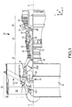
- Gas turbine engine 20 may be a two-spool turbofan that generally incorporates a fan section 22, a compressor section 24, a combustor section 26 and a turbine section 28.
- Alternative engines may include, for example, an augmentor section among other systems or features.
- fan section 22 can drive coolant (e.g., air) along a bypass flow-path B while compressor section 24 can drive air along a core flow-path C for compression and communication into combustor section 26 then expansion through turbine section 28.
- coolant e.g., air
- compressor section 24 can drive air along a core flow-path C for compression and communication into combustor section 26 then expansion through turbine section 28.
- three-spool architectures may also be included.
- Gas turbine engine 20 may generally comprise a low speed spool 30 and a high speed spool 32 mounted for rotation about an engine central longitudinal axis A-A' relative to an engine static structure 36 or engine case via several bearing systems 38, 38-1, and 38-2.
- Engine central longitudinal axis A-A' is oriented in the z direction on the provided xyz axis. It should be understood that various bearing systems 38 at various locations may alternatively or additionally be provided, including for example, bearing system 38, bearing system 38-1, and bearing system 38-2.
- Low speed spool 30 may generally comprise an inner shaft 40 that interconnects a low pressure compressor 44 and a low pressure turbine 46.
- Inner shaft 40 may be connected to fan 42 through a geared architecture 48 that can drive fan 42 at a lower speed than low speed spool 30.
- Geared architecture 48 may comprise a gear assembly 60 enclosed within a gear housing 62.
- Gear assembly 60 couples inner shaft 40 to a rotating fan structure.
- High speed spool 32 may comprise an outer shaft 50 that interconnects a high pressure compressor 52 and high pressure turbine 54.
- a combustor 56 may be located between high pressure compressor 52 and high pressure turbine 54.
- the combustor section 26 may have an annular wall assembly having inner and outer shells that support respective inner and outer heat shielding liners.
- the heat shield liners may include a plurality of combustor panels that collectively define the annular combustion chamber of the combustor 56.
- An annular cooling cavity is defined between the respective shells and combustor panels for supplying cooling air. Impingement holes are located in the shell to supply the cooling air from an outer air plenum and into the annular cooling cavity.
- a mid-turbine frame 57 of engine static structure 36 may be located generally between high pressure turbine 54 and low pressure turbine 46.
- Mid-turbine frame 57 may support one or more bearing systems 38 in turbine section 28.
- Inner shaft 40 and outer shaft 50 may be concentric and rotate via bearing systems 38 about the engine central longitudinal axis A-A', which is collinear with their longitudinal axes.
- a "high pressure" compressor or turbine experiences a higher pressure than a corresponding "low pressure” compressor or turbine.
- the core airflow C may be compressed by low pressure compressor 44 then high pressure compressor 52, mixed and burned with fuel in combustor 56, then expanded over high pressure turbine 54 and low pressure turbine 46.
- Turbines 46, 54 rotationally drive the respective low speed spool 30 and high speed spool 32 in response to the expansion.
- geared architecture 48 may be an epicyclical gear train, such as a star gear system (sun gear in meshing engagement with a plurality of star gears supported by a carrier and in meshing engagement with a ring gear) or other gear system.
- Geared architecture 48 may have a gear reduction ratio of greater than about 2.3 and low pressure turbine 46 may have a pressure ratio that is greater than about five (5).
- the bypass ratio of gas turbine engine 20 is greater than about ten (10:1).
- the diameter of fan 42 may be significantly larger than that of the low pressure compressor 44, and the low pressure turbine 46 may have a pressure ratio that is greater than about five (5:1).
- Low pressure turbine 46 pressure ratio may be measured prior to inlet of low pressure turbine 46 as related to the pressure at the outlet of low pressure turbine 46 prior to an exhaust nozzle. It should be understood, however, that the above parameters are exemplary of various embodiments of a suitable geared architecture engine and that the present disclosure contemplates other gas turbine engines including direct drive turbofans.
- a gas turbine engine may comprise an industrial gas turbine (IGT) or a geared aircraft engine, such as a geared turbofan, or non-geared aircraft engine, such as a turbofan, or may comprise any gas turbine engine as desired.
- IGT industrial gas turbine
- a geared aircraft engine such as a geared turbofan
- non-geared aircraft engine such as a turbofan
- fluid film damper system 200 comprises a support housing 210 disposed about a cylindrical internal member 212 which is subject to attempted cyclical orbital motion 214.
- Support housing 210 may be an annular support housing.
- Cylindrical internal member 212 may be a nonrotating bearing sleeve, hereinafter referred to as the sleeve 212.
- a flow of damping fluid is introduced into the annular volume 216 formed between the inner surface 218 of the support housing 210 and the outer nonrotating surface 220 of the sleeve 212 via a supply conduit (also referred to herein as a first supply conduit) 222 and supply conduit (also referred to herein as a second supply conduit) 224.
- Supply conduit 222 and supply conduit 224 may receive oil from a common oil supply conduit 240.
- Common oil supply conduit 240 may comprise a check valve 242 to prevent back flow from annular volume 216 to common oil supply conduit 240.
- the fluid may fill the annular volume 216.
- the damper thus described absorbs the momentum of the sleeve 212 through viscous and hydro-dynamically created forces resulting from the presence of the damping fluid in the annular volume 216.
- the orbital motion 214 of the sleeve 212 causes a circumferential pressure wave to be propagated around the inner surface 218 in advance of the orbiting line of closest approach 226 between the sleeve 212 and the support housing 210.
- the local fluid pressure reaches a maximum within the circumferential pressure wave which when resolved into component forces produces a spring force, thereby exerting a substantial radial opposing force on the sleeve 212 and preventing undesirable contact between the sleeve 212 and inner surface 218 and a damping force which opposes the orbiting motion.
- FIG. 2A illustrates sleeve 212 at a first position of its orbit
- FIG. 2B illustrates sleeve 212 at a second position of its orbit.
- Fluid pressure may be maintained within the annular volume 216 by providing check valve 242.
- supply conduit 222 and supply conduit 224 may be sized to regulate the volume flow of damping fluid through the supply conduits 222, 224, as well as to maintain the fluid pressure within the annular volume 216 as high as practicable to prevent separation of dissolved air in the moving low pressure zone.
- the dynamic operating pressures of the annular volume 216 may be in the range of 500 to 2.000 pounds per square inch (3.450 to 13,800 kPa).
- supply conduit 222 supplies oil to a first inlet 223 to annular volume 216 and supply conduit 224 supplies oil to a second inlet 225 to annular volume 216.
- First inlet 223 is disposed opposite the annular volume 216 from second inlet 225.
- First inlet 223 may be disposed one hundred and eighty degrees (180°) around the annular volume 216 from second inlet 225.
- the pressure acting at supply conduit 222 attempts to oscillate, similar to that of a sin wave.
- the pressure acting at supply conduit 224 attempts to oscillate, similar to that of a sin wave, equal and opposite to the pressure acting at supply conduit 222.
- annular volume 216, supply conduit 222, and supply conduit 224 may define a full loop flow path 280.
- Full loop flow path 280 may be generally free of obstructions (e.g., a valve).
- FIG. 2B as the pressure at supply conduit 222 increases, oil and/or oil pressure may be communicated from annular volume 216, into supply conduit 222, through supply conduit 224 and back into annular volume 216 (see arrows 292).
- full loop flow path 280 tends to minimize pressure fluctuations in supply conduit 222 and supply conduit 224.
- first inlet 223 by coupling first inlet 223 to second inlet 225 via first supply conduit 222 and second supply conduit 224, the relatively high pressure at second inlet 225 is effectively canceled by the relatively low pressure at first inlet 223.
- first inlet 223 by coupling first inlet 223 to second inlet 225 via first supply conduit 222 and second supply conduit 224, the relatively low pressure at second inlet 225 is effectively canceled by the relatively high pressure at first inlet 223
- the full loop configuration of supply conduit 222 and supply conduit 224 may tend to minimize the pressure experienced by check valve 242.
- supply conduit 222 and supply conduit 224 may be sized such that the flow path length through supply conduit 222, between check valve 242 and annular volume 216, is equal to the flow path length through supply conduit 224, between check valve 242 and annular volume 216.
- check valve 242 may be coupled half way between first inlet 223 and second inlet 225.
- common oil supply conduit 240 may be split into two equal length supply paths (i.e., supply conduit 222 and supply conduit 224) in fluid communication with annular volume 216. In this manner, the pressure fluctuations (e.g., spikes in pressure) experienced by check valve 242 may tend to be minimized.
- common oil supply conduit 240 is connected in series with supply conduit 222 and supply conduit 224. In various embodiments, supply conduit 222 and supply conduit 224 are coupled in parallel between common oil supply conduit 240 and annular volume 216.
- Fluid damper 300 may be supplied with oil from fluid supply 302, comprising supply conduit 222, supply conduit 224, common oil supply conduit 240 and check valve 242.
- the annular volume 316 is shown between the cylinder surface 320 and the inner surface 318 of the support housing 310. Longitudinal flow of damping fluid from the annular volume 316 is prevented by longitudinal seals 344, 346. Longitudinal seals 344, 346 may be any suitable seal including elastomeric O-rings, among others.
- Cylindrical member 312 may be a nonrotating bearing sleeve mounted over a bearing 338.
- Rotating shaft 350 may be supported by bearing 338.
- the orbital motion 214 (see FIG. 2A and FIG. 2B ) may be excited by a vibration of shaft 350.
- Supply conduit 222 may be coupled to support housing 310.
- First inlet 323 may comprise a channel or orifice disposed through support housing 310.
- Supply conduit 224 may be coupled to support housing 310.
- Second inlet 325 may comprise a channel or orifice disposed through support housing 310.
- supply conduit 222 and supply conduit 224 may be integral to support housing 310, for example as described with respect to FIG. 5 herein.
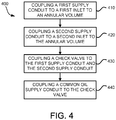
- Method 400 includes coupling a first supply conduit to a first inlet to an annular volume (step 410).
- Method 400 includes coupling a second supply conduit to a second inlet to the annular volume (step 420).
- Method 400 includes coupling a check valve to the first supply conduit and the second supply conduit (step 430).
- Method 400 includes coupling a common oil supply conduit to the check valve (step 440).
- Step 410 may include coupling first supply conduit 222 to first inlet 323 to annular volume 316.
- Step 420 may include coupling second supply conduit 224 to second inlet 325 to annular volume 316.
- Step 430 may include coupling check valve 242 to be in fluid communication with first supply conduit 222 and second supply conduit 224, whereby a fluid is supplied to first supply conduit 222 and second supply conduit 224.
- Step 440 may include coupling common oil supply conduit 240 to check valve 242, whereby the fluid is supplied to first supply conduit 222 and second supply conduit 224 via check valve 242.
- a supply conduit 522, a supply conduit 524, a first inlet 523, and a second inlet 525 may be formed into support housing 510.
- supply conduit 522, supply conduit 524, first inlet 523, and second inlet 525 may be similar to supply conduit 222, supply conduit 224, first inlet 323, and second inlet 325, respectively, as described in FIG. 3 .
- check valve 242 may be coupled to support housing 510 via a single common oil supply conduit 240 routed from the check valve 242 to the support housing 510, as opposed to two separate supply conduits (e.g., supply conduit 222 and supply conduit 224) being routed therebetween.
- supply conduit 522, supply conduit 524, first inlet 523, and second inlet 525 may comprise channels formed into support housing 510.
- Supply conduit 522, supply conduit 524, first inlet 523, and/or second inlet 525 may be formed into support housing 510 via any suitable manufacturing technique, such as drilling, milling, or casting, among others.
- references to "various embodiments”, “one embodiment”, “an embodiment”, “an example embodiment”, etc. indicate that the embodiment described may include a particular feature, structure, or characteristic, but every embodiment may not necessarily include the particular feature, structure, or characteristic. Moreover, such phrases are not necessarily referring to the same embodiment. Further, when a particular feature, structure, or characteristic is described in connection with an embodiment, it is submitted that it is within the knowledge of one skilled in the art to affect such feature, structure, or characteristic in connection with other embodiments whether or not explicitly described. After reading the description, it will be apparent to one skilled in the relevant art(s) how to implement the disclosure in alternative embodiments.
Landscapes
- Engineering & Computer Science (AREA)
- General Engineering & Computer Science (AREA)
- Mechanical Engineering (AREA)
- Chemical & Material Sciences (AREA)
- Combustion & Propulsion (AREA)
- Support Of The Bearing (AREA)
Applications Claiming Priority (1)
| Application Number | Priority Date | Filing Date | Title |
|---|---|---|---|
| US16/035,391 US10641327B2 (en) | 2018-07-13 | 2018-07-13 | Oil supply system for fluid film damper |
Publications (3)
| Publication Number | Publication Date |
|---|---|
| EP3594530A1 true EP3594530A1 (de) | 2020-01-15 |
| EP3594530B1 EP3594530B1 (de) | 2021-02-24 |
| EP3594530B8 EP3594530B8 (de) | 2021-04-07 |
Family
ID=67262201
Family Applications (1)
| Application Number | Title | Priority Date | Filing Date |
|---|---|---|---|
| EP19186096.4A Active EP3594530B8 (de) | 2018-07-13 | 2019-07-12 | Ölversorgungssystem für fluidfilmdämpfer |
Country Status (2)
| Country | Link |
|---|---|
| US (1) | US10641327B2 (de) |
| EP (1) | EP3594530B8 (de) |
Cited By (1)
| Publication number | Priority date | Publication date | Assignee | Title |
|---|---|---|---|---|
| CN111692211A (zh) * | 2020-06-22 | 2020-09-22 | 奚志娴 | 带有挤压油膜阻尼器的磁悬浮轴承 |
Families Citing this family (3)
| Publication number | Priority date | Publication date | Assignee | Title |
|---|---|---|---|---|
| US10808753B1 (en) * | 2019-06-03 | 2020-10-20 | Raytheon Technologies Corporation | Method and apparatus for mounting multiple bearings on a shaft |
| US11971054B2 (en) | 2020-10-19 | 2024-04-30 | General Electric Company | Damping device for damping shaft vibration |
| US20260103996A1 (en) * | 2024-10-16 | 2026-04-16 | Honeywell International Inc. | Damping and centering system for rotating machinery |
Citations (3)
| Publication number | Priority date | Publication date | Assignee | Title |
|---|---|---|---|---|
| US5344239A (en) * | 1992-11-25 | 1994-09-06 | General Electric Company | Squeeze film bearing damper with annular end plenums |
| US6135639A (en) * | 1998-12-28 | 2000-10-24 | General Electric Company | Fixed arc squeeze film bearing damper |
| WO2014130121A1 (en) * | 2013-02-24 | 2014-08-28 | Copeland Andrew D | Shaft displacement control |
Family Cites Families (11)
| Publication number | Priority date | Publication date | Assignee | Title |
|---|---|---|---|---|
| US3678382A (en) * | 1970-04-09 | 1972-07-18 | Coulter Electronics | Malfunction detection circuit and method |
| US4775248A (en) | 1987-12-16 | 1988-10-04 | United Technologies Corporation | Multiple feed oil supply system for fluid damper |
| US4782919A (en) * | 1987-12-21 | 1988-11-08 | United Technologies Corporation | Supply system for oil dampers |
| US5207511A (en) | 1991-07-22 | 1993-05-04 | General Electric Company | Squeeze film damper oil control |
| US5251985A (en) * | 1991-09-26 | 1993-10-12 | General Electric Company | Squeeze film damper seal |
| US5169241A (en) | 1991-10-04 | 1992-12-08 | General Electric Company | Squeeze film shaft damper oil system |
| US8858173B2 (en) | 2011-05-04 | 2014-10-14 | Honeywell International Inc. | Bearing assembly with damping features |
| US20130294917A1 (en) | 2012-05-07 | 2013-11-07 | Honeywell International Inc. | Apparatuses including a rotor group and methods of damping the apparatuses |
| US9494048B1 (en) | 2015-05-12 | 2016-11-15 | United Technologies Corporation | Active system for bearing oil damper supply and vibration control |
| US10436064B2 (en) | 2016-02-12 | 2019-10-08 | United Technologies Corporation | Bowed rotor start response damping system |
| US10458278B2 (en) | 2016-11-04 | 2019-10-29 | United Technologies Corporation | Apparatus and method for providing fluid to a bearing damper |
-
2018
- 2018-07-13 US US16/035,391 patent/US10641327B2/en active Active
-
2019
- 2019-07-12 EP EP19186096.4A patent/EP3594530B8/de active Active
Patent Citations (3)
| Publication number | Priority date | Publication date | Assignee | Title |
|---|---|---|---|---|
| US5344239A (en) * | 1992-11-25 | 1994-09-06 | General Electric Company | Squeeze film bearing damper with annular end plenums |
| US6135639A (en) * | 1998-12-28 | 2000-10-24 | General Electric Company | Fixed arc squeeze film bearing damper |
| WO2014130121A1 (en) * | 2013-02-24 | 2014-08-28 | Copeland Andrew D | Shaft displacement control |
Cited By (1)
| Publication number | Priority date | Publication date | Assignee | Title |
|---|---|---|---|---|
| CN111692211A (zh) * | 2020-06-22 | 2020-09-22 | 奚志娴 | 带有挤压油膜阻尼器的磁悬浮轴承 |
Also Published As
| Publication number | Publication date |
|---|---|
| US10641327B2 (en) | 2020-05-05 |
| EP3594530B1 (de) | 2021-02-24 |
| US20200018350A1 (en) | 2020-01-16 |
| EP3594530B8 (de) | 2021-04-07 |
Similar Documents
| Publication | Publication Date | Title |
|---|---|---|
| EP3719265B1 (de) | Rotierende kohlenstoffkolbenringdichtung | |
| EP3594530B1 (de) | Ölversorgungssystem für fluidfilmdämpfer | |
| JP5969319B2 (ja) | 環状ベアリング支持ダンパ、これを含むガスタービンエンジン、およびこれらの製造方法 | |
| EP3636883B1 (de) | Dichtungsanordnung mit schwingungsdämpfenden borsten | |
| US9726031B2 (en) | Piston ring coated carbon seal | |
| US10443436B2 (en) | Modular annular heat exchanger | |
| US10240529B2 (en) | Gas turbine engine aft bearing arrangement | |
| EP3670860B1 (de) | Bläser und niederdruckverdichter, die an die niedergeschwindigkeitsspule einer gasturbine gekoppelt sind | |
| JP5991865B2 (ja) | ガスタービンエンジンおよびガスタービンエンジン用の一体型ケース/ステータセグメント | |
| US9546560B2 (en) | Compact double grounded mechanical carbon seal | |
| US10788131B2 (en) | Face seal arrangement | |
| US9335052B2 (en) | Cross-fire tube mounting assembly for a gas turbine engine combustor | |
| US11473431B2 (en) | Energy dissipating damper | |
| EP3255326B1 (de) | Doppelwandiges rohr und herstellung davon | |
| EP3049655A1 (de) | Lageranordnung für einen gasturbinenmotor | |
| US20180291756A1 (en) | Ring seal arrangement | |
| EP3239545B1 (de) | Integriertes ölversorgungsrohr und rückschlagventil | |
| EP3447249B1 (de) | Abdichtungskonfigurationen mit aktiven kühlungsmerkmalen | |
| US10557572B2 (en) | Conduit with damping fingers | |
| EP3282101B1 (de) | Unterlegscheibe für gasturbinenmotor | |
| EP3835606B1 (de) | Feder zur zentrierung eines gekrümmten trägers für ein drucklager | |
| US10767867B2 (en) | Bearing support assembly | |
| US20250314207A1 (en) | Turbine engine gearbox assembly |
Legal Events
| Date | Code | Title | Description |
|---|---|---|---|
| PUAI | Public reference made under article 153(3) epc to a published international application that has entered the european phase |
Free format text: ORIGINAL CODE: 0009012 |
|
| STAA | Information on the status of an ep patent application or granted ep patent |
Free format text: STATUS: THE APPLICATION HAS BEEN PUBLISHED |
|
| AK | Designated contracting states |
Kind code of ref document: A1 Designated state(s): AL AT BE BG CH CY CZ DE DK EE ES FI FR GB GR HR HU IE IS IT LI LT LU LV MC MK MT NL NO PL PT RO RS SE SI SK SM TR |
|
| AX | Request for extension of the european patent |
Extension state: BA ME |
|
| STAA | Information on the status of an ep patent application or granted ep patent |
Free format text: STATUS: REQUEST FOR EXAMINATION WAS MADE |
|
| 17P | Request for examination filed |
Effective date: 20200714 |
|
| RBV | Designated contracting states (corrected) |
Designated state(s): AL AT BE BG CH CY CZ DE DK EE ES FI FR GB GR HR HU IE IS IT LI LT LU LV MC MK MT NL NO PL PT RO RS SE SI SK SM TR |
|
| GRAP | Despatch of communication of intention to grant a patent |
Free format text: ORIGINAL CODE: EPIDOSNIGR1 |
|
| STAA | Information on the status of an ep patent application or granted ep patent |
Free format text: STATUS: GRANT OF PATENT IS INTENDED |
|
| INTG | Intention to grant announced |
Effective date: 20200827 |
|
| GRAS | Grant fee paid |
Free format text: ORIGINAL CODE: EPIDOSNIGR3 |
|
| GRAA | (expected) grant |
Free format text: ORIGINAL CODE: 0009210 |
|
| STAA | Information on the status of an ep patent application or granted ep patent |
Free format text: STATUS: THE PATENT HAS BEEN GRANTED |
|
| AK | Designated contracting states |
Kind code of ref document: B1 Designated state(s): AL AT BE BG CH CY CZ DE DK EE ES FI FR GB GR HR HU IE IS IT LI LT LU LV MC MK MT NL NO PL PT RO RS SE SI SK SM TR |
|
| REG | Reference to a national code |
Ref country code: CH Ref legal event code: EP |
|
| REG | Reference to a national code |
Ref country code: DE Ref legal event code: R081 Ref document number: 602019002747 Country of ref document: DE Owner name: RAYTHEON TECHNOLOGIES CORPORATION, FARMINGTON, US Free format text: FORMER OWNER: UNITED TECHNOLOGIES CORPORATION, FARMINGTON, CONN., US Ref country code: DE Ref legal event code: R081 Ref document number: 602019002747 Country of ref document: DE Owner name: RTX CORPORATION (N.D.GES.D. STAATES DELAWARE),, US Free format text: FORMER OWNER: UNITED TECHNOLOGIES CORPORATION, FARMINGTON, CONN., US |
|
| REG | Reference to a national code |
Ref country code: CH Ref legal event code: PK Free format text: BERICHTIGUNG B8 Ref country code: AT Ref legal event code: REF Ref document number: 1364841 Country of ref document: AT Kind code of ref document: T Effective date: 20210315 |
|
| REG | Reference to a national code |
Ref country code: IE Ref legal event code: FG4D |
|
| REG | Reference to a national code |
Ref country code: DE Ref legal event code: R096 Ref document number: 602019002747 Country of ref document: DE |
|
| RAP2 | Party data changed (patent owner data changed or rights of a patent transferred) |
Owner name: RAYTHEON TECHNOLOGIES CORPORATION |
|
| REG | Reference to a national code |
Ref country code: LT Ref legal event code: MG9D |
|
| REG | Reference to a national code |
Ref country code: NL Ref legal event code: MP Effective date: 20210224 |
|
| PG25 | Lapsed in a contracting state [announced via postgrant information from national office to epo] |
Ref country code: NO Free format text: LAPSE BECAUSE OF FAILURE TO SUBMIT A TRANSLATION OF THE DESCRIPTION OR TO PAY THE FEE WITHIN THE PRESCRIBED TIME-LIMIT Effective date: 20210524 Ref country code: PT Free format text: LAPSE BECAUSE OF FAILURE TO SUBMIT A TRANSLATION OF THE DESCRIPTION OR TO PAY THE FEE WITHIN THE PRESCRIBED TIME-LIMIT Effective date: 20210624 Ref country code: LT Free format text: LAPSE BECAUSE OF FAILURE TO SUBMIT A TRANSLATION OF THE DESCRIPTION OR TO PAY THE FEE WITHIN THE PRESCRIBED TIME-LIMIT Effective date: 20210224 Ref country code: FI Free format text: LAPSE BECAUSE OF FAILURE TO SUBMIT A TRANSLATION OF THE DESCRIPTION OR TO PAY THE FEE WITHIN THE PRESCRIBED TIME-LIMIT Effective date: 20210224 Ref country code: GR Free format text: LAPSE BECAUSE OF FAILURE TO SUBMIT A TRANSLATION OF THE DESCRIPTION OR TO PAY THE FEE WITHIN THE PRESCRIBED TIME-LIMIT Effective date: 20210525 Ref country code: BG Free format text: LAPSE BECAUSE OF FAILURE TO SUBMIT A TRANSLATION OF THE DESCRIPTION OR TO PAY THE FEE WITHIN THE PRESCRIBED TIME-LIMIT Effective date: 20210524 Ref country code: HR Free format text: LAPSE BECAUSE OF FAILURE TO SUBMIT A TRANSLATION OF THE DESCRIPTION OR TO PAY THE FEE WITHIN THE PRESCRIBED TIME-LIMIT Effective date: 20210224 |
|
| REG | Reference to a national code |
Ref country code: AT Ref legal event code: MK05 Ref document number: 1364841 Country of ref document: AT Kind code of ref document: T Effective date: 20210224 |
|
| PG25 | Lapsed in a contracting state [announced via postgrant information from national office to epo] |
Ref country code: PL Free format text: LAPSE BECAUSE OF FAILURE TO SUBMIT A TRANSLATION OF THE DESCRIPTION OR TO PAY THE FEE WITHIN THE PRESCRIBED TIME-LIMIT Effective date: 20210224 Ref country code: NL Free format text: LAPSE BECAUSE OF FAILURE TO SUBMIT A TRANSLATION OF THE DESCRIPTION OR TO PAY THE FEE WITHIN THE PRESCRIBED TIME-LIMIT Effective date: 20210224 Ref country code: LV Free format text: LAPSE BECAUSE OF FAILURE TO SUBMIT A TRANSLATION OF THE DESCRIPTION OR TO PAY THE FEE WITHIN THE PRESCRIBED TIME-LIMIT Effective date: 20210224 Ref country code: RS Free format text: LAPSE BECAUSE OF FAILURE TO SUBMIT A TRANSLATION OF THE DESCRIPTION OR TO PAY THE FEE WITHIN THE PRESCRIBED TIME-LIMIT Effective date: 20210224 Ref country code: SE Free format text: LAPSE BECAUSE OF FAILURE TO SUBMIT A TRANSLATION OF THE DESCRIPTION OR TO PAY THE FEE WITHIN THE PRESCRIBED TIME-LIMIT Effective date: 20210224 |
|
| PG25 | Lapsed in a contracting state [announced via postgrant information from national office to epo] |
Ref country code: IS Free format text: LAPSE BECAUSE OF FAILURE TO SUBMIT A TRANSLATION OF THE DESCRIPTION OR TO PAY THE FEE WITHIN THE PRESCRIBED TIME-LIMIT Effective date: 20210624 |
|
| PG25 | Lapsed in a contracting state [announced via postgrant information from national office to epo] |
Ref country code: EE Free format text: LAPSE BECAUSE OF FAILURE TO SUBMIT A TRANSLATION OF THE DESCRIPTION OR TO PAY THE FEE WITHIN THE PRESCRIBED TIME-LIMIT Effective date: 20210224 Ref country code: CZ Free format text: LAPSE BECAUSE OF FAILURE TO SUBMIT A TRANSLATION OF THE DESCRIPTION OR TO PAY THE FEE WITHIN THE PRESCRIBED TIME-LIMIT Effective date: 20210224 Ref country code: AT Free format text: LAPSE BECAUSE OF FAILURE TO SUBMIT A TRANSLATION OF THE DESCRIPTION OR TO PAY THE FEE WITHIN THE PRESCRIBED TIME-LIMIT Effective date: 20210224 Ref country code: SM Free format text: LAPSE BECAUSE OF FAILURE TO SUBMIT A TRANSLATION OF THE DESCRIPTION OR TO PAY THE FEE WITHIN THE PRESCRIBED TIME-LIMIT Effective date: 20210224 |
|
| REG | Reference to a national code |
Ref country code: DE Ref legal event code: R097 Ref document number: 602019002747 Country of ref document: DE |
|
| PG25 | Lapsed in a contracting state [announced via postgrant information from national office to epo] |
Ref country code: DK Free format text: LAPSE BECAUSE OF FAILURE TO SUBMIT A TRANSLATION OF THE DESCRIPTION OR TO PAY THE FEE WITHIN THE PRESCRIBED TIME-LIMIT Effective date: 20210224 Ref country code: RO Free format text: LAPSE BECAUSE OF FAILURE TO SUBMIT A TRANSLATION OF THE DESCRIPTION OR TO PAY THE FEE WITHIN THE PRESCRIBED TIME-LIMIT Effective date: 20210224 Ref country code: SK Free format text: LAPSE BECAUSE OF FAILURE TO SUBMIT A TRANSLATION OF THE DESCRIPTION OR TO PAY THE FEE WITHIN THE PRESCRIBED TIME-LIMIT Effective date: 20210224 |
|
| PLBE | No opposition filed within time limit |
Free format text: ORIGINAL CODE: 0009261 |
|
| STAA | Information on the status of an ep patent application or granted ep patent |
Free format text: STATUS: NO OPPOSITION FILED WITHIN TIME LIMIT |
|
| PG25 | Lapsed in a contracting state [announced via postgrant information from national office to epo] |
Ref country code: AL Free format text: LAPSE BECAUSE OF FAILURE TO SUBMIT A TRANSLATION OF THE DESCRIPTION OR TO PAY THE FEE WITHIN THE PRESCRIBED TIME-LIMIT Effective date: 20210224 Ref country code: ES Free format text: LAPSE BECAUSE OF FAILURE TO SUBMIT A TRANSLATION OF THE DESCRIPTION OR TO PAY THE FEE WITHIN THE PRESCRIBED TIME-LIMIT Effective date: 20210224 |
|
| 26N | No opposition filed |
Effective date: 20211125 |
|
| PG25 | Lapsed in a contracting state [announced via postgrant information from national office to epo] |
Ref country code: SI Free format text: LAPSE BECAUSE OF FAILURE TO SUBMIT A TRANSLATION OF THE DESCRIPTION OR TO PAY THE FEE WITHIN THE PRESCRIBED TIME-LIMIT Effective date: 20210224 |
|
| PG25 | Lapsed in a contracting state [announced via postgrant information from national office to epo] |
Ref country code: MC Free format text: LAPSE BECAUSE OF FAILURE TO SUBMIT A TRANSLATION OF THE DESCRIPTION OR TO PAY THE FEE WITHIN THE PRESCRIBED TIME-LIMIT Effective date: 20210224 |
|
| REG | Reference to a national code |
Ref country code: BE Ref legal event code: MM Effective date: 20210731 |
|
| PG25 | Lapsed in a contracting state [announced via postgrant information from national office to epo] |
Ref country code: IT Free format text: LAPSE BECAUSE OF FAILURE TO SUBMIT A TRANSLATION OF THE DESCRIPTION OR TO PAY THE FEE WITHIN THE PRESCRIBED TIME-LIMIT Effective date: 20210224 |
|
| PG25 | Lapsed in a contracting state [announced via postgrant information from national office to epo] |
Ref country code: IS Free format text: LAPSE BECAUSE OF FAILURE TO SUBMIT A TRANSLATION OF THE DESCRIPTION OR TO PAY THE FEE WITHIN THE PRESCRIBED TIME-LIMIT Effective date: 20210624 Ref country code: LU Free format text: LAPSE BECAUSE OF NON-PAYMENT OF DUE FEES Effective date: 20210712 |
|
| PG25 | Lapsed in a contracting state [announced via postgrant information from national office to epo] |
Ref country code: IE Free format text: LAPSE BECAUSE OF NON-PAYMENT OF DUE FEES Effective date: 20210712 Ref country code: BE Free format text: LAPSE BECAUSE OF NON-PAYMENT OF DUE FEES Effective date: 20210731 |
|
| REG | Reference to a national code |
Ref country code: CH Ref legal event code: PL |
|
| PG25 | Lapsed in a contracting state [announced via postgrant information from national office to epo] |
Ref country code: LI Free format text: LAPSE BECAUSE OF NON-PAYMENT OF DUE FEES Effective date: 20220731 Ref country code: CH Free format text: LAPSE BECAUSE OF NON-PAYMENT OF DUE FEES Effective date: 20220731 |
|
| P01 | Opt-out of the competence of the unified patent court (upc) registered |
Effective date: 20230521 |
|
| PG25 | Lapsed in a contracting state [announced via postgrant information from national office to epo] |
Ref country code: CY Free format text: LAPSE BECAUSE OF FAILURE TO SUBMIT A TRANSLATION OF THE DESCRIPTION OR TO PAY THE FEE WITHIN THE PRESCRIBED TIME-LIMIT Effective date: 20210224 |
|
| PG25 | Lapsed in a contracting state [announced via postgrant information from national office to epo] |
Ref country code: HU Free format text: LAPSE BECAUSE OF FAILURE TO SUBMIT A TRANSLATION OF THE DESCRIPTION OR TO PAY THE FEE WITHIN THE PRESCRIBED TIME-LIMIT; INVALID AB INITIO Effective date: 20190712 |
|
| PG25 | Lapsed in a contracting state [announced via postgrant information from national office to epo] |
Ref country code: MK Free format text: LAPSE BECAUSE OF FAILURE TO SUBMIT A TRANSLATION OF THE DESCRIPTION OR TO PAY THE FEE WITHIN THE PRESCRIBED TIME-LIMIT Effective date: 20210224 |
|
| PG25 | Lapsed in a contracting state [announced via postgrant information from national office to epo] |
Ref country code: MT Free format text: LAPSE BECAUSE OF FAILURE TO SUBMIT A TRANSLATION OF THE DESCRIPTION OR TO PAY THE FEE WITHIN THE PRESCRIBED TIME-LIMIT Effective date: 20210224 |
|
| PGFP | Annual fee paid to national office [announced via postgrant information from national office to epo] |
Ref country code: GB Payment date: 20250619 Year of fee payment: 7 |
|
| PGFP | Annual fee paid to national office [announced via postgrant information from national office to epo] |
Ref country code: FR Payment date: 20250620 Year of fee payment: 7 |
|
| REG | Reference to a national code |
Ref country code: DE Ref legal event code: R081 Ref document number: 602019002747 Country of ref document: DE Owner name: RTX CORPORATION (N.D.GES.D. STAATES DELAWARE),, US Free format text: FORMER OWNER: RAYTHEON TECHNOLOGIES CORPORATION, FARMINGTON, CT, US |
|
| PGFP | Annual fee paid to national office [announced via postgrant information from national office to epo] |
Ref country code: DE Payment date: 20250620 Year of fee payment: 7 |
|
| PG25 | Lapsed in a contracting state [announced via postgrant information from national office to epo] |
Ref country code: TR Free format text: LAPSE BECAUSE OF FAILURE TO SUBMIT A TRANSLATION OF THE DESCRIPTION OR TO PAY THE FEE WITHIN THE PRESCRIBED TIME-LIMIT Effective date: 20210224 |