EP3594443A2 - Wellbore tong - Google Patents
Wellbore tong Download PDFInfo
- Publication number
- EP3594443A2 EP3594443A2 EP19174001.8A EP19174001A EP3594443A2 EP 3594443 A2 EP3594443 A2 EP 3594443A2 EP 19174001 A EP19174001 A EP 19174001A EP 3594443 A2 EP3594443 A2 EP 3594443A2
- Authority
- EP
- European Patent Office
- Prior art keywords
- brake
- assembly
- brake plate
- gear ring
- band
- Prior art date
- Legal status (The legal status is an assumption and is not a legal conclusion. Google has not performed a legal analysis and makes no representation as to the accuracy of the status listed.)
- Granted
Links
Images



Classifications
-
- E—FIXED CONSTRUCTIONS
- E21—EARTH OR ROCK DRILLING; MINING
- E21B—EARTH OR ROCK DRILLING; OBTAINING OIL, GAS, WATER, SOLUBLE OR MELTABLE MATERIALS OR A SLURRY OF MINERALS FROM WELLS
- E21B19/00—Handling rods, casings, tubes or the like outside the borehole, e.g. in the derrick; Apparatus for feeding the rods or cables
- E21B19/16—Connecting or disconnecting pipe couplings or joints
- E21B19/165—Control or monitoring arrangements therefor
-
- E—FIXED CONSTRUCTIONS
- E21—EARTH OR ROCK DRILLING; MINING
- E21B—EARTH OR ROCK DRILLING; OBTAINING OIL, GAS, WATER, SOLUBLE OR MELTABLE MATERIALS OR A SLURRY OF MINERALS FROM WELLS
- E21B19/00—Handling rods, casings, tubes or the like outside the borehole, e.g. in the derrick; Apparatus for feeding the rods or cables
- E21B19/16—Connecting or disconnecting pipe couplings or joints
- E21B19/161—Connecting or disconnecting pipe couplings or joints using a wrench or a spinner adapted to engage a circular section of pipe
- E21B19/164—Connecting or disconnecting pipe couplings or joints using a wrench or a spinner adapted to engage a circular section of pipe motor actuated
Definitions
- Embodiments described herein generally relate to a tong for use at a wellbore.
- Wellbore tongs are well known in the art for making and breaking threaded connections between tubulars as strings are assembled or disassembled for use in a wellbore.
- a back-up or lower tong holds a tubular extending from the wellbore while an upper tong grasps and then rotates a new tubular into our out of the string.
- the upper tong includes a mechanism to grasp the tubular and then, in a separate step, rotates the tubular to perform threading or unthreading.
- the grasping step one rotating portion of the assembly must be held in place while the gripping assembly operates. Thereafter, both portions are rotated as a unit during the threading operation.
- an improved braking assembly to temporarily hold the rotating portion during the gripping step.
- the tong includes a gear ring powered by a motor assembly, the gear ring having a plurality of ramps formed on an inner surface thereof and a brake plate rotationally independent of the gear ring, the brake plate having a gripping assembly for interacting with the ramps to grip a tubular.
- the gripping assembly In a first position of the gear ring relative to the brake plate, the gripping assembly is open and in a second position the assembly grips the tubular.
- a brake assembly for preventing rotation of the brake plate, the brake assembly including an adjustable brake band for applying friction to the brake plate and at least one brake pad made of braking material disposed on an outer surface thereof in the area of contact with the brake band for reducing friction between the brake plate and the brake band.
- the braking material is bronze.
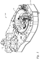
- FIG. 1 is a perspective view of a wellbore tong.
- the tong has two functions: it grasps a tubular (not shown) using a gripping assembly generally shown as 110 and thereafter, it rotates the tubular relative to a tubular therebelow in order to make or break a threaded connection therebetween.
- a door 120 shown in a closed position, permits the tubular to be inserted into the gripping assembly 110 of the tong 100.
- a hydraulic motor assembly generally shown as 130 rotates a gear ring (not visible) that is responsible for rotation of the tubular when a connection is made.
- a "cage" or brake plate 140 is rotatable independent of the gear ring.
- the gripping assembly 110 is associated with the rotatable brake plate 140 and rotates therewith. Separately, inwardly facing ramps (not visible) are formed on an inner surface of the gear ring.
- ramps are formed on an inner surface of the gear ring.
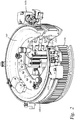
- Figure 2 is a perspective view of a portion of the tong 100 including the rotatable brake plate 140, the gripping assembly 110 rotatable therewith and a separately rotatable gear ring 150.
- the gear ring includes teeth formed on a perimeter thereof for engagement with corresponding teeth associated with the motor assembly 130 ( Figure 1 ).
- a braking assembly for the brake plate in order to stop its rotation during the gripping portion of the operation.
- the breaking assembly includes a brake band 160 that can be tightened thereby providing friction between the band 160 and the brake plate 140. The tightening takes place at each end of the band with piston-actuated braking members 165a, 165b.
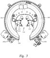
- Figure 3 is a top view of the assembly of Figure 2 showing gripping members 112, 115 that are a part of the gripping assembly 110. As illustrated, the gripping members can be actuated towards or away from the centerline of a tubular.
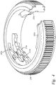
- Figure 4 is a perspective view of the gear ring 150 showing a plurality of ramps 205a, 210a, 215b formed on an inner surface thereof opposite an opening or throat of the ring.
- the upper and lower ramps 205a, 210a are constructed and arranged to operate with a set of double wheels 305, 310 ( Figure 5 ) in order to actuate one gripping member 115 of the gripping assembly 110 when a threaded connection is being made.
- the center ramp 215b as is evident by its direction is constructed and arranged to actuate a single wheel 315 associated with gripping member 112 when a connection between tubulars is being broken.
- An opposite group of ramps two of which 215a, 205b are visible in Figure 4 are responsible for a reverse arrangement wherein a second set of double ramps (upper ramp 205b is visible) operates with the double wheels 305, 310 to break a connection and a second single ramp 215a operates with the single wheel 315 when a connection is made.
- FIG. 5 is a perspective view of the gripping assembly 110 illustrating the double pair of wheels 305, 310 on a first side and the single wheel 315 on a second side.
- the gripping assembly 110 is made up of two gripping members 112, 115, each operating like a slip with an inner surface having a concave shape to match the outer surface of the tubular to be grasped by the tong 100.
- the gripping assembly 110 utilizes the single wheel 315 associated with one gripping member 112 and the two-wheel set 305, 310 operating with a second gripping member 115.
- the wheels (along with the brake plate 140) remain rotationally fixed while the gear ring 150 with its various ramps rotates to a position wherein each wheel has ridden up a ramp.
- the result is a clamping action forcing the gripping members 112, 115 into contact with the tubular to be grasped.
- the make or break nature of the operation determines which set of ramps is utilized by the wheels as the tubular is gripped.
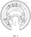
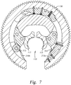
- Figure 6 is a top view partially in section, taken through one wheel 305 of the double pair of wheels 305, 310 and Figure 7 is a top view partially in section, taken through the single wheel 315.
- the gripping mechanism is deactivated, meaning that the wheels and ramps are not in contact with one another as indicated by the open position of the gripping members 112, 155 in each Figure.
- upper wheel 305 of the pair of wheels 305, 310 is visible above the ramp 215a that is designed to operate in conjunction with single wheel 315 when a connection is being broken.
- the single wheel 315 is visible with the lower ramp 210b below it.
- Figure 8 is a top view partially in section, taken through the single wheel 315 and showing the gripping assembly 110 actuated around a tubular 400. More specifically, Figure 8 is a top section view of the assembly shown in Figures 7 and 8 with the view taken through the single wheel 315. However, in Figure 8 the gear ring 150 with its sets of ramps has been rotated clockwise while the brake plate 140 and gripping assembly 110 have been rotationally held in the same orientation as they are in Figures 7 and 8 . The result is that the ramps have changed location relative to the wheels 305, 310, 315 in a manner whereby the wheels have mounted the ramps 215a, 205a, 210a that are designed to be utilized in actuating the gripping mechanism in order to make a connection. Because the wheels have been actuated by the ramps, the gripping mechanism 110 is actuated and the tubular 400 is gripped.
- Figure 9 is a top view partially in section, taken through the single wheel 315 and showing the tubular member 400 having been rotated in a clockwise direction to make a wellbore connection between tubulars. Comparing Figures 8 and 9 , in Figure 9 the entire tong unit including gear ring 150 and brake plate 140 has been rotated as a unit. In this manner the tubular 400 retained by the upper portion of the tong 100 is rotated relative to a tubular gripped by a lower portion (not shown) in order to make a threaded connection. It will be appreciated the operation can be reversed, using the same wheels but operating on another set of ramps having reverse formations. In this manner, the tong assembly can be used to make or break a threaded connection between tubulars.
- the brake plate 140 and gripping assembly must be rotationally fixed or at least rotationally limited relative to the gear ring while the gear ring 150 with its inwardly facing ramps rotates to a location whereby the ramps interact with the wheels of the gripping assembly to close the gripping members 112, 115 around a tubular 400. Thereafter, the gear wheel 150 and brake plate 140 rotate together to make or break a threaded connection. In one embodiment, rotation of the brake plate 140 is prevented with the use of a brake band 160 that is tightened around an outer surface of the plate in order to prevent its rotation.
- the brake band 160 and braking members 165a, b are shown in Figures 2 and 3 .
- the band 160 extends around an outer perimeter of the plate 140 and is held at each end by one of the braking members.
- the brake members can tighten the band 160 by urging each end towards the door 120 of the assembly, essentially removing slack in the band and thereby increasing its friction with the side of the brake plate 140.
- the braking members each include a piston that urges a corresponding end of the brake band 160 in order to tighten it.
- Figures 10 and 11 are top views showing the operation of one of the braking members 165b and its relationship with the brake plate 140.
- the brake is un-actuated as shown by a gap 146 formed between the band and an outer edge of a brake pad 145 disposed around an outer edge of the plate.
- Figure 11 is a similar view however, in Figure 11 the brake band has been tightened as apparent by the absence of gap 146 in the Figure.
- Arrow 149 illustrates the direction of a force placed upon the band in order to tighten it.
- One novel aspect of the invention relates to brake pads and their location relative to the brake band and brake plate.
- friction and heat generated between the tightened band and brake plate create wear and can cause failure of the entire tong assembly, essentially shutting down operations at a well site.
- brake material including non-metallic, semi metallic and ceramic materials has been used on an inner surface of the brake band in order to effect braking between the band and brake plate.
- grease is applied at the intersection of the band and plate. The addition of grease reduces the heat and wear but must be replaced regularly requiring precious time at the working wellsite.
- Figure 12 is a perspective view of the brake plate having apertures 142 around its perimeter for attachment of brake pads.
- One exemplary brake pad 145 is shown in the Figure.
- a braking surface is provided in a manner whereby the material is protected from the flexing of the brake band. Additionally, the pieces can be replaced in any area where excessive wear has occurred without replacing the entire band or a large strip of the braking material.
- the brake pads are constructed primarily of bronze or sintered bronze. Bronze is an alloy consisting primarily of copper, commonly with about 12% tin and often with the addition of other metals and sometimes non-metals or metalloids such as arsenic, phosphorus or silicon.
Landscapes
- Engineering & Computer Science (AREA)
- Life Sciences & Earth Sciences (AREA)
- Geology (AREA)
- Mining & Mineral Resources (AREA)
- Mechanical Engineering (AREA)
- Physics & Mathematics (AREA)
- Environmental & Geological Engineering (AREA)
- Fluid Mechanics (AREA)
- General Life Sciences & Earth Sciences (AREA)
- Geochemistry & Mineralogy (AREA)
- Braking Arrangements (AREA)
Abstract
Description
- Embodiments described herein generally relate to a tong for use at a wellbore.
- Wellbore tongs are well known in the art for making and breaking threaded connections between tubulars as strings are assembled or disassembled for use in a wellbore. Typically, a back-up or lower tong holds a tubular extending from the wellbore while an upper tong grasps and then rotates a new tubular into our out of the string. In most cases, the upper tong includes a mechanism to grasp the tubular and then, in a separate step, rotates the tubular to perform threading or unthreading. During the grasping step, one rotating portion of the assembly must be held in place while the gripping assembly operates. Thereafter, both portions are rotated as a unit during the threading operation. There is a need for an improved braking assembly to temporarily hold the rotating portion during the gripping step.
- The present disclosure generally concerns a wellbore tong. In one embodiment, the tong includes a gear ring powered by a motor assembly, the gear ring having a plurality of ramps formed on an inner surface thereof and a brake plate rotationally independent of the gear ring, the brake plate having a gripping assembly for interacting with the ramps to grip a tubular. In a first position of the gear ring relative to the brake plate, the gripping assembly is open and in a second position the assembly grips the tubular. Also included is a brake assembly for preventing rotation of the brake plate, the brake assembly including an adjustable brake band for applying friction to the brake plate and at least one brake pad made of braking material disposed on an outer surface thereof in the area of contact with the brake band for reducing friction between the brake plate and the brake band. In one embodiment, the braking material is bronze.
- So that the manner in which the above recited features of the present disclosure can be understood in detail, a more particular description of the disclosure, briefly summarized above, may be had by reference to embodiments, some of which are illustrated in the appended drawings. It is to be noted, however, that the appended drawings illustrate only typical embodiments of this disclosure and are therefore not to be considered limiting of its scope, for the disclosure may admit to other equally effective embodiments.
-
Figure 1 is a perspective view of a wellbore tong. -
Figure 2 is a perspective view of a portion of the tong including a rotatable brake plate, a gripping assembly rotatable therewith and a separately rotatable gear ring. -
Figure 3 is a top view of the assembly ofFigure 2 showing gripping members that are a part of the gripping assembly. -
Figure 4 is a perspective view of the gear ring showing a plurality of ramps formed on an inner surface thereof. -
Figure 5 is a perspective view of the gripping assembly illustrating a double pair of wheels on a first side and a single wheel on a second side. -
Figure 6 is a top view partially in section, taken through one wheel of the double pair of wheels. -
Figure 7 is a top view partially in section, taken through the single wheel. -
Figure 8 is a top view partially in section, taken through the single wheel and showing the gripping assembly actuated around a tubular. -
Figure 9 is a top view partially in section, taken through the single wheel and showing the tubular member having been rotated in a clockwise direction to make a wellbore connection between tubulars. -
Figures 10 and11 are top views of a braking member illustrating its operation in conjunction with a brake band to prevent rotation of the brake plate. -
Figure 12 is a perspective view of a brake plate illustrating the location of brake pads along an outer perimeter thereof. -
Figure 1 is a perspective view of a wellbore tong. The tong has two functions: it grasps a tubular (not shown) using a gripping assembly generally shown as 110 and thereafter, it rotates the tubular relative to a tubular therebelow in order to make or break a threaded connection therebetween. Adoor 120, shown in a closed position, permits the tubular to be inserted into thegripping assembly 110 of thetong 100. A hydraulic motor assembly generally shown as 130 rotates a gear ring (not visible) that is responsible for rotation of the tubular when a connection is made. Separately, a "cage" orbrake plate 140 is rotatable independent of the gear ring. In the embodiment shown, thegripping assembly 110 is associated with therotatable brake plate 140 and rotates therewith. Separately, inwardly facing ramps (not visible) are formed on an inner surface of the gear ring. To grip a tubular with thetong 100, it is necessary to rotationally fix thebrake plate 140 with itsgripping assembly 110 while rotating the gear ring in order to urge the ramps of the gear ring under a plurality of wheels associated with thegripping assembly 110. The action of the wheels and ramps acts to close grippingmembers brake plate 140 rotate together to make (or break) a connection. -
Figure 2 is a perspective view of a portion of thetong 100 including therotatable brake plate 140, thegripping assembly 110 rotatable therewith and a separatelyrotatable gear ring 150. The gear ring includes teeth formed on a perimeter thereof for engagement with corresponding teeth associated with the motor assembly 130 (Figure 1 ). Also shown inFigure 2 is a braking assembly for the brake plate in order to stop its rotation during the gripping portion of the operation. The breaking assembly, as will be described in additional detail herein, includes abrake band 160 that can be tightened thereby providing friction between theband 160 and thebrake plate 140. The tightening takes place at each end of the band with piston-actuatedbraking members -
Figure 3 is a top view of the assembly ofFigure 2 showing grippingmembers gripping assembly 110. As illustrated, the gripping members can be actuated towards or away from the centerline of a tubular. -
Figure 4 is a perspective view of thegear ring 150 showing a plurality oframps lower ramps double wheels 305, 310 (Figure 5 ) in order to actuate onegripping member 115 of thegripping assembly 110 when a threaded connection is being made. Thecenter ramp 215b, as is evident by its direction is constructed and arranged to actuate asingle wheel 315 associated with grippingmember 112 when a connection between tubulars is being broken. An opposite group of ramps, two of which 215a, 205b are visible inFigure 4 are responsible for a reverse arrangement wherein a second set of double ramps (upper ramp 205b is visible) operates with thedouble wheels single ramp 215a operates with thesingle wheel 315 when a connection is made. -
Figure 5 is a perspective view of thegripping assembly 110 illustrating the double pair ofwheels single wheel 315 on a second side. Thegripping assembly 110 is made up of twogripping members tong 100. As illustrated, thegripping assembly 110 utilizes thesingle wheel 315 associated with onegripping member 112 and the two-wheel set second gripping member 115. In operation, the wheels (along with the brake plate 140) remain rotationally fixed while thegear ring 150 with its various ramps rotates to a position wherein each wheel has ridden up a ramp. The result is a clamping action forcing the grippingmembers -
Figure 6 is a top view partially in section, taken through onewheel 305 of the double pair ofwheels Figure 7 is a top view partially in section, taken through thesingle wheel 315. In both Figures, the gripping mechanism is deactivated, meaning that the wheels and ramps are not in contact with one another as indicated by the open position of thegripping members 112, 155 in each Figure. For example, inFigure 6 ,upper wheel 305 of the pair ofwheels ramp 215a that is designed to operate in conjunction withsingle wheel 315 when a connection is being broken. Similarly inFigure 7 , on the left side of the Figure, thesingle wheel 315 is visible with thelower ramp 210b below it. -
Figure 8 is a top view partially in section, taken through thesingle wheel 315 and showing thegripping assembly 110 actuated around a tubular 400. More specifically,Figure 8 is a top section view of the assembly shown inFigures 7 and8 with the view taken through thesingle wheel 315. However, inFigure 8 thegear ring 150 with its sets of ramps has been rotated clockwise while thebrake plate 140 andgripping assembly 110 have been rotationally held in the same orientation as they are inFigures 7 and8 . The result is that the ramps have changed location relative to thewheels ramps gripping mechanism 110 is actuated and the tubular 400 is gripped. -
Figure 9 is a top view partially in section, taken through thesingle wheel 315 and showing thetubular member 400 having been rotated in a clockwise direction to make a wellbore connection between tubulars. ComparingFigures 8 and9 , inFigure 9 the entire tong unit includinggear ring 150 andbrake plate 140 has been rotated as a unit. In this manner the tubular 400 retained by the upper portion of thetong 100 is rotated relative to a tubular gripped by a lower portion (not shown) in order to make a threaded connection. It will be appreciated the operation can be reversed, using the same wheels but operating on another set of ramps having reverse formations. In this manner, the tong assembly can be used to make or break a threaded connection between tubulars. - As described above, in order to actuate the
gripping assembly 110, thebrake plate 140 and gripping assembly must be rotationally fixed or at least rotationally limited relative to the gear ring while thegear ring 150 with its inwardly facing ramps rotates to a location whereby the ramps interact with the wheels of the gripping assembly to close the grippingmembers gear wheel 150 andbrake plate 140 rotate together to make or break a threaded connection. In one embodiment, rotation of thebrake plate 140 is prevented with the use of abrake band 160 that is tightened around an outer surface of the plate in order to prevent its rotation. Thebrake band 160 andbraking members 165a, b are shown inFigures 2 and3 . As shown, theband 160 extends around an outer perimeter of theplate 140 and is held at each end by one of the braking members. By holding the band at each end, the brake members can tighten theband 160 by urging each end towards thedoor 120 of the assembly, essentially removing slack in the band and thereby increasing its friction with the side of thebrake plate 140. In one embodiment, the braking members each include a piston that urges a corresponding end of thebrake band 160 in order to tighten it. -
Figures 10 and11 are top views showing the operation of one of thebraking members 165b and its relationship with thebrake plate 140. InFigure 10 the brake is un-actuated as shown by agap 146 formed between the band and an outer edge of abrake pad 145 disposed around an outer edge of the plate.Figure 11 is a similar view however, inFigure 11 the brake band has been tightened as apparent by the absence ofgap 146 in the Figure.Arrow 149 illustrates the direction of a force placed upon the band in order to tighten it. - One novel aspect of the invention relates to brake pads and their location relative to the brake band and brake plate. In prior art devices, friction and heat generated between the tightened band and brake plate create wear and can cause failure of the entire tong assembly, essentially shutting down operations at a well site. In prior art devices, brake material including non-metallic, semi metallic and ceramic materials has been used on an inner surface of the brake band in order to effect braking between the band and brake plate. In order to extend the life of the brake band and to reduce friction and resulting heat between the surfaces, grease is applied at the intersection of the band and plate. The addition of grease reduces the heat and wear but must be replaced regularly requiring precious time at the working wellsite. Additionally, with or without grease, flexing of the band as it is tightened or loosened can cause the brake material to separate from the band. In one embodiment of the present invention, these problems and others are overcome by placing brake pads made of breaking and friction-reducing material not on the band but on the outer perimeter of the brake plate where it contacts the band.
-
Figure 12 is a perspective view of the brakeplate having apertures 142 around its perimeter for attachment of brake pads. Oneexemplary brake pad 145 is shown in the Figure. By fastening the brake pads with fasteners around the perimeter, a braking surface is provided in a manner whereby the material is protected from the flexing of the brake band. Additionally, the pieces can be replaced in any area where excessive wear has occurred without replacing the entire band or a large strip of the braking material. In one example, the brake pads are constructed primarily of bronze or sintered bronze. Bronze is an alloy consisting primarily of copper, commonly with about 12% tin and often with the addition of other metals and sometimes non-metals or metalloids such as arsenic, phosphorus or silicon. - While the foregoing is directed to embodiments of the present disclosure, other and further embodiments of the disclosure may be devised without departing from the basic scope thereof, and the scope thereof is determined by the claims that follow.
Claims (10)
- A tong for use at a wellbore, comprising:a gear ring powered by a motor assembly, the gear ring having a plurality of ramps formed on an inner surface thereof;a brake plate rotationally independent of the gear ring, the brake plate having a gripping assembly for interacting with the ramps to grip a tubular;wherein in a first position of the gear ring relative to the brake plate, the gripping assembly is open and in a second position the assembly grips the tubular;a brake assembly for preventing rotation of the brake plate, the brake assembly including an adjustable brake band for applying friction to the brake plate; andat least one brake pad disposed on an outer surface of the brake plate in the area of contact between the brake plate and the brake band.
- The tong of claim 1, wherein the pads are substantially constructed of bronze.
- The tong of claim 1 or 2, wherein the pads include a plurality of separate pads, each pad individually fastened to the brake plate.
- A method of making a threaded connection between tubulars at a wellbore, the method comprising:providing a tong assembly having a rotatable gear ring with ramps formed on an inner surface thereof;providing a brake plate, the brake plate rotatably independent of the gear ring and having a gripping assembly associated therewith;limiting rotation of the brake ring while rotating the gear ring, thereby causing the ramps of the gear ring to actuate the gripping assembly to grasp the tubular;permitting rotation of the brake plate with the gear ring to make the connection between the tubulars; whereinrotation of the brake plate is limited by a brake band, the brake band creating friction between an inner surface thereof and braking material disposed on an adjacent perimeter of the brake plate.
- The method of claim 4, wherein rotation of the brake plate is prevented by the brake band.
- The method of claim 4 or 5, wherein the braking material includes brake pads made of bronze.
- A braking assembly for use with a wellbore tong, the assembly comprising:a brake band constructed and arranged to apply friction to an outer perimeter of a brake plate to selectively prevent rotation thereof;a first braking member disposed at a first end of the brake band, the braking member being piston-actuated for urging the first end away from a second end of the brake band, thereby increasing the friction between the band and the brake plate; andbrake material disposed on the outer perimeter of the brake plate.
- The assembly of claim 7, wherein the braking material is at least one brake pad.
- The assembly of claim 8, wherein the at least one brake pad is constructed of bronze.
- The assembly of claim 8 or 9, further including a second braking member disposed at a second end of the brake band.
Applications Claiming Priority (1)
| Application Number | Priority Date | Filing Date | Title |
|---|---|---|---|
| US16/032,310 US10760359B2 (en) | 2018-07-11 | 2018-07-11 | Wellbore tong |
Publications (3)
| Publication Number | Publication Date |
|---|---|
| EP3594443A2 true EP3594443A2 (en) | 2020-01-15 |
| EP3594443A3 EP3594443A3 (en) | 2020-02-26 |
| EP3594443B1 EP3594443B1 (en) | 2021-11-10 |
Family
ID=66529818
Family Applications (1)
| Application Number | Title | Priority Date | Filing Date |
|---|---|---|---|
| EP19174001.8A Active EP3594443B1 (en) | 2018-07-11 | 2019-05-13 | Wellbore tong |
Country Status (5)
| Country | Link |
|---|---|
| US (1) | US10760359B2 (en) |
| EP (1) | EP3594443B1 (en) |
| AU (1) | AU2019202776B2 (en) |
| CA (1) | CA3039604C (en) |
| MX (1) | MX2019006205A (en) |
Cited By (1)
| Publication number | Priority date | Publication date | Assignee | Title |
|---|---|---|---|---|
| WO2021158349A1 (en) * | 2020-02-03 | 2021-08-12 | Weatherford Technology Holdings, Llc | Brakes for a tong |
Families Citing this family (2)
| Publication number | Priority date | Publication date | Assignee | Title |
|---|---|---|---|---|
| US11377915B2 (en) * | 2019-02-13 | 2022-07-05 | Weatherford Technology Holdings, Llc | Wellbore tong |
| CN117569758B (en) * | 2023-11-02 | 2024-10-11 | 淮安市中球盾构技术服务有限公司 | Combined type advanced prediction drilling machine structure for tunnel construction |
Family Cites Families (20)
| Publication number | Priority date | Publication date | Assignee | Title |
|---|---|---|---|---|
| US3875826A (en) | 1973-12-18 | 1975-04-08 | Weatherford Oil Tool | Device for the rotation of a pipe |
| US4089240A (en) | 1976-03-30 | 1978-05-16 | Eckel Manufacturing Co., Inc. | Power tongs |
| US5501107A (en) | 1993-02-23 | 1996-03-26 | Snyder; Robert F. | Torque tool |
| US5904075A (en) | 1996-10-11 | 1999-05-18 | Buck; David A. | Interlocking jaw power tongs |
| US6050156A (en) | 1996-11-26 | 2000-04-18 | Buck; David A. | Braking mechanism for power tongs |
| GB2348844A (en) | 1999-04-13 | 2000-10-18 | Weatherford Lamb | Apparatus and method for aligning tubulars |
| DE10100524A1 (en) | 2001-01-08 | 2002-07-11 | Schlafhorst & Co W | Brake for an open-end spinning rotor |
| US7114235B2 (en) | 2002-09-12 | 2006-10-03 | Weatherford/Lamb, Inc. | Automated pipe joining system and method |
| DE20218693U1 (en) * | 2002-12-03 | 2003-02-13 | Leica Microsystems (Schweiz) Ag, Heerbrugg | Tripod for a surgical microscope |
| US20050188793A1 (en) | 2004-02-27 | 2005-09-01 | Cherry Doyle E. | Gripping dies and method |
| US7237456B2 (en) | 2004-04-29 | 2007-07-03 | Eckel Manufacturing Co., Inc. | Power tong with reduced die markings |
| US7762160B2 (en) * | 2006-06-26 | 2010-07-27 | Mccoy Corporation | Power tong cage plate lock system |
| US20090272233A1 (en) * | 2008-05-01 | 2009-11-05 | Clint Musemeche | Tong Unit Having Multi-Jaw Assembly Gripping System |
| ITPC20080033A1 (en) * | 2008-07-16 | 2010-01-17 | Walter Bagassi | DRILLING SYSTEM UNDER THE ROLLING UNIT, AUTOMATED, FOR PETROLEUM, MINERARY AND WATER RESEARCHES, WITH MOTOR HEAD OR SIZE MOVES FROM A SCREW WITHOUT END AND MOTHER SCREW DRIVEN BY ELECTRIC OR HYDRAULIC MOTORS, WITH CONTAINERS AND EXPENSES |
| CA2706500C (en) * | 2010-06-07 | 2017-09-19 | Kurt R. Feigel, Jr. | Compact power tong |
| WO2012009383A2 (en) | 2010-07-13 | 2012-01-19 | Clint Musemeche | Power tong unit |
| US8465203B2 (en) * | 2011-03-02 | 2013-06-18 | General Electric Company | Brake systems for C-arm positioning devices, apparatus containing the same and methods for using such systems |
| US8733213B2 (en) * | 2012-04-03 | 2014-05-27 | Rangeland Drilling Automation Inc. | Power tong apparatus |
| US10233704B2 (en) * | 2016-09-23 | 2019-03-19 | Frank's International, Llc | Integrated tubular handling system |
| US10472905B2 (en) * | 2017-03-07 | 2019-11-12 | Frank's International, Llc | Power tong |
-
2018
- 2018-07-11 US US16/032,310 patent/US10760359B2/en active Active
-
2019
- 2019-04-08 CA CA3039604A patent/CA3039604C/en active Active
- 2019-04-18 AU AU2019202776A patent/AU2019202776B2/en active Active
- 2019-05-13 EP EP19174001.8A patent/EP3594443B1/en active Active
- 2019-05-28 MX MX2019006205A patent/MX2019006205A/en unknown
Non-Patent Citations (1)
| Title |
|---|
| None |
Cited By (4)
| Publication number | Priority date | Publication date | Assignee | Title |
|---|---|---|---|---|
| WO2021158349A1 (en) * | 2020-02-03 | 2021-08-12 | Weatherford Technology Holdings, Llc | Brakes for a tong |
| US11629561B2 (en) | 2020-02-03 | 2023-04-18 | Weatherford Technology Holdings, LLC. | Brakes for a tong |
| US11939824B2 (en) | 2020-02-03 | 2024-03-26 | Weatherford Technology Holdings, Llc | Brakes for a tong |
| AU2021216540B2 (en) * | 2020-02-03 | 2025-12-18 | Weatherford Technology Holdings, Llc | Brakes for a tong |
Also Published As
| Publication number | Publication date |
|---|---|
| CA3039604C (en) | 2024-01-02 |
| MX2019006205A (en) | 2020-01-13 |
| CA3039604A1 (en) | 2020-01-11 |
| US10760359B2 (en) | 2020-09-01 |
| EP3594443B1 (en) | 2021-11-10 |
| EP3594443A3 (en) | 2020-02-26 |
| US20200018129A1 (en) | 2020-01-16 |
| AU2019202776A1 (en) | 2020-01-30 |
| BR102019014391A2 (en) | 2020-03-03 |
| AU2019202776B2 (en) | 2020-09-03 |
Similar Documents
| Publication | Publication Date | Title |
|---|---|---|
| AU2019202776B2 (en) | Wellbore tong | |
| EP1161613B1 (en) | Tong | |
| US5842390A (en) | Dual string backup tong | |
| US3518903A (en) | Combined power tong and backup tong assembly | |
| US9267343B2 (en) | Power tong unit | |
| EP2129863B1 (en) | Method and apparatus for forming tubular connections | |
| CN101711193A (en) | Methods and apparatus for joint disassembly | |
| US20090272231A1 (en) | Tong Unit With Cage Plate Having Removable Window Section | |
| US20050188793A1 (en) | Gripping dies and method | |
| US6050156A (en) | Braking mechanism for power tongs | |
| US8387488B2 (en) | Reversible rod tong assembly | |
| EP3696371B1 (en) | Wellbore tong | |
| NO176624B (en) | Pipe wrench. | |
| US7237456B2 (en) | Power tong with reduced die markings | |
| US4718314A (en) | Power chain wrench | |
| US5890403A (en) | Braking mechanism for power tongs | |
| US7658225B2 (en) | Polish rod clamp apparatus | |
| BR102019014391B1 (en) | Tongs for use in a well, method of obtaining a threaded connection between tubing in a well, and braking assembly for use with a well tongs | |
| US4649778A (en) | Pipe spinner assembly | |
| US4306471A (en) | Pipe spinner assembly | |
| RU2295624C2 (en) | Machine spanner | |
| CA2354297A1 (en) | Power tongs | |
| JPH11129161A (en) | Torque wrench device |
Legal Events
| Date | Code | Title | Description |
|---|---|---|---|
| PUAI | Public reference made under article 153(3) epc to a published international application that has entered the european phase |
Free format text: ORIGINAL CODE: 0009012 |
|
| STAA | Information on the status of an ep patent application or granted ep patent |
Free format text: STATUS: THE APPLICATION HAS BEEN PUBLISHED |
|
| AK | Designated contracting states |
Kind code of ref document: A2 Designated state(s): AL AT BE BG CH CY CZ DE DK EE ES FI FR GB GR HR HU IE IS IT LI LT LU LV MC MK MT NL NO PL PT RO RS SE SI SK SM TR |
|
| AX | Request for extension of the european patent |
Extension state: BA ME |
|
| PUAL | Search report despatched |
Free format text: ORIGINAL CODE: 0009013 |
|
| AK | Designated contracting states |
Kind code of ref document: A3 Designated state(s): AL AT BE BG CH CY CZ DE DK EE ES FI FR GB GR HR HU IE IS IT LI LT LU LV MC MK MT NL NO PL PT RO RS SE SI SK SM TR |
|
| AX | Request for extension of the european patent |
Extension state: BA ME |
|
| RIC1 | Information provided on ipc code assigned before grant |
Ipc: E21B 19/16 20060101AFI20200122BHEP |
|
| STAA | Information on the status of an ep patent application or granted ep patent |
Free format text: STATUS: REQUEST FOR EXAMINATION WAS MADE |
|
| 17P | Request for examination filed |
Effective date: 20200602 |
|
| RBV | Designated contracting states (corrected) |
Designated state(s): AL AT BE BG CH CY CZ DE DK EE ES FI FR GB GR HR HU IE IS IT LI LT LU LV MC MK MT NL NO PL PT RO RS SE SI SK SM TR |
|
| 111Z | Information provided on other rights and legal means of execution |
Free format text: AL AT BE BG CH CY CZ DE DK EE ES FI FR GB GR HR HU IE IS IT LT LU LV MC MK MT NL NO PL PT RO RS SE SI SK SM TR AL AT BE BG CH CY CZ DE DK EE ES FI FR GB GR HR HU IE IS IT LT LU LV MC MK MT NL NO PL PT RO RS SE SI SK SM TR Effective date: 20200511 |
|
| STAA | Information on the status of an ep patent application or granted ep patent |
Free format text: STATUS: EXAMINATION IS IN PROGRESS |
|
| R11X | Information provided on other rights and legal means of execution (corrected) |
Free format text: AL AT BE BG CH CY CZ DE DK EE ES FI FR GB GR HR HU IE IS IT LT LU LV MC MK MT NL NO PL PT RO RS SE SI SK SM TR Effective date: 20200511 |
|
| 17Q | First examination report despatched |
Effective date: 20201124 |
|
| 111Z | Information provided on other rights and legal means of execution |
Free format text: AL AT BE BG CH CY CZ DE DK EE ES FI FR GB GR HR HU IE IS IT LT LU LV MC MK MT NL NO PL PT RO RS SE SI SK SM TR AL AT BE BG CH CY CZ DE DK EE ES FI FR GB GR HR HU IE IS IT LT LU LV MC MK MT NL NO PL PT RO RS SE SI SK SM TR Effective date: 20200511 |
|
| GRAP | Despatch of communication of intention to grant a patent |
Free format text: ORIGINAL CODE: EPIDOSNIGR1 |
|
| STAA | Information on the status of an ep patent application or granted ep patent |
Free format text: STATUS: GRANT OF PATENT IS INTENDED |
|
| INTG | Intention to grant announced |
Effective date: 20210323 |
|
| GRAJ | Information related to disapproval of communication of intention to grant by the applicant or resumption of examination proceedings by the epo deleted |
Free format text: ORIGINAL CODE: EPIDOSDIGR1 |
|
| STAA | Information on the status of an ep patent application or granted ep patent |
Free format text: STATUS: EXAMINATION IS IN PROGRESS |
|
| GRAP | Despatch of communication of intention to grant a patent |
Free format text: ORIGINAL CODE: EPIDOSNIGR1 |
|
| STAA | Information on the status of an ep patent application or granted ep patent |
Free format text: STATUS: GRANT OF PATENT IS INTENDED |
|
| INTC | Intention to grant announced (deleted) | ||
| INTG | Intention to grant announced |
Effective date: 20210713 |
|
| GRAS | Grant fee paid |
Free format text: ORIGINAL CODE: EPIDOSNIGR3 |
|
| GRAA | (expected) grant |
Free format text: ORIGINAL CODE: 0009210 |
|
| STAA | Information on the status of an ep patent application or granted ep patent |
Free format text: STATUS: THE PATENT HAS BEEN GRANTED |
|
| AK | Designated contracting states |
Kind code of ref document: B1 Designated state(s): AL AT BE BG CH CY CZ DE DK EE ES FI FR GB GR HR HU IE IS IT LI LT LU LV MC MK MT NL NO PL PT RO RS SE SI SK SM TR |
|
| REG | Reference to a national code |
Ref country code: GB Ref legal event code: FG4D |
|
| REG | Reference to a national code |
Ref country code: AT Ref legal event code: REF Ref document number: 1446276 Country of ref document: AT Kind code of ref document: T Effective date: 20211115 Ref country code: CH Ref legal event code: EP |
|
| REG | Reference to a national code |
Ref country code: DE Ref legal event code: R096 Ref document number: 602019009083 Country of ref document: DE |
|
| REG | Reference to a national code |
Ref country code: IE Ref legal event code: FG4D |
|
| REG | Reference to a national code |
Ref country code: LT Ref legal event code: MG9D |
|
| REG | Reference to a national code |
Ref country code: NL Ref legal event code: MP Effective date: 20211110 |
|
| REG | Reference to a national code |
Ref country code: NO Ref legal event code: T2 Effective date: 20211110 |
|
| REG | Reference to a national code |
Ref country code: AT Ref legal event code: MK05 Ref document number: 1446276 Country of ref document: AT Kind code of ref document: T Effective date: 20211110 |
|
| PG25 | Lapsed in a contracting state [announced via postgrant information from national office to epo] |
Ref country code: RS Free format text: LAPSE BECAUSE OF FAILURE TO SUBMIT A TRANSLATION OF THE DESCRIPTION OR TO PAY THE FEE WITHIN THE PRESCRIBED TIME-LIMIT Effective date: 20211110 Ref country code: LT Free format text: LAPSE BECAUSE OF FAILURE TO SUBMIT A TRANSLATION OF THE DESCRIPTION OR TO PAY THE FEE WITHIN THE PRESCRIBED TIME-LIMIT Effective date: 20211110 Ref country code: FI Free format text: LAPSE BECAUSE OF FAILURE TO SUBMIT A TRANSLATION OF THE DESCRIPTION OR TO PAY THE FEE WITHIN THE PRESCRIBED TIME-LIMIT Effective date: 20211110 Ref country code: BG Free format text: LAPSE BECAUSE OF FAILURE TO SUBMIT A TRANSLATION OF THE DESCRIPTION OR TO PAY THE FEE WITHIN THE PRESCRIBED TIME-LIMIT Effective date: 20220210 Ref country code: AT Free format text: LAPSE BECAUSE OF FAILURE TO SUBMIT A TRANSLATION OF THE DESCRIPTION OR TO PAY THE FEE WITHIN THE PRESCRIBED TIME-LIMIT Effective date: 20211110 |
|
| PG25 | Lapsed in a contracting state [announced via postgrant information from national office to epo] |
Ref country code: IS Free format text: LAPSE BECAUSE OF FAILURE TO SUBMIT A TRANSLATION OF THE DESCRIPTION OR TO PAY THE FEE WITHIN THE PRESCRIBED TIME-LIMIT Effective date: 20220310 Ref country code: SE Free format text: LAPSE BECAUSE OF FAILURE TO SUBMIT A TRANSLATION OF THE DESCRIPTION OR TO PAY THE FEE WITHIN THE PRESCRIBED TIME-LIMIT Effective date: 20211110 Ref country code: PT Free format text: LAPSE BECAUSE OF FAILURE TO SUBMIT A TRANSLATION OF THE DESCRIPTION OR TO PAY THE FEE WITHIN THE PRESCRIBED TIME-LIMIT Effective date: 20220310 Ref country code: PL Free format text: LAPSE BECAUSE OF FAILURE TO SUBMIT A TRANSLATION OF THE DESCRIPTION OR TO PAY THE FEE WITHIN THE PRESCRIBED TIME-LIMIT Effective date: 20211110 Ref country code: NL Free format text: LAPSE BECAUSE OF FAILURE TO SUBMIT A TRANSLATION OF THE DESCRIPTION OR TO PAY THE FEE WITHIN THE PRESCRIBED TIME-LIMIT Effective date: 20211110 Ref country code: LV Free format text: LAPSE BECAUSE OF FAILURE TO SUBMIT A TRANSLATION OF THE DESCRIPTION OR TO PAY THE FEE WITHIN THE PRESCRIBED TIME-LIMIT Effective date: 20211110 Ref country code: HR Free format text: LAPSE BECAUSE OF FAILURE TO SUBMIT A TRANSLATION OF THE DESCRIPTION OR TO PAY THE FEE WITHIN THE PRESCRIBED TIME-LIMIT Effective date: 20211110 Ref country code: GR Free format text: LAPSE BECAUSE OF FAILURE TO SUBMIT A TRANSLATION OF THE DESCRIPTION OR TO PAY THE FEE WITHIN THE PRESCRIBED TIME-LIMIT Effective date: 20220211 Ref country code: ES Free format text: LAPSE BECAUSE OF FAILURE TO SUBMIT A TRANSLATION OF THE DESCRIPTION OR TO PAY THE FEE WITHIN THE PRESCRIBED TIME-LIMIT Effective date: 20211110 |
|
| PG25 | Lapsed in a contracting state [announced via postgrant information from national office to epo] |
Ref country code: SM Free format text: LAPSE BECAUSE OF FAILURE TO SUBMIT A TRANSLATION OF THE DESCRIPTION OR TO PAY THE FEE WITHIN THE PRESCRIBED TIME-LIMIT Effective date: 20211110 Ref country code: SK Free format text: LAPSE BECAUSE OF FAILURE TO SUBMIT A TRANSLATION OF THE DESCRIPTION OR TO PAY THE FEE WITHIN THE PRESCRIBED TIME-LIMIT Effective date: 20211110 Ref country code: RO Free format text: LAPSE BECAUSE OF FAILURE TO SUBMIT A TRANSLATION OF THE DESCRIPTION OR TO PAY THE FEE WITHIN THE PRESCRIBED TIME-LIMIT Effective date: 20211110 Ref country code: EE Free format text: LAPSE BECAUSE OF FAILURE TO SUBMIT A TRANSLATION OF THE DESCRIPTION OR TO PAY THE FEE WITHIN THE PRESCRIBED TIME-LIMIT Effective date: 20211110 Ref country code: DK Free format text: LAPSE BECAUSE OF FAILURE TO SUBMIT A TRANSLATION OF THE DESCRIPTION OR TO PAY THE FEE WITHIN THE PRESCRIBED TIME-LIMIT Effective date: 20211110 Ref country code: CZ Free format text: LAPSE BECAUSE OF FAILURE TO SUBMIT A TRANSLATION OF THE DESCRIPTION OR TO PAY THE FEE WITHIN THE PRESCRIBED TIME-LIMIT Effective date: 20211110 |
|
| REG | Reference to a national code |
Ref country code: DE Ref legal event code: R097 Ref document number: 602019009083 Country of ref document: DE |
|
| PLBE | No opposition filed within time limit |
Free format text: ORIGINAL CODE: 0009261 |
|
| STAA | Information on the status of an ep patent application or granted ep patent |
Free format text: STATUS: NO OPPOSITION FILED WITHIN TIME LIMIT |
|
| 26N | No opposition filed |
Effective date: 20220811 |
|
| PG25 | Lapsed in a contracting state [announced via postgrant information from national office to epo] |
Ref country code: AL Free format text: LAPSE BECAUSE OF FAILURE TO SUBMIT A TRANSLATION OF THE DESCRIPTION OR TO PAY THE FEE WITHIN THE PRESCRIBED TIME-LIMIT Effective date: 20211110 |
|
| PG25 | Lapsed in a contracting state [announced via postgrant information from national office to epo] |
Ref country code: SI Free format text: LAPSE BECAUSE OF FAILURE TO SUBMIT A TRANSLATION OF THE DESCRIPTION OR TO PAY THE FEE WITHIN THE PRESCRIBED TIME-LIMIT Effective date: 20211110 |
|
| REG | Reference to a national code |
Ref country code: CH Ref legal event code: PL |
|
| REG | Reference to a national code |
Ref country code: BE Ref legal event code: MM Effective date: 20220531 |
|
| PG25 | Lapsed in a contracting state [announced via postgrant information from national office to epo] |
Ref country code: MC Free format text: LAPSE BECAUSE OF FAILURE TO SUBMIT A TRANSLATION OF THE DESCRIPTION OR TO PAY THE FEE WITHIN THE PRESCRIBED TIME-LIMIT Effective date: 20211110 Ref country code: LU Free format text: LAPSE BECAUSE OF NON-PAYMENT OF DUE FEES Effective date: 20220513 Ref country code: LI Free format text: LAPSE BECAUSE OF NON-PAYMENT OF DUE FEES Effective date: 20220531 Ref country code: CH Free format text: LAPSE BECAUSE OF NON-PAYMENT OF DUE FEES Effective date: 20220531 |
|
| PG25 | Lapsed in a contracting state [announced via postgrant information from national office to epo] |
Ref country code: IE Free format text: LAPSE BECAUSE OF NON-PAYMENT OF DUE FEES Effective date: 20220513 Ref country code: FR Free format text: LAPSE BECAUSE OF NON-PAYMENT OF DUE FEES Effective date: 20220531 |
|
| PG25 | Lapsed in a contracting state [announced via postgrant information from national office to epo] |
Ref country code: IT Free format text: LAPSE BECAUSE OF FAILURE TO SUBMIT A TRANSLATION OF THE DESCRIPTION OR TO PAY THE FEE WITHIN THE PRESCRIBED TIME-LIMIT Effective date: 20211110 Ref country code: BE Free format text: LAPSE BECAUSE OF NON-PAYMENT OF DUE FEES Effective date: 20220531 |
|
| P01 | Opt-out of the competence of the unified patent court (upc) registered |
Effective date: 20230922 |
|
| PG25 | Lapsed in a contracting state [announced via postgrant information from national office to epo] |
Ref country code: MK Free format text: LAPSE BECAUSE OF FAILURE TO SUBMIT A TRANSLATION OF THE DESCRIPTION OR TO PAY THE FEE WITHIN THE PRESCRIBED TIME-LIMIT Effective date: 20211110 Ref country code: CY Free format text: LAPSE BECAUSE OF FAILURE TO SUBMIT A TRANSLATION OF THE DESCRIPTION OR TO PAY THE FEE WITHIN THE PRESCRIBED TIME-LIMIT Effective date: 20211110 |
|
| PG25 | Lapsed in a contracting state [announced via postgrant information from national office to epo] |
Ref country code: HU Free format text: LAPSE BECAUSE OF FAILURE TO SUBMIT A TRANSLATION OF THE DESCRIPTION OR TO PAY THE FEE WITHIN THE PRESCRIBED TIME-LIMIT; INVALID AB INITIO Effective date: 20190513 |
|
| PG25 | Lapsed in a contracting state [announced via postgrant information from national office to epo] |
Ref country code: MT Free format text: LAPSE BECAUSE OF FAILURE TO SUBMIT A TRANSLATION OF THE DESCRIPTION OR TO PAY THE FEE WITHIN THE PRESCRIBED TIME-LIMIT Effective date: 20211110 |
|
| PGFP | Annual fee paid to national office [announced via postgrant information from national office to epo] |
Ref country code: DE Payment date: 20250319 Year of fee payment: 7 |
|
| PG25 | Lapsed in a contracting state [announced via postgrant information from national office to epo] |
Ref country code: TR Free format text: LAPSE BECAUSE OF FAILURE TO SUBMIT A TRANSLATION OF THE DESCRIPTION OR TO PAY THE FEE WITHIN THE PRESCRIBED TIME-LIMIT Effective date: 20211110 |
|
| PGFP | Annual fee paid to national office [announced via postgrant information from national office to epo] |
Ref country code: GB Payment date: 20260310 Year of fee payment: 8 |
|
| PGFP | Annual fee paid to national office [announced via postgrant information from national office to epo] |
Ref country code: NO Payment date: 20260512 Year of fee payment: 8 |