EP3594142A1 - Aseptic filling bottle - Google Patents
Aseptic filling bottle Download PDFInfo
- Publication number
- EP3594142A1 EP3594142A1 EP18763036.3A EP18763036A EP3594142A1 EP 3594142 A1 EP3594142 A1 EP 3594142A1 EP 18763036 A EP18763036 A EP 18763036A EP 3594142 A1 EP3594142 A1 EP 3594142A1
- Authority
- EP
- European Patent Office
- Prior art keywords
- bottle
- receded
- grounding
- dome
- aseptic filling
- Prior art date
- Legal status (The legal status is an assumption and is not a legal conclusion. Google has not performed a legal analysis and makes no representation as to the accuracy of the status listed.)
- Granted
Links
Images


Classifications
-
- B—PERFORMING OPERATIONS; TRANSPORTING
- B65—CONVEYING; PACKING; STORING; HANDLING THIN OR FILAMENTARY MATERIAL
- B65D—CONTAINERS FOR STORAGE OR TRANSPORT OF ARTICLES OR MATERIALS, e.g. BAGS, BARRELS, BOTTLES, BOXES, CANS, CARTONS, CRATES, DRUMS, JARS, TANKS, HOPPERS, FORWARDING CONTAINERS; ACCESSORIES, CLOSURES, OR FITTINGS THEREFOR; PACKAGING ELEMENTS; PACKAGES
- B65D1/00—Rigid or semi-rigid containers having bodies formed in one piece, e.g. by casting metallic material, by moulding plastics, by blowing vitreous material, by throwing ceramic material, by moulding pulped fibrous material or by deep-drawing operations performed on sheet material
- B65D1/02—Bottles or similar containers with necks or like restricted apertures, designed for pouring contents
- B65D1/0223—Bottles or similar containers with necks or like restricted apertures, designed for pouring contents characterised by shape
- B65D1/0261—Bottom construction
- B65D1/0284—Bottom construction having a discontinuous contact surface, e.g. discrete feet
-
- B—PERFORMING OPERATIONS; TRANSPORTING
- B65—CONVEYING; PACKING; STORING; HANDLING THIN OR FILAMENTARY MATERIAL
- B65D—CONTAINERS FOR STORAGE OR TRANSPORT OF ARTICLES OR MATERIALS, e.g. BAGS, BARRELS, BOTTLES, BOXES, CANS, CARTONS, CRATES, DRUMS, JARS, TANKS, HOPPERS, FORWARDING CONTAINERS; ACCESSORIES, CLOSURES, OR FITTINGS THEREFOR; PACKAGING ELEMENTS; PACKAGES
- B65D2501/00—Containers having bodies formed in one piece
- B65D2501/0009—Bottles or similar containers with necks or like restricted apertures designed for pouring contents
- B65D2501/0018—Ribs
- B65D2501/0036—Hollow circonferential ribs
Definitions
- the present invention relates to a bottle for aseptic filling having a spout (mouth) portion, a shoulder portion, a body portion and a bottom portion.
- an aseptic (germfree) filling method which fills a bottle with liquid under an aseptic condition.
- aseptic filling method it is possible to avoid exposure of the plastic bottle to a high temperature.
- a plastic bottle filled by such aseptic filling method (to be referred to as "aseptic filling bottle” hereinafter) can have low heat resistance, and can be formed as a thin and lightweight bottle.
- Patent Document 1 Japanese Unexamined Patent Application No. 2012-140156 Publication Document (Patent Document 1) proposed a bottle that can suppress occurrence of bottom portion buckling by provision, at the center of the bottom portion, of a dome-shaped receded portion receded to the inner side.
- Patent Document 1 Japanese Unexamined Patent Application No. 2012-140156 Publication Document
- a plastic bottle filled with contents may not only be stored at a room temperature or in refrigeration, but also may be stored at an elevated temperature or stored under refrigeration, with heating or freezing of its contents.
- expansion occurs in the contents due to heating/refrigerating, which can cause buckling of the bottom portion.
- Patent Document 1 there was another problem of difficulty of weight reduction.
- an aseptic filling bottle relating to the present invention, the aseptic filling bottle including a spout portion, a shoulder portion, a body portion and a bottom portion; wherein the bottom portion includes a grounding portion to be placed in contact with a surface on which the bottle is put, a central portion that projects to an inner side of the bottle as its extends radially inwards from the grounding portion, a dome portion which projects to more inner side of the bottle than the central portion, and a receded groove portion that extends radially from the dome portion; wherein a bottom inner side projection height of the central portion at a dome portion side circumferential edge thereof is set greater than a half of a height from the grounding portion to a border between the body portion and the bottom portion; and wherein the receded groove portion, at a position corresponding to the radial center position of the grounding portion, has a depth ranging from 5.0 mm to 10.0 mm.
- the strength of the bottle bottom portion can be further increased.
- the maximum projection height of the central portion namely, its projection height to the bottle inner side at the dome portion side circumferential edge, is set greater than a half of the height of the bottom portion, the effect of strength increase can be further enhanced.
- the strength of the bottom portion can be enhanced effectively.
- the buckling of the bottom portion at the time of refrigerated storage can be effectively suppressed.
- the receded groove portion formed radially from the central portion provides further reinforcement of the bottom portion, and since the receded groove portion has a depth ranging from 5.0 mm to 10.0 mm at a position corresponding to the radial center position of the grounding portion, the strength of the bottom portion can be even more enhanced. In addition, with this depth setting, buckling of the bottom portion can be suppressed also even when the bottle is heated.
- the central portion is formed arcuate.
- the receded groove portion extends from the dome portion to a circumferential edge on more radial outer side than the grounding portion.
- the body portion there is formed at least one receded rib which extends around a circumferential face of the body portion.
- volumetric expansion of contents at the time of refrigerated storage can be absorbed to a certain extent by the receded rib provided in the body portion.
- the force applied to the appropriate portion due to the volumetric expansion can be reduced, so that the buckling of the bottom portion at the time of refrigerated storage can be suppressed effectively.
- An aseptic filling bottle 1 relating to this embodiment includes a spout (mouth) portion 2, a shoulder portion 4, a body portion 5 and a bottom portion 6.
- the bottom portion 6 includes a grounding portion 10 that comes into contact with a surface on which the bottle is put, a central portion 12 that progressively projects to the inner side of the bottle main body as it extends from the grounding portion 10 to the center of the bottom portion 6, a dome portion 13 that projects more to the bottle inner side than the central portion 12, and a receded groove portion 14 that extends radially from the dome portion 13.
- the central portion 12 is configured such that a bottle inner side projection height D1 of this central portion 12 at a dome portion side circumferential edge 12a thereof is set greater than a half D2 of a height measured from the grounding portion 10 to the border between the body portion 5 and the bottom portion 6.
- the receded groove portion 14, at a position corresponding to the radial center position of the grounding portion 10, has a depth D3 ranging from 5.0 mm to 10.0 mm.
- the aseptic filling bottle 1 relating to this embodiment includes the spout portion 2 as a spout or a mouse for dispensing liquid and a bottle main body portion 3 to be filled with the liquid.
- the bottle main body portion 3 includes the shoulder portion 4, the body portion 5 and the bottom portion 6.
- the shoulder portion 4 is a portion whose diameter increases progressively toward a bottom face direction continuous with the spout portion 2 and has a shape formed of combination of polygonal panels of various shapes.
- the body portion 5 is a cylindrical portion continuous with the shoulder portion 4.
- the bottom portion 6 is a portion in the bottle main body portion 3, where the circumferential face of the bottle main body portion 3 has its diameter progressively decreasing toward the bottom face.
- the position of the border between the body portion 5 and the bottom portion 6 is a position in the height direction where the diameter of the bottle main body portion 3 begins to decrease toward the bottom face.
- the bottle 1 relating to the instant embodiment is a bottle for use in an aseptic (germfree) filling method for filling liquid inside a bottle under an aseptic condition.
- the aseptic filling method allows avoiding exposure of a plastic bottle to a high temperature. So, the heat resistance performance of the bottle 1 can be low and this bottle is formed as a thin and lightweight bottle.
- the bottle 1 can be molded integrally, e.g. by the biaxial stretch blow molding method with using a thermoplastic resin such as polyethylene, polypropylene, polyethylene terephthalate, etc. as a principal material.
- the bottle 1 relating to this embodiment is configured to withstand filled contents expansion when the filled (charged) liquid is frozen.
- contents to be filled in the bottle e.g. non-carbonated beverage such as mineral water, tea, soft drink, or juice, which may be stored under a refrigerated state are particularly preferred.
- the bottle may be used suitably also with a carbonated drink (beverage) or a food article such as sauce.
- the body portion 5 is of a straight body type and in this body portion 5, there are formed a plurality of receded ribs 7 that extend around its circumferential face.
- Each receded rib 7 has a shape receded or concave to the inner side in the radial direction (the direction toward a center axis X of the bottle 1 and along its horizontal direction) and the width and the depth of each receded rib 7 are formed approximately constant over the entire circumference.
- These receded ribs 7 function not only as reinforcing ribs for reinforcing the lateral face strength of the bottle 1, but also as portions extendible in the vertical upper direction of the bottle 1 for absorbing possible volumetric expansion of the contents liquid at the time of refrigerated storage.
- the receded rib 7 may be formed to be receded/concave to the radially inner side and along the entire circumference.
- the bottom portion 6 has an annular grounding portion 10 to be placed on (in contact with) a surface on which the bottle is put such as a desk surface and includes also a circumferential edge portion 11 which is a portion on the radially outer side of the grounding portion 10, a central portion 12 that is a radially inner side portion relative to the grounding portion 10 and a dome portion 13 that is provided at the central portion 12 and that projects to more bottle inner side than the central portion 12.
- the central portion 12 has such a shape that projects to the inner side (the upper side in Fig. 1 ) of the bottle 1 as it extends to radially inner side from the grounding portion 10 and is formed arcuate from the grounding portion 10 to the dome portion 13.
- the central portion 12 is configured such that the bottle inner side projection height D1 of this central portion 12 at the dome portion side circumferential edge 12a thereof is set greater than the half D2 of the height measured from the grounding portion 10 to the border 6a between the body portion 5 and the bottom portion 6.
- the dome portion 13 is provided in a trapezoidal shape as seen in its vertical section.
- the bottom portion 6 there are formed a plurality (eight in this embodiment) of the receded groove portions 14 extending from the dome portion 13 to the circumferential edge portion 11 equidistantly in a radial pattern. With these receded groove portions 14, the strength of the bottom portion 6 is increased. With the provision of these receded groove portions 14, the circumferential edge portion 11 and the central portion 12 are divided into a plurality (eight in the present embodiment) in the circumferential direction (the direction around the center axis X of the bottle 1). As shown in Fig. 4 , an end portion 14a of each receded groove portion 14 on the side of the circumferential edge portion 11 extends to the border 6a between the body portion 5 and the bottom portion 6.
- the receded groove portion 14 is configured such that the receded groove portion 14, at a position corresponding to the radial center position of the grounding portion 10, has the depth D3 ranging from 5.0 mm to 10.0 mm (6.6 mm in this embodiment). If it exceeds 10.0 mm, the depth will be excessive to invite impairment of the outer appearance of the bottle 1 or to invite need for design change of some other portion.
- the strength of the bottom portion 6 is further increased by the receded groove portions 14 that extend from the dome portion 13 to the circumferential edge portion 11. With this, there is ensured strength sufficient to effectively suppress buckling of the bottom portion 6 due to volumetric expansion of the contents at time of refrigerated storage.
- Table 1 below shows comparison of three-times tests of a conventional bottle and the bottle 1 relating to the present embodiment.
- the depth of the portion corresponding to the depth D3 shown in Fig. 3 (the depth at the position of the receded groove portion 14 corresponding to the radial center of the grounding portion 10) is below 5 mm.
- the bottle 1 relating to the present embodiment is more stable in the case of the large-volume bottle having a filling amount of 650 ml, this means the suppression of buckling of the bottom portion 6.
- the present invention is applicable to e.g. a plastic bottle filled with contents liquid by an aseptic filling method.
Landscapes
- Engineering & Computer Science (AREA)
- Ceramic Engineering (AREA)
- Mechanical Engineering (AREA)
- Containers Having Bodies Formed In One Piece (AREA)
Abstract
Description
- The present invention relates to a bottle for aseptic filling having a spout (mouth) portion, a shoulder portion, a body portion and a bottom portion.
- As a method of filling a plastic bottle with liquid, there is an aseptic (germfree) filling method which fills a bottle with liquid under an aseptic condition. With this aseptic filling method, it is possible to avoid exposure of the plastic bottle to a high temperature. Thus, a plastic bottle filled by such aseptic filling method (to be referred to as "aseptic filling bottle" hereinafter) can have low heat resistance, and can be formed as a thin and lightweight bottle.
- However, when a bottle is formed thin and lightweight, there arises a problem of corresponding reduction in its strength. Thus, in a case where its inside is filled with carbonated beverage for instance, rise of inner pressure occurs due to outgassing of carbonate inside, which may cause reversal (buckling) of the bottom portion. With occurrence of such buckling, the bottle can no longer stand on its own, thus making its distribution impossible. To cope with problem, Japanese Unexamined Patent Application No.
2012-140156 - Patent Document 1: Japanese Unexamined Patent Application No.
2012-140156 - A plastic bottle filled with contents may not only be stored at a room temperature or in refrigeration, but also may be stored at an elevated temperature or stored under refrigeration, with heating or freezing of its contents. However, in the case of such heated storage or refrigerated storage, expansion occurs in the contents due to heating/refrigerating, which can cause buckling of the bottom portion. Moreover, in the case of adoption of such arrangement as proposed by Patent Document 1, there was another problem of difficulty of weight reduction.
- Therefore, there is a need for an aseptic filling bottle that can suppress buckling of its bottom portion even at the time of heated storage or refrigerated storage.
- An aseptic filling bottle relating to the present invention, the aseptic filling bottle including a spout portion, a shoulder portion, a body portion and a bottom portion;
wherein the bottom portion includes a grounding portion to be placed in contact with a surface on which the bottle is put, a central portion that projects to an inner side of the bottle as its extends radially inwards from the grounding portion, a dome portion which projects to more inner side of the bottle than the central portion, and a receded groove portion that extends radially from the dome portion;
wherein a bottom inner side projection height of the central portion at a dome portion side circumferential edge thereof is set greater than a half of a height from the grounding portion to a border between the body portion and the bottom portion; and
wherein the receded groove portion, at a position corresponding to the radial center position of the grounding portion, has a depth ranging from 5.0 mm to 10.0 mm. - Based on a finding made by the present inventors, by not forming the center of the central portion alone in the form of a dome projecting to the bottle inner side, but by configuring the central portion entirely, with keeping the dome shape at its center, from the dome portion side circumferential edge to the grounding portion to project to the bottle inner side as it extends to the radial inner side, the strength of the bottle bottom portion can be further increased. According to a further finding made by the present inventors, when the maximum projection height of the central portion, namely, its projection height to the bottle inner side at the dome portion side circumferential edge, is set greater than a half of the height of the bottom portion, the effect of strength increase can be further enhanced.
- In addition, with the above-described configuration, according to the arrangements devised by the present inventors, i.e. the arrangement of forming the central portion to project to the bottle inner side as it extends radially inwards from the grounding portion and the further arrangement of setting the projection height to the bottle inner side at the dome portion side circumferential edge greater than a half of the height of the bottom portion (i.e. the height to the border between the body portion and the bottom portion), the strength of the bottom portion can be enhanced effectively. With this, the buckling of the bottom portion at the time of refrigerated storage can be effectively suppressed.
- Moreover, the receded groove portion formed radially from the central portion provides further reinforcement of the bottom portion, and since the receded groove portion has a depth ranging from 5.0 mm to 10.0 mm at a position corresponding to the radial center position of the grounding portion, the strength of the bottom portion can be even more enhanced. In addition, with this depth setting, buckling of the bottom portion can be suppressed also even when the bottle is heated.
- Next, preferred embodiments of the aseptic filling bottle relating to the present invention will be explained. It is understood, however, that the range of the present invention is not limited by the preferred embodiments described below.
- According to one preferred embodiment, the central portion is formed arcuate.
- With this arrangement, by forming arcuate the central portion to be projected to the bottle inner side, compared with an arrangement of forming the central portion linear from the grounding portion to the dome portion circumferential edge, pressure applied to the central portion can be made uniform, so that the strength of the bottom portion can be increased even more effectively. With this, the buckling of the bottom portion at the time of refrigerated storage can be suppressed even more effectively.
- According to a further preferred embodiment, the receded groove portion extends from the dome portion to a circumferential edge on more radial outer side than the grounding portion.
- With this arrangement, as the receded groove portion for reinforcing the strength of the bottom portion is caused to extend long from the dome portion to the circumferential edge, the strength of the bottom portion can be even more increased.
- According to a further preferred embodiment, in the body portion, there is formed at least one receded rib which extends around a circumferential face of the body portion.
- With the above-described arrangement, volumetric expansion of contents at the time of refrigerated storage can be absorbed to a certain extent by the receded rib provided in the body portion. Thus, the force applied to the appropriate portion due to the volumetric expansion can be reduced, so that the buckling of the bottom portion at the time of refrigerated storage can be suppressed effectively.
-
- Fig. 1
- is a front view of an aseptic filling bottle,
- Fig. 2
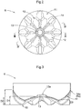
- is a bottom view of a bottom portion of the aseptic filling bottle,
- Fig. 3
- shows a III-III section in
Fig. 2 , and - Fig. 4
- shows a IV-IV section in
Fig. 2 . - Embodiments of an aseptic filling bottle relating to the present invention will be explained with reference to the drawings. An aseptic filling bottle 1 relating to this embodiment includes a spout (mouth) portion 2, a
shoulder portion 4, abody portion 5 and abottom portion 6. Thebottom portion 6 includes agrounding portion 10 that comes into contact with a surface on which the bottle is put, acentral portion 12 that progressively projects to the inner side of the bottle main body as it extends from thegrounding portion 10 to the center of thebottom portion 6, adome portion 13 that projects more to the bottle inner side than thecentral portion 12, and a recededgroove portion 14 that extends radially from thedome portion 13. Thecentral portion 12 is configured such that a bottle inner side projection height D1 of thiscentral portion 12 at a dome portion sidecircumferential edge 12a thereof is set greater than a half D2 of a height measured from thegrounding portion 10 to the border between thebody portion 5 and thebottom portion 6. Moreover, the recededgroove portion 14, at a position corresponding to the radial center position of thegrounding portion 10, has a depth D3 ranging from 5.0 mm to 10.0 mm. With these arrangements, buckling of the bottom portion at the time of refrigerated storage can be effectively suppressed. Next, the aseptic filling bottle relating to this embodiment will be explained in details. - The aseptic filling bottle 1 relating to this embodiment (to be referred to simply as "bottle 1" hereinafter), as shown in
Fig. 1 , includes the spout portion 2 as a spout or a mouse for dispensing liquid and a bottlemain body portion 3 to be filled with the liquid. The bottlemain body portion 3 includes theshoulder portion 4, thebody portion 5 and thebottom portion 6. Theshoulder portion 4 is a portion whose diameter increases progressively toward a bottom face direction continuous with the spout portion 2 and has a shape formed of combination of polygonal panels of various shapes. Thebody portion 5 is a cylindrical portion continuous with theshoulder portion 4. Thebottom portion 6 is a portion in the bottlemain body portion 3, where the circumferential face of the bottlemain body portion 3 has its diameter progressively decreasing toward the bottom face. Namely, in the instant embodiment, the position of the border between thebody portion 5 and thebottom portion 6 is a position in the height direction where the diameter of the bottlemain body portion 3 begins to decrease toward the bottom face. - Here, the bottle 1 relating to the instant embodiment is a bottle for use in an aseptic (germfree) filling method for filling liquid inside a bottle under an aseptic condition. The aseptic filling method allows avoiding exposure of a plastic bottle to a high temperature. So, the heat resistance performance of the bottle 1 can be low and this bottle is formed as a thin and lightweight bottle. The bottle 1 can be molded integrally, e.g. by the biaxial stretch blow molding method with using a thermoplastic resin such as polyethylene, polypropylene, polyethylene terephthalate, etc. as a principal material.
- The bottle 1 relating to this embodiment, as will be described below, is configured to withstand filled contents expansion when the filled (charged) liquid is frozen. Thus, as contents to be filled in the bottle 1, e.g. non-carbonated beverage such as mineral water, tea, soft drink, or juice, which may be stored under a refrigerated state are particularly preferred. However, the bottle may be used suitably also with a carbonated drink (beverage) or a food article such as sauce.
- The
body portion 5 is of a straight body type and in thisbody portion 5, there are formed a plurality of recededribs 7 that extend around its circumferential face. Each recededrib 7 has a shape receded or concave to the inner side in the radial direction (the direction toward a center axis X of the bottle 1 and along its horizontal direction) and the width and the depth of each recededrib 7 are formed approximately constant over the entire circumference. These recededribs 7 function not only as reinforcing ribs for reinforcing the lateral face strength of the bottle 1, but also as portions extendible in the vertical upper direction of the bottle 1 for absorbing possible volumetric expansion of the contents liquid at the time of refrigerated storage. - Incidentally, as such receded
ribs 7, it will suffice to provide at least one at any position of thebody portion 5. Preferably, two or moresuch ribs 7 will be formed in thebody portion 5. More preferably, at least one will be formed at a lower part of the body portion and a plurality will be formed at an upper part of the body portion. Incidentally, if at least one is formed at the body portion lower part and the body portion upper part respectively, this will allow smooth and easy extension in the vertical upper direction of the bottle 1 for absorbing the volumetric expansion of the contents liquid at the time of refrigerated storage. So, the bottle 1 can stand straight on its own without tilting and also no deformation or break of the bottle will occur, either. Further, as shown inFig. 1 , advantageously, the recededrib 7 may be formed to be receded/concave to the radially inner side and along the entire circumference. - As shown in
Figs. 1 through 4 , thebottom portion 6 has anannular grounding portion 10 to be placed on (in contact with) a surface on which the bottle is put such as a desk surface and includes also acircumferential edge portion 11 which is a portion on the radially outer side of the groundingportion 10, acentral portion 12 that is a radially inner side portion relative to the groundingportion 10 and adome portion 13 that is provided at thecentral portion 12 and that projects to more bottle inner side than thecentral portion 12. Thecentral portion 12 has such a shape that projects to the inner side (the upper side inFig. 1 ) of the bottle 1 as it extends to radially inner side from the groundingportion 10 and is formed arcuate from the groundingportion 10 to thedome portion 13. Further, as shown inFig. 3 , thecentral portion 12 is configured such that the bottle inner side projection height D1 of thiscentral portion 12 at the dome portion sidecircumferential edge 12a thereof is set greater than the half D2 of the height measured from the groundingportion 10 to the border 6a between thebody portion 5 and thebottom portion 6. Moreover, thedome portion 13 is provided in a trapezoidal shape as seen in its vertical section. - In the
bottom portion 6, there are formed a plurality (eight in this embodiment) of the recededgroove portions 14 extending from thedome portion 13 to thecircumferential edge portion 11 equidistantly in a radial pattern. With these recededgroove portions 14, the strength of thebottom portion 6 is increased. With the provision of these recededgroove portions 14, thecircumferential edge portion 11 and thecentral portion 12 are divided into a plurality (eight in the present embodiment) in the circumferential direction (the direction around the center axis X of the bottle 1). As shown inFig. 4 , anend portion 14a of each recededgroove portion 14 on the side of thecircumferential edge portion 11 extends to the border 6a between thebody portion 5 and thebottom portion 6. Further, preferably, the recededgroove portion 14 is configured such that the recededgroove portion 14, at a position corresponding to the radial center position of the groundingportion 10, has the depth D3 ranging from 5.0 mm to 10.0 mm (6.6 mm in this embodiment). If it exceeds 10.0 mm, the depth will be excessive to invite impairment of the outer appearance of the bottle 1 or to invite need for design change of some other portion. - As described above, in the bottle 1, the arrangement of not only forming the
dome portion 13 at the center of thebottom portion 6, but also configuring the entirecentral portion 12 from thedome portion 13 to the groundingportion 10 to project to the bottle inner side as extending to the radially inner side, the arrangement of setting the projection height at the dome portion sidecircumferential edge 13a greater than the half of the height of thebottom portion 6, and the arrangement of forming arcuate from the groundingportion 10 to the dome portion sidecircumferential edge 13a together serve to effectively increase the strength of thebottom portion 6. Moreover, the strength of thebottom portion 6 is further increased by the recededgroove portions 14 that extend from thedome portion 13 to thecircumferential edge portion 11. With this, there is ensured strength sufficient to effectively suppress buckling of thebottom portion 6 due to volumetric expansion of the contents at time of refrigerated storage. - Table 1 below shows comparison of three-times tests of a conventional bottle and the bottle 1 relating to the present embodiment. As shown, with the conventional bottle, unlike the bottle 1 relating to the present embodiment, the depth of the portion corresponding to the depth D3 shown in
Fig. 3 (the depth at the position of the recededgroove portion 14 corresponding to the radial center of the grounding portion 10) is below 5 mm.[Table 1] Embodiment Conventional filling amount (ml) 650 490 N=1 Pass Pass N=2 Pass Failure N=3 Pass Failure - Pass:
- The bottle stands stably after refrigeration.
- Failure:
- The bottle does not stand stably after refrigeration.
- As can be seen from Table 1, the bottle 1 relating to the present embodiment is more stable in the case of the large-volume bottle having a filling amount of 650 ml, this means the suppression of buckling of the
bottom portion 6. In this way, it may be understood that with the bottle 1 relating to the present embodiment, strength sufficient to suppress the buckling of thebottom portion 6 due to volumetric expansion of the contents at time of refrigerated storage (and also heated storage) is ensured. - Lastly, other embodiments of the aseptic filling bottle relating to the present invention will be explained. Incidentally, the arrangements/configurations disclosed in the respective following embodiments can be used in any combination with the arrangements/configurations disclosed in the other embodiments unless no contradiction occurs resulting therefrom.
- (1) In the foregoing embodiment, there was explained an example in which the
body portion 5 is configured as a straight body type. However, the present invention is not limited thereto. For instance, thebody portion 5 may be provided with a constricted portion, in addition to the straight body portion. - (2) In the foregoing embodiment, between the respective receded
groove portions 14, a receded small groove portion smaller than the recededgroove portion 14 may be provided additionally from the groundingportion 10 to thecircumferential edge portion 11. With this, the strength of the bottom portion can be further increased. - (3) Further, regarding the other arrangements/configurations too, it is understood that the embodiments disclosed in this detailed disclosure are only illustrative in all respects thereof, and the scope of the present invention is not limited thereto. One skilled in the art could easily understand that appropriate modifications will be possible within the scope not departing from the spirit of the invention. Therefore, it is as a matter of course that other embodiments with such modifications not departing form the spirit of the invention are also included in the scope of the present invention.
- The present invention is applicable to e.g. a plastic bottle filled with contents liquid by an aseptic filling method.
-
- 1: aseptic filling bottle
- 2: spout portion
- 4: shoulder portion
- 5: body portion
- 6: bottom portion
- 7: receded rib
- 10: grounding portion
- 11: circumferential edge
- 12: central portion
- 13: dome portion
- 14: receded groove portion
- D1: projection height of central portion at dome portion side circumferential edge to bottle inner side
- D2: a half of height from grounding portion to border between body portion and bottom portion
- D3: height at position in receded groove portion corresponding to radial center of grounding portion
Claims (4)
- An aseptic filling bottle including a spout portion, a shoulder portion, a body portion and a bottom portion;
wherein the bottom portion includes a grounding portion to be placed in contact with a surface on which the bottle is put, a central portion that projects to an inner side of the bottle as its extends radially inwards from the grounding portion, a dome portion which projects to more inner side of the bottle than the central portion, and a receded groove portion that extends radially from the dome portion;
wherein a bottom inner side projection height of the central portion at a dome portion side circumferential edge thereof is set greater than a half of a height from the grounding portion to a border between the body portion and the bottom portion; and
wherein the receded groove portion, at a position corresponding to the radial center position of the grounding portion, has a depth ranging from 5.0 mm to 10.0 mm. - The aseptic filling bottle of claim 1, wherein the central portion is formed arcuate.
- The aseptic filling bottle of claim 1 or 2, wherein the receded groove portion extends from the dome portion to a circumferential edge on more radial outer side than the grounding portion.
- The aseptic filling bottle of any one of claims 1-3, wherein
in the body portion, there is formed at least one receded rib which extends around a circumferential face of the body portion.
Applications Claiming Priority (2)
| Application Number | Priority Date | Filing Date | Title |
|---|---|---|---|
| JP2017043159A JP7241456B2 (en) | 2017-03-07 | 2017-03-07 | aseptic filling bottle |
| PCT/JP2018/008551 WO2018164111A1 (en) | 2017-03-07 | 2018-03-06 | Aseptic filling bottle |
Publications (3)
| Publication Number | Publication Date |
|---|---|
| EP3594142A1 true EP3594142A1 (en) | 2020-01-15 |
| EP3594142A4 EP3594142A4 (en) | 2021-01-27 |
| EP3594142B1 EP3594142B1 (en) | 2025-12-24 |
Family
ID=63447604
Family Applications (1)
| Application Number | Title | Priority Date | Filing Date |
|---|---|---|---|
| EP18763036.3A Active EP3594142B1 (en) | 2017-03-07 | 2018-03-06 | Aseptic filling bottle |
Country Status (7)
| Country | Link |
|---|---|
| US (1) | US20200055629A1 (en) |
| EP (1) | EP3594142B1 (en) |
| JP (1) | JP7241456B2 (en) |
| CN (1) | CN110461719B (en) |
| AU (1) | AU2018232270B2 (en) |
| ES (1) | ES3058706T3 (en) |
| WO (1) | WO2018164111A1 (en) |
Families Citing this family (3)
| Publication number | Priority date | Publication date | Assignee | Title |
|---|---|---|---|---|
| JP7454914B2 (en) * | 2019-03-29 | 2024-03-25 | サントリーホールディングス株式会社 | plastic bottle |
| FR3163060B1 (en) * | 2024-06-06 | 2026-06-05 | Sidel Participations | Container having a corrugated base and mold base for manufacturing such a container |
| USD1126002S1 (en) | 2024-10-08 | 2026-05-12 | Co2Pac Limited | Container |
Family Cites Families (11)
| Publication number | Priority date | Publication date | Assignee | Title |
|---|---|---|---|---|
| JP3818842B2 (en) * | 2000-10-10 | 2006-09-06 | 花王株式会社 | Direct blow molded container |
| FR2910438B1 (en) * | 2006-12-21 | 2010-12-10 | Evian Saeme Sa | CHAMPAGNE BOTTLE PLASTIC BOTTLE AND MANUFACTURING METHOD THEREOF |
| FR2932458B1 (en) * | 2008-06-13 | 2010-08-20 | Sidel Participations | CONTAINER, IN PARTICULAR BOTTLE, IN THERMOPLASTIC MATERIAL EQUIPPED WITH A REINFORCED BACKGROUND |
| JP5221502B2 (en) * | 2009-12-07 | 2013-06-26 | 麒麟麦酒株式会社 | Plastic container for beverage and beverage product using the same |
| JP6035701B2 (en) * | 2010-12-28 | 2016-11-30 | 大日本印刷株式会社 | Plastic bottle |
| WO2012029665A1 (en) * | 2010-09-01 | 2012-03-08 | 大日本印刷株式会社 | Plastic bottle |
| DE102013101332A1 (en) * | 2013-02-11 | 2014-08-14 | Krones Ag | Plastic container |
| FR3005035B1 (en) * | 2013-04-24 | 2016-01-15 | Sidel Participations | CONTAINER PROVIDED WITH A DOUBLE ARCHE DEFORMABLE BOTTOM |
| FR3007392B1 (en) * | 2013-06-25 | 2016-02-05 | Sidel Participations | RECIPIENT MINI PETALOIDE GROOVE |
| JP6326386B2 (en) * | 2014-12-03 | 2018-05-16 | 石塚硝子株式会社 | Resin packaging container bottom structure |
| JP7012417B2 (en) * | 2015-05-20 | 2022-01-28 | サントリーホールディングス株式会社 | Aseptic filling bottle |
-
2017
- 2017-03-07 JP JP2017043159A patent/JP7241456B2/en active Active
-
2018
- 2018-03-06 ES ES18763036T patent/ES3058706T3/en active Active
- 2018-03-06 AU AU2018232270A patent/AU2018232270B2/en active Active
- 2018-03-06 WO PCT/JP2018/008551 patent/WO2018164111A1/en not_active Ceased
- 2018-03-06 US US16/486,213 patent/US20200055629A1/en not_active Abandoned
- 2018-03-06 CN CN201880016562.1A patent/CN110461719B/en active Active
- 2018-03-06 EP EP18763036.3A patent/EP3594142B1/en active Active
Also Published As
| Publication number | Publication date |
|---|---|
| WO2018164111A1 (en) | 2018-09-13 |
| AU2018232270B2 (en) | 2023-05-25 |
| EP3594142A4 (en) | 2021-01-27 |
| ES3058706T3 (en) | 2026-03-12 |
| AU2018232270A1 (en) | 2019-08-29 |
| JP7241456B2 (en) | 2023-03-17 |
| US20200055629A1 (en) | 2020-02-20 |
| CN110461719A (en) | 2019-11-15 |
| JP2018144862A (en) | 2018-09-20 |
| CN110461719B (en) | 2021-06-22 |
| EP3594142B1 (en) | 2025-12-24 |
Similar Documents
| Publication | Publication Date | Title |
|---|---|---|
| EP3299306B1 (en) | Bottle for aseptic packing | |
| US8910812B2 (en) | Container with grip panel and annular rib having variable width | |
| US20160167825A1 (en) | Plastic container and blow mould for the production thereof | |
| US8991628B2 (en) | Hot-fill jar base | |
| US10358250B2 (en) | Plastics material container | |
| US20080179271A1 (en) | Nitrogen dosed base | |
| EP3594142B1 (en) | Aseptic filling bottle | |
| EP3290345B1 (en) | Synthetic resin container | |
| JP2009154963A (en) | Resin container | |
| US20090134117A1 (en) | Container Having Vacuum Compensation Elements | |
| JP2009255926A (en) | Synthetic resin container | |
| US12006122B2 (en) | Synthetic resin bottle | |
| US11352184B2 (en) | Container | |
| EP3275801B1 (en) | Lid assembly for resin container | |
| JP2010105677A (en) | Resin container with buckling resistance and beverage product using the same | |
| JP2016216094A (en) | Aseptic filling bottle and filling bottle | |
| US11161667B2 (en) | Plastic container with pivotable base portion | |
| US20210155361A1 (en) | Container for receiving liquids | |
| JP2000238736A (en) | Plastic container | |
| JP2022171110A (en) | Container made of synthetic resin | |
| AU2018324628A1 (en) | Plastic bottle | |
| JP2007119010A (en) | Synthetic resin bottle-type container with a vacuum absorbing panel |
Legal Events
| Date | Code | Title | Description |
|---|---|---|---|
| STAA | Information on the status of an ep patent application or granted ep patent |
Free format text: STATUS: THE INTERNATIONAL PUBLICATION HAS BEEN MADE |
|
| PUAI | Public reference made under article 153(3) epc to a published international application that has entered the european phase |
Free format text: ORIGINAL CODE: 0009012 |
|
| STAA | Information on the status of an ep patent application or granted ep patent |
Free format text: STATUS: REQUEST FOR EXAMINATION WAS MADE |
|
| 17P | Request for examination filed |
Effective date: 20190921 |
|
| AK | Designated contracting states |
Kind code of ref document: A1 Designated state(s): AL AT BE BG CH CY CZ DE DK EE ES FI FR GB GR HR HU IE IS IT LI LT LU LV MC MK MT NL NO PL PT RO RS SE SI SK SM TR |
|
| AX | Request for extension of the european patent |
Extension state: BA ME |
|
| DAV | Request for validation of the european patent (deleted) | ||
| DAX | Request for extension of the european patent (deleted) | ||
| A4 | Supplementary search report drawn up and despatched |
Effective date: 20210112 |
|
| RIC1 | Information provided on ipc code assigned before grant |
Ipc: B65D 1/02 20060101AFI20201221BHEP |
|
| STAA | Information on the status of an ep patent application or granted ep patent |
Free format text: STATUS: EXAMINATION IS IN PROGRESS |
|
| 17Q | First examination report despatched |
Effective date: 20221021 |
|
| GRAP | Despatch of communication of intention to grant a patent |
Free format text: ORIGINAL CODE: EPIDOSNIGR1 |
|
| STAA | Information on the status of an ep patent application or granted ep patent |
Free format text: STATUS: GRANT OF PATENT IS INTENDED |
|
| INTG | Intention to grant announced |
Effective date: 20250922 |
|
| GRAS | Grant fee paid |
Free format text: ORIGINAL CODE: EPIDOSNIGR3 |
|
| GRAA | (expected) grant |
Free format text: ORIGINAL CODE: 0009210 |
|
| STAA | Information on the status of an ep patent application or granted ep patent |
Free format text: STATUS: THE PATENT HAS BEEN GRANTED |
|
| AK | Designated contracting states |
Kind code of ref document: B1 Designated state(s): AL AT BE BG CH CY CZ DE DK EE ES FI FR GB GR HR HU IE IS IT LI LT LU LV MC MK MT NL NO PL PT RO RS SE SI SK SM TR |
|
| P01 | Opt-out of the competence of the unified patent court (upc) registered |
Free format text: CASE NUMBER: UPC_APP_0013182_3594142/2025 Effective date: 20251113 |
|
| REG | Reference to a national code |
Ref country code: CH Ref legal event code: F10 Free format text: ST27 STATUS EVENT CODE: U-0-0-F10-F00 (AS PROVIDED BY THE NATIONAL OFFICE) Effective date: 20251224 Ref country code: GB Ref legal event code: FG4D |
|
| REG | Reference to a national code |
Ref country code: DE Ref legal event code: R096 Ref document number: 602018088134 Country of ref document: DE |
|
| REG | Reference to a national code |
Ref country code: ES Ref legal event code: FG2A Ref document number: 3058706 Country of ref document: ES Kind code of ref document: T3 Effective date: 20260312 |
|
| PGFP | Annual fee paid to national office [announced via postgrant information from national office to epo] |
Ref country code: GB Payment date: 20260311 Year of fee payment: 9 |
|
| REG | Reference to a national code |
Ref country code: LT Ref legal event code: MG9D |
|
| PG25 | Lapsed in a contracting state [announced via postgrant information from national office to epo] |
Ref country code: NO Free format text: LAPSE BECAUSE OF FAILURE TO SUBMIT A TRANSLATION OF THE DESCRIPTION OR TO PAY THE FEE WITHIN THE PRESCRIBED TIME-LIMIT Effective date: 20260324 |
|
| PGFP | Annual fee paid to national office [announced via postgrant information from national office to epo] |
Ref country code: DE Payment date: 20260327 Year of fee payment: 9 |
|
| PG25 | Lapsed in a contracting state [announced via postgrant information from national office to epo] |
Ref country code: HR Free format text: LAPSE BECAUSE OF FAILURE TO SUBMIT A TRANSLATION OF THE DESCRIPTION OR TO PAY THE FEE WITHIN THE PRESCRIBED TIME-LIMIT Effective date: 20251224 Ref country code: FI Free format text: LAPSE BECAUSE OF FAILURE TO SUBMIT A TRANSLATION OF THE DESCRIPTION OR TO PAY THE FEE WITHIN THE PRESCRIBED TIME-LIMIT Effective date: 20251224 |
|
| PG25 | Lapsed in a contracting state [announced via postgrant information from national office to epo] |
Ref country code: RS Free format text: LAPSE BECAUSE OF FAILURE TO SUBMIT A TRANSLATION OF THE DESCRIPTION OR TO PAY THE FEE WITHIN THE PRESCRIBED TIME-LIMIT Effective date: 20260324 |
|
| PGFP | Annual fee paid to national office [announced via postgrant information from national office to epo] |
Ref country code: FR Payment date: 20260323 Year of fee payment: 9 |
|
| PG25 | Lapsed in a contracting state [announced via postgrant information from national office to epo] |
Ref country code: LV Free format text: LAPSE BECAUSE OF FAILURE TO SUBMIT A TRANSLATION OF THE DESCRIPTION OR TO PAY THE FEE WITHIN THE PRESCRIBED TIME-LIMIT Effective date: 20251224 |
|
| REG | Reference to a national code |
Ref country code: NL Ref legal event code: MP Effective date: 20251224 |
|
| PG25 | Lapsed in a contracting state [announced via postgrant information from national office to epo] |
Ref country code: BG Free format text: LAPSE BECAUSE OF FAILURE TO SUBMIT A TRANSLATION OF THE DESCRIPTION OR TO PAY THE FEE WITHIN THE PRESCRIBED TIME-LIMIT Effective date: 20251224 |
|
| REG | Reference to a national code |
Ref country code: AT Ref legal event code: MK05 Ref document number: 1870593 Country of ref document: AT Kind code of ref document: T Effective date: 20251224 |
|
| PG25 | Lapsed in a contracting state [announced via postgrant information from national office to epo] |
Ref country code: NL Free format text: LAPSE BECAUSE OF FAILURE TO SUBMIT A TRANSLATION OF THE DESCRIPTION OR TO PAY THE FEE WITHIN THE PRESCRIBED TIME-LIMIT Effective date: 20251224 |
|
| PG25 | Lapsed in a contracting state [announced via postgrant information from national office to epo] |
Ref country code: LT Free format text: LAPSE BECAUSE OF FAILURE TO SUBMIT A TRANSLATION OF THE DESCRIPTION OR TO PAY THE FEE WITHIN THE PRESCRIBED TIME-LIMIT Effective date: 20251224 |
|
| PG25 | Lapsed in a contracting state [announced via postgrant information from national office to epo] |
Ref country code: SM Free format text: LAPSE BECAUSE OF FAILURE TO SUBMIT A TRANSLATION OF THE DESCRIPTION OR TO PAY THE FEE WITHIN THE PRESCRIBED TIME-LIMIT Effective date: 20251224 |
|
| PGFP | Annual fee paid to national office [announced via postgrant information from national office to epo] |
Ref country code: ES Payment date: 20260414 Year of fee payment: 9 |
|
| PG25 | Lapsed in a contracting state [announced via postgrant information from national office to epo] |
Ref country code: PL Free format text: LAPSE BECAUSE OF FAILURE TO SUBMIT A TRANSLATION OF THE DESCRIPTION OR TO PAY THE FEE WITHIN THE PRESCRIBED TIME-LIMIT Effective date: 20251224 |
|
| PG25 | Lapsed in a contracting state [announced via postgrant information from national office to epo] |
Ref country code: IT Free format text: LAPSE BECAUSE OF FAILURE TO SUBMIT A TRANSLATION OF THE DESCRIPTION OR TO PAY THE FEE WITHIN THE PRESCRIBED TIME-LIMIT Effective date: 20251224 |
|
| PG25 | Lapsed in a contracting state [announced via postgrant information from national office to epo] |
Ref country code: AT Free format text: LAPSE BECAUSE OF FAILURE TO SUBMIT A TRANSLATION OF THE DESCRIPTION OR TO PAY THE FEE WITHIN THE PRESCRIBED TIME-LIMIT Effective date: 20251224 |
|
| PG25 | Lapsed in a contracting state [announced via postgrant information from national office to epo] |
Ref country code: EE Free format text: LAPSE BECAUSE OF FAILURE TO SUBMIT A TRANSLATION OF THE DESCRIPTION OR TO PAY THE FEE WITHIN THE PRESCRIBED TIME-LIMIT Effective date: 20251224 |
|
| PG25 | Lapsed in a contracting state [announced via postgrant information from national office to epo] |
Ref country code: PT Free format text: LAPSE BECAUSE OF FAILURE TO SUBMIT A TRANSLATION OF THE DESCRIPTION OR TO PAY THE FEE WITHIN THE PRESCRIBED TIME-LIMIT Effective date: 20260424 Ref country code: IS Free format text: LAPSE BECAUSE OF FAILURE TO SUBMIT A TRANSLATION OF THE DESCRIPTION OR TO PAY THE FEE WITHIN THE PRESCRIBED TIME-LIMIT Effective date: 20260424 |
|
| PG25 | Lapsed in a contracting state [announced via postgrant information from national office to epo] |
Ref country code: CZ Free format text: LAPSE BECAUSE OF FAILURE TO SUBMIT A TRANSLATION OF THE DESCRIPTION OR TO PAY THE FEE WITHIN THE PRESCRIBED TIME-LIMIT Effective date: 20251224 |
|
| PG25 | Lapsed in a contracting state [announced via postgrant information from national office to epo] |
Ref country code: SK Free format text: LAPSE BECAUSE OF FAILURE TO SUBMIT A TRANSLATION OF THE DESCRIPTION OR TO PAY THE FEE WITHIN THE PRESCRIBED TIME-LIMIT Effective date: 20251224 |
|
| PG25 | Lapsed in a contracting state [announced via postgrant information from national office to epo] |
Ref country code: SE Free format text: LAPSE BECAUSE OF FAILURE TO SUBMIT A TRANSLATION OF THE DESCRIPTION OR TO PAY THE FEE WITHIN THE PRESCRIBED TIME-LIMIT Effective date: 20251224 |