EP3594075A1 - Compact gearbox design for windshield wiper system - Google Patents
Compact gearbox design for windshield wiper system Download PDFInfo
- Publication number
- EP3594075A1 EP3594075A1 EP19186155.8A EP19186155A EP3594075A1 EP 3594075 A1 EP3594075 A1 EP 3594075A1 EP 19186155 A EP19186155 A EP 19186155A EP 3594075 A1 EP3594075 A1 EP 3594075A1
- Authority
- EP
- European Patent Office
- Prior art keywords
- gear
- wws
- output shaft
- internally
- sector gear
- Prior art date
- Legal status (The legal status is an assumption and is not a legal conclusion. Google has not performed a legal analysis and makes no representation as to the accuracy of the status listed.)
- Granted
Links
Images


Classifications
-
- B—PERFORMING OPERATIONS; TRANSPORTING
- B60—VEHICLES IN GENERAL
- B60S—SERVICING, CLEANING, REPAIRING, SUPPORTING, LIFTING, OR MANOEUVRING OF VEHICLES, NOT OTHERWISE PROVIDED FOR
- B60S1/00—Cleaning of vehicles
- B60S1/02—Cleaning windscreens, windows or optical devices
- B60S1/04—Wipers or the like, e.g. scrapers
- B60S1/06—Wipers or the like, e.g. scrapers characterised by the drive
- B60S1/16—Means for transmitting drive
- B60S1/18—Means for transmitting drive mechanically
- B60S1/185—Means for transmitting drive mechanically with means for stopping or setting the wipers at their limit of movement
-
- B—PERFORMING OPERATIONS; TRANSPORTING
- B60—VEHICLES IN GENERAL
- B60S—SERVICING, CLEANING, REPAIRING, SUPPORTING, LIFTING, OR MANOEUVRING OF VEHICLES, NOT OTHERWISE PROVIDED FOR
- B60S1/00—Cleaning of vehicles
- B60S1/02—Cleaning windscreens, windows or optical devices
- B60S1/04—Wipers or the like, e.g. scrapers
- B60S1/06—Wipers or the like, e.g. scrapers characterised by the drive
- B60S1/08—Wipers or the like, e.g. scrapers characterised by the drive electrically driven
-
- B—PERFORMING OPERATIONS; TRANSPORTING
- B60—VEHICLES IN GENERAL
- B60S—SERVICING, CLEANING, REPAIRING, SUPPORTING, LIFTING, OR MANOEUVRING OF VEHICLES, NOT OTHERWISE PROVIDED FOR
- B60S1/00—Cleaning of vehicles
- B60S1/02—Cleaning windscreens, windows or optical devices
- B60S1/04—Wipers or the like, e.g. scrapers
- B60S1/06—Wipers or the like, e.g. scrapers characterised by the drive
- B60S1/16—Means for transmitting drive
-
- B—PERFORMING OPERATIONS; TRANSPORTING
- B60—VEHICLES IN GENERAL
- B60S—SERVICING, CLEANING, REPAIRING, SUPPORTING, LIFTING, OR MANOEUVRING OF VEHICLES, NOT OTHERWISE PROVIDED FOR
- B60S1/00—Cleaning of vehicles
- B60S1/02—Cleaning windscreens, windows or optical devices
- B60S1/04—Wipers or the like, e.g. scrapers
- B60S1/06—Wipers or the like, e.g. scrapers characterised by the drive
- B60S1/16—Means for transmitting drive
- B60S1/166—Means for transmitting drive characterised by the combination of a motor-reduction unit and a mechanism for converting rotary into oscillatory movement
-
- B—PERFORMING OPERATIONS; TRANSPORTING
- B60—VEHICLES IN GENERAL
- B60S—SERVICING, CLEANING, REPAIRING, SUPPORTING, LIFTING, OR MANOEUVRING OF VEHICLES, NOT OTHERWISE PROVIDED FOR
- B60S1/00—Cleaning of vehicles
- B60S1/02—Cleaning windscreens, windows or optical devices
- B60S1/04—Wipers or the like, e.g. scrapers
- B60S1/06—Wipers or the like, e.g. scrapers characterised by the drive
- B60S1/16—Means for transmitting drive
- B60S1/18—Means for transmitting drive mechanically
- B60S1/26—Means for transmitting drive mechanically by toothed gearing
-
- F—MECHANICAL ENGINEERING; LIGHTING; HEATING; WEAPONS; BLASTING
- F16—ENGINEERING ELEMENTS AND UNITS; GENERAL MEASURES FOR PRODUCING AND MAINTAINING EFFECTIVE FUNCTIONING OF MACHINES OR INSTALLATIONS; THERMAL INSULATION IN GENERAL
- F16H—GEARING
- F16H19/00—Gearings comprising essentially only toothed gears or friction members and not capable of conveying indefinitely-continuing rotary motion
- F16H19/001—Gearings comprising essentially only toothed gears or friction members and not capable of conveying indefinitely-continuing rotary motion for conveying reciprocating or limited rotary motion
Definitions
- the following description relates to a windshield wiper system (WWS) of an aircraft and, more specifically, to a WWS of an aircraft with a compact gearbox design powered by a bi-directional brushless direct current (BLDC) motor.
- WWS windshield wiper system
- BLDC brushless direct current
- a WWS of an aircraft is used for cleaning rain, sand, dust, etc. from a windshield.
- a WWS includes a wiper arm that needs to move in both clockwise and counter-clockwise directions within a specific angle to keep the windshield clean for the pilot/co-pilot to have good visibility.
- the wiper arm is typically moved by a shaft that is connected to a motor through gearing but there are various design configurations available and each has its own advantages and disadvantages.
- a WWS of an aircraft is operated as follows. Initially, pilot or co-pilot input activates an electronic control unit (ECU) and the ECU controls a BLDC motor accordingly.
- the ECU periodically reverses the BLDC motor direction to achieve oscillatory motion at the output shaft of the BLDC motor.
- the BLDC motor output shaft interfaces with a two-stage gear train to achieve required torque and speed at the gearbox output shaft. This oscillatory motion at the gearbox output shaft is transferred to the wiper externals.
- a windshield wiper system includes a brushless direct current (BLDC) motor with a motor output shaft gear, a gear train and an internally cut sector gear.
- the gear train includes a first gear, which has a first diameter and engages with the motor output shaft gear, and a second gear, which has a second diameter that is shorter than the first diameter and rotates with the first gear.
- the internally cut sector gear is coupled with an output shaft and formed to define an internal geared groove that engages with the second gear.
- an arc-length of the internal geared groove exceeds a required sweep angle of the WWS.
- the internally cut sector gear includes stoppers at opposite ends of the internal geared groove.
- a controller stores overcurrent trip logic.
- mechanical interference between the second gear and either opposite end of the internal geared groove activates the overcurrent trip logic of the controller.
- an axis of the output shaft is proximate to an exterior diameter of the first gear.
- the internally cut sector gear includes a hub portion from which the output shaft extends and a sector gear portion, which extends radially outwardly from the hub portion and in which the internal geared groove is defined.
- the sector gear portion includes an internal diameter portion comprising a smooth exterior facing surface, first and second radial portions extending radially outwardly from the internal diameter portion and apart from each other and an exterior diameter portion comprising internally facing teeth.
- first and second radial portions respectively include smooth internally facing surfaces and stoppers disposed along the smooth internally facing surfaces.
- an internally cut sector gear of a windshield wiper system includes a hub portion from which an output shaft extends toward wipers of the WWS and a sector gear portion, which extends radially outwardly from the hub portion and in which an internal geared groove is defined for engagement with a motor driven gear train.
- an arc-length of the internal geared groove exceeds a required sweep angle of the WWS.
- the internally cut sector gear includes stoppers at opposite ends of the internal geared groove.
- an axis of the output shaft is proximate to an exterior diameter of a large diameter gear of the gear train.
- the sector gear portion includes an internal diameter portion comprising a smooth exterior facing surface, first and second radial portions extending radially outwardly from the internal diameter portion and apart from each other and an exterior diameter portion comprising internally facing teeth.
- first and second radial portions respectively include smooth internally facing surfaces and stoppers disposed along the smooth internally facing surfaces.
- a method of operating a windshield wiper system includes driving a brushless direct current (BLDC) motor with an output shaft gear in a first direction with the output shaft gear engaged with a gear train that is, in turn, engaged with an internal geared grooved of an internally cut sector gear that is coupled with an output shaft, sensing an overcurrent condition arising from the gear train engaging with an end of the internal geared groove and stopping the driving of the BLDC motor in the first direction.
- BLDC brushless direct current
- the method further includes driving the BLDC motor in a second direction opposite the first direction, sensing an overcurrent condition arising from the gear train engaging with an opposite end of the internal geared groove, stopping the driving of the BLDC motor in the second direction and repeating the driving of the BLDC motor in the first direction.
- the driving includes determining when the gear train is close to engagement with the end of the internal groove, driving the BLDC motor in a second direction opposite the first direction, determining when the gear train is close to engagement with an opposite end of the internal groove and repeating the driving the BLDC motor in the first direction.
- an arc-length of the internal geared groove exceeds a required sweep angle of the WWS.
- logic for executing the sensing and the stopping is provided in a controller of the BLDC motor.
- a windshield wiper system is provided to have a compact gearbox design with hard mechanical stops.
- the compact gearbox design includes an internally cut sector gear that is formed to define an internal geared groove. Opposite ends of the internal geared groove provide for mechanical stops and the internalization of the internal geared groove reduces an overall envelop of the gearbox design.
- a windshield wiper system (WWS) 10 is provided and includes a brushless direct current (BLDC) motor 20 that is operable in opposite first and second directions and includes a rotatable shaft 21 with a motor output shaft gear 22, a gear train 30 and an internally cut sector gear 40.
- the gear train 30 includes a first gear 31 and a second gear 32.
- the first gear 31 has a first diameter D1 (see FIG. 2 ) and engages with the motor output shaft gear 22.
- the second gear 32 has a second diameter D2 that is shorter than the first diameter D1 and rotates about a rotational axis that is common to the first gear 31 and the second gear 32.
- the second gear 32 rotates with the first gear 31.
- the internally cut sector gear 40 is coupled with an output shaft 50 that connects with wiper blades of the WWS 10.
- the internally cut sector gear 40 is formed to define an internal geared groove 41 that engages with the second gear 32.
- the gear train 30 may be configured such that an input speed of the motor output shaft gear 22 is decreased by the gear ratio between the first gear 31 and the second gear 32.
- an axis AOS of the output shaft 50 may be proximate to an outer diameter of the first gear 31.
- the axis AOS of the output shaft 50 may be within one diameter of the output shaft 50 from the outer diameter of the first gear 31. This has the effect of decreasing an overall envelope of the WWS 10 as compared to conventional systems in which the output shaft is coupled to a gear with external gearing.
- the motor output shaft gear 22 drives rotations of the first gear 31 and the second gear 32.
- the engagement between the second gear 32 and the internal geared groove 41 causes the internally cut sector gear 40 to rotate about a rotational axis A1.
- the axis AOS of the output shaft 50 may extend along the rotational axis A1.
- the rotation of the internally cut sector gear 40 continues until the second gear 32 reaches an end 410 of the internal geared groove 41.
- the BLDC motor 20 can be stopped by logic of a controller 301 (see FIG. 3 ) to be described below or reversed such that the rotation of the internally cut sector gear 40 reverses direction with the second gear 32 proceeding toward an opposite end 411 of the internal geared groove 41.
- An arc-length of the internal geared groove 41 may exceed or only slightly exceed a required sweep angle of the blades of the WWS 10 (see FIG. 4 ).
- the internal geared groove 41 has the opposite ends 410 and 411 and may include stoppers 42 at the opposite ends 410 and 411.
- the stoppers 42 can provide a hard stop to the second gear 32 to indicate to the controller 301 that the second gear 32 has overreached and thus reached one of the ends 410 and 411 of the internal geared groove 41 and, in some cases, to indicate to the controller 301 in particular that the BLDC motor 20 has been driven to rotate too far in one direction. This indication can lead to overcurrent trip logic being engaged.
- the controller 301 may be provided as an electronic control unit (ECU) that is receptive of pilot or co-pilot input to start the WWS 10 and which is disposed and configured to operate the BLDC motor 20 in the first and second directions.
- the controller 301 includes a processing unit 310, a memory unit 320 and an input/output (I/O) unit 330 by which the processing unit 310 is communicative with the BLDC motor 20.
- the memory unit 320 has executable instructions stored thereon, which are readable and executable by the processing unit 310 to cause the processing unit 310 to operate as described herein.
- the executable instructions of the memory unit 320 define an overcurrent trip logic element that can be activated to being the WWS 10 to a halt when there is an overshoot leading to a locked condition and current being drawn from the BLDC motor 20 increasing.
- the internally cut sector gear 40 includes a hub portion 401, from which the output shaft 50 extends, and a sector gear portion 402.
- the sector gear portion 402 extends radially outwardly from the hub portion 401.
- the internal geared groove 41 is defined within the sector gear portion 402.
- the sector gear portion 402 includes an internal diameter portion 403 that includes a smooth exterior facing surface 404, first and second radial portions 405 and 406 that extend radially outwardly from the internal diameter portion 403 and which taper apart from each other with increasing distance from the hub portion 401 and an exterior diameter portion 407.
- the first and second radial portions 405 and 406 each include a smooth internally facing surface 408 from which a stopper 42 extends inwardly.
- the exterior diameter portion 407 includes internally facing teeth 409 that engage with the second gear 32.
- a method of operating the WWS 10 includes receiving a pilot or co-pilot input to operate the WWS 10 and accordingly driving the BLDC motor 20 in a first direction (501).
- the method further includes sensing a signal of an overcurrent condition arising from the second gear 32 of the gear train 30 engaging with an end 410 of the internal geared groove 41 (502) and stopping the driving of the BLDC motor 20 in the first direction (503).
- the stopping of the driving of the BLDC motor 20 in the first direction of operation 503 can also be executed in response to a determination from readings of proximal position sensors that the second gear 32 of the gear train 30 is close to engagement with the end 410 of the internal geared groove 41.
- the method may further include driving the BLDC motor 20 in a second direction opposite the first direction (504), sensing a signal of an overcurrent condition arising from the second gear 32 of the gear train 30 engaging with an opposite end 411 of the internal geared groove 41 (505), stopping the driving of the BLDC motor 20 in the second direction (506) and repeating the driving of the BLDC motor 20 in the first direction (507).
- the stopping of the driving of the BLDC motor 20 in the second direction of operation 506 can also be executed in response to a new determination from readings of the proximal position sensors that the second gear 32 of the gear train 30 is close to engagement with the end 411 of the internal geared groove 41.
Landscapes
- Engineering & Computer Science (AREA)
- Mechanical Engineering (AREA)
- General Engineering & Computer Science (AREA)
- Connection Of Motors, Electrical Generators, Mechanical Devices, And The Like (AREA)
Abstract
Description
- The following description relates to a windshield wiper system (WWS) of an aircraft and, more specifically, to a WWS of an aircraft with a compact gearbox design powered by a bi-directional brushless direct current (BLDC) motor.
- A WWS of an aircraft is used for cleaning rain, sand, dust, etc. from a windshield. Generally, a WWS includes a wiper arm that needs to move in both clockwise and counter-clockwise directions within a specific angle to keep the windshield clean for the pilot/co-pilot to have good visibility. The wiper arm is typically moved by a shaft that is connected to a motor through gearing but there are various design configurations available and each has its own advantages and disadvantages.
- Typically, a WWS of an aircraft is operated as follows. Initially, pilot or co-pilot input activates an electronic control unit (ECU) and the ECU controls a BLDC motor accordingly. The ECU periodically reverses the BLDC motor direction to achieve oscillatory motion at the output shaft of the BLDC motor. The BLDC motor output shaft interfaces with a two-stage gear train to achieve required torque and speed at the gearbox output shaft. This oscillatory motion at the gearbox output shaft is transferred to the wiper externals.
- According to an aspect of the disclosure, a windshield wiper system (WWS) is provided and includes a brushless direct current (BLDC) motor with a motor output shaft gear, a gear train and an internally cut sector gear. The gear train includes a first gear, which has a first diameter and engages with the motor output shaft gear, and a second gear, which has a second diameter that is shorter than the first diameter and rotates with the first gear. The internally cut sector gear is coupled with an output shaft and formed to define an internal geared groove that engages with the second gear.
- In accordance with additional or alternative embodiments, an arc-length of the internal geared groove exceeds a required sweep angle of the WWS.
- In accordance with additional or alternative embodiments, the internally cut sector gear includes stoppers at opposite ends of the internal geared groove.
- In accordance with additional or alternative embodiments, a controller stores overcurrent trip logic.
- In accordance with additional or alternative embodiments, mechanical interference between the second gear and either opposite end of the internal geared groove activates the overcurrent trip logic of the controller.
- In accordance with additional or alternative embodiments, an axis of the output shaft is proximate to an exterior diameter of the first gear.
- In accordance with additional or alternative embodiments, the internally cut sector gear includes a hub portion from which the output shaft extends and a sector gear portion, which extends radially outwardly from the hub portion and in which the internal geared groove is defined.
- In accordance with additional or alternative embodiments, the sector gear portion includes an internal diameter portion comprising a smooth exterior facing surface, first and second radial portions extending radially outwardly from the internal diameter portion and apart from each other and an exterior diameter portion comprising internally facing teeth.
- In accordance with additional or alternative embodiments, the first and second radial portions respectively include smooth internally facing surfaces and stoppers disposed along the smooth internally facing surfaces.
- According to another aspect of the disclosure, an internally cut sector gear of a windshield wiper system (WWS) is provided and includes a hub portion from which an output shaft extends toward wipers of the WWS and a sector gear portion, which extends radially outwardly from the hub portion and in which an internal geared groove is defined for engagement with a motor driven gear train.
- In accordance with additional or alternative embodiments, an arc-length of the internal geared groove exceeds a required sweep angle of the WWS.
- In accordance with additional or alternative embodiments, the internally cut sector gear includes stoppers at opposite ends of the internal geared groove.
- In accordance with additional or alternative embodiments, an axis of the output shaft is proximate to an exterior diameter of a large diameter gear of the gear train.
- In accordance with additional or alternative embodiments, the sector gear portion includes an internal diameter portion comprising a smooth exterior facing surface, first and second radial portions extending radially outwardly from the internal diameter portion and apart from each other and an exterior diameter portion comprising internally facing teeth.
- In accordance with additional or alternative embodiments, the first and second radial portions respectively include smooth internally facing surfaces and stoppers disposed along the smooth internally facing surfaces.
- According to another aspect of the disclosure, a method of operating a windshield wiper system (WWS) is provided. The method includes driving a brushless direct current (BLDC) motor with an output shaft gear in a first direction with the output shaft gear engaged with a gear train that is, in turn, engaged with an internal geared grooved of an internally cut sector gear that is coupled with an output shaft, sensing an overcurrent condition arising from the gear train engaging with an end of the internal geared groove and stopping the driving of the BLDC motor in the first direction.
- In accordance with additional or alternative embodiments, the method further includes driving the BLDC motor in a second direction opposite the first direction, sensing an overcurrent condition arising from the gear train engaging with an opposite end of the internal geared groove, stopping the driving of the BLDC motor in the second direction and repeating the driving of the BLDC motor in the first direction.
- In accordance with additional or alternative embodiments, the driving includes determining when the gear train is close to engagement with the end of the internal groove, driving the BLDC motor in a second direction opposite the first direction, determining when the gear train is close to engagement with an opposite end of the internal groove and repeating the driving the BLDC motor in the first direction.
- In accordance with additional or alternative embodiments, an arc-length of the internal geared groove exceeds a required sweep angle of the WWS.
- In accordance with additional or alternative embodiments, logic for executing the sensing and the stopping is provided in a controller of the BLDC motor.
- These and other advantages and features will become more apparent from the following description taken in conjunction with the drawings.
- The subject matter, which is regarded as the disclosure, is particularly pointed out and distinctly claimed in the claims at the conclusion of the specification. The foregoing and other features and advantages of the disclosure are apparent from the following detailed description taken in conjunction with the accompanying drawings in which:
-
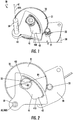
FIG. 1 is a perspective view of a compact gearbox design of a windshield wiper system (WWS) in accordance with embodiments; -
FIG. 2 is a top down view of the compact gearbox design ofFIG. 1 ; -
FIG. 3 is a schematic diagram of a controller of the WWS ofFIGS. 1 and 2 ; -
FIG. 4 is a top down view of an internally cut sector gear of the WWS ofFIGS. 1 and 2 ; and -
FIG. 5 is a flow diagram illustrating a method of operating a WWS in accordance with embodiments. - These and other advantages and features will become more apparent from the following description taken in conjunction with the drawings.
- As will be described below, a windshield wiper system (WWS) is provided to have a compact gearbox design with hard mechanical stops. The compact gearbox design includes an internally cut sector gear that is formed to define an internal geared groove. Opposite ends of the internal geared groove provide for mechanical stops and the internalization of the internal geared groove reduces an overall envelop of the gearbox design.
- With reference to
FIGS. 1 and 2 , a windshield wiper system (WWS) 10 is provided and includes a brushless direct current (BLDC)motor 20 that is operable in opposite first and second directions and includes arotatable shaft 21 with a motoroutput shaft gear 22, agear train 30 and an internallycut sector gear 40. Thegear train 30 includes afirst gear 31 and asecond gear 32. Thefirst gear 31 has a first diameter D1 (seeFIG. 2 ) and engages with the motoroutput shaft gear 22. Thesecond gear 32 has a second diameter D2 that is shorter than the first diameter D1 and rotates about a rotational axis that is common to thefirst gear 31 and thesecond gear 32. Thesecond gear 32 rotates with thefirst gear 31. The internally cutsector gear 40 is coupled with anoutput shaft 50 that connects with wiper blades of the WWS 10. The internally cutsector gear 40 is formed to define an internal gearedgroove 41 that engages with thesecond gear 32. - The
gear train 30 may be configured such that an input speed of the motoroutput shaft gear 22 is decreased by the gear ratio between thefirst gear 31 and thesecond gear 32. In addition, owing to theinternal gear groove 41 of the internally cutsector gear 40, an axis AOS of theoutput shaft 50 may be proximate to an outer diameter of thefirst gear 31. In particular, the axis AOS of theoutput shaft 50 may be within one diameter of theoutput shaft 50 from the outer diameter of thefirst gear 31. This has the effect of decreasing an overall envelope of the WWS 10 as compared to conventional systems in which the output shaft is coupled to a gear with external gearing. - As the BLDC
motor 20 drives rotation of the motoroutput shaft gear 22, the motoroutput shaft gear 22 drives rotations of thefirst gear 31 and thesecond gear 32. The engagement between thesecond gear 32 and the internal gearedgroove 41 causes the internally cutsector gear 40 to rotate about a rotational axis A1. The axis AOS of theoutput shaft 50 may extend along the rotational axis A1. The rotation of the internally cutsector gear 40 continues until thesecond gear 32 reaches anend 410 of the internal gearedgroove 41. At this point, the BLDCmotor 20 can be stopped by logic of a controller 301 (seeFIG. 3 ) to be described below or reversed such that the rotation of the internally cutsector gear 40 reverses direction with thesecond gear 32 proceeding toward anopposite end 411 of the internal gearedgroove 41. An arc-length of the internal gearedgroove 41 may exceed or only slightly exceed a required sweep angle of the blades of the WWS 10 (seeFIG. 4 ). - The internal geared
groove 41 has the opposite ends 410 and 411 and may includestoppers 42 at the opposite ends 410 and 411. Thestoppers 42 can provide a hard stop to thesecond gear 32 to indicate to thecontroller 301 that thesecond gear 32 has overreached and thus reached one of theends groove 41 and, in some cases, to indicate to thecontroller 301 in particular that theBLDC motor 20 has been driven to rotate too far in one direction. This indication can lead to overcurrent trip logic being engaged. - With reference to
FIG. 3 , thecontroller 301 may be provided as an electronic control unit (ECU) that is receptive of pilot or co-pilot input to start the WWS 10 and which is disposed and configured to operate theBLDC motor 20 in the first and second directions. Thecontroller 301 includes aprocessing unit 310, amemory unit 320 and an input/output (I/O)unit 330 by which theprocessing unit 310 is communicative with theBLDC motor 20. Thememory unit 320 has executable instructions stored thereon, which are readable and executable by theprocessing unit 310 to cause theprocessing unit 310 to operate as described herein. In particular, the executable instructions of thememory unit 320 define an overcurrent trip logic element that can be activated to being the WWS 10 to a halt when there is an overshoot leading to a locked condition and current being drawn from theBLDC motor 20 increasing. - With reference to
FIG. 4 , the internally cutsector gear 40 includes ahub portion 401, from which theoutput shaft 50 extends, and asector gear portion 402. Thesector gear portion 402 extends radially outwardly from thehub portion 401. The internal gearedgroove 41 is defined within thesector gear portion 402. As shown inFIG. 4 , thesector gear portion 402 includes aninternal diameter portion 403 that includes a smoothexterior facing surface 404, first and secondradial portions internal diameter portion 403 and which taper apart from each other with increasing distance from thehub portion 401 and anexterior diameter portion 407. The first and secondradial portions surface 408 from which astopper 42 extends inwardly. Theexterior diameter portion 407 includes internally facingteeth 409 that engage with thesecond gear 32. - With reference to
FIG. 5 , a method of operating the WWS 10 is provided. As shown inFIG. 5 , the method includes receiving a pilot or co-pilot input to operate the WWS 10 and accordingly driving theBLDC motor 20 in a first direction (501). The method further includes sensing a signal of an overcurrent condition arising from thesecond gear 32 of thegear train 30 engaging with anend 410 of the internal geared groove 41 (502) and stopping the driving of theBLDC motor 20 in the first direction (503). - In accordance with embodiments, the stopping of the driving of the
BLDC motor 20 in the first direction ofoperation 503 can also be executed in response to a determination from readings of proximal position sensors that thesecond gear 32 of thegear train 30 is close to engagement with theend 410 of the internal gearedgroove 41. - Once the driving the
BLDC motor 20 in the first direction is stopped, the method may further include driving theBLDC motor 20 in a second direction opposite the first direction (504), sensing a signal of an overcurrent condition arising from thesecond gear 32 of thegear train 30 engaging with anopposite end 411 of the internal geared groove 41 (505), stopping the driving of theBLDC motor 20 in the second direction (506) and repeating the driving of theBLDC motor 20 in the first direction (507). - In accordance with embodiments, the stopping of the driving of the
BLDC motor 20 in the second direction ofoperation 506 can also be executed in response to a new determination from readings of the proximal position sensors that thesecond gear 32 of thegear train 30 is close to engagement with theend 411 of the internal gearedgroove 41. - Benefits of the features described herein are the provision of the WWS 10 with a compact gearbox design with hard mechanical stops.
- While the disclosure is provided in detail in connection with only a limited number of embodiments, it should be readily understood that the disclosure is not limited to such disclosed embodiments. Rather, the disclosure can be modified to incorporate any number of variations, alterations, substitutions or equivalent arrangements not heretofore described, but which are commensurate with the spirit and scope of the disclosure. Additionally, while various embodiments of the disclosure have been described, it is to be understood that the exemplary embodiment(s) may include only some of the described exemplary aspects. Accordingly, the disclosure is not to be seen as limited by the foregoing description, but is only limited by the scope of the appended claims.
Claims (15)
- A windshield wiper system (WWS) (10), comprising:a brushless direct current (BLDC) motor (20) with a motor output shaft gear (22);a gear train (30) comprising a first gear (31), which has a first diameter (D1) and engages with the motor output shaft gear (22), and a second gear (32), which has a second diameter (D2) that is shorter than the first diameter (D1) and rotates with the first gear (31); andan internally cut sector gear (40), which is coupled with an output shaft (50) and formed to define an internal geared groove (41) that engages with the second gear (32).
- The WWS according to claim 1, wherein an arc-length of the internal geared groove (41) exceeds a required sweep angle of the WWS (10).
- The WWS according to claim 1 or 2, wherein the internally cut sector gear (40) comprises stoppers (42) at opposite ends (410, 411) of the internal geared groove (41).
- The WWS according to any preceding claim, further comprising a controller (301) storing overcurrent trip logic, optionally wherein mechanical interference between the second gear (32) and either opposite end (410, 411) of the internal geared groove (41) activates the overcurrent trip logic of the controller (301).
- The WWS according to any preceding claim, wherein an axis (AOS) of the output shaft (50) is proximate to an exterior diameter (D1) of the first gear (31).
- The WWS according to any preceding claim, wherein the internally cut sector gear (40) comprises:a hub portion (401) from which the output shaft (50) extends; anda sector gear portion (402), which extends radially outwardly from the hub portion (401) and in which the internal geared groove (41) is defined.
- The WWS according to claim 6, wherein the sector gear portion (402) comprises:an internal diameter portion (403) comprising a smooth exterior facing surface (404);first and second radial portions (405, 406) extending radially outwardly from the internal diameter portion (403) and apart from each other; andan exterior diameter portion (407) comprising internally facing teeth (409), optionally wherein the first and second radial portions (405, 406) respectively comprise:smooth internally facing surfaces (408); andstoppers (42) disposed along the smooth internally facing surfaces (408).
- An internally cut sector gear (40) of a windshield wiper system (WWS) (10), comprising:a hub portion (401) from which an output shaft (50) extends toward wipers of the WWS (10); anda sector gear portion (402), which extends radially outwardly from the hub portion (401) and in which an internal geared groove (41) is defined for engagement with a motor driven gear train (30).
- The internally cut sector gear (40) according to claim 8, wherein an arc-length of the internal geared groove (41) exceeds a required sweep angle of the WWS (10), and/or wherein the internally cut sector gear (40) comprises stoppers (42) at opposite ends (410, 411) of the internal geared groove (41).
- The internally cut sector gear (40) according to claim 8 or 9, wherein an axis (AOS) of the output shaft (50) is proximate to an exterior diameter (D1) of a large diameter gear (31) of the gear train (30).
- The internally cut sector gear (40) according to any of claims 8 to 10, wherein the sector gear portion (402) comprises:an internal diameter portion (403) comprising a smooth exterior facing surface (404);first and second radial portions (405, 406) extending radially outwardly from the internal diameter portion (403) and apart from each other; andan exterior diameter portion (407) comprising internally facing teeth (409), optionally wherein the first and second radial portions (405, 406) respectively comprise:smooth internally facing surfaces (408); andstoppers (42) disposed along the smooth internally facing surfaces (408).
- A method of operating a windshield wiper system (WWS) (10), comprising:driving a brushless direct current (BLDC) motor (20) with an output shaft gear (22) in a first direction with the output shaft gear (22) engaged with a gear train (30) that is, in turn, engaged with an internal geared groove (41) of an internally cut sector gear (40) that is coupled with an output shaft (50);sensing an overcurrent condition arising from the gear train (30) engaging with an end (410) of the internal geared groove (41); andstopping the driving of the BLDC motor (20) in the first direction.
- The method according to claim 12, further comprising:driving the BLDC motor (20) in a second direction opposite the first direction;sensing an overcurrent condition arising from the gear train (30) engaging with an opposite end (411) of the internal geared groove (41);stopping the driving of the BLDC motor (20) in the second direction; andrepeating the driving of the BLDC motor (20) in the first direction.
- The method according to claim 12 or 13, wherein the driving comprises:determining when the gear train (30) is close to engagement with the end (410) of the internal geared groove (41); anddriving the BLDC motor (20) in a second direction opposite the first direction;determining when the gear train (30) is close to engagement with an opposite end (411) of the internal geared groove (41); andrepeating the driving the BLDC motor (20) in the first direction.
- The method according to any of claims 12 to 14, wherein an arc-length of the internal geared groove (41) exceeds a required sweep angle of the WWS (10), and/or wherein logic for executing the sensing and the stopping is provided in a controller (301) of the BLDC motor (20).
Applications Claiming Priority (1)
| Application Number | Priority Date | Filing Date | Title |
|---|---|---|---|
| IN201811026204 | 2018-07-13 |
Publications (2)
| Publication Number | Publication Date |
|---|---|
| EP3594075A1 true EP3594075A1 (en) | 2020-01-15 |
| EP3594075B1 EP3594075B1 (en) | 2021-04-07 |
Family
ID=67262234
Family Applications (1)
| Application Number | Title | Priority Date | Filing Date |
|---|---|---|---|
| EP19186155.8A Active EP3594075B1 (en) | 2018-07-13 | 2019-07-12 | Compact gearbox design for windshield wiper system |
Country Status (2)
| Country | Link |
|---|---|
| US (1) | US11167727B2 (en) |
| EP (1) | EP3594075B1 (en) |
Families Citing this family (2)
| Publication number | Priority date | Publication date | Assignee | Title |
|---|---|---|---|---|
| CN113639994B (en) * | 2021-09-03 | 2023-06-09 | 成都秦川物联网科技股份有限公司 | Gear set meshing detection auxiliary device for smart production of electromechanical valves for gas meters |
| US12377816B1 (en) * | 2024-02-23 | 2025-08-05 | Leonardo Luis Quintero | System for removing water from windshields |
Citations (4)
| Publication number | Priority date | Publication date | Assignee | Title |
|---|---|---|---|---|
| DE3044286A1 (en) * | 1980-11-25 | 1982-06-24 | SWF-Spezialfabrik für Autozubehör Gustav Rau GmbH, 7120 Bietigheim-Bissingen | Compact drive for windscreen wiper - has main drive gear mounted on bearing on end of wiper shaft |
| US20070272787A1 (en) * | 2006-05-09 | 2007-11-29 | Huang Jian | Hose/cable reeler |
| EP2072357A2 (en) * | 2007-12-19 | 2009-06-24 | Robert Bosch Gmbh | Wipe drive and wiping system with wiper drives |
| DE102009014312A1 (en) * | 2009-03-25 | 2010-09-30 | Valeo Systèmes d'Essuyage | Electromotive auxiliary drive, in particular wiper drive |
Family Cites Families (9)
| Publication number | Priority date | Publication date | Assignee | Title |
|---|---|---|---|---|
| US2494538A (en) * | 1945-10-10 | 1950-01-17 | Baldo Louie | Window wiper apparatus |
| US2878506A (en) * | 1953-06-26 | 1959-03-24 | Anderson Co | Drive shaft mechanism for windshield wiper arms |
| US5404085A (en) * | 1992-07-10 | 1995-04-04 | Rosemount Aerospace, Inc. | Multifunction aircraft windscreen wiper control system |
| US6205612B1 (en) | 1997-10-09 | 2001-03-27 | Ut Automotive Dearborn, Inc. | Window wiper system for an automotive vehicle |
| JP4216786B2 (en) | 2004-10-06 | 2009-01-28 | 本田技研工業株式会社 | Reciprocating drive device |
| DE102010001920A1 (en) * | 2010-02-15 | 2011-08-18 | Robert Bosch GmbH, 70469 | Wiper motor control |
| DE102010001923A1 (en) | 2010-02-15 | 2011-08-18 | Robert Bosch GmbH, 70469 | Drive unit for a windshield wiper system |
| DE102015205467A1 (en) * | 2015-03-25 | 2016-09-29 | Robert Bosch Gmbh | Wiper gear, which includes a gear, a worm and an output shaft and a method with such a wiper gear |
| US20190337488A1 (en) * | 2018-05-07 | 2019-11-07 | Goodrich Corporation | Windshield wiper system with sector gear |
-
2019
- 2019-01-11 US US16/245,914 patent/US11167727B2/en active Active
- 2019-07-12 EP EP19186155.8A patent/EP3594075B1/en active Active
Patent Citations (4)
| Publication number | Priority date | Publication date | Assignee | Title |
|---|---|---|---|---|
| DE3044286A1 (en) * | 1980-11-25 | 1982-06-24 | SWF-Spezialfabrik für Autozubehör Gustav Rau GmbH, 7120 Bietigheim-Bissingen | Compact drive for windscreen wiper - has main drive gear mounted on bearing on end of wiper shaft |
| US20070272787A1 (en) * | 2006-05-09 | 2007-11-29 | Huang Jian | Hose/cable reeler |
| EP2072357A2 (en) * | 2007-12-19 | 2009-06-24 | Robert Bosch Gmbh | Wipe drive and wiping system with wiper drives |
| DE102009014312A1 (en) * | 2009-03-25 | 2010-09-30 | Valeo Systèmes d'Essuyage | Electromotive auxiliary drive, in particular wiper drive |
Also Published As
| Publication number | Publication date |
|---|---|
| US20200017075A1 (en) | 2020-01-16 |
| US11167727B2 (en) | 2021-11-09 |
| EP3594075B1 (en) | 2021-04-07 |
Similar Documents
| Publication | Publication Date | Title |
|---|---|---|
| EP3594075B1 (en) | Compact gearbox design for windshield wiper system | |
| US20110078868A1 (en) | Windshield wiper drive | |
| EP3766747B1 (en) | Dynamic wiper control | |
| EP3181415B1 (en) | Variable sweep angle motor drive | |
| ES2262010T3 (en) | OPERATING PROCEDURE OF A WINDSHIELD WASHING SYSTEM, AND THE CORRESPONDING WINDSHIELD WASHING SYSTEM. | |
| JP2009281484A (en) | Controller of range change-over mechanism | |
| US20180195603A1 (en) | Actuator With Auxiliary Motor | |
| CN107269834A (en) | Electric parking lock device | |
| JP5129477B2 (en) | Wiper motor | |
| US20210323505A1 (en) | Smart wiper system | |
| US20190337488A1 (en) | Windshield wiper system with sector gear | |
| US12168423B2 (en) | Reversible motor configured with motion stops for aircraft windshield wiper system | |
| CN206497321U (en) | Steering gear control system and steering wheel | |
| CN107614330B (en) | wiper device | |
| JP2017028919A (en) | Range switching controller | |
| US20250033599A1 (en) | Mechanical hard stop for wiper | |
| US8973605B2 (en) | Actuating device for housed or housingless valves | |
| WO2017169197A1 (en) | Motor control apparatus | |
| CN113443001B (en) | Variable stroke stop for improved worm gear durability | |
| US12545393B2 (en) | Systems for precise control of wiper | |
| JP2008094374A (en) | Wiper device | |
| JP6372958B2 (en) | Wiper system | |
| US2790333A (en) | Windshield wiper actuating mechanism | |
| JP2004058746A (en) | Vehicle steering control system | |
| JP6477091B2 (en) | Vehicle wiper device |
Legal Events
| Date | Code | Title | Description |
|---|---|---|---|
| PUAI | Public reference made under article 153(3) epc to a published international application that has entered the european phase |
Free format text: ORIGINAL CODE: 0009012 |
|
| STAA | Information on the status of an ep patent application or granted ep patent |
Free format text: STATUS: THE APPLICATION HAS BEEN PUBLISHED |
|
| AK | Designated contracting states |
Kind code of ref document: A1 Designated state(s): AL AT BE BG CH CY CZ DE DK EE ES FI FR GB GR HR HU IE IS IT LI LT LU LV MC MK MT NL NO PL PT RO RS SE SI SK SM TR |
|
| AX | Request for extension of the european patent |
Extension state: BA ME |
|
| STAA | Information on the status of an ep patent application or granted ep patent |
Free format text: STATUS: REQUEST FOR EXAMINATION WAS MADE |
|
| 17P | Request for examination filed |
Effective date: 20200709 |
|
| RBV | Designated contracting states (corrected) |
Designated state(s): AL AT BE BG CH CY CZ DE DK EE ES FI FR GB GR HR HU IE IS IT LI LT LU LV MC MK MT NL NO PL PT RO RS SE SI SK SM TR |
|
| GRAP | Despatch of communication of intention to grant a patent |
Free format text: ORIGINAL CODE: EPIDOSNIGR1 |
|
| STAA | Information on the status of an ep patent application or granted ep patent |
Free format text: STATUS: GRANT OF PATENT IS INTENDED |
|
| INTG | Intention to grant announced |
Effective date: 20201014 |
|
| GRAS | Grant fee paid |
Free format text: ORIGINAL CODE: EPIDOSNIGR3 |
|
| GRAA | (expected) grant |
Free format text: ORIGINAL CODE: 0009210 |
|
| STAA | Information on the status of an ep patent application or granted ep patent |
Free format text: STATUS: THE PATENT HAS BEEN GRANTED |
|
| AK | Designated contracting states |
Kind code of ref document: B1 Designated state(s): AL AT BE BG CH CY CZ DE DK EE ES FI FR GB GR HR HU IE IS IT LI LT LU LV MC MK MT NL NO PL PT RO RS SE SI SK SM TR |
|
| REG | Reference to a national code |
Ref country code: GB Ref legal event code: FG4D |
|
| REG | Reference to a national code |
Ref country code: AT Ref legal event code: REF Ref document number: 1379303 Country of ref document: AT Kind code of ref document: T Effective date: 20210415 Ref country code: CH Ref legal event code: EP |
|
| REG | Reference to a national code |
Ref country code: DE Ref legal event code: R096 Ref document number: 602019003726 Country of ref document: DE |
|
| REG | Reference to a national code |
Ref country code: IE Ref legal event code: FG4D |
|
| REG | Reference to a national code |
Ref country code: LT Ref legal event code: MG9D |
|
| REG | Reference to a national code |
Ref country code: NL Ref legal event code: MP Effective date: 20210407 Ref country code: AT Ref legal event code: MK05 Ref document number: 1379303 Country of ref document: AT Kind code of ref document: T Effective date: 20210407 |
|
| PG25 | Lapsed in a contracting state [announced via postgrant information from national office to epo] |
Ref country code: FI Free format text: LAPSE BECAUSE OF FAILURE TO SUBMIT A TRANSLATION OF THE DESCRIPTION OR TO PAY THE FEE WITHIN THE PRESCRIBED TIME-LIMIT Effective date: 20210407 Ref country code: LT Free format text: LAPSE BECAUSE OF FAILURE TO SUBMIT A TRANSLATION OF THE DESCRIPTION OR TO PAY THE FEE WITHIN THE PRESCRIBED TIME-LIMIT Effective date: 20210407 Ref country code: HR Free format text: LAPSE BECAUSE OF FAILURE TO SUBMIT A TRANSLATION OF THE DESCRIPTION OR TO PAY THE FEE WITHIN THE PRESCRIBED TIME-LIMIT Effective date: 20210407 Ref country code: AT Free format text: LAPSE BECAUSE OF FAILURE TO SUBMIT A TRANSLATION OF THE DESCRIPTION OR TO PAY THE FEE WITHIN THE PRESCRIBED TIME-LIMIT Effective date: 20210407 Ref country code: BG Free format text: LAPSE BECAUSE OF FAILURE TO SUBMIT A TRANSLATION OF THE DESCRIPTION OR TO PAY THE FEE WITHIN THE PRESCRIBED TIME-LIMIT Effective date: 20210707 Ref country code: NL Free format text: LAPSE BECAUSE OF FAILURE TO SUBMIT A TRANSLATION OF THE DESCRIPTION OR TO PAY THE FEE WITHIN THE PRESCRIBED TIME-LIMIT Effective date: 20210407 |
|
| PG25 | Lapsed in a contracting state [announced via postgrant information from national office to epo] |
Ref country code: PL Free format text: LAPSE BECAUSE OF FAILURE TO SUBMIT A TRANSLATION OF THE DESCRIPTION OR TO PAY THE FEE WITHIN THE PRESCRIBED TIME-LIMIT Effective date: 20210407 Ref country code: LV Free format text: LAPSE BECAUSE OF FAILURE TO SUBMIT A TRANSLATION OF THE DESCRIPTION OR TO PAY THE FEE WITHIN THE PRESCRIBED TIME-LIMIT Effective date: 20210407 Ref country code: NO Free format text: LAPSE BECAUSE OF FAILURE TO SUBMIT A TRANSLATION OF THE DESCRIPTION OR TO PAY THE FEE WITHIN THE PRESCRIBED TIME-LIMIT Effective date: 20210707 Ref country code: RS Free format text: LAPSE BECAUSE OF FAILURE TO SUBMIT A TRANSLATION OF THE DESCRIPTION OR TO PAY THE FEE WITHIN THE PRESCRIBED TIME-LIMIT Effective date: 20210407 Ref country code: SE Free format text: LAPSE BECAUSE OF FAILURE TO SUBMIT A TRANSLATION OF THE DESCRIPTION OR TO PAY THE FEE WITHIN THE PRESCRIBED TIME-LIMIT Effective date: 20210407 Ref country code: PT Free format text: LAPSE BECAUSE OF FAILURE TO SUBMIT A TRANSLATION OF THE DESCRIPTION OR TO PAY THE FEE WITHIN THE PRESCRIBED TIME-LIMIT Effective date: 20210809 Ref country code: IS Free format text: LAPSE BECAUSE OF FAILURE TO SUBMIT A TRANSLATION OF THE DESCRIPTION OR TO PAY THE FEE WITHIN THE PRESCRIBED TIME-LIMIT Effective date: 20210807 Ref country code: GR Free format text: LAPSE BECAUSE OF FAILURE TO SUBMIT A TRANSLATION OF THE DESCRIPTION OR TO PAY THE FEE WITHIN THE PRESCRIBED TIME-LIMIT Effective date: 20210708 |
|
| REG | Reference to a national code |
Ref country code: DE Ref legal event code: R097 Ref document number: 602019003726 Country of ref document: DE |
|
| PG25 | Lapsed in a contracting state [announced via postgrant information from national office to epo] |
Ref country code: EE Free format text: LAPSE BECAUSE OF FAILURE TO SUBMIT A TRANSLATION OF THE DESCRIPTION OR TO PAY THE FEE WITHIN THE PRESCRIBED TIME-LIMIT Effective date: 20210407 Ref country code: ES Free format text: LAPSE BECAUSE OF FAILURE TO SUBMIT A TRANSLATION OF THE DESCRIPTION OR TO PAY THE FEE WITHIN THE PRESCRIBED TIME-LIMIT Effective date: 20210407 Ref country code: SK Free format text: LAPSE BECAUSE OF FAILURE TO SUBMIT A TRANSLATION OF THE DESCRIPTION OR TO PAY THE FEE WITHIN THE PRESCRIBED TIME-LIMIT Effective date: 20210407 Ref country code: DK Free format text: LAPSE BECAUSE OF FAILURE TO SUBMIT A TRANSLATION OF THE DESCRIPTION OR TO PAY THE FEE WITHIN THE PRESCRIBED TIME-LIMIT Effective date: 20210407 Ref country code: CZ Free format text: LAPSE BECAUSE OF FAILURE TO SUBMIT A TRANSLATION OF THE DESCRIPTION OR TO PAY THE FEE WITHIN THE PRESCRIBED TIME-LIMIT Effective date: 20210407 Ref country code: RO Free format text: LAPSE BECAUSE OF FAILURE TO SUBMIT A TRANSLATION OF THE DESCRIPTION OR TO PAY THE FEE WITHIN THE PRESCRIBED TIME-LIMIT Effective date: 20210407 Ref country code: SM Free format text: LAPSE BECAUSE OF FAILURE TO SUBMIT A TRANSLATION OF THE DESCRIPTION OR TO PAY THE FEE WITHIN THE PRESCRIBED TIME-LIMIT Effective date: 20210407 |
|
| PLBE | No opposition filed within time limit |
Free format text: ORIGINAL CODE: 0009261 |
|
| STAA | Information on the status of an ep patent application or granted ep patent |
Free format text: STATUS: NO OPPOSITION FILED WITHIN TIME LIMIT |
|
| 26N | No opposition filed |
Effective date: 20220110 |
|
| PG25 | Lapsed in a contracting state [announced via postgrant information from national office to epo] |
Ref country code: MC Free format text: LAPSE BECAUSE OF FAILURE TO SUBMIT A TRANSLATION OF THE DESCRIPTION OR TO PAY THE FEE WITHIN THE PRESCRIBED TIME-LIMIT Effective date: 20210407 |
|
| REG | Reference to a national code |
Ref country code: BE Ref legal event code: MM Effective date: 20210731 |
|
| PG25 | Lapsed in a contracting state [announced via postgrant information from national office to epo] |
Ref country code: IS Free format text: LAPSE BECAUSE OF FAILURE TO SUBMIT A TRANSLATION OF THE DESCRIPTION OR TO PAY THE FEE WITHIN THE PRESCRIBED TIME-LIMIT Effective date: 20210807 Ref country code: LU Free format text: LAPSE BECAUSE OF NON-PAYMENT OF DUE FEES Effective date: 20210712 Ref country code: AL Free format text: LAPSE BECAUSE OF FAILURE TO SUBMIT A TRANSLATION OF THE DESCRIPTION OR TO PAY THE FEE WITHIN THE PRESCRIBED TIME-LIMIT Effective date: 20210407 |
|
| PG25 | Lapsed in a contracting state [announced via postgrant information from national office to epo] |
Ref country code: IT Free format text: LAPSE BECAUSE OF FAILURE TO SUBMIT A TRANSLATION OF THE DESCRIPTION OR TO PAY THE FEE WITHIN THE PRESCRIBED TIME-LIMIT Effective date: 20210407 Ref country code: IE Free format text: LAPSE BECAUSE OF NON-PAYMENT OF DUE FEES Effective date: 20210712 Ref country code: BE Free format text: LAPSE BECAUSE OF NON-PAYMENT OF DUE FEES Effective date: 20210731 |
|
| REG | Reference to a national code |
Ref country code: CH Ref legal event code: PL |
|
| PG25 | Lapsed in a contracting state [announced via postgrant information from national office to epo] |
Ref country code: LI Free format text: LAPSE BECAUSE OF NON-PAYMENT OF DUE FEES Effective date: 20220731 Ref country code: CH Free format text: LAPSE BECAUSE OF NON-PAYMENT OF DUE FEES Effective date: 20220731 |
|
| PG25 | Lapsed in a contracting state [announced via postgrant information from national office to epo] |
Ref country code: CY Free format text: LAPSE BECAUSE OF FAILURE TO SUBMIT A TRANSLATION OF THE DESCRIPTION OR TO PAY THE FEE WITHIN THE PRESCRIBED TIME-LIMIT Effective date: 20210407 |
|
| PG25 | Lapsed in a contracting state [announced via postgrant information from national office to epo] |
Ref country code: HU Free format text: LAPSE BECAUSE OF FAILURE TO SUBMIT A TRANSLATION OF THE DESCRIPTION OR TO PAY THE FEE WITHIN THE PRESCRIBED TIME-LIMIT; INVALID AB INITIO Effective date: 20190712 |
|
| PG25 | Lapsed in a contracting state [announced via postgrant information from national office to epo] |
Ref country code: MK Free format text: LAPSE BECAUSE OF FAILURE TO SUBMIT A TRANSLATION OF THE DESCRIPTION OR TO PAY THE FEE WITHIN THE PRESCRIBED TIME-LIMIT Effective date: 20210407 |
|
| PG25 | Lapsed in a contracting state [announced via postgrant information from national office to epo] |
Ref country code: MT Free format text: LAPSE BECAUSE OF FAILURE TO SUBMIT A TRANSLATION OF THE DESCRIPTION OR TO PAY THE FEE WITHIN THE PRESCRIBED TIME-LIMIT Effective date: 20210407 |
|
| PGFP | Annual fee paid to national office [announced via postgrant information from national office to epo] |
Ref country code: GB Payment date: 20250619 Year of fee payment: 7 |
|
| PGFP | Annual fee paid to national office [announced via postgrant information from national office to epo] |
Ref country code: FR Payment date: 20250620 Year of fee payment: 7 |
|
| PGFP | Annual fee paid to national office [announced via postgrant information from national office to epo] |
Ref country code: DE Payment date: 20250620 Year of fee payment: 7 |
|
| PG25 | Lapsed in a contracting state [announced via postgrant information from national office to epo] |
Ref country code: TR Free format text: LAPSE BECAUSE OF FAILURE TO SUBMIT A TRANSLATION OF THE DESCRIPTION OR TO PAY THE FEE WITHIN THE PRESCRIBED TIME-LIMIT Effective date: 20210407 |
|
| P01 | Opt-out of the competence of the unified patent court (upc) registered |
Free format text: CASE NUMBER: UPC_APP_0018049_3594075/2025 Effective date: 20251217 |