EP3593909A1 - Apparatus and method for cleaning and recovering paint in painting plants - Google Patents
Apparatus and method for cleaning and recovering paint in painting plants Download PDFInfo
- Publication number
- EP3593909A1 EP3593909A1 EP19184453.9A EP19184453A EP3593909A1 EP 3593909 A1 EP3593909 A1 EP 3593909A1 EP 19184453 A EP19184453 A EP 19184453A EP 3593909 A1 EP3593909 A1 EP 3593909A1
- Authority
- EP
- European Patent Office
- Prior art keywords
- paint
- trolley
- cleaning
- solvent
- recovery
- Prior art date
- Legal status (The legal status is an assumption and is not a legal conclusion. Google has not performed a legal analysis and makes no representation as to the accuracy of the status listed.)
- Granted
Links
Images


Classifications
-
- B—PERFORMING OPERATIONS; TRANSPORTING
- B05—SPRAYING OR ATOMISING IN GENERAL; APPLYING FLUENT MATERIALS TO SURFACES, IN GENERAL
- B05B—SPRAYING APPARATUS; ATOMISING APPARATUS; NOZZLES
- B05B14/00—Arrangements for collecting, re-using or eliminating excess spraying material
- B05B14/20—Arrangements for collecting, re-using or eliminating excess spraying material from moving belts, e.g. filtering belts or conveying belts
-
- B—PERFORMING OPERATIONS; TRANSPORTING
- B05—SPRAYING OR ATOMISING IN GENERAL; APPLYING FLUENT MATERIALS TO SURFACES, IN GENERAL
- B05B—SPRAYING APPARATUS; ATOMISING APPARATUS; NOZZLES
- B05B15/00—Details of spraying plant or spraying apparatus not otherwise provided for; Accessories
- B05B15/50—Arrangements for cleaning; Arrangements for preventing deposits, drying-out or blockage; Arrangements for detecting improper discharge caused by the presence of foreign matter
-
- B—PERFORMING OPERATIONS; TRANSPORTING
- B05—SPRAYING OR ATOMISING IN GENERAL; APPLYING FLUENT MATERIALS TO SURFACES, IN GENERAL
- B05C—APPARATUS FOR APPLYING FLUENT MATERIALS TO SURFACES, IN GENERAL
- B05C11/00—Component parts, details or accessories not specifically provided for in groups B05C1/00 - B05C9/00
- B05C11/10—Storage, supply or control of liquid or other fluent material; Recovery of excess liquid or other fluent material
- B05C11/1039—Recovery of excess liquid or other fluent material; Controlling means therefor
-
- B—PERFORMING OPERATIONS; TRANSPORTING
- B65—CONVEYING; PACKING; STORING; HANDLING THIN OR FILAMENTARY MATERIAL
- B65G—TRANSPORT OR STORAGE DEVICES, e.g. CONVEYORS FOR LOADING OR TIPPING, SHOP CONVEYOR SYSTEMS OR PNEUMATIC TUBE CONVEYORS
- B65G45/00—Lubricating, cleaning, or clearing devices
- B65G45/10—Cleaning devices
- B65G45/22—Cleaning devices comprising fluid applying means
-
- B—PERFORMING OPERATIONS; TRANSPORTING
- B65—CONVEYING; PACKING; STORING; HANDLING THIN OR FILAMENTARY MATERIAL
- B65G—TRANSPORT OR STORAGE DEVICES, e.g. CONVEYORS FOR LOADING OR TIPPING, SHOP CONVEYOR SYSTEMS OR PNEUMATIC TUBE CONVEYORS
- B65G45/00—Lubricating, cleaning, or clearing devices
- B65G45/10—Cleaning devices
- B65G45/24—Cleaning devices comprising plural diverse cleaning devices
-
- B—PERFORMING OPERATIONS; TRANSPORTING
- B65—CONVEYING; PACKING; STORING; HANDLING THIN OR FILAMENTARY MATERIAL
- B65G—TRANSPORT OR STORAGE DEVICES, e.g. CONVEYORS FOR LOADING OR TIPPING, SHOP CONVEYOR SYSTEMS OR PNEUMATIC TUBE CONVEYORS
- B65G45/00—Lubricating, cleaning, or clearing devices
- B65G45/10—Cleaning devices
- B65G45/12—Cleaning devices comprising scrapers
-
- B—PERFORMING OPERATIONS; TRANSPORTING
- B65—CONVEYING; PACKING; STORING; HANDLING THIN OR FILAMENTARY MATERIAL
- B65G—TRANSPORT OR STORAGE DEVICES, e.g. CONVEYORS FOR LOADING OR TIPPING, SHOP CONVEYOR SYSTEMS OR PNEUMATIC TUBE CONVEYORS
- B65G45/00—Lubricating, cleaning, or clearing devices
- B65G45/10—Cleaning devices
- B65G45/26—Cleaning devices for gathering residue after cleaning
-
- Y—GENERAL TAGGING OF NEW TECHNOLOGICAL DEVELOPMENTS; GENERAL TAGGING OF CROSS-SECTIONAL TECHNOLOGIES SPANNING OVER SEVERAL SECTIONS OF THE IPC; TECHNICAL SUBJECTS COVERED BY FORMER USPC CROSS-REFERENCE ART COLLECTIONS [XRACs] AND DIGESTS
- Y02—TECHNOLOGIES OR APPLICATIONS FOR MITIGATION OR ADAPTATION AGAINST CLIMATE CHANGE
- Y02P—CLIMATE CHANGE MITIGATION TECHNOLOGIES IN THE PRODUCTION OR PROCESSING OF GOODS
- Y02P70/00—Climate change mitigation technologies in the production process for final industrial or consumer products
- Y02P70/10—Greenhouse gas [GHG] capture, material saving, heat recovery or other energy efficient measures, e.g. motor control, characterised by manufacturing processes, e.g. for rolling metal or metal working
Definitions
- EP1964794B1 of the same applicant describes a cleaning system of the belt conveying said pieces.
- Patent application IT102016000094514 in the name of the same applicant, describes a system wherein the function of paint recovery and cleaning are independent so as to provide a plurality of independent recovery units, so that the cleaning of a cleaning or recovery unit can be performed without production stop. Said system is preferably laterally extracted.
- Aim of the present invention is providing an improved paint recovery and cleaning trolley, having the smallest encumbrance possible and the best efficiency of paint recovery and cleaning operation.
- the paint recovery and cleaning system comprises just one paint recovery and cleaning trolley, wherein the functions of paint recovery and cleaning of the conveying belt are integrated, providing a cleaning system provided with the best efficacy, and a minimal encumbrance.
- Said four components form a chamber having the shape of a triangular prism, whose rectangular faces, made of said reverse roller, doctor blades and belt generate a continuous closed surface, while the two opposed triangular bases are open.
- Said configuration which is open at the two opposed end in form of triangular bases placed on the sides of the apparatus for applying paint, allows a limited aeration that reduces the evaporation of the solvent.
- said trolley can occupy different positions with respect to the apparatus for applying paint:
- the method according to the present invention comprises the following steps:
- a first advantage of the present invention is the possibility of preventing the production stop connected with the cleaning and maintenance of paint recovery and cleaning trolleys. This is particularly advantageous in complex production lines comprising a plurality of apparatuses placed in series, wherein the stop of a single apparatus involves the stopping of all the apparatuses belonging to the production line.
- a second advantage is providing a modular solution to the problem, preferably providing at least two paint recovery and cleaning units, one of which is working while the other can be extracted for maintenance, even when the paint applying apparatus is working.
- the trolley which underwent maintenance, already available in an inactive inserted position is ready to be used for a fast colour change with recovery of the paint of a different colour, without the need to clean the trolley used up to that moment.
- the paint applying apparatus is provided with three trolleys, two of which are inserted in the paint applying apparatus, while the third can undergo maintenance in a cleaning station remote from the paint applying apparatus.
- a third advantage is that the complete extraction of the cleaning trolley from the apparatus is eased in order to move it to a cleaning station remote from the paint applying apparatus, thanks to the fact that the trolley is provided with a ground support and a guide system for the lateral sliding of the trolley.
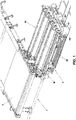
- FIG 1 shows a preferred embodiment, wherein an apparatus 1 for applying paint, comprising a conveying belt 2 of the (not shown) pieces to be painted, is provided with two paint recovery and cleaning trolleys 3, 33 according to the present invention.
- said trolleys 3, 33 are shown in the lateral extracted position, while in order to carry out the paint recovery and cleaning they must be shifted under the conveying belt 2, up to their complete alignment with the conveying belt itself.
- the conveying belt 2 of the pieces to be painted is typically a closed belt, which is moved by two rollers, one of which is motorized (not shown) and an idle roller 8 (visible in Figures 2 and 3 ).
- Said solution is well known in the art, and provides an upper outward section of the belt, on which the pieces to be painted lie, and a lower return section (visible in Figures 2 and 3 ).
- FIG 2 shows in a lateral view said two paint recovery and cleaning trolleys 3, 33 in the inserted, but not lifted, position under the conveying belt 2. It is worthwhile specifying that, in order to perform paint recovery and cleaning, each trolley 3, 33 must first be inserted completely under said conveying belt 2, and second lifted so that rollers and doctor blades come into direct contact with the conveying belt 2 to be cleaned.
- the position of the trolleys 3, 33 shown in Figure 2 can be defined inserted inactive position.
- the two trolleys 3, 33 are actually equal, they are shown in a different way in Figure 2 : the first trolley 3 is shown without its lateral side 4, which is visible for the second trolley 33. To said side 4 a tongue 5 is fastened, which coupling with a plate 6 allows the lifting, through a pneumatic cylinder 7, of the single trolley 3, 33 in its operative position, wherein the trolley is in contact with the conveying belt 2.
- Each trolley 3, 33 is provided with its own independent lifting system (the cylinder of the second trolley 33 is not visible in the Figure).
- the lifting systems 7 are preferably integral with the frame of the conveying system, because in this way, when in operative position, the system is overall more rigid, and the relative position of the trolley with respect to the conveying belt is more reliable and constant over time.
- the pneumatic cylinder 7 and all the lifting mechanism are placed between the outward section and the lower return section of the conveying belt 2.
- Figure 3 shows a detail of paint recovery and cleaning trolleys 3, 33 in their working position, i.e. inserted and lifted, wherein the rollers and the doctor blades are in contact with the lower return section of the belt 2 conveying the pieces to be painted. It is worthwhile specifying that trolleys 3, 33 are equal, work in the same way, and are interchangeable.
- each trolley 3, 33 comprises two subunits 21, 22: the first subunit 21 recovers paint, while the second subunit 22 cleans the conveying belt 2.
- the vertical dotted line allows to better distinguish the paint recovery subunit 21 from the cleaning subunit 22.
- the said two subunits 21, 22 have the same components, which for the first subunit 21 are preceded by numeral 1, while for the subunit 22 are preceded by numeral 2.
- the components doctor blade 14, plate 15, belt 16 are missing, in that they are characteristic of paint recovery and channelling, as the paint is recovered by the subunit 21 only.
- paint is recovered, through a reverse roller 19, a doctor blade 10, a doctor blade 11, a nozzle 13 and a hopper 12.
- Said doctor blade 11 is tangential with respect to said reverse roller 19, said doctor blade 10 is oblique with respect to the return section of the conveying belt 2; said doctor blades 10 and 11 lay on a same plane, which is one of the rectangular sides of the prismatic chamber containing solvent.
- the Figure shows an idle roller 8, which is part of the moving system of the conveying belt 2.
- Said reverse roller 19 is motorized with a rotation such that, in the contact point between said roller and conveying belt, the reverse roller 19 is provided with a tangential motion opposed to the advancing of the belt 2.
- the said roller 19 can remove said paint from the belt 2.
- a black arrow shows their direction of rotation.
- the doctor blade 11 In contact with said motorized reverse roller 19 there is provided the doctor blade 11, tangentially adhering to said reverse roller 19 for all its length.
- the doctor blade 10 In contact with the conveying belt 2 there is provided the doctor blade 10 that dries the conveying belt 2 after paint recovery. At least a nozzle 13 supplies a solvent compatible with the paint in use.
- Said doctor blade 10, reverse roller 19, doctor blade 11 and conveying belt 2 form a closed chamber for all the length of the roller 19 and belt 2.
- Said closed chamber contains the solvent provided by the nozzle 13, which accumulates in the contact zone between said reverse roller 19 and doctor blade 11, wetting the surface of the roller 19, which in its turn wets the belt 2 with the solvent. This facilitates the removal of paint, occurring through the doctor blade 10.
- the solvent accumulated in the contact zone between the reverse roller 19 and the doctor blade 11 drains from the triangular lateral apertures of the chamber, so as to generate a continuous renewal of solvent, which gathers in a solvent recovery hopper 12. From said hopper 12, through gravity, the solvent overflown from the closed chamber through a collector 125 and a following funnel 126 is collected in a reservoir 131 for solvent recovery.
- the solvent collected in said reservoir 131 can be reintroduced in the closed chamber formed by the components reverse roller 19, doctor blade 10, doctor blade 11, belt 2 thanks to the action of a (not shown) circuit pump, again through the nozzle 13.
- Said belt 16 is a motorized belt conveying said paint towards another doctor blade 17 (shown in Figure 4 ), which makes it fall into a paint collecting reservoir 130.
- the components of said paint recovery subunit 21 are substantially duplicated in the cleaning subunit 22 in the trolley 3 or 33, with a further reverse roller 29, a doctor blade 210, a doctor blade 211, a hopper 212, a nozzle 213, which work exactly in the same way already described above.
- the cleaning subunit 22 allows a fine cleaning of the conveying belt 2. From the hopper 212 for cleaning solvent collection, the cleaning solvent through a collector 225 is collected by a funnel 226 to be collected in a solvent recovery reservoir 231.
- this second cleaning subunit 22 comprising the components reverse roller 29, doctor blade 210, doctor blade 211, doctor blade 212, nozzle 213, collector 225, funnel 226, solvent recovery collector 231, a solvent different from that used in the paint recovery subunit 21 can be used.
- Said paint recovery subunit 21 comprises the components reverse roller 19, doctor blade 10, doctor blade 11, hopper 12, nozzle 13, collector 125, funnel 126, solvent recovery reservoir 131. This is possible because the solvent is then channelled to a solvent reservoir 231 different from said solvent reservoir 131. This separation of path and reservoirs has the advantage of not polluting the paint recovered with this, possibly different, second solvent.
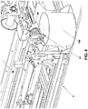
- Figure 4 shows the conveying belt 16 conveying the recovered paint, which falls from plate 15.
- the doctor blade 17 transfers the paint recovered from belt 16 to a container 130 for paint recovery through a mechanical action of scraping and subsequent fall into the paint recovery reservoir 130.
- just one paint recovery and cleaning trolley 3 can be used, working in the above-described way.
- two paint recovery and cleaning trolleys 3 and 33 there are provided two paint recovery and cleaning trolleys 3 and 33, with alternate working: when the first trolley 3 is in the operative inserted and lifted position, the second trolley 33 can be in the inactive inserted position, or can be absent in that it is in a cleaning station remote from the paint applying apparatus.
- the same apparatus 1, which provides the presence of two paint recovery and cleaning trolley 3, 33 is bought by a customer provided with just one trolley 3, and the space normally occupied by the trolley 33 is empty.
- the customer can use the two paint recovery and cleaning trolley 3 and 33 at the same time, for an even deeper paint recovery and cleaning.
- the final customer buys the apparatus for applying paint provided with three paint recovery and cleaning trolleys 3, 33, so that the space available for said trolleys is always occupied by two trolleys, while the third paint recovery and cleaning trolley is an a cleaning station remote from the paint applying apparatus.
- Paint applying apparatus Conveying belt of the pieces to be painted 3, 33 Paint recovery and cleaning trolley 4 Side 5 Tongue 6 Plate 7 Pneumatic cylinder 8 Idle roller Paint recovery subunit 21 Cleaning subunit 22 19 reverse roller 29 reverse roller 10 doctor blade 210 doctor blade 11 doctor blade 211 doctor blade 12 hopper 212 hopper 13 nozzle 213 nozzle 14 doctor blade 225 collector 15 plate 226 funnel 16 belt 231 solvent recovery reservoir 17 doctor blade 125 collector 126 funnel 130 paint recovery reservoir 131 solvent recovery reservoir
Landscapes
- Engineering & Computer Science (AREA)
- Mechanical Engineering (AREA)
- Coating Apparatus (AREA)
- Details Or Accessories Of Spraying Plant Or Apparatus (AREA)
- Cleaning By Liquid Or Steam (AREA)
- Application Of Or Painting With Fluid Materials (AREA)
- Filtering Of Dispersed Particles In Gases (AREA)
Abstract
Description
- The present invention relates to the technical field of the apparatuses for painting pieces made of sundry materials (wood, glass, fibrocement, etc.). In particular, the invention relates to an extractable trolley for the cleaning of the conveying system of the pieces and for recovering paint.
- Apparatuses provided with a cleaning trolley, with different possibilities of lateral and frontal access, are known in the art. Generally, frontal access trolleys require a production stop in order to access said trolleys.
-
EP1964794B1 of the same applicant describes a cleaning system of the belt conveying said pieces. - Patent application
IT102016000094514 - Nonetheless, practice showed the limits of the known art, in particular the encumbrance of the second solution, and the imperfect efficiency of paint recovery for the first solution.
- Aim of the present invention is providing an improved paint recovery and cleaning trolley, having the smallest encumbrance possible and the best efficiency of paint recovery and cleaning operation.
- This object is achieved by an apparatus and a method having the features of the independent claims. Advantageous embodiments and refinements are specified in claims dependent thereon.
- The paint recovery and cleaning system according to the present invention comprises just one paint recovery and cleaning trolley, wherein the functions of paint recovery and cleaning of the conveying belt are integrated, providing a cleaning system provided with the best efficacy, and a minimal encumbrance.
- The paint recovery and cleaning system according to the present invention provides the presence, in just one trolley, of a subunit for paint recovery, and of a subunit for the fine cleaning of the conveying belt. Said subunits are very similar, providing the cooperation of a reverse roller removing paint from the return section of the conveying belt, a doctor blade removing the solvent from the conveying belt, solvent that is supplied by a nozzle, a doctor blade tangentially adhering to said roller for its whole length. Said four components (reverse roller, drying doctor blade, adhering doctor blade and return section of the conveying belt) form a chamber having the shape of a triangular prism, whose rectangular faces, made of said reverse roller, doctor blades and belt generate a continuous closed surface, while the two opposed triangular bases are open. Said configuration, which is open at the two opposed end in form of triangular bases placed on the sides of the apparatus for applying paint, allows a limited aeration that reduces the evaporation of the solvent.
- It is worthwhile mentioning that said trolley can occupy different positions with respect to the apparatus for applying paint:
- Operative position, wherein said trolley is totally inserted under said conveying belt, and the paint recovery subunit and cleaning subunits are lifted so that they are in contact with the lower return section of said conveying belt;
- Inactive inserted position, wherein said trolley is totally inserted under said conveying belt, but the paint recovery subunit and cleaning subunit are lowered so that they are not in contact with the lower return section of said conveying belt;
- Lateral extracted position, wherein said trolley is totally extracted from the apparatus for applying paint.
- It is worthwhile mentioning that the space under the conveying belt is very limited, and the construction of the trolley according to the present invention was optimized in order to make every single paint recovery and cleaning trolley as compact as possible. In a preferred configuration, the trolley is provided in two specimens, so that one trolley placed in the working position in contact with the conveying belt can be used, while a second trolley is maintained in a resting position, not in contact with the conveying belt. This solution has the advantage to allow the maintenance of one of said two trolleys while the other is used for paint recovery and cleaning, without the need to stop the paint applying apparatus. Nonetheless, it is worthwhile specifying that the apparatus can perfectly work even if it is provided with just one paint recovery and cleaning trolley.
- The method according to the present invention comprises the following steps:
- Inserting a paint recovery and cleaning trolley laterally with respect to the advancing direction of the pieces to be painted;
- Bringing the respective roller and doctor blade of said trolley into contact with the conveying belt to be cleaned;
- Using the paint recovery and cleaning trolley for the desired time;
- Interrupting the contact between roller and doctor blade with the conveying belt;
- Laterally extracting the paint recovery and cleaning trolley;
- A first advantage of the present invention is the possibility of preventing the production stop connected with the cleaning and maintenance of paint recovery and cleaning trolleys. This is particularly advantageous in complex production lines comprising a plurality of apparatuses placed in series, wherein the stop of a single apparatus involves the stopping of all the apparatuses belonging to the production line.
- A second advantage is providing a modular solution to the problem, preferably providing at least two paint recovery and cleaning units, one of which is working while the other can be extracted for maintenance, even when the paint applying apparatus is working. Alternatively, the trolley which underwent maintenance, already available in an inactive inserted position, is ready to be used for a fast colour change with recovery of the paint of a different colour, without the need to clean the trolley used up to that moment.
- In a particularly preferred solution, the paint applying apparatus is provided with three trolleys, two of which are inserted in the paint applying apparatus, while the third can undergo maintenance in a cleaning station remote from the paint applying apparatus.
- A third advantage is that the complete extraction of the cleaning trolley from the apparatus is eased in order to move it to a cleaning station remote from the paint applying apparatus, thanks to the fact that the trolley is provided with a ground support and a guide system for the lateral sliding of the trolley.
- Further advantages and properties of the present invention are disclosed in the following description, in which exemplary embodiments of the present invention are explained in detail based on the drawings:
- Figure 1
- Axonometric view of an apparatus for applying paint with two paint recovery and cleaning trolleys in the extracted position;
- Figure 2
- Lateral view of said two paint recovery and cleaning trolleys, both in line with the conveying belt;
- Figure 3
- Lateral view of a detail of the rollers and doctor blades for paint recovery and cleaning;
- Figure 4
- Axonometric view of a paint recovery and cleaning trolley, in the area of channelling and collection of the recovered paint.
-
Figure 1 shows a preferred embodiment, wherein an apparatus 1 for applying paint, comprising aconveying belt 2 of the (not shown) pieces to be painted, is provided with two paint recovery andcleaning trolleys 3, 33 according to the present invention. InFigure 1 saidtrolleys 3, 33 are shown in the lateral extracted position, while in order to carry out the paint recovery and cleaning they must be shifted under theconveying belt 2, up to their complete alignment with the conveying belt itself. - The
conveying belt 2 of the pieces to be painted is typically a closed belt, which is moved by two rollers, one of which is motorized (not shown) and an idle roller 8 (visible inFigures 2 and3 ). Said solution is well known in the art, and provides an upper outward section of the belt, on which the pieces to be painted lie, and a lower return section (visible inFigures 2 and3 ). - While in use, on the pieces to be painted a paint is applied, which falls undesirably on the
conveying belt 2, too, which therefore must be cleaned in order not to soil the following pieces to be painted. As a consequence, the return lower section of the belt is cleaned using the paint recovery and cleaning trolleys according to the present invention. -
Figure 2 shows in a lateral view said two paint recovery andcleaning trolleys 3, 33 in the inserted, but not lifted, position under theconveying belt 2. It is worthwhile specifying that, in order to perform paint recovery and cleaning, eachtrolley 3, 33 must first be inserted completely under saidconveying belt 2, and second lifted so that rollers and doctor blades come into direct contact with theconveying belt 2 to be cleaned. The position of thetrolleys 3, 33 shown inFigure 2 can be defined inserted inactive position. - Although the two
trolleys 3, 33 are actually equal, they are shown in a different way inFigure 2 : the first trolley 3 is shown without its lateral side 4, which is visible for thesecond trolley 33. To said side 4 a tongue 5 is fastened, which coupling with aplate 6 allows the lifting, through a pneumatic cylinder 7, of thesingle trolley 3, 33 in its operative position, wherein the trolley is in contact with theconveying belt 2. Eachtrolley 3, 33 is provided with its own independent lifting system (the cylinder of thesecond trolley 33 is not visible in the Figure). The lifting systems 7 are preferably integral with the frame of the conveying system, because in this way, when in operative position, the system is overall more rigid, and the relative position of the trolley with respect to the conveying belt is more reliable and constant over time. - In order to reduce the encumbrance, the pneumatic cylinder 7 and all the lifting mechanism are placed between the outward section and the lower return section of the
conveying belt 2. - When a paint recovery and
cleaning trolley 3, 33 is in the extracted position shown inFigure 1 , all the (electric, pneumatic) supplies are connected. Nonetheless, in this position the cleaning of the trolley can be performed without the need to disconnect said supplies, which allows to perform a faster maintenance and cleaning of the trolley. When trolleys are connected to the painting apparatus, the possibility of moving the rollers of the trolley and the circulation of solvent can be exploited. When connected to, and supplied by, the painting apparatus 1, the trolley can perform all operation. Nonetheless, disconnecting the supplies and completely removing thetrolley 3, 33 is possible, in order to bring it to a cleaning and maintenance station remote from the paint applying apparatus 1. This to allow the use of further tools, like e.g. a pressure washer, for a deeper cleaning oftrolleys 3, 33. -
Figure 3 shows a detail of paint recovery andcleaning trolleys 3, 33 in their working position, i.e. inserted and lifted, wherein the rollers and the doctor blades are in contact with the lower return section of thebelt 2 conveying the pieces to be painted. It is worthwhile specifying thattrolleys 3, 33 are equal, work in the same way, and are interchangeable. - Moreover, it is worthwhile specifying that each
trolley 3, 33 comprises twosubunits 21, 22: thefirst subunit 21 recovers paint, while thesecond subunit 22 cleans the conveyingbelt 2. The vertical dotted line allows to better distinguish thepaint recovery subunit 21 from the cleaningsubunit 22. The said twosubunits first subunit 21 are preceded by numeral 1, while for thesubunit 22 are preceded bynumeral 2. In the cleaningsubunit 22 thecomponents doctor blade 14,plate 15,belt 16 are missing, in that they are characteristic of paint recovery and channelling, as the paint is recovered by thesubunit 21 only. - In a first step in the
subunit 21 paint is recovered, through areverse roller 19, adoctor blade 10, a doctor blade 11, anozzle 13 and ahopper 12. Said doctor blade 11 is tangential with respect to saidreverse roller 19, saiddoctor blade 10 is oblique with respect to the return section of the conveyingbelt 2; saiddoctor blades 10 and 11 lay on a same plane, which is one of the rectangular sides of the prismatic chamber containing solvent. In particular, the Figure shows anidle roller 8, which is part of the moving system of the conveyingbelt 2. Saidreverse roller 19 is motorized with a rotation such that, in the contact point between said roller and conveying belt, thereverse roller 19 is provided with a tangential motion opposed to the advancing of thebelt 2. In this way, the saidroller 19 can remove said paint from thebelt 2. For both rollers, a black arrow shows their direction of rotation. In contact with said motorizedreverse roller 19 there is provided the doctor blade 11, tangentially adhering to saidreverse roller 19 for all its length. In contact with the conveyingbelt 2 there is provided thedoctor blade 10 that dries the conveyingbelt 2 after paint recovery. At least anozzle 13 supplies a solvent compatible with the paint in use. - Said
doctor blade 10,reverse roller 19, doctor blade 11 and conveyingbelt 2 form a closed chamber for all the length of theroller 19 andbelt 2. Said closed chamber contains the solvent provided by thenozzle 13, which accumulates in the contact zone between saidreverse roller 19 and doctor blade 11, wetting the surface of theroller 19, which in its turn wets thebelt 2 with the solvent. This facilitates the removal of paint, occurring through thedoctor blade 10. The solvent accumulated in the contact zone between thereverse roller 19 and the doctor blade 11 drains from the triangular lateral apertures of the chamber, so as to generate a continuous renewal of solvent, which gathers in asolvent recovery hopper 12. From saidhopper 12, through gravity, the solvent overflown from the closed chamber through acollector 125 and a followingfunnel 126 is collected in areservoir 131 for solvent recovery. - The solvent collected in said
reservoir 131 can be reintroduced in the closed chamber formed by the components reverseroller 19,doctor blade 10, doctor blade 11,belt 2 thanks to the action of a (not shown) circuit pump, again through thenozzle 13. - The paint accumulated on the conveying
belt 2, when comes into contact withreverse roller 19, is mechanically removed accumulating on theroller 19 itself, from which it is removed by adoctor blade 14, which is secant to theroller 19, to convey it on aplate 15 which makes it fall on abelt 16. Saidbelt 16 is a motorized belt conveying said paint towards another doctor blade 17 (shown inFigure 4 ), which makes it fall into apaint collecting reservoir 130. - The components of said
paint recovery subunit 21 are substantially duplicated in the cleaningsubunit 22 in thetrolley 3 or 33, with a furtherreverse roller 29, adoctor blade 210, adoctor blade 211, ahopper 212, anozzle 213, which work exactly in the same way already described above. The cleaningsubunit 22 allows a fine cleaning of the conveyingbelt 2. From thehopper 212 for cleaning solvent collection, the cleaning solvent through acollector 225 is collected by afunnel 226 to be collected in asolvent recovery reservoir 231. In thissecond cleaning subunit 22, comprising the components reverseroller 29,doctor blade 210,doctor blade 211,doctor blade 212,nozzle 213,collector 225, funnel 226,solvent recovery collector 231, a solvent different from that used in thepaint recovery subunit 21 can be used. Saidpaint recovery subunit 21 comprises the components reverseroller 19,doctor blade 10, doctor blade 11,hopper 12,nozzle 13,collector 125, funnel 126,solvent recovery reservoir 131. This is possible because the solvent is then channelled to asolvent reservoir 231 different from saidsolvent reservoir 131. This separation of path and reservoirs has the advantage of not polluting the paint recovered with this, possibly different, second solvent. -
Figure 4 shows the conveyingbelt 16 conveying the recovered paint, which falls fromplate 15. Thedoctor blade 17 transfers the paint recovered frombelt 16 to acontainer 130 for paint recovery through a mechanical action of scraping and subsequent fall into thepaint recovery reservoir 130. - In a cheap version of the paint applying apparatus, just one paint recovery and cleaning trolley 3 can be used, working in the above-described way.
- In a preferred embodiment, there are provided two paint recovery and
cleaning trolleys 3 and 33, with alternate working: when the first trolley 3 is in the operative inserted and lifted position, thesecond trolley 33 can be in the inactive inserted position, or can be absent in that it is in a cleaning station remote from the paint applying apparatus. Alternatively, the same apparatus 1, which provides the presence of two paint recovery and cleaningtrolley 3, 33 is bought by a customer provided with just one trolley 3, and the space normally occupied by thetrolley 33 is empty. - Alternatively, the customer can use the two paint recovery and cleaning
trolley 3 and 33 at the same time, for an even deeper paint recovery and cleaning. - Further alternatively, the final customer buys the apparatus for applying paint provided with three paint recovery and
cleaning trolleys 3, 33, so that the space available for said trolleys is always occupied by two trolleys, while the third paint recovery and cleaning trolley is an a cleaning station remote from the paint applying apparatus.1 Paint applying apparatus 2 Conveying belt of the pieces to be painted 3, 33 Paint recovery and cleaning trolley 4 Side 5 Tongue 6 Plate 7 Pneumatic cylinder 8 Idle roller Paint recovery subunit 21Cleaning subunit 2219 reverse roller 29 reverse roller 10 doctor blade 210 doctor blade 11 doctor blade 211 doctor blade 12 hopper 212 hopper 13 nozzle 213 nozzle 14 doctor blade 225 collector 15 plate 226 funnel 16 belt 231 solvent recovery reservoir 17 doctor blade 125 collector 126 funnel 130 paint recovery reservoir 131 solvent recovery reservoir
Claims (10)
- Paint recovery and cleaning trolley (3, 33) for an apparatus (1) for applying paint provided with a belt (2) for conveying pieces to be painted, comprising:- A paint recovery subunit (21), in its turn comprising:▪ A reverse roller (19) in contact with the lower return section of said conveying belt (2), which in use recovers paint from the belt,▪ A doctor blade (11) tangentially placed with respect to said reverse roller (19) for all its length, to allow the accumulation of a solvent and wetting said reverse roller (19);▪ A doctor blade (14) scraping the reverse roller (19) so recovering paint;▪ A doctor blade (10) scraping the lower return section of said conveying belt (2),▪ At least one nozzle (13) for supplying a solvent compatible with the paint in use,▪ A hopper (12) collecting said solvent, placed under said reverse roller (19),▪ A paint collecting reservoir (130),- A cleaning subunit (22), in its turn comprising:wherein in each subunit (21, 22) said components (19, 11, 10, 2; 29, 211, 210, 2) form a closed chamber having the shape of a triangular prism, of which said components (19, 11, 10, 2; 29, 211, 210, 2) represent the rectangular faces, said chamber containing said solvent, which slowly drips from the triangular faces of said chamber into a respective collecting hopper (12, 212).▪ A reverse roller (29) in contact with the lower return section of the conveying belt (2), which in use recovers paint from the belt,▪ A doctor blade (211) tangentially placed with respect to said reverse roller (29) for all its length to allow the accumulation of a solvent and wetting said reverse roller (29),▪ A doctor blade (210) scraping the lower return section of said conveying belt (2),▪ At least a nozzle (213) for supplying a solvent,▪ A hopper (212) collecting said solvent, placed under said reverse roller (29),▪ A solvent collecting reservoir (231),
- Paint recovery and cleaning trolley (3, 33) for an apparatus (1) for applying paint according to claim 1, wherein there are provided three positions of the trolley (3, 33) with respect to the apparatus (1) for applying paint:- Operative position, wherein said trolley is totally inserted under said conveying belt (2), and the paint recovery subunit (21) and cleaning subunits (22) are lifted so that they are in contact with the lower return section of said conveying belt (2);- Inactive inserted position, wherein said trolley is totally inserted under said conveying belt (2), but the paint recovery subunit (21) and cleaning subunit (22) are lowered so that they are not in contact with the lower return section of said conveying belt (2);- Lateral extracted position, wherein said trolley is totally extracted from the apparatus (1) for applying paint.
- Paint recovery and cleaning trolley (3, 33) for an apparatus (1) for applying paint according to claim 1, wherein said paint recovery and cleaning trolley is extracted from the apparatus (1) for applying paint in a direction that is perpendicular with respect to the advancing direction of the conveying belt (2) of the pieces to be painted.
- Paint recovery and cleaning trolley (3, 33) for an apparatus (1) for applying paint according to one of the preceding claims, wherein the shift from the operative position to the inactive inserted position is performed thanks to a at least one tongue (5) obtained in the sides (4) of said trolley, which coupling with a plate (6) moved by a pneumatic cylinder (7) of the apparatus (1) for applying paint allows the lifting of said trolley (3, 33), said pneumatic cylinder (7) being preferably integral with the frame of the apparatus (1) for applying paint.
- Paint recovery and cleaning trolley (3, 33) for an apparatus (1) for applying paint according to one of the preceding claims, wherein in said paint recovery subunit (21) the recovered paint, which accumulated on said reverse roller (19) is scraped by a doctor blade (14) to convey it on a plate (15) which makes it fall on a motorized belt (16), which in turn makes it fall into a paint recovery reservoir (130), thanks to the action of a doctor blade (17).
- Paint recovery and cleaning trolley (3, 33) for an apparatus (1) for applying paint according to one of the preceding claims, wherein in said paint recovery subunit (21) and in the cleaning subunit (22) said solvent follows two distinct paths which are distinct up to their end, in that in the paint recovery subunit (21) the solvent which accumulated on the reverse roller (19) and collected in its respective hopper (12) is channelled to a solvent recovery reservoir (131) through a collector (125) and a funnel (126), said solvent being recirculated from said solvent reservoir (131) to its respective nozzle (13) through a pump; while in the cleaning subunit (22) the solvent which accumulated on the reverse roller (29) and collected in its respective hopper (212) is channelled to a solvent recovery reservoir (231) through a collector (225) and a funnel (226); said solvent being recirculated from said solvent reservoir (231) to its respective nozzle (213) through a pump.
- Paint recovery and cleaning trolley (3, 33) for an apparatus (1) for applying paint according to claim 6, wherein the solvent circulated in the paint recovery subunit (21) is different from the solvent circulated in the cleaning subunit (22).
- Apparatus (1) for applying paint provided with at least one, preferably two, more preferably three paint recovery and cleaning trolleys (3, 33) according to one or more of the preceding claims, to which apparatus said trolleys can be coupled in a maximum number of two, which trolleys (3, 33) can be one in the operative position and one in the inactive inserted position or even both active during the working of the apparatus (1) itself.
- Method for recovering paint and cleaning an apparatus (1) for applying paint making use of at least one paint recovery and cleaning trolley (3, 33) according to claims 1-7 comprising the following steps:- Inserting a paint recovery and cleaning trolley (3, 33) laterally with respect to the advancing direction of the pieces to be painted into the apparatus (1) through sliding of said trolley on guides;- Lifting said paint recovery and cleaning trolley (3, 33) bringing the respective reverse rollers (19, 29) and doctor blades (10, 210) of said trolley into contact with the lower return section of conveying belt (2) to be cleaned;- Using the paint recovery and cleaning trolley (3, 33) for the desired time;- Lowering said paint recovery and cleaning trolley (3, 33) bringing the respective reverse roller (19, 29) at a distance of the conveying belt (2) to be cleaned, in the moment when a paint change must be performed;- Laterally extracting the paint recovery and cleaning trolley (3, 33) through shifting of said trolley on guides; in this step said trolley (3, 33) remaining connected to the electrical and pneumatic supplies of the apparatus (1) for applying paint;all the mentioned operations being performed without the need to stop the apparatus (1) for applying paint.
- Method for recovering paint and cleaning an apparatus (1) for applying paint making use of at least one paint recovery and cleaning trolley (3, 33) according to claim 9, further comprising the step of detaching said trolley (3, 33) from the electrical and pneumatic supplies of the apparatus (1) for applying paint, and the shifting of said trolley (3, 33) to a station remote from the apparatus (1), in order to perform further cleaning and maintenance of the trolley (3, 33) itself.
Applications Claiming Priority (1)
| Application Number | Priority Date | Filing Date | Title |
|---|---|---|---|
| IT102018000007024A IT201800007024A1 (en) | 2018-07-09 | 2018-07-09 | APPARATUS AND METHOD FOR CLEANING AND RECOVERY OF PAINT IN PAINT PLANTS |
Publications (2)
| Publication Number | Publication Date |
|---|---|
| EP3593909A1 true EP3593909A1 (en) | 2020-01-15 |
| EP3593909B1 EP3593909B1 (en) | 2023-09-27 |
Family
ID=63579721
Family Applications (1)
| Application Number | Title | Priority Date | Filing Date |
|---|---|---|---|
| EP19184453.9A Active EP3593909B1 (en) | 2018-07-09 | 2019-07-04 | Apparatus and method for cleaning and recovering paint in painting plants |
Country Status (6)
| Country | Link |
|---|---|
| US (1) | US11097300B2 (en) |
| EP (1) | EP3593909B1 (en) |
| CN (1) | CN110694839B (en) |
| CA (1) | CA3048718C (en) |
| ES (1) | ES2967394T3 (en) |
| IT (1) | IT201800007024A1 (en) |
Cited By (2)
| Publication number | Priority date | Publication date | Assignee | Title |
|---|---|---|---|---|
| CN112791870A (en) * | 2021-02-02 | 2021-05-14 | 常州丰锦塑胶科技有限公司 | Environment-friendly felt spraying equipment with high utilization rate |
| DE202021105841U1 (en) | 2020-10-28 | 2021-11-23 | CEFLA SOCIETA' COOPERATIVA societa' cooperativa | Apparatus for cleaning and paint recovery in paint shops |
Families Citing this family (3)
| Publication number | Priority date | Publication date | Assignee | Title |
|---|---|---|---|---|
| CN114308520B (en) * | 2022-01-06 | 2022-11-08 | 浙江九钢金属制品有限公司 | Coating roller replacing device of strip steel production line |
| CN115518818B (en) * | 2022-10-09 | 2023-10-13 | 南通中邦纺织科技有限公司 | Waterproof and antistatic multifunctional blended fabric production equipment and preparation method thereof |
| CN115770705B (en) * | 2022-12-07 | 2026-04-17 | 大理州祥云大宇包装有限公司 | Equipment and method for recycling residual adhesive in corrugated cardboard production |
Citations (5)
| Publication number | Priority date | Publication date | Assignee | Title |
|---|---|---|---|---|
| EP1964794A2 (en) | 2007-02-27 | 2008-09-03 | Cefla Societa' Cooperativa | Device for cleaning from a conveyor belt, driven on rollers, fluid substances sprayed thereon |
| EP1964795A1 (en) * | 2007-02-27 | 2008-09-03 | Cefla Societa' Cooperativa | Device for cleaning from a conveyor belt fluid substances sprayed thereon |
| EP2537595A1 (en) * | 2011-06-24 | 2012-12-26 | Cefla Societa' Cooperativa | Device with reverse roller, with doctor blade and with secondary conveyor, for cleaning a conveyor belt soiled with fluid substances dispersed thereon, in particular for machines for spraying paint or other products |
| WO2017090797A1 (en) * | 2015-11-27 | 2017-06-01 | 주식회사 태진 | Overhead trolley conveyor washing system |
| IT201600094514A1 (en) | 2016-09-21 | 2018-03-21 | Cefla Soc Cooperativa | APPARATUS AND METHOD FOR CLEANING AND RECOVERY OF VARNISH IN PAINTING SYSTEMS |
Family Cites Families (4)
| Publication number | Priority date | Publication date | Assignee | Title |
|---|---|---|---|---|
| ITMI991311A1 (en) * | 1999-06-11 | 2000-12-11 | Elmag Spa | DEVICE FOR CLEANING A CONVEYOR BELT FROM LIQUID SUBSTANCES SPRAYED ON ITSELF |
| CH694584A5 (en) * | 2000-03-15 | 2005-04-15 | Francesco Sampietro | Installation for the collection of waste. |
| ITBO20020301A1 (en) * | 2002-05-15 | 2003-11-17 | Makor Srl | CONVEYOR FOR TRANSPORT IN PLANTS FOR THE TREATMENT OF PIECES WITH FLUID PRODUCTS |
| IT201600127193A1 (en) * | 2016-12-16 | 2018-06-16 | Cefla Soc Cooperativa | APPARATUS AND METHOD FOR THE MANAGEMENT OF RECOVERY COATING PROVIDED WITH A DISTILLER |
-
2018
- 2018-07-09 IT IT102018000007024A patent/IT201800007024A1/en unknown
-
2019
- 2019-07-04 ES ES19184453T patent/ES2967394T3/en active Active
- 2019-07-04 EP EP19184453.9A patent/EP3593909B1/en active Active
- 2019-07-05 CA CA3048718A patent/CA3048718C/en active Active
- 2019-07-08 US US16/505,013 patent/US11097300B2/en active Active
- 2019-07-09 CN CN201910614691.7A patent/CN110694839B/en active Active
Patent Citations (5)
| Publication number | Priority date | Publication date | Assignee | Title |
|---|---|---|---|---|
| EP1964794A2 (en) | 2007-02-27 | 2008-09-03 | Cefla Societa' Cooperativa | Device for cleaning from a conveyor belt, driven on rollers, fluid substances sprayed thereon |
| EP1964795A1 (en) * | 2007-02-27 | 2008-09-03 | Cefla Societa' Cooperativa | Device for cleaning from a conveyor belt fluid substances sprayed thereon |
| EP2537595A1 (en) * | 2011-06-24 | 2012-12-26 | Cefla Societa' Cooperativa | Device with reverse roller, with doctor blade and with secondary conveyor, for cleaning a conveyor belt soiled with fluid substances dispersed thereon, in particular for machines for spraying paint or other products |
| WO2017090797A1 (en) * | 2015-11-27 | 2017-06-01 | 주식회사 태진 | Overhead trolley conveyor washing system |
| IT201600094514A1 (en) | 2016-09-21 | 2018-03-21 | Cefla Soc Cooperativa | APPARATUS AND METHOD FOR CLEANING AND RECOVERY OF VARNISH IN PAINTING SYSTEMS |
Cited By (3)
| Publication number | Priority date | Publication date | Assignee | Title |
|---|---|---|---|---|
| DE202021105841U1 (en) | 2020-10-28 | 2021-11-23 | CEFLA SOCIETA' COOPERATIVA societa' cooperativa | Apparatus for cleaning and paint recovery in paint shops |
| CN112791870A (en) * | 2021-02-02 | 2021-05-14 | 常州丰锦塑胶科技有限公司 | Environment-friendly felt spraying equipment with high utilization rate |
| CN112791870B (en) * | 2021-02-02 | 2022-04-05 | 常州丰锦塑胶科技有限公司 | Environment-friendly felt spraying equipment with high utilization rate |
Also Published As
| Publication number | Publication date |
|---|---|
| IT201800007024A1 (en) | 2020-01-09 |
| EP3593909B1 (en) | 2023-09-27 |
| CA3048718A1 (en) | 2020-01-09 |
| CA3048718C (en) | 2025-11-25 |
| CN110694839B (en) | 2022-04-15 |
| US11097300B2 (en) | 2021-08-24 |
| ES2967394T3 (en) | 2024-04-30 |
| US20200009592A1 (en) | 2020-01-09 |
| CN110694839A (en) | 2020-01-17 |
Similar Documents
| Publication | Publication Date | Title |
|---|---|---|
| US11097300B2 (en) | Apparatus and method for cleaning and recovering paint in painting plants | |
| EP1136399A2 (en) | Device for cleaning a conveyor belt | |
| CN105834168A (en) | Dust removing and static electricity removing cleaning machine used before LCM attachment | |
| CN105381971A (en) | Duck egg washing, screening and drying equipment | |
| CN216888714U (en) | Automatic belt cleaning device | |
| KR20180101874A (en) | Collection apparatus | |
| CN114749405B (en) | Automatic sugaring production facility of beet | |
| CN114906575A (en) | Cleaning and dust removing system of belt conveyor | |
| CN102641875A (en) | Magnetic discharge out of bottle cleaning machines | |
| CN221369210U (en) | Dust collector is used in coal washery | |
| CN217776187U (en) | A unloader for H shaped steel | |
| DE202011106278U1 (en) | Device for cleaning a module surface of the modules of a photovoltaic system | |
| CN221499603U (en) | Cleaning device for ribbon conveying crawler belt | |
| CN213766123U (en) | Semiconductor chip cutting waste collection device | |
| CN213278031U (en) | Wafer cleaning device | |
| CN212550650U (en) | Dust removal device applied to ash scraping machine | |
| CN218402425U (en) | Material lifting device | |
| CN220392719U (en) | Dust-proof device of conveyor | |
| CN208332993U (en) | A kind of steel pipe drying unit | |
| CN221213047U (en) | Film uncovering cleaning device | |
| CN220430661U (en) | Device for conveying optical film | |
| CN111452258B (en) | Preparation system and preparation method of recycled plastic particles | |
| CN218538268U (en) | Conveying device for processing retainer | |
| CN223349558U (en) | Lotus root initial harvest cleaning device | |
| CN223440546U (en) | Automatic cleaning system |
Legal Events
| Date | Code | Title | Description |
|---|---|---|---|
| PUAI | Public reference made under article 153(3) epc to a published international application that has entered the european phase |
Free format text: ORIGINAL CODE: 0009012 |
|
| STAA | Information on the status of an ep patent application or granted ep patent |
Free format text: STATUS: THE APPLICATION HAS BEEN PUBLISHED |
|
| AK | Designated contracting states |
Kind code of ref document: A1 Designated state(s): AL AT BE BG CH CY CZ DE DK EE ES FI FR GB GR HR HU IE IS IT LI LT LU LV MC MK MT NL NO PL PT RO RS SE SI SK SM TR |
|
| AX | Request for extension of the european patent |
Extension state: BA ME |
|
| STAA | Information on the status of an ep patent application or granted ep patent |
Free format text: STATUS: REQUEST FOR EXAMINATION WAS MADE |
|
| 17P | Request for examination filed |
Effective date: 20200228 |
|
| RBV | Designated contracting states (corrected) |
Designated state(s): AL AT BE BG CH CY CZ DE DK EE ES FI FR GB GR HR HU IE IS IT LI LT LU LV MC MK MT NL NO PL PT RO RS SE SI SK SM TR |
|
| STAA | Information on the status of an ep patent application or granted ep patent |
Free format text: STATUS: EXAMINATION IS IN PROGRESS |
|
| 17Q | First examination report despatched |
Effective date: 20200515 |
|
| GRAP | Despatch of communication of intention to grant a patent |
Free format text: ORIGINAL CODE: EPIDOSNIGR1 |
|
| STAA | Information on the status of an ep patent application or granted ep patent |
Free format text: STATUS: GRANT OF PATENT IS INTENDED |
|
| INTG | Intention to grant announced |
Effective date: 20230321 |
|
| GRAJ | Information related to disapproval of communication of intention to grant by the applicant or resumption of examination proceedings by the epo deleted |
Free format text: ORIGINAL CODE: EPIDOSDIGR1 |
|
| STAA | Information on the status of an ep patent application or granted ep patent |
Free format text: STATUS: EXAMINATION IS IN PROGRESS |
|
| GRAS | Grant fee paid |
Free format text: ORIGINAL CODE: EPIDOSNIGR3 |
|
| STAA | Information on the status of an ep patent application or granted ep patent |
Free format text: STATUS: GRANT OF PATENT IS INTENDED |
|
| GRAP | Despatch of communication of intention to grant a patent |
Free format text: ORIGINAL CODE: EPIDOSNIGR1 |
|
| INTC | Intention to grant announced (deleted) | ||
| GRAA | (expected) grant |
Free format text: ORIGINAL CODE: 0009210 |
|
| STAA | Information on the status of an ep patent application or granted ep patent |
Free format text: STATUS: THE PATENT HAS BEEN GRANTED |
|
| INTG | Intention to grant announced |
Effective date: 20230816 |
|
| AK | Designated contracting states |
Kind code of ref document: B1 Designated state(s): AL AT BE BG CH CY CZ DE DK EE ES FI FR GB GR HR HU IE IS IT LI LT LU LV MC MK MT NL NO PL PT RO RS SE SI SK SM TR |
|
| REG | Reference to a national code |
Ref country code: GB Ref legal event code: FG4D |
|
| REG | Reference to a national code |
Ref country code: CH Ref legal event code: EP |
|
| REG | Reference to a national code |
Ref country code: DE Ref legal event code: R096 Ref document number: 602019038073 Country of ref document: DE |
|
| REG | Reference to a national code |
Ref country code: IE Ref legal event code: FG4D |
|
| REG | Reference to a national code |
Ref country code: LT Ref legal event code: MG9D |
|
| PG25 | Lapsed in a contracting state [announced via postgrant information from national office to epo] |
Ref country code: GR Free format text: LAPSE BECAUSE OF FAILURE TO SUBMIT A TRANSLATION OF THE DESCRIPTION OR TO PAY THE FEE WITHIN THE PRESCRIBED TIME-LIMIT Effective date: 20231228 |
|
| PG25 | Lapsed in a contracting state [announced via postgrant information from national office to epo] |
Ref country code: SE Free format text: LAPSE BECAUSE OF FAILURE TO SUBMIT A TRANSLATION OF THE DESCRIPTION OR TO PAY THE FEE WITHIN THE PRESCRIBED TIME-LIMIT Effective date: 20230927 Ref country code: RS Free format text: LAPSE BECAUSE OF FAILURE TO SUBMIT A TRANSLATION OF THE DESCRIPTION OR TO PAY THE FEE WITHIN THE PRESCRIBED TIME-LIMIT Effective date: 20230927 Ref country code: NO Free format text: LAPSE BECAUSE OF FAILURE TO SUBMIT A TRANSLATION OF THE DESCRIPTION OR TO PAY THE FEE WITHIN THE PRESCRIBED TIME-LIMIT Effective date: 20231227 Ref country code: LV Free format text: LAPSE BECAUSE OF FAILURE TO SUBMIT A TRANSLATION OF THE DESCRIPTION OR TO PAY THE FEE WITHIN THE PRESCRIBED TIME-LIMIT Effective date: 20230927 Ref country code: LT Free format text: LAPSE BECAUSE OF FAILURE TO SUBMIT A TRANSLATION OF THE DESCRIPTION OR TO PAY THE FEE WITHIN THE PRESCRIBED TIME-LIMIT Effective date: 20230927 Ref country code: HR Free format text: LAPSE BECAUSE OF FAILURE TO SUBMIT A TRANSLATION OF THE DESCRIPTION OR TO PAY THE FEE WITHIN THE PRESCRIBED TIME-LIMIT Effective date: 20230927 Ref country code: GR Free format text: LAPSE BECAUSE OF FAILURE TO SUBMIT A TRANSLATION OF THE DESCRIPTION OR TO PAY THE FEE WITHIN THE PRESCRIBED TIME-LIMIT Effective date: 20231228 Ref country code: FI Free format text: LAPSE BECAUSE OF FAILURE TO SUBMIT A TRANSLATION OF THE DESCRIPTION OR TO PAY THE FEE WITHIN THE PRESCRIBED TIME-LIMIT Effective date: 20230927 |
|
| REG | Reference to a national code |
Ref country code: NL Ref legal event code: MP Effective date: 20230927 |
|
| REG | Reference to a national code |
Ref country code: AT Ref legal event code: MK05 Ref document number: 1614875 Country of ref document: AT Kind code of ref document: T Effective date: 20230927 |
|
| PG25 | Lapsed in a contracting state [announced via postgrant information from national office to epo] |
Ref country code: NL Free format text: LAPSE BECAUSE OF FAILURE TO SUBMIT A TRANSLATION OF THE DESCRIPTION OR TO PAY THE FEE WITHIN THE PRESCRIBED TIME-LIMIT Effective date: 20230927 |
|
| PG25 | Lapsed in a contracting state [announced via postgrant information from national office to epo] |
Ref country code: IS Free format text: LAPSE BECAUSE OF FAILURE TO SUBMIT A TRANSLATION OF THE DESCRIPTION OR TO PAY THE FEE WITHIN THE PRESCRIBED TIME-LIMIT Effective date: 20240127 |
|
| PG25 | Lapsed in a contracting state [announced via postgrant information from national office to epo] |
Ref country code: AT Free format text: LAPSE BECAUSE OF FAILURE TO SUBMIT A TRANSLATION OF THE DESCRIPTION OR TO PAY THE FEE WITHIN THE PRESCRIBED TIME-LIMIT Effective date: 20230927 |
|
| PG25 | Lapsed in a contracting state [announced via postgrant information from national office to epo] |
Ref country code: SM Free format text: LAPSE BECAUSE OF FAILURE TO SUBMIT A TRANSLATION OF THE DESCRIPTION OR TO PAY THE FEE WITHIN THE PRESCRIBED TIME-LIMIT Effective date: 20230927 Ref country code: RO Free format text: LAPSE BECAUSE OF FAILURE TO SUBMIT A TRANSLATION OF THE DESCRIPTION OR TO PAY THE FEE WITHIN THE PRESCRIBED TIME-LIMIT Effective date: 20230927 Ref country code: IS Free format text: LAPSE BECAUSE OF FAILURE TO SUBMIT A TRANSLATION OF THE DESCRIPTION OR TO PAY THE FEE WITHIN THE PRESCRIBED TIME-LIMIT Effective date: 20240127 Ref country code: EE Free format text: LAPSE BECAUSE OF FAILURE TO SUBMIT A TRANSLATION OF THE DESCRIPTION OR TO PAY THE FEE WITHIN THE PRESCRIBED TIME-LIMIT Effective date: 20230927 Ref country code: CZ Free format text: LAPSE BECAUSE OF FAILURE TO SUBMIT A TRANSLATION OF THE DESCRIPTION OR TO PAY THE FEE WITHIN THE PRESCRIBED TIME-LIMIT Effective date: 20230927 Ref country code: AT Free format text: LAPSE BECAUSE OF FAILURE TO SUBMIT A TRANSLATION OF THE DESCRIPTION OR TO PAY THE FEE WITHIN THE PRESCRIBED TIME-LIMIT Effective date: 20230927 Ref country code: SK Free format text: LAPSE BECAUSE OF FAILURE TO SUBMIT A TRANSLATION OF THE DESCRIPTION OR TO PAY THE FEE WITHIN THE PRESCRIBED TIME-LIMIT Effective date: 20230927 Ref country code: PT Free format text: LAPSE BECAUSE OF FAILURE TO SUBMIT A TRANSLATION OF THE DESCRIPTION OR TO PAY THE FEE WITHIN THE PRESCRIBED TIME-LIMIT Effective date: 20240129 |
|
| REG | Reference to a national code |
Ref country code: ES Ref legal event code: FG2A Ref document number: 2967394 Country of ref document: ES Kind code of ref document: T3 Effective date: 20240430 |
|
| PG25 | Lapsed in a contracting state [announced via postgrant information from national office to epo] |
Ref country code: PL Free format text: LAPSE BECAUSE OF FAILURE TO SUBMIT A TRANSLATION OF THE DESCRIPTION OR TO PAY THE FEE WITHIN THE PRESCRIBED TIME-LIMIT Effective date: 20230927 |
|
| REG | Reference to a national code |
Ref country code: DE Ref legal event code: R097 Ref document number: 602019038073 Country of ref document: DE |
|
| PG25 | Lapsed in a contracting state [announced via postgrant information from national office to epo] |
Ref country code: DK Free format text: LAPSE BECAUSE OF FAILURE TO SUBMIT A TRANSLATION OF THE DESCRIPTION OR TO PAY THE FEE WITHIN THE PRESCRIBED TIME-LIMIT Effective date: 20230927 |
|
| PG25 | Lapsed in a contracting state [announced via postgrant information from national office to epo] |
Ref country code: DK Free format text: LAPSE BECAUSE OF FAILURE TO SUBMIT A TRANSLATION OF THE DESCRIPTION OR TO PAY THE FEE WITHIN THE PRESCRIBED TIME-LIMIT Effective date: 20230927 |
|
| PLBE | No opposition filed within time limit |
Free format text: ORIGINAL CODE: 0009261 |
|
| STAA | Information on the status of an ep patent application or granted ep patent |
Free format text: STATUS: NO OPPOSITION FILED WITHIN TIME LIMIT |
|
| 26N | No opposition filed |
Effective date: 20240628 |
|
| PG25 | Lapsed in a contracting state [announced via postgrant information from national office to epo] |
Ref country code: SI Free format text: LAPSE BECAUSE OF FAILURE TO SUBMIT A TRANSLATION OF THE DESCRIPTION OR TO PAY THE FEE WITHIN THE PRESCRIBED TIME-LIMIT Effective date: 20230927 |
|
| PG25 | Lapsed in a contracting state [announced via postgrant information from national office to epo] |
Ref country code: SI Free format text: LAPSE BECAUSE OF FAILURE TO SUBMIT A TRANSLATION OF THE DESCRIPTION OR TO PAY THE FEE WITHIN THE PRESCRIBED TIME-LIMIT Effective date: 20230927 |
|
| PG25 | Lapsed in a contracting state [announced via postgrant information from national office to epo] |
Ref country code: BG Free format text: LAPSE BECAUSE OF FAILURE TO SUBMIT A TRANSLATION OF THE DESCRIPTION OR TO PAY THE FEE WITHIN THE PRESCRIBED TIME-LIMIT Effective date: 20230927 |
|
| PG25 | Lapsed in a contracting state [announced via postgrant information from national office to epo] |
Ref country code: BG Free format text: LAPSE BECAUSE OF FAILURE TO SUBMIT A TRANSLATION OF THE DESCRIPTION OR TO PAY THE FEE WITHIN THE PRESCRIBED TIME-LIMIT Effective date: 20230927 |
|
| PG25 | Lapsed in a contracting state [announced via postgrant information from national office to epo] |
Ref country code: MC Free format text: LAPSE BECAUSE OF FAILURE TO SUBMIT A TRANSLATION OF THE DESCRIPTION OR TO PAY THE FEE WITHIN THE PRESCRIBED TIME-LIMIT Effective date: 20230927 |
|
| REG | Reference to a national code |
Ref country code: CH Ref legal event code: PL |
|
| PG25 | Lapsed in a contracting state [announced via postgrant information from national office to epo] |
Ref country code: LU Free format text: LAPSE BECAUSE OF NON-PAYMENT OF DUE FEES Effective date: 20240704 |
|
| GBPC | Gb: european patent ceased through non-payment of renewal fee |
Effective date: 20240704 |
|
| PG25 | Lapsed in a contracting state [announced via postgrant information from national office to epo] |
Ref country code: LU Free format text: LAPSE BECAUSE OF NON-PAYMENT OF DUE FEES Effective date: 20240704 |
|
| PG25 | Lapsed in a contracting state [announced via postgrant information from national office to epo] |
Ref country code: CH Free format text: LAPSE BECAUSE OF NON-PAYMENT OF DUE FEES Effective date: 20240731 Ref country code: BE Free format text: LAPSE BECAUSE OF NON-PAYMENT OF DUE FEES Effective date: 20240731 |
|
| PG25 | Lapsed in a contracting state [announced via postgrant information from national office to epo] |
Ref country code: FR Free format text: LAPSE BECAUSE OF NON-PAYMENT OF DUE FEES Effective date: 20240731 |
|
| PG25 | Lapsed in a contracting state [announced via postgrant information from national office to epo] |
Ref country code: GB Free format text: LAPSE BECAUSE OF NON-PAYMENT OF DUE FEES Effective date: 20240704 |
|
| REG | Reference to a national code |
Ref country code: BE Ref legal event code: MM Effective date: 20240731 |
|
| PG25 | Lapsed in a contracting state [announced via postgrant information from national office to epo] |
Ref country code: IE Free format text: LAPSE BECAUSE OF NON-PAYMENT OF DUE FEES Effective date: 20240704 |
|
| PGFP | Annual fee paid to national office [announced via postgrant information from national office to epo] |
Ref country code: ES Payment date: 20250801 Year of fee payment: 7 |
|
| PGFP | Annual fee paid to national office [announced via postgrant information from national office to epo] |
Ref country code: DE Payment date: 20250620 Year of fee payment: 7 |
|
| PGFP | Annual fee paid to national office [announced via postgrant information from national office to epo] |
Ref country code: IT Payment date: 20250619 Year of fee payment: 7 |
|
| PG25 | Lapsed in a contracting state [announced via postgrant information from national office to epo] |
Ref country code: CY Free format text: LAPSE BECAUSE OF FAILURE TO SUBMIT A TRANSLATION OF THE DESCRIPTION OR TO PAY THE FEE WITHIN THE PRESCRIBED TIME-LIMIT; INVALID AB INITIO Effective date: 20190704 |
|
| PG25 | Lapsed in a contracting state [announced via postgrant information from national office to epo] |
Ref country code: HU Free format text: LAPSE BECAUSE OF FAILURE TO SUBMIT A TRANSLATION OF THE DESCRIPTION OR TO PAY THE FEE WITHIN THE PRESCRIBED TIME-LIMIT; INVALID AB INITIO Effective date: 20190704 |