EP3593884A1 - Honeycomb filter - Google Patents
Honeycomb filter Download PDFInfo
- Publication number
- EP3593884A1 EP3593884A1 EP18763620.4A EP18763620A EP3593884A1 EP 3593884 A1 EP3593884 A1 EP 3593884A1 EP 18763620 A EP18763620 A EP 18763620A EP 3593884 A1 EP3593884 A1 EP 3593884A1
- Authority
- EP
- European Patent Office
- Prior art keywords
- honeycomb filter
- wall portion
- honeycomb
- cell
- base material
- Prior art date
- Legal status (The legal status is an assumption and is not a legal conclusion. Google has not performed a legal analysis and makes no representation as to the accuracy of the status listed.)
- Pending
Links
- 239000000463 material Substances 0.000 claims abstract description 50
- 239000002131 composite material Substances 0.000 claims abstract description 39
- 239000011230 binding agent Substances 0.000 claims abstract description 23
- 230000035699 permeability Effects 0.000 claims abstract description 23
- MCMNRKCIXSYSNV-UHFFFAOYSA-N ZrO2 Inorganic materials O=[Zr]=O MCMNRKCIXSYSNV-UHFFFAOYSA-N 0.000 claims abstract description 21
- 239000010419 fine particle Substances 0.000 claims abstract description 16
- 239000011148 porous material Substances 0.000 claims description 56
- PNEYBMLMFCGWSK-UHFFFAOYSA-N aluminium oxide Inorganic materials [O-2].[O-2].[O-2].[Al+3].[Al+3] PNEYBMLMFCGWSK-UHFFFAOYSA-N 0.000 claims description 38
- 239000003054 catalyst Substances 0.000 claims description 35
- 229910000510 noble metal Inorganic materials 0.000 claims description 14
- 239000000470 constituent Substances 0.000 abstract 1
- 238000000034 method Methods 0.000 description 77
- 230000008569 process Effects 0.000 description 73
- 239000002245 particle Substances 0.000 description 60
- 239000007789 gas Substances 0.000 description 45
- 239000002585 base Substances 0.000 description 44
- 238000005192 partition Methods 0.000 description 28
- 239000002994 raw material Substances 0.000 description 28
- 239000000835 fiber Substances 0.000 description 22
- 239000000203 mixture Substances 0.000 description 20
- 238000005238 degreasing Methods 0.000 description 19
- 238000010304 firing Methods 0.000 description 19
- KDLHZDBZIXYQEI-UHFFFAOYSA-N Palladium Chemical compound [Pd] KDLHZDBZIXYQEI-UHFFFAOYSA-N 0.000 description 13
- 230000000052 comparative effect Effects 0.000 description 13
- 238000000465 moulding Methods 0.000 description 12
- 238000007789 sealing Methods 0.000 description 12
- 239000003795 chemical substances by application Substances 0.000 description 10
- 229910052751 metal Inorganic materials 0.000 description 9
- 239000002184 metal Substances 0.000 description 9
- 238000000746 purification Methods 0.000 description 9
- HBMJWWWQQXIZIP-UHFFFAOYSA-N silicon carbide Chemical compound [Si+]#[C-] HBMJWWWQQXIZIP-UHFFFAOYSA-N 0.000 description 9
- 229910010271 silicon carbide Inorganic materials 0.000 description 9
- CETPSERCERDGAM-UHFFFAOYSA-N ceric oxide Chemical compound O=[Ce]=O CETPSERCERDGAM-UHFFFAOYSA-N 0.000 description 8
- 229910000422 cerium(IV) oxide Inorganic materials 0.000 description 8
- 238000004519 manufacturing process Methods 0.000 description 8
- 238000005259 measurement Methods 0.000 description 8
- 230000000694 effects Effects 0.000 description 7
- 238000002156 mixing Methods 0.000 description 7
- 239000004215 Carbon black (E152) Substances 0.000 description 6
- 229930195733 hydrocarbon Natural products 0.000 description 6
- 229910052763 palladium Inorganic materials 0.000 description 6
- 229910052703 rhodium Inorganic materials 0.000 description 6
- 239000010948 rhodium Substances 0.000 description 6
- MHOVAHRLVXNVSD-UHFFFAOYSA-N rhodium atom Chemical compound [Rh] MHOVAHRLVXNVSD-UHFFFAOYSA-N 0.000 description 6
- -1 cerium nitrate Chemical class 0.000 description 5
- 239000002612 dispersion medium Substances 0.000 description 5
- 238000009826 distribution Methods 0.000 description 5
- 238000001125 extrusion Methods 0.000 description 5
- 150000002430 hydrocarbons Chemical class 0.000 description 5
- 239000000243 solution Substances 0.000 description 5
- XLYOFNOQVPJJNP-UHFFFAOYSA-N water Substances O XLYOFNOQVPJJNP-UHFFFAOYSA-N 0.000 description 5
- VYPSYNLAJGMNEJ-UHFFFAOYSA-N Silicium dioxide Chemical compound O=[Si]=O VYPSYNLAJGMNEJ-UHFFFAOYSA-N 0.000 description 4
- 239000012784 inorganic fiber Substances 0.000 description 4
- 229920000609 methyl cellulose Polymers 0.000 description 4
- 239000001923 methylcellulose Substances 0.000 description 4
- 235000010981 methylcellulose Nutrition 0.000 description 4
- 239000003566 sealing material Substances 0.000 description 4
- UHOVQNZJYSORNB-UHFFFAOYSA-N Benzene Chemical compound C1=CC=CC=C1 UHOVQNZJYSORNB-UHFFFAOYSA-N 0.000 description 3
- LYCAIKOWRPUZTN-UHFFFAOYSA-N Ethylene glycol Chemical compound OCCO LYCAIKOWRPUZTN-UHFFFAOYSA-N 0.000 description 3
- OKKJLVBELUTLKV-UHFFFAOYSA-N Methanol Chemical compound OC OKKJLVBELUTLKV-UHFFFAOYSA-N 0.000 description 3
- QVGXLLKOCUKJST-UHFFFAOYSA-N atomic oxygen Chemical compound [O] QVGXLLKOCUKJST-UHFFFAOYSA-N 0.000 description 3
- 229910001593 boehmite Inorganic materials 0.000 description 3
- 235000014113 dietary fatty acids Nutrition 0.000 description 3
- 239000000194 fatty acid Substances 0.000 description 3
- 229930195729 fatty acid Natural products 0.000 description 3
- FAHBNUUHRFUEAI-UHFFFAOYSA-M hydroxidooxidoaluminium Chemical compound O[Al]=O FAHBNUUHRFUEAI-UHFFFAOYSA-M 0.000 description 3
- 239000001301 oxygen Substances 0.000 description 3
- 229910052760 oxygen Inorganic materials 0.000 description 3
- 230000000737 periodic effect Effects 0.000 description 3
- BASFCYQUMIYNBI-UHFFFAOYSA-N platinum Chemical group [Pt] BASFCYQUMIYNBI-UHFFFAOYSA-N 0.000 description 3
- 229910052761 rare earth metal Inorganic materials 0.000 description 3
- 239000007787 solid Substances 0.000 description 3
- FFJCNSLCJOQHKM-CLFAGFIQSA-N (z)-1-[(z)-octadec-9-enoxy]octadec-9-ene Chemical compound CCCCCCCC\C=C/CCCCCCCCOCCCCCCCC\C=C/CCCCCCCC FFJCNSLCJOQHKM-CLFAGFIQSA-N 0.000 description 2
- 229920002972 Acrylic fiber Polymers 0.000 description 2
- IJGRMHOSHXDMSA-UHFFFAOYSA-N Atomic nitrogen Chemical compound N#N IJGRMHOSHXDMSA-UHFFFAOYSA-N 0.000 description 2
- 229910052684 Cerium Inorganic materials 0.000 description 2
- 229910000502 Li-aluminosilicate Inorganic materials 0.000 description 2
- 229920003171 Poly (ethylene oxide) Polymers 0.000 description 2
- 229920002472 Starch Polymers 0.000 description 2
- GWEVSGVZZGPLCZ-UHFFFAOYSA-N Titan oxide Chemical compound O=[Ti]=O GWEVSGVZZGPLCZ-UHFFFAOYSA-N 0.000 description 2
- 238000006555 catalytic reaction Methods 0.000 description 2
- GWXLDORMOJMVQZ-UHFFFAOYSA-N cerium Chemical compound [Ce] GWXLDORMOJMVQZ-UHFFFAOYSA-N 0.000 description 2
- HSJPMRKMPBAUAU-UHFFFAOYSA-N cerium(3+);trinitrate Chemical compound [Ce+3].[O-][N+]([O-])=O.[O-][N+]([O-])=O.[O-][N+]([O-])=O HSJPMRKMPBAUAU-UHFFFAOYSA-N 0.000 description 2
- 239000011248 coating agent Substances 0.000 description 2
- 238000000576 coating method Methods 0.000 description 2
- 238000010586 diagram Methods 0.000 description 2
- 150000004665 fatty acids Chemical class 0.000 description 2
- 238000010438 heat treatment Methods 0.000 description 2
- QSHDDOUJBYECFT-UHFFFAOYSA-N mercury Chemical compound [Hg] QSHDDOUJBYECFT-UHFFFAOYSA-N 0.000 description 2
- 229910052753 mercury Inorganic materials 0.000 description 2
- 239000011259 mixed solution Substances 0.000 description 2
- 239000012299 nitrogen atmosphere Substances 0.000 description 2
- 238000002459 porosimetry Methods 0.000 description 2
- 239000000377 silicon dioxide Substances 0.000 description 2
- 239000006104 solid solution Substances 0.000 description 2
- 239000008107 starch Substances 0.000 description 2
- 235000019698 starch Nutrition 0.000 description 2
- 239000004925 Acrylic resin Substances 0.000 description 1
- 229920000178 Acrylic resin Polymers 0.000 description 1
- 229910000505 Al2TiO5 Inorganic materials 0.000 description 1
- VHUUQVKOLVNVRT-UHFFFAOYSA-N Ammonium hydroxide Chemical compound [NH4+].[OH-] VHUUQVKOLVNVRT-UHFFFAOYSA-N 0.000 description 1
- 229920002134 Carboxymethyl cellulose Polymers 0.000 description 1
- 150000000703 Cerium Chemical class 0.000 description 1
- 239000004375 Dextrin Substances 0.000 description 1
- 229920001353 Dextrin Polymers 0.000 description 1
- 229910052692 Dysprosium Inorganic materials 0.000 description 1
- LFQSCWFLJHTTHZ-UHFFFAOYSA-N Ethanol Chemical compound CCO LFQSCWFLJHTTHZ-UHFFFAOYSA-N 0.000 description 1
- 229910052688 Gadolinium Inorganic materials 0.000 description 1
- 229920000663 Hydroxyethyl cellulose Polymers 0.000 description 1
- 239000004354 Hydroxyethyl cellulose Substances 0.000 description 1
- 229910052765 Lutetium Inorganic materials 0.000 description 1
- 229910002651 NO3 Inorganic materials 0.000 description 1
- 229910052779 Neodymium Inorganic materials 0.000 description 1
- GRYLNZFGIOXLOG-UHFFFAOYSA-N Nitric acid Chemical compound O[N+]([O-])=O GRYLNZFGIOXLOG-UHFFFAOYSA-N 0.000 description 1
- 239000002202 Polyethylene glycol Substances 0.000 description 1
- 229910052777 Praseodymium Inorganic materials 0.000 description 1
- 229910052772 Samarium Inorganic materials 0.000 description 1
- 239000004113 Sepiolite Substances 0.000 description 1
- 229910052771 Terbium Inorganic materials 0.000 description 1
- 229910052769 Ytterbium Inorganic materials 0.000 description 1
- QCWXUUIWCKQGHC-UHFFFAOYSA-N Zirconium Chemical compound [Zr] QCWXUUIWCKQGHC-UHFFFAOYSA-N 0.000 description 1
- 239000000853 adhesive Substances 0.000 description 1
- 230000001070 adhesive effect Effects 0.000 description 1
- 230000002411 adverse Effects 0.000 description 1
- 229910052783 alkali metal Inorganic materials 0.000 description 1
- 150000001340 alkali metals Chemical class 0.000 description 1
- 229910052784 alkaline earth metal Inorganic materials 0.000 description 1
- 150000001342 alkaline earth metals Chemical class 0.000 description 1
- CNLWCVNCHLKFHK-UHFFFAOYSA-N aluminum;lithium;dioxido(oxo)silane Chemical compound [Li+].[Al+3].[O-][Si]([O-])=O.[O-][Si]([O-])=O CNLWCVNCHLKFHK-UHFFFAOYSA-N 0.000 description 1
- 235000011114 ammonium hydroxide Nutrition 0.000 description 1
- 239000012300 argon atmosphere Substances 0.000 description 1
- 229960000892 attapulgite Drugs 0.000 description 1
- 239000000440 bentonite Substances 0.000 description 1
- 229910000278 bentonite Inorganic materials 0.000 description 1
- SVPXDRXYRYOSEX-UHFFFAOYSA-N bentoquatam Chemical compound O.O=[Si]=O.O=[Al]O[Al]=O SVPXDRXYRYOSEX-UHFFFAOYSA-N 0.000 description 1
- 239000001768 carboxy methyl cellulose Substances 0.000 description 1
- 235000010948 carboxy methyl cellulose Nutrition 0.000 description 1
- 239000008112 carboxymethyl-cellulose Substances 0.000 description 1
- 239000011247 coating layer Substances 0.000 description 1
- 239000000571 coke Substances 0.000 description 1
- 238000002485 combustion reaction Methods 0.000 description 1
- 150000001875 compounds Chemical class 0.000 description 1
- 238000010276 construction Methods 0.000 description 1
- 230000008602 contraction Effects 0.000 description 1
- 229910052878 cordierite Inorganic materials 0.000 description 1
- 238000005520 cutting process Methods 0.000 description 1
- 230000003247 decreasing effect Effects 0.000 description 1
- 235000019425 dextrin Nutrition 0.000 description 1
- JSKIRARMQDRGJZ-UHFFFAOYSA-N dimagnesium dioxido-bis[(1-oxido-3-oxo-2,4,6,8,9-pentaoxa-1,3-disila-5,7-dialuminabicyclo[3.3.1]nonan-7-yl)oxy]silane Chemical compound [Mg++].[Mg++].[O-][Si]([O-])(O[Al]1O[Al]2O[Si](=O)O[Si]([O-])(O1)O2)O[Al]1O[Al]2O[Si](=O)O[Si]([O-])(O1)O2 JSKIRARMQDRGJZ-UHFFFAOYSA-N 0.000 description 1
- 239000002270 dispersing agent Substances 0.000 description 1
- KBQHZAAAGSGFKK-UHFFFAOYSA-N dysprosium atom Chemical compound [Dy] KBQHZAAAGSGFKK-UHFFFAOYSA-N 0.000 description 1
- 239000003822 epoxy resin Substances 0.000 description 1
- 229910000174 eucryptite Inorganic materials 0.000 description 1
- 238000011156 evaluation Methods 0.000 description 1
- 238000011049 filling Methods 0.000 description 1
- UIWYJDYFSGRHKR-UHFFFAOYSA-N gadolinium atom Chemical compound [Gd] UIWYJDYFSGRHKR-UHFFFAOYSA-N 0.000 description 1
- 239000011521 glass Substances 0.000 description 1
- 235000019447 hydroxyethyl cellulose Nutrition 0.000 description 1
- 239000010954 inorganic particle Substances 0.000 description 1
- 238000003780 insertion Methods 0.000 description 1
- 229910052746 lanthanum Inorganic materials 0.000 description 1
- FZLIPJUXYLNCLC-UHFFFAOYSA-N lanthanum atom Chemical compound [La] FZLIPJUXYLNCLC-UHFFFAOYSA-N 0.000 description 1
- OHSVLFRHMCKCQY-UHFFFAOYSA-N lutetium atom Chemical compound [Lu] OHSVLFRHMCKCQY-UHFFFAOYSA-N 0.000 description 1
- 238000012986 modification Methods 0.000 description 1
- 230000004048 modification Effects 0.000 description 1
- QEFYFXOXNSNQGX-UHFFFAOYSA-N neodymium atom Chemical compound [Nd] QEFYFXOXNSNQGX-UHFFFAOYSA-N 0.000 description 1
- 229910017604 nitric acid Inorganic materials 0.000 description 1
- UJVRJBAUJYZFIX-UHFFFAOYSA-N nitric acid;oxozirconium Chemical compound [Zr]=O.O[N+]([O-])=O.O[N+]([O-])=O UJVRJBAUJYZFIX-UHFFFAOYSA-N 0.000 description 1
- 238000005121 nitriding Methods 0.000 description 1
- 229910052757 nitrogen Inorganic materials 0.000 description 1
- 229910000069 nitrogen hydride Inorganic materials 0.000 description 1
- 239000003960 organic solvent Substances 0.000 description 1
- GPNDARIEYHPYAY-UHFFFAOYSA-N palladium(ii) nitrate Chemical compound [Pd+2].[O-][N+]([O-])=O.[O-][N+]([O-])=O GPNDARIEYHPYAY-UHFFFAOYSA-N 0.000 description 1
- 229910052625 palygorskite Inorganic materials 0.000 description 1
- 239000005011 phenolic resin Substances 0.000 description 1
- 239000004014 plasticizer Substances 0.000 description 1
- 229910052697 platinum Inorganic materials 0.000 description 1
- 229920000647 polyepoxide Polymers 0.000 description 1
- 229920000728 polyester Polymers 0.000 description 1
- 229920001223 polyethylene glycol Polymers 0.000 description 1
- 235000019353 potassium silicate Nutrition 0.000 description 1
- PUDIUYLPXJFUGB-UHFFFAOYSA-N praseodymium atom Chemical compound [Pr] PUDIUYLPXJFUGB-UHFFFAOYSA-N 0.000 description 1
- 239000002244 precipitate Substances 0.000 description 1
- AABBHSMFGKYLKE-SNAWJCMRSA-N propan-2-yl (e)-but-2-enoate Chemical compound C\C=C\C(=O)OC(C)C AABBHSMFGKYLKE-SNAWJCMRSA-N 0.000 description 1
- 238000001953 recrystallisation Methods 0.000 description 1
- VXNYVYJABGOSBX-UHFFFAOYSA-N rhodium(3+);trinitrate Chemical compound [Rh+3].[O-][N+]([O-])=O.[O-][N+]([O-])=O.[O-][N+]([O-])=O VXNYVYJABGOSBX-UHFFFAOYSA-N 0.000 description 1
- KZUNJOHGWZRPMI-UHFFFAOYSA-N samarium atom Chemical compound [Sm] KZUNJOHGWZRPMI-UHFFFAOYSA-N 0.000 description 1
- 229910052706 scandium Inorganic materials 0.000 description 1
- SIXSYDAISGFNSX-UHFFFAOYSA-N scandium atom Chemical compound [Sc] SIXSYDAISGFNSX-UHFFFAOYSA-N 0.000 description 1
- 239000011163 secondary particle Substances 0.000 description 1
- 229910052624 sepiolite Inorganic materials 0.000 description 1
- 235000019355 sepiolite Nutrition 0.000 description 1
- 230000035939 shock Effects 0.000 description 1
- RMAQACBXLXPBSY-UHFFFAOYSA-N silicic acid Chemical compound O[Si](O)(O)O RMAQACBXLXPBSY-UHFFFAOYSA-N 0.000 description 1
- 239000000344 soap Substances 0.000 description 1
- 238000000638 solvent extraction Methods 0.000 description 1
- 150000005846 sugar alcohols Polymers 0.000 description 1
- 239000004094 surface-active agent Substances 0.000 description 1
- GZCRRIHWUXGPOV-UHFFFAOYSA-N terbium atom Chemical compound [Tb] GZCRRIHWUXGPOV-UHFFFAOYSA-N 0.000 description 1
- 238000012360 testing method Methods 0.000 description 1
- 230000007704 transition Effects 0.000 description 1
- 229910052723 transition metal Inorganic materials 0.000 description 1
- 230000008016 vaporization Effects 0.000 description 1
- NAWDYIZEMPQZHO-UHFFFAOYSA-N ytterbium Chemical compound [Yb] NAWDYIZEMPQZHO-UHFFFAOYSA-N 0.000 description 1
- 229910052727 yttrium Inorganic materials 0.000 description 1
- VWQVUPCCIRVNHF-UHFFFAOYSA-N yttrium atom Chemical compound [Y] VWQVUPCCIRVNHF-UHFFFAOYSA-N 0.000 description 1
- 150000003754 zirconium Chemical class 0.000 description 1
- 229910052726 zirconium Inorganic materials 0.000 description 1
- 229910052644 β-spodumene Inorganic materials 0.000 description 1
Images


Classifications
-
- B—PERFORMING OPERATIONS; TRANSPORTING
- B01—PHYSICAL OR CHEMICAL PROCESSES OR APPARATUS IN GENERAL
- B01D—SEPARATION
- B01D39/00—Filtering material for liquid or gaseous fluids
- B01D39/14—Other self-supporting filtering material ; Other filtering material
- B01D39/20—Other self-supporting filtering material ; Other filtering material of inorganic material, e.g. asbestos paper, metallic filtering material of non-woven wires
-
- B—PERFORMING OPERATIONS; TRANSPORTING
- B01—PHYSICAL OR CHEMICAL PROCESSES OR APPARATUS IN GENERAL
- B01D—SEPARATION
- B01D46/00—Filters or filtering processes specially modified for separating dispersed particles from gases or vapours
-
- B—PERFORMING OPERATIONS; TRANSPORTING
- B01—PHYSICAL OR CHEMICAL PROCESSES OR APPARATUS IN GENERAL
- B01D—SEPARATION
- B01D46/00—Filters or filtering processes specially modified for separating dispersed particles from gases or vapours
- B01D46/24—Particle separators, e.g. dust precipitators, using rigid hollow filter bodies
- B01D46/2403—Particle separators, e.g. dust precipitators, using rigid hollow filter bodies characterised by the physical shape or structure of the filtering element
- B01D46/2418—Honeycomb filters
- B01D46/2425—Honeycomb filters characterized by parameters related to the physical properties of the honeycomb structure material
- B01D46/2429—Honeycomb filters characterized by parameters related to the physical properties of the honeycomb structure material of the honeycomb walls or cells
-
- B—PERFORMING OPERATIONS; TRANSPORTING
- B01—PHYSICAL OR CHEMICAL PROCESSES OR APPARATUS IN GENERAL
- B01D—SEPARATION
- B01D46/00—Filters or filtering processes specially modified for separating dispersed particles from gases or vapours
- B01D46/24—Particle separators, e.g. dust precipitators, using rigid hollow filter bodies
- B01D46/2403—Particle separators, e.g. dust precipitators, using rigid hollow filter bodies characterised by the physical shape or structure of the filtering element
- B01D46/2418—Honeycomb filters
- B01D46/2425—Honeycomb filters characterized by parameters related to the physical properties of the honeycomb structure material
- B01D46/24492—Pore diameter
-
- B—PERFORMING OPERATIONS; TRANSPORTING
- B01—PHYSICAL OR CHEMICAL PROCESSES OR APPARATUS IN GENERAL
- B01D—SEPARATION
- B01D46/00—Filters or filtering processes specially modified for separating dispersed particles from gases or vapours
- B01D46/24—Particle separators, e.g. dust precipitators, using rigid hollow filter bodies
- B01D46/2403—Particle separators, e.g. dust precipitators, using rigid hollow filter bodies characterised by the physical shape or structure of the filtering element
- B01D46/2418—Honeycomb filters
- B01D46/2451—Honeycomb filters characterized by the geometrical structure, shape, pattern or configuration or parameters related to the geometry of the structure
- B01D46/2459—Honeycomb filters characterized by the geometrical structure, shape, pattern or configuration or parameters related to the geometry of the structure of the plugs
-
- B—PERFORMING OPERATIONS; TRANSPORTING
- B01—PHYSICAL OR CHEMICAL PROCESSES OR APPARATUS IN GENERAL
- B01D—SEPARATION
- B01D53/00—Separation of gases or vapours; Recovering vapours of volatile solvents from gases; Chemical or biological purification of waste gases, e.g. engine exhaust gases, smoke, fumes, flue gases, aerosols
- B01D53/34—Chemical or biological purification of waste gases
- B01D53/92—Chemical or biological purification of waste gases of engine exhaust gases
- B01D53/94—Chemical or biological purification of waste gases of engine exhaust gases by catalytic processes
- B01D53/944—Simultaneously removing carbon monoxide, hydrocarbons or carbon making use of oxidation catalysts
-
- B—PERFORMING OPERATIONS; TRANSPORTING
- B01—PHYSICAL OR CHEMICAL PROCESSES OR APPARATUS IN GENERAL
- B01J—CHEMICAL OR PHYSICAL PROCESSES, e.g. CATALYSIS OR COLLOID CHEMISTRY; THEIR RELEVANT APPARATUS
- B01J23/00—Catalysts comprising metals or metal oxides or hydroxides, not provided for in group B01J21/00
- B01J23/38—Catalysts comprising metals or metal oxides or hydroxides, not provided for in group B01J21/00 of noble metals
- B01J23/40—Catalysts comprising metals or metal oxides or hydroxides, not provided for in group B01J21/00 of noble metals of the platinum group metals
- B01J23/46—Ruthenium, rhodium, osmium or iridium
-
- B01J35/56—
-
- C—CHEMISTRY; METALLURGY
- C04—CEMENTS; CONCRETE; ARTIFICIAL STONE; CERAMICS; REFRACTORIES
- C04B—LIME, MAGNESIA; SLAG; CEMENTS; COMPOSITIONS THEREOF, e.g. MORTARS, CONCRETE OR LIKE BUILDING MATERIALS; ARTIFICIAL STONE; CERAMICS; REFRACTORIES; TREATMENT OF NATURAL STONE
- C04B35/00—Shaped ceramic products characterised by their composition; Ceramics compositions; Processing powders of inorganic compounds preparatory to the manufacturing of ceramic products
- C04B35/01—Shaped ceramic products characterised by their composition; Ceramics compositions; Processing powders of inorganic compounds preparatory to the manufacturing of ceramic products based on oxide ceramics
- C04B35/48—Shaped ceramic products characterised by their composition; Ceramics compositions; Processing powders of inorganic compounds preparatory to the manufacturing of ceramic products based on oxide ceramics based on zirconium or hafnium oxides, zirconates, zircon or hafnates
- C04B35/486—Fine ceramics
- C04B35/488—Composites
- C04B35/4885—Composites with aluminium oxide
-
- C—CHEMISTRY; METALLURGY
- C04—CEMENTS; CONCRETE; ARTIFICIAL STONE; CERAMICS; REFRACTORIES
- C04B—LIME, MAGNESIA; SLAG; CEMENTS; COMPOSITIONS THEREOF, e.g. MORTARS, CONCRETE OR LIKE BUILDING MATERIALS; ARTIFICIAL STONE; CERAMICS; REFRACTORIES; TREATMENT OF NATURAL STONE
- C04B35/00—Shaped ceramic products characterised by their composition; Ceramics compositions; Processing powders of inorganic compounds preparatory to the manufacturing of ceramic products
- C04B35/50—Shaped ceramic products characterised by their composition; Ceramics compositions; Processing powders of inorganic compounds preparatory to the manufacturing of ceramic products based on rare-earth compounds
-
- C—CHEMISTRY; METALLURGY
- C04—CEMENTS; CONCRETE; ARTIFICIAL STONE; CERAMICS; REFRACTORIES
- C04B—LIME, MAGNESIA; SLAG; CEMENTS; COMPOSITIONS THEREOF, e.g. MORTARS, CONCRETE OR LIKE BUILDING MATERIALS; ARTIFICIAL STONE; CERAMICS; REFRACTORIES; TREATMENT OF NATURAL STONE
- C04B35/00—Shaped ceramic products characterised by their composition; Ceramics compositions; Processing powders of inorganic compounds preparatory to the manufacturing of ceramic products
- C04B35/622—Forming processes; Processing powders of inorganic compounds preparatory to the manufacturing of ceramic products
- C04B35/626—Preparing or treating the powders individually or as batches ; preparing or treating macroscopic reinforcing agents for ceramic products, e.g. fibres; mechanical aspects section B
- C04B35/63—Preparing or treating the powders individually or as batches ; preparing or treating macroscopic reinforcing agents for ceramic products, e.g. fibres; mechanical aspects section B using additives specially adapted for forming the products, e.g.. binder binders
- C04B35/6303—Inorganic additives
-
- C—CHEMISTRY; METALLURGY
- C04—CEMENTS; CONCRETE; ARTIFICIAL STONE; CERAMICS; REFRACTORIES
- C04B—LIME, MAGNESIA; SLAG; CEMENTS; COMPOSITIONS THEREOF, e.g. MORTARS, CONCRETE OR LIKE BUILDING MATERIALS; ARTIFICIAL STONE; CERAMICS; REFRACTORIES; TREATMENT OF NATURAL STONE
- C04B35/00—Shaped ceramic products characterised by their composition; Ceramics compositions; Processing powders of inorganic compounds preparatory to the manufacturing of ceramic products
- C04B35/622—Forming processes; Processing powders of inorganic compounds preparatory to the manufacturing of ceramic products
- C04B35/626—Preparing or treating the powders individually or as batches ; preparing or treating macroscopic reinforcing agents for ceramic products, e.g. fibres; mechanical aspects section B
- C04B35/63—Preparing or treating the powders individually or as batches ; preparing or treating macroscopic reinforcing agents for ceramic products, e.g. fibres; mechanical aspects section B using additives specially adapted for forming the products, e.g.. binder binders
- C04B35/638—Removal thereof
-
- C—CHEMISTRY; METALLURGY
- C04—CEMENTS; CONCRETE; ARTIFICIAL STONE; CERAMICS; REFRACTORIES
- C04B—LIME, MAGNESIA; SLAG; CEMENTS; COMPOSITIONS THEREOF, e.g. MORTARS, CONCRETE OR LIKE BUILDING MATERIALS; ARTIFICIAL STONE; CERAMICS; REFRACTORIES; TREATMENT OF NATURAL STONE
- C04B35/00—Shaped ceramic products characterised by their composition; Ceramics compositions; Processing powders of inorganic compounds preparatory to the manufacturing of ceramic products
- C04B35/71—Ceramic products containing macroscopic reinforcing agents
- C04B35/78—Ceramic products containing macroscopic reinforcing agents containing non-metallic materials
- C04B35/80—Fibres, filaments, whiskers, platelets, or the like
-
- C—CHEMISTRY; METALLURGY
- C04—CEMENTS; CONCRETE; ARTIFICIAL STONE; CERAMICS; REFRACTORIES
- C04B—LIME, MAGNESIA; SLAG; CEMENTS; COMPOSITIONS THEREOF, e.g. MORTARS, CONCRETE OR LIKE BUILDING MATERIALS; ARTIFICIAL STONE; CERAMICS; REFRACTORIES; TREATMENT OF NATURAL STONE
- C04B41/00—After-treatment of mortars, concrete, artificial stone or ceramics; Treatment of natural stone
- C04B41/009—After-treatment of mortars, concrete, artificial stone or ceramics; Treatment of natural stone characterised by the material treated
-
- C—CHEMISTRY; METALLURGY
- C04—CEMENTS; CONCRETE; ARTIFICIAL STONE; CERAMICS; REFRACTORIES
- C04B—LIME, MAGNESIA; SLAG; CEMENTS; COMPOSITIONS THEREOF, e.g. MORTARS, CONCRETE OR LIKE BUILDING MATERIALS; ARTIFICIAL STONE; CERAMICS; REFRACTORIES; TREATMENT OF NATURAL STONE
- C04B41/00—After-treatment of mortars, concrete, artificial stone or ceramics; Treatment of natural stone
- C04B41/45—Coating or impregnating, e.g. injection in masonry, partial coating of green or fired ceramics, organic coating compositions for adhering together two concrete elements
- C04B41/4505—Coating or impregnating, e.g. injection in masonry, partial coating of green or fired ceramics, organic coating compositions for adhering together two concrete elements characterised by the method of application
- C04B41/4535—Coating or impregnating, e.g. injection in masonry, partial coating of green or fired ceramics, organic coating compositions for adhering together two concrete elements characterised by the method of application applied as a solution, emulsion, dispersion or suspension
-
- C—CHEMISTRY; METALLURGY
- C04—CEMENTS; CONCRETE; ARTIFICIAL STONE; CERAMICS; REFRACTORIES
- C04B—LIME, MAGNESIA; SLAG; CEMENTS; COMPOSITIONS THEREOF, e.g. MORTARS, CONCRETE OR LIKE BUILDING MATERIALS; ARTIFICIAL STONE; CERAMICS; REFRACTORIES; TREATMENT OF NATURAL STONE
- C04B41/00—After-treatment of mortars, concrete, artificial stone or ceramics; Treatment of natural stone
- C04B41/80—After-treatment of mortars, concrete, artificial stone or ceramics; Treatment of natural stone of only ceramics
- C04B41/81—Coating or impregnation
- C04B41/85—Coating or impregnation with inorganic materials
- C04B41/88—Metals
-
- F—MECHANICAL ENGINEERING; LIGHTING; HEATING; WEAPONS; BLASTING
- F01—MACHINES OR ENGINES IN GENERAL; ENGINE PLANTS IN GENERAL; STEAM ENGINES
- F01N—GAS-FLOW SILENCERS OR EXHAUST APPARATUS FOR MACHINES OR ENGINES IN GENERAL; GAS-FLOW SILENCERS OR EXHAUST APPARATUS FOR INTERNAL COMBUSTION ENGINES
- F01N3/00—Exhaust or silencing apparatus having means for purifying, rendering innocuous, or otherwise treating exhaust
- F01N3/02—Exhaust or silencing apparatus having means for purifying, rendering innocuous, or otherwise treating exhaust for cooling, or for removing solid constituents of, exhaust
- F01N3/021—Exhaust or silencing apparatus having means for purifying, rendering innocuous, or otherwise treating exhaust for cooling, or for removing solid constituents of, exhaust by means of filters
- F01N3/022—Exhaust or silencing apparatus having means for purifying, rendering innocuous, or otherwise treating exhaust for cooling, or for removing solid constituents of, exhaust by means of filters characterised by specially adapted filtering structure, e.g. honeycomb, mesh or fibrous
- F01N3/0222—Exhaust or silencing apparatus having means for purifying, rendering innocuous, or otherwise treating exhaust for cooling, or for removing solid constituents of, exhaust by means of filters characterised by specially adapted filtering structure, e.g. honeycomb, mesh or fibrous the structure being monolithic, e.g. honeycombs
-
- B—PERFORMING OPERATIONS; TRANSPORTING
- B01—PHYSICAL OR CHEMICAL PROCESSES OR APPARATUS IN GENERAL
- B01D—SEPARATION
- B01D2255/00—Catalysts
- B01D2255/10—Noble metals or compounds thereof
- B01D2255/102—Platinum group metals
- B01D2255/1023—Palladium
-
- B—PERFORMING OPERATIONS; TRANSPORTING
- B01—PHYSICAL OR CHEMICAL PROCESSES OR APPARATUS IN GENERAL
- B01D—SEPARATION
- B01D2255/00—Catalysts
- B01D2255/10—Noble metals or compounds thereof
- B01D2255/102—Platinum group metals
- B01D2255/1025—Rhodium
-
- B—PERFORMING OPERATIONS; TRANSPORTING
- B01—PHYSICAL OR CHEMICAL PROCESSES OR APPARATUS IN GENERAL
- B01D—SEPARATION
- B01D2255/00—Catalysts
- B01D2255/20—Metals or compounds thereof
- B01D2255/209—Other metals
- B01D2255/2092—Aluminium
-
- B—PERFORMING OPERATIONS; TRANSPORTING
- B01—PHYSICAL OR CHEMICAL PROCESSES OR APPARATUS IN GENERAL
- B01D—SEPARATION
- B01D2255/00—Catalysts
- B01D2255/40—Mixed oxides
- B01D2255/407—Zr-Ce mixed oxides
-
- B—PERFORMING OPERATIONS; TRANSPORTING
- B01—PHYSICAL OR CHEMICAL PROCESSES OR APPARATUS IN GENERAL
- B01D—SEPARATION
- B01D53/00—Separation of gases or vapours; Recovering vapours of volatile solvents from gases; Chemical or biological purification of waste gases, e.g. engine exhaust gases, smoke, fumes, flue gases, aerosols
- B01D53/34—Chemical or biological purification of waste gases
- B01D53/92—Chemical or biological purification of waste gases of engine exhaust gases
- B01D53/94—Chemical or biological purification of waste gases of engine exhaust gases by catalytic processes
-
- C—CHEMISTRY; METALLURGY
- C04—CEMENTS; CONCRETE; ARTIFICIAL STONE; CERAMICS; REFRACTORIES
- C04B—LIME, MAGNESIA; SLAG; CEMENTS; COMPOSITIONS THEREOF, e.g. MORTARS, CONCRETE OR LIKE BUILDING MATERIALS; ARTIFICIAL STONE; CERAMICS; REFRACTORIES; TREATMENT OF NATURAL STONE
- C04B2111/00—Mortars, concrete or artificial stone or mixtures to prepare them, characterised by specific function, property or use
- C04B2111/00474—Uses not provided for elsewhere in C04B2111/00
- C04B2111/00793—Uses not provided for elsewhere in C04B2111/00 as filters or diaphragms
-
- C—CHEMISTRY; METALLURGY
- C04—CEMENTS; CONCRETE; ARTIFICIAL STONE; CERAMICS; REFRACTORIES
- C04B—LIME, MAGNESIA; SLAG; CEMENTS; COMPOSITIONS THEREOF, e.g. MORTARS, CONCRETE OR LIKE BUILDING MATERIALS; ARTIFICIAL STONE; CERAMICS; REFRACTORIES; TREATMENT OF NATURAL STONE
- C04B2111/00—Mortars, concrete or artificial stone or mixtures to prepare them, characterised by specific function, property or use
- C04B2111/00474—Uses not provided for elsewhere in C04B2111/00
- C04B2111/0081—Uses not provided for elsewhere in C04B2111/00 as catalysts or catalyst carriers
-
- C—CHEMISTRY; METALLURGY
- C04—CEMENTS; CONCRETE; ARTIFICIAL STONE; CERAMICS; REFRACTORIES
- C04B—LIME, MAGNESIA; SLAG; CEMENTS; COMPOSITIONS THEREOF, e.g. MORTARS, CONCRETE OR LIKE BUILDING MATERIALS; ARTIFICIAL STONE; CERAMICS; REFRACTORIES; TREATMENT OF NATURAL STONE
- C04B2235/00—Aspects relating to ceramic starting mixtures or sintered ceramic products
- C04B2235/02—Composition of constituents of the starting material or of secondary phases of the final product
- C04B2235/30—Constituents and secondary phases not being of a fibrous nature
- C04B2235/32—Metal oxides, mixed metal oxides, or oxide-forming salts thereof, e.g. carbonates, nitrates, (oxy)hydroxides, chlorides
- C04B2235/3217—Aluminum oxide or oxide forming salts thereof, e.g. bauxite, alpha-alumina
- C04B2235/3218—Aluminium (oxy)hydroxides, e.g. boehmite, gibbsite, alumina sol
-
- C—CHEMISTRY; METALLURGY
- C04—CEMENTS; CONCRETE; ARTIFICIAL STONE; CERAMICS; REFRACTORIES
- C04B—LIME, MAGNESIA; SLAG; CEMENTS; COMPOSITIONS THEREOF, e.g. MORTARS, CONCRETE OR LIKE BUILDING MATERIALS; ARTIFICIAL STONE; CERAMICS; REFRACTORIES; TREATMENT OF NATURAL STONE
- C04B2235/00—Aspects relating to ceramic starting mixtures or sintered ceramic products
- C04B2235/02—Composition of constituents of the starting material or of secondary phases of the final product
- C04B2235/30—Constituents and secondary phases not being of a fibrous nature
- C04B2235/32—Metal oxides, mixed metal oxides, or oxide-forming salts thereof, e.g. carbonates, nitrates, (oxy)hydroxides, chlorides
- C04B2235/3217—Aluminum oxide or oxide forming salts thereof, e.g. bauxite, alpha-alumina
- C04B2235/322—Transition aluminas, e.g. delta or gamma aluminas
-
- C—CHEMISTRY; METALLURGY
- C04—CEMENTS; CONCRETE; ARTIFICIAL STONE; CERAMICS; REFRACTORIES
- C04B—LIME, MAGNESIA; SLAG; CEMENTS; COMPOSITIONS THEREOF, e.g. MORTARS, CONCRETE OR LIKE BUILDING MATERIALS; ARTIFICIAL STONE; CERAMICS; REFRACTORIES; TREATMENT OF NATURAL STONE
- C04B2235/00—Aspects relating to ceramic starting mixtures or sintered ceramic products
- C04B2235/02—Composition of constituents of the starting material or of secondary phases of the final product
- C04B2235/30—Constituents and secondary phases not being of a fibrous nature
- C04B2235/32—Metal oxides, mixed metal oxides, or oxide-forming salts thereof, e.g. carbonates, nitrates, (oxy)hydroxides, chlorides
- C04B2235/3224—Rare earth oxide or oxide forming salts thereof, e.g. scandium oxide
- C04B2235/3229—Cerium oxides or oxide-forming salts thereof
-
- C—CHEMISTRY; METALLURGY
- C04—CEMENTS; CONCRETE; ARTIFICIAL STONE; CERAMICS; REFRACTORIES
- C04B—LIME, MAGNESIA; SLAG; CEMENTS; COMPOSITIONS THEREOF, e.g. MORTARS, CONCRETE OR LIKE BUILDING MATERIALS; ARTIFICIAL STONE; CERAMICS; REFRACTORIES; TREATMENT OF NATURAL STONE
- C04B2235/00—Aspects relating to ceramic starting mixtures or sintered ceramic products
- C04B2235/02—Composition of constituents of the starting material or of secondary phases of the final product
- C04B2235/30—Constituents and secondary phases not being of a fibrous nature
- C04B2235/32—Metal oxides, mixed metal oxides, or oxide-forming salts thereof, e.g. carbonates, nitrates, (oxy)hydroxides, chlorides
- C04B2235/3231—Refractory metal oxides, their mixed metal oxides, or oxide-forming salts thereof
- C04B2235/3244—Zirconium oxides, zirconates, hafnium oxides, hafnates, or oxide-forming salts thereof
- C04B2235/3246—Stabilised zirconias, e.g. YSZ or cerium stabilised zirconia
-
- C—CHEMISTRY; METALLURGY
- C04—CEMENTS; CONCRETE; ARTIFICIAL STONE; CERAMICS; REFRACTORIES
- C04B—LIME, MAGNESIA; SLAG; CEMENTS; COMPOSITIONS THEREOF, e.g. MORTARS, CONCRETE OR LIKE BUILDING MATERIALS; ARTIFICIAL STONE; CERAMICS; REFRACTORIES; TREATMENT OF NATURAL STONE
- C04B2235/00—Aspects relating to ceramic starting mixtures or sintered ceramic products
- C04B2235/02—Composition of constituents of the starting material or of secondary phases of the final product
- C04B2235/50—Constituents or additives of the starting mixture chosen for their shape or used because of their shape or their physical appearance
- C04B2235/52—Constituents or additives characterised by their shapes
- C04B2235/5208—Fibers
- C04B2235/5212—Organic
-
- C—CHEMISTRY; METALLURGY
- C04—CEMENTS; CONCRETE; ARTIFICIAL STONE; CERAMICS; REFRACTORIES
- C04B—LIME, MAGNESIA; SLAG; CEMENTS; COMPOSITIONS THEREOF, e.g. MORTARS, CONCRETE OR LIKE BUILDING MATERIALS; ARTIFICIAL STONE; CERAMICS; REFRACTORIES; TREATMENT OF NATURAL STONE
- C04B2235/00—Aspects relating to ceramic starting mixtures or sintered ceramic products
- C04B2235/02—Composition of constituents of the starting material or of secondary phases of the final product
- C04B2235/50—Constituents or additives of the starting mixture chosen for their shape or used because of their shape or their physical appearance
- C04B2235/52—Constituents or additives characterised by their shapes
- C04B2235/5208—Fibers
- C04B2235/5216—Inorganic
- C04B2235/522—Oxidic
- C04B2235/5224—Alumina or aluminates
-
- C—CHEMISTRY; METALLURGY
- C04—CEMENTS; CONCRETE; ARTIFICIAL STONE; CERAMICS; REFRACTORIES
- C04B—LIME, MAGNESIA; SLAG; CEMENTS; COMPOSITIONS THEREOF, e.g. MORTARS, CONCRETE OR LIKE BUILDING MATERIALS; ARTIFICIAL STONE; CERAMICS; REFRACTORIES; TREATMENT OF NATURAL STONE
- C04B2235/00—Aspects relating to ceramic starting mixtures or sintered ceramic products
- C04B2235/02—Composition of constituents of the starting material or of secondary phases of the final product
- C04B2235/50—Constituents or additives of the starting mixture chosen for their shape or used because of their shape or their physical appearance
- C04B2235/52—Constituents or additives characterised by their shapes
- C04B2235/5208—Fibers
- C04B2235/526—Fibers characterised by the length of the fibers
-
- C—CHEMISTRY; METALLURGY
- C04—CEMENTS; CONCRETE; ARTIFICIAL STONE; CERAMICS; REFRACTORIES
- C04B—LIME, MAGNESIA; SLAG; CEMENTS; COMPOSITIONS THEREOF, e.g. MORTARS, CONCRETE OR LIKE BUILDING MATERIALS; ARTIFICIAL STONE; CERAMICS; REFRACTORIES; TREATMENT OF NATURAL STONE
- C04B2235/00—Aspects relating to ceramic starting mixtures or sintered ceramic products
- C04B2235/02—Composition of constituents of the starting material or of secondary phases of the final product
- C04B2235/50—Constituents or additives of the starting mixture chosen for their shape or used because of their shape or their physical appearance
- C04B2235/52—Constituents or additives characterised by their shapes
- C04B2235/5208—Fibers
- C04B2235/5264—Fibers characterised by the diameter of the fibers
-
- C—CHEMISTRY; METALLURGY
- C04—CEMENTS; CONCRETE; ARTIFICIAL STONE; CERAMICS; REFRACTORIES
- C04B—LIME, MAGNESIA; SLAG; CEMENTS; COMPOSITIONS THEREOF, e.g. MORTARS, CONCRETE OR LIKE BUILDING MATERIALS; ARTIFICIAL STONE; CERAMICS; REFRACTORIES; TREATMENT OF NATURAL STONE
- C04B2235/00—Aspects relating to ceramic starting mixtures or sintered ceramic products
- C04B2235/02—Composition of constituents of the starting material or of secondary phases of the final product
- C04B2235/50—Constituents or additives of the starting mixture chosen for their shape or used because of their shape or their physical appearance
- C04B2235/54—Particle size related information
- C04B2235/5418—Particle size related information expressed by the size of the particles or aggregates thereof
- C04B2235/5436—Particle size related information expressed by the size of the particles or aggregates thereof micrometer sized, i.e. from 1 to 100 micron
-
- C—CHEMISTRY; METALLURGY
- C04—CEMENTS; CONCRETE; ARTIFICIAL STONE; CERAMICS; REFRACTORIES
- C04B—LIME, MAGNESIA; SLAG; CEMENTS; COMPOSITIONS THEREOF, e.g. MORTARS, CONCRETE OR LIKE BUILDING MATERIALS; ARTIFICIAL STONE; CERAMICS; REFRACTORIES; TREATMENT OF NATURAL STONE
- C04B2235/00—Aspects relating to ceramic starting mixtures or sintered ceramic products
- C04B2235/65—Aspects relating to heat treatments of ceramic bodies such as green ceramics or pre-sintered ceramics, e.g. burning, sintering or melting processes
- C04B2235/656—Aspects relating to heat treatments of ceramic bodies such as green ceramics or pre-sintered ceramics, e.g. burning, sintering or melting processes characterised by specific heating conditions during heat treatment
- C04B2235/6567—Treatment time
-
- F—MECHANICAL ENGINEERING; LIGHTING; HEATING; WEAPONS; BLASTING
- F01—MACHINES OR ENGINES IN GENERAL; ENGINE PLANTS IN GENERAL; STEAM ENGINES
- F01N—GAS-FLOW SILENCERS OR EXHAUST APPARATUS FOR MACHINES OR ENGINES IN GENERAL; GAS-FLOW SILENCERS OR EXHAUST APPARATUS FOR INTERNAL COMBUSTION ENGINES
- F01N2330/00—Structure of catalyst support or particle filter
- F01N2330/06—Ceramic, e.g. monoliths
-
- F—MECHANICAL ENGINEERING; LIGHTING; HEATING; WEAPONS; BLASTING
- F01—MACHINES OR ENGINES IN GENERAL; ENGINE PLANTS IN GENERAL; STEAM ENGINES
- F01N—GAS-FLOW SILENCERS OR EXHAUST APPARATUS FOR MACHINES OR ENGINES IN GENERAL; GAS-FLOW SILENCERS OR EXHAUST APPARATUS FOR INTERNAL COMBUSTION ENGINES
- F01N2330/00—Structure of catalyst support or particle filter
- F01N2330/30—Honeycomb supports characterised by their structural details
-
- F—MECHANICAL ENGINEERING; LIGHTING; HEATING; WEAPONS; BLASTING
- F01—MACHINES OR ENGINES IN GENERAL; ENGINE PLANTS IN GENERAL; STEAM ENGINES
- F01N—GAS-FLOW SILENCERS OR EXHAUST APPARATUS FOR MACHINES OR ENGINES IN GENERAL; GAS-FLOW SILENCERS OR EXHAUST APPARATUS FOR INTERNAL COMBUSTION ENGINES
- F01N3/00—Exhaust or silencing apparatus having means for purifying, rendering innocuous, or otherwise treating exhaust
- F01N3/08—Exhaust or silencing apparatus having means for purifying, rendering innocuous, or otherwise treating exhaust for rendering innocuous
- F01N3/10—Exhaust or silencing apparatus having means for purifying, rendering innocuous, or otherwise treating exhaust for rendering innocuous by thermal or catalytic conversion of noxious components of exhaust
- F01N3/24—Exhaust or silencing apparatus having means for purifying, rendering innocuous, or otherwise treating exhaust for rendering innocuous by thermal or catalytic conversion of noxious components of exhaust characterised by constructional aspects of converting apparatus
- F01N3/28—Construction of catalytic reactors
-
- Y—GENERAL TAGGING OF NEW TECHNOLOGICAL DEVELOPMENTS; GENERAL TAGGING OF CROSS-SECTIONAL TECHNOLOGIES SPANNING OVER SEVERAL SECTIONS OF THE IPC; TECHNICAL SUBJECTS COVERED BY FORMER USPC CROSS-REFERENCE ART COLLECTIONS [XRACs] AND DIGESTS
- Y02—TECHNOLOGIES OR APPLICATIONS FOR MITIGATION OR ADAPTATION AGAINST CLIMATE CHANGE
- Y02T—CLIMATE CHANGE MITIGATION TECHNOLOGIES RELATED TO TRANSPORTATION
- Y02T10/00—Road transport of goods or passengers
- Y02T10/10—Internal combustion engine [ICE] based vehicles
- Y02T10/12—Improving ICE efficiencies
Definitions
- the present invention relates to a honeycomb filter used to collect fine particles.
- Patent Document 1 discloses a honeycomb filter that is formed from silicon carbide and used to collect fine particles.
- Patent Document 2 discloses an exhaust gas purification catalyst in which a noble metal is supported by a monolith base material including ceria-zirconia composite oxide particles. The ceria-zirconia composite oxide particles, which form the base material, reduce the thermal capacity of the base material so that the temperature of the monolith base material can easily be increased. This improves the warm-up performance of the catalyst.
- the base material including ceria-zirconia composite oxide particles disclosed in Patent Document 2 could be employed as a wall portion of the honeycomb filter.
- the base material including ceria-zirconia composite oxide particles disclosed in Patent Document 2 is not suitable for the wall portion of the honeycomb filter for collecting fine particles because the wall portion does not allow the passage of gas including fine particles.
- the recrystallization of silicon carbide particles form pores between particles.
- ceria-zirconia composite oxide particles are bonded by an inorganic binder. Thus, suitable-sized pores for the passage of gas cannot be formed between particles.
- the wall portion formed from a base material of, for example, silicon carbide can be coated by ceria-zirconia composite oxide.
- the supported amount of ceria-zirconia composite oxide will be limited to a range that can be coated on the wall portion. This will adversely affect the exhaust gas purification performance.
- a structure coating the base material will increase the weight of the honeycomb filter thereby lowering the warm-up performance. Accordingly, it is an objective of the present invention to provide a honeycomb filter that has superior warm-up performance.
- a honeycomb filter that solves the above problem is to be used for collecting fine particles and includes a wall portion formed from a base material containing ceria-zirconia composite oxide and an inorganic binder.
- the wall portion has a gas permeability coefficient of 1.0 ⁇ m 2 or greater and 3.0 ⁇ m 2 or less.
- the honeycomb filter includes the wall portion formed from the base material containing ceria-zirconia composite oxide.
- the thermal capacity of the wall portion is smaller than when coating the wall portion, which is formed from a base material of, for example, silicon carbide, with ceria-zirconia composite oxide. Accordingly, the temperature of the honeycomb filter is easily increased by the heat of the gas subject to treatment. This improves the warm-up performance of the honeycomb filter.
- the gas permeability coefficient of 1.0 ⁇ m 2 or greater and 3.0 ⁇ m 2 or less improves the gas permeability of the wall portion formed from the base material containing ceria-zirconia composite oxide.
- the wall portion include linear pores that extend through the wall portion and have a diameter of 1 ⁇ m or greater and 200 ⁇ m or less.
- the gas easily passes through the wall portion through the pores extending through the wall portion. This increases the gas permeability of the wall portion.
- the base material of the honeycomb filter of the present invention contains alumina as a component.
- the base material contains alumina as a component so that a catalyst is thoroughly dispersed when supported by the base material. This improves the performance for purifying the gas subject to treatment. Further, the mechanical strength of the wall portion under a high temperature is increased.
- the honeycomb filter of the present invention it is preferred that a catalyst be supported by the base material.
- the honeycomb filter has the functions for collecting fine particles as well as a catalyst-based function such as the effect for purifying the gas subject to treatment. Further, the superior warm-up performance of the wall portion allows for prompt increase in the temperature of the wall portion to a suitable temperature for the catalyst.
- the catalyst be a noble metal.
- the ceria-zirconia composite oxide functions as an auxiliary catalyst that enhances the catalysis effect of a catalyst formed of a noble metal.
- the honeycomb filter of the present invention provides a high catalyst effect when combined with a catalyst formed of a noble metal.
- the honeycomb filter of the present invention be partitioned by the wall portion and include a plurality of cells that extend from a first end, which is located at one end side of the honeycomb filter, to a second end, which is located at the other end side of the honeycomb filter.
- the cells include a first cell, second cell, and third cell.
- the first cell has an open end located at the first end and a sealed end located at the second end.
- the second cell is adjacent to the first cell and has a sealed end located at the first end and an open end located at the second end.
- the third cell is adjacent to at least one of the first cell and the second cell and has open ends located at both the first end and the second end.
- the present invention succeeds in providing a honeycomb filter that has superior warm-up performance.
- a honeycomb filter 10 of the present embodiment includes a cylindrical circumferential wall 11 and partition walls 12 forming a honeycomb-shaped cross-section and partitioning the inside of the circumferential wall 11 into a plurality of cells S.
- Each cell S extends from one axial end side to the other axial end side of the circumferential wall 11, that is, each cell S extends from a first end, which is located at one end side of the honeycomb filter 10, to a second end, which is located at the other end side of the honeycomb filter 10.
- the circumferential wall 11 and the partition walls 12 form a wall portion 13.
- the cell structure of the honeycomb filter 10 is not particularly limited.
- the partition walls 12 may have a thickness of 0.1 to 0.7 mm and a cell density of 15.5 to 124 cells per 1 cm 2 .
- 0.1 to 0.7 mm means “greater than or equal to 0.1 mm and less than or equal to 0.7 mm”
- 15.5 to 124 cells means “ greater than or equal to 15.5 cells and less than or equal to 124 cells”. That is, in the present specification, "A to B” refers to "greater than or equal to A and less than or equal to B".
- the wall portion 13 is formed from a base material containing ceria-zirconia composite oxide (hereafter, may also be referred to as "CZ composite oxide”), an inorganic binder, and alumina. That is, the base material forming the wall portion 13 includes CZ composite oxide, an inorganic binder, and alumina. A catalyst is supported on surfaces of the particles that form the base material.
- CZ composite oxide ceria-zirconia composite oxide
- the CZ composite oxide forming the base material of the honeycomb filter of the present invention preferably includes 10% by mass or greater of ceria and further preferably 20% by mass or greater of ceria. Moreover, the CZ composite oxide forming the base material of the honeycomb filter of the present invention preferably includes 70% by mass or less of ceria and further preferably 60% by mass or less of ceria. When 10% by mass or greater of ceria is included, the capacity for storing and releasing the oxygen included in the exhaust gas will be increased. Also, when 70% by mass or less of ceria is included, the thermal durability of the honeycomb filter will be increased.
- the CZ composite oxide may further include an element selected from rare earth elements excluding cerium.
- rare earth elements excluding cerium include scandium (Sc), yttrium (Y), lanthanum (La), praseodymium (Pr), neodymium (Nd), samarium (Sm), gadolinium (Gd), terbium (Tb), dysprosium (Dy), ytterbium (Yb), and lutetium (Lu).
- the content of CZ composite oxide in the base material is preferably 15% to 60% by mass.
- alumina sol, silica sol, titania sol, liquid glass, sepiolite, attapulgite, bentonite, or boehmite may be used as the inorganic binder.
- the content of the inorganic binder in the base material is not particularly limited. However, the base material preferably includes 10% to 30% by mass of the inorganic binder.
- alumina particles are included as the above-mentioned alumina.
- a noble metal used as the catalyst will be easily dispersed and supported.
- the alumina particles increase the mechanical strength of the wall portion 13.
- the type of the alumina particles is not particularly limited. However, it is preferred that alumina of ⁇ phase (hereafter, also referred to as " ⁇ -alumina”) or alumina of ⁇ phase (hereafter, also referred to as " ⁇ -alumina”) be used.
- ⁇ -alumina alumina of ⁇ phase
- ⁇ -alumina alumina of ⁇ phase
- the ⁇ -alumina as a component of the base material will increase the mechanical strength of the honeycomb filter 10 under a high temperature.
- the ⁇ -alumina has a large specific surface area so that a noble metal used as the catalyst can be thoroughly dispersed.
- the content of alumina particles in the base material is not particularly limited. However, the base material preferably includes 15% to 60% by mass of alumina particles.
- the base material may include another component in addition to CZ composite oxide, an inorganic binder, and alumina.
- the other component may be, for example, other inorganic particles having a coefficient of thermal expansion smaller than that of CZ composite oxide and alumina (hereafter, also referred to as "low thermal expansion coefficient particles").
- the low thermal expansion coefficient particles included as the other component can lower the coefficient of thermal expansion of the base material. This increases the thermal shock resistance of the honeycomb filter 10.
- Examples of the low thermal expansion coefficient particles include particles of cordierite, aluminum titanate, and lithium aluminosilicate materials. Examples of lithium aluminosilicate materials include ⁇ -spodumene and ⁇ -eucryptite.
- the content of the low thermal expansion coefficient particles is not particularly limited, but the base material preferably includes 5% to 30% by mass of the low thermal expansion coefficient particles.
- the catalyst supported by the base material may be a noble metal, an alkali metal (group 1 in periodic table of elements), an alkaline earth metal (group 2 in periodic table of elements), a rare earth element (group 3 in periodic table of elements), or a transition metal element.
- the catalyst supported by the base material is preferably a noble metal.
- the noble metal may be, for example, a platinum group metal, such as platinum, palladium, and rhodium.
- the supported amount of the noble metal is not particularly limited, but it is preferred to support 0.1 to 20 g/L and further preferably 0.5 to 15 g/L of the noble metal relative to the apparent volume (L) of the honeycomb filter 10.
- the honeycomb filter 10 includes first cells S1, each of which has an open end located at the first end (one end side) of the honeycomb filter 10 and a sealed end located at the second end (the other end side), and second cells S2, each of which is adjacent to the first cell S1, and has a sealed end located at the first end and an open end located at the second end.
- the sealed ends of the first cells S1 are located at sides that differ from that of the sealed ends of the second cells S2.
- the gas flowing into the first cells S1 at one end side of the honeycomb filter 10 passes through the interior of the wall portion 13 between the first cells S1 and the second cells S2 and flows into the second cells S2. Then, the gas flows out of the honeycomb filter 10 at the other end side of the honeycomb filter 10. Here, fine particles included in the gas are collected in the surfaces of the wall portion 13 in the first cells S1.
- the honeycomb filter 10 may further include third cells S3, each of which is adjacent to at least one of a first cell S1 and a second cell S2 and each of which has two open ends located at both one end side and the other end side of the honeycomb filter 10. That is, some of the cells S may have two open ends.
- the gas flowing into each cell S3 at one end side of the honeycomb filter 10 passes through the third cell S3 and flows out of the honeycomb filter 10 at the other end side of the honeycomb filter 10.
- the gas flowing into the first cell S1 at one end side of the honeycomb filter 10 may pass through the interior of the wall portion 13 between the first cell S1 and the third cell S3 and flow into the third cell S3 and then out of the honeycomb filter 10 at the other end side of the honeycomb filter 10.
- Each third cell S3 is located at a position selected from a range that is adjacent to at least one of a first cell S1 and a second cell S2.
- the third cell S3 may be the cell S having a relatively small cross-sectional area and located close to the outer circumference of the honeycomb filter 10.
- the ratio of the number of the third cells S3 to the total number of the cells S is not particularly limited but is preferably 1/3 or less.
- Length T of the seal portion 14 shown in Fig. 2 is not particularly limited. However, the length T is preferably greater than the thickness of the partition walls 12. When the thickness of the partition walls 12 is 0.1 to 0.7 mm, the length T of the seal portion 14 is preferably 1 to 10 mm.
- the honeycomb filter 10 of the present embodiment is used to collect fine particles included in the exhaust gas from an internal combustion engine of, for example, a vehicle or a construction machine.
- the partition walls 12 of the honeycomb filter 10 include pores so that the gas subject to treatment passes through the partition walls 12.
- the partition walls 12 are a wall portion that has a specified gas permeability coefficient of 1.0 ⁇ m 2 or greater and 3.0 ⁇ m 2 or less.
- the gas permeability coefficient of 1.0 ⁇ m 2 or greater increases the gas permeability of the partition walls 12.
- the gas permeability coefficient of 3.0 ⁇ m 2 or less increases the collecting efficiency when using the honeycomb filter 10 as a filter for collecting fine particles.
- the gas permeability coefficient can be measured by the process described below by a following method using a known mass flowmeter.
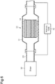
- the honeycomb filter 10 is placed in a metal pipe in an airtight state with air flowing in the honeycomb filter 10 through the metal pipe. Then, a pressure difference ⁇ P between the front and the rear of the honeycomb filter 10 is measured.
- the pressure difference ⁇ P is measured at twenty locations while changing a flow rate Q of air flowing into the honeycomb filter 10 in a range of 0 to 80 L/min with a known mass flowmeter.
- the obtained data on the twenty locations is plotted on a graph with a horizontal axis representing Q and a vertical axis representing ⁇ P/Q.
- the gas permeability coefficient is obtained from an intercept of a straight line that connects the plots.
- the partition walls 12 include linear pores that extend through the wall portion 12 and have a diameter of 1 ⁇ m or greater and 200 ⁇ m or less.
- the linear pores that extend through the partition walls 12 can be recognized by observing a cutaway surface of the partition walls 12 with an electronic microscope.
- 80% or greater of the pores having a diameter of 1 ⁇ m or greater and 200 ⁇ m or less observed with the electronic microscope are linear pores that extend through the partition walls 12.
- the linear pores may each have the form of any of a straight line, a curved line, or a bent line.
- the porosity of the partition walls 12 is not particularly limited but is preferably 40% to 80% and further preferably 55% to 75%.
- the porosity of the seal portion 14 is not particularly limited but is preferably 40% to 80% and further preferably 55% to 75%.
- the porosity of the partition walls 12 can be measured through mercury porosimetry under the condition that a contact angle is 130° and a surface tension is 485 mN/m.
- the honeycomb filter 10 is manufactured by sequentially performing a mixing process, a molding process, a sealing process, a degreasing process, a firing process, and a supporting process as described below.
- the mixing process is a process for preparing a raw material mixture by mixing raw materials such as CZ composite oxide particles, an inorganic binder, alumina particles, and organic fibers.
- a solid solution of ceria and zirconia is used as the CZ composite oxide particles.
- the solid solution of ceria and zirconium can be prepared, for example, by adding ammonia water to a water solution of a cerium salt, such as cerium nitrate, and zirconium salt, such as zirconium oxynitrate, to generate coprecipitate.
- the obtained precipitate is dried and then fired at 400°C to 500°C for approximately 5 hours.
- the average particle size of CZ composite oxide particles which is one of the raw materials, is not particularly limited. However, the average particle size is preferably 1 to 10 ⁇ m and further preferably 1 to 5 ⁇ m.
- the average particle size can be measured with a particle size distribution measurement device of a laser diffraction type.
- the ratio of the inorganic binder in the raw material mixture is not particularly limited. However, the ratio is preferably 10% to 30% by mass as a solid content.
- the ⁇ -alumina particles or the ⁇ -alumina particles can be used as the alumina particles.
- the ratio of the alumina particles in the raw material mixture is not particularly limited. However, the ratio is preferably 10% to 50% by mass as a solid content.
- the average particle size of the alumina particles is not particularly limited. However, the average particle size is preferably 1 to 10 ⁇ m and further preferably 1 to 5 ⁇ m as secondary particles.
- acrylic fibers or polyester fibers can be used as the organic fibers.
- the dimension of the organic fiber is not particularly limited, but the diameter is preferably 1 to 50 ⁇ m and further preferably 3 to 40 ⁇ m.
- the organic fiber preferably has a length of 0.1 to 30 mm and further preferably 0.1 to 10 mm.
- the ratio of the organic fibers in the raw material mixture is not particularly limited. However, the ratio is preferably 10% to 50% by mass as a solid content.
- the above raw material mixture may include the above-described low thermal expansion coefficient particles, inorganic fibers, an organic binder, a pore-forming agent, a molding aid, or a dispersion medium when necessary.
- the average particle size of the low thermal expansion coefficient particles is not particularly limited. However, the average particle size is preferably 1 to 10 ⁇ m and further preferably 1 to 5 ⁇ m.
- Examples of the material forming the inorganic fibers include alumina, silica, silica alumina, and a glass.
- organic binder examples include methyl cellulose, carboxymethyl cellulose, hydroxyethyl cellulose, polyethylene glycol, phenol resin, and epoxy resin.
- the pore-forming agent may be granular, unlike the organic fibers, and examples of such a pore-forming agent includes acrylic resin, coke, and starch.
- molding aid examples include ethylene glycol, dextrin, fatty acid, fatty acid soap, polyalcohol, and a surfactant.
- Examples of the dispersion medium include water, an organic solvent such as benzene, and an alcohol such as methanol.
- These raw materials may be mixed with a known mixer or attritor and may further be kneaded by a kneader.
- the molding process is a process for producing a honeycomb molded body by molding the raw material mixture obtained by the mixing process.
- the raw material mixture is extruded using an extrusion mold and cut into a predetermined length so that the honeycomb molded body has the same form as the honeycomb filter 10 after firing and shrinking is performed in the subsequent firing process. That is, the wall portion 13, which forms the circumferential wall 11 and the partition walls 12 of the honeycomb filter 10, are simultaneously produced through extrusion molding.
- the sealing process is a process for forming the seal portion 14 by filling the ends of the cells S of the honeycomb molded body obtained through the molding process with a sealing material paste.
- the materials that are the same as the raw material mixture may be used as the sealing material paste. However, it is preferred that organic fibers not be included in the sealing material paste. When organic fibers are not included in the sealing material paste, the porosity of the seal portion 14 can be decreased.
- the honeycomb molded body of which the seal portion 14 is formed by the sealing process is dried when necessary.
- the sealing process may be performed subsequent to a degreasing process or a firing process, which will be described below.
- the degreasing process is a process for producing a degreased body by degreasing the honeycomb molded body that has the seal portion 14.
- the degreasing process is a process for removing the organic content from the honeycomb molded body by heating the honeycomb molded body.
- the elongated organic fibers are removed through the degreasing process so that linear pores can be formed in the wall portion 13.
- the degreasing process may be performed using a known single furnace, such as a batch furnace, or a continuous furnace.
- the degreasing temperature is not particularly limited. However, the temperature is preferably 300°C to 800°C and further preferably 400°C to 750°C.
- the degreasing time is not particularly limited. However, the degreasing is preferably continued for 1 to 10 hours and further preferably 2 to 5 hours at the above-described degreasing temperature.
- the degreasing environment is not particularly limited, but it is preferred that oxygen concentration be 0.1%
- the firing process is a process for producing the honeycomb filter 10 by firing the degreased body obtained through the degreasing process.
- the firing bonds the particles of, for example, CZ composite oxide with the inorganic binder to increase the mechanical strength of the honeycomb filter 10.
- the firing process may be performed using a known single furnace, such as a batch furnace, or a continuous furnace.
- the firing temperature is not particularly limited. However, the temperature is preferably 800°C to 1300°C and further preferably 900°C to 1200°C.
- the firing time is not particularly limited. However, the firing is preferably continued for 1 to 20 hours and further preferably 1 to 15 hours at the above-described firing temperature.
- the firing environment is not particularly limited, but it is preferred that oxygen concentration be 1% to 20%.
- the firing process may be performed in a furnace that differs from the one used for the degreasing process, or may be performed successively in the same furnace as the degreasing process.
- the honeycomb filter 10 of the present embodiment is produced including the wall portion 13 that has the specified pore diameter distribution and is formed of CZ composite oxide.
- the supporting process is a process for supporting a catalyst in the honeycomb filter 10, which is obtained through the firing process.
- the catalyst may be supported, for example, through a process in which the honeycomb filter 10 is immersed in a solution including catalyst particles or complexes and pulled out of the solution to be heated.
- the wall portion 13 of the honeycomb filter 10 includes a base material containing CZ composite oxide and a catalyst supported by the base material.
- the second manufacturing method differs from the first manufacturing method in that the organic fibers are removed from the raw material and a pore forming process is included instead.
- the pore forming process will be described below.
- the pore forming process is performed subsequent to any one of the molding process, degreasing process, or firing process.
- the specific steps of the pore forming process are the same regardless of the above-mentioned timings at which the pore forming process is performed.
- the pore forming process described below is performed subsequent to the molding process.
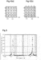
- each jig 20 includes a base 21, which extends along part (half circumference) of the outer circumferential surface of the honeycomb molded body 10A, and a plurality of needles 22, which project from the base 21.
- the two jigs 20 hold the honeycomb molded body 10A from two opposite sides in a radial direction of the honeycomb molded body 10A.
- the two jigs 20 sandwich the honeycomb molded body 10A from two opposite sides in a thickness-wise direction of the vertical walls 12A.
- the needles 22 pierce and extend through each vertical wall 12A, and then the jigs 20 are removed from the honeycomb molded body 10A. This forms the pores that extend through the vertical walls 12A of the partition walls 12 of the honeycomb molded body 10A in the thickness-wise direction the vertical walls 12A.
- pores may also be formed extending through the lateral walls 12B of the partition walls 12 in a thickness-wise direction of the lateral walls 12B by performing the operation sandwiching the honeycomb molded body 10A with the two jigs 20 from two opposite sides in the thickness-wise direction of the lateral walls 12B of the partition walls 12.
- the diameter of the needles 22 of the jig 20 is set to 50 to 200 ⁇ m. Accordingly, the diameter of the pores extending through the partition walls 12 formed by the needles 22 is also 50 to 200 ⁇ m. Since the honeycomb molded body 10A contracts during the firing process, the pores of the honeycomb filter 10 will be formed, for example, having has a diameter of 40 to 190 ⁇ m subsequent to the contraction. When the pore forming process is performed on the honeycomb filter 10, the pores are formed based on the diameter of the needles 22 so that the diameter of the pores will be 50 to 200 ⁇ m. The diameter of the formed pores can be adjusted by selecting the diameter of the needles 22. The needles 22 may have the same diameter or different diameters in the above-mentioned range. The diameter of the pores can be measured by observing the surface of the partition walls 12 with an electronic microscope.
- the number of the pores formed by the present process is not particularly limited.
- the surface of the partition walls 12 preferably includes 1 pore per 0.25 to 10 mm 2 .
- the needles 22 of the jig 20 may be changed in number or position. For example, as shown in Fig. 3(c) , when interval L between the needles 22 is set to approximately 1 cm and the direction in which the needles 22 are lined is matched with the direction in which the cells S extend, the pores can be formed at intervals of approximately 1 cm in the direction in which the cells S extend.
- the raw material mixture was used to mold a cylindrical molded body with an extrusion apparatus.
- the molded body was cut into a predetermined length to produce a honeycomb molded body, and the ends of predetermined cells of the honeycomb molded body were sealed with a sealing agent to form seal portions as shown in Fig. 2 .
- the composition of the sealing agent was the same as the above raw materials except that the organic fibers were not included. Further, the length of each seal portion was set to approximately 3 mm.
- the honeycomb molded body was degreased at 700°C for 3 hours and fired at 1100°C for 10 hours to produce a honeycomb filter.
- dinitrodiammine palladium nitrate solution [Pd (NH 3 ) 2 (NO 2 ) 2 ] HNO 3 , palladium concentration 100g/L
- rhodium nitrate solution [Rd (NO 3 ) 3 ], rhodium concentration 50g/L) were mixed at a volume ratio of 3:1 to prepare a mixed solution.
- the honeycomb filter produced through the above processes was immersed and held in the mixed solution for 15 minutes. Then, the honeycomb filter was dried at 110°C for 2 hours and fired in a nitrogen atmosphere at 500°C for 1 hour to support a palladium catalyst and a rhodium catalyst in the honeycomb filter.
- the supported amount of the catalyst was 0.14 g/L in the total of palladium and rhodium per apparent volume of the honeycomb filter.
- the obtained honeycomb filter was cylindrical and had a diameter of 117 mm, a length of 80 mm, a cell density of 46/cm 2 (300 cpsi), and a wall portion thickness of 0.254 mm (10 mil).
- the raw material mixture was used to mold a cylindrical molded body with an extrusion apparatus.
- the molded body was cut into a predetermined length to produce a honeycomb molded body, and the ends of predetermined cells of the honeycomb molded body were sealed with a sealing agent to form seal portions as shown in Fig. 2 .
- the composition of the sealing agent was the same as the above raw materials except that the organic fibers were not included. Further, the length of each seal portion was set to approximately 3 mm.
- a pair of jigs including a plurality of needles having the diameter of 100 ⁇ m were used to sandwich the honeycomb molded body from two opposite sides in the radial direction of the honeycomb molded body and the needles were inserted through the wall portion.
- the interval between the needles in a longitudinal direction of the honeycomb molded body was 1 cm and the needles were inserted in a direction that intersects each cell at 90 degrees.
- honeycomb molded body After being dried, the honeycomb molded body was degreased at 700°C for 3 hours and fired at 1100°C for 10 hours to produce a honeycomb filter.
- a catalyst was supported on the obtained honeycomb filter by the same process as Example 1.
- the obtained honeycomb filter was cylindrical and had a diameter of 117 mm, a length of 80 mm, a cell density of 46/cm 2 (300 cpsi), and a wall portion thickness of 0.254 mm (10 mil).
- the honeycomb filter of Comparative Example 1 was produced through the same procedure as Example 1 and with the same mixing ratio although the organic fibers were removed from the raw material.
- the raw material mixture was used to mold a polygonal column-shaped molded body with an extrusion apparatus.
- the molded body was cut to produce a honeycomb molded body, and the cells in the honeycomb molded body were alternately sealed with a sealing agent having the same composition as the above raw material mixture.
- the honeycomb molded body was heated at 450°C for 5 hours in a state in which the honeycomb molded body was placed on a support member, which was a cut-out piece obtained when cutting the honeycomb molded body, to remove the organic content and obtain a degreased body.
- the degreased body was preserved in an argon atmosphere at 2000°C for 4.5 hours in a state placed on the support member to obtain a honeycomb fired body.
- the honeycomb fired body was preserved in a nitrogen atmosphere having the nitrogen partial pressure of 10 kPa at 800°C for 4.5 hours to perform a nitriding process and obtain a honeycomb structure of which the main component was silicon carbide and of which dimensions was 34.4 mm x 34.3 mm x 80 mm, cell density was 46.5 cells/cm 2 (300 cpsi), and thickness was 0.254 mm.
- the obtained honeycomb structure had an average pore diameter of 20 ⁇ m and a porosity of 60%.
- This honeycomb structure was bonded by an inorganic adhesive to form an outer circumference and obtain a cylindrical honeycomb structure having a diameter of 117 mm and a length of 80 mm.
- the ⁇ -alumina particles, which support palladium, and the CZ composite oxide particles, which support rhodium, were mixed at a ratio of 1:2 and the cylindrical honeycomb structure was wash-coated to produce a honeycomb filter.
- the supported amount of the catalyst was set to 0.14 g/L in the total of palladium and rhodium per apparent volume of the honeycomb filter.
- honeycomb filters of the examples and comparative examples were measured through the processes described below.
- each honeycomb filter of Examples 1 and 2 and Comparative Example 1 was used to measure the gas permeability coefficient.
- each honeycomb filter was arranged in a metal pipe in an airtight state with air flowing in the honeycomb filter through the metal pipe.
- the pressure difference ⁇ P between the front and the rear of the honeycomb filter 10 was measured.
- the pressure difference ⁇ P was measured at twenty locations while changing the flow rate Q of air flowing into the honeycomb filter 10 in a range of 0 to 80 L/min with a known mass flowmeter.
- the obtained data on the twenty locations was plotted on a graph with a horizontal axis representing Q and a vertical axis representing ⁇ P/Q.
- the gas permeability coefficient was obtained from an intercept of a straight line that connects the plots. The results are shown in Table 1.
- Table 1 Example 1 Example 2 Comparative Example 1 Gas Permeability 1.5 2.8 0.1 Coefficient ( ⁇ m 2 )
- Each honeycomb filter of Examples 1 and 2 and Comparative Examples 1 and 2 was arranged in a metal pipe in an airtight state and connected to an exhaust pipe of a V-type 3.5 L engine with six cylinders. Then, the time required from a stoichiometric engine start for the HC concentration ((HC flow-in rate - HC flow-out rate)/(HC flow-in rate) x 100) to become 50% or less was measured to evaluate the warm-up performance.
- Fig. 6 is a schematic cross-sectional view illustrating the pressure loss measurement process.
- the honeycomb filter 10 was placed inside a metal pipe 31 in an airtight state.
- the metal pipe 31 was connected to a metal pipe 33 attached to a blower 32.
- the blower 32 forced air at a velocity of 10 m/s through the honeycomb filter 10 to measure the difference in pressure (pressure loss) between the front and the rear of the honeycomb filter 10 with a pressure gauge 34.
- the results in Tables 1 and 2 show that the honeycomb filters of Examples 1 and 2 had the gas permeability coefficient of 1.5 ⁇ m 2 and 2.8 ⁇ m 2 , respectively. Further, the wall portions were formed from ceria-zirconia composite oxide. Thus, the honeycomb filters of Examples 1 and 2 have superior warm-up performance (time required for hydrocarbon (HC) purification rate to reach 50% is relatively short) and the pressure loss is relatively low. In contrast, the honeycomb filter of Comparative Example 1 had the low gas permeability coefficient of 0.1 ⁇ m 2 . Thus, the honeycomb filter of Comparative Example 1 does not allow a gas to efficiently diffuse in the interior of the wall portion and has inferior warm-up performance and relatively high pressure loss. The honeycomb filter of Comparative Example 2 includes SiC base material and thus the warm-up performance is inferior.
- honeycomb filter 11) circumferential wall, 12) partition wall, 13) wall portion, 14) seal portion, S) cell.
Abstract
Description
- The present invention relates to a honeycomb filter used to collect fine particles.
-
Patent Document 1 discloses a honeycomb filter that is formed from silicon carbide and used to collect fine particles.Patent Document 2 discloses an exhaust gas purification catalyst in which a noble metal is supported by a monolith base material including ceria-zirconia composite oxide particles. The ceria-zirconia composite oxide particles, which form the base material, reduce the thermal capacity of the base material so that the temperature of the monolith base material can easily be increased. This improves the warm-up performance of the catalyst. -
- Patent Document 1: International Patent Publication No.
2006/041174 - Patent Document 2: Japanese Laid-Open Patent Publication No.
2015-85241 - In order to improve the warm-up performance of the honeycomb filter disclosed in
Patent Document 1, the base material including ceria-zirconia composite oxide particles disclosed inPatent Document 2 could be employed as a wall portion of the honeycomb filter. However, the base material including ceria-zirconia composite oxide particles disclosed inPatent Document 2 is not suitable for the wall portion of the honeycomb filter for collecting fine particles because the wall portion does not allow the passage of gas including fine particles. The recrystallization of silicon carbide particles form pores between particles. However, ceria-zirconia composite oxide particles are bonded by an inorganic binder. Thus, suitable-sized pores for the passage of gas cannot be formed between particles. Further, the wall portion formed from a base material of, for example, silicon carbide can be coated by ceria-zirconia composite oxide. However, in this case, the supported amount of ceria-zirconia composite oxide will be limited to a range that can be coated on the wall portion. This will adversely affect the exhaust gas purification performance. Moreover, a structure coating the base material will increase the weight of the honeycomb filter thereby lowering the warm-up performance. Accordingly, it is an objective of the present invention to provide a honeycomb filter that has superior warm-up performance. - A honeycomb filter that solves the above problem is to be used for collecting fine particles and includes a wall portion formed from a base material containing ceria-zirconia composite oxide and an inorganic binder. The wall portion has a gas permeability coefficient of 1.0 µm2 or greater and 3.0 µm2 or less.
- With this structure, the honeycomb filter includes the wall portion formed from the base material containing ceria-zirconia composite oxide. Thus, as long as the contents of ceria-zirconia composite oxide are the same, the thermal capacity of the wall portion is smaller than when coating the wall portion, which is formed from a base material of, for example, silicon carbide, with ceria-zirconia composite oxide. Accordingly, the temperature of the honeycomb filter is easily increased by the heat of the gas subject to treatment. This improves the warm-up performance of the honeycomb filter. Further, the gas permeability coefficient of 1.0 µm2 or greater and 3.0 µm2 or less improves the gas permeability of the wall portion formed from the base material containing ceria-zirconia composite oxide. This keeps the pressure loss low while maintaining functionality as a filter that collects fine particles. Further, the gas subject to treatment can penetrate to the interior of the wall portion of the honeycomb filter thereby improving the gas purification performance. Here, "warm-up performance" indicates how easily the temperature of the honeycomb filter is increased to obtain a suitable purification performance. Thus, when a honeycomb filter has a small weight per unit volume and a high purification performance like the honeycomb filter of the present invention, "warm-up performance" will be satisfactory.
- In the honeycomb filter of the present invention, it is preferred that the wall portion include linear pores that extend through the wall portion and have a diameter of 1 µm or greater and 200 µm or less. With this structure, the gas easily passes through the wall portion through the pores extending through the wall portion. This increases the gas permeability of the wall portion.
- It is preferred that the base material of the honeycomb filter of the present invention contains alumina as a component. With this structure, the base material contains alumina as a component so that a catalyst is thoroughly dispersed when supported by the base material. This improves the performance for purifying the gas subject to treatment. Further, the mechanical strength of the wall portion under a high temperature is increased.
- In the honeycomb filter of the present invention, it is preferred that a catalyst be supported by the base material. With this structure, the honeycomb filter has the functions for collecting fine particles as well as a catalyst-based function such as the effect for purifying the gas subject to treatment. Further, the superior warm-up performance of the wall portion allows for prompt increase in the temperature of the wall portion to a suitable temperature for the catalyst.
- In the honeycomb filter of the present invention, it is preferred that the catalyst be a noble metal. The ceria-zirconia composite oxide functions as an auxiliary catalyst that enhances the catalysis effect of a catalyst formed of a noble metal. Thus, the honeycomb filter of the present invention provides a high catalyst effect when combined with a catalyst formed of a noble metal.
- It is preferred that the honeycomb filter of the present invention be partitioned by the wall portion and include a plurality of cells that extend from a first end, which is located at one end side of the honeycomb filter, to a second end, which is located at the other end side of the honeycomb filter. It is preferred that the cells include a first cell, second cell, and third cell. The first cell has an open end located at the first end and a sealed end located at the second end. The second cell is adjacent to the first cell and has a sealed end located at the first end and an open end located at the second end. The third cell is adjacent to at least one of the first cell and the second cell and has open ends located at both the first end and the second end. With this structure, fine particles can be collected in the wall portion between the first cells and the second cells. Further, the third cells, which has open ends located at both the first end and the second end, decrease the pressure loss of the honeycomb filter.
- The present invention succeeds in providing a honeycomb filter that has superior warm-up performance.
-
-
Fig. 1 is a perspective view of a honeycomb filter. -
Fig. 2 is a cross-sectional view taken along line 2-2 inFig. 1 . -
Fig. 3(a) is a perspective view of a jig that forms pores in the honeycomb filter. -
Fig. 3(b) is a front view of the jig that forms pores in the honeycomb filter. -
Fig. 3(c) illustrates the pores formed in the honeycomb filter by the jig. -
Fig. 4(a) and Fig. 4(b) are diagrams schematically showing needle-insertion directions. -
Fig. 5 is a graph showing the pore diameter distribution of a wall portion in an example. -
Fig. 6 is a schematic diagram of a pressure loss measuring device. - One embodiment of the present invention will now be described.
- As shown in
Fig. 1 , ahoneycomb filter 10 of the present embodiment includes a cylindricalcircumferential wall 11 and partition walls 12 forming a honeycomb-shaped cross-section and partitioning the inside of thecircumferential wall 11 into a plurality of cells S. Each cell S extends from one axial end side to the other axial end side of thecircumferential wall 11, that is, each cell S extends from a first end, which is located at one end side of thehoneycomb filter 10, to a second end, which is located at the other end side of thehoneycomb filter 10. Thecircumferential wall 11 and the partition walls 12 form awall portion 13. The cell structure of thehoneycomb filter 10 is not particularly limited. For example, the partition walls 12 may have a thickness of 0.1 to 0.7 mm and a cell density of 15.5 to 124 cells per 1 cm2. Here, "0.1 to 0.7 mm" means "greater than or equal to 0.1 mm and less than or equal to 0.7 mm", and "15.5 to 124 cells" means " greater than or equal to 15.5 cells and less than or equal to 124 cells". That is, in the present specification, "A to B" refers to "greater than or equal to A and less than or equal to B". - The
wall portion 13 is formed from a base material containing ceria-zirconia composite oxide (hereafter, may also be referred to as "CZ composite oxide"), an inorganic binder, and alumina. That is, the base material forming thewall portion 13 includes CZ composite oxide, an inorganic binder, and alumina. A catalyst is supported on surfaces of the particles that form the base material. - The CZ composite oxide forming the base material of the honeycomb filter of the present invention preferably includes 10% by mass or greater of ceria and further preferably 20% by mass or greater of ceria. Moreover, the CZ composite oxide forming the base material of the honeycomb filter of the present invention preferably includes 70% by mass or less of ceria and further preferably 60% by mass or less of ceria. When 10% by mass or greater of ceria is included, the capacity for storing and releasing the oxygen included in the exhaust gas will be increased. Also, when 70% by mass or less of ceria is included, the thermal durability of the honeycomb filter will be increased.
- The CZ composite oxide may further include an element selected from rare earth elements excluding cerium. Examples of rare earth elements excluding cerium include scandium (Sc), yttrium (Y), lanthanum (La), praseodymium (Pr), neodymium (Nd), samarium (Sm), gadolinium (Gd), terbium (Tb), dysprosium (Dy), ytterbium (Yb), and lutetium (Lu).
- The content of CZ composite oxide in the base material is preferably 15% to 60% by mass.
- For example, alumina sol, silica sol, titania sol, liquid glass, sepiolite, attapulgite, bentonite, or boehmite may be used as the inorganic binder. The content of the inorganic binder in the base material is not particularly limited. However, the base material preferably includes 10% to 30% by mass of the inorganic binder.
- Preferably, alumina particles are included as the above-mentioned alumina. When the alumina particles are included, for example, a noble metal used as the catalyst will be easily dispersed and supported. Further, the alumina particles increase the mechanical strength of the
wall portion 13. The type of the alumina particles is not particularly limited. However, it is preferred that alumina of θ phase (hereafter, also referred to as "θ-alumina") or alumina of γ phase (hereafter, also referred to as "γ-alumina") be used. The θ-alumina limits phase transition even when exposed to a high temperature of approximately 1000°C. Thus, using the θ-alumina as a component of the base material will increase the mechanical strength of thehoneycomb filter 10 under a high temperature. The γ-alumina has a large specific surface area so that a noble metal used as the catalyst can be thoroughly dispersed. The content of alumina particles in the base material is not particularly limited. However, the base material preferably includes 15% to 60% by mass of alumina particles. - The base material may include another component in addition to CZ composite oxide, an inorganic binder, and alumina. The other component may be, for example, other inorganic particles having a coefficient of thermal expansion smaller than that of CZ composite oxide and alumina (hereafter, also referred to as "low thermal expansion coefficient particles").
- The low thermal expansion coefficient particles included as the other component can lower the coefficient of thermal expansion of the base material. This increases the thermal shock resistance of the
honeycomb filter 10. Examples of the low thermal expansion coefficient particles include particles of cordierite, aluminum titanate, and lithium aluminosilicate materials. Examples of lithium aluminosilicate materials include β-spodumene and β-eucryptite. The content of the low thermal expansion coefficient particles is not particularly limited, but the base material preferably includes 5% to 30% by mass of the low thermal expansion coefficient particles. - The catalyst supported by the base material may be a noble metal, an alkali metal (
group 1 in periodic table of elements), an alkaline earth metal (group 2 in periodic table of elements), a rare earth element (group 3 in periodic table of elements), or a transition metal element. The catalyst supported by the base material is preferably a noble metal. The noble metal may be, for example, a platinum group metal, such as platinum, palladium, and rhodium. The supported amount of the noble metal is not particularly limited, but it is preferred to support 0.1 to 20 g/L and further preferably 0.5 to 15 g/L of the noble metal relative to the apparent volume (L) of thehoneycomb filter 10. - As shown in
Fig. 2 , predetermined ones of the cells S each have an end sealed by aseal portion 14. That is, thehoneycomb filter 10 includes first cells S1, each of which has an open end located at the first end (one end side) of thehoneycomb filter 10 and a sealed end located at the second end (the other end side), and second cells S2, each of which is adjacent to the first cell S1, and has a sealed end located at the first end and an open end located at the second end. The sealed ends of the first cells S1 are located at sides that differ from that of the sealed ends of the second cells S2. Thus, as shown by the arrows inFig. 2 , the gas flowing into the first cells S1 at one end side of thehoneycomb filter 10 passes through the interior of thewall portion 13 between the first cells S1 and the second cells S2 and flows into the second cells S2. Then, the gas flows out of thehoneycomb filter 10 at the other end side of thehoneycomb filter 10. Here, fine particles included in the gas are collected in the surfaces of thewall portion 13 in the first cells S1. - The
honeycomb filter 10 may further include third cells S3, each of which is adjacent to at least one of a first cell S1 and a second cell S2 and each of which has two open ends located at both one end side and the other end side of thehoneycomb filter 10. That is, some of the cells S may have two open ends. The gas flowing into each cell S3 at one end side of thehoneycomb filter 10 passes through the third cell S3 and flows out of thehoneycomb filter 10 at the other end side of thehoneycomb filter 10. If the third cell S3 is adjacent to a first cell S1, the gas flowing into the first cell S1 at one end side of thehoneycomb filter 10 may pass through the interior of thewall portion 13 between the first cell S1 and the third cell S3 and flow into the third cell S3 and then out of thehoneycomb filter 10 at the other end side of thehoneycomb filter 10. - Each third cell S3 is located at a position selected from a range that is adjacent to at least one of a first cell S1 and a second cell S2. For example, as shown in
Fig. 2 , the third cell S3 may be the cell S having a relatively small cross-sectional area and located close to the outer circumference of thehoneycomb filter 10. Further, the ratio of the number of the third cells S3 to the total number of the cells S is not particularly limited but is preferably 1/3 or less. - Length T of the
seal portion 14 shown inFig. 2 is not particularly limited. However, the length T is preferably greater than the thickness of the partition walls 12. When the thickness of the partition walls 12 is 0.1 to 0.7 mm, the length T of theseal portion 14 is preferably 1 to 10 mm. - The pore structure related to the gas permeability of the
wall portion 13 of thehoneycomb filter 10 will now be described. - The
honeycomb filter 10 of the present embodiment is used to collect fine particles included in the exhaust gas from an internal combustion engine of, for example, a vehicle or a construction machine. Accordingly, the partition walls 12 of thehoneycomb filter 10 include pores so that the gas subject to treatment passes through the partition walls 12. The partition walls 12 are a wall portion that has a specified gas permeability coefficient of 1.0 µm2 or greater and 3.0 µm2 or less. The gas permeability coefficient of 1.0 µm2 or greater increases the gas permeability of the partition walls 12. The gas permeability coefficient of 3.0 µm2 or less increases the collecting efficiency when using thehoneycomb filter 10 as a filter for collecting fine particles. The gas permeability coefficient can be measured by the process described below by a following method using a known mass flowmeter. - First, the
honeycomb filter 10 is placed in a metal pipe in an airtight state with air flowing in thehoneycomb filter 10 through the metal pipe. Then, a pressure difference ΔP between the front and the rear of thehoneycomb filter 10 is measured. The pressure difference ΔP is measured at twenty locations while changing a flow rate Q of air flowing into thehoneycomb filter 10 in a range of 0 to 80 L/min with a known mass flowmeter. The obtained data on the twenty locations is plotted on a graph with a horizontal axis representing Q and a vertical axis representing ΔP/Q. The gas permeability coefficient is obtained from an intercept of a straight line that connects the plots. - The partition walls 12 include linear pores that extend through the wall portion 12 and have a diameter of 1 µm or greater and 200 µm or less. The linear pores that extend through the partition walls 12 can be recognized by observing a cutaway surface of the partition walls 12 with an electronic microscope. Preferably, 80% or greater of the pores having a diameter of 1 µm or greater and 200 µm or less observed with the electronic microscope are linear pores that extend through the partition walls 12. The linear pores may each have the form of any of a straight line, a curved line, or a bent line.
- The porosity of the partition walls 12 is not particularly limited but is preferably 40% to 80% and further preferably 55% to 75%. The porosity of the
seal portion 14 is not particularly limited but is preferably 40% to 80% and further preferably 55% to 75%. The porosity of the partition walls 12 can be measured through mercury porosimetry under the condition that a contact angle is 130° and a surface tension is 485 mN/m. - A first method for manufacturing the
honeycomb filter 10 of the present embodiment will now be described. In the first manufacturing method, thehoneycomb filter 10 is manufactured by sequentially performing a mixing process, a molding process, a sealing process, a degreasing process, a firing process, and a supporting process as described below. - The mixing process is a process for preparing a raw material mixture by mixing raw materials such as CZ composite oxide particles, an inorganic binder, alumina particles, and organic fibers. Preferably, a solid solution of ceria and zirconia is used as the CZ composite oxide particles. The solid solution of ceria and zirconium can be prepared, for example, by adding ammonia water to a water solution of a cerium salt, such as cerium nitrate, and zirconium salt, such as zirconium oxynitrate, to generate coprecipitate. The obtained precipitate is dried and then fired at 400°C to 500°C for approximately 5 hours.
- The average particle size of CZ composite oxide particles, which is one of the raw materials, is not particularly limited. However, the average particle size is preferably 1 to 10 µm and further preferably 1 to 5 µm. The average particle size can be measured with a particle size distribution measurement device of a laser diffraction type.
- Any of the above examples of an inorganic binder may be used as the inorganic binder. The ratio of the inorganic binder in the raw material mixture is not particularly limited. However, the ratio is preferably 10% to 30% by mass as a solid content.
- As described above, the θ-alumina particles or the γ-alumina particles can be used as the alumina particles. The ratio of the alumina particles in the raw material mixture is not particularly limited. However, the ratio is preferably 10% to 50% by mass as a solid content. The average particle size of the alumina particles is not particularly limited. However, the average particle size is preferably 1 to 10 µm and further preferably 1 to 5 µm as secondary particles.
- For example, acrylic fibers or polyester fibers can be used as the organic fibers. The dimension of the organic fiber is not particularly limited, but the diameter is preferably 1 to 50 µm and further preferably 3 to 40 µm. Moreover, the organic fiber preferably has a length of 0.1 to 30 mm and further preferably 0.1 to 10 mm. The ratio of the organic fibers in the raw material mixture is not particularly limited. However, the ratio is preferably 10% to 50% by mass as a solid content.
- The above raw material mixture may include the above-described low thermal expansion coefficient particles, inorganic fibers, an organic binder, a pore-forming agent, a molding aid, or a dispersion medium when necessary.
- The average particle size of the low thermal expansion coefficient particles is not particularly limited. However, the average particle size is preferably 1 to 10 µm and further preferably 1 to 5 µm.
- Examples of the material forming the inorganic fibers include alumina, silica, silica alumina, and a glass.
- Examples of the organic binder include methyl cellulose, carboxymethyl cellulose, hydroxyethyl cellulose, polyethylene glycol, phenol resin, and epoxy resin.
- The pore-forming agent may be granular, unlike the organic fibers, and examples of such a pore-forming agent includes acrylic resin, coke, and starch.
- Examples of the molding aid include ethylene glycol, dextrin, fatty acid, fatty acid soap, polyalcohol, and a surfactant.
- Examples of the dispersion medium include water, an organic solvent such as benzene, and an alcohol such as methanol.
- These raw materials may be mixed with a known mixer or attritor and may further be kneaded by a kneader.
- The molding process is a process for producing a honeycomb molded body by molding the raw material mixture obtained by the mixing process. For example, the raw material mixture is extruded using an extrusion mold and cut into a predetermined length so that the honeycomb molded body has the same form as the
honeycomb filter 10 after firing and shrinking is performed in the subsequent firing process. That is, thewall portion 13, which forms thecircumferential wall 11 and the partition walls 12 of thehoneycomb filter 10, are simultaneously produced through extrusion molding. - The sealing process is a process for forming the
seal portion 14 by filling the ends of the cells S of the honeycomb molded body obtained through the molding process with a sealing material paste. The materials that are the same as the raw material mixture may be used as the sealing material paste. However, it is preferred that organic fibers not be included in the sealing material paste. When organic fibers are not included in the sealing material paste, the porosity of theseal portion 14 can be decreased. The honeycomb molded body of which theseal portion 14 is formed by the sealing process is dried when necessary. The sealing process may be performed subsequent to a degreasing process or a firing process, which will be described below. - The degreasing process is a process for producing a degreased body by degreasing the honeycomb molded body that has the
seal portion 14. In other words, the degreasing process is a process for removing the organic content from the honeycomb molded body by heating the honeycomb molded body. The elongated organic fibers are removed through the degreasing process so that linear pores can be formed in thewall portion 13. The degreasing process may be performed using a known single furnace, such as a batch furnace, or a continuous furnace. The degreasing temperature is not particularly limited. However, the temperature is preferably 300°C to 800°C and further preferably 400°C to 750°C. The degreasing time is not particularly limited. However, the degreasing is preferably continued for 1 to 10 hours and further preferably 2 to 5 hours at the above-described degreasing temperature. The degreasing environment is not particularly limited, but it is preferred that oxygen concentration be 0.1% to 20%. - The firing process is a process for producing the
honeycomb filter 10 by firing the degreased body obtained through the degreasing process. The firing bonds the particles of, for example, CZ composite oxide with the inorganic binder to increase the mechanical strength of thehoneycomb filter 10. The firing process may be performed using a known single furnace, such as a batch furnace, or a continuous furnace. The firing temperature is not particularly limited. However, the temperature is preferably 800°C to 1300°C and further preferably 900°C to 1200°C. The firing time is not particularly limited. However, the firing is preferably continued for 1 to 20 hours and further preferably 1 to 15 hours at the above-described firing temperature. The firing environment is not particularly limited, but it is preferred that oxygen concentration be 1% to 20%. The firing process may be performed in a furnace that differs from the one used for the degreasing process, or may be performed successively in the same furnace as the degreasing process. Through the mixing process, molding process, sealing process, degreasing process, and firing process, thehoneycomb filter 10 of the present embodiment is produced including thewall portion 13 that has the specified pore diameter distribution and is formed of CZ composite oxide. - The supporting process is a process for supporting a catalyst in the
honeycomb filter 10, which is obtained through the firing process. The catalyst may be supported, for example, through a process in which thehoneycomb filter 10 is immersed in a solution including catalyst particles or complexes and pulled out of the solution to be heated. When the catalyst is supported, thewall portion 13 of thehoneycomb filter 10 includes a base material containing CZ composite oxide and a catalyst supported by the base material. - A second method for manufacturing the
honeycomb filter 10 of the present embodiment will now be described. - The second manufacturing method differs from the first manufacturing method in that the organic fibers are removed from the raw material and a pore forming process is included instead. The pore forming process will be described below.
- The pore forming process is performed subsequent to any one of the molding process, degreasing process, or firing process. The specific steps of the pore forming process are the same regardless of the above-mentioned timings at which the pore forming process is performed. As an example, the pore forming process described below is performed subsequent to the molding process.
- As shown in
Figs. 3(a) and 3(b) , in the pore forming process, a pair ofjigs 20 are used. Eachjig 20 includes abase 21, which extends along part (half circumference) of the outer circumferential surface of the honeycomb moldedbody 10A, and a plurality ofneedles 22, which project from thebase 21. The twojigs 20 hold the honeycomb moldedbody 10A from two opposite sides in a radial direction of the honeycomb moldedbody 10A. Specifically, when the partition walls 12 extending in one direction are referred to as vertical walls 12Aand the partition walls 12 intersecting thevertical walls 12A are referred to aslateral walls 12B, the twojigs 20 sandwich the honeycomb moldedbody 10A from two opposite sides in a thickness-wise direction of thevertical walls 12A. As shown inFig. 4(a) , theneedles 22 pierce and extend through eachvertical wall 12A, and then thejigs 20 are removed from the honeycomb moldedbody 10A. This forms the pores that extend through thevertical walls 12A of the partition walls 12 of the honeycomb moldedbody 10A in the thickness-wise direction thevertical walls 12A. - As shown in
Fig. 4(b) , when necessary, pores may also be formed extending through thelateral walls 12B of the partition walls 12 in a thickness-wise direction of thelateral walls 12B by performing the operation sandwiching the honeycomb moldedbody 10A with the twojigs 20 from two opposite sides in the thickness-wise direction of thelateral walls 12B of the partition walls 12. - The diameter of the
needles 22 of thejig 20 is set to 50 to 200 µm. Accordingly, the diameter of the pores extending through the partition walls 12 formed by theneedles 22 is also 50 to 200 µm. Since the honeycomb moldedbody 10A contracts during the firing process, the pores of thehoneycomb filter 10 will be formed, for example, having has a diameter of 40 to 190 µm subsequent to the contraction. When the pore forming process is performed on thehoneycomb filter 10, the pores are formed based on the diameter of theneedles 22 so that the diameter of the pores will be 50 to 200 µm. The diameter of the formed pores can be adjusted by selecting the diameter of theneedles 22. Theneedles 22 may have the same diameter or different diameters in the above-mentioned range. The diameter of the pores can be measured by observing the surface of the partition walls 12 with an electronic microscope. - The number of the pores formed by the present process is not particularly limited. However, the surface of the partition walls 12 preferably includes 1 pore per 0.25 to 10 mm2.
- Further, the
needles 22 of thejig 20 may be changed in number or position. For example, as shown inFig. 3(c) , when interval L between theneedles 22 is set to approximately 1 cm and the direction in which theneedles 22 are lined is matched with the direction in which the cells S extend, the pores can be formed at intervals of approximately 1 cm in the direction in which the cells S extend. - The operation and advantages of the present embodiment will now be described.
- (1) The honeycomb filter includes a wall portion formed from a base material containing CZ composite oxide and an inorganic binder so that the thermal capacity of the wall portion is smaller than that when the wall portion including a base material of, for example, silicon carbide is coated with CZ composite oxide as long as the contents of CZ composite oxide are the same. Thus, the temperature of the honeycomb filter is easily increased by the heat of the gas subject to treatment. This improves the purification of the gas subject to treatment. Further, the gas permeability coefficient of 1.0 µm2 or greater and 3.0 µm2 or less improves the gas permeability of the wall portion formed from the base material containing CZ composite oxide. This keeps the pressure loss low while maintaining functionality as a filter that collects fine particles.
- (2) The wall portion includes linear pores that extend through the wall portion and have a diameter of 1 µm or greater and 200 µm or less. Thus, the gas easily passes through the wall portion through the pores extending through the wall portion. This reduces the pressure loss.
- (3) The base material of the wall portion contains alumina as a component. Thus, the supported catalyst can be thoroughly dispersed. This improves the purification of the gas subject to treatment. Further, the mechanical strength of the wall portion under a high temperature is increased.
- (4) The base material of the wall portion includes a catalyst that is supported by the wall portion. Thus, the honeycomb filter performs the function of collecting fine particles as well as the catalyst-based function such as the effect for purifying the gas subject to treatment.
- (5) When the catalyst is a noble metal, the ceria-zirconia composite oxide functions as an auxiliary catalyst that enhances the catalysis effect of the catalyst formed of a noble metal. Thus, the honeycomb filter provides a high catalyst effect.
- (6) The honeycomb filter is partitioned by the wall portion and includes a plurality of cells that extend from a first end, which is located at the one end side of the honeycomb filter, to a second end, which is located at the other end side of the honeycomb filter. The cells include first cells, each of which has an open end located at the first end and a sealed end located at the second end, second cells, each of which is adjacent to the first cell and has a sealed end located at the first end and an open end located at the second end, and third cells, each of which is adjacent to at least one of a first cell and a second cell and has two open ends located at both the first end and the second end.
Thus, the wall portion between the first cells and the second cells can collect fine particles. Further, the third cells, each of which has two open ends located at both the second end and the second end, decrease the pressure loss of the honeycomb filter. - (7) The organic fibers are contained in the raw material mixture of the honeycomb filter and then removed by the degreasing process. This forms linear pores that extend through the wall portion of the honeycomb filter and have a diameter of 1 µm or greater and 50 µm or less.
- (8) In the pore forming process, a jig including a plurality of needles is used to form pores. This forms linear pores that extend through the wall portion and have a diameter of 40 µm or greater and 200 µm or less.
- The present embodiment may be modified as described below. Further, components in the above embodiment and the following modifications may be appropriately combined.
- In the present embodiment, the wall portion includes the circumferential wall and partition walls but may only include the partition walls. In this case, the honeycomb filter may be formed by forming an outer coating layer around the outer circumference of the partition walls.
- As shown in
Fig. 5 , the wall portion may have a peak in a range in which the pore diameter is greater than or equal to 0.01 µm and less than 1 µm and a peak in a range in which the pore diameter is greater than or equal to 1 µm and less than or equal to 50 µm in a pore diameter distribution in which a pore diameter and a log differential pore volume measured through mercury porosimetry are respectively represented by a horizontal axis and a vertical axis. When the wall portion has such a pore diameter distribution, the gas permeability coefficient of the wall portion is likely to be 1.0 µm2 or greater and 3.0 µm2 or less. - The honeycomb molded body may undergo the sealing process before the pore forming process. Further, when the pore forming process is performed on the honeycomb molded body, it is preferred that the honeycomb molded body be pierced with heated needles to form the pores. In this case, if the needles are heated to a temperature greater than or equal to the temperature at which volatile components such as organic components included in the honeycomb molded body are vaporized, the needles can be inserted while vaporizing the volatile components. This reduces the resistance when inserting the needles. Moreover, the honeycomb molded body does not include voids between the ceria-zirconia particles in the wall portion. This increases the strength as a base material. Thus, when inserting the needles, the pores can be formed while maintaining the shape of the wall portion in a preferred manner. The heating temperature of the needles is not particularly limited, but is preferably 200°C to 500°C.
- In the second manufacturing method including the pore forming process, the organic fibers may be included in the raw material mixture, like the first manufacturing method.
- The base material forming the wall portion does not necessarily have to contain alumina as a component. Further, the raw material of the honeycomb filter does not necessarily include alumina particles.
- The honeycomb filter does not necessarily have to include the third cells. That is, the honeycomb filter may be structured so that each cell is sealed at one of the two ends. This structure improves the collecting efficiency of the honeycomb filter.
- Examples of the above-described embodiment will now be described.
- The following raw materials were mixed to prepare a raw material mixture.
- CZ composite oxide particles with average particle diameter of 2 µm: 24.0% by mass
- θ-alumina particles with average particle diameter of 2 µm: 12.0% by mass
- α-alumina fibers (inorganic fiber) with average fiber diameter of 3 µm and average length of 60 µm: 5.0% by mass
- Acrylic fibers (organic fibers) with average fiber diameter of 30 µm and average length of 1 mm: 13.0% by mass
- Boehmite (inorganic binder): 10.0% by mass
- Methyl cellulose (organic binder): 7.0% by mass
- Polyoxyethylene oleyl ether (molding aid): 4.0% by mass
- Ion-exchanged water (dispersion medium): 25.0% by mass
- The raw material mixture was used to mold a cylindrical molded body with an extrusion apparatus. The molded body was cut into a predetermined length to produce a honeycomb molded body, and the ends of predetermined cells of the honeycomb molded body were sealed with a sealing agent to form seal portions as shown in
Fig. 2 . The composition of the sealing agent was the same as the above raw materials except that the organic fibers were not included. Further, the length of each seal portion was set to approximately 3 mm. After being dried, the honeycomb molded body was degreased at 700°C for 3 hours and fired at 1100°C for 10 hours to produce a honeycomb filter. - Subsequently, dinitrodiammine palladium nitrate solution ([Pd (NH3)2(NO2)2] HNO3, palladium concentration 100g/L) and rhodium nitrate solution ([Rd (NO3)3], rhodium concentration 50g/L) were mixed at a volume ratio of 3:1 to prepare a mixed solution. The honeycomb filter produced through the above processes was immersed and held in the mixed solution for 15 minutes. Then, the honeycomb filter was dried at 110°C for 2 hours and fired in a nitrogen atmosphere at 500°C for 1 hour to support a palladium catalyst and a rhodium catalyst in the honeycomb filter. The supported amount of the catalyst was 0.14 g/L in the total of palladium and rhodium per apparent volume of the honeycomb filter. The obtained honeycomb filter was cylindrical and had a diameter of 117 mm, a length of 80 mm, a cell density of 46/cm2 (300 cpsi), and a wall portion thickness of 0.254 mm (10 mil).
- The following raw materials were mixed to prepare a raw material mixture.
- CZ composite oxide particles with average particle diameter of 2 µm: 28.0% by mass
- θ-alumina particles with average particle diameter of 2 µm: 14.0% by mass
- α-alumina fibers (inorganic fiber) with average fiber diameter of 3 µm, average length of 60 µm: 6.0% by mass
- Boehmite (inorganic binder): 11.0% by mass
- Methyl cellulose (organic binder): 8.0% by mass
- Polyoxyethylene oleyl ether (molding aid): 5.0% by mass
- Ion-exchanged water (dispersion medium): 28.0% by mass
- The raw material mixture was used to mold a cylindrical molded body with an extrusion apparatus. The molded body was cut into a predetermined length to produce a honeycomb molded body, and the ends of predetermined cells of the honeycomb molded body were sealed with a sealing agent to form seal portions as shown in
Fig. 2 . The composition of the sealing agent was the same as the above raw materials except that the organic fibers were not included. Further, the length of each seal portion was set to approximately 3 mm. - Subsequently, a pair of jigs including a plurality of needles having the diameter of 100 µm were used to sandwich the honeycomb molded body from two opposite sides in the radial direction of the honeycomb molded body and the needles were inserted through the wall portion. The interval between the needles in a longitudinal direction of the honeycomb molded body was 1 cm and the needles were inserted in a direction that intersects each cell at 90 degrees.
- After being dried, the honeycomb molded body was degreased at 700°C for 3 hours and fired at 1100°C for 10 hours to produce a honeycomb filter. A catalyst was supported on the obtained honeycomb filter by the same process as Example 1. The obtained honeycomb filter was cylindrical and had a diameter of 117 mm, a length of 80 mm, a cell density of 46/cm2 (300 cpsi), and a wall portion thickness of 0.254 mm (10 mil).
- The honeycomb filter of Comparative Example 1 was produced through the same procedure as Example 1 and with the same mixing ratio although the organic fibers were removed from the raw material.
- First, the following raw materials were mixed to prepare a raw material mixture.
- Silicon carbide particles with average particle diameter of 15 µm: 28% by mass
- Silicon carbide particles with average particle diameter of 0.95 µm: 19% by mass
- Shirasu balloons with average particle size of 34 µm (pore-forming agent): 9% by mass
- Starch with average particle size of 28 µm (pore-forming agent): 16% by mass
- Methyl cellulose (organic binder): 5% by mass
- Sorbitan fatty acid ester (dispersant): 3% by mass
- Polyoxyalkylene compound (plasticizer): 2% by mass
- Water (dispersion medium): 18% by mass
- The raw material mixture was used to mold a polygonal column-shaped molded body with an extrusion apparatus. The molded body was cut to produce a honeycomb molded body, and the cells in the honeycomb molded body were alternately sealed with a sealing agent having the same composition as the above raw material mixture. The honeycomb molded body was heated at 450°C for 5 hours in a state in which the honeycomb molded body was placed on a support member, which was a cut-out piece obtained when cutting the honeycomb molded body, to remove the organic content and obtain a degreased body. The degreased body was preserved in an argon atmosphere at 2000°C for 4.5 hours in a state placed on the support member to obtain a honeycomb fired body. The honeycomb fired body was preserved in a nitrogen atmosphere having the nitrogen partial pressure of 10 kPa at 800°C for 4.5 hours to perform a nitriding process and obtain a honeycomb structure of which the main component was silicon carbide and of which dimensions was 34.4 mm x 34.3 mm x 80 mm, cell density was 46.5 cells/cm2 (300 cpsi), and thickness was 0.254 mm. The obtained honeycomb structure had an average pore diameter of 20 µm and a porosity of 60%. This honeycomb structure was bonded by an inorganic adhesive to form an outer circumference and obtain a cylindrical honeycomb structure having a diameter of 117 mm and a length of 80 mm.
- Subsequently, the γ-alumina particles, which support palladium, and the CZ composite oxide particles, which support rhodium, were mixed at a ratio of 1:2 and the cylindrical honeycomb structure was wash-coated to produce a honeycomb filter. In this case, the supported amount of the catalyst was set to 0.14 g/L in the total of palladium and rhodium per apparent volume of the honeycomb filter.
- The gas permeability coefficient, warm-up performance, and pressure loss of the honeycomb filters of the examples and comparative examples were measured through the processes described below.
- Each honeycomb filter of Examples 1 and 2 and Comparative Example 1 was used to measure the gas permeability coefficient. First, each honeycomb filter was arranged in a metal pipe in an airtight state with air flowing in the honeycomb filter through the metal pipe. Then, the pressure difference ΔP between the front and the rear of the
honeycomb filter 10 was measured. The pressure difference ΔP was measured at twenty locations while changing the flow rate Q of air flowing into thehoneycomb filter 10 in a range of 0 to 80 L/min with a known mass flowmeter. The obtained data on the twenty locations was plotted on a graph with a horizontal axis representing Q and a vertical axis representing ΔP/Q. The gas permeability coefficient was obtained from an intercept of a straight line that connects the plots. The results are shown in Table 1.Table 1 Example 1 Example 2 Comparative Example 1 Gas Permeability 1.5 2.8 0.1 Coefficient (µm2) - Each honeycomb filter of Examples 1 and 2 and Comparative Examples 1 and 2 was arranged in a metal pipe in an airtight state and connected to an exhaust pipe of a V-type 3.5 L engine with six cylinders. Then, the time required from a stoichiometric engine start for the HC concentration ((HC flow-in rate - HC flow-out rate)/(HC flow-in rate) x 100) to become 50% or less was measured to evaluate the warm-up performance.
- The pressure loss of the honeycomb filters of Examples 1 and 2 and Comparative Examples 1 and 2 were measured with a pressure
loss measurement device 30 shown inFig. 6. Fig. 6 is a schematic cross-sectional view illustrating the pressure loss measurement process. First, thehoneycomb filter 10 was placed inside ametal pipe 31 in an airtight state. Themetal pipe 31 was connected to ametal pipe 33 attached to ablower 32. Then, theblower 32 forced air at a velocity of 10 m/s through thehoneycomb filter 10 to measure the difference in pressure (pressure loss) between the front and the rear of thehoneycomb filter 10 with apressure gauge 34. - The results of the warm-up performance measurement and the pressure loss measurement are shown in Table 2.
Table 2 Time Required to Reach HC Purification Rate 50% (s) Pressure Loss (kPa) Example 1 12 14.8 Example 2 12 11.4 Comparative Example 1 20 52.9 Comparative Example 2 25 12.5 - The results in Tables 1 and 2 show that the honeycomb filters of Examples 1 and 2 had the gas permeability coefficient of 1.5 µm2 and 2.8 µm2, respectively. Further, the wall portions were formed from ceria-zirconia composite oxide. Thus, the honeycomb filters of Examples 1 and 2 have superior warm-up performance (time required for hydrocarbon (HC) purification rate to reach 50% is relatively short) and the pressure loss is relatively low. In contrast, the honeycomb filter of Comparative Example 1 had the low gas permeability coefficient of 0.1 µm2. Thus, the honeycomb filter of Comparative Example 1 does not allow a gas to efficiently diffuse in the interior of the wall portion and has inferior warm-up performance and relatively high pressure loss. The honeycomb filter of Comparative Example 2 includes SiC base material and thus the warm-up performance is inferior.
- 10) honeycomb filter, 11) circumferential wall, 12) partition wall, 13) wall portion, 14) seal portion, S) cell.
Claims (6)
- A honeycomb filter for collecting fine particles, the honeycomb filter comprising:a wall portion formed from a base material containing ceria-zirconia composite oxide and an inorganic binder,wherein the wall portion has a gas permeability coefficient of 1.0 µm2 or greater and 3.0 µm2 or less.
- The honeycomb filter according to claim 1, wherein the wall portion includes linear pores that extend through the wall portion and have a diameter of 1 µm or greater and 200 µm or less.
- The honeycomb filter according to claim 1 or 2, wherein the base material contains alumina as a component.
- The honeycomb filter according to any one of claims 1 to 3, wherein a catalyst is supported by the base material.
- The honeycomb filter according to claim 4, wherein the catalyst is a noble metal.
- The honeycomb filter according to any one of claims 1 to 5, wherein
the honeycomb filter is partitioned by the wall portion and includes a plurality of cells that extend from a first end, which is located at one end side of the honeycomb filter, to a second end, which is located at the other end side of the honeycomb filter, and
the cells include
a first cell that has an open end located at the first end and a sealed end located at the second end,
a second cell that is adjacent to the first cell and has a sealed end located at the first end and an open end located at the second end, and
a third cell that is adjacent to at least one of the first cell and the second cell and has open ends located at both the first end and the second end.
Applications Claiming Priority (2)
| Application Number | Priority Date | Filing Date | Title |
|---|---|---|---|
| JP2017041791A JP2018143956A (en) | 2017-03-06 | 2017-03-06 | Honeycomb filter |
| PCT/JP2018/008388 WO2018164070A1 (en) | 2017-03-06 | 2018-03-05 | Honeycomb filter |
Publications (2)
| Publication Number | Publication Date |
|---|---|
| EP3593884A1 true EP3593884A1 (en) | 2020-01-15 |
| EP3593884A4 EP3593884A4 (en) | 2021-01-13 |
Family
ID=63448217
Family Applications (1)
| Application Number | Title | Priority Date | Filing Date |
|---|---|---|---|
| EP18763620.4A Pending EP3593884A4 (en) | 2017-03-06 | 2018-03-05 | Honeycomb filter |
Country Status (5)
| Country | Link |
|---|---|
| US (1) | US11213778B2 (en) |
| EP (1) | EP3593884A4 (en) |
| JP (1) | JP2018143956A (en) |
| CN (1) | CN110366442A (en) |
| WO (1) | WO2018164070A1 (en) |
Families Citing this family (1)
| Publication number | Priority date | Publication date | Assignee | Title |
|---|---|---|---|---|
| JP2022123542A (en) | 2021-02-12 | 2022-08-24 | 日本碍子株式会社 | Plugged honeycomb structure |
Family Cites Families (24)
| Publication number | Priority date | Publication date | Assignee | Title |
|---|---|---|---|---|
| JP3827157B2 (en) * | 2002-09-30 | 2006-09-27 | トヨタ自動車株式会社 | Exhaust gas purification device and exhaust gas purification method |
| US20080092499A1 (en) | 2004-09-14 | 2008-04-24 | Ngk Insulators Ltd | Porous Honeycomb Filter |
| JP5001009B2 (en) | 2004-10-12 | 2012-08-15 | イビデン株式会社 | Ceramic honeycomb structure |
| KR20080042902A (en) * | 2004-12-27 | 2008-05-15 | 이비덴 가부시키가이샤 | Ceramic honeycomb structural body |
| WO2006070504A1 (en) * | 2004-12-28 | 2006-07-06 | Ibiden Co., Ltd. | Filter and filter aggregate |
| US7867313B2 (en) * | 2005-07-05 | 2011-01-11 | Helsa-Automotive Gmbh & Co. Kg | Porous β-SiC-containing ceramic molded article comprising an aluminum oxide coating, and method for the production thereof |
| WO2007097056A1 (en) * | 2006-02-23 | 2007-08-30 | Ibiden Co., Ltd. | Honeycomb structure and exhaust gas purifier |
| WO2008126332A1 (en) * | 2007-03-30 | 2008-10-23 | Ibiden Co., Ltd. | Honeycomb filter |
| JP2009154124A (en) * | 2007-12-27 | 2009-07-16 | Ngk Insulators Ltd | Partially unsealed dpf |
| JP5419505B2 (en) * | 2009-03-24 | 2014-02-19 | 日本碍子株式会社 | Method for manufacturing honeycomb structure and method for manufacturing honeycomb catalyst body |
| JP5064432B2 (en) * | 2009-03-24 | 2012-10-31 | 日本碍子株式会社 | Honeycomb catalyst body |
| WO2011067823A1 (en) * | 2009-12-01 | 2011-06-09 | イビデン株式会社 | Honeycomb filter and exhaust gas purification device |
| US9283519B2 (en) * | 2010-02-01 | 2016-03-15 | Johnson Matthey Public Limited Company | Filter comprising combined soot oxidation and NH3-SCR catalyst |
| JP5390438B2 (en) * | 2010-03-11 | 2014-01-15 | 日本碍子株式会社 | Honeycomb catalyst body |
| JP5859487B2 (en) * | 2012-06-20 | 2016-02-10 | 株式会社豊田中央研究所 | Exhaust gas purification catalyst carrier, exhaust gas purification catalyst using the same, and method for producing exhaust gas purification catalyst carrier |
| DE112013004474T5 (en) * | 2012-11-30 | 2015-05-28 | Dow Global Technologies Llc | Filtration of exhaust gases from gasoline direct fuel injection gasoline engines with acicular mullite honeycomb filters |
| CN103191711B (en) * | 2013-04-03 | 2014-08-27 | 潮州三环(集团)股份有限公司 | Cerium oxide-zirconium oxide based composite rare-earth oxide with high specific surface area and high oxygen storage capacity and preparation method thereof |
| CN103386320B (en) * | 2013-07-11 | 2015-07-08 | 湖南省吉安特技术有限公司 | Coating material for diesel car tailing gas purification catalyst and preparation method thereof |
| JP6208540B2 (en) | 2013-10-29 | 2017-10-04 | トヨタ自動車株式会社 | Exhaust gas purification catalyst |
| JP6350142B2 (en) * | 2014-09-08 | 2018-07-04 | 株式会社デンソー | Honeycomb structure and manufacturing method thereof |
| JP6542549B2 (en) * | 2015-03-13 | 2019-07-10 | 日野自動車株式会社 | Method of manufacturing honeycomb structure |
| JP6380249B2 (en) * | 2015-06-18 | 2018-08-29 | 株式会社デンソー | Manufacturing method of honeycomb structure |
| JP6578938B2 (en) * | 2015-12-25 | 2019-09-25 | 株式会社デンソー | Exhaust gas filter |
| CN109414689A (en) * | 2016-07-14 | 2019-03-01 | 揖斐电株式会社 | The manufacturing method of honeycomb structure and the honeycomb structure |
-
2017
- 2017-03-06 JP JP2017041791A patent/JP2018143956A/en active Pending
-
2018
- 2018-03-05 CN CN201880015019.XA patent/CN110366442A/en active Pending
- 2018-03-05 US US16/491,148 patent/US11213778B2/en active Active
- 2018-03-05 WO PCT/JP2018/008388 patent/WO2018164070A1/en unknown
- 2018-03-05 EP EP18763620.4A patent/EP3593884A4/en active Pending
Also Published As
| Publication number | Publication date |
|---|---|
| EP3593884A4 (en) | 2021-01-13 |
| WO2018164070A1 (en) | 2018-09-13 |
| US20200030730A1 (en) | 2020-01-30 |
| JP2018143956A (en) | 2018-09-20 |
| CN110366442A (en) | 2019-10-22 |
| US11213778B2 (en) | 2022-01-04 |
Similar Documents
| Publication | Publication Date | Title |
|---|---|---|
| US10821420B2 (en) | Honeycomb filter | |
| JP5042827B2 (en) | Honeycomb structure | |
| EP1785603B1 (en) | Exhaust gas purification system | |
| EP2062636B1 (en) | Honeycomb structured body and method for manufacturing the same | |
| JP6934007B2 (en) | Honeycomb structure and method for manufacturing the honeycomb structure | |
| JPWO2006070540A1 (en) | Ceramic honeycomb structure | |
| EP3689458A1 (en) | Honeycomb catalyst | |
| JP6965289B2 (en) | Honeycomb structure and manufacturing method of honeycomb structure | |
| JP6949019B2 (en) | Honeycomb structure and method for manufacturing the honeycomb structure | |
| US11213778B2 (en) | Honeycomb filter | |
| US20200386134A1 (en) | Filter and method for manufacturing same | |
| JP7186031B2 (en) | honeycomb structure | |
| CN111450816A (en) | Honeycomb structure | |
| JP6782571B2 (en) | Honeycomb structure | |
| US11904298B2 (en) | Composite oxide catalyst, porous composite, and method of producing composite oxide catalyst | |
| JP6781080B2 (en) | Honeycomb filter | |
| JP6845777B2 (en) | Honeycomb catalyst manufacturing method | |
| JP6811121B2 (en) | Honeycomb filter manufacturing method | |
| JP7011951B2 (en) | Exhaust gas purification system | |
| WO2020105665A1 (en) | Honeycomb structure | |
| WO2020105666A1 (en) | Honeycomb structured body |
Legal Events
| Date | Code | Title | Description |
|---|---|---|---|
| STAA | Information on the status of an ep patent application or granted ep patent |
Free format text: STATUS: THE INTERNATIONAL PUBLICATION HAS BEEN MADE |
|
| PUAI | Public reference made under article 153(3) epc to a published international application that has entered the european phase |
Free format text: ORIGINAL CODE: 0009012 |
|
| STAA | Information on the status of an ep patent application or granted ep patent |
Free format text: STATUS: REQUEST FOR EXAMINATION WAS MADE |
|
| 17P | Request for examination filed |
Effective date: 20190902 |
|
| AK | Designated contracting states |
Kind code of ref document: A1 Designated state(s): AL AT BE BG CH CY CZ DE DK EE ES FI FR GB GR HR HU IE IS IT LI LT LU LV MC MK MT NL NO PL PT RO RS SE SI SK SM TR |
|
| AX | Request for extension of the european patent |
Extension state: BA ME |
|
| DAV | Request for validation of the european patent (deleted) | ||
| DAX | Request for extension of the european patent (deleted) | ||
| RIN1 | Information on inventor provided before grant (corrected) |
Inventor name: GOTO, SHINNOSUKE |
|
| A4 | Supplementary search report drawn up and despatched |
Effective date: 20201211 |
|
| RIC1 | Information provided on ipc code assigned before grant |
Ipc: B01J 35/04 20060101ALI20201207BHEP Ipc: F01N 3/035 20060101ALI20201207BHEP Ipc: F01N 3/022 20060101ALI20201207BHEP Ipc: B01J 23/46 20060101ALI20201207BHEP Ipc: B01D 46/24 20060101ALI20201207BHEP Ipc: F01N 3/28 20060101ALI20201207BHEP Ipc: C04B 35/488 20060101ALI20201207BHEP Ipc: C04B 38/00 20060101ALI20201207BHEP Ipc: B01D 53/94 20060101AFI20201207BHEP Ipc: F01N 3/10 20060101ALI20201207BHEP |