EP3593739A2 - Rotation knob assemblies for handle assemblies - Google Patents
Rotation knob assemblies for handle assemblies Download PDFInfo
- Publication number
- EP3593739A2 EP3593739A2 EP19185820.8A EP19185820A EP3593739A2 EP 3593739 A2 EP3593739 A2 EP 3593739A2 EP 19185820 A EP19185820 A EP 19185820A EP 3593739 A2 EP3593739 A2 EP 3593739A2
- Authority
- EP
- European Patent Office
- Prior art keywords
- inner collar
- assembly
- knob
- annular
- outer knob
- Prior art date
- Legal status (The legal status is an assumption and is not a legal conclusion. Google has not performed a legal analysis and makes no representation as to the accuracy of the status listed.)
- Withdrawn
Links
- 230000000712 assembly Effects 0.000 title abstract description 17
- 238000000429 assembly Methods 0.000 title abstract description 17
- 239000002783 friction material Substances 0.000 claims description 3
- 239000012636 effector Substances 0.000 abstract description 8
- 239000000463 material Substances 0.000 description 5
- 238000000034 method Methods 0.000 description 3
- 238000010304 firing Methods 0.000 description 2
- 238000012986 modification Methods 0.000 description 2
- 230000004048 modification Effects 0.000 description 2
- 238000001356 surgical procedure Methods 0.000 description 2
- 241001631457 Cannula Species 0.000 description 1
- 241000220010 Rhode Species 0.000 description 1
- 210000001015 abdomen Anatomy 0.000 description 1
- 239000000853 adhesive Substances 0.000 description 1
- 230000001070 adhesive effect Effects 0.000 description 1
- 239000011248 coating agent Substances 0.000 description 1
- 238000000576 coating method Methods 0.000 description 1
- -1 e.g. Substances 0.000 description 1
- 238000003780 insertion Methods 0.000 description 1
- 230000037431 insertion Effects 0.000 description 1
- 238000012830 laparoscopic surgical procedure Methods 0.000 description 1
- 238000004519 manufacturing process Methods 0.000 description 1
- 239000002184 metal Substances 0.000 description 1
- 238000002324 minimally invasive surgery Methods 0.000 description 1
- 238000002360 preparation method Methods 0.000 description 1
- 229910001220 stainless steel Inorganic materials 0.000 description 1
- 239000010935 stainless steel Substances 0.000 description 1
Images




Classifications
-
- A—HUMAN NECESSITIES
- A61—MEDICAL OR VETERINARY SCIENCE; HYGIENE
- A61B—DIAGNOSIS; SURGERY; IDENTIFICATION
- A61B17/00—Surgical instruments, devices or methods
- A61B17/12—Surgical instruments, devices or methods for ligaturing or otherwise compressing tubular parts of the body, e.g. blood vessels or umbilical cord
- A61B17/128—Surgical instruments, devices or methods for ligaturing or otherwise compressing tubular parts of the body, e.g. blood vessels or umbilical cord for applying or removing clamps or clips
- A61B17/1285—Surgical instruments, devices or methods for ligaturing or otherwise compressing tubular parts of the body, e.g. blood vessels or umbilical cord for applying or removing clamps or clips for minimally invasive surgery
-
- A—HUMAN NECESSITIES
- A61—MEDICAL OR VETERINARY SCIENCE; HYGIENE
- A61B—DIAGNOSIS; SURGERY; IDENTIFICATION
- A61B17/00—Surgical instruments, devices or methods
- A61B17/28—Surgical forceps
- A61B17/29—Forceps for use in minimally invasive surgery
- A61B17/2909—Handles
-
- A—HUMAN NECESSITIES
- A61—MEDICAL OR VETERINARY SCIENCE; HYGIENE
- A61B—DIAGNOSIS; SURGERY; IDENTIFICATION
- A61B17/00—Surgical instruments, devices or methods
- A61B2017/00367—Details of actuation of instruments, e.g. relations between pushing buttons, or the like, and activation of the tool, working tip, or the like
-
- A—HUMAN NECESSITIES
- A61—MEDICAL OR VETERINARY SCIENCE; HYGIENE
- A61B—DIAGNOSIS; SURGERY; IDENTIFICATION
- A61B17/00—Surgical instruments, devices or methods
- A61B2017/0042—Surgical instruments, devices or methods with special provisions for gripping
-
- A—HUMAN NECESSITIES
- A61—MEDICAL OR VETERINARY SCIENCE; HYGIENE
- A61B—DIAGNOSIS; SURGERY; IDENTIFICATION
- A61B17/00—Surgical instruments, devices or methods
- A61B2017/0046—Surgical instruments, devices or methods with a releasable handle; with handle and operating part separable
-
- A—HUMAN NECESSITIES
- A61—MEDICAL OR VETERINARY SCIENCE; HYGIENE
- A61B—DIAGNOSIS; SURGERY; IDENTIFICATION
- A61B17/00—Surgical instruments, devices or methods
- A61B17/28—Surgical forceps
- A61B17/29—Forceps for use in minimally invasive surgery
- A61B17/2909—Handles
- A61B2017/2912—Handles transmission of forces to actuating rod or piston
-
- A—HUMAN NECESSITIES
- A61—MEDICAL OR VETERINARY SCIENCE; HYGIENE
- A61B—DIAGNOSIS; SURGERY; IDENTIFICATION
- A61B17/00—Surgical instruments, devices or methods
- A61B17/28—Surgical forceps
- A61B17/29—Forceps for use in minimally invasive surgery
- A61B2017/2926—Details of heads or jaws
- A61B2017/2927—Details of heads or jaws the angular position of the head being adjustable with respect to the shaft
- A61B2017/2929—Details of heads or jaws the angular position of the head being adjustable with respect to the shaft with a head rotatable about the longitudinal axis of the shaft
Definitions
- the present disclosure relates to handle assemblies for endoscopic surgical instruments. More particularly, the present disclosure relates to rotation knob assemblies for the handle assemblies of the endoscopic surgical instruments.
- Surgical clip appliers and other surgical instruments are known in the art and are used for a number of distinct and useful surgical procedures.
- access to the interior of an abdomen is achieved through narrow tubes or cannulas inserted through a small entrance incision in the skin.
- Minimally invasive procedures performed elsewhere in the body are often generally referred to as endoscopic procedures.
- an endoscopic portion of surgical instruments is rotatably coupled to the handle assembly by a rotation knob assembly.
- the rotation knob assembly provides a means for rotating the end effector about a longitudinal axis of the endoscopic portion.
- a rotation knob assembly for a surgical handle assembly includes an outer knob, an inner collar disposed within the outer knob, and a plurality of screws received through the outer knob and engaging the inner collar.
- the outer knob includes a body defining a lumen extending longitudinally therethrough.
- the lumen includes a proximal lumen portion and a distal lumen portion.
- the inner collar is disposed within the proximal lumen portion of the outer knob and is rotatably engaged with the outer knob.
- the inner collar defines an annular groove.
- the plurality of screws protrude radially inwardly through the body of the outer knob into the proximal lumen portion of the outer knob.
- Each screw of the plurality of screws includes a ball portion received within the annular groove of the inner collar such that, upon rotation of the outer knob relative to the inner collar, the ball portions slide along the annular groove.
- the plurality of screws is formed of low friction material.
- the inner collar may include an annular protrusion for securing the inner collar to a handle assembly.
- the annular protrusion may be configured to longitudinally fix the inner collar to a handle assembly.
- the annular protrusion may be configured to rotationally fix the inner collar to a handle assembly.
- the body of the outer knob defines the distal lumen portion including longitudinal grooves.
- Another rotation knob assembly for a surgical handle assembly includes an outer knob, an inner collar disposed within the outer knob, and a bearing assembly disposed between the outer knob and the inner collar.
- the outer knob includes a body defining a lumen extending longitudinally therethrough.
- the lumen includes a proximal lumen portion and a distal lumen portion.
- the inner collar is disposed within the proximal lumen portion of the outer knob and is rotatably engaged with the outer knob.
- the inner collar defines an annular groove.
- the bearing assembly is disposed within the outer knob and is received about the inner collar.
- the bearing assembly includes an annular ring received within the annular groove of the inner collar and a plurality of outwardly extending projections extending into the outer knob. The plurality of projections rotationally fixes the bearing assembly to the outer knob.
- the inner collar includes an annular protrusion for securing the inner collar to a handle assembly.
- the annular protrusion may be configured to longitudinally fix the inner collar to a handle assembly.
- the annular protrusion may be configured to rotationally fix the inner collar to a handle assembly.
- the body of the outer knob defines longitudinal grooves about the distal lumen portion.
- Still another rotation knob assembly for a surgical handle assembly includes an outer knob, an inner collar disposed with the outer knob, and a snap ring disposed within the outer knob and received about the inner collar.
- the outer knob includes a body defining a lumen extending longitudinally therethrough and an annular groove.
- the lumen includes a proximal lumen portion and a distal lumen portion.
- the inner collar is disposed within the proximal lumen portion of the outer knob and rotatably engages the outer knob.
- the inner collar defines an annular groove.
- the snap ring includes a plurality of alternating annular segments and flange segments. The annular segments are received within the annular groove in the inner collar and the flange segments are received within the annular groove of the outer knob.
- the outer collar is rotatable relative to the inner collar.
- the snap ring is rotationally fixed relative to the inner collar.
- the snap ring may be rotationally fixed relative to the outer knob.
- the inner collar may include an annular protrusion for securing the inner collar to a handle assembly.
- the annular protrusion may be configured to longitudinally fix the inner collar to a handle assembly.
- the annular protrusion may be configured to rotationally fix the inner collar to a handle assembly.
- the body may define longitudinal grooves about the distal lumen portion.
- the rotation knob assembly an outer knob, an inner collar disposed within the outer knob, and a bearing assembly disposed between the outer knob and the inner collar.
- the outer knob includes a body defining a lumen extending longitudinally therethrough.
- the lumen includes a proximal lumen portion and a distal lumen portion.
- the inner collar is disposed within the proximal lumen portion of the outer knob and rotatably engages the outer knob.
- the inner collar includes a bearing surface.
- the bearing assembly is disposed within the proximal lumen portion of the outer knob between the body of the outer knob and the inner collar.
- the bearing assembly includes an annular housing and a plurality of paired ball bearings.
- the annular housing includes an annular protrusion for securing the annular housing to a handle assembly.
- the inner collar and the outer knob are rotationally fixed relative to each other.
- the annular housing defines a pair of annular grooves and the bearing surface of the inner collar defines a plurality of paired semi-spherical recesses.
- the pair of annular grooves and the plurality of paired semi-spherical recesses may define a plurality of paired cavities for receiving the plurality of paired ball bearings.
- the plurality of paired ball bearings may be rotatably supported within the plurality of paired cavities.
- the annular housing may include first and second housing halves.
- proximal refers to the end of the apparatus or component thereof which is closer to the user and the term “distal” refers to the end of the apparatus or component thereof which is further away from the user.
- distal refers to the end of the apparatus or component thereof which is further away from the user.
- the present disclosure provides rotation knob assemblies for surgical instruments. Although detailed herein as incorporated into a surgical clip applier, the rotation knob assemblies of the present disclosure may alternatively be incorporated into any suitable surgical instrument.
- the clip applier 10 generally includes a handle assembly 100 and an adapter assembly 20 selectively connectable to the handle assembly 100.
- the handle assembly 100 is configured to operate the adapter assembly 20 upon connection thereto, and may be configured as a sterilizable, reusable component such that handle assembly 100 may be repeatedly used with different and/or additional elongated assemblies (not shown) during the course of one or more surgical procedures.
- the adapter assembly 20 may be configured as single-use disposable component, limited-use disposable components, or reusable components, depending upon a particular purpose and/or the configuration of the particular elongated assembly. In either configuration, the need for multiple handle assemblies 100 is obviated and, instead, the surgeon need only select an appropriate elongated assembly, and connect that elongated assembly to the handle assembly 100 in preparation for use.
- the handle assembly 100 includes a housing 110, an actuation mechanism 120 ( FIG. 3 ) operably disposed within the housing 110, a latch assembly 130 ( FIG. 3 ) operably disposed within housing 110, and a rotation knob assembly 140 operably coupled to a distal portion of housing 110.
- the housing 110 supports and/or encloses the operating components of handle assembly 100
- the actuation mechanism 120 is configured to enable selective firing of one or more surgical clips (not shown) from the end effector (not shown) of the attached adapter assembly 20.
- the latch mechanism 130 is configured to facilitate releasable locking engagement of the adapter assembly 20 with handle assembly 100.
- the rotation knob assembly 140 enables the selective rotation of the attached adapter assembly 20 relative to the housing 110.
- the handle assembly 100 will only be described to the extent necessary to fully disclose the aspects of the present disclosure.
- an exemplary handle assembly including an exemplary actuation mechanism and an exemplary latch assembly
- Other exemplary embodiments of handle assemblies may be found in commonly owned Intl. Pat. App. Nos. PCT/CN2016/096666 and PCT/CN2016/071178 , filed on August 26, 2016 and January 18, 2016, respectively, the content of each is hereby incorporated herein by reference in its entirety.
- the adapter assembly 20 of the clip applier 10 generally includes a proximal hub 22, an elongated shaft 24 extending distally from the proximal hub 22, an end effector assembly (not shown) disposed towards a distal end portion of the elongated shaft 24, and an inner drive assembly (not shown) operably coupled between the handle assembly 100 and the end effector assembly when adapter assembly 20 is engaged with the handle assembly 100, to enable the sequential firing of at least one surgical clip (not shown) about tissue.
- the end effector may be integrally formed with the adapter assembly 20, or may be a separate component releasably secured to the adapter assembly 20.
- the end effector assembly may be configured to fire surgical clips similar to those shown and described in U.S. Patent Nos. 7,819,886 or 7,905,890 , the content of each of which is hereby incorporated herein by reference in its entirety.
- the housing 110 of the handle assembly 100 may be formed from first and second housing halves 110a, 110b that cooperate to define a body portion 112 and a fixed handle portion 114 depending from the body portion 112.
- the body portion 112 of the housing 110 includes a distal nose 116 defining a distal opening 117 ( FIG. 3 ) therethrough.
- a proximal end portion of the proximal hub 22 of the adapter assembly 20 is configured to extend at least partially through the distal opening 117 of the distal nose 116 of the housing 110 when the adapter assembly 20 is engaged with the handle assembly 100.
- the distal nose 116 of the body portion 112 of the housing 110 further includes an annular recess 119 defined on an interior surface thereof surrounding the distal opening 117.
- the annular recess 119 is configured to receive an annular protrusion 154 of an inner collar 150 of the rotation knob assembly 140 to secure the rotation knob assembly 140 with the distal nose 116 of the body portion 112 of the housing 110.
- the annular recess 119 and/or the annular protrusion 154 of the inner collar 150 may include one or more keying features to facilitate rotationally lock the inner collar 150 to the distal nose 116 of the housing 110.
- the inner collar 150 defines an opening 153 ( FIG. 5 ) that receives a tab (not shown) extending from the distal nose 116 of the body portion 112 of the housing 110 for longitudinally and rotationally locking the inner collar 150 relative to the housing 110.
- an outer knob 142 of the rotation knob assembly 140 is rotatably coupled to the distal nose 116 of the body portion 112 of the housing 110 and is configured to receive the proximal hub 22 ( FIG. 1 ) of the adapter assembly 20.
- the outer knob 142 of the rotation knob assembly 140 is coupled to the adapter assembly 20 in fixed rotational engagement therewith to enable selective rotation of the adapter assembly 20 relative to the housing 110 upon rotation of an outer knob 142 relative to housing 110.
- the rotation knob assembly 140 includes the outer knob 142, the inner collar 150, and a pair of screws 160 rotatably securing the outer knob 142 to the inner collar 150.
- the outer knob 142 of the rotation knob assembly 140 may be formed from a polymeric material, e.g., a biocompatible, sterilizable plastic, or other suitable material, and includes a body 144 defining a substantially cone shaped-configuration tapering in diameter from a proximal end portion to a distal end portion thereof, although other suitable configurations are also contemplated.
- the body 144 defines a plurality of flutes 146 arranged radially about the body 144 to facilitate grasping or gripping of the body 144 by a user at any rotational orientation to enable rotation of the rotation knob assembly 140.
- the body 144 of the outer knob 142 of the rotation knob assembly 140 defines a longitudinally-extending lumen 143 therethrough.
- the longitudinally-extending lumen 143 includes a proximal portion 143a and a distal portion 143b which may define equal or different diameters, e.g., the proximal portion 143a may define a larger diameter as compared to the distal portion 143b.
- the proximal portion 143a of lumen 143 communicates with the proximal opening of the body 144 of the outer knob 142.
- the body 144 of the outer knob 142 defines a pair of threaded transverse apertures 145 ( FIG. 5 , only one shown) that communicate with the proximal portion 143a of the lumen 143.
- Each of the threaded transverse apertures 145 is configured to receive one of the screws 160 as detailed below.
- the distal portion 143b of the lumen 143 communicates with the distal opening of the body 144 of the outer knob 142 at the distal end thereof and with the proximal portion 143a of the lumen 143 at the proximal end thereof.
- the body 144 includes a plurality of longitudinally-extending grooves 147 arranged annularly on an interior surface thereof and disposed about at least a portion of the distal portion 143b of the lumen 143.
- the grooves 147 are configured to slidably receive indexing protrusions 22a ( FIG. 2 ) of the proximal hub 22 of adapter assembly 20 to rotationally fix the proximal hub 22 relative to the outer knob 142 upon insertion of proximal hub 22 into handle assembly 100.
- the inner collar 150 of the rotation knob assembly 140 may be formed from a metal, e.g., stainless steel, or other suitable material, and includes a body 152 defining a longitudinally-extending lumen 151 therethrough.
- the inner collar 150 further includes an annular protrusion 154 disposed about a proximal end portion thereof and a distal head 156 disposed about a distal end portion thereof.
- the inner collar 150 defines an annular groove or channel 155 defined within an exterior surface of the inner collar 150, disposed between the annular protrusion 154 and the distal head 156.
- the annular protrusion 154 is configured for receipt within the annular recess 119 of the distal nose 116 of the housing 110 (see FIG.
- the inner collar 150 defines the opening 154 for receiving a tab (not shown) extending from the distal nose 116 of the housing 110 for rotationally locking the inner collar 150 relative to the housing 110.
- the inner collar 150 is configured to be received within the proximal portion 143a of the lumen 143 of the body 144 of the outer knob 142.
- the inner collar 150 is configured such that the annular groove 155 aligns with the pair of threaded transverse apertures 145 in the body 144 of the outer knob 142 when the outer knob 142 is received about the inner collar 150.
- each screw 160 of the rotation knob assembly 140 includes a head portion 162, a threaded post portion 164 extending from the head 162, and a ball portion 166 disposed on an end of the threaded post portion 164.
- at least the ball portion 166 of the screws 160 is formed from PLASTITE ® (a registered trademark of Research Engineering & Manufacturing, Inc., Rhode Island) or other low friction or lubricious material to facilitate rotation of the outer knob 142 of the rotation knob assembly 140 relative to the inner collar 150.
- the screws are biased radially inward to facilitate assembly of the rotation knob assembly.
- the screws 160 of the rotation knob assembly 140 are received within the transverse apertures 145 defined through the body 144 of the outer knob 142, and are oriented such that the ball portions 166 of the screws 160 protrude radially inwardly into the proximal portion 143a of the lumen 143 of the body 144 of the outer knob 142.
- the annular groove 155 of the inner collar 150 aligns with the transverse apertures 145 in the outer knob 142 when the outer knob 142 is received about the inner collar 150.
- the ball portions 166 of the screws 166 extending from the transvers apertures 145 are received within the annular groove 155 of the inner collar 150 to rotatably retain the outer knob 142 relative to the inner collar 150.
- the ball portions 166 of the screws 160 are configured to provide minimal friction with inner collar 150 to allow ease of rotation of the outer knob 142 relative to the inner collar 150.
- the outer knob 142 may be rotated continuously through an infinite number of positions.
- rotation knob assembly 240 a rotation knob assembly according to another embodiment of the present disclosure is shown generally as rotation knob assembly 240.
- the rotation knob assembly 240 is substantially similar to rotation knob assembly 140 described herein above, and will only be described in detail as relates to the differences therebetween.
- the rotation knob assembly 240 includes an outer knob 242, an inner collar 250, and a bearing assembly 260 rotatable securing the outer knob 242 to the inner collar 250.
- the outer knob 242 includes a body 244 defining a longitudinally-extending lumen 243 therethrough.
- the longitudinally-extending lumen 243 includes a proximal portion 243a and a distal portion 243b.
- the body 244 of the outer knob 242 defines a plurality of longitudinally extending openings 245 that communicate with the proximal portion 243a of the lumen 243.
- Each of the longitudinal openings 245 is configured to receive a locking member 270 ( FIG. 10 ) as detailed below.
- the body 244 of the outer knob 242 also defines a plurality of notches 247 extending radially outward from the proximal portion 243a of the longitudinally extending lumen 243.
- the notches 247 accommodate protrusions 266 of an annular body 264 of the bearing member 262 of the bearing assembly 260.
- the inner collar 250 of the rotation knob assembly 240 includes a body 252.
- the inner collar 250 includes an annular protrusion 254 disposed about a proximal end portion thereof, an annular flange 256 disposed about a mid-portion thereof, and a bearing surface 258 disposed between the annular protrusion 254 and the annular flange 256.
- the bearing surface 258 of the inner collar 250 is configured to rotatably support the bearing member 262 of the bearing assembly 260.
- the bearing assembly 260 of the rotation knob assembly 240 includes the bearing member 262 and the plurality of fastening members 270.
- the bearing member 262 includes an annular body 264 and a plurality of protrusions 266 extending radially outward from the annular body 264.
- the annular body 264 of the bearing member 266 is configured to be received about the bearing surface 258 of the inner collar 250 and within the proximal portion 243a of the lumen 243 in the outer knob 242 of the rotation knob assembly 240.
- the protrusions 266 of the bearing member 262 are configured to be received within the notches 247 in the body 244 of the outer knob 242.
- the bearing member 262 may include any number of protrusions 266 and the protrusions 266 may include any suitable shape.
- the number and shape of the notches 247 in the body 244 of the outer knob 242 correspond to the number and shape of the protrusions 266.
- Each of the protrusions 266 of the bearing member 262 defines an opening 267 for engaging a proximal end of one of the fastener members 270.
- the fastener members 270 of the rotation knob assembly 240 may include a threaded outer surface (not shown) for threading engagement with the protrusions 266 of the bearing member 262.
- the fastener members 270 may be received within the openings 267 in the protrusions 266 of the bearing member 262 with a friction fit.
- the fastener members 270 may be further secured to the protrusions 266 of the bearing member 262 with adhesive.
- either or both of inner collar 250 and the bearing member 262 are formed from PLASTITE ® or other low friction or lubricious material to facilitate rotation of the bearing member 262 relative to the inner collar 250.
- either or both of the bearing member 262 and inner collar 250 may include a friction reducing coating to facilitate rotation of the outer knob 242 about the inner collar 250.
- rotation knob assembly 340 is shown generally as rotation knob assembly 340.
- the rotation knob assembly 340 is substantially similar to rotation knob assemblies 140, 240 described herein above, and will only be described in detail as relates to the differences therebetween.
- the rotation knob assembly 340 includes an outer knob 342, an inner collar 350, and a snap ring 360.
- the outer knob 342 includes a body 344 defining a longitudinally-extending lumen 343 therethrough.
- the longitudinally-extending lumen 343 includes a proximal portion 343a and a distal portion 343b.
- the body 344 of the outer knob 342 defines an annular groove 345 disposed within the proximal portion 343a of the longitudinally extending lumen 343.
- the annular groove 345 is configured to receive a plurality of flange portions 364 of the snap ring 360.
- the body 344 of the outer knob 342 includes a plurality of cutouts (not shown) for accommodating the plurality of flange portions 364 of the snap ring.
- the inner collar 350 of the rotation knob assembly 340 includes a body 352.
- the inner collar 350 includes an annular protrusion 354 disposed about a proximal end portion thereof and distal head sections 356 disposed about a mid-portion thereof.
- the inner collar 350 defines an annular groove 355 disposed between the annular protrusion 354 and the annular flange sections 356. As described below, the annular groove 355 is configured to accept the snap ring 360 of the rotation knob assembly 340.
- the snap ring 360 of the rotation knob assembly 340 includes alternating annular segments 362 and flange segments 364. Together the annular segments 362 define a cylindrical opening 363 configured to be received within the annular groove 355 in the inner collar 350.
- the flange segments 364 of the snap ring 360 extend outwardly between the annular segments 362 and are configured to be received within the annular groove 345 in the proximal portion 343a of the longitudinally extending lumen 343 of the body 352 of the outer knob 350.
- the snap ring 360 may be secured within the annular groove 345 of the outer knob 342 in a rotationally fixed condition such that the snap ring 360 rotates along with the outer knob 342 when the outer knob 342 is rotated relative to the inner collar 350. In this manner, the snap ring 360 is rotatably received within the annular groove 355 of the inner collar 350 and the snap ring 360 and outer knob 342 rotate relative to the inner collar 350. Alternatively, the snap ring 360 may be secured within the annular groove 345 of the inner collar 350 in a rotationally fixed condition such that the snap ring 360 does not rotate with the outer knob 342 as the outer knob 342 is rotated relative to the inner collar 350.
- the snap ring 360 is rotatably received within the annular groove 345 of the outer knob 342 and the outer knob 342 rotates relative to the snap ring 360.
- the snap ring 360 may be rotationally received within the annular groove 345 of the outer knob 342 and the annular groove 355 of the inner collar 350 such that the snap ring 360 may rotate relative to either or both of the outer knob 342 and inner collar 350 when the outer knob 342 is rotated relative to the inner collar 350.
- rotation knob assembly 440 is substantially similar to rotation knob assemblies 140, 240, 340 described herein above, and will only be described in detail as relates to the differences therebetween.
- the rotation knob assembly 440 includes an outer knob 442, an inner collar 450, and a bearing assembly 460.
- the outer knob 442 includes a body 444 defining a longitudinally-extending lumen 443 therethrough.
- the longitudinally-extending lumen 443 includes a proximal portion 443a and a distal portion 443b.
- the body 444 includes a plurality of longitudinally-extending grooves 447 arranged annularly on an interior surface thereof and disposed about at least a portion of the proximal portion 443a of the lumen 443.
- the grooves 447 frictionally engage a grooved outer surface 456 of the inner collar 450.
- the inner collar 450 of the rotation knob assembly 440 includes a body 452.
- the inner collar 450 includes a bearing surface 454 disposed about a proximal end portion thereof and the grooved outer surface 456 about a distal portion thereof.
- a plurality of paired semi-spherical recesses 453 are defined in the bearing surface 454 of the inner collar 450. As described below, the semi-spherical recesses 453 support ball bearings 466 of the bearing assembly 460.
- the grooved outer surface 456 of the inner collar 450 frictionally engages and rotationally fixes the inner collar 450 to the outer knob 442.
- the bearing assembly 460 of the rotation knob assembly 440 includes an annular housing 462 having first and second housing halves 462a, 462b.
- the annular housing 462 includes proximal and distal annular flanges 464a, 464b.
- the proximal annular flange 464a of the annular housing 462 is configured to be received within the annular recess 119 ( FIG. 3 ) in the distal nose 116 ( FIG. 3 ) of the body portion 114 ( FIG. 3 ) of the housing 110.
- the distal annular flange 464b of the annular housing 462 is configured to be received within the proximal portion 443a of the lumen 443 of the body 444 of the outer knob 442 to support the inner collar 450 within the outer knob 442.
- the annular housing 462 of the bearing assembly 460 defines a pair of annular grooves 463 that align with the plurality of paired semi-spherical recesses 453 in the inner collar 450 when the inner collar 450 is received within the outer knob 442.
- the annular grooves 463 cooperate with the semi-spherical recesses 453 to support the ball bearings 466. Receipt of the ball bearings 466 within the semi-spherical recesses 453 and the annular grooves 463 longitudinally fixes the outer knob 442 and the inner collar 450 relative to the housing 112 of the handle assembly 100 and facilitates rotation of the outer knob 442 relative to the housing 110.
Landscapes
- Health & Medical Sciences (AREA)
- Surgery (AREA)
- Life Sciences & Earth Sciences (AREA)
- Medical Informatics (AREA)
- Animal Behavior & Ethology (AREA)
- Engineering & Computer Science (AREA)
- Biomedical Technology (AREA)
- Heart & Thoracic Surgery (AREA)
- Veterinary Medicine (AREA)
- Molecular Biology (AREA)
- Nuclear Medicine, Radiotherapy & Molecular Imaging (AREA)
- General Health & Medical Sciences (AREA)
- Public Health (AREA)
- Ophthalmology & Optometry (AREA)
- Reproductive Health (AREA)
- Vascular Medicine (AREA)
- Surgical Instruments (AREA)
Abstract
Description
- This application claims the benefit of and priority to
U.S. Provisional Patent Application No. 62/697,418 filed July 13, 2018 - The present disclosure relates to handle assemblies for endoscopic surgical instruments. More particularly, the present disclosure relates to rotation knob assemblies for the handle assemblies of the endoscopic surgical instruments.
- Surgical clip appliers and other surgical instruments are known in the art and are used for a number of distinct and useful surgical procedures. In the case of a laparoscopic surgical procedure, access to the interior of an abdomen is achieved through narrow tubes or cannulas inserted through a small entrance incision in the skin. Minimally invasive procedures performed elsewhere in the body are often generally referred to as endoscopic procedures.
- To facilitate orienting an end effector of the surgical instruments relative to the target tissue without rotating an entire handle assembly, an endoscopic portion of surgical instruments is rotatably coupled to the handle assembly by a rotation knob assembly. The rotation knob assembly provides a means for rotating the end effector about a longitudinal axis of the endoscopic portion.
- A rotation knob assembly for a surgical handle assembly is provided. The rotation knob assembly includes an outer knob, an inner collar disposed within the outer knob, and a plurality of screws received through the outer knob and engaging the inner collar. The outer knob includes a body defining a lumen extending longitudinally therethrough. The lumen includes a proximal lumen portion and a distal lumen portion. The inner collar is disposed within the proximal lumen portion of the outer knob and is rotatably engaged with the outer knob. The inner collar defines an annular groove. The plurality of screws protrude radially inwardly through the body of the outer knob into the proximal lumen portion of the outer knob. Each screw of the plurality of screws includes a ball portion received within the annular groove of the inner collar such that, upon rotation of the outer knob relative to the inner collar, the ball portions slide along the annular groove.
- In embodiments, the plurality of screws is formed of low friction material. The inner collar may include an annular protrusion for securing the inner collar to a handle assembly. The annular protrusion may be configured to longitudinally fix the inner collar to a handle assembly. The annular protrusion may be configured to rotationally fix the inner collar to a handle assembly.
- In embodiments, the body of the outer knob defines the distal lumen portion including longitudinal grooves.
- Another rotation knob assembly for a surgical handle assembly includes an outer knob, an inner collar disposed within the outer knob, and a bearing assembly disposed between the outer knob and the inner collar. The outer knob includes a body defining a lumen extending longitudinally therethrough. The lumen includes a proximal lumen portion and a distal lumen portion. The inner collar is disposed within the proximal lumen portion of the outer knob and is rotatably engaged with the outer knob. The inner collar defines an annular groove. The bearing assembly is disposed within the outer knob and is received about the inner collar. The bearing assembly includes an annular ring received within the annular groove of the inner collar and a plurality of outwardly extending projections extending into the outer knob. The plurality of projections rotationally fixes the bearing assembly to the outer knob.
- In embodiments, the inner collar includes an annular protrusion for securing the inner collar to a handle assembly. The annular protrusion may be configured to longitudinally fix the inner collar to a handle assembly. The annular protrusion may be configured to rotationally fix the inner collar to a handle assembly. In embodiments, the body of the outer knob defines longitudinal grooves about the distal lumen portion.
- Still another rotation knob assembly for a surgical handle assembly includes an outer knob, an inner collar disposed with the outer knob, and a snap ring disposed within the outer knob and received about the inner collar. The outer knob includes a body defining a lumen extending longitudinally therethrough and an annular groove. The lumen includes a proximal lumen portion and a distal lumen portion. The inner collar is disposed within the proximal lumen portion of the outer knob and rotatably engages the outer knob. The inner collar defines an annular groove. The snap ring includes a plurality of alternating annular segments and flange segments. The annular segments are received within the annular groove in the inner collar and the flange segments are received within the annular groove of the outer knob. The outer collar is rotatable relative to the inner collar.
- In embodiments, the snap ring is rotationally fixed relative to the inner collar. The snap ring may be rotationally fixed relative to the outer knob. The inner collar may include an annular protrusion for securing the inner collar to a handle assembly. The annular protrusion may be configured to longitudinally fix the inner collar to a handle assembly. The annular protrusion may be configured to rotationally fix the inner collar to a handle assembly. The body may define longitudinal grooves about the distal lumen portion.
- Still yet another rotation knob assembly for a surgical instrument is provided. The rotation knob assembly an outer knob, an inner collar disposed within the outer knob, and a bearing assembly disposed between the outer knob and the inner collar. The outer knob includes a body defining a lumen extending longitudinally therethrough. The lumen includes a proximal lumen portion and a distal lumen portion. The inner collar is disposed within the proximal lumen portion of the outer knob and rotatably engages the outer knob. The inner collar includes a bearing surface. The bearing assembly is disposed within the proximal lumen portion of the outer knob between the body of the outer knob and the inner collar. The bearing assembly includes an annular housing and a plurality of paired ball bearings. The annular housing includes an annular protrusion for securing the annular housing to a handle assembly. The inner collar and the outer knob are rotationally fixed relative to each other.
- In embodiments, the annular housing defines a pair of annular grooves and the bearing surface of the inner collar defines a plurality of paired semi-spherical recesses. The pair of annular grooves and the plurality of paired semi-spherical recesses may define a plurality of paired cavities for receiving the plurality of paired ball bearings. The plurality of paired ball bearings may be rotatably supported within the plurality of paired cavities. The annular housing may include first and second housing halves.
- Aspects and features of the present disclosure are described in detail with reference to the drawing figures wherein like reference numerals identify similar or identical structural elements and:
-
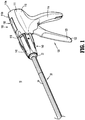
FIG. 1 is a front, perspective view of a surgical clip applier provided in accordance with the present disclosure including a handle assembly having an elongated assembly engaged therewith; -
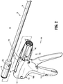
FIG. 2 is front, perspective view of the surgical clip applier shown inFIG. 1 with the elongated assembly removed from the handle assembly; -
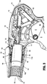
FIG. 3 is an enlarged, side view of the handle assembly of the surgical clip applier shown inFIG. 1 with a housing half removed; -
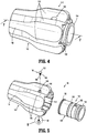
FIG. 4 is a side, perspective view of a rotation knob assembly of the surgical clip applier shown inFIG. 1 ; -
FIG. 5 is a side, perspective view of the rotation knob assembly shown inFIG. 4 with parts separated; -
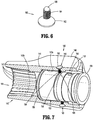
FIG. 6 is a side, perspective view of a screw of the rotation knob assembly shown inFIG. 4 ; -
FIG. 7 is a side, cross-sectional view taken along line 7-7 shown inFIG. 4 ; -
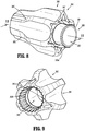
FIG. 8 is a side, perspective view of a rotation knob assembly according to another embodiment of the present disclosure; -
FIG. 9 is an end, perspective view of an outer knob of the rotation knob assembly shown inFIG. 8 ; -
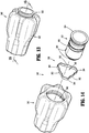
FIG. 10 is a side, perspective view of the rotation knob assembly shown inFIG. 8 with parts separated; -
FIG. 11 is a side, cross-sectional view taken along line 11-11 shown inFIG. 8 ; -
FIG. 12 is an end, cross-sectional view taken along line 12-12 shown inFIG. 11 ; -
FIG. 13 is a side, perspective view of a rotation knob assembly according to another embodiment of the present disclosure; -
FIG. 14 is a side, perspective view of the rotation knob assembly shown inFIG. 13 with parts separated; -
FIG. 15 is a side, cross-sectional view taken along line 15-15 shown inFIG. 13 ; -
FIG. 16 is an end, cross-sectional view taken along line 16-16 shown inFIG. 15 ; -
FIG. 17 is a side, perspective view of a rotation knob assembly according to another embodiment of the present disclosure with parts separated; -
FIG. 18 is a side, cross-sectional view of the rotation knob assembly shown inFIG. 17 ; and -
FIG. 19 is a cross-sectional end view taken along line 19-19 shown inFIG. 18 . - As detailed herein and shown in the drawing figures, as is traditional when referring to relative positioning on a surgical instrument, the term "proximal" refers to the end of the apparatus or component thereof which is closer to the user and the term "distal" refers to the end of the apparatus or component thereof which is further away from the user. Further, to the extent consistent, any or all of the aspects and features detailed herein may be used in conjunction with any or all of the other aspects and features detailed herein.
- The present disclosure provides rotation knob assemblies for surgical instruments. Although detailed herein as incorporated into a surgical clip applier, the rotation knob assemblies of the present disclosure may alternatively be incorporated into any suitable surgical instrument.
- Turning to
FIGS. 1 and2 , a surgical clip applier according to aspects of the present disclosure is shown generally asclip applier 10. Theclip applier 10 generally includes ahandle assembly 100 and anadapter assembly 20 selectively connectable to thehandle assembly 100. Thehandle assembly 100 is configured to operate theadapter assembly 20 upon connection thereto, and may be configured as a sterilizable, reusable component such that handleassembly 100 may be repeatedly used with different and/or additional elongated assemblies (not shown) during the course of one or more surgical procedures. Theadapter assembly 20 may be configured as single-use disposable component, limited-use disposable components, or reusable components, depending upon a particular purpose and/or the configuration of the particular elongated assembly. In either configuration, the need formultiple handle assemblies 100 is obviated and, instead, the surgeon need only select an appropriate elongated assembly, and connect that elongated assembly to thehandle assembly 100 in preparation for use. - The
handle assembly 100 includes ahousing 110, an actuation mechanism 120 (FIG. 3 ) operably disposed within thehousing 110, a latch assembly 130 (FIG. 3 ) operably disposed withinhousing 110, and arotation knob assembly 140 operably coupled to a distal portion ofhousing 110. Thehousing 110 supports and/or encloses the operating components ofhandle assembly 100, theactuation mechanism 120 is configured to enable selective firing of one or more surgical clips (not shown) from the end effector (not shown) of the attachedadapter assembly 20. Thelatch mechanism 130 is configured to facilitate releasable locking engagement of theadapter assembly 20 withhandle assembly 100. Therotation knob assembly 140 enables the selective rotation of the attachedadapter assembly 20 relative to thehousing 110. - The
handle assembly 100 will only be described to the extent necessary to fully disclose the aspects of the present disclosure. For a detailed description of the operation and function of an exemplary handle assembly, including an exemplary actuation mechanism and an exemplary latch assembly, please refer to commonly owned U.S. Prov. Pat. App. Ser. No.62/581,144 PCT/CN2016/096666 PCT/CN2016/071178 - Referring to
FIGS. 1 and2 , theadapter assembly 20 of theclip applier 10 generally includes aproximal hub 22, anelongated shaft 24 extending distally from theproximal hub 22, an end effector assembly (not shown) disposed towards a distal end portion of theelongated shaft 24, and an inner drive assembly (not shown) operably coupled between thehandle assembly 100 and the end effector assembly whenadapter assembly 20 is engaged with thehandle assembly 100, to enable the sequential firing of at least one surgical clip (not shown) about tissue. The end effector may be integrally formed with theadapter assembly 20, or may be a separate component releasably secured to theadapter assembly 20. The end effector assembly may be configured to fire surgical clips similar to those shown and described inU.S. Patent Nos. 7,819,886 or7,905,890 , the content of each of which is hereby incorporated herein by reference in its entirety. - With additional reference to
FIG. 3 , thehousing 110 of thehandle assembly 100 may be formed from first andsecond housing halves body portion 112 and a fixedhandle portion 114 depending from thebody portion 112. Thebody portion 112 of thehousing 110 includes adistal nose 116 defining a distal opening 117 (FIG. 3 ) therethrough. A proximal end portion of theproximal hub 22 of theadapter assembly 20 is configured to extend at least partially through thedistal opening 117 of thedistal nose 116 of thehousing 110 when theadapter assembly 20 is engaged with thehandle assembly 100. - The
distal nose 116 of thebody portion 112 of thehousing 110 further includes anannular recess 119 defined on an interior surface thereof surrounding thedistal opening 117. Theannular recess 119 is configured to receive anannular protrusion 154 of aninner collar 150 of therotation knob assembly 140 to secure therotation knob assembly 140 with thedistal nose 116 of thebody portion 112 of thehousing 110. To this end, theannular recess 119 and/or theannular protrusion 154 of theinner collar 150 may include one or more keying features to facilitate rotationally lock theinner collar 150 to thedistal nose 116 of thehousing 110. In embodiments, and as shown, theinner collar 150 defines an opening 153 (FIG. 5 ) that receives a tab (not shown) extending from thedistal nose 116 of thebody portion 112 of thehousing 110 for longitudinally and rotationally locking theinner collar 150 relative to thehousing 110. - With reference to
FIGS. 3-7 , anouter knob 142 of therotation knob assembly 140 is rotatably coupled to thedistal nose 116 of thebody portion 112 of thehousing 110 and is configured to receive the proximal hub 22 (FIG. 1 ) of theadapter assembly 20. As described below, theouter knob 142 of therotation knob assembly 140 is coupled to theadapter assembly 20 in fixed rotational engagement therewith to enable selective rotation of theadapter assembly 20 relative to thehousing 110 upon rotation of anouter knob 142 relative tohousing 110. Therotation knob assembly 140 includes theouter knob 142, theinner collar 150, and a pair ofscrews 160 rotatably securing theouter knob 142 to theinner collar 150. - The
outer knob 142 of therotation knob assembly 140 may be formed from a polymeric material, e.g., a biocompatible, sterilizable plastic, or other suitable material, and includes abody 144 defining a substantially cone shaped-configuration tapering in diameter from a proximal end portion to a distal end portion thereof, although other suitable configurations are also contemplated. Thebody 144 defines a plurality offlutes 146 arranged radially about thebody 144 to facilitate grasping or gripping of thebody 144 by a user at any rotational orientation to enable rotation of therotation knob assembly 140. - The
body 144 of theouter knob 142 of therotation knob assembly 140 defines a longitudinally-extendinglumen 143 therethrough. The longitudinally-extendinglumen 143 includes aproximal portion 143a and adistal portion 143b which may define equal or different diameters, e.g., theproximal portion 143a may define a larger diameter as compared to thedistal portion 143b. Theproximal portion 143a oflumen 143 communicates with the proximal opening of thebody 144 of theouter knob 142. Thebody 144 of theouter knob 142 defines a pair of threaded transverse apertures 145 (FIG. 5 , only one shown) that communicate with theproximal portion 143a of thelumen 143. Each of the threaded transverse apertures 145 is configured to receive one of thescrews 160 as detailed below. - The
distal portion 143b of thelumen 143 communicates with the distal opening of thebody 144 of theouter knob 142 at the distal end thereof and with theproximal portion 143a of thelumen 143 at the proximal end thereof. Thebody 144 includes a plurality of longitudinally-extendinggrooves 147 arranged annularly on an interior surface thereof and disposed about at least a portion of thedistal portion 143b of thelumen 143. Thegrooves 147 are configured to slidably receiveindexing protrusions 22a (FIG. 2 ) of theproximal hub 22 ofadapter assembly 20 to rotationally fix theproximal hub 22 relative to theouter knob 142 upon insertion ofproximal hub 22 intohandle assembly 100. - The
inner collar 150 of therotation knob assembly 140 may be formed from a metal, e.g., stainless steel, or other suitable material, and includes abody 152 defining a longitudinally-extending lumen 151 therethrough. Theinner collar 150 further includes anannular protrusion 154 disposed about a proximal end portion thereof and adistal head 156 disposed about a distal end portion thereof. Theinner collar 150 defines an annular groove orchannel 155 defined within an exterior surface of theinner collar 150, disposed between theannular protrusion 154 and thedistal head 156. Theannular protrusion 154, as noted above, is configured for receipt within theannular recess 119 of thedistal nose 116 of the housing 110 (seeFIG. 3 ) to engage theinner collar 150 with thedistal nose 116 of thebody portion 112 of thehousing 110, e.g., upon engagement of the first andsecond housing halves FIG. 1 ) forming thehousing 110 with one another. As noted above, theinner collar 150 defines theopening 154 for receiving a tab (not shown) extending from thedistal nose 116 of thehousing 110 for rotationally locking theinner collar 150 relative to thehousing 110. - The
inner collar 150 is configured to be received within theproximal portion 143a of thelumen 143 of thebody 144 of theouter knob 142. Theinner collar 150 is configured such that theannular groove 155 aligns with the pair of threaded transverse apertures 145 in thebody 144 of theouter knob 142 when theouter knob 142 is received about theinner collar 150. - With particular reference to
FIG. 6 , eachscrew 160 of therotation knob assembly 140 includes ahead portion 162, a threadedpost portion 164 extending from thehead 162, and aball portion 166 disposed on an end of the threadedpost portion 164. In embodiments, at least theball portion 166 of thescrews 160 is formed from PLASTITE ® (a registered trademark of Research Engineering & Manufacturing, Inc., Rhode Island) or other low friction or lubricious material to facilitate rotation of theouter knob 142 of therotation knob assembly 140 relative to theinner collar 150. In alternative embodiments, the screws are biased radially inward to facilitate assembly of the rotation knob assembly. - Turing to
FIG. 7 , thescrews 160 of therotation knob assembly 140 are received within the transverse apertures 145 defined through thebody 144 of theouter knob 142, and are oriented such that theball portions 166 of thescrews 160 protrude radially inwardly into theproximal portion 143a of thelumen 143 of thebody 144 of theouter knob 142. As noted above, theannular groove 155 of theinner collar 150 aligns with the transverse apertures 145 in theouter knob 142 when theouter knob 142 is received about theinner collar 150. In this manner, theball portions 166 of thescrews 166 extending from the transvers apertures 145 are received within theannular groove 155 of theinner collar 150 to rotatably retain theouter knob 142 relative to theinner collar 150. Theball portions 166 of thescrews 160 are configured to provide minimal friction withinner collar 150 to allow ease of rotation of theouter knob 142 relative to theinner collar 150. Theouter knob 142 may be rotated continuously through an infinite number of positions. - With reference now to
FIGS. 8-12 , a rotation knob assembly according to another embodiment of the present disclosure is shown generally asrotation knob assembly 240. Therotation knob assembly 240 is substantially similar torotation knob assembly 140 described herein above, and will only be described in detail as relates to the differences therebetween. - The
rotation knob assembly 240 includes anouter knob 242, aninner collar 250, and abearing assembly 260 rotatable securing theouter knob 242 to theinner collar 250. Theouter knob 242 includes abody 244 defining a longitudinally-extendinglumen 243 therethrough. The longitudinally-extendinglumen 243 includes aproximal portion 243a and adistal portion 243b. Thebody 244 of theouter knob 242 defines a plurality of longitudinally extendingopenings 245 that communicate with theproximal portion 243a of thelumen 243. Each of thelongitudinal openings 245 is configured to receive a locking member 270 (FIG. 10 ) as detailed below. Thebody 244 of theouter knob 242 also defines a plurality ofnotches 247 extending radially outward from theproximal portion 243a of thelongitudinally extending lumen 243. Thenotches 247 accommodateprotrusions 266 of anannular body 264 of the bearingmember 262 of the bearingassembly 260. - The
inner collar 250 of therotation knob assembly 240 includes abody 252. Theinner collar 250 includes anannular protrusion 254 disposed about a proximal end portion thereof, anannular flange 256 disposed about a mid-portion thereof, and abearing surface 258 disposed between theannular protrusion 254 and theannular flange 256. As described below, the bearingsurface 258 of theinner collar 250 is configured to rotatably support the bearingmember 262 of the bearingassembly 260. - The bearing
assembly 260 of therotation knob assembly 240 includes the bearingmember 262 and the plurality offastening members 270. The bearingmember 262 includes anannular body 264 and a plurality ofprotrusions 266 extending radially outward from theannular body 264. Theannular body 264 of the bearingmember 266 is configured to be received about the bearingsurface 258 of theinner collar 250 and within theproximal portion 243a of thelumen 243 in theouter knob 242 of therotation knob assembly 240. Theprotrusions 266 of the bearingmember 262 are configured to be received within thenotches 247 in thebody 244 of theouter knob 242. Although shown as having threeprotrusions 266 with a triangular shape, it is envisioned that the bearingmember 262 may include any number ofprotrusions 266 and theprotrusions 266 may include any suitable shape. The number and shape of thenotches 247 in thebody 244 of theouter knob 242 correspond to the number and shape of theprotrusions 266. Each of theprotrusions 266 of the bearingmember 262 defines anopening 267 for engaging a proximal end of one of thefastener members 270. - The
fastener members 270 of therotation knob assembly 240 may include a threaded outer surface (not shown) for threading engagement with theprotrusions 266 of the bearingmember 262. Alternatively, thefastener members 270 may be received within theopenings 267 in theprotrusions 266 of the bearingmember 262 with a friction fit. Thefastener members 270 may be further secured to theprotrusions 266 of the bearingmember 262 with adhesive. In embodiments, either or both ofinner collar 250 and the bearingmember 262 are formed from PLASTITE ® or other low friction or lubricious material to facilitate rotation of the bearingmember 262 relative to theinner collar 250. Alternatively, either or both of the bearingmember 262 andinner collar 250 may include a friction reducing coating to facilitate rotation of theouter knob 242 about theinner collar 250. - With reference now to
FIG. 13-16 , another embodiment of a rotation knob assembly according to the present disclosure is shown generally asrotation knob assembly 340. Therotation knob assembly 340 is substantially similar torotation knob assemblies - The
rotation knob assembly 340 includes anouter knob 342, aninner collar 350, and asnap ring 360. Theouter knob 342 includes a body 344 defining a longitudinally-extendinglumen 343 therethrough. The longitudinally-extendinglumen 343 includes aproximal portion 343a and adistal portion 343b. The body 344 of theouter knob 342 defines anannular groove 345 disposed within theproximal portion 343a of thelongitudinally extending lumen 343. Theannular groove 345 is configured to receive a plurality offlange portions 364 of thesnap ring 360. Alternatively, the body 344 of theouter knob 342 includes a plurality of cutouts (not shown) for accommodating the plurality offlange portions 364 of the snap ring. - The
inner collar 350 of therotation knob assembly 340 includes a body 352. Theinner collar 350 includes anannular protrusion 354 disposed about a proximal end portion thereof anddistal head sections 356 disposed about a mid-portion thereof. Theinner collar 350 defines anannular groove 355 disposed between theannular protrusion 354 and theannular flange sections 356. As described below, theannular groove 355 is configured to accept thesnap ring 360 of therotation knob assembly 340. - The
snap ring 360 of therotation knob assembly 340 includes alternatingannular segments 362 andflange segments 364. Together theannular segments 362 define acylindrical opening 363 configured to be received within theannular groove 355 in theinner collar 350. Theflange segments 364 of thesnap ring 360 extend outwardly between theannular segments 362 and are configured to be received within theannular groove 345 in theproximal portion 343a of thelongitudinally extending lumen 343 of the body 352 of theouter knob 350. - The
snap ring 360 may be secured within theannular groove 345 of theouter knob 342 in a rotationally fixed condition such that thesnap ring 360 rotates along with theouter knob 342 when theouter knob 342 is rotated relative to theinner collar 350. In this manner, thesnap ring 360 is rotatably received within theannular groove 355 of theinner collar 350 and thesnap ring 360 andouter knob 342 rotate relative to theinner collar 350. Alternatively, thesnap ring 360 may be secured within theannular groove 345 of theinner collar 350 in a rotationally fixed condition such that thesnap ring 360 does not rotate with theouter knob 342 as theouter knob 342 is rotated relative to theinner collar 350. In this manner, thesnap ring 360 is rotatably received within theannular groove 345 of theouter knob 342 and theouter knob 342 rotates relative to thesnap ring 360. In embodiments thesnap ring 360 may be rotationally received within theannular groove 345 of theouter knob 342 and theannular groove 355 of theinner collar 350 such that thesnap ring 360 may rotate relative to either or both of theouter knob 342 andinner collar 350 when theouter knob 342 is rotated relative to theinner collar 350. - With reference now to
FIG. 17-19 , still another embodiment of a rotation knob assembly according to the present disclosure is shown generally asrotation knob assembly 440. Therotation knob assembly 440 is substantially similar torotation knob assemblies - The
rotation knob assembly 440 includes anouter knob 442, aninner collar 450, and abearing assembly 460. Theouter knob 442 includes a body 444 defining a longitudinally-extendinglumen 443 therethrough. The longitudinally-extendinglumen 443 includes aproximal portion 443a and adistal portion 443b. The body 444 includes a plurality of longitudinally-extending grooves 447 arranged annularly on an interior surface thereof and disposed about at least a portion of theproximal portion 443a of thelumen 443. The grooves 447 frictionally engage a groovedouter surface 456 of theinner collar 450. - The
inner collar 450 of therotation knob assembly 440 includes a body 452. Theinner collar 450 includes abearing surface 454 disposed about a proximal end portion thereof and the groovedouter surface 456 about a distal portion thereof. A plurality of pairedsemi-spherical recesses 453 are defined in thebearing surface 454 of theinner collar 450. As described below, thesemi-spherical recesses 453support ball bearings 466 of the bearingassembly 460. The groovedouter surface 456 of theinner collar 450 frictionally engages and rotationally fixes theinner collar 450 to theouter knob 442. - The bearing
assembly 460 of therotation knob assembly 440 includes anannular housing 462 having first andsecond housing halves annular housing 462 includes proximal and distalannular flanges annular flange 464a of theannular housing 462 is configured to be received within the annular recess 119 (FIG. 3 ) in the distal nose 116 (FIG. 3 ) of the body portion 114 (FIG. 3 ) of thehousing 110. The distalannular flange 464b of theannular housing 462 is configured to be received within theproximal portion 443a of thelumen 443 of the body 444 of theouter knob 442 to support theinner collar 450 within theouter knob 442. - The
annular housing 462 of the bearingassembly 460 defines a pair ofannular grooves 463 that align with the plurality of pairedsemi-spherical recesses 453 in theinner collar 450 when theinner collar 450 is received within theouter knob 442. Theannular grooves 463 cooperate with thesemi-spherical recesses 453 to support theball bearings 466. Receipt of theball bearings 466 within thesemi-spherical recesses 453 and theannular grooves 463 longitudinally fixes theouter knob 442 and theinner collar 450 relative to thehousing 112 of thehandle assembly 100 and facilitates rotation of theouter knob 442 relative to thehousing 110. - It should be understood that the foregoing description is only illustrative of the present disclosure. Various alternatives and modifications can be devised by those skilled in the art without departing from the disclosure. Accordingly, the present disclosure is intended to embrace all such alternatives, modifications and variances. The embodiments described with reference to the attached drawing figures are presented only to demonstrate certain examples of the disclosure. Other elements, steps, methods and techniques that are insubstantially different from those described above and/or in the appended claims are also intended to be within the scope of the disclosure.
- The invention is described by the following numbered paragraphs:-
- 1. A rotation knob assembly for a surgical instrument, the rotation knob assembly comprising:
- an outer knob including a body defining a lumen extending longitudinally therethrough, the lumen including a proximal lumen portion and a distal lumen portion;
- an inner collar disposed within the proximal lumen portion of the outer knob and rotatably engaged with the outer knob, the inner collar defining an annular groove; and
- a plurality of screws protruding radially inwardly through the body of the outer knob into the proximal lumen portion of the outer knob, each screw of the plurality of screws including a ball portion received within the annular groove of the inner collar such that, upon rotation of the outer knob relative to the inner collar, the ball portions slide along the annular groove.
- 2. The rotation knob assembly of paragraph 1, wherein the plurality of screws includes two screws.
- 3. The rotation knob assembly of paragraph 1, wherein the plurality of screws is formed of low friction material.
- 4. The rotation knob assembly of paragraph 1, wherein the inner collar includes an annular protrusion for securing the inner collar to a handle assembly.
- 5. The rotation knob assembly of paragraph 4, wherein the annular protrusion is configured to longitudinally fix the inner collar to a handle assembly.
- 6. The rotation knob assembly of paragraph 4, wherein the annular protrusion is configured to rotationally fix the inner collar to a handle assembly.
- 7. The rotation knob assembly of paragraph 1, wherein the body defining the distal lumen portion includes longitudinal grooves.
- 8. A rotation knob assembly for a surgical instrument, the rotation knob assembly comprising:
- an outer knob including a body defining a lumen extending longitudinally therethrough, the lumen including a proximal lumen portion and a distal lumen portion;
- an inner collar disposed within the proximal lumen portion of the outer knob and rotatably engaged with the outer knob, the inner collar defining an annular groove; and
- a bearing assembly disposed within the outer knob and received about the inner collar, the bearing assembly including an annular ring received within the annular groove of the inner collar and a plurality of outwardly extending projections extending into the outer knob, wherein the plurality of projections rotationally fixes the bearing assembly to the outer knob.
- 9. The rotation knob assembly of paragraph 8, wherein the inner collar includes an annular protrusion for securing the inner collar to a handle assembly.
- 10. The rotation knob assembly of paragraph 9, wherein the annular protrusion is configured to longitudinally fix the inner collar to a handle assembly.
- 11. The rotation knob assembly of paragraph 9, wherein the annular protrusion is configured to rotationally fix the inner collar to a handle assembly.
- 12. The rotation knob assembly of paragraph 8, wherein the body defines longitudinal grooves about the distal lumen portion.
- 13. A rotation knob assembly for a surgical instrument, the rotation knob assembly comprising:
- an outer knob including a body defining a lumen extending longitudinally therethrough and an annular groove, the lumen including a proximal lumen portion and a distal lumen portion;
- an inner collar disposed within the proximal lumen portion of the outer knob and rotatably engaged with the outer knob, the inner collar defining an annular groove; and
- a snap ring disposed within the outer knob and received about the inner collar, the snap ring including a plurality of alternating annular segments and flange segments, the annular segments being received within the annular groove in the inner collar and the flange segments being received within the annular groove of the outer knob, wherein the outer collar is rotatable relative to the inner collar.
- 14. The rotation knob assembly of paragraph 13, wherein the snap ring is rotationally fixed relative to the inner collar.
- 15. The rotation knob assembly of paragraph 13, wherein the snap ring is rotationally fixed relative to the outer knob.
- 16. The rotation knob assembly of paragraph 13, wherein the inner collar includes an annular protrusion for securing the inner collar to a handle assembly.
- 17. The rotation knob assembly of
paragraph 16, wherein the annular protrusion is configured to longitudinally fix the inner collar to a handle assembly. - 18. The rotation knob assembly of
paragraph 16, wherein the annular protrusion is configured to rotationally fix the inner collar to a handle assembly. - 19. The rotation knob assembly of paragraph 13, wherein the body defines longitudinal grooves about the distal lumen portion.
- 20. A rotation knob assembly for a surgical instrument, the rotation knob assembly comprising:
- an outer knob including a body defining a lumen extending longitudinally therethrough, the lumen including a proximal lumen portion and a distal lumen portion;
- an inner collar disposed within the proximal lumen portion of the outer knob and rotatably engaged with the outer knob, the inner collar including a bearing surface; and
- a bearing assembly disposed within the proximal lumen portion of the outer knob between the body of the outer knob and the inner collar, the bearing assembly including an annular housing and a plurality of paired ball bearings, the annular housing including an annular protrusion for securing the annular housing to a handle assembly, wherein the inner collar and the outer knob are rotationally fixed relative to each other.
- 21. The rotation knob assembly of
paragraph 20, wherein the annular housing defines a pair of annular grooves and the bearing surface of the inner collar defines a plurality of paired semi-spherical recesses, wherein the pair of annular grooves and the plurality of paired semi-spherical recesses define a plurality of paired cavities for receiving the plurality of paired ball bearings. - 22. The rotation knob assembly of paragraph 21, wherein the plurality of paired ball bearings is rotatably supported within the plurality of paired cavities.
- 23. The rotation knob assembly of
paragraph 20, wherein the annular housing includes first and second housing halves.
Claims (15)
- A rotation knob assembly for a surgical instrument, the rotation knob assembly comprising:an outer knob including a body defining a lumen extending longitudinally therethrough, the lumen including a proximal lumen portion and a distal lumen portion;an inner collar disposed within the proximal lumen portion of the outer knob and rotatably engaged with the outer knob, the inner collar defining an annular groove; anda plurality of screws protruding radially inwardly through the body of the outer knob into the proximal lumen portion of the outer knob, each screw of the plurality of screws including a ball portion received within the annular groove of the inner collar such that, upon rotation of the outer knob relative to the inner collar, the ball portions slide along the annular groove.
- The rotation knob assembly of claim 1, wherein the plurality of screws includes two screws; and/or wherein the plurality of screws is formed of low friction material; and/or wherein the inner collar includes an annular protrusion for securing the inner collar to a handle assembly.
- The rotation knob assembly of claim 4, wherein the annular protrusion is configured to longitudinally fix the inner collar to a handle assembly; or wherein the annular protrusion is configured to rotationally fix the inner collar to a handle assembly.
- The rotation knob assembly of any preceding claim, wherein the body defining the distal lumen portion includes longitudinal grooves.
- A rotation knob assembly for a surgical instrument, the rotation knob assembly comprising:an outer knob including a body defining a lumen extending longitudinally therethrough, the lumen including a proximal lumen portion and a distal lumen portion;an inner collar disposed within the proximal lumen portion of the outer knob and rotatably engaged with the outer knob, the inner collar defining an annular groove; anda bearing assembly disposed within the outer knob and received about the inner collar, the bearing assembly including an annular ring received within the annular groove of the inner collar and a plurality of outwardly extending projections extending into the outer knob, wherein the plurality of projections rotationally fixes the bearing assembly to the outer knob.
- The rotation knob assembly of claim 5, wherein the inner collar includes an annular protrusion for securing the inner collar to a handle assembly; preferably wherein the annular protrusion is configured to longitudinally fix the inner collar to a handle assembly; preferably wherein the annular protrusion is configured to rotationally fix the inner collar to a handle assembly.
- The rotation knob assembly of claim 5 or claim 6, wherein the body defines longitudinal grooves about the distal lumen portion.
- A rotation knob assembly for a surgical instrument, the rotation knob assembly comprising:an outer knob including a body defining a lumen extending longitudinally therethrough and an annular groove, the lumen including a proximal lumen portion and a distal lumen portion;an inner collar disposed within the proximal lumen portion of the outer knob and rotatably engaged with the outer knob, the inner collar defining an annular groove; anda snap ring disposed within the outer knob and received about the inner collar, the snap ring including a plurality of alternating annular segments and flange segments, the annular segments being received within the annular groove in the inner collar and the flange segments being received within the annular groove of the outer knob, wherein the outer collar is rotatable relative to the inner collar.
- The rotation knob assembly of claim 8, wherein the snap ring is rotationally fixed relative to the inner collar, or wherein the snap ring is rotationally fixed relative to the outer knob.
- The rotation knob assembly of claim 9, wherein the inner collar includes an annular protrusion for securing the inner collar to a handle assembly.
- The rotation knob assembly of claim 10, wherein the annular protrusion is configured to longitudinally fix the inner collar to a handle assembly; or wherein the annular protrusion is configured to rotationally fix the inner collar to a handle assembly.
- The rotation knob assembly of any of claims 8 to 11, wherein the body defines longitudinal grooves about the distal lumen portion.
- A rotation knob assembly for a surgical instrument, the rotation knob assembly comprising:an outer knob including a body defining a lumen extending longitudinally therethrough, the lumen including a proximal lumen portion and a distal lumen portion;an inner collar disposed within the proximal lumen portion of the outer knob and rotatably engaged with the outer knob, the inner collar including a bearing surface; anda bearing assembly disposed within the proximal lumen portion of the outer knob between the body of the outer knob and the inner collar, the bearing assembly including an annular housing and a plurality of paired ball bearings, the annular housing including an annular protrusion for securing the annular housing to a handle assembly, wherein the inner collar and the outer knob are rotationally fixed relative to each other.
- The rotation knob assembly of claim 13, wherein the annular housing defines a pair of annular grooves and the bearing surface of the inner collar defines a plurality of paired semi-spherical recesses, wherein the pair of annular grooves and the plurality of paired semi-spherical recesses define a plurality of paired cavities for receiving the plurality of paired ball bearings; preferably wherein the plurality of paired ball bearings is rotatably supported within the plurality of paired cavities.
- The rotation knob assembly of claim 14, wherein the annular housing includes first and second housing halves.
Applications Claiming Priority (2)
| Application Number | Priority Date | Filing Date | Title |
|---|---|---|---|
| US201862697418P | 2018-07-13 | 2018-07-13 | |
| US16/369,199 US10786273B2 (en) | 2018-07-13 | 2019-03-29 | Rotation knob assemblies for handle assemblies |
Publications (2)
| Publication Number | Publication Date |
|---|---|
| EP3593739A2 true EP3593739A2 (en) | 2020-01-15 |
| EP3593739A3 EP3593739A3 (en) | 2020-03-18 |
Family
ID=67253800
Family Applications (1)
| Application Number | Title | Priority Date | Filing Date |
|---|---|---|---|
| EP19185820.8A Withdrawn EP3593739A3 (en) | 2018-07-13 | 2019-07-11 | Rotation knob assemblies for handle assemblies |
Country Status (2)
| Country | Link |
|---|---|
| US (1) | US10786273B2 (en) |
| EP (1) | EP3593739A3 (en) |
Cited By (1)
| Publication number | Priority date | Publication date | Assignee | Title |
|---|---|---|---|---|
| KR20240050528A (en) * | 2022-10-11 | 2024-04-19 | 재단법인 아산사회복지재단 | Master device for remote intervention |
Families Citing this family (12)
| Publication number | Priority date | Publication date | Assignee | Title |
|---|---|---|---|---|
| US8465502B2 (en) | 2008-08-25 | 2013-06-18 | Covidien Lp | Surgical clip applier and method of assembly |
| US9358015B2 (en) | 2008-08-29 | 2016-06-07 | Covidien Lp | Endoscopic surgical clip applier with wedge plate |
| US8403945B2 (en) | 2010-02-25 | 2013-03-26 | Covidien Lp | Articulating endoscopic surgical clip applier |
| US8968337B2 (en) | 2010-07-28 | 2015-03-03 | Covidien Lp | Articulating clip applier |
| CA2958160A1 (en) | 2016-02-24 | 2017-08-24 | Covidien Lp | Endoscopic reposable surgical clip applier |
| US10492795B2 (en) | 2016-11-01 | 2019-12-03 | Covidien Lp | Endoscopic surgical clip applier |
| US11583291B2 (en) | 2017-02-23 | 2023-02-21 | Covidien Lp | Endoscopic surgical clip applier |
| US10675043B2 (en) | 2017-05-04 | 2020-06-09 | Covidien Lp | Reposable multi-fire surgical clip applier |
| US11376015B2 (en) | 2017-11-03 | 2022-07-05 | Covidien Lp | Endoscopic surgical clip applier and handle assemblies for use therewith |
| US11779340B2 (en) | 2020-01-02 | 2023-10-10 | Covidien Lp | Ligation clip loading device |
| US12114866B2 (en) | 2020-03-26 | 2024-10-15 | Covidien Lp | Interoperative clip loading device |
| CA3185437A1 (en) * | 2022-06-09 | 2023-12-09 | Bombardier Inc. | Aircraft system controller and associated method |
Citations (2)
| Publication number | Priority date | Publication date | Assignee | Title |
|---|---|---|---|---|
| US7819886B2 (en) | 2004-10-08 | 2010-10-26 | Tyco Healthcare Group Lp | Endoscopic surgical clip applier |
| US7905890B2 (en) | 2004-10-08 | 2011-03-15 | Tyco Healthcare Group Lp | Endoscopic surgical clip applier |
Family Cites Families (789)
| Publication number | Priority date | Publication date | Assignee | Title |
|---|---|---|---|---|
| US3120230A (en) | 1960-10-24 | 1964-02-04 | Jack H Sanders | Surgical clamp |
| US3363628A (en) | 1964-09-28 | 1968-01-16 | Peter B Samuels | Hemostatic clip |
| US3675688A (en) | 1970-04-27 | 1972-07-11 | United States Surgical Corp | Instrument for ligating, suturing and dividing organic tubular structures |
| US3735762A (en) | 1970-04-27 | 1973-05-29 | Us Corp Baltimo E | Instrument for ligating suturing and dividing organic tubular structures |
| US3638847A (en) | 1970-07-06 | 1972-02-01 | United States Surgical Corp | Ratchet-driven cartridge for surgical instruments |
| US3867944A (en) | 1972-10-27 | 1975-02-25 | Wood Ernest C | Hemostatic clip and applicator therefor |
| US4412539A (en) | 1976-10-08 | 1983-11-01 | United States Surgical Corporation | Repeating hemostatic clip applying instruments and multi-clip cartridges therefor |
| US4226242A (en) | 1977-09-13 | 1980-10-07 | United States Surgical Corporation | Repeating hemostatic clip applying instruments and multi-clip cartridges therefor |
| US4611595A (en) | 1977-08-05 | 1986-09-16 | Charles H. Klieman | Spring activated hemostatic clip applicator |
| US4242902A (en) | 1978-05-11 | 1981-01-06 | United States Surgical Corporation | Surgical clip applicator |
| US4418694A (en) | 1979-06-18 | 1983-12-06 | Ethicon, Inc. | Non-metallic, bio-compatible hemostatic clips |
| US4662374A (en) | 1979-08-02 | 1987-05-05 | American Hospital Supply Corp. | Ligator device |
| US4296751A (en) | 1979-08-02 | 1981-10-27 | Blake Joseph W Iii | Surgical device |
| US4532925A (en) | 1979-08-02 | 1985-08-06 | Joseph W. Blake, III | Ligator device |
| US4372316A (en) | 1979-08-02 | 1983-02-08 | Blake Joseph W Iii | Surgical device |
| US4480640A (en) | 1980-04-22 | 1984-11-06 | Senco Products, Inc. | Ligating device |
| US4408603A (en) | 1980-10-24 | 1983-10-11 | Blake Joseph W Iii | Surgical device |
| US4500024A (en) | 1980-11-19 | 1985-02-19 | Ethicon, Inc. | Multiple clip applier |
| CA1163889A (en) | 1981-02-02 | 1984-03-20 | Allegiance Corporation | Surgical device |
| US4522207A (en) | 1981-02-06 | 1985-06-11 | Charles H. Klieman | Spring activated hemostatic clip applicator |
| US4646740A (en) | 1981-02-23 | 1987-03-03 | Edward Weck & Co., Inc. | Automatic hemoclip applier |
| US4662373A (en) | 1981-06-29 | 1987-05-05 | American Cyanamid Company | Surgical ligating instrument |
| US4576166A (en) | 1981-06-29 | 1986-03-18 | American Cyanamid Company | Surgical ligating instrument |
| US4498476A (en) | 1981-08-27 | 1985-02-12 | Ethicon, Inc. | Non-metallic, bio-compatible hemostatic clips with interlocking latch means |
| US4487204A (en) | 1981-10-14 | 1984-12-11 | Nomel | Device for applying haemostatic clips |
| US4471780A (en) | 1982-02-05 | 1984-09-18 | Ethicon, Inc. | Multiple ligating clip applier instrument |
| US4480641A (en) | 1982-02-05 | 1984-11-06 | Ethicon, Inc. | Tip configuration for a ligating clip applier |
| US4491133A (en) | 1982-02-05 | 1985-01-01 | Ethicon, Inc. | Folding cartridge for a multiple clip applier |
| US4509518A (en) | 1982-02-17 | 1985-04-09 | United States Surgical Corporation | Apparatus for applying surgical clips |
| US4487205A (en) | 1982-04-26 | 1984-12-11 | Ethicon, Inc. | Non-metallic, bio-compatible hemostatic clips |
| US4827930A (en) | 1982-06-28 | 1989-05-09 | Codman & Shurtleff, Inc. | Reinforcing closer for aneurysm clip |
| US4545377A (en) | 1982-09-24 | 1985-10-08 | Ethicon, Inc. | Non-metallic, bio-compatible hemostatic clips (two piece configured to lock tighter the larger the vessel being closed) |
| US4492232A (en) | 1982-09-30 | 1985-01-08 | United States Surgical Corporation | Surgical clip applying apparatus having fixed jaws |
| US4815466A (en) | 1982-09-30 | 1989-03-28 | Perlin Alfred R | Surgical clip |
| US4512345A (en) | 1982-09-30 | 1985-04-23 | United States Surgical Corporation | Surgical clip applying apparatus, and clips and clip train for use therein |
| US4674504A (en) | 1982-10-06 | 1987-06-23 | Klieman Charles H | Spring activated hemostatic clip applicator |
| US4534351A (en) | 1982-10-20 | 1985-08-13 | Senmed, Inc. | Ligator |
| US4796625A (en) | 1982-11-15 | 1989-01-10 | Codman & Shurtleff, Inc. | Aneurysm clip |
| US4562839A (en) | 1983-01-06 | 1986-01-07 | Blake Joseph W Iii | Surgical instrument |
| US4556058A (en) | 1983-08-17 | 1985-12-03 | United States Surgical Corporation | Apparatus for ligation and division with fixed jaws |
| US4602631A (en) | 1983-09-08 | 1986-07-29 | Noboru Funatsu | Forceps for clamping surgical clips |
| DE3335985C2 (en) | 1983-10-04 | 1986-12-04 | Aesculap-Werke Ag Vormals Jetter & Scheerer, 7200 Tuttlingen | Magazine for holding C-shaped scalp clips |
| US4637395A (en) | 1983-10-04 | 1987-01-20 | Aesculap-Werke Ag | Applicator for C-shaped scalp clips |
| US4549544A (en) | 1983-10-31 | 1985-10-29 | Senmed, Inc. | Clip stop for a surgical ligating instrument |
| US4733664A (en) | 1983-12-01 | 1988-03-29 | University Of New Mexico | Surgical clip, applier, and method |
| US4929240A (en) | 1983-12-01 | 1990-05-29 | University Of New Mexico | Surgical clip and applier |
| US4557263A (en) | 1984-01-23 | 1985-12-10 | United States Surgical Corporation | Apparatus for applying surgical clips |
| US4576165A (en) | 1984-01-23 | 1986-03-18 | United States Surgical Corporation | Surgical ligation and cutting device with safety means |
| US4932955A (en) | 1984-06-29 | 1990-06-12 | Baxter International Inc. | Clip |
| US4616650A (en) | 1984-07-27 | 1986-10-14 | United States Surgical Corporation | Apparatus for applying surgical clips |
| US4598711A (en) | 1984-08-09 | 1986-07-08 | American Cyanamid Company | Surgical instrument |
| US4590937A (en) | 1985-01-07 | 1986-05-27 | American Cyanamid Company | Nonmetallic surgical clip |
| US5127915A (en) | 1984-10-29 | 1992-07-07 | Mattson Philip D | Surgical instrument for severing and clamping an umbilical cord |
| US4572183A (en) | 1984-11-26 | 1986-02-25 | Senmed, Inc. | Positive feed system for a surgical ligating instrument |
| GB2168990B (en) | 1984-12-22 | 1988-07-06 | Hoechst Gosei Kk | Dispersion of solvent-suspendible pressure sensitive adhesive particles and pressure sensitive adhesive sheet utilizing the dispersion |
| US4821721A (en) | 1985-01-14 | 1989-04-18 | Thomas J. Fogarty | Apparatus and method for applying hemostatic scalp clips |
| US4671278A (en) | 1985-01-14 | 1987-06-09 | Thomas J. Fogarty | Scalp hemostatic clip and dispenser therefor |
| US5122150A (en) | 1985-03-27 | 1992-06-16 | Puig Ana E | Neurosurgical clip applier |
| US4616651A (en) | 1985-04-15 | 1986-10-14 | Ethicon, Inc. | Surgical clip applier instrument adapter jaws |
| US5047038A (en) | 1985-07-01 | 1991-09-10 | Edward Weck Incorporated | Automatic hemostatic clip applier |
| US4712549A (en) | 1985-07-01 | 1987-12-15 | Edward Weck & Co. | Automatic hemostatic clip applier |
| US4702247A (en) | 1985-08-20 | 1987-10-27 | American Hospital Supply Corporation | Ligating clip |
| US4706668A (en) | 1985-09-16 | 1987-11-17 | B & B Tools | Aneurysm clip pliers |
| DE3533423A1 (en) | 1985-09-19 | 1987-03-26 | Wolf Gmbh Richard | APPLICATOR PLIERS FOR SURGICAL HANDLING FOR USE IN ENDOSCOPY |
| US4671282A (en) | 1985-10-04 | 1987-06-09 | Tretbar Lawrence L | Clip apparatus |
| US4696396A (en) | 1985-12-19 | 1987-09-29 | Samuels Peter B | Hemostatic clip cartridge |
| US4681107A (en) | 1985-12-31 | 1987-07-21 | Kees Surgical Specialty Co. | Device for holding an aneurysm clip |
| US4658822A (en) | 1985-12-31 | 1987-04-21 | Kees Jr George | Aneurysm clip |
| US4660558A (en) | 1985-12-31 | 1987-04-28 | Kees Jr George | Aneurysm clip and method of manufacture |
| US4733666A (en) | 1986-01-13 | 1988-03-29 | Texas Tech University Health Sciences Center | Surgical clip for cholangiography |
| US4777950A (en) | 1986-04-11 | 1988-10-18 | Kees Surgical Specialty Co. | Vascular clip |
| US4967949A (en) | 1986-07-11 | 1990-11-06 | Vastech Medical Products Inc. | Apparatus for effecting occlusion of the vas deferens |
| US4726372A (en) | 1986-09-19 | 1988-02-23 | Metatech Corporation | Hemostatic clip |
| US4856517A (en) | 1986-09-22 | 1989-08-15 | Collins Jason H | Umbilical cord clamp apparatus |
| DE3704760C1 (en) | 1987-02-16 | 1988-03-03 | Aesculap Werke Ag | Application device for C-shaped scalp clips |
| US4929239A (en) | 1987-02-16 | 1990-05-29 | Aesculap-Werke Ag Vormals Jetter & Scheerer | Device for filling the magazine of a scalp clip applicator with C-shaped scalp clips |
| US4765335A (en) | 1987-03-16 | 1988-08-23 | Intermar, Inc. | Aneurysm clip |
| US4850355A (en) | 1987-04-06 | 1989-07-25 | Richard-Allan Medical Industries, Inc. | Hemostatic clip applicator for applying multiple hemostatic clips |
| US4799481A (en) | 1987-04-08 | 1989-01-24 | Ethicon, Inc. | Surgical hemostatic clips |
| US4777949A (en) | 1987-05-08 | 1988-10-18 | Metatech Corporation | Surgical clip for clamping small blood vessels in brain surgery and the like |
| US4822348A (en) | 1987-05-13 | 1989-04-18 | Donn Casey | Surgical clips |
| US5542949A (en) | 1987-05-14 | 1996-08-06 | Yoon; Inbae | Multifunctional clip applier instrument |
| US5366459A (en) | 1987-05-14 | 1994-11-22 | Inbae Yoon | Surgical clip and clip application procedures |
| US5171250A (en) | 1987-05-14 | 1992-12-15 | Inbae Yoon | Surgical clips and surgical clip applicator and cutting and transection device |
| US4817604A (en) | 1987-09-11 | 1989-04-04 | Smith Iii Ray C | Disposable cholangiogram clip |
| US4834096A (en) | 1987-10-26 | 1989-05-30 | Edward Weck Incorporated | Plastic ligating clips |
| GB2212201B (en) | 1987-11-10 | 1992-06-03 | Donn Casey | Surgical clip |
| US6974475B1 (en) | 1987-12-08 | 2005-12-13 | Wall W Henry | Angioplasty stent |
| US5197970A (en) | 1988-01-15 | 1993-03-30 | United States Surgical Corporation | Surgical clip applicator |
| US5383881A (en) | 1989-07-18 | 1995-01-24 | United States Surgical Corporation | Safety device for use with endoscopic instrumentation |
| US5084057A (en) | 1989-07-18 | 1992-01-28 | United States Surgical Corporation | Apparatus and method for applying surgical clips in laparoscopic or endoscopic procedures |
| US5030226A (en) | 1988-01-15 | 1991-07-09 | United States Surgical Corporation | Surgical clip applicator |
| US5129885A (en) | 1990-02-13 | 1992-07-14 | United States Surgical Corporation | Safety device for trocars and surgical instruments therefor |
| US5100420A (en) | 1989-07-18 | 1992-03-31 | United States Surgical Corporation | Apparatus and method for applying surgical clips in laparoscopic or endoscopic procedures |
| US5049152A (en) | 1989-03-07 | 1991-09-17 | Richard-Allan Medical Industries | Hemostatic clip applicator |
| JPH01310654A (en) | 1988-06-09 | 1989-12-14 | Shigekiyo Fujita | Cerebral aneurysm clip |
| US5053045A (en) | 1988-09-16 | 1991-10-01 | Schmidt Ferenc J | Surgical clip |
| FR2637489A1 (en) | 1988-10-07 | 1990-04-13 | Lachkar Alain | AUTOMATIC CLIPS CLIP |
| US5059202A (en) | 1988-10-27 | 1991-10-22 | The Montefiore Hospital Association Of Western Pennsylvania | Tendon approximator |
| US4957500A (en) | 1988-10-27 | 1990-09-18 | Montefiore Hospital Association Of Western Pennsylvania | Normally closed clamp |
| US4983176A (en) | 1989-03-06 | 1991-01-08 | University Of New Mexico | Deformable plastic surgical clip |
| US5062846A (en) | 1989-03-28 | 1991-11-05 | Edward Weck Incorporated | Penetrating plastic ligating clip |
| US5062563A (en) | 1989-04-10 | 1991-11-05 | United States Surgical Corporation | Fascia stapler |
| US5104395A (en) | 1989-07-03 | 1992-04-14 | Edward Weck Incorporated | Automatic hemostatic clip applicator |
| US5382254A (en) | 1989-07-18 | 1995-01-17 | United States Surgical Corporation | Actuating handle for surgical instruments |
| US4966603A (en) | 1989-07-24 | 1990-10-30 | Rms Company | Aneurysm clip |
| US4931058A (en) | 1989-08-16 | 1990-06-05 | Applied Vascular Devices, Inc. | Parallel jaw spring clip and method of making same |
| US5030224A (en) | 1989-09-25 | 1991-07-09 | Pioneering Technologies, Inc. | Coronary artery retraction clip |
| US5100416A (en) | 1989-10-17 | 1992-03-31 | Edward Weck Incorporated | Ligating clip applying instrument |
| US5217473A (en) | 1989-12-05 | 1993-06-08 | Inbae Yoon | Multi-functional instruments and stretchable ligating and occluding devices |
| US5026379A (en) | 1989-12-05 | 1991-06-25 | Inbae Yoon | Multi-functional instruments and stretchable ligating and occluding devices |
| US5049153A (en) | 1989-12-26 | 1991-09-17 | Nakao Naomi L | Endoscopic stapling device and method |
| US4988355A (en) | 1990-01-16 | 1991-01-29 | Leveen Eric G | Arterial clamp |
| US5035692A (en) | 1990-02-13 | 1991-07-30 | Nicholas Herbert | Hemostasis clip applicator |
| US5032127A (en) | 1990-03-07 | 1991-07-16 | Frazee John G | Hemostatic clip and applicator therefor |
| US5078731A (en) | 1990-06-05 | 1992-01-07 | Hayhurst John O | Suture clip |
| US5207692A (en) | 1990-07-30 | 1993-05-04 | Codman & Shurtleff, Inc. | Surgical clip applier with reciprocating clip sleeve and dual ratchet mechanism |
| DE4024106C1 (en) | 1990-07-30 | 1992-04-23 | Ethicon Gmbh & Co Kg, 2000 Norderstedt, De | |
| US5282807A (en) | 1990-11-05 | 1994-02-01 | Knoepfler Dennis J | Automatic stapler for laparoscopic procedure with selective cutter, nontraumatic jaws and suction irrigator |
| US5104394A (en) | 1990-11-05 | 1992-04-14 | Knoepfler Dennis J | Automatic stapler for laparoscopic procedure with selective cutter and suction irrigator |
| US5366458A (en) | 1990-12-13 | 1994-11-22 | United States Surgical Corporation | Latchless surgical clip |
| USRE36720E (en) | 1990-12-13 | 2000-05-30 | United States Surgical Corporation | Apparatus and method for applying latchless surgical clips |
| US5171252A (en) | 1991-02-05 | 1992-12-15 | Friedland Thomas W | Surgical fastening clip formed of a shape memory alloy, a method of making such a clip and a method of using such a clip |
| US5171253A (en) | 1991-03-22 | 1992-12-15 | Klieman Charles H | Velcro-like closure system with absorbable suture materials for absorbable hemostatic clips and surgical strips |
| US5395375A (en) | 1992-11-18 | 1995-03-07 | Symbiosis Corporation | Arthroscopic surgical instruments |
| US5359993A (en) | 1992-12-31 | 1994-11-01 | Symbiosis Corporation | Apparatus for counting the number of times a medical instrument has been used |
| US5171249A (en) | 1991-04-04 | 1992-12-15 | Ethicon, Inc. | Endoscopic multiple ligating clip applier |
| US5171247A (en) | 1991-04-04 | 1992-12-15 | Ethicon, Inc. | Endoscopic multiple ligating clip applier with rotating shaft |
| US5112343A (en) | 1991-04-05 | 1992-05-12 | Edward Weck Incorporated | Endoscopic clip appliers |
| US5160339A (en) | 1991-06-18 | 1992-11-03 | Ethicon, Inc. | Endoscopic suture clip |
| US5201746A (en) | 1991-10-16 | 1993-04-13 | United States Surgical Corporation | Surgical hemostatic clip |
| US5163945A (en) | 1991-10-18 | 1992-11-17 | Ethicon, Inc. | Surgical clip applier |
| US5356064A (en) | 1991-10-18 | 1994-10-18 | United States Surgical Corporation | Apparatus and method for applying surgical staples to attach an object to body tissue |
| US5289963A (en) | 1991-10-18 | 1994-03-01 | United States Surgical Corporation | Apparatus and method for applying surgical staples to attach an object to body tissue |
| US5199566A (en) | 1991-10-18 | 1993-04-06 | Ethicon, Inc. | Surgical clip applier |
| US5207691A (en) | 1991-11-01 | 1993-05-04 | Medical Scientific, Inc. | Electrosurgical clip applicator |
| US5290299A (en) | 1991-12-11 | 1994-03-01 | Ventritex, Inc. | Double jaw apparatus for attaching implanted materials to body tissue |
| US5383880A (en) | 1992-01-17 | 1995-01-24 | Ethicon, Inc. | Endoscopic surgical system with sensing means |
| US6963792B1 (en) | 1992-01-21 | 2005-11-08 | Sri International | Surgical method |
| CA2088883A1 (en) | 1992-02-13 | 1993-08-14 | David T. Green | Endoscopic ligating instrument |
| US5201900A (en) | 1992-02-27 | 1993-04-13 | Medical Scientific, Inc. | Bipolar surgical clip |
| US5219353A (en) | 1992-02-28 | 1993-06-15 | Garvey Iii Thomas Q | Surgical endoclip |
| US5171251A (en) | 1992-03-02 | 1992-12-15 | Ethicon, Inc. | Surgical clip having hole therein and method of anchoring suture |
| CA2090980C (en) | 1992-03-06 | 2004-11-30 | David Stefanchik | Ligating clip applier |
| US5246450A (en) | 1992-03-10 | 1993-09-21 | Edward Weck Incorporated | High capacity medical clip feeding and dispensing mechanism |
| US5304183A (en) | 1992-03-23 | 1994-04-19 | Laparomed Corporation | Tethered clamp retractor |
| CA2094463A1 (en) | 1992-04-28 | 1993-10-29 | Claude Vidal | Vessel clips |
| AU662407B2 (en) | 1992-05-06 | 1995-08-31 | Ethicon Inc. | Endoscopic ligation and division instrument |
| DE4215449C1 (en) | 1992-05-11 | 1993-09-02 | Ethicon Gmbh & Co Kg, 2000 Norderstedt, De | |
| US5431667A (en) | 1992-05-26 | 1995-07-11 | Origin Medsystems, Inc. | Gas-sealed instruments for use in laparoscopic surgery |
| US5192288A (en) | 1992-05-26 | 1993-03-09 | Origin Medsystems, Inc. | Surgical clip applier |
| US5269792A (en) | 1992-05-26 | 1993-12-14 | Origin Medsystems, Inc. | Surgical clip |
| US5658300A (en) | 1992-06-04 | 1997-08-19 | Olympus Optical Co., Ltd. | Tissue fixing surgical instrument, tissue-fixing device, and method of fixing tissues |
| US5906625A (en) | 1992-06-04 | 1999-05-25 | Olympus Optical Co., Ltd. | Tissue-fixing surgical instrument, tissue-fixing device, and method of fixing tissue |
| US5336458A (en) | 1992-06-08 | 1994-08-09 | Universal Engraving, Inc. | Process of manufacturing embossed signage for handicapped individuals |
| NL9201118A (en) | 1992-06-24 | 1994-01-17 | Leuven K U Res & Dev | TOOL KIT FOR LAPAROSCOPIC VAGINAL HYSTERECTOMY. |
| US5306283A (en) | 1992-06-30 | 1994-04-26 | American Cyanamid Company | Two-part surgical ligation clip |
| US5354304A (en) | 1992-10-13 | 1994-10-11 | American Cyanamid Co. | Modular ligation clip applicator |
| CA2104345A1 (en) | 1992-09-02 | 1994-03-03 | David T. Green | Surgical clamp apparatus |
| DE4230102C2 (en) | 1992-09-09 | 1994-08-04 | Kernforschungsz Karlsruhe | Clip for use in surgery and clip applicator |
| US5342373A (en) | 1992-09-14 | 1994-08-30 | Ethicon, Inc. | Sterile clips and instrument for their placement |
| US5282832A (en) | 1992-10-09 | 1994-02-01 | United States Surgical Corporation | Suture clip |
| US5626587A (en) | 1992-10-09 | 1997-05-06 | Ethicon Endo-Surgery, Inc. | Method for operating a surgical instrument |
| US5662662A (en) | 1992-10-09 | 1997-09-02 | Ethicon Endo-Surgery, Inc. | Surgical instrument and method |
| US5779718A (en) | 1992-10-09 | 1998-07-14 | United States Surgical Corporation | Method of anastomosing a vessel using a surgical clip applier |
| US5868761A (en) | 1992-10-09 | 1999-02-09 | United States Surgical Corporation | Surgical clip applier |
| US5330442A (en) | 1992-10-09 | 1994-07-19 | United States Surgical Corporation | Suture retaining clip |
| CA2107635C (en) | 1992-10-09 | 1999-08-17 | David T. Green | Surgical clip applier |
| US5381943A (en) | 1992-10-09 | 1995-01-17 | Ethicon, Inc. | Endoscopic surgical stapling instrument with pivotable and rotatable staple cartridge |
| CA2133687C (en) | 1992-10-09 | 2007-03-27 | David T. Green | Surgical clip applier |
| US5300081A (en) | 1992-10-09 | 1994-04-05 | United States Surgical Corporation | Surgical clip applier having clip advancement control |
| US5409498A (en) | 1992-11-05 | 1995-04-25 | Ethicon, Inc. | Rotatable articulating endoscopic fastening instrument |
| US5464416A (en) | 1992-11-10 | 1995-11-07 | Ethicon, Inc. | Ligating clip |
| US5281228A (en) | 1992-11-23 | 1994-01-25 | Fred Wolfson | Umbilical clamp identification device for infants |
| US5330487A (en) | 1992-12-17 | 1994-07-19 | Tfi Acquistion Corp. | Drive mechanism for surgical instruments |
| US5662679A (en) | 1992-12-21 | 1997-09-02 | Shatzu Health Products, Inc. | Tragus acupressure clip with over-opening prevention and pressure adjustment |
| US5403327A (en) | 1992-12-31 | 1995-04-04 | Pilling Weck Incorporated | Surgical clip applier |
| AU5987494A (en) | 1993-01-07 | 1994-08-15 | Hayhurst, John O. | Clip for suture |
| US5382255A (en) | 1993-01-08 | 1995-01-17 | United States Surgical Corporation | Apparatus and method for assembly of surgical instruments |
| US5569274A (en) | 1993-02-22 | 1996-10-29 | Heartport, Inc. | Endoscopic vascular clamping system and method |
| US5382253A (en) | 1993-03-05 | 1995-01-17 | Unisurge, Inc. | Clip applier tool |
| US5312426A (en) | 1993-03-12 | 1994-05-17 | Mizuho Ika Kogyo Kabushiki Kaisha | Surgical clip |
| FR2702647B1 (en) | 1993-03-18 | 1995-05-05 | Baudet Jacques | Process of micro-anastomosis of blood vessels and automatic clamp for its implementation. |
| CA2120828C (en) | 1993-04-16 | 1999-11-02 | Paul J. Phillips | Surgical hemostatic clip |
| FR2704135B1 (en) | 1993-04-19 | 1995-07-07 | Savornin Claude | OSTEOSYNTHESIS STAPLE. |
| ATE153231T1 (en) | 1993-04-27 | 1997-06-15 | American Cyanamid Co | AUTOMATIC LAPAROSCOPIC APPLICATOR FOR LIVING CLIPS |
| US5431668A (en) | 1993-04-29 | 1995-07-11 | Ethicon, Inc. | Ligating clip applier |
| US5439468A (en) | 1993-05-07 | 1995-08-08 | Ethicon Endo-Surgery | Surgical clip applier |
| DE4319829C1 (en) | 1993-06-16 | 1994-08-25 | Lerch Karl Dieter | Set for treating vascular deformities |
| US5448042A (en) | 1993-06-22 | 1995-09-05 | Unisurge, Inc. | Surgical device with counter for recording usage |
| US5562687A (en) | 1993-07-12 | 1996-10-08 | Mitek Surgical Products, Inc. | Surgical repair kit and its method of use |
| US5431669A (en) | 1993-07-16 | 1995-07-11 | Origin Medsystems, Inc. | Surgical clip applier with distal hook |
| US5827323A (en) | 1993-07-21 | 1998-10-27 | Charles H. Klieman | Surgical instrument for endoscopic and general surgery |
| US5368600A (en) | 1993-07-23 | 1994-11-29 | Ethicon, Inc. | Steerable bulldog clamp applier |
| JPH08504120A (en) | 1993-08-25 | 1996-05-07 | アポロ キャメラ,リミテッド ライアビリティー カンパニー | Surgical ligation clip |
| US5858018A (en) | 1993-08-25 | 1999-01-12 | Apollo Camera, Llc | Low profile tool for applying spring action ligation clips |
| DK110193A (en) | 1993-09-30 | 1995-03-31 | Per Baunsgaard | Terminal device |
| US5542594A (en) | 1993-10-06 | 1996-08-06 | United States Surgical Corporation | Surgical stapling apparatus with biocompatible surgical fabric |
| US5607436A (en) | 1993-10-08 | 1997-03-04 | United States Surgical Corporation | Apparatus for applying surgical clips |
| US5487499A (en) | 1993-10-08 | 1996-01-30 | United States Surgical Corporation | Surgical apparatus for applying surgical fasteners including a counter |
| US5496333A (en) | 1993-10-20 | 1996-03-05 | Applied Medical Resources Corporation | Laparoscopic surgical clamp |
| US5776147A (en) | 1993-10-20 | 1998-07-07 | Applied Medical Resources Corporation | Laparoscopic surgical clamp |
| US5776146A (en) | 1993-10-20 | 1998-07-07 | Applied Medical Resources | Laparoscopic surgical clamp |
| US5462555A (en) | 1993-12-30 | 1995-10-31 | United States Surgical Corporation | Umbilical cord clip and applicator |
| GB9400739D0 (en) | 1994-01-15 | 1994-03-16 | Femcare Ltd | Medical clip |
| US5527320A (en) | 1994-02-10 | 1996-06-18 | Pilling Weck Inc. | Surgical clip applying instrument |
| CH687060A5 (en) | 1994-02-11 | 1996-09-13 | Alice Walder Utz Dr | Piece surgical clip. |
| US5501698A (en) | 1994-02-14 | 1996-03-26 | Heartport, Inc. | Endoscopic microsurgical instruments and methods |
| US5833700A (en) | 1995-03-15 | 1998-11-10 | Ethicon Endo-Surgery, Inc. | Sterile occlusion fasteners and instrument and method for their placement |
| US5681330A (en) | 1994-03-02 | 1997-10-28 | Ethicon Endo-Surgery, Inc. | Sterile occlusion fasteners and instrument and method for their placement |
| CA2143560C (en) | 1994-03-02 | 2007-01-16 | Mark Fogelberg | Sterile occlusion fasteners and instrument and method for their placement |
| DE4415521C2 (en) | 1994-05-04 | 2003-01-30 | Storz Reling Sybill Gesamthand | Instrument for use in endoscopic procedures |
| DE4415891A1 (en) | 1994-05-05 | 1995-11-09 | Wilo Medizintechnik Gmbh | Surgical staple gun |
| US5474566A (en) | 1994-05-05 | 1995-12-12 | United States Surgical Corporation | Self-contained powered surgical apparatus |
| USRE38445E1 (en) | 1994-05-05 | 2004-02-24 | Tyco Healthcare Group, Lp | Pistols for setting surgical clamps |
| US5425740A (en) | 1994-05-17 | 1995-06-20 | Hutchinson, Jr.; William B. | Endoscopic hernia repair clip and method |
| DE4422621C1 (en) | 1994-06-28 | 1995-08-31 | Aesculap Ag | Surgical instrument for gripping, transporting or fixing objects |
| US5501693A (en) | 1994-07-06 | 1996-03-26 | United States Surgical Corporation | Surgical hemostatic clip |
| US5833695A (en) | 1994-07-13 | 1998-11-10 | Yoon; Inbae | Surgical stapling system and method of applying staples from multiple staple cartridges |
| US5697942A (en) | 1994-07-31 | 1997-12-16 | Palti; Yoram | Internal vascular clamp |
| AU694225B2 (en) | 1994-08-02 | 1998-07-16 | Ethicon Endo-Surgery, Inc. | Ultrasonic hemostatic and cutting instrument |
| US5582616A (en) | 1994-08-05 | 1996-12-10 | Origin Medsystems, Inc. | Surgical helical fastener with applicator |
| US5562655A (en) | 1994-08-12 | 1996-10-08 | United States Surgical Corporation | Surgical apparatus having a universal handle for actuating various attachments |
| US5462558A (en) | 1994-08-29 | 1995-10-31 | United States Surgical Corporation | Suture clip applier |
| US5626585A (en) | 1994-09-16 | 1997-05-06 | United States Surgical Corporation | Ligating clip advance |
| DE4434864C2 (en) | 1994-09-29 | 1997-06-19 | United States Surgical Corp | Surgical staple applicator with interchangeable staple magazine |
| US5487746A (en) | 1994-11-23 | 1996-01-30 | Yu; George W. | Surgical clip having a longitudinal opening through which clamped tissue protrudes |
| US5824547A (en) | 1994-11-29 | 1998-10-20 | Takara Shuzo Co., Ltd. | Method for production of transfected cells |
| US5620452A (en) | 1994-12-22 | 1997-04-15 | Yoon; Inbae | Surgical clip with ductile tissue penetrating members |
| US5976159A (en) | 1995-02-24 | 1999-11-02 | Heartport, Inc. | Surgical clips and methods for tissue approximation |
| US6464710B1 (en) | 1995-03-06 | 2002-10-15 | Cook Urological Incorporated | Releasable, surgical clamp |
| US5897565A (en) | 1995-03-06 | 1999-04-27 | Vance Products Incorporated | Releasable, surgical clamp |
| US5695505A (en) | 1995-03-09 | 1997-12-09 | Yoon; Inbae | Multifunctional spring clips and cartridges and applicators therefor |
| DE69518306T2 (en) | 1995-03-15 | 2001-01-25 | Ethicon Endo-Surgery, Inc. | Device for attaching surgical clips |
| US5571121A (en) | 1995-03-28 | 1996-11-05 | Heifetz; Milton D. | Atraumatic clamp for temporary occlusion of blood vessels |
| US5665097A (en) | 1995-04-21 | 1997-09-09 | Baker; John W. | Clip applicator |
| US5748651A (en) | 1995-05-05 | 1998-05-05 | Trumble Navigation Limited | Optimum utilization of pseudorange and range rate corrections by SATPS receiver |
| US5593421A (en) | 1995-06-06 | 1997-01-14 | Bauer; William | Suture element delivery device and method |
| US5814038A (en) | 1995-06-07 | 1998-09-29 | Sri International | Surgical manipulator for a telerobotic system |
| US5653720A (en) | 1995-07-18 | 1997-08-05 | Applied Medical Resources | Surgical clip and method of assembly |
| US5683405A (en) | 1995-08-25 | 1997-11-04 | Research Medical Inc. | Vascular occluder |
| US5676676A (en) | 1995-08-30 | 1997-10-14 | Porter; Wayne | Ligating clip having ramp-shaped vessel-clamping members |
| US5713912A (en) | 1995-08-30 | 1998-02-03 | Stress Management, Inc. | Ligating clip having ramp-shaped vessel clamping members and tool for applying same |
| US5584840A (en) | 1995-09-05 | 1996-12-17 | Ramsey; James E. | Umbilical cord cutting and clamping device |
| DE19534322A1 (en) | 1995-09-15 | 1997-03-20 | Aesculap Ag | Surgical clip, especially a vascular clip |
| US5700271A (en) | 1995-10-20 | 1997-12-23 | United States Surgical Corporation | Apparatus for applying surgical clips |
| US5700270A (en) | 1995-10-20 | 1997-12-23 | United States Surgical Corporation | Surgical clip applier |
| US5582615A (en) | 1995-10-30 | 1996-12-10 | Pilling Weck, Incorporated | Handle for surgical clip applicator systems |
| US5810853A (en) | 1996-01-16 | 1998-09-22 | Yoon; Inbae | Knotting element for use in suturing anatomical tissue and methods therefor |
| US5846255A (en) | 1996-01-31 | 1998-12-08 | Casey Medical Products Limited | Surgical clip |
| DE19603889C2 (en) | 1996-02-03 | 1999-05-06 | Aesculap Ag & Co Kg | Surgical application device |
| US5797922A (en) | 1996-02-06 | 1998-08-25 | Balagan Medical Inc. | Umbilical cord clamping device |
| US5913876A (en) | 1996-02-20 | 1999-06-22 | Cardiothoracic Systems, Inc. | Method and apparatus for using vagus nerve stimulation in surgery |
| US6099537A (en) | 1996-02-26 | 2000-08-08 | Olympus Optical Co., Ltd. | Medical treatment instrument |
| JP3776529B2 (en) | 1996-02-29 | 2006-05-17 | オリンパス株式会社 | Clip device |
| US5782844A (en) | 1996-03-05 | 1998-07-21 | Inbae Yoon | Suture spring device applicator |
| US5772673A (en) | 1996-03-07 | 1998-06-30 | United States Surgical Corporation | Apparatus for applying surgical clips |
| US5817116A (en) | 1996-04-01 | 1998-10-06 | Piolax Inc. | Detaching tool for a tube for medical treatment |
| US6258105B1 (en) | 1996-04-18 | 2001-07-10 | Charles C. Hart | Malleable clip applier and method |
| WO1997039689A1 (en) | 1996-04-19 | 1997-10-30 | Applied Medical Resources Corporation | Grasping clip applier |
| US5835199A (en) | 1996-05-17 | 1998-11-10 | Coherent Technologies | Fiber-based ladar transceiver for range/doppler imaging with frequency comb generator |
| US5743310A (en) | 1996-05-22 | 1998-04-28 | Band-It-Idex, Inc. | Single-handled banding tool having multiple pivot points |
| US5824548A (en) | 1996-05-29 | 1998-10-20 | Wisconsin Alumni Research Foundation | Method of increasing survival of cultured primate embryos in medium containing exogenous gonadotrophin releasor hormone |
| US5769857A (en) | 1996-06-11 | 1998-06-23 | Mgf Group Inc. | Ligating clip applier |
| US5876410A (en) | 1996-07-22 | 1999-03-02 | Phillip J. Petillo | Hydraulic powered surgical device |
| DE29616632U1 (en) | 1996-09-24 | 1996-11-28 | Aesculap Ag, 78532 Tuttlingen | Surgical application device for U-shaped clips |
| US5722982A (en) | 1996-09-26 | 1998-03-03 | University Technology Corporation | Strabismus surgery apparatus and method |
| US5792149A (en) | 1996-10-03 | 1998-08-11 | United States Surgical Corporation | Clamp applicator |
| US5713911A (en) | 1996-10-03 | 1998-02-03 | United States Surgical Corporation | Surgical clip |
| US5833696A (en) | 1996-10-03 | 1998-11-10 | United States Surgical Corporation | Apparatus for applying surgical clips |
| US8206406B2 (en) | 1996-12-12 | 2012-06-26 | Intuitive Surgical Operations, Inc. | Disposable sterile surgical adaptor |
| US6579304B1 (en) | 1997-02-03 | 2003-06-17 | Applied Medical Resources Corporation | Surgical clamp with improved traction |
| JP2001510366A (en) | 1997-02-03 | 2001-07-31 | アプライド メディカル リソーセス コーポレイション | Surgical instruments with improved traction |
| US5861005A (en) | 1997-02-11 | 1999-01-19 | X-Site, L.L.C. | Arterial stapling device |
| EP0981296B1 (en) | 1997-03-10 | 2006-07-05 | Applied Medical Resources Corporation | Surgical clips and clamps |
| US5913862A (en) | 1997-04-25 | 1999-06-22 | James Ramsey | Umbilical cord cutting and clamping device |
| US6017358A (en) | 1997-05-01 | 2000-01-25 | Inbae Yoon | Surgical instrument with multiple rotatably mounted offset end effectors |
| US5843101A (en) | 1997-05-02 | 1998-12-01 | Fry; William R. | Disposable clip for temporary vessel occulsion |
| US5921996A (en) | 1997-05-02 | 1999-07-13 | Cardio Thoracic Systems, Inc. | Surgical clamp applier/remover and detachable clamp |
| US5976158A (en) | 1997-06-02 | 1999-11-02 | Boston Scientific Corporation | Method of using a textured ligating band |
| US5928251A (en) | 1997-09-18 | 1999-07-27 | United States Surgical Corporation | Occlusion clamp and occlusion clamp applicator |
| US5865361A (en) | 1997-09-23 | 1999-02-02 | United States Surgical Corporation | Surgical stapling apparatus |
| US5972003A (en) | 1997-10-01 | 1999-10-26 | Sherwood Services Ag | Single-free ligation clip module |
| US6044971A (en) | 1997-10-10 | 2000-04-04 | United States Surgical Corporation | Clip cartridge |
| US5868759A (en) | 1997-10-10 | 1999-02-09 | United States Surgical Corporation | Surgical clip applier |
| US5921991A (en) | 1997-10-23 | 1999-07-13 | Biomax Technologies Inc. | Multi-colored umbilical cord clamp |
| DE19752331C1 (en) | 1997-11-26 | 1999-09-30 | Aesculap Ag & Co Kg | Magazine for a surgical clip applier |
| DE19752332C1 (en) | 1997-11-26 | 1999-04-08 | Aesculap Ag & Co Kg | Surgical clip applicator for blood vessels |
| US20020095175A1 (en) | 1998-02-24 | 2002-07-18 | Brock David L. | Flexible instrument |
| US6241740B1 (en) | 1998-04-09 | 2001-06-05 | Origin Medsystems, Inc. | System and method of use for ligating and cutting tissue |
| FR2778081B1 (en) | 1998-04-29 | 2000-08-25 | Fabrice Thevenet | REINFORCEMENT IMPLANTS FOR TISSUE SUTURES |
| US6514265B2 (en) | 1999-03-01 | 2003-02-04 | Coalescent Surgical, Inc. | Tissue connector apparatus with cable release |
| US6322571B1 (en) | 1998-06-05 | 2001-11-27 | Brian D. Adams | Apparatus and method for placing sutures in the lacerated end of a tendon and similar body tissues |
| US6059799A (en) | 1998-06-25 | 2000-05-09 | United States Surgical Corporation | Apparatus for applying surgical clips |
| US6261302B1 (en) | 1998-06-26 | 2001-07-17 | Ethicon Endo-Surgery, Inc. | Applier for implantable surgical marker |
| US6228098B1 (en) | 1998-07-10 | 2001-05-08 | General Surgical Innovations, Inc. | Apparatus and method for surgical fastening |
| US5951574A (en) | 1998-10-23 | 1999-09-14 | Ethicon Endo-Surgery, Inc. | Multiple clip applier having a split feeding mechanism |
| AU5924099A (en) | 1998-12-31 | 2000-07-24 | Jeffrey E. Yeung | Tissue fastening devices and delivery means |
| US6053908A (en) | 1999-01-07 | 2000-04-25 | Design Standards Corporation | Ratchet assembly for surgical instrument |
| US6193732B1 (en) | 1999-01-08 | 2001-02-27 | Cardiothoracic System | Surgical clips and apparatus and method for clip placement |
| US6217590B1 (en) | 1999-01-22 | 2001-04-17 | Scion International, Inc. | Surgical instrument for applying multiple staples and cutting blood vessels and organic structures and method therefor |
| US6228097B1 (en) | 1999-01-22 | 2001-05-08 | Scion International, Inc. | Surgical instrument for clipping and cutting blood vessels and organic structures |
| US6896683B1 (en) | 1999-01-25 | 2005-05-24 | Applied Material Resources Corporation | Surgical instrument with improved handle assembly |
| DE60042150D1 (en) | 1999-01-25 | 2009-06-18 | Applied Med Resources | MODULAR LIGGER DEVICE AND METHOD |
| US8529588B2 (en) | 1999-01-25 | 2013-09-10 | Applied Medical Resources Corporation | Multiple clip applier apparatus and method |
| US6350269B1 (en) | 1999-03-01 | 2002-02-26 | Apollo Camera, L.L.C. | Ligation clip and clip applier |
| US6964668B2 (en) | 1999-03-04 | 2005-11-15 | Abbott Laboratories | Articulating suturing device and method |
| US7563267B2 (en) | 1999-04-09 | 2009-07-21 | Evalve, Inc. | Fixation device and methods for engaging tissue |
| IT1312196B1 (en) | 1999-04-21 | 2002-04-09 | Implant Italia S R L | SEMI-RIGID COMPRESSION CLAMP FOR STERNOTOMY, AND CLAMP FOR ITS APPLICATION. |
| US20050222665A1 (en) | 1999-04-23 | 2005-10-06 | Ernest Aranyi | Endovascular fastener applicator |
| CA2373636A1 (en) | 1999-05-11 | 2000-11-16 | Craig Berky | Surgical clamp devices and methods especially useful in cardiac surgery |
| US8241322B2 (en) | 2005-07-27 | 2012-08-14 | Tyco Healthcare Group Lp | Surgical device |
| US6835200B2 (en) | 1999-06-22 | 2004-12-28 | Ndo Surgical. Inc. | Method and devices for tissue reconfiguration |
| US6821285B2 (en) | 1999-06-22 | 2004-11-23 | Ndo Surgical, Inc. | Tissue reconfiguration |
| GB9916484D0 (en) | 1999-07-15 | 1999-09-15 | Femcare Ltd | Surgical clip |
| DE19934634C1 (en) | 1999-07-23 | 2000-12-21 | Aesculap Ag & Co Kg | Surgical clip application instrument has clips in clip magazine fed forwards via reciprocating displacement plate acted on by displacement device at point at least halfway along its length |
| US7214232B2 (en) | 1999-07-23 | 2007-05-08 | Ethicon, Inc. | Graft fixation device |
| DE19935904C1 (en) | 1999-07-30 | 2001-07-12 | Karlsruhe Forschzent | Applicator tip of a surgical applicator for placing clips / clips for the connection of tissue |
| EP1207789A4 (en) | 1999-08-30 | 2006-05-31 | Applied Med Resources | Improved surgical clip |
| US7341595B2 (en) | 1999-09-13 | 2008-03-11 | Rex Medical, L.P | Vascular hole closure device |
| FR2799118B1 (en) | 1999-10-01 | 2002-07-12 | Medical Innovation Dev | ADJUSTABLE GASTRIC IMPLANT |
| US6610073B1 (en) | 1999-10-19 | 2003-08-26 | Scion International, Inc. | Surgical clip, clip applicator and method therefor |
| US6926730B1 (en) | 2000-10-10 | 2005-08-09 | Medtronic, Inc. | Minimally invasive valve repair procedure and apparatus |
| US6387104B1 (en) | 1999-11-12 | 2002-05-14 | Scimed Life Systems, Inc. | Method and apparatus for endoscopic repair of the lower esophageal sphincter |
| IL132913A (en) | 1999-11-14 | 2004-09-27 | Porat Michael | Device and method for clamping and cutting a flexible deformable tube |
| US6428548B1 (en) | 1999-11-18 | 2002-08-06 | Russell F. Durgin | Apparatus and method for compressing body tissue |
| US6911032B2 (en) | 1999-11-18 | 2005-06-28 | Scimed Life Systems, Inc. | Apparatus and method for compressing body tissue |
| IT1306690B1 (en) | 1999-11-18 | 2001-10-02 | Gianfranco Bidoia | COMPRESSION SUTURE DEVICE. |
| US6695854B1 (en) | 1999-11-29 | 2004-02-24 | General Surgical Innovations, Inc. | Blood vessel clip and applicator |
| JP2003530145A (en) | 1999-12-03 | 2003-10-14 | アプライド メディカル リソーセス インコーポレイテッド | Vaso-occlusive clamp |
| US6942674B2 (en) | 2000-01-05 | 2005-09-13 | Integrated Vascular Systems, Inc. | Apparatus and methods for delivering a closure device |
| EP1251786B1 (en) | 2000-01-18 | 2007-03-14 | Tyco Healthcare Group Lp | Anastomosis instrument |
| US6520972B2 (en) | 2000-02-04 | 2003-02-18 | Stephen F. Peters | Surgical clip applier |
| US6306149B1 (en) | 2000-02-15 | 2001-10-23 | Microline, Inc. | Medical clip device with cyclical pusher mechanism |
| US6840945B2 (en) | 2001-02-28 | 2005-01-11 | Microline, Inc. | Medical clip applier safety arrangement |
| US6911033B2 (en) | 2001-08-21 | 2005-06-28 | Microline Pentax Inc. | Medical clip applying device |
| US6277131B1 (en) | 2000-02-15 | 2001-08-21 | Microline, Inc | Ladder-type medical clip feeding mechanism |
| US6569171B2 (en) | 2001-02-28 | 2003-05-27 | Microline, Inc. | Safety locking mechanism for a medical clip device |
| US7141056B2 (en) | 2000-02-15 | 2006-11-28 | Microline Pentax Inc. | Multiplier extension arrangement |
| US7770773B2 (en) | 2005-07-27 | 2010-08-10 | Power Medical Interventions, Llc | Surgical device |
| US6648898B1 (en) | 2000-03-02 | 2003-11-18 | Cardiothoracic Systems, Inc. | Clip applying apparatuses and methods for vascular ligation |
| US6916327B2 (en) | 2000-03-07 | 2005-07-12 | Metacardia, Inc. | Device for creating an anastomosis, including penetration structure and eversion structure |
| US6423079B1 (en) | 2000-03-07 | 2002-07-23 | Blake, Iii Joseph W | Repeating multi-clip applier |
| US6391035B1 (en) | 2000-03-24 | 2002-05-21 | Timothy Appleby | Hemostatic clip removal instrument |
| DE20007177U1 (en) | 2000-04-19 | 2000-08-03 | Karl Storz GmbH & Co. KG, 78532 Tuttlingen | Medical instrument with lockable power transmission element |
| US6546935B2 (en) | 2000-04-27 | 2003-04-15 | Atricure, Inc. | Method for transmural ablation |
| US6896684B2 (en) | 2000-06-12 | 2005-05-24 | Niti Medical Technologies Ltd. | Surgical clip applicator device |
| US6793664B2 (en) | 2000-06-19 | 2004-09-21 | Image-Guided Neurologics | System and method of minimally-invasive exovascular aneurysm treatment |
| US7264625B1 (en) | 2000-06-19 | 2007-09-04 | Buncke Harry J | Surgical clip applier with remote operation |
| US6494886B1 (en) | 2000-06-22 | 2002-12-17 | Granit Medical Innovation, Inc. | Off-set clamp mechanism and associated method for minimally invasive surgery |
| DE10034270A1 (en) | 2000-07-14 | 2002-02-14 | Disetronic Licensing Ag | Storage container with a metering device for the metered delivery of an injectable product to an injection device |
| DE10035555A1 (en) | 2000-07-21 | 2002-01-31 | Mann & Hummel Filter | Interchangeable filter cartridge with support body or liquid filter with this same filter cartridge |
| US7056321B2 (en) | 2000-08-01 | 2006-06-06 | Endius, Incorporated | Method of securing vertebrae |
| AU8126401A (en) | 2000-08-14 | 2002-02-25 | Scimed Life Systems Inc | Steerable sphincterotome and methods for cannulation, papillotomy and sphincterotomy |
| GB0020263D0 (en) | 2000-08-18 | 2000-10-04 | Femcare Cyprus Ltd | Improvements in or relating to applicators |
| WO2002017771A2 (en) | 2000-09-01 | 2002-03-07 | Advanced Vascular Technologies, Llc | Multi-fastener surgical apparatus and method |
| JP4014792B2 (en) | 2000-09-29 | 2007-11-28 | 株式会社東芝 | manipulator |
| JP4472217B2 (en) | 2000-10-16 | 2010-06-02 | オリンパス株式会社 | Biological tissue clip device |
| US6773438B1 (en) | 2000-10-19 | 2004-08-10 | Ethicon Endo-Surgery | Surgical instrument having a rotary lockout mechanism |
| US7485124B2 (en) | 2000-10-19 | 2009-02-03 | Ethicon Endo-Surgery, Inc. | Surgical instrument having a fastener delivery mechanism |
| US6551333B2 (en) | 2000-10-19 | 2003-04-22 | Ethicon Endo-Surgery, Inc. | Method for attaching hernia mesh |
| US6599298B1 (en) | 2000-10-23 | 2003-07-29 | Vitalitec International, S.A. | Automatic surgical clip applier |
| US6966917B1 (en) | 2000-11-09 | 2005-11-22 | Innovation Interventional Technologies B.V. | Deformable connector for mechanically connecting hollow structures |
| US6896682B1 (en) | 2000-11-14 | 2005-05-24 | Biomedical Engineering Solutions, Inc. | Method and system for internal ligation of tubular structures |
| US7232445B2 (en) | 2000-12-06 | 2007-06-19 | Id, Llc | Apparatus for the endoluminal treatment of gastroesophageal reflux disease (GERD) |
| US8062314B2 (en) | 2000-12-06 | 2011-11-22 | Ethicon Endo-Surgery, Inc. | Methods for the endoluminal treatment of gastroesophageal reflux disease (GERD) |
| US6716226B2 (en) | 2001-06-25 | 2004-04-06 | Inscope Development, Llc | Surgical clip |
| DK1339330T3 (en) | 2000-12-06 | 2007-11-05 | Wilson Cook Medical Inc | Apparatus for attaching ligature tapes |
| AU2002242071B2 (en) | 2001-01-31 | 2006-10-19 | Rex Medical, Inc. | Apparatus and method for stapling and resectioning gastro-esophageal tissue |
| JP4097924B2 (en) | 2001-02-05 | 2008-06-11 | オリンパス株式会社 | Biological tissue clip device |
| JP2002224124A (en) | 2001-02-06 | 2002-08-13 | Olympus Optical Co Ltd | Ligating device |
| US6723109B2 (en) | 2001-02-07 | 2004-04-20 | Karl Storz Endoscopy-America, Inc. | Deployable surgical clamp with delivery/retrieval device and actuator |
| US6494884B2 (en) | 2001-02-09 | 2002-12-17 | Concentric Medical, Inc. | Methods and devices for delivering occlusion elements |
| US6981505B2 (en) | 2001-02-13 | 2006-01-03 | Krause William R | Urological device for the incontinent male |
| US7041119B2 (en) | 2001-02-27 | 2006-05-09 | Green David T | Apparatus for suturing a blood vessel |
| US6719776B2 (en) | 2001-03-01 | 2004-04-13 | Ethicon Endo-Surgery, Inc. | Thumb pad actuator for an ultrasonic surgical instrument |
| WO2002071931A1 (en) | 2001-03-09 | 2002-09-19 | Scimed Life Systems, Inc. | Medical slings |
| JP4578708B2 (en) | 2001-03-26 | 2010-11-10 | オリンパス株式会社 | Biological tissue clip device |
| JP4227415B2 (en) | 2001-03-28 | 2009-02-18 | ヴァスキュラー・コントロール・システムズ・インコーポレーテッド | Method and apparatus for detecting and ligating uterine arteries |
| US6530880B2 (en) | 2001-03-29 | 2003-03-11 | Endius Incorporated | Apparatus for supporting an endoscope |
| KR100401574B1 (en) | 2001-03-29 | 2003-10-17 | 이용우 | An automatic clip driver |
| DE10120367A1 (en) | 2001-04-25 | 2002-10-31 | Arnold Pier | Surgical clip applicator |
| US20020173803A1 (en) | 2001-05-01 | 2002-11-21 | Stephen Ainsworth | Self-closing surgical clip for tissue |
| US6685715B2 (en) | 2001-05-02 | 2004-02-03 | Novare Surgical Systems | Clamp having bendable shaft |
| US6592597B2 (en) | 2001-05-07 | 2003-07-15 | Ethicon Endo-Surgery, Inc. | Adhesive for attaching buttress material to a surgical fastening device |
| US6916332B2 (en) | 2001-05-23 | 2005-07-12 | Scimed Life Systems, Inc. | Endoluminal fundoplication device and related method for installing tissue fastener |
| US7727248B2 (en) | 2001-06-25 | 2010-06-01 | Ethicon Endo-Surgery, Inc. | Surgical clip |
| US20060178556A1 (en) | 2001-06-29 | 2006-08-10 | Intuitive Surgical, Inc. | Articulate and swapable endoscope for a surgical robot |
| US6972023B2 (en) | 2001-07-05 | 2005-12-06 | Converge Medical, Inc. | Distal anastomosis system |
| CA2451102C (en) | 2001-07-09 | 2009-09-15 | Tyco Healthcare Group Lp | Right angle clip applier apparatus and method |
| US6824547B2 (en) | 2001-07-13 | 2004-11-30 | Pilling Weck Incorporated | Endoscopic clip applier and method |
| AUPR668901A0 (en) | 2001-07-31 | 2001-08-23 | Research Surgical Pty Ltd | Surgical clamps |
| JP3926119B2 (en) | 2001-08-10 | 2007-06-06 | 株式会社東芝 | Medical manipulator |
| US7338503B2 (en) | 2002-08-08 | 2008-03-04 | Interrad Medical, Inc. | Non-invasive surgical ligation clip system and method of using |
| US7179265B2 (en) | 2001-08-21 | 2007-02-20 | Microline Pentax, Inc. | Reduced diameter clip applying arrangement |
| US6776784B2 (en) | 2001-09-06 | 2004-08-17 | Core Medical, Inc. | Clip apparatus for closing septal defects and methods of use |
| US20050267495A1 (en) | 2004-05-17 | 2005-12-01 | Gateway Medical, Inc. | Systems and methods for closing internal tissue defects |
| US7037315B2 (en) | 2001-09-14 | 2006-05-02 | Dvl Aquisition Sub, Inc. | Surgical suturing instrument and method of use |
| JP3921681B2 (en) | 2001-10-01 | 2007-05-30 | ニプロ株式会社 | Intracardiac suture device |
| US6733514B2 (en) | 2001-10-05 | 2004-05-11 | Pilling Weck Incorporated | Jaw assembly for endoscopic instruments |
| US7094245B2 (en) | 2001-10-05 | 2006-08-22 | Scimed Life Systems, Inc. | Device and method for through the scope endoscopic hemostatic clipping |
| DE60216309T2 (en) | 2001-10-24 | 2007-06-28 | Boston Scientific Ltd., St. Michael | ENDOSCOPIC SYSTEM FOR APPLYING A VARIETY OF BLOOD VESSEL CLIPS |
| US20050149069A1 (en) | 2001-12-04 | 2005-07-07 | Bertolero Arthur A. | Left atrial appendage devices and methods |
| US7367939B2 (en) | 2004-06-14 | 2008-05-06 | Ethicon Endo-Surgery, Inc. | Rotational, translational and torqueing control members for an endoscopic instrument |
| US7357805B2 (en) | 2001-12-13 | 2008-04-15 | Sumitomo Bakelite Company | Clip device for endoscope and clip for endoscope for use therein |
| US6974462B2 (en) | 2001-12-19 | 2005-12-13 | Boston Scientific Scimed, Inc. | Surgical anchor implantation device |
| US6729119B2 (en) | 2001-12-28 | 2004-05-04 | The Schnipke Family Limited Liability Company | Robotic loader for surgical stapling cartridge |
| US6602252B2 (en) | 2002-01-03 | 2003-08-05 | Starion Instruments Corporation | Combined dissecting, cauterizing, and stapling device |
| US6869435B2 (en) | 2002-01-17 | 2005-03-22 | Blake, Iii John W | Repeating multi-clip applier |
| US6869436B2 (en) | 2002-02-07 | 2005-03-22 | Scimed Life Systems, Inc. | Surgical clip with a self-releasing fluid reservoir |
| US6743241B2 (en) | 2002-03-01 | 2004-06-01 | Intellimed Surgical Solutions Llc | Laparoscopic port site fascial closure device |
| US6939356B2 (en) | 2002-03-06 | 2005-09-06 | Elie G. Debbas | Medical instrument for closure of trocar site openings and method for use of same |
| US6802848B2 (en) | 2002-03-12 | 2004-10-12 | Novare Surgical Systems, Inc. | Surgical clip with adjustable biasing force |
| US6942676B2 (en) | 2002-03-21 | 2005-09-13 | Novare Surgical Systems, Inc. | Surgical clamp pads with deflecting elements |
| US6953465B2 (en) | 2002-03-25 | 2005-10-11 | Concentric Medical, Inc. | Containers and methods for delivering vaso-occluding filaments and particles |
| DE60333178D1 (en) | 2002-04-10 | 2010-08-12 | Tyco Healthcare | DEVICE FOR MOUNTING SURGICAL PIPES WITH THREADED TERMINALS |
| EP2813186B1 (en) | 2002-04-22 | 2020-01-01 | Covidien LP | Endoscopic surgical clip |
| DE60329996D1 (en) | 2002-04-29 | 2009-12-24 | Tyco Healthcare | APPLICATOR FOR A LIGATURE CLIP |
| US20030225423A1 (en) | 2002-05-30 | 2003-12-04 | Huitema Thomas W. | Surgical clip |
| US20030229360A1 (en) | 2002-05-31 | 2003-12-11 | Gayton John F. | Tissue fastener having a shaft with a reduced cross-section |
| US7056330B2 (en) | 2002-05-31 | 2006-06-06 | Ethicon Endo-Surgery, Inc. | Method for applying tissue fastener |
| US7232447B2 (en) | 2002-06-12 | 2007-06-19 | Boston Scientific Scimed, Inc. | Suturing instrument with deflectable head |
| US9226825B2 (en) | 2002-06-13 | 2016-01-05 | Guided Delivery Systems, Inc. | Delivery devices and methods for heart valve repair |
| EP1530441B1 (en) | 2002-06-13 | 2017-08-02 | Ancora Heart, Inc. | Devices and methods for heart valve repair |
| WO2004000093A2 (en) | 2002-06-20 | 2003-12-31 | Tyco Healthcare Group, Lp | Method and apparatus for anastomosis including annular joining member |
| US8074857B2 (en) | 2002-06-25 | 2011-12-13 | Incisive Surgical, Inc. | Method and apparatus for tissue fastening with single translating trigger operation |
| US6972027B2 (en) | 2002-06-26 | 2005-12-06 | Stryker Endoscopy | Soft tissue repair system |
| US6773440B2 (en) | 2002-07-02 | 2004-08-10 | Satiety, Inc. | Method and device for use in tissue approximation and fixation |
| JP4109030B2 (en) | 2002-07-19 | 2008-06-25 | オリンパス株式会社 | Biological tissue clip device |
| CA2493138A1 (en) | 2002-07-23 | 2004-01-29 | Applied Medical Resources Corporation | Clip applier cartridge with internal ratchet |
| US7727247B2 (en) | 2002-08-21 | 2010-06-01 | Olympus Corporation | Living tissue ligation device |
| US7211091B2 (en) | 2002-08-27 | 2007-05-01 | Pilling Weck Incorporated | Fingertip-actuated surgical clip applier and related methods |
| EP1396243B1 (en) | 2002-09-04 | 2007-08-15 | Endoart S.A. | Surgical ring with remote control system for reversible variation of diameter |
| WO2004021872A2 (en) | 2002-09-06 | 2004-03-18 | C.R. Bard, Inc. | Tissue capturing devices |
| US7322995B2 (en) | 2002-09-13 | 2008-01-29 | Damage Control Surgical Technologies, Inc. | Method and apparatus for vascular and visceral clipping |
| US6966919B2 (en) | 2002-09-20 | 2005-11-22 | Id, Llc | Instrument for applying a surgical fastener particularly for the transoral treatment of gastroesophageal reflux disease (GERD) |
| JP4545589B2 (en) | 2002-10-04 | 2010-09-15 | タイコ ヘルスケア グループ エルピー | Tool assembly for a surgical stapling device |
| WO2004032761A1 (en) | 2002-10-04 | 2004-04-22 | Tyco Healthcare Group, Lp | Angled surgical fastener apparatus |
| US7678125B2 (en) | 2002-11-12 | 2010-03-16 | Apollo Camera, L.L.C. | Surgical ligation clip |
| US6945978B1 (en) | 2002-11-15 | 2005-09-20 | Advanced Cardiovascular Systems, Inc. | Heart valve catheter |
| US7052504B2 (en) | 2002-11-19 | 2006-05-30 | Teleflex Incorporated | Automated-feed surgical clip applier and related methods |
| US7211092B2 (en) | 2002-11-19 | 2007-05-01 | Pilling Weck Incorporated | Automated-feed surgical clip applier and related methods |
| US7316708B2 (en) | 2002-12-05 | 2008-01-08 | Cardiac Dimensions, Inc. | Medical device delivery system |
| US7386365B2 (en) | 2004-05-04 | 2008-06-10 | Intuitive Surgical, Inc. | Tool grip calibration for robotic surgery |
| WO2004052410A2 (en) | 2002-12-10 | 2004-06-24 | Blake Joseph W Iii | Anti-backup mechanism for repeating multi-clip applier |
| US6849079B1 (en) | 2002-12-10 | 2005-02-01 | Joseph W. Blake, III | Clip detent spring for repeating multi-clip applier |
| WO2004060142A2 (en) | 2002-12-16 | 2004-07-22 | Edrich Vascular Devices, Inc. | Vascular suturing clip |
| EP1572009A2 (en) | 2002-12-17 | 2005-09-14 | Applied Medical Resources Corporation | Surgical staple-clip and applier |
| US6821284B2 (en) | 2003-01-22 | 2004-11-23 | Novare Surgical Systems, Inc. | Surgical clamp inserts with micro-tractive surfaces |
| GB0302098D0 (en) | 2003-01-29 | 2003-02-26 | Univ London | Improvements in and relating to surgical clips |
| US7857828B2 (en) | 2003-01-30 | 2010-12-28 | Integrated Vascular Systems, Inc. | Clip applier and methods of use |
| FR2851451B1 (en) | 2003-02-24 | 2005-05-20 | Sofradim Production | DEVICE FOR LIGATURING ANATOMICAL STRUCTURE |
| WO2004076478A1 (en) | 2003-02-28 | 2004-09-10 | Yoshiaki Kiso | PEPTIDE DERIVATIVES HAVING β-SECRETASE INHIBITORY ACTIVITY |
| US6908484B2 (en) | 2003-03-06 | 2005-06-21 | Spinecore, Inc. | Cervical disc replacement |
| WO2004080275A2 (en) | 2003-03-06 | 2004-09-23 | Applied Medical Resources Corporation | Spring clip and method for assembling same |
| EP3170459A1 (en) | 2003-03-11 | 2017-05-24 | Covidien LP | Clip applying apparatus with angled jaw |
| US20040193213A1 (en) | 2003-03-11 | 2004-09-30 | Ernest Aranyi | Clip applying apparatus with curved jaws, and clip |
| GB0305976D0 (en) | 2003-03-14 | 2003-04-23 | Wild Andrew M | Surgical clip |
| US20060259049A1 (en) | 2003-03-17 | 2006-11-16 | Sumitomo Bakelite Co., Ltd. | Clip and clipping instrument for biological tissues |
| WO2004086987A1 (en) | 2003-03-26 | 2004-10-14 | Tyco Healthcare Group, Lp | Energy stored in spring with controlled release |
| US20050107871A1 (en) | 2003-03-30 | 2005-05-19 | Fidel Realyvasquez | Apparatus and methods for valve repair |
| WO2004105621A1 (en) | 2003-05-09 | 2004-12-09 | Tyco Healthcare Group, Lp | Anastomotic staple with fluid dispensing capillary |
| US6978921B2 (en) | 2003-05-20 | 2005-12-27 | Ethicon Endo-Surgery, Inc. | Surgical stapling instrument incorporating an E-beam firing mechanism |
| US8172870B2 (en) | 2003-06-09 | 2012-05-08 | Microline Surgical, Inc. | Ligation clip applier |
| US7144402B2 (en) | 2003-06-16 | 2006-12-05 | Synovis Life Technologies, Inc. | Vascular clamp |
| CA2724284C (en) | 2003-06-17 | 2013-02-26 | Tyco Healthcare Group Lp | Surgical stapling device |
| US7510562B2 (en) | 2003-07-08 | 2009-03-31 | Terumo Corporation | Vein dissector, cauterizing and ligating apparatus for endoscopic harvesting of blood vessels |
| US7213736B2 (en) | 2003-07-09 | 2007-05-08 | Ethicon Endo-Surgery, Inc. | Surgical stapling instrument incorporating an electroactive polymer actuated firing bar track through an articulation joint |
| US6964363B2 (en) | 2003-07-09 | 2005-11-15 | Ethicon Endo-Surgery, Inc. | Surgical stapling instrument having articulation joint support plates for supporting a firing bar |
| US6981628B2 (en) | 2003-07-09 | 2006-01-03 | Ethicon Endo-Surgery, Inc. | Surgical instrument with a lateral-moving articulation control |
| ATE482656T1 (en) | 2003-07-17 | 2010-10-15 | Gunze Kk | SEAM REINFORCEMENT MATERIAL FOR AN AUTOMATIC SEWING DEVICE |
| US7182769B2 (en) | 2003-07-25 | 2007-02-27 | Medtronic, Inc. | Sealing clip, delivery systems, and methods |
| DE10334083A1 (en) | 2003-07-26 | 2005-02-24 | Carl Stahl Gmbh | Method and device for endoscopic application of closing medical clips |
| US6959852B2 (en) | 2003-09-29 | 2005-11-01 | Ethicon Endo-Surgery, Inc. | Surgical stapling instrument with multistroke firing incorporating an anti-backup mechanism |
| US7494461B2 (en) | 2003-09-30 | 2009-02-24 | Boston Scientific Scimed, Inc. | Through the scope tension member release clip |
| EP1670365B1 (en) | 2003-09-30 | 2018-12-05 | Boston Scientific Scimed, Inc. | Apparatus for deployment of a hemostatic clip |
| US6960218B2 (en) | 2003-10-20 | 2005-11-01 | Henry Rennich | External incontinence clamp |
| US7572266B2 (en) | 2003-10-21 | 2009-08-11 | Young Wayne P | Clip applier tool having a discharge configuration |
| US20050096670A1 (en) | 2003-10-31 | 2005-05-05 | Parris Wellman | Surgical end effector |
| US20050096671A1 (en) | 2003-10-31 | 2005-05-05 | Parris Wellman | Control mechanism for a surgical instrument |
| EP1684641B1 (en) | 2003-11-07 | 2012-02-15 | Scimed Life Systems, Inc. | Endoscopic hemoscopic clipping apparatus |
| US7736372B2 (en) | 2003-11-13 | 2010-06-15 | Usgi Medical, Inc. | Apparatus and methods for endoscopic suturing |
| US7175648B2 (en) | 2003-11-18 | 2007-02-13 | Granit Medical Innovations, Llc | Deep endoscopic staple and stapler |
| US20050208095A1 (en) | 2003-11-20 | 2005-09-22 | Angiotech International Ag | Polymer compositions and methods for their use |
| US20050149068A1 (en) | 2003-12-17 | 2005-07-07 | Mathew Williams | Left atrial appendage exclusion device |
| US7766207B2 (en) | 2003-12-30 | 2010-08-03 | Ethicon Endo-Surgery, Inc. | Articulating curved cutter stapler |
| US7316696B2 (en) | 2004-01-22 | 2008-01-08 | Teleflex Medical Incorporated | Ligating clip with integral interlocking latch mechanism |
| US7326223B2 (en) | 2004-01-22 | 2008-02-05 | Teleflex Medical Incorporated | Ligating clip with integral cutting guide |
| US7585304B2 (en) | 2004-02-02 | 2009-09-08 | Teleflex Medical Incorporated | Endoscopic clip applying apparatus with improved aperture for clip release and related method |
| US20050177176A1 (en) | 2004-02-05 | 2005-08-11 | Craig Gerbi | Single-fold system for tissue approximation and fixation |
| US20060009792A1 (en) | 2004-02-20 | 2006-01-12 | Esophyx, Inc. | Tissue fixation assembly having prepositioned fasteners and method |
| WO2005086793A2 (en) | 2004-03-08 | 2005-09-22 | Lutheran Medical Center | Surgical dynamic compression staple |
| US9028511B2 (en) | 2004-03-09 | 2015-05-12 | Ethicon Endo-Surgery, Inc. | Devices and methods for placement of partitions within a hollow body organ |
| US8628547B2 (en) | 2004-03-09 | 2014-01-14 | Ethicon Endo-Surgery, Inc. | Devices and methods for placement of partitions within a hollow body organ |
| WO2005091457A1 (en) | 2004-03-18 | 2005-09-29 | Preformed Line Products (Australia) Pty Ltd | Safety device for cables |
| US20050216036A1 (en) | 2004-03-29 | 2005-09-29 | Nakao Naomi L | Endoscopic fastening system with multiple fasteners |
| US8475473B2 (en) | 2004-03-30 | 2013-07-02 | Applied Medical Resources Corporation | Convertible surgical clip applier system |
| US7578827B2 (en) | 2004-04-02 | 2009-08-25 | Applied Medical Resources Corporation | Suture clip with stop ribs and method for making same |
| US7621926B2 (en) | 2004-04-16 | 2009-11-24 | Applied Medical Resources Corporation | Multi-fire surgical clip applier |
| US20050273122A1 (en) | 2004-06-02 | 2005-12-08 | Microline, Inc. | Clip with enhanced gripping arrangement |
| US8216255B2 (en) | 2004-06-14 | 2012-07-10 | Ethicon Endo-Surgery, Inc. | Endoscopic clip applier actuator |
| AU2005262460B2 (en) | 2004-06-16 | 2011-12-15 | Smith & Nephew, Inc. | Suture passing |
| WO2006009729A2 (en) | 2004-06-18 | 2006-01-26 | Medtronic, Inc. | Methods and devices for occlusion of an atrial appendage |
| US7931578B2 (en) | 2004-06-18 | 2011-04-26 | Ncontact Surgical, Inc. | Methods and system for tissue cavity closure |
| US20050288689A1 (en) | 2004-06-25 | 2005-12-29 | Kammerer Gene W | Applicator and method for deploying a surgical fastener |
| US7059508B2 (en) | 2004-06-30 | 2006-06-13 | Ethicon Endo-Surgery, Inc. | Surgical stapling instrument incorporating an uneven multistroke firing mechanism having a rotary transmission |
| BRMU8401529U (en) | 2004-07-02 | 2006-02-21 | Milton Tatsuo Tanaka | laparoscopic curved surgical clip |
| US7914551B2 (en) | 2004-07-28 | 2011-03-29 | Ethicon Endo-Surgery, Inc. | Electroactive polymer-based articulation mechanism for multi-fire surgical fastening instrument |
| US7261725B2 (en) | 2005-01-13 | 2007-08-28 | Binmoeller Kenneth F | Endoscopic device with independently actuated legs |
| US7540872B2 (en) | 2004-09-21 | 2009-06-02 | Covidien Ag | Articulating bipolar electrosurgical instrument |
| CA2580931C (en) | 2004-09-23 | 2013-05-07 | Tyco Healthcare Group Lp | Clip applying apparatus and ligation clip |
| US8409222B2 (en) | 2004-10-08 | 2013-04-02 | Covidien Lp | Endoscopic surgical clip applier |
| US9763668B2 (en) | 2004-10-08 | 2017-09-19 | Covidien Lp | Endoscopic surgical clip applier |
| JP4783372B2 (en) | 2004-10-08 | 2011-09-28 | タイコ ヘルスケア グループ エルピー | Device for applying a surgical clip |
| DE202004015990U1 (en) | 2004-10-14 | 2004-12-09 | Jörg Wenzler Medizintechnik GmbH | Surgical punching instrument |
| EP2345375A1 (en) | 2004-10-18 | 2011-07-20 | Tyco Healthcare Group LP | Annular adhesive structure |
| US7641671B2 (en) | 2004-11-22 | 2010-01-05 | Design Standards Corporation | Closing assemblies for clamping device |
| US20060124485A1 (en) | 2004-12-10 | 2006-06-15 | Kennedy Daniel L | Enhanced visibility cartridge with improved retainer |
| JP4758173B2 (en) | 2004-12-24 | 2011-08-24 | オリンパス株式会社 | Ligation device |
| US8080021B2 (en) | 2005-01-11 | 2011-12-20 | Boston Scientific Scimed, Inc. | Multiple clip deployment magazine |
| US20060173470A1 (en) | 2005-01-31 | 2006-08-03 | Oray B N | Surgical fastener buttress material |
| US20060190013A1 (en) | 2005-02-22 | 2006-08-24 | Microline, Inc. | Curved closure jaw arrangement for a medical clip applier device |
| EP1861020B1 (en) | 2005-03-11 | 2009-01-21 | Wilson-Cook Medical Inc. | Multi-clip device |
| US7942890B2 (en) | 2005-03-15 | 2011-05-17 | Tyco Healthcare Group Lp | Anastomosis composite gasket |
| US20070203510A1 (en) | 2006-02-28 | 2007-08-30 | Bettuchi Michael J | Annular disk for reduction of anastomotic tension and methods of using the same |
| US20060217749A1 (en) | 2005-03-24 | 2006-09-28 | Pilling Weck Incorporated | Reduced closure force ligating clip |
| US20060224170A1 (en) | 2005-03-30 | 2006-10-05 | Michael Duff | Surgical marker clip and method for cholangiography |
| US7686820B2 (en) | 2005-04-14 | 2010-03-30 | Ethicon Endo-Surgery, Inc. | Surgical clip applier ratchet mechanism |
| US7288098B2 (en) | 2005-04-14 | 2007-10-30 | Ethicon Endo-Surgery, Inc. | Force limiting mechanism for medical instrument |
| US7699860B2 (en) | 2005-04-14 | 2010-04-20 | Ethicon Endo-Surgery, Inc. | Surgical clip |
| US7731724B2 (en) | 2005-04-14 | 2010-06-08 | Ethicon Endo-Surgery, Inc. | Surgical clip advancement and alignment mechanism |
| US7261724B2 (en) | 2005-04-14 | 2007-08-28 | Ethicon Endo-Surgery, Inc. | Surgical clip advancement mechanism |
| US7740641B2 (en) | 2005-04-14 | 2010-06-22 | Ethicon Endo-Surgery, Inc. | Clip applier with migrational resistance features |
| US8038686B2 (en) | 2005-04-14 | 2011-10-18 | Ethicon Endo-Surgery, Inc. | Clip applier configured to prevent clip fallout |
| US7297149B2 (en) | 2005-04-14 | 2007-11-20 | Ethicon Endo-Surgery, Inc. | Surgical clip applier methods |
| US8523882B2 (en) | 2005-04-14 | 2013-09-03 | Ethicon Endo-Surgery, Inc. | Clip advancer mechanism with alignment features |
| US20080045981A1 (en) | 2005-04-22 | 2008-02-21 | Ilya Margolin | Ligating clip and ligating clip applicator |
| CN101193600B (en) | 2005-04-29 | 2010-09-08 | 博维医药公司 | Forceps for performing endoscopic or arthroscopic procedures |
| US7833236B2 (en) | 2005-06-13 | 2010-11-16 | Ethicon Endo-Surgery, Inc. | Surgical suturing apparatus with collapsible vacuum chamber |
| US7766925B2 (en) | 2005-06-13 | 2010-08-03 | Ethicon Endo-Surgery, Inc. | Surgical suturing apparatus |
| US7615060B2 (en) | 2005-06-13 | 2009-11-10 | Ethicon-Endo Surgery, Inc. | Endoscopic suturing device |
| JP5174658B2 (en) | 2005-06-25 | 2013-04-03 | ストライカー・コーポレイション | Surgical handpiece with small clutch and anti-swing coupling head |
| US8313497B2 (en) | 2005-07-01 | 2012-11-20 | Abbott Laboratories | Clip applier and methods of use |
| US8945151B2 (en) | 2005-07-13 | 2015-02-03 | Atricure, Inc. | Surgical clip applicator and apparatus including the same |
| US7871416B2 (en) | 2005-07-22 | 2011-01-18 | Phillips Edward H | Clamp device to plicate the stomach |
| US7559937B2 (en) | 2005-08-09 | 2009-07-14 | Towertech Research Group | Surgical fastener apparatus and reinforcing material |
| US20070038233A1 (en) | 2005-08-11 | 2007-02-15 | Medical Device Concepts Llc | Surgical clips, systems and methods thereof |
| US20070185504A1 (en) | 2005-08-25 | 2007-08-09 | Microline Pentax, Inc. | Medical clip feeding mechanism |
| US20070191868A1 (en) | 2005-08-25 | 2007-08-16 | Microline Pentax Inc. | Indicating system for clip applying device |
| US20070049947A1 (en) | 2005-08-25 | 2007-03-01 | Microline Pentax Inc. | Cinch control device |
| US8365976B2 (en) | 2006-09-29 | 2013-02-05 | Ethicon Endo-Surgery, Inc. | Surgical staples having dissolvable, bioabsorbable or biofragmentable portions and stapling instruments for deploying the same |
| US9326776B2 (en) | 2005-09-29 | 2016-05-03 | Applied Medical Resources Corporation | Manually actuated surgical clip applier |
| ES2603179T3 (en) | 2005-10-03 | 2017-02-24 | Smith And Nephew, Inc. | Lock instrument assembly |
| US20070083218A1 (en) | 2005-10-12 | 2007-04-12 | A Morris Steven | Coated ligating clip |
| US7752853B2 (en) | 2005-10-21 | 2010-07-13 | Emerson Retail Services, Inc. | Monitoring refrigerant in a refrigeration system |
| US8192449B2 (en) | 2005-10-25 | 2012-06-05 | Brainlab Ag | Non-penetrating fixing device |
| US8080004B2 (en) | 2005-10-26 | 2011-12-20 | Earl Downey | Laparoscopic surgical instrument |
| US7901420B2 (en) | 2005-11-02 | 2011-03-08 | University Of Massachusetts | Tissue clamp |
| WO2007058877A2 (en) | 2005-11-10 | 2007-05-24 | Mayo Foundation For Medical Education And Research | Vein closure and injection kits and methods |
| US20070112365A1 (en) | 2005-11-15 | 2007-05-17 | Applied Medical Resources Corporation | Partial occlusion surgical guide clip |
| US20070118161A1 (en) | 2005-11-22 | 2007-05-24 | Kennedy Daniel L | Non-snag polymer ligating clip |
| US7896895B2 (en) | 2005-11-23 | 2011-03-01 | Ethicon Endo-Surgery, Inc. | Surgical clip and applier device and method of use |
| US9486225B2 (en) | 2005-12-22 | 2016-11-08 | Robert E. Michler | Exclusion of the left atrial appendage |
| US9480480B2 (en) | 2005-12-22 | 2016-11-01 | Albert N. Santilli | Vascular and intestinal occlusion |
| DE202006000329U1 (en) | 2006-01-11 | 2006-03-02 | Aesculap Ag & Co. Kg | Surgical ligature clip |
| US20070173866A1 (en) | 2006-01-23 | 2007-07-26 | Tyco Healthcare Group, Lp | Surgical hemostatic clip |
| US8708213B2 (en) | 2006-01-31 | 2014-04-29 | Ethicon Endo-Surgery, Inc. | Surgical instrument having a feedback system |
| US7644848B2 (en) | 2006-01-31 | 2010-01-12 | Ethicon Endo-Surgery, Inc. | Electronic lockouts and surgical instrument including same |
| US7793813B2 (en) | 2006-02-28 | 2010-09-14 | Tyco Healthcare Group Lp | Hub for positioning annular structure on a surgical device |
| US7892244B2 (en) | 2006-03-09 | 2011-02-22 | Niti Surgical Solutions Ltd. | Surgical compression clips |
| CA2645139C (en) | 2006-03-10 | 2011-06-21 | Wilson-Cook Medical Inc. | Clip device and protective cap for drawing the target tissue into it before the clip is deployed |
| US8808310B2 (en) | 2006-04-20 | 2014-08-19 | Integrated Vascular Systems, Inc. | Resettable clip applier and reset tools |
| US20080004637A1 (en) | 2006-04-29 | 2008-01-03 | Klassen James B | Surgical clip, applicator and applicator methods |
| WO2007142977A2 (en) | 2006-06-01 | 2007-12-13 | Wilson-Cook Medical Inc. | Release mechanisms for a clip device |
| US7947052B2 (en) | 2006-09-15 | 2011-05-24 | Ethicon Endo-Surgery, Inc. | Suturing device with angled head |
| US8708210B2 (en) | 2006-10-05 | 2014-04-29 | Covidien Lp | Method and force-limiting handle mechanism for a surgical instrument |
| WO2008045394A2 (en) | 2006-10-05 | 2008-04-17 | Tyco Healthcare Group Lp | Flexible endoscopic stitching devices |
| EP1913881B1 (en) | 2006-10-17 | 2014-06-11 | Covidien LP | Apparatus for applying surgical clips |
| US20080147092A1 (en) | 2006-10-23 | 2008-06-19 | Michael Rogge | Hybrid energy instrument combined with clip application capability |
| US20080103510A1 (en) | 2006-10-25 | 2008-05-01 | Apogee Surgical Instruments | Bio-absorbable tissue closure system |
| JP4716513B2 (en) | 2006-11-09 | 2011-07-06 | Hoya株式会社 | Endoscopic clip device |
| US20070118174A1 (en) | 2006-11-16 | 2007-05-24 | Chu David Z J | Laparoscopic surgical clamp and suturing methods |
| US8585716B2 (en) | 2006-12-13 | 2013-11-19 | Boston Scientific Scimed, Inc. | Apparatus for applying hemostatic clips |
| US7954682B2 (en) | 2007-01-10 | 2011-06-07 | Ethicon Endo-Surgery, Inc. | Surgical instrument with elements to communicate between control unit and end effector |
| US7766208B2 (en) | 2007-01-24 | 2010-08-03 | Medtronic Vascular, Inc. | Low-profile vascular closure systems and methods of using same |
| DE202007003398U1 (en) | 2007-02-28 | 2007-06-14 | Aesculap Ag & Co. Kg | Surgical instrument |
| US8011550B2 (en) | 2009-03-31 | 2011-09-06 | Tyco Healthcare Group Lp | Surgical stapling apparatus |
| US8011555B2 (en) | 2007-03-06 | 2011-09-06 | Tyco Healthcare Group Lp | Surgical stapling apparatus |
| US7473258B2 (en) | 2007-03-08 | 2009-01-06 | Cardica, Inc. | Surgical stapler |
| US7533790B1 (en) | 2007-03-08 | 2009-05-19 | Cardica, Inc. | Surgical stapler |
| US20080228199A1 (en) | 2007-03-16 | 2008-09-18 | Ethicon Endo-Surgery, Inc. | Endoscopic tissue approximation method |
| AU2013254887A1 (en) | 2007-03-26 | 2013-11-21 | Covidien Lp | Endoscopic surgical clip applier |
| US8382773B2 (en) | 2007-03-26 | 2013-02-26 | Covidien Lp | Endoscopic surgical clip applier |
| CA2682958C (en) | 2007-04-11 | 2015-11-10 | Tyco Healthcare Group Lp | Surgical clip applier |
| US20080255589A1 (en) | 2007-04-11 | 2008-10-16 | Terumo Cardiovascular Systems Corporation | Multi-function clipping and harvesting device |
| US20080255413A1 (en) | 2007-04-13 | 2008-10-16 | Michael Zemlok | Powered surgical instrument |
| US8157145B2 (en) | 2007-05-31 | 2012-04-17 | Ethicon Endo-Surgery, Inc. | Pneumatically powered surgical cutting and fastening instrument with electrical feedback |
| JP2008302045A (en) | 2007-06-08 | 2008-12-18 | Hoya Corp | Clip device for endoscope |
| JP2008302097A (en) | 2007-06-11 | 2008-12-18 | Hoya Corp | Clip device for endoscope |
| JP2008307168A (en) | 2007-06-13 | 2008-12-25 | Hoya Corp | Clip device for endoscope |
| EP2185220B1 (en) | 2007-08-01 | 2019-04-10 | Roche Diabetes Care GmbH | A device for drug delivery |
| EP3111854B1 (en) | 2007-09-21 | 2021-01-20 | Covidien LP | Surgical device |
| JP2009078032A (en) | 2007-09-27 | 2009-04-16 | Machida Endscope Co Ltd | Clip applier |
| AU2008229795B2 (en) | 2007-10-05 | 2014-02-13 | Covidien Lp | Surgical stapler having an articulation mechanism |
| JP5006753B2 (en) | 2007-10-17 | 2012-08-22 | Hoya株式会社 | Endoscopic clip device |
| US9445820B2 (en) | 2007-12-31 | 2016-09-20 | Teleflex Medical Incorporated | Ligation clip with flexible clamping feature |
| CA2711130C (en) | 2008-01-10 | 2016-08-30 | Power Medical Interventions, Llc | Imaging system for a surgical device |
| US8758391B2 (en) | 2008-02-14 | 2014-06-24 | Ethicon Endo-Surgery, Inc. | Interchangeable tools for surgical instruments |
| US20090206125A1 (en) | 2008-02-15 | 2009-08-20 | Ethicon Endo-Surgery, Inc. | Packaging for attaching buttress material to a surgical stapling instrument |
| EP2098175B1 (en) | 2008-03-04 | 2011-08-17 | FUJIFILM Corporation | Clipping device |
| US8366726B2 (en) | 2008-03-21 | 2013-02-05 | Gyrx Llc | Vessel occlusion clip and application thereof |
| DE102008018158A1 (en) | 2008-04-10 | 2009-10-15 | Aesculap Ag | Ligature clip magazine and bearing body for use in this |
| US8021375B2 (en) | 2008-04-21 | 2011-09-20 | Conmed Corporation | Surgical clip applicator |
| CN102076271B (en) | 2008-05-05 | 2014-07-09 | 尼蒂外科设备有限公司 | Endoscopic compression clip and system and method for use thereof |
| US8424738B2 (en) | 2008-06-04 | 2013-04-23 | Covidien Lp | Attachable clamp for surgical stapler |
| JP5763531B2 (en) | 2008-06-17 | 2015-08-12 | アポロ エンドサージェリー,インコーポレイティド | Endoscopic suture system |
| DE202009019015U1 (en) | 2008-06-19 | 2015-08-21 | Boston Scientific Scimed, Inc. | Hemostatic clamping device |
| JP2010029629A (en) | 2008-06-30 | 2010-02-12 | Fujifilm Corp | Clip treatment tool |
| EP2145589A2 (en) | 2008-07-17 | 2010-01-20 | FUJIFILM Corporation | Manipulating handle for successive clipping device, successive clipping device, manipulating handle for clipping device, and clipping device |
| EP2156797A3 (en) | 2008-08-21 | 2010-08-25 | FUJIFILM Corporation | Clip package for clip application apparatus |
| US20110208212A1 (en) | 2010-02-19 | 2011-08-25 | Zergiebel Earl M | Surgical clip applier |
| US8465502B2 (en) | 2008-08-25 | 2013-06-18 | Covidien Lp | Surgical clip applier and method of assembly |
| US8056565B2 (en) | 2008-08-25 | 2011-11-15 | Tyco Healthcare Group Lp | Surgical clip applier and method of assembly |
| US8267944B2 (en) | 2008-08-29 | 2012-09-18 | Tyco Healthcare Group Lp | Endoscopic surgical clip applier with lock out |
| US8585717B2 (en) | 2008-08-29 | 2013-11-19 | Covidien Lp | Single stroke endoscopic surgical clip applier |
| US8409223B2 (en) | 2008-08-29 | 2013-04-02 | Covidien Lp | Endoscopic surgical clip applier with clip retention |
| US9358015B2 (en) | 2008-08-29 | 2016-06-07 | Covidien Lp | Endoscopic surgical clip applier with wedge plate |
| GB0818101D0 (en) | 2008-10-03 | 2008-11-05 | Femcare Nikomed Ltd | Applicator for surgical clips |
| US8608045B2 (en) | 2008-10-10 | 2013-12-17 | Ethicon Endo-Sugery, Inc. | Powered surgical cutting and stapling apparatus with manually retractable firing system |
| FR2938422A1 (en) | 2008-11-17 | 2010-05-21 | Pierre Sarradon | VASCULAR ANASTOMOSIS CLIPS AND METHOD OF APPLICATION |
| US8142451B2 (en) | 2009-01-26 | 2012-03-27 | Microline Surgical, Inc. | Actuator and detachable connector of flexible clip applier |
| WO2010096174A1 (en) | 2009-02-17 | 2010-08-26 | The Board Of Trustees Of The Leland | Closure device and method |
| US7988027B2 (en) | 2009-03-31 | 2011-08-02 | Tyco Healthcare Group Lp | Crimp and release of suture holding buttress material |
| US8016178B2 (en) | 2009-03-31 | 2011-09-13 | Tyco Healthcare Group Lp | Surgical stapling apparatus |
| DE102009018821A1 (en) | 2009-04-24 | 2010-10-28 | Aesculap Ag | Surgical instrument for applying ligature clips |
| DE102009018820A1 (en) | 2009-04-24 | 2010-10-28 | Aesculap Ag | Magazine with a variety of C-shaped ligature clips |
| DE102009018819A1 (en) | 2009-04-24 | 2010-10-28 | Aesculap Ag | Surgical instrument for applying ligature clips |
| US7875029B1 (en) | 2009-05-04 | 2011-01-25 | Cardica, Inc. | Surgical device switchable between clip application and coagulation modes |
| JP2010264001A (en) | 2009-05-13 | 2010-11-25 | Fujifilm Corp | Repetitive clip treatment tool |
| TWI391119B (en) | 2009-06-15 | 2013-04-01 | Ming Huei Cheng | Integrated double clips applier cvith division device for clamping clips |
| US8430892B2 (en) | 2009-10-06 | 2013-04-30 | Covidien Lp | Surgical clip applier having a wireless clip counter |
| US8267945B2 (en) | 2009-10-09 | 2012-09-18 | Ethicon Endo-Surgery, Inc. | Clip advancer with lockout mechanism |
| US8262679B2 (en) | 2009-10-09 | 2012-09-11 | Ethicon Endo-Surgery, Inc. | Clip advancer |
| US8939974B2 (en) | 2009-10-09 | 2015-01-27 | Ethicon Endo-Surgery, Inc. | Surgical instrument comprising first and second drive systems actuatable by a common trigger mechanism |
| US10172669B2 (en) | 2009-10-09 | 2019-01-08 | Ethicon Llc | Surgical instrument comprising an energy trigger lockout |
| US8734469B2 (en) | 2009-10-13 | 2014-05-27 | Covidien Lp | Suture clip applier |
| US8157151B2 (en) | 2009-10-15 | 2012-04-17 | Tyco Healthcare Group Lp | Staple line reinforcement for anvil and cartridge |
| US9186136B2 (en) | 2009-12-09 | 2015-11-17 | Covidien Lp | Surgical clip applier |
| US8545486B2 (en) | 2009-12-15 | 2013-10-01 | Covidien Lp | Surgical clip applier |
| US20110144662A1 (en) | 2009-12-15 | 2011-06-16 | Mclawhorn Tyler E | Clip devices and systems and methods for deployment |
| US8545519B2 (en) | 2009-12-22 | 2013-10-01 | Cook Medical Technologies Llc | Medical devices with detachable pivotable jaws |
| US9050133B1 (en) | 2009-12-22 | 2015-06-09 | Envy Medical, Inc. | Skin treatment system with adjustable height wand |
| WO2011094700A1 (en) | 2010-01-29 | 2011-08-04 | Advanced Bariatric Technology, Llc | Surgical clamp and surgical clamp installation tool |
| US8403945B2 (en) | 2010-02-25 | 2013-03-26 | Covidien Lp | Articulating endoscopic surgical clip applier |
| TW201130457A (en) | 2010-03-03 | 2011-09-16 | Ming-Huei Cheng | Automatic clip applier for clamping two ligating clips simultaneously |
| JP5628348B2 (en) | 2010-03-09 | 2014-11-19 | テレフレックス・メディカル・インコーポレイテッド | Narrow contour surgical ligation clip |
| JP2011186812A (en) | 2010-03-09 | 2011-09-22 | Mitsubishi Electric Corp | Device for supporting confirmation of consistency between documents or drawings, program for supporting confirmation of consistency, and recording medium to which program for supporting confirmation of consistency is recorded |
| WO2011112877A1 (en) | 2010-03-10 | 2011-09-15 | Menn Pavel | Surgical clips for laparoscopic procedures |
| WO2011127223A1 (en) | 2010-04-06 | 2011-10-13 | Pavel Menn | Hermetic rotating handle assembly for a surgical clip applier for laparoscopic procedures |
| WO2011127137A1 (en) | 2010-04-06 | 2011-10-13 | Pavel Menn | Articulating steerable clip applier for laparoscopic procedures |
| US8623044B2 (en) | 2010-04-12 | 2014-01-07 | Ethicon Endo-Surgery, Inc. | Cable actuated end-effector for a surgical instrument |
| US20110295290A1 (en) | 2010-05-28 | 2011-12-01 | Whitfield Kenneth H | Surgical hemostatic clip including work-hardened, movement-inhibiting structure and method of manufacturing same |
| US20110313437A1 (en) | 2010-06-16 | 2011-12-22 | Top-Bound Enterprise Co., Ltd. | Vascular clamp structure |
| US20120022526A1 (en) | 2010-07-23 | 2012-01-26 | Ethicon Endo-Surgery, Inc. | Electrosurgical cutting and sealing instrument |
| US8968337B2 (en) | 2010-07-28 | 2015-03-03 | Covidien Lp | Articulating clip applier |
| US8403946B2 (en) | 2010-07-28 | 2013-03-26 | Covidien Lp | Articulating clip applier cartridge |
| BR112013003255A8 (en) | 2010-08-10 | 2017-10-17 | Cook Medical Tech Llc Us | clamp device and delivery and deployment methods |
| US20120053406A1 (en) | 2010-09-01 | 2012-03-01 | Conlon Sean P | Minimally invasive surgery |
| US9332974B2 (en) | 2010-09-30 | 2016-05-10 | Ethicon Endo-Surgery, Llc | Layered tissue thickness compensator |
| US9011464B2 (en) | 2010-11-02 | 2015-04-21 | Covidien Lp | Self-centering clip and jaw |
| US9510895B2 (en) | 2010-11-05 | 2016-12-06 | Ethicon Endo-Surgery, Llc | Surgical instrument with modular shaft and end effector |
| DE102010043584A1 (en) | 2010-11-08 | 2012-05-10 | Kuka Laboratories Gmbh | Medical workstation |
| US8348130B2 (en) | 2010-12-10 | 2013-01-08 | Covidien Lp | Surgical apparatus including surgical buttress |
| US9186153B2 (en) | 2011-01-31 | 2015-11-17 | Covidien Lp | Locking cam driver and jaw assembly for clip applier |
| WO2012122006A2 (en) | 2011-03-04 | 2012-09-13 | Jenkins Clinic, Inc. | Surgical ligation clip and applicator device |
| US20130041379A1 (en) | 2011-04-11 | 2013-02-14 | Integrated Medical Systems International, Inc. | Surgical Rongeur Release Mechanism |
| US9775623B2 (en) | 2011-04-29 | 2017-10-03 | Covidien Lp | Surgical clip applier including clip relief feature |
| US20120330326A1 (en) | 2011-06-22 | 2012-12-27 | Tyco Healthcare Group Lp | Surgical clip applier including atraumatic jaw feature |
| EP2734121A2 (en) | 2011-07-11 | 2014-05-28 | Agile Endosurgery, Inc. | Articulated surgical tool |
| RU2559922C1 (en) | 2011-08-15 | 2015-08-20 | Этрикьюэ Инк. | Surgical device |
| JP5848827B2 (en) | 2011-09-15 | 2016-01-27 | テレフレックス メディカル インコーポレイテッドTeleflex Medical Incorporated | Manual surgical ligation clip applier |
| JP2014531248A (en) | 2011-09-15 | 2014-11-27 | テレフレックス メディカル インコーポレイテッドTeleflex Medical Incorporated | Automatic surgical ligation clip applier |
| US9370400B2 (en) | 2011-10-19 | 2016-06-21 | Ethicon Endo-Surgery, Inc. | Clip applier adapted for use with a surgical robot |
| US20130131697A1 (en) | 2011-11-21 | 2013-05-23 | Covidien Lp | Surgical clip applier |
| US9364239B2 (en) | 2011-12-19 | 2016-06-14 | Covidien Lp | Jaw closure mechanism for a surgical clip applier |
| DE102011056821A1 (en) | 2011-12-21 | 2013-06-27 | Aesculap Ag | Medical clip carrier device |
| US9931123B2 (en) | 2011-12-21 | 2018-04-03 | Joseph W Blake, III | Surgical clip applier |
| US9364216B2 (en) | 2011-12-29 | 2016-06-14 | Covidien Lp | Surgical clip applier with integrated clip counter |
| US20130172910A1 (en) | 2011-12-29 | 2013-07-04 | Covidien Lp | Surgical clip applier |
| WO2013101936A1 (en) | 2011-12-30 | 2013-07-04 | Boston Scientific Scimed, Inc. | Linear rotation mechanism for hemostasis clip device and other devices |
| US9549738B2 (en) | 2012-01-05 | 2017-01-24 | Ethicon Endo-Surgery, Llc | Ratcheting feature on tissue staple trigger to prevent premature jaw opening |
| US9282973B2 (en) | 2012-01-20 | 2016-03-15 | Atricure, Inc. | Clip deployment tool and associated methods |
| JP2013166982A (en) | 2012-02-15 | 2013-08-29 | Nagoya Institute Of Technology | Method for producing functionally gradient material by using both sintering method and casting method |
| US20130226200A1 (en) | 2012-02-28 | 2013-08-29 | Boston Scientific Scimed, Inc. | Clip applier |
| US9408610B2 (en) | 2012-05-04 | 2016-08-09 | Covidien Lp | Surgical clip applier with dissector |
| US8518055B1 (en) | 2012-05-11 | 2013-08-27 | Ethicon, Inc. | Applicator instruments for dispensing surgical fasteners during open repair procedures |
| US9192432B2 (en) | 2012-05-29 | 2015-11-24 | Covidien Lp | Lever latch assemblies for surgical improvements |
| US9532787B2 (en) | 2012-05-31 | 2017-01-03 | Covidien Lp | Endoscopic clip applier |
| US9271705B2 (en) | 2012-06-14 | 2016-03-01 | Tyrone Vaughn | Surgical instrument adapter with highly secure locking shaft mechanism |
| US9561038B2 (en) | 2012-06-28 | 2017-02-07 | Ethicon Endo-Surgery, Llc | Interchangeable clip applier |
| US20140074143A1 (en) | 2012-09-07 | 2014-03-13 | Sinocclusive Llc | Insertion tool and insertion method for arterial tamponade device |
| CA2884262A1 (en) | 2012-09-14 | 2014-03-20 | Alpine Medical Devices, Llc | Ligator and method of use |
| US9220507B1 (en) | 2012-10-14 | 2015-12-29 | Manoj B. Patel | Tissue spreading vascular clips with locking mechanism and non-slip clamping surfaces |
| US9282972B1 (en) | 2012-10-14 | 2016-03-15 | Innovative Urololy, Llc | Surgical clips with penetrating locking mechanism and non-slip clamping surfaces |
| US9642629B2 (en) | 2012-11-20 | 2017-05-09 | Specialty Surgical Instrumentation Inc. | System and method for forming a curved tunnel in bone |
| US9968362B2 (en) | 2013-01-08 | 2018-05-15 | Covidien Lp | Surgical clip applier |
| US9113892B2 (en) | 2013-01-08 | 2015-08-25 | Covidien Lp | Surgical clip applier |
| US9750500B2 (en) | 2013-01-18 | 2017-09-05 | Covidien Lp | Surgical clip applier |
| US9208429B2 (en) | 2013-01-31 | 2015-12-08 | Teleflex Medical Incorporated | Multiple delivery device counter and counting method |
| US9888919B2 (en) | 2013-03-14 | 2018-02-13 | Ethicon Llc | Method and system for operating a surgical instrument |
| US10226273B2 (en) | 2013-03-14 | 2019-03-12 | Ethicon Llc | Mechanical fasteners for use with surgical energy devices |
| US9430881B2 (en) | 2013-03-15 | 2016-08-30 | Broadley-James Corporation | Measurement probe with heat cycle event counter |
| US9433422B2 (en) | 2013-03-26 | 2016-09-06 | Design Standards Corporation | Surgical clip applicator |
| US9445810B2 (en) | 2013-06-12 | 2016-09-20 | Covidien Lp | Stapling device with grasping jaw mechanism |
| CN103251441B (en) | 2013-06-13 | 2015-03-11 | 沈靖 | Handle of laparoscope scalpel |
| US9681877B2 (en) | 2013-06-25 | 2017-06-20 | Joseph W Blake, III | Surgical clip applier |
| US9775624B2 (en) | 2013-08-27 | 2017-10-03 | Covidien Lp | Surgical clip applier |
| US9526565B2 (en) | 2013-11-08 | 2016-12-27 | Ethicon Endo-Surgery, Llc | Electrosurgical devices |
| US9700324B2 (en) | 2014-01-16 | 2017-07-11 | Zsx Medical, Llc | Surgical clip applicator |
| US9408660B2 (en) | 2014-01-17 | 2016-08-09 | Ethicon Endo-Surgery, Llc | Device trigger dampening mechanism |
| US20160113655A1 (en) | 2014-10-24 | 2016-04-28 | Covidien Lp | Reposable multiplatform endoscopic surgical clip applier |
| ES2864278T3 (en) | 2014-11-03 | 2021-10-13 | Univ Oregon Health & Science | Clips and applicator for tissue closure |
| US10136939B2 (en) | 2014-11-19 | 2018-11-27 | Ethicon Llc | Energy delivery device having a translating outer sheath |
| WO2016081822A1 (en) | 2014-11-21 | 2016-05-26 | Novate Medical Technologies, Llc | Multi-component detachable cutting and clamping tool and methods of using same |
| US10702278B2 (en) | 2014-12-02 | 2020-07-07 | Covidien Lp | Laparoscopic surgical ligation clip applier |
| US9931124B2 (en) | 2015-01-07 | 2018-04-03 | Covidien Lp | Reposable clip applier |
| WO2016112509A1 (en) | 2015-01-15 | 2016-07-21 | Covidien Lp | Endoscopic reposable surgical clip applier |
| CN107205748B (en) | 2015-01-20 | 2020-09-25 | 柯惠有限合伙公司 | Surgical clip applier with multiple clip feed mechanisms |
| CN104605911B (en) | 2015-01-21 | 2017-02-01 | 天津万和医疗器械有限公司 | Counting device of titanium clamp and repeating titanium clamp applying counting device |
| US10292712B2 (en) | 2015-01-28 | 2019-05-21 | Covidien Lp | Surgical clip applier with integrated cutter |
| WO2016127434A1 (en) | 2015-02-15 | 2016-08-18 | Covidien Lp | Universal handle for surgical instruments |
| US10159491B2 (en) | 2015-03-10 | 2018-12-25 | Covidien Lp | Endoscopic reposable surgical clip applier |
| WO2016192718A2 (en) | 2015-06-02 | 2016-12-08 | Behzad Sahabi | Clip, clip applier, system composed of clip applier and at least one clip, and clip magazine |
| WO2016192096A1 (en) | 2015-06-05 | 2016-12-08 | Covidien Lp | Endoscopic reposable surgical clip applier |
| WO2016197350A1 (en) | 2015-06-11 | 2016-12-15 | Covidien Lp | Endoscopic reposable surgical clip applier |
| US9782164B2 (en) | 2015-06-16 | 2017-10-10 | Ethicon Endo-Surgery, Llc | Suturing instrument with multi-mode cartridges |
| WO2016206015A1 (en) | 2015-06-24 | 2016-12-29 | Covidien Lp | Surgical clip applier with multiple clip feeding mechanism |
| AU2016204202B2 (en) | 2015-08-19 | 2020-07-02 | Covidien Lp | Surgical clip applier |
| US10660652B2 (en) | 2015-10-10 | 2020-05-26 | Covidien Lp | Endoscopic surgical clip applier |
| CA2998890A1 (en) | 2015-11-03 | 2017-05-11 | Covidien Lp | Endoscopic surgical clip applier |
| US10905425B2 (en) | 2015-11-10 | 2021-02-02 | Covidien Lp | Endoscopic reposable surgical clip applier |
| US10390831B2 (en) | 2015-11-10 | 2019-08-27 | Covidien Lp | Endoscopic reposable surgical clip applier |
| CN108348261B (en) | 2015-11-10 | 2021-03-16 | 柯惠有限合伙公司 | Reusable Endoscopic Surgical Clip Applier |
| US10729449B2 (en) | 2015-11-16 | 2020-08-04 | Covidien Lp | Firing counter for medical devices |
| US20170172780A1 (en) | 2015-12-22 | 2017-06-22 | Covidien Lp | Methods of performing a bariatric procedure and surgical devices for use therewith |
| JP6634521B2 (en) | 2016-01-18 | 2020-01-22 | コヴィディエン リミテッド パートナーシップ | Endoscopic surgical clip applier |
| JP6274233B2 (en) | 2016-02-23 | 2018-02-07 | 住友ベークライト株式会社 | Clip cartridge system |
| CA2958160A1 (en) | 2016-02-24 | 2017-08-24 | Covidien Lp | Endoscopic reposable surgical clip applier |
| US10537381B2 (en) | 2016-02-26 | 2020-01-21 | Covidien Lp | Surgical instrument having a bipolar end effector assembly and a deployable monopolar assembly |
| KR102624500B1 (en) | 2016-04-12 | 2024-01-12 | 어플라이드 메디컬 리소시스 코포레이션 | Surgical stapler having articulation mechanism |
| US20170340325A1 (en) | 2016-05-31 | 2017-11-30 | Covidien Lp | Endoscopic reposable surgical clip applier |
| US20180008277A1 (en) | 2016-07-11 | 2018-01-11 | Covidien Lp | Endoscopic reposable surgical clip applier |
| WO2018027788A1 (en) | 2016-08-11 | 2018-02-15 | Covidien Lp | Endoscopic surgical clip applier and clip applying systems |
| EP3503819A4 (en) | 2016-08-25 | 2020-04-22 | Covidien LP | Endoscopic surgical clip applier and clip applying systems |
| US10639044B2 (en) | 2016-10-31 | 2020-05-05 | Covidien Lp | Ligation clip module and clip applier |
| US10660651B2 (en) | 2016-10-31 | 2020-05-26 | Covidien Lp | Endoscopic reposable surgical clip applier |
| US10492795B2 (en) | 2016-11-01 | 2019-12-03 | Covidien Lp | Endoscopic surgical clip applier |
| US10610236B2 (en) | 2016-11-01 | 2020-04-07 | Covidien Lp | Endoscopic reposable surgical clip applier |
| US10426489B2 (en) | 2016-11-01 | 2019-10-01 | Covidien Lp | Endoscopic reposable surgical clip applier |
| US10709455B2 (en) | 2017-02-02 | 2020-07-14 | Covidien Lp | Endoscopic surgical clip applier |
| US10758244B2 (en) | 2017-02-06 | 2020-09-01 | Covidien Lp | Endoscopic surgical clip applier |
| US10660725B2 (en) | 2017-02-14 | 2020-05-26 | Covidien Lp | Endoscopic surgical clip applier including counter assembly |
| US10603038B2 (en) | 2017-02-22 | 2020-03-31 | Covidien Lp | Surgical clip applier including inserts for jaw assembly |
| US10548602B2 (en) | 2017-02-23 | 2020-02-04 | Covidien Lp | Endoscopic surgical clip applier |
| US20180271526A1 (en) | 2017-03-22 | 2018-09-27 | Covidien Lp | Endoscopic surgical clip applier |
| US10675043B2 (en) | 2017-05-04 | 2020-06-09 | Covidien Lp | Reposable multi-fire surgical clip applier |
| US10722235B2 (en) | 2017-05-11 | 2020-07-28 | Covidien Lp | Spring-release surgical clip |
| US10660723B2 (en) | 2017-06-30 | 2020-05-26 | Covidien Lp | Endoscopic reposable surgical clip applier |
| US10639032B2 (en) | 2017-06-30 | 2020-05-05 | Covidien Lp | Endoscopic surgical clip applier including counter assembly |
| US10675112B2 (en) | 2017-08-07 | 2020-06-09 | Covidien Lp | Endoscopic surgical clip applier including counter assembly |
| US10863992B2 (en) | 2017-08-08 | 2020-12-15 | Covidien Lp | Endoscopic surgical clip applier |
| US10932790B2 (en) | 2017-08-08 | 2021-03-02 | Covidien Lp | Geared actuation mechanism and surgical clip applier including the same |
| US20190046202A1 (en) | 2017-08-08 | 2019-02-14 | Covidien Lp | Geared actuation mechanism and surgical clip applier including the same |
| US10786262B2 (en) | 2017-08-09 | 2020-09-29 | Covidien Lp | Endoscopic reposable surgical clip applier |
| US10786263B2 (en) | 2017-08-15 | 2020-09-29 | Covidien Lp | Endoscopic reposable surgical clip applier |
| US10835341B2 (en) | 2017-09-12 | 2020-11-17 | Covidien Lp | Endoscopic surgical clip applier and handle assemblies for use therewith |
| US10835260B2 (en) | 2017-09-13 | 2020-11-17 | Covidien Lp | Endoscopic surgical clip applier and handle assemblies for use therewith |
| US10653429B2 (en) | 2017-09-13 | 2020-05-19 | Covidien Lp | Endoscopic surgical clip applier |
| US10758245B2 (en) | 2017-09-13 | 2020-09-01 | Covidien Lp | Clip counting mechanism for surgical clip applier |
| US10945734B2 (en) | 2017-11-03 | 2021-03-16 | Covidien Lp | Rotation knob assemblies and surgical instruments including the same |
| US10932791B2 (en) | 2017-11-03 | 2021-03-02 | Covidien Lp | Reposable multi-fire surgical clip applier |
| US10828036B2 (en) | 2017-11-03 | 2020-11-10 | Covidien Lp | Endoscopic surgical clip applier and handle assemblies for use therewith |
| US11116513B2 (en) | 2017-11-03 | 2021-09-14 | Covidien Lp | Modular surgical clip cartridge |
| US11376015B2 (en) | 2017-11-03 | 2022-07-05 | Covidien Lp | Endoscopic surgical clip applier and handle assemblies for use therewith |
| US10722236B2 (en) | 2017-12-12 | 2020-07-28 | Covidien Lp | Endoscopic reposable surgical clip applier |
| US10743887B2 (en) | 2017-12-13 | 2020-08-18 | Covidien Lp | Reposable multi-fire surgical clip applier |
| US10959737B2 (en) | 2017-12-13 | 2021-03-30 | Covidien Lp | Reposable multi-fire surgical clip applier |
| US10849630B2 (en) | 2017-12-13 | 2020-12-01 | Covidien Lp | Reposable multi-fire surgical clip applier |
| US11051827B2 (en) | 2018-01-16 | 2021-07-06 | Covidien Lp | Endoscopic surgical instrument and handle assemblies for use therewith |
-
2019
- 2019-03-29 US US16/369,199 patent/US10786273B2/en not_active Expired - Fee Related
- 2019-07-11 EP EP19185820.8A patent/EP3593739A3/en not_active Withdrawn
Patent Citations (2)
| Publication number | Priority date | Publication date | Assignee | Title |
|---|---|---|---|---|
| US7819886B2 (en) | 2004-10-08 | 2010-10-26 | Tyco Healthcare Group Lp | Endoscopic surgical clip applier |
| US7905890B2 (en) | 2004-10-08 | 2011-03-15 | Tyco Healthcare Group Lp | Endoscopic surgical clip applier |
Cited By (1)
| Publication number | Priority date | Publication date | Assignee | Title |
|---|---|---|---|---|
| KR20240050528A (en) * | 2022-10-11 | 2024-04-19 | 재단법인 아산사회복지재단 | Master device for remote intervention |
Also Published As
| Publication number | Publication date |
|---|---|
| EP3593739A3 (en) | 2020-03-18 |
| US10786273B2 (en) | 2020-09-29 |
| US20200015835A1 (en) | 2020-01-16 |
Similar Documents
| Publication | Publication Date | Title |
|---|---|---|
| US10786273B2 (en) | Rotation knob assemblies for handle assemblies | |
| EP3610807B1 (en) | Rotation knob assemblies and surgical instruments including same | |
| US10945734B2 (en) | Rotation knob assemblies and surgical instruments including the same | |
| US5741286A (en) | Laparoscopic instrument kit including a plurality of rigid tubes | |
| US6468228B1 (en) | Surgical tissue morcellator | |
| US10874296B2 (en) | Retraction devices, systems, and methods for minimally invasive spinal surgery | |
| CA2432732C (en) | Universal handle for surgical instruments | |
| CA2567396C (en) | Snap-lock for drill sleeve | |
| US20200170667A1 (en) | Device and method for access to interior body regions | |
| EP0542103A1 (en) | Tissue gripping device | |
| JP4476282B2 (en) | Stereotaxic biopsy adapter assembly | |
| US20060004398A1 (en) | Sequential dilator system | |
| US11160556B2 (en) | Threaded trocar for adapter assemblies | |
| JP2006341095A (en) | Needle assembly having attachable and detachable depth stop | |
| US11197665B2 (en) | Needle reload device for use with endostitch device | |
| EP3603542A1 (en) | Rotation knob assemblies and surgical instruments including the same | |
| US12150637B2 (en) | Surgical access instrument | |
| JP2023521447A (en) | Modular holding screwdriver | |
| EP3485821A1 (en) | Orthopaedic reamer system | |
| JP7317950B2 (en) | Cannulated T-Handle Driver and Double Latch Cannulated Obturator | |
| EP2526874B1 (en) | Surgical endocorporeal support assembly |
Legal Events
| Date | Code | Title | Description |
|---|---|---|---|
| PUAI | Public reference made under article 153(3) epc to a published international application that has entered the european phase |
Free format text: ORIGINAL CODE: 0009012 |
|
| STAA | Information on the status of an ep patent application or granted ep patent |
Free format text: STATUS: THE APPLICATION HAS BEEN PUBLISHED |
|
| AK | Designated contracting states |
Kind code of ref document: A2 Designated state(s): AL AT BE BG CH CY CZ DE DK EE ES FI FR GB GR HR HU IE IS IT LI LT LU LV MC MK MT NL NO PL PT RO RS SE SI SK SM TR |
|
| AX | Request for extension of the european patent |
Extension state: BA ME |
|
| PUAL | Search report despatched |
Free format text: ORIGINAL CODE: 0009013 |
|
| AK | Designated contracting states |
Kind code of ref document: A3 Designated state(s): AL AT BE BG CH CY CZ DE DK EE ES FI FR GB GR HR HU IE IS IT LI LT LU LV MC MK MT NL NO PL PT RO RS SE SI SK SM TR |
|
| AX | Request for extension of the european patent |
Extension state: BA ME |
|
| RIC1 | Information provided on ipc code assigned before grant |
Ipc: A61B 17/128 20060101AFI20200211BHEP |
|
| STAA | Information on the status of an ep patent application or granted ep patent |
Free format text: STATUS: REQUEST FOR EXAMINATION WAS MADE |
|
| 17P | Request for examination filed |
Effective date: 20200915 |
|
| RBV | Designated contracting states (corrected) |
Designated state(s): AL AT BE BG CH CY CZ DE DK EE ES FI FR GB GR HR HU IE IS IT LI LT LU LV MC MK MT NL NO PL PT RO RS SE SI SK SM TR |
|
| STAA | Information on the status of an ep patent application or granted ep patent |
Free format text: STATUS: EXAMINATION IS IN PROGRESS |
|
| 17Q | First examination report despatched |
Effective date: 20220104 |
|
| STAA | Information on the status of an ep patent application or granted ep patent |
Free format text: STATUS: THE APPLICATION IS DEEMED TO BE WITHDRAWN |
|
| 18D | Application deemed to be withdrawn |
Effective date: 20240201 |