EP3592602B1 - Headlamp with digital micromirror device and static reflector - Google Patents
Headlamp with digital micromirror device and static reflector Download PDFInfo
- Publication number
- EP3592602B1 EP3592602B1 EP18764743.3A EP18764743A EP3592602B1 EP 3592602 B1 EP3592602 B1 EP 3592602B1 EP 18764743 A EP18764743 A EP 18764743A EP 3592602 B1 EP3592602 B1 EP 3592602B1
- Authority
- EP
- European Patent Office
- Prior art keywords
- reflector
- dmd
- static
- light
- headlamp
- Prior art date
- Legal status (The legal status is an assumption and is not a legal conclusion. Google has not performed a legal analysis and makes no representation as to the accuracy of the status listed.)
- Active
Links
Images




Classifications
-
- F—MECHANICAL ENGINEERING; LIGHTING; HEATING; WEAPONS; BLASTING
- F21—LIGHTING
- F21S—NON-PORTABLE LIGHTING DEVICES; SYSTEMS THEREOF; VEHICLE LIGHTING DEVICES SPECIALLY ADAPTED FOR VEHICLE EXTERIORS
- F21S41/00—Illuminating devices specially adapted for vehicle exteriors, e.g. headlamps
- F21S41/30—Illuminating devices specially adapted for vehicle exteriors, e.g. headlamps characterised by reflectors
- F21S41/32—Optical layout thereof
- F21S41/36—Combinations of two or more separate reflectors
-
- B—PERFORMING OPERATIONS; TRANSPORTING
- B60—VEHICLES IN GENERAL
- B60Q—ARRANGEMENT OF SIGNALLING OR LIGHTING DEVICES, THE MOUNTING OR SUPPORTING THEREOF OR CIRCUITS THEREFOR, FOR VEHICLES IN GENERAL
- B60Q1/00—Arrangement of optical signalling or lighting devices, the mounting or supporting thereof or circuits therefor
- B60Q1/0017—Devices integrating an element dedicated to another function
- B60Q1/0023—Devices integrating an element dedicated to another function the element being a sensor, e.g. distance sensor, camera
-
- B—PERFORMING OPERATIONS; TRANSPORTING
- B60—VEHICLES IN GENERAL
- B60Q—ARRANGEMENT OF SIGNALLING OR LIGHTING DEVICES, THE MOUNTING OR SUPPORTING THEREOF OR CIRCUITS THEREFOR, FOR VEHICLES IN GENERAL
- B60Q1/00—Arrangement of optical signalling or lighting devices, the mounting or supporting thereof or circuits therefor
- B60Q1/02—Arrangement of optical signalling or lighting devices, the mounting or supporting thereof or circuits therefor the devices being primarily intended to illuminate the way ahead or to illuminate other areas of way or environments
- B60Q1/04—Arrangement of optical signalling or lighting devices, the mounting or supporting thereof or circuits therefor the devices being primarily intended to illuminate the way ahead or to illuminate other areas of way or environments the devices being headlights
- B60Q1/06—Arrangement of optical signalling or lighting devices, the mounting or supporting thereof or circuits therefor the devices being primarily intended to illuminate the way ahead or to illuminate other areas of way or environments the devices being headlights adjustable, e.g. remotely-controlled from inside vehicle
- B60Q1/08—Arrangement of optical signalling or lighting devices, the mounting or supporting thereof or circuits therefor the devices being primarily intended to illuminate the way ahead or to illuminate other areas of way or environments the devices being headlights adjustable, e.g. remotely-controlled from inside vehicle automatically
- B60Q1/085—Arrangement of optical signalling or lighting devices, the mounting or supporting thereof or circuits therefor the devices being primarily intended to illuminate the way ahead or to illuminate other areas of way or environments the devices being headlights adjustable, e.g. remotely-controlled from inside vehicle automatically due to special conditions, e.g. adverse weather, type of road, badly illuminated road signs or potential dangers
-
- B—PERFORMING OPERATIONS; TRANSPORTING
- B60—VEHICLES IN GENERAL
- B60Q—ARRANGEMENT OF SIGNALLING OR LIGHTING DEVICES, THE MOUNTING OR SUPPORTING THEREOF OR CIRCUITS THEREFOR, FOR VEHICLES IN GENERAL
- B60Q1/00—Arrangement of optical signalling or lighting devices, the mounting or supporting thereof or circuits therefor
- B60Q1/02—Arrangement of optical signalling or lighting devices, the mounting or supporting thereof or circuits therefor the devices being primarily intended to illuminate the way ahead or to illuminate other areas of way or environments
- B60Q1/04—Arrangement of optical signalling or lighting devices, the mounting or supporting thereof or circuits therefor the devices being primarily intended to illuminate the way ahead or to illuminate other areas of way or environments the devices being headlights
- B60Q1/14—Arrangement of optical signalling or lighting devices, the mounting or supporting thereof or circuits therefor the devices being primarily intended to illuminate the way ahead or to illuminate other areas of way or environments the devices being headlights having dimming means
- B60Q1/1415—Dimming circuits
- B60Q1/1423—Automatic dimming circuits, i.e. switching between high beam and low beam due to change of ambient light or light level in road traffic
- B60Q1/143—Automatic dimming circuits, i.e. switching between high beam and low beam due to change of ambient light or light level in road traffic combined with another condition, e.g. using vehicle recognition from camera images or activation of wipers
-
- F—MECHANICAL ENGINEERING; LIGHTING; HEATING; WEAPONS; BLASTING
- F21—LIGHTING
- F21S—NON-PORTABLE LIGHTING DEVICES; SYSTEMS THEREOF; VEHICLE LIGHTING DEVICES SPECIALLY ADAPTED FOR VEHICLE EXTERIORS
- F21S41/00—Illuminating devices specially adapted for vehicle exteriors, e.g. headlamps
- F21S41/10—Illuminating devices specially adapted for vehicle exteriors, e.g. headlamps characterised by the light source
- F21S41/14—Illuminating devices specially adapted for vehicle exteriors, e.g. headlamps characterised by the light source characterised by the type of light source
- F21S41/141—Light emitting diodes [LED]
-
- F—MECHANICAL ENGINEERING; LIGHTING; HEATING; WEAPONS; BLASTING
- F21—LIGHTING
- F21S—NON-PORTABLE LIGHTING DEVICES; SYSTEMS THEREOF; VEHICLE LIGHTING DEVICES SPECIALLY ADAPTED FOR VEHICLE EXTERIORS
- F21S41/00—Illuminating devices specially adapted for vehicle exteriors, e.g. headlamps
- F21S41/30—Illuminating devices specially adapted for vehicle exteriors, e.g. headlamps characterised by reflectors
- F21S41/32—Optical layout thereof
- F21S41/321—Optical layout thereof the reflector being a surface of revolution or a planar surface, e.g. truncated
-
- F—MECHANICAL ENGINEERING; LIGHTING; HEATING; WEAPONS; BLASTING
- F21—LIGHTING
- F21S—NON-PORTABLE LIGHTING DEVICES; SYSTEMS THEREOF; VEHICLE LIGHTING DEVICES SPECIALLY ADAPTED FOR VEHICLE EXTERIORS
- F21S41/00—Illuminating devices specially adapted for vehicle exteriors, e.g. headlamps
- F21S41/30—Illuminating devices specially adapted for vehicle exteriors, e.g. headlamps characterised by reflectors
- F21S41/32—Optical layout thereof
- F21S41/33—Multi-surface reflectors, e.g. reflectors with facets or reflectors with portions of different curvature
- F21S41/334—Multi-surface reflectors, e.g. reflectors with facets or reflectors with portions of different curvature the reflector consisting of patch like sectors
- F21S41/336—Multi-surface reflectors, e.g. reflectors with facets or reflectors with portions of different curvature the reflector consisting of patch like sectors with discontinuity at the junction between adjacent areas
-
- F—MECHANICAL ENGINEERING; LIGHTING; HEATING; WEAPONS; BLASTING
- F21—LIGHTING
- F21S—NON-PORTABLE LIGHTING DEVICES; SYSTEMS THEREOF; VEHICLE LIGHTING DEVICES SPECIALLY ADAPTED FOR VEHICLE EXTERIORS
- F21S41/00—Illuminating devices specially adapted for vehicle exteriors, e.g. headlamps
- F21S41/30—Illuminating devices specially adapted for vehicle exteriors, e.g. headlamps characterised by reflectors
- F21S41/32—Optical layout thereof
- F21S41/33—Multi-surface reflectors, e.g. reflectors with facets or reflectors with portions of different curvature
- F21S41/337—Multi-surface reflectors, e.g. reflectors with facets or reflectors with portions of different curvature the reflector having a structured surface, e.g. with facets or corrugations
-
- F—MECHANICAL ENGINEERING; LIGHTING; HEATING; WEAPONS; BLASTING
- F21—LIGHTING
- F21S—NON-PORTABLE LIGHTING DEVICES; SYSTEMS THEREOF; VEHICLE LIGHTING DEVICES SPECIALLY ADAPTED FOR VEHICLE EXTERIORS
- F21S41/00—Illuminating devices specially adapted for vehicle exteriors, e.g. headlamps
- F21S41/60—Illuminating devices specially adapted for vehicle exteriors, e.g. headlamps characterised by a variable light distribution
- F21S41/65—Illuminating devices specially adapted for vehicle exteriors, e.g. headlamps characterised by a variable light distribution by acting on light sources
- F21S41/663—Illuminating devices specially adapted for vehicle exteriors, e.g. headlamps characterised by a variable light distribution by acting on light sources by switching light sources
-
- F—MECHANICAL ENGINEERING; LIGHTING; HEATING; WEAPONS; BLASTING
- F21—LIGHTING
- F21S—NON-PORTABLE LIGHTING DEVICES; SYSTEMS THEREOF; VEHICLE LIGHTING DEVICES SPECIALLY ADAPTED FOR VEHICLE EXTERIORS
- F21S41/00—Illuminating devices specially adapted for vehicle exteriors, e.g. headlamps
- F21S41/60—Illuminating devices specially adapted for vehicle exteriors, e.g. headlamps characterised by a variable light distribution
- F21S41/67—Illuminating devices specially adapted for vehicle exteriors, e.g. headlamps characterised by a variable light distribution by acting on reflectors
- F21S41/675—Illuminating devices specially adapted for vehicle exteriors, e.g. headlamps characterised by a variable light distribution by acting on reflectors by moving reflectors
-
- F—MECHANICAL ENGINEERING; LIGHTING; HEATING; WEAPONS; BLASTING
- F21—LIGHTING
- F21S—NON-PORTABLE LIGHTING DEVICES; SYSTEMS THEREOF; VEHICLE LIGHTING DEVICES SPECIALLY ADAPTED FOR VEHICLE EXTERIORS
- F21S45/00—Arrangements within vehicle lighting devices specially adapted for vehicle exteriors, for purposes other than emission or distribution of light
- F21S45/10—Protection of lighting devices
-
- B—PERFORMING OPERATIONS; TRANSPORTING
- B60—VEHICLES IN GENERAL
- B60Q—ARRANGEMENT OF SIGNALLING OR LIGHTING DEVICES, THE MOUNTING OR SUPPORTING THEREOF OR CIRCUITS THEREFOR, FOR VEHICLES IN GENERAL
- B60Q2300/00—Indexing codes for automatically adjustable headlamps or automatically dimmable headlamps
- B60Q2300/10—Indexing codes relating to particular vehicle conditions
- B60Q2300/14—Other vehicle conditions
- B60Q2300/146—Abnormalities, e.g. fail-safe
-
- B—PERFORMING OPERATIONS; TRANSPORTING
- B60—VEHICLES IN GENERAL
- B60Q—ARRANGEMENT OF SIGNALLING OR LIGHTING DEVICES, THE MOUNTING OR SUPPORTING THEREOF OR CIRCUITS THEREFOR, FOR VEHICLES IN GENERAL
- B60Q2300/00—Indexing codes for automatically adjustable headlamps or automatically dimmable headlamps
- B60Q2300/30—Indexing codes relating to the vehicle environment
- B60Q2300/31—Atmospheric conditions
-
- B—PERFORMING OPERATIONS; TRANSPORTING
- B60—VEHICLES IN GENERAL
- B60Q—ARRANGEMENT OF SIGNALLING OR LIGHTING DEVICES, THE MOUNTING OR SUPPORTING THEREOF OR CIRCUITS THEREFOR, FOR VEHICLES IN GENERAL
- B60Q2300/00—Indexing codes for automatically adjustable headlamps or automatically dimmable headlamps
- B60Q2300/30—Indexing codes relating to the vehicle environment
- B60Q2300/31—Atmospheric conditions
- B60Q2300/314—Ambient light
Definitions
- Glare-free forward illumination has become an important goal to improve night driving safety for vehicles.
- Automotive headlamps with patterned beams have been proposed to dynamically illuminate the field of view.
- the headlamp beam pattern may be modified based on data from a variety of sources, including forward looking sensors, indicators or beacons located on the roadway, with positional or traffic data from GPS receivers, or even attitude sensors.
- Headlamp systems using dynamic beam adaptation potentially enable a number of applications, such as: glare-free high beams; pedestrian face masking; animal spot lighting; target painting; reflection reduction; vehicle attitude compensation; adaptive front beam steering; and projecting information on the roadway.
- DE 11 2013 003050 T5 discloses such an automotive headlamp.
- a headlamp includes a digital micromirror device (DMD) reflector, a light source and projection optics.
- the DMD reflector includes a DMD and a static reflector disposed on a plurality of sides of the DMD.
- the light source is disposed to illuminate the DMD reflector.
- the projection optics are configured to project light reflected by the DMD and light reflected by the static reflector via a same lens system.
- the headlamp may be an automotive headlamp.
- a headlamp in another example, includes a DMD reflector and a light source.
- the DMD reflector includes a DMD and a static reflector.
- the static reflector is disposed on a plurality of sides of the DMD.
- the static reflector includes a fixed portion, a mobile portion and an actuator.
- the actuator is configured to move the mobile portion from a first position to a second position.
- the light source is disposed to illuminate the DMD reflector.
- the headlamp may be an automotive headlamp.
- a lamp reflector includes a DMD and a static reflector.
- the static reflector is disposed on a plurality of sides of the DMD.
- the static reflector includes a static reflective grating.
- the tilt angle of the static reflective grating is at least as large as a tilt angle of mirrors of the DMD.
- a headlamp includes a reflector module, a light source and projection optics.
- the reflector module includes a spatial light modulator, a static reflector, a light source and projection optics.
- the static reflector is disposed on a plurality of sides of the spatial light modulator.
- the light source is disposed to illuminate the reflector module.
- the projection optics are configured to project light from the spatial light modulator and light reflected by the static reflector via a same lens system.
- a portion of the static reflector is moveable from a first position that blocks the spatial light modulator from light exposure to a second position that exposes the spatial light modulator to light; and the headlamp further comprises an actuator coupled to the portion of the static reflector that is moveable, the actuator configured to move the portion of the static reflector that is moveable from the first position to the second position.
- the headlamp may be an automotive headlamp.
- Couple means either an indirect or direct wired or wireless connection.
- that connection may be through a direct connection or through an indirect connection via other devices and connections.
- Some automotive headlamps provide pixel level control of the high beam using a matrix of light emitting diodes (LEDs) or using a digital micromirror device (DMD).
- the higher resolution of the DMD allows the DMD based headlamp to provide much finer control of the high beam profile than the LED matrix.
- the DMD is a semiconductor device and is subject to the usual limitations of semiconductor technology. For example, as with semiconductor devices generally, the temperature range over which a DMD operates is limited.
- conventional DMD based headlamps may include thermal control systems to attempt to regulate the temperature of the DMD, or may include a backup lighting system to operate in place of the DMD should the temperature of the DMD exceed operating specifications. Both of these options can add significant cost and complexity to the headlamp.
- conventional DMD based headlamps may include dedicated low-beam and/or mid-beam light lighting systems in addition to the DMD high beam system, which again add cost and complexity to the headlamp.
- Example embodiments include a DMD based automotive headlamp that is operable beyond the specified temperature range of the DMD device without use of complex temperature control systems or backup lighting systems. Embodiments also allow for low beam generation without inclusion of a dedicated low beam lighting system.
- the headlamps described herein include a static reflector disposed on multiple sides of the DMD.
- the static reflector may include a grating fixed at an angle suitable to reflect light in a desired pattern.
- the static reflector is subdivided into multiple areas, and each area is illuminated by a different light source (e.g., a different LED).
- the light sources may be modulated to provide control of the lighting pattern produced via the static reflector.
- a portion of the static reflector is moveable.
- the moveable portion of the static reflector In a first position, the moveable portion of the static reflector is positioned in front of the DMD.
- the moveable portion of the static reflector reflects light in place of the DMD (e.g., the moveable portion of the static reflector provides high beam functionality).
- the moveable portion of the static reflector In a second position, the moveable portion of the static reflector is positioned to allow the DMD to reflect incoming light (e.g., the DMD provides high beam functionality).
- Embodiments may position the moveable portion of the static reflector to provide high beam functionality based on the temperature, external light conditions, or other environmental factors that may affect the operation of the DMD.
- FIG. 1 shows a block diagram of an automotive headlamp 100 in accordance with various embodiments.
- the headlamp 100 includes a light source 102, a reflector 106 and projection optics 112.
- the light source 102 includes one or more LEDs 104 that project light onto the reflector 106. Some embodiments of the light source 102 may include light generation devices other than or in addition to LEDs.
- the light source 102 may include modulation circuitry that controls the output intensity one or more of the LEDs 104 by switching (e.g., pulse width modulating) a control signal to the LEDs 104 or by changing a drive current provided to the LEDs 104.
- the modulation circuitry may provide individual control of each the output intensity of each of the LEDs 104.
- the reflector 106 includes a DMD 108 and a static reflector 110.
- the DMD 108 is one example of a spatial light modulator suitable for use in the headlamp 100.
- Some embodiments of the headlamp 100 may employ a liquid crystal on silicon (LCOS) device, a liquid crystal display (LCD) device, or other spatial light modulation technology in place of the DMD 108. Accordingly, the embodiments described herein encompass headlamps that employ a variety of spatial modulation technologies including DMD, LCOS, LCD, etc.
- the static reflector 110 increases the active area of the reflector 106, which in turn increases etendue without increasing the area of the DMD 108. With the static reflector 110, a wider field of view and higher brightness may be provided by increasing the size of the light source 102 (e.g., increasing the number of LEDs 104 included in the light source 102).
- the static reflector 110 may be disposed adjacent to at least two sides of the DMD. Embodiments of the static reflector 110 may include a flat mirror, a curved mirror and/or a Fresnel element that reflects light received from the light source 102.
- the projection optics 112 may be any lens or lens system that captures the light reflected by the reflector 106 and projects the captured light away from the headlamp 100, e.g., onto the roadway.
- a single assembly of projection optics 112 e.g., a single lens system
- embodiments employ a single set of projection optics 112 for both the DMD 108 and the static reflector 110 rather than separate projection optics for the different reflectors as is conventional.
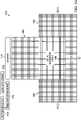
- FIG. 2 shows a headlamp reflector 200 that includes a DMD 108 and static reflectors 202, 204 and 206.
- the headlamp reflector 200 is an example of the reflector 106
- the static reflectors 202, 204 and 206 are an example of the static reflector 110.
- the area of the static reflectors 202 and 206 disposed on left and right sides of the DMD 108 is approximately equal. Accordingly, the arrangement of the static reflectors 202 and 206 may be described as symmetrical with respect to the DMD 108.
- the static reflectors 202, 204 and 206 may be provided as a monolithic unit. In other examples, the static reflectors 202, 204 and 206 and/or sub-portions thereof may be provided as separate units.
- the DMD 108 provides adaptive beam steering and shaping of the field of view by modulating incident light via the micromirrors.
- Limited beam adaptation may be provided using the static reflectors 202, 204 and 206 by modulating the light output of the light source 102 directed to the static reflectors 202, 204 and/or 206.
- area 214 of the static reflector 202 may be illuminated by a first LED
- area 216 of the static reflector 202 may be illuminated by a second LED
- light output of the first LED may differ from light output of the second LED in intensity and/or modulation to provide limited beam adaptation.
- the light source 102 may direct light to different portions of the reflector 200 from different directions. For example, in FIG. 2 , light 212 is directed to the static reflector 202 from a first direction, light 210 is directed to the static reflector 204 and the DMD 108 from a second direction, and light 208 is directed to the static reflector 206 from a third direction. An angle of reflection of the static reflectors 202, 204 and 206 and of the DMD 108 may be selected to direct light 208, 210 and 210 to the projection optics 112.
- FIG. 3 shows detail of an example of the static reflector 110 suitable for use in a headlamp reflector 106 with a DMD 108 in accordance with various embodiments.
- the static reflector 110 includes a reflective grating 302.
- the pitch angle ( ⁇ g ) of the reflective grating 302 may be about the same or greater than the angle of the mirrors of the DMD 108 in an "on" state.
- the grating pitch ( P g ) (e.g., distance between grating apices) may be larger than the pitch of the mirrors in the DMD 108.
- the pitch and angle of the reflective grating 302 may be uniform, or may vary across the static reflector 110.
- the reflective grating 302 or a reflective material may be coplanar with the DMD 108, or disposed in a plane offset from a plane corresponding to the DMD 108. In various examples, the reflective grating 302 or a reflective material may be disposed on either side of or embedded with a glass substrate.
- left and right headlamp beam overlay may cause the beam from the static reflectors 202, 204 and 206 to overlap with the image produced by the DMD 108 at some distance from the headlamps, depending upon the field of view. The overlap may reduce the effective addressable resolution on the road.
- FIG. 4 shows a headlamp reflector 400 that may reduce static reflector overlap and degradation of the effectiveness of the DMD 108.
- the headlamp reflector 400 includes a DMD 108 and static reflectors 402 and 404.
- the headlamp reflector 400 is an example of the reflector 106, and the static reflectors 402 and 404 are an example of the static reflector 110.
- the static reflector 402 is disposed on one side of the DMD 108, and the static reflector 404 is disposed below the DMD 108.
- the reflector 400 lacks a static reflector adjacent one side of the DMD 108. Accordingly, the arrangement of the static reflectors 402 and 404 may be described as asymmetrical with respect to the DMD 108.
- the static reflectors 402 and 404 may be provided as a monolithic unit. In other examples, the static reflectors 402 and 404 may be provided as separate units.
- the DMD 108 provides adaptive beam steering and shaping of the field of view by modulating incident light via the micromirrors. Limited beam adaptation may be provided using the static reflectors 402 and 404 by modulating the light output of the light source 102 directed to the static reflectors 402 and 404.
- FIGS. 5A and 5B show a headlamp reflector 500 that includes a moveable static reflector in accordance with various embodiments.
- the headlamp reflector 500 includes a DMD 108, fixed static reflectors 502, 504 and 506, moveable static reflector 508 and actuator 510.
- the headlamp reflector 500 is an embodiment of the reflector 106, and the static reflectors 502, 504, 506 and 508 are an embodiment of the static reflector 110.
- a symmetrical arrangement of the static reflectors relative to the DMD 108 is shown in that the area of the static reflectors 502 and 506 disposed on left and right sides of the DMD 108 is approximately equal.
- that relationship of the static reflectors to the DMD 108 may be asymmetrical (e.g., as shown in FIG. 4 ).
- the static reflector 508 is moveable. In FIG. 5A , the static reflector 508 is positioned to enable use of the DMD 108 to reflect light generated by the light source 102. In FIG. 5B , the static reflector 508 is positioned to disable use of the DMD 108 and to enable the static reflector 508 to reflect light generated by the light source 102.
- the static reflector 508 is coupled to the actuator 510.
- the actuator 510 may be a solenoid or other device capable of moving the static reflector 508 between at least two positions.
- the actuator is coupled to mobile reflector control circuitry 512.
- the mobile reflector control circuitry 512 monitors environmental conditions, such as temperature and/or external illumination, and controls the actuator 510 based on measurements of the environmental conditions.
- the mobile reflector control circuitry 512 may be disposed remotely from the reflector 500 and the headlamp 100.
- the mobile reflector control circuitry 512 may include or be coupled to sensors, such as temperature sensor 514 and/or illumination sensor 516, that are disposed in the reflector 500 and/or in the headlamp 100 while circuitry that processes the output of the sensors (e.g., digitizers, microcontrollers, etc.) is disposed outside of the headlamp 100 (e.g., in the engine compartment, vehicle cabin, etc.).
- the mobile reflector control circuitry 512 applies the temperature sensor 514 to measure the temperature of the DMD 108 or the temperature proximate the DMD 108. If the measured temperature does not exceed a predetermined temperature threshold (e.g., 105 degrees Celsius), then the mobile reflector control circuitry 512 may assert control to the actuator 510 to cause the actuator 510 to position the static reflector 508 as shown in FIG. 5A . If the temperature of the DMD 108 or the temperature proximate the DMD 108 exceeds the predetermined temperature threshold, as may occur in high ambient temperature conditions such as desert driving, then the mobile reflector control circuitry 512 may assert control to the actuator 510 to cause the actuator 510 to position the static reflector 508 as shown in FIG. 5B .
- a predetermined temperature threshold e.g., 105 degrees Celsius
- the mobile reflector control circuitry 512 may assert control to the actuator 510 to cause the actuator 510 to position the static reflector 508 as shown in FIG. 5A . If the level of illumination exceeds the predetermined illumination threshold (as in daylight conditions presenting high sunlight), then mobile reflector control circuitry 512 may assert control to the actuator 510 to cause the actuator 510 to position the static reflector 508 as shown in FIG. 5B .
- the default position of the static reflector 508 may be as shown in FIG. 5B , with the static reflector 508 covering the DMD 108.
- a spring coupled to the static reflector 508 may position the static reflector 508 to cover the DMD 108 in the absence of force applied by the actuator 510 to move the static reflector 508 away from the DMD 108 as in FIG. 5A .
- the DMD 108 and associated circuitry may be powered off while the static reflector 508 is positioned to cover the DMD 108.
- FIG. 6 shows a flow diagram for a method 600 for controlling the position of a moveable portion of a static reflector. Though depicted sequentially as a matter of convenience, at least some of the actions shown can be performed in a different order and/or performed in parallel. Also, some implementations may perform only some of the actions shown. In some implementations, at least some of the operations of the method 600 can be implemented by the headlamp 500.
- the temperature sensor 514 disposed in the headlamp 500 is measuring the temperature of the DMD 108 or measuring the temperature of the headlamp 500 proximate the DMD 108.
- the mobile reflector control circuitry 512 compares the output of the temperature sensor 514 to a temperature threshold value.
- the temperature threshold value represents a temperature at or below which the static reflector 508 may be positioned to allow the DMD 108 to reflect light. For example, at temperatures below 105° Celsius the static reflector 508 may be positioned to allow the DMD 108 to reflect light, while at temperatures ⁇ 105° Celsius the static reflector 508 may be positioned to cover the DMD 108 and to reflect light in place of the DMD 108.
- the mobile reflector control circuitry 512 asserts control to the actuator 510 to cause the actuator 510 to position the static reflector 508 to cover the DMD 108 as shown in FIG. 5B .
- the illumination sensor 516 disposed in or proximate to the headlamp 500 measures the intensity of illumination external to the headlamp 500.
- the mobile reflector control circuitry 512 compares the output of the illumination sensor 516 to an illumination threshold value.
- the illumination threshold value represents an illumination intensity at or below which the static reflector 508 may be positioned to allow the DMD 108 to reflect light. For example, at illumination intensities below 100,000 lux the static reflector 508 may be positioned to allow the DMD to reflect light, while at illumination intensities ⁇ 100,000 lux the static reflector 508 may be positioned to cover the DMD 108 and to reflect light in place of the DMD 108.
- the mobile reflector control circuitry 512 asserts control to the actuator 510 to cause the actuator 510 to position the static reflector 508 to cover the DMD 108 as shown in FIG. 5B .
- the mobile reflector control circuitry 512 asserts control to the actuator 510 to cause the actuator 510 to position the static reflector 508 to uncover the DMD 108 as shown in FIG. 5A .
Landscapes
- Engineering & Computer Science (AREA)
- General Engineering & Computer Science (AREA)
- Mechanical Engineering (AREA)
- Physics & Mathematics (AREA)
- Microelectronics & Electronic Packaging (AREA)
- Optics & Photonics (AREA)
- Non-Portable Lighting Devices Or Systems Thereof (AREA)
- Lighting Device Outwards From Vehicle And Optical Signal (AREA)
- Arrangement Of Elements, Cooling, Sealing, Or The Like Of Lighting Devices (AREA)
- Mechanical Light Control Or Optical Switches (AREA)
Description
- Glare-free forward illumination has become an important goal to improve night driving safety for vehicles. Automotive headlamps with patterned beams have been proposed to dynamically illuminate the field of view. In some applications, the headlamp beam pattern may be modified based on data from a variety of sources, including forward looking sensors, indicators or beacons located on the roadway, with positional or traffic data from GPS receivers, or even attitude sensors. Headlamp systems using dynamic beam adaptation potentially enable a number of applications, such as: glare-free high beams; pedestrian face masking; animal spot lighting; target painting; reflection reduction; vehicle attitude compensation; adaptive front beam steering; and projecting information on the roadway.
DE 11 2013 003050 T5 discloses such an automotive headlamp. - This invention relates to a headlamp according to the preamble of claim 1. In described examples, a headlamp includes a digital micromirror device (DMD) reflector, a light source and projection optics. The DMD reflector includes a DMD and a static reflector disposed on a plurality of sides of the DMD. The light source is disposed to illuminate the DMD reflector. The projection optics are configured to project light reflected by the DMD and light reflected by the static reflector via a same lens system. The headlamp may be an automotive headlamp.
- In another example, a headlamp includes a DMD reflector and a light source. The DMD reflector includes a DMD and a static reflector. The static reflector is disposed on a plurality of sides of the DMD. The static reflector includes a fixed portion, a mobile portion and an actuator. The actuator is configured to move the mobile portion from a first position to a second position. The light source is disposed to illuminate the DMD reflector. The headlamp may be an automotive headlamp.
- In a further example, a lamp reflector includes a DMD and a static reflector. The static reflector is disposed on a plurality of sides of the DMD. The static reflector includes a static reflective grating. The tilt angle of the static reflective grating is at least as large as a tilt angle of mirrors of the DMD.
- According to the invention, a headlamp includes a reflector module, a light source and projection optics. The reflector module includes a spatial light modulator, a static reflector, a light source and projection optics. The static reflector is disposed on a plurality of sides of the spatial light modulator. The light source is disposed to illuminate the reflector module. The projection optics are configured to project light from the spatial light modulator and light reflected by the static reflector via a same lens system. A portion of the static reflector is moveable from a first position that blocks the spatial light modulator from light exposure to a second position that exposes the spatial light modulator to light; and the headlamp further comprises an actuator coupled to the portion of the static reflector that is moveable, the actuator configured to move the portion of the static reflector that is moveable from the first position to the second position.
- The headlamp may be an automotive headlamp.
-
-
FIG. 1 shows a block diagram of an automotive headlamp in accordance with various embodiments. -
FIG. 2 shows a headlamp reflector that includes a digital micromirror device (DMD) and a static reflector. -
FIG. 3 shows detail of a static reflector suitable for use in a headlamp reflector with a DMD in accordance with various embodiments. -
FIG. 4 shows a headlamp reflector that includes a digital micromirror device (DMD) and a static reflector. -
FIGS. 5A-5B show a headlamp reflector that includes a DMD and a mobile static reflector in accordance with various embodiments. -
FIG. 6 shows a flow diagram for a method for controlling the position of a moveable portion of a static reflector. - In this description, the term "couple" or "couples" means either an indirect or direct wired or wireless connection. Thus, if a first device couples to a second device, that connection may be through a direct connection or through an indirect connection via other devices and connections.
- Some automotive headlamps provide pixel level control of the high beam using a matrix of light emitting diodes (LEDs) or using a digital micromirror device (DMD). The higher resolution of the DMD allows the DMD based headlamp to provide much finer control of the high beam profile than the LED matrix. However, the DMD is a semiconductor device and is subject to the usual limitations of semiconductor technology. For example, as with semiconductor devices generally, the temperature range over which a DMD operates is limited. To accommodate this limitation of the DMD, conventional DMD based headlamps may include thermal control systems to attempt to regulate the temperature of the DMD, or may include a backup lighting system to operate in place of the DMD should the temperature of the DMD exceed operating specifications. Both of these options can add significant cost and complexity to the headlamp. Additionally, conventional DMD based headlamps may include dedicated low-beam and/or mid-beam light lighting systems in addition to the DMD high beam system, which again add cost and complexity to the headlamp.
- Example embodiments include a DMD based automotive headlamp that is operable beyond the specified temperature range of the DMD device without use of complex temperature control systems or backup lighting systems. Embodiments also allow for low beam generation without inclusion of a dedicated low beam lighting system. The headlamps described herein include a static reflector disposed on multiple sides of the DMD. The static reflector may include a grating fixed at an angle suitable to reflect light in a desired pattern. In some examples, the static reflector is subdivided into multiple areas, and each area is illuminated by a different light source (e.g., a different LED). The light sources may be modulated to provide control of the lighting pattern produced via the static reflector.
- According to the invention, a portion of the static reflector is moveable. In a first position, the moveable portion of the static reflector is positioned in front of the DMD. Thus, in the first position, the moveable portion of the static reflector reflects light in place of the DMD (e.g., the moveable portion of the static reflector provides high beam functionality). In a second position, the moveable portion of the static reflector is positioned to allow the DMD to reflect incoming light (e.g., the DMD provides high beam functionality). Embodiments may position the moveable portion of the static reflector to provide high beam functionality based on the temperature, external light conditions, or other environmental factors that may affect the operation of the DMD.
-
FIG. 1 shows a block diagram of anautomotive headlamp 100 in accordance with various embodiments. Theheadlamp 100 includes alight source 102, areflector 106 andprojection optics 112. Thelight source 102 includes one ormore LEDs 104 that project light onto thereflector 106. Some embodiments of thelight source 102 may include light generation devices other than or in addition to LEDs. Thelight source 102 may include modulation circuitry that controls the output intensity one or more of theLEDs 104 by switching (e.g., pulse width modulating) a control signal to theLEDs 104 or by changing a drive current provided to theLEDs 104. For example, the modulation circuitry may provide individual control of each the output intensity of each of theLEDs 104. - Light generated by the
light source 102 is projected onto thereflector 106. Thereflector 106 includes aDMD 108 and astatic reflector 110. TheDMD 108 is one example of a spatial light modulator suitable for use in theheadlamp 100. Some embodiments of theheadlamp 100 may employ a liquid crystal on silicon (LCOS) device, a liquid crystal display (LCD) device, or other spatial light modulation technology in place of theDMD 108. Accordingly, the embodiments described herein encompass headlamps that employ a variety of spatial modulation technologies including DMD, LCOS, LCD, etc. - Inclusion of the
static reflector 110 in thereflector 106 provides a number of advantages. Thestatic reflector 110 increases the active area of thereflector 106, which in turn increases etendue without increasing the area of theDMD 108. With thestatic reflector 110, a wider field of view and higher brightness may be provided by increasing the size of the light source 102 (e.g., increasing the number ofLEDs 104 included in the light source 102). Thestatic reflector 110 may be disposed adjacent to at least two sides of the DMD. Embodiments of thestatic reflector 110 may include a flat mirror, a curved mirror and/or a Fresnel element that reflects light received from thelight source 102. - Light reflected by the
reflector 106 is directed to theprojection optics 112. Theprojection optics 112 may be any lens or lens system that captures the light reflected by thereflector 106 and projects the captured light away from theheadlamp 100, e.g., onto the roadway. In embodiments of theautomotive headlamp 100, a single assembly of projection optics 112 (e.g., a single lens system) receives reflected light from both theDMD 108 and thestatic reflector 110 and projects the reflected light away from theheadlamp 100. Thus, embodiments employ a single set ofprojection optics 112 for both theDMD 108 and thestatic reflector 110 rather than separate projection optics for the different reflectors as is conventional. -
FIG. 2 shows aheadlamp reflector 200 that includes aDMD 108 andstatic reflectors headlamp reflector 200 is an example of thereflector 106, and thestatic reflectors static reflector 110. The area of thestatic reflectors DMD 108 is approximately equal. Accordingly, the arrangement of thestatic reflectors DMD 108. In some examples, thestatic reflectors static reflectors - The
DMD 108 provides adaptive beam steering and shaping of the field of view by modulating incident light via the micromirrors. Limited beam adaptation may be provided using thestatic reflectors light source 102 directed to thestatic reflectors area 214 of thestatic reflector 202 may be illuminated by a first LED, andarea 216 of thestatic reflector 202 may be illuminated by a second LED, and light output of the first LED may differ from light output of the second LED in intensity and/or modulation to provide limited beam adaptation. - The
light source 102 may direct light to different portions of thereflector 200 from different directions. For example, inFIG. 2 , light 212 is directed to thestatic reflector 202 from a first direction, light 210 is directed to thestatic reflector 204 and theDMD 108 from a second direction, and light 208 is directed to thestatic reflector 206 from a third direction. An angle of reflection of thestatic reflectors DMD 108 may be selected to direct light 208, 210 and 210 to theprojection optics 112. -
FIG. 3 shows detail of an example of thestatic reflector 110 suitable for use in aheadlamp reflector 106 with aDMD 108 in accordance with various embodiments. Thestatic reflector 110 includes areflective grating 302. In some examples, the pitch angle (θg ) of thereflective grating 302 may be about the same or greater than the angle of the mirrors of theDMD 108 in an "on" state. The grating pitch (Pg ) (e.g., distance between grating apices) may be larger than the pitch of the mirrors in theDMD 108. In various examples, the pitch and angle of thereflective grating 302 may be uniform, or may vary across thestatic reflector 110. In some examples of thestatic reflector 110, thereflective grating 302 or a reflective material may be coplanar with theDMD 108, or disposed in a plane offset from a plane corresponding to theDMD 108. In various examples, thereflective grating 302 or a reflective material may be disposed on either side of or embedded with a glass substrate. - Using examples of the
headlamp reflector 200 to implement vehicular headlights, left and right headlamp beam overlay may cause the beam from thestatic reflectors DMD 108 at some distance from the headlamps, depending upon the field of view. The overlap may reduce the effective addressable resolution on the road.FIG. 4 shows aheadlamp reflector 400 that may reduce static reflector overlap and degradation of the effectiveness of theDMD 108. Theheadlamp reflector 400 includes aDMD 108 andstatic reflectors headlamp reflector 400 is an example of thereflector 106, and thestatic reflectors static reflector 110. Thestatic reflector 402 is disposed on one side of theDMD 108, and thestatic reflector 404 is disposed below theDMD 108. Thereflector 400 lacks a static reflector adjacent one side of theDMD 108. Accordingly, the arrangement of thestatic reflectors DMD 108. In some examples, thestatic reflectors static reflectors - The
DMD 108 provides adaptive beam steering and shaping of the field of view by modulating incident light via the micromirrors. Limited beam adaptation may be provided using thestatic reflectors light source 102 directed to thestatic reflectors -
FIGS. 5A and5B show aheadlamp reflector 500 that includes a moveable static reflector in accordance with various embodiments. Theheadlamp reflector 500 includes aDMD 108, fixedstatic reflectors static reflector 508 andactuator 510. Theheadlamp reflector 500 is an embodiment of thereflector 106, and thestatic reflectors static reflector 110. In the illustrated embodiment of thereflector 500, a symmetrical arrangement of the static reflectors relative to theDMD 108 is shown in that the area of thestatic reflectors DMD 108 is approximately equal. In some embodiments, that relationship of the static reflectors to theDMD 108 may be asymmetrical (e.g., as shown inFIG. 4 ). - The
static reflector 508 is moveable. InFIG. 5A , thestatic reflector 508 is positioned to enable use of theDMD 108 to reflect light generated by thelight source 102. InFIG. 5B , thestatic reflector 508 is positioned to disable use of theDMD 108 and to enable thestatic reflector 508 to reflect light generated by thelight source 102. Thestatic reflector 508 is coupled to theactuator 510. Theactuator 510 may be a solenoid or other device capable of moving thestatic reflector 508 between at least two positions. The actuator is coupled to mobilereflector control circuitry 512. The mobilereflector control circuitry 512 monitors environmental conditions, such as temperature and/or external illumination, and controls theactuator 510 based on measurements of the environmental conditions. The mobilereflector control circuitry 512, or a portion thereof, may disposed remotely from thereflector 500 and theheadlamp 100. For example, the mobilereflector control circuitry 512 may include or be coupled to sensors, such astemperature sensor 514 and/orillumination sensor 516, that are disposed in thereflector 500 and/or in theheadlamp 100 while circuitry that processes the output of the sensors (e.g., digitizers, microcontrollers, etc.) is disposed outside of the headlamp 100 (e.g., in the engine compartment, vehicle cabin, etc.). - In some examples, the mobile
reflector control circuitry 512 applies thetemperature sensor 514 to measure the temperature of theDMD 108 or the temperature proximate theDMD 108. If the measured temperature does not exceed a predetermined temperature threshold (e.g., 105 degrees Celsius), then the mobilereflector control circuitry 512 may assert control to theactuator 510 to cause theactuator 510 to position thestatic reflector 508 as shown inFIG. 5A . If the temperature of theDMD 108 or the temperature proximate theDMD 108 exceeds the predetermined temperature threshold, as may occur in high ambient temperature conditions such as desert driving, then the mobilereflector control circuitry 512 may assert control to theactuator 510 to cause theactuator 510 to position thestatic reflector 508 as shown inFIG. 5B . Similarly, if the level of illumination does not exceed a predetermined illumination threshold, then the mobilereflector control circuitry 512 may assert control to theactuator 510 to cause theactuator 510 to position thestatic reflector 508 as shown inFIG. 5A . If the level of illumination exceeds the predetermined illumination threshold (as in daylight conditions presenting high sunlight), then mobilereflector control circuitry 512 may assert control to theactuator 510 to cause theactuator 510 to position thestatic reflector 508 as shown inFIG. 5B . - In some examples of the
headlamp 100, the default position of thestatic reflector 508 may be as shown inFIG. 5B , with thestatic reflector 508 covering theDMD 108. For example, a spring coupled to thestatic reflector 508 may position thestatic reflector 508 to cover theDMD 108 in the absence of force applied by theactuator 510 to move thestatic reflector 508 away from theDMD 108 as inFIG. 5A . TheDMD 108 and associated circuitry may be powered off while thestatic reflector 508 is positioned to cover theDMD 108. -
FIG. 6 shows a flow diagram for amethod 600 for controlling the position of a moveable portion of a static reflector. Though depicted sequentially as a matter of convenience, at least some of the actions shown can be performed in a different order and/or performed in parallel. Also, some implementations may perform only some of the actions shown. In some implementations, at least some of the operations of themethod 600 can be implemented by theheadlamp 500. - In
block 602, thetemperature sensor 514 disposed in theheadlamp 500 is measuring the temperature of theDMD 108 or measuring the temperature of theheadlamp 500 proximate theDMD 108. - In
block 604, the mobilereflector control circuitry 512 compares the output of thetemperature sensor 514 to a temperature threshold value. The temperature threshold value represents a temperature at or below which thestatic reflector 508 may be positioned to allow theDMD 108 to reflect light. For example, at temperatures below 105° Celsius thestatic reflector 508 may be positioned to allow theDMD 108 to reflect light, while at temperatures ≥ 105° Celsius thestatic reflector 508 may be positioned to cover theDMD 108 and to reflect light in place of theDMD 108. - In
block 604, if the temperature measured by thetemperature sensor 514 is not less than the temperature threshold value, then inblock 606 the mobilereflector control circuitry 512 asserts control to theactuator 510 to cause theactuator 510 to position thestatic reflector 508 to cover theDMD 108 as shown inFIG. 5B . - In
block 604, if the temperature measured by thetemperature sensor 514 is less than the temperature threshold value, then inblock 608 theillumination sensor 516 disposed in or proximate to theheadlamp 500 measures the intensity of illumination external to theheadlamp 500. - In
block 610, the mobilereflector control circuitry 512 compares the output of theillumination sensor 516 to an illumination threshold value. The illumination threshold value represents an illumination intensity at or below which thestatic reflector 508 may be positioned to allow theDMD 108 to reflect light. For example, at illumination intensities below 100,000 lux thestatic reflector 508 may be positioned to allow the DMD to reflect light, while at illumination intensities ≥ 100,000 lux thestatic reflector 508 may be positioned to cover theDMD 108 and to reflect light in place of theDMD 108. - In
block 610, if the illumination measured by theillumination sensor 516 is not less than the illumination threshold value, then inblock 606 the mobilereflector control circuitry 512 asserts control to theactuator 510 to cause theactuator 510 to position thestatic reflector 508 to cover theDMD 108 as shown inFIG. 5B . - In
block 610, if the illumination measured by theillumination sensor 516 is less than the illumination threshold value, then inblock 612 the mobilereflector control circuitry 512 asserts control to theactuator 510 to cause theactuator 510 to position thestatic reflector 508 to uncover theDMD 108 as shown inFIG. 5A . - Modifications are possible in the described embodiments, and other embodiments are possible, within the scope of the claims.
Claims (4)
- A headlamp (100), comprising:a reflector module (106,200,400,500) comprising: a spatial light modulator; and a static reflector (110,202,204,206,502,504,506,508) disposed on a plurality of sides of the spatial light modulator;a light source (102) disposed to illuminate the reflector module (106,200,400,500); andprojection optics (112) configured to project light from the spatial light modulator and light reflected by the static reflector (110,202,204,206,502,504,506,508) via a same lens system, and characterized in that a portion (508) of the static reflector (502,504,506,508) is moveable from a first position that blocks the spatial light modulator from light exposure to a second position that exposes the spatial light modulator to light; and further comprising an actuator (510) coupled to the portion (508) of the static reflector (502,504,506,508) that is moveable, the actuator (510) configured to move the portion (508) of the static reflector (502,504,506,508) that is moveable from the first position to the second position.
- A headlamp according to claim 1, wherein the spatial light modulator is a DMD (108), and the static reflector (502,504,506,508) is disposed on a plurality of sides of the DMD (108); andwherein the projection optics (112) are configured to project light reflected by the DMD (108) and light reflected by the static reflector (502,504,506,508) via the same lens system;in the first position, the portion (508) of static reflector (502,504,506,508) blocks the DMD (108) from light exposure; andin the second position, the DMD (108) is exposed to light.
- A headlamp according to claim 2, wherein the static reflector (502,504,506,508) comprises one or more ofa flat mirror configured to reflect light from the light source (102) to the projection optics (112);a curved mirror configured to reflect light from the light source (102) to the projection optics (112); anda Fresnel element configured to reflect light from the light source (102) to the projection optics (112); andfurther comprising control circuitry (512) configured to:monitor temperature of the DMD (108); andmove the portion (508) of the static reflector (502,504,506,508) from the first position to the second position responsive to the temperature of the DMD (108) being less than a predetermined limit
- A headlamp according to claim 2, wherein the static reflector (502,504,506,508) comprises one or more ofa flat mirror configured to reflect light from the light source (102) to the projection optics (112);a curved mirror configured to reflect light from the light source (102) to the projection optics (112); anda Fresnel element configured to reflect light from the light source (102) to the projection optics (112); andfurther comprising control circuitry (512) configured to:monitor illumination external to the headlamp (100); andmove the portion (508) of the static reflector (502,504,506,508) from the first position to the second position responsive to the intensity of illumination external to the headlamp (100) being less than a predetermined limit.
Applications Claiming Priority (3)
| Application Number | Priority Date | Filing Date | Title |
|---|---|---|---|
| US201762469767P | 2017-03-10 | 2017-03-10 | |
| US15/811,752 US10317032B2 (en) | 2017-03-10 | 2017-11-14 | Headlamp with digital micromirror device and static reflector |
| PCT/US2018/021258 WO2018165236A1 (en) | 2017-03-10 | 2018-03-07 | Headlamp with digital micromirror device and static reflector |
Publications (3)
| Publication Number | Publication Date |
|---|---|
| EP3592602A1 EP3592602A1 (en) | 2020-01-15 |
| EP3592602A4 EP3592602A4 (en) | 2020-11-25 |
| EP3592602B1 true EP3592602B1 (en) | 2022-04-27 |
Family
ID=63444974
Family Applications (1)
| Application Number | Title | Priority Date | Filing Date |
|---|---|---|---|
| EP18764743.3A Active EP3592602B1 (en) | 2017-03-10 | 2018-03-07 | Headlamp with digital micromirror device and static reflector |
Country Status (5)
| Country | Link |
|---|---|
| US (1) | US10317032B2 (en) |
| EP (1) | EP3592602B1 (en) |
| JP (2) | JP7157296B2 (en) |
| CN (1) | CN110382295B (en) |
| WO (1) | WO2018165236A1 (en) |
Families Citing this family (2)
| Publication number | Priority date | Publication date | Assignee | Title |
|---|---|---|---|---|
| DE102019123936A1 (en) * | 2019-09-06 | 2021-03-11 | Automotive Lighting Reutlingen Gmbh | Lighting device and projection module for such a lighting device |
| US11524625B2 (en) | 2019-12-12 | 2022-12-13 | Texas Instruments Incorporated | Adaptive vehicle headlight |
Family Cites Families (29)
| Publication number | Priority date | Publication date | Assignee | Title |
|---|---|---|---|---|
| US1370255A (en) * | 1921-03-01 | Besxectob | ||
| JPH1039772A (en) * | 1996-07-29 | 1998-02-13 | Mitsubishi Electric Corp | Projection type liquid crystal display |
| DE19907943C2 (en) * | 1999-02-25 | 2001-02-22 | Bosch Gmbh Robert | Motor vehicle headlight with a deflection device for changing the direction of at least part of a light beam |
| US6497503B1 (en) | 2001-06-21 | 2002-12-24 | Ford Global Technologies, Inc. | Headlamp system with selectable beam pattern |
| DE102006047837A1 (en) * | 2006-10-10 | 2008-04-17 | Volkswagen Ag | Motor vehicle headlight, has parabolic reflector, whose focus point is brought in combination with light source for forming driving light, where reflector is focused and defocused for forming day driving light opposite to light source |
| JP4695112B2 (en) * | 2007-03-26 | 2011-06-08 | 株式会社小糸製作所 | Vehicle headlamp lamp unit |
| WO2009026223A2 (en) * | 2007-08-16 | 2009-02-26 | Gentex Corporation | Vehicle rearview assembly including a display for displaying video captured by a camera and user instructions |
| JP2009095876A (en) * | 2007-10-18 | 2009-05-07 | Olympus Corp | Laser processing apparatus, laser processing method, and laser processing program |
| US7826135B2 (en) * | 2008-10-20 | 2010-11-02 | Texas Instruments Incorporated | Screen film for light projection brightness enhancement |
| JP5418760B2 (en) * | 2009-01-28 | 2014-02-19 | スタンレー電気株式会社 | Vehicle lighting |
| US8554049B2 (en) * | 2011-12-28 | 2013-10-08 | United Video Properties, Inc. | Systems and methods for synchronizing playback at multiple locations |
| JP5894804B2 (en) * | 2012-01-12 | 2016-03-30 | 株式会社小糸製作所 | Vehicle lighting |
| CN104412035B (en) * | 2012-06-29 | 2016-10-19 | 株式会社小糸制作所 | Lamps apparatus for vehicle and control method thereof |
| JP5948194B2 (en) * | 2012-09-13 | 2016-07-06 | 株式会社小糸製作所 | Vehicle lamp control method and vehicle lamp |
| US9094700B2 (en) * | 2013-03-14 | 2015-07-28 | Intel Corporation | Dynamically implementing an image protection policy |
| JP6132684B2 (en) * | 2013-07-10 | 2017-05-24 | 株式会社小糸製作所 | Vehicle lighting |
| US9658447B2 (en) | 2013-12-09 | 2017-05-23 | Texas Instruments Incorporated | Multiple illumination sources for DMD lighting apparatus and methods |
| JP6274891B2 (en) * | 2014-02-03 | 2018-02-07 | 株式会社小糸製作所 | Vehicle lighting |
| US20150285458A1 (en) | 2014-04-08 | 2015-10-08 | Ford Global Technologies, Llc | Vehicle headlamp system |
| JP2016009608A (en) | 2014-06-25 | 2016-01-18 | パナソニックIpマネジメント株式会社 | Lighting device and car equipped with it |
| US10066799B2 (en) | 2014-06-26 | 2018-09-04 | Texas Instruments Incorporated | Pixelated projection for automotive headlamp |
| US9869442B2 (en) | 2014-06-26 | 2018-01-16 | Texas Instruments Incorporated | Hybrid illumination system having a blue laser diode, dichroic mirror and yellow transmissive phosphor converter for generating white light |
| DE102014221389A1 (en) * | 2014-10-21 | 2016-04-21 | Automotive Lighting Reutlingen Gmbh | Light module of a lighting device and lighting device with such a light module |
| JP2016115582A (en) * | 2014-12-16 | 2016-06-23 | 株式会社小糸製作所 | Vehicular lighting unit with light distribution device |
| DE102015103179A1 (en) * | 2015-03-05 | 2016-10-20 | Hella Kgaa Hueck & Co. | Lighting device for vehicles |
| JP6504886B2 (en) * | 2015-04-03 | 2019-04-24 | 株式会社小糸製作所 | Vehicle lamp |
| US10436409B2 (en) | 2015-05-28 | 2019-10-08 | Texas Instruments Incorporated | Methods and apparatus for light efficient programmable headlamp with anamorphic optics |
| AT517294A1 (en) * | 2015-06-09 | 2016-12-15 | Zkw Group Gmbh | Headlights for vehicles |
| WO2017056469A1 (en) * | 2015-09-29 | 2017-04-06 | パナソニックIpマネジメント株式会社 | Light source device and projection device |
-
2017
- 2017-11-14 US US15/811,752 patent/US10317032B2/en active Active
-
2018
- 2018-03-07 EP EP18764743.3A patent/EP3592602B1/en active Active
- 2018-03-07 JP JP2019549455A patent/JP7157296B2/en active Active
- 2018-03-07 WO PCT/US2018/021258 patent/WO2018165236A1/en not_active Ceased
- 2018-03-07 CN CN201880016505.3A patent/CN110382295B/en active Active
-
2022
- 2022-09-12 JP JP2022144456A patent/JP7616515B2/en active Active
Also Published As
| Publication number | Publication date |
|---|---|
| US20180259149A1 (en) | 2018-09-13 |
| CN110382295A (en) | 2019-10-25 |
| JP7157296B2 (en) | 2022-10-20 |
| US10317032B2 (en) | 2019-06-11 |
| JP2022174212A (en) | 2022-11-22 |
| EP3592602A4 (en) | 2020-11-25 |
| JP2020511743A (en) | 2020-04-16 |
| CN110382295B (en) | 2022-11-25 |
| EP3592602A1 (en) | 2020-01-15 |
| JP7616515B2 (en) | 2025-01-17 |
| WO2018165236A1 (en) | 2018-09-13 |
Similar Documents
| Publication | Publication Date | Title |
|---|---|---|
| US11904759B1 (en) | Adaptive headlamp system for vehicle | |
| CN108343925B (en) | Vehicle headlight | |
| US10286835B2 (en) | Vehicle headlight device and vehicle | |
| US20210341123A1 (en) | Vehicle lamp | |
| US20140029282A1 (en) | Adaptive lighting system for an automobile vehicle | |
| TW202212731A (en) | Vehicle external illumination device | |
| JP7616515B2 (en) | Headlamp using digital micromirror device and static reflector | |
| CN115899609A (en) | Adaptive light source with spatial light modulator | |
| US11209144B2 (en) | Low cost projection system | |
| US11732859B2 (en) | Vehicle headlamp | |
| TWI588043B (en) | Vehicle Headlight Apparatus And Vehicle | |
| EP4497633B1 (en) | Vehicular lamp system, light distribution control device, and light distribution control method | |
| US10781988B2 (en) | Vehicular lamp | |
| JP7472327B2 (en) | ADAPTIVE HEADLAMP SYSTEM FOR A VEHICLE - Patent application | |
| US20200240609A1 (en) | Vehicle lighting device with a digital micromirror device | |
| JP2024101384A (en) | Vehicle lighting system, control device, light distribution control method and program |
Legal Events
| Date | Code | Title | Description |
|---|---|---|---|
| STAA | Information on the status of an ep patent application or granted ep patent |
Free format text: STATUS: THE INTERNATIONAL PUBLICATION HAS BEEN MADE |
|
| PUAI | Public reference made under article 153(3) epc to a published international application that has entered the european phase |
Free format text: ORIGINAL CODE: 0009012 |
|
| STAA | Information on the status of an ep patent application or granted ep patent |
Free format text: STATUS: REQUEST FOR EXAMINATION WAS MADE |
|
| 17P | Request for examination filed |
Effective date: 20191010 |
|
| AK | Designated contracting states |
Kind code of ref document: A1 Designated state(s): AL AT BE BG CH CY CZ DE DK EE ES FI FR GB GR HR HU IE IS IT LI LT LU LV MC MK MT NL NO PL PT RO RS SE SI SK SM TR |
|
| AX | Request for extension of the european patent |
Extension state: BA ME |
|
| DAV | Request for validation of the european patent (deleted) | ||
| DAX | Request for extension of the european patent (deleted) | ||
| RIC1 | Information provided on ipc code assigned before grant |
Ipc: B60Q 1/14 20060101ALI20200701BHEP Ipc: B60Q 1/00 20060101ALI20200701BHEP Ipc: F21V 7/00 20060101ALI20200701BHEP Ipc: F21S 41/663 20180101ALI20200701BHEP Ipc: F21S 41/675 20180101ALI20200701BHEP Ipc: B60Q 1/08 20060101ALI20200701BHEP Ipc: F21S 41/33 20180101ALI20200701BHEP Ipc: B60Q 1/04 20060101AFI20200701BHEP Ipc: F21S 41/32 20180101ALI20200701BHEP Ipc: F21S 41/141 20180101ALI20200701BHEP Ipc: F21S 41/36 20180101ALI20200701BHEP Ipc: F21S 45/10 20180101ALI20200701BHEP |
|
| A4 | Supplementary search report drawn up and despatched |
Effective date: 20201026 |
|
| RIC1 | Information provided on ipc code assigned before grant |
Ipc: F21V 7/00 20060101ALI20201020BHEP Ipc: F21S 41/663 20180101ALI20201020BHEP Ipc: B60Q 1/14 20060101ALI20201020BHEP Ipc: B60Q 1/04 20060101AFI20201020BHEP Ipc: F21S 41/33 20180101ALI20201020BHEP Ipc: F21S 41/32 20180101ALI20201020BHEP Ipc: F21S 41/141 20180101ALI20201020BHEP Ipc: B60Q 1/08 20060101ALI20201020BHEP Ipc: F21S 41/675 20180101ALI20201020BHEP Ipc: F21S 41/36 20180101ALI20201020BHEP Ipc: B60Q 1/00 20060101ALI20201020BHEP Ipc: F21S 45/10 20180101ALI20201020BHEP |
|
| GRAP | Despatch of communication of intention to grant a patent |
Free format text: ORIGINAL CODE: EPIDOSNIGR1 |
|
| STAA | Information on the status of an ep patent application or granted ep patent |
Free format text: STATUS: GRANT OF PATENT IS INTENDED |
|
| INTG | Intention to grant announced |
Effective date: 20211116 |
|
| GRAS | Grant fee paid |
Free format text: ORIGINAL CODE: EPIDOSNIGR3 |
|
| GRAA | (expected) grant |
Free format text: ORIGINAL CODE: 0009210 |
|
| STAA | Information on the status of an ep patent application or granted ep patent |
Free format text: STATUS: THE PATENT HAS BEEN GRANTED |
|
| AK | Designated contracting states |
Kind code of ref document: B1 Designated state(s): AL AT BE BG CH CY CZ DE DK EE ES FI FR GB GR HR HU IE IS IT LI LT LU LV MC MK MT NL NO PL PT RO RS SE SI SK SM TR |
|
| REG | Reference to a national code |
Ref country code: GB Ref legal event code: FG4D |
|
| REG | Reference to a national code |
Ref country code: CH Ref legal event code: EP |
|
| REG | Reference to a national code |
Ref country code: DE Ref legal event code: R096 Ref document number: 602018034567 Country of ref document: DE |
|
| REG | Reference to a national code |
Ref country code: AT Ref legal event code: REF Ref document number: 1486707 Country of ref document: AT Kind code of ref document: T Effective date: 20220515 |
|
| REG | Reference to a national code |
Ref country code: IE Ref legal event code: FG4D |
|
| REG | Reference to a national code |
Ref country code: LT Ref legal event code: MG9D |
|
| REG | Reference to a national code |
Ref country code: NL Ref legal event code: MP Effective date: 20220427 |
|
| REG | Reference to a national code |
Ref country code: AT Ref legal event code: MK05 Ref document number: 1486707 Country of ref document: AT Kind code of ref document: T Effective date: 20220427 |
|
| PG25 | Lapsed in a contracting state [announced via postgrant information from national office to epo] |
Ref country code: NL Free format text: LAPSE BECAUSE OF FAILURE TO SUBMIT A TRANSLATION OF THE DESCRIPTION OR TO PAY THE FEE WITHIN THE PRESCRIBED TIME-LIMIT Effective date: 20220427 |
|
| PG25 | Lapsed in a contracting state [announced via postgrant information from national office to epo] |
Ref country code: SE Free format text: LAPSE BECAUSE OF FAILURE TO SUBMIT A TRANSLATION OF THE DESCRIPTION OR TO PAY THE FEE WITHIN THE PRESCRIBED TIME-LIMIT Effective date: 20220427 Ref country code: PT Free format text: LAPSE BECAUSE OF FAILURE TO SUBMIT A TRANSLATION OF THE DESCRIPTION OR TO PAY THE FEE WITHIN THE PRESCRIBED TIME-LIMIT Effective date: 20220829 Ref country code: NO Free format text: LAPSE BECAUSE OF FAILURE TO SUBMIT A TRANSLATION OF THE DESCRIPTION OR TO PAY THE FEE WITHIN THE PRESCRIBED TIME-LIMIT Effective date: 20220727 Ref country code: LT Free format text: LAPSE BECAUSE OF FAILURE TO SUBMIT A TRANSLATION OF THE DESCRIPTION OR TO PAY THE FEE WITHIN THE PRESCRIBED TIME-LIMIT Effective date: 20220427 Ref country code: HR Free format text: LAPSE BECAUSE OF FAILURE TO SUBMIT A TRANSLATION OF THE DESCRIPTION OR TO PAY THE FEE WITHIN THE PRESCRIBED TIME-LIMIT Effective date: 20220427 Ref country code: GR Free format text: LAPSE BECAUSE OF FAILURE TO SUBMIT A TRANSLATION OF THE DESCRIPTION OR TO PAY THE FEE WITHIN THE PRESCRIBED TIME-LIMIT Effective date: 20220728 Ref country code: FI Free format text: LAPSE BECAUSE OF FAILURE TO SUBMIT A TRANSLATION OF THE DESCRIPTION OR TO PAY THE FEE WITHIN THE PRESCRIBED TIME-LIMIT Effective date: 20220427 Ref country code: ES Free format text: LAPSE BECAUSE OF FAILURE TO SUBMIT A TRANSLATION OF THE DESCRIPTION OR TO PAY THE FEE WITHIN THE PRESCRIBED TIME-LIMIT Effective date: 20220427 Ref country code: BG Free format text: LAPSE BECAUSE OF FAILURE TO SUBMIT A TRANSLATION OF THE DESCRIPTION OR TO PAY THE FEE WITHIN THE PRESCRIBED TIME-LIMIT Effective date: 20220727 Ref country code: AT Free format text: LAPSE BECAUSE OF FAILURE TO SUBMIT A TRANSLATION OF THE DESCRIPTION OR TO PAY THE FEE WITHIN THE PRESCRIBED TIME-LIMIT Effective date: 20220427 |
|
| PG25 | Lapsed in a contracting state [announced via postgrant information from national office to epo] |
Ref country code: RS Free format text: LAPSE BECAUSE OF FAILURE TO SUBMIT A TRANSLATION OF THE DESCRIPTION OR TO PAY THE FEE WITHIN THE PRESCRIBED TIME-LIMIT Effective date: 20220427 Ref country code: PL Free format text: LAPSE BECAUSE OF FAILURE TO SUBMIT A TRANSLATION OF THE DESCRIPTION OR TO PAY THE FEE WITHIN THE PRESCRIBED TIME-LIMIT Effective date: 20220427 Ref country code: LV Free format text: LAPSE BECAUSE OF FAILURE TO SUBMIT A TRANSLATION OF THE DESCRIPTION OR TO PAY THE FEE WITHIN THE PRESCRIBED TIME-LIMIT Effective date: 20220427 Ref country code: IS Free format text: LAPSE BECAUSE OF FAILURE TO SUBMIT A TRANSLATION OF THE DESCRIPTION OR TO PAY THE FEE WITHIN THE PRESCRIBED TIME-LIMIT Effective date: 20220827 |
|
| REG | Reference to a national code |
Ref country code: DE Ref legal event code: R097 Ref document number: 602018034567 Country of ref document: DE |
|
| PG25 | Lapsed in a contracting state [announced via postgrant information from national office to epo] |
Ref country code: SM Free format text: LAPSE BECAUSE OF FAILURE TO SUBMIT A TRANSLATION OF THE DESCRIPTION OR TO PAY THE FEE WITHIN THE PRESCRIBED TIME-LIMIT Effective date: 20220427 Ref country code: SK Free format text: LAPSE BECAUSE OF FAILURE TO SUBMIT A TRANSLATION OF THE DESCRIPTION OR TO PAY THE FEE WITHIN THE PRESCRIBED TIME-LIMIT Effective date: 20220427 Ref country code: RO Free format text: LAPSE BECAUSE OF FAILURE TO SUBMIT A TRANSLATION OF THE DESCRIPTION OR TO PAY THE FEE WITHIN THE PRESCRIBED TIME-LIMIT Effective date: 20220427 Ref country code: EE Free format text: LAPSE BECAUSE OF FAILURE TO SUBMIT A TRANSLATION OF THE DESCRIPTION OR TO PAY THE FEE WITHIN THE PRESCRIBED TIME-LIMIT Effective date: 20220427 Ref country code: DK Free format text: LAPSE BECAUSE OF FAILURE TO SUBMIT A TRANSLATION OF THE DESCRIPTION OR TO PAY THE FEE WITHIN THE PRESCRIBED TIME-LIMIT Effective date: 20220427 Ref country code: CZ Free format text: LAPSE BECAUSE OF FAILURE TO SUBMIT A TRANSLATION OF THE DESCRIPTION OR TO PAY THE FEE WITHIN THE PRESCRIBED TIME-LIMIT Effective date: 20220427 |
|
| PLBE | No opposition filed within time limit |
Free format text: ORIGINAL CODE: 0009261 |
|
| STAA | Information on the status of an ep patent application or granted ep patent |
Free format text: STATUS: NO OPPOSITION FILED WITHIN TIME LIMIT |
|
| PG25 | Lapsed in a contracting state [announced via postgrant information from national office to epo] |
Ref country code: AL Free format text: LAPSE BECAUSE OF FAILURE TO SUBMIT A TRANSLATION OF THE DESCRIPTION OR TO PAY THE FEE WITHIN THE PRESCRIBED TIME-LIMIT Effective date: 20220427 |
|
| 26N | No opposition filed |
Effective date: 20230130 |
|
| PG25 | Lapsed in a contracting state [announced via postgrant information from national office to epo] |
Ref country code: SI Free format text: LAPSE BECAUSE OF FAILURE TO SUBMIT A TRANSLATION OF THE DESCRIPTION OR TO PAY THE FEE WITHIN THE PRESCRIBED TIME-LIMIT Effective date: 20220427 |
|
| P01 | Opt-out of the competence of the unified patent court (upc) registered |
Effective date: 20230523 |
|
| PG25 | Lapsed in a contracting state [announced via postgrant information from national office to epo] |
Ref country code: MC Free format text: LAPSE BECAUSE OF FAILURE TO SUBMIT A TRANSLATION OF THE DESCRIPTION OR TO PAY THE FEE WITHIN THE PRESCRIBED TIME-LIMIT Effective date: 20220427 |
|
| REG | Reference to a national code |
Ref country code: CH Ref legal event code: PL |
|
| REG | Reference to a national code |
Ref country code: BE Ref legal event code: MM Effective date: 20230331 |
|
| PG25 | Lapsed in a contracting state [announced via postgrant information from national office to epo] |
Ref country code: LU Free format text: LAPSE BECAUSE OF NON-PAYMENT OF DUE FEES Effective date: 20230307 |
|
| REG | Reference to a national code |
Ref country code: IE Ref legal event code: MM4A |
|
| PG25 | Lapsed in a contracting state [announced via postgrant information from national office to epo] |
Ref country code: LI Free format text: LAPSE BECAUSE OF NON-PAYMENT OF DUE FEES Effective date: 20230331 Ref country code: IT Free format text: LAPSE BECAUSE OF FAILURE TO SUBMIT A TRANSLATION OF THE DESCRIPTION OR TO PAY THE FEE WITHIN THE PRESCRIBED TIME-LIMIT Effective date: 20220427 Ref country code: IE Free format text: LAPSE BECAUSE OF NON-PAYMENT OF DUE FEES Effective date: 20230307 Ref country code: CH Free format text: LAPSE BECAUSE OF NON-PAYMENT OF DUE FEES Effective date: 20230331 |
|
| PG25 | Lapsed in a contracting state [announced via postgrant information from national office to epo] |
Ref country code: BE Free format text: LAPSE BECAUSE OF NON-PAYMENT OF DUE FEES Effective date: 20230331 |
|
| PG25 | Lapsed in a contracting state [announced via postgrant information from national office to epo] |
Ref country code: BG Free format text: LAPSE BECAUSE OF FAILURE TO SUBMIT A TRANSLATION OF THE DESCRIPTION OR TO PAY THE FEE WITHIN THE PRESCRIBED TIME-LIMIT Effective date: 20220427 |
|
| PG25 | Lapsed in a contracting state [announced via postgrant information from national office to epo] |
Ref country code: BG Free format text: LAPSE BECAUSE OF FAILURE TO SUBMIT A TRANSLATION OF THE DESCRIPTION OR TO PAY THE FEE WITHIN THE PRESCRIBED TIME-LIMIT Effective date: 20220427 |
|
| PG25 | Lapsed in a contracting state [announced via postgrant information from national office to epo] |
Ref country code: CY Free format text: LAPSE BECAUSE OF FAILURE TO SUBMIT A TRANSLATION OF THE DESCRIPTION OR TO PAY THE FEE WITHIN THE PRESCRIBED TIME-LIMIT; INVALID AB INITIO Effective date: 20180307 |
|
| PG25 | Lapsed in a contracting state [announced via postgrant information from national office to epo] |
Ref country code: HU Free format text: LAPSE BECAUSE OF FAILURE TO SUBMIT A TRANSLATION OF THE DESCRIPTION OR TO PAY THE FEE WITHIN THE PRESCRIBED TIME-LIMIT; INVALID AB INITIO Effective date: 20180307 |
|
| PG25 | Lapsed in a contracting state [announced via postgrant information from national office to epo] |
Ref country code: TR Free format text: LAPSE BECAUSE OF FAILURE TO SUBMIT A TRANSLATION OF THE DESCRIPTION OR TO PAY THE FEE WITHIN THE PRESCRIBED TIME-LIMIT Effective date: 20220427 |
|
| PGFP | Annual fee paid to national office [announced via postgrant information from national office to epo] |
Ref country code: GB Payment date: 20260219 Year of fee payment: 9 |
|
| PGFP | Annual fee paid to national office [announced via postgrant information from national office to epo] |
Ref country code: DE Payment date: 20260219 Year of fee payment: 9 |
|
| PGFP | Annual fee paid to national office [announced via postgrant information from national office to epo] |
Ref country code: FR Payment date: 20260220 Year of fee payment: 9 |