EP3592307B1 - Gelenkstabilisierungsvorrichtung, insbesondere für das patellofemorale gelenk - Google Patents
Gelenkstabilisierungsvorrichtung, insbesondere für das patellofemorale gelenk Download PDFInfo
- Publication number
- EP3592307B1 EP3592307B1 EP18716340.7A EP18716340A EP3592307B1 EP 3592307 B1 EP3592307 B1 EP 3592307B1 EP 18716340 A EP18716340 A EP 18716340A EP 3592307 B1 EP3592307 B1 EP 3592307B1
- Authority
- EP
- European Patent Office
- Prior art keywords
- fact
- traction
- sustaining
- directing
- extremity
- Prior art date
- Legal status (The legal status is an assumption and is not a legal conclusion. Google has not performed a legal analysis and makes no representation as to the accuracy of the status listed.)
- Active
Links
Images

Classifications
-
- A—HUMAN NECESSITIES
- A61—MEDICAL OR VETERINARY SCIENCE; HYGIENE
- A61F—FILTERS IMPLANTABLE INTO BLOOD VESSELS; PROSTHESES; DEVICES PROVIDING PATENCY TO, OR PREVENTING COLLAPSING OF, TUBULAR STRUCTURES OF THE BODY, e.g. STENTS; ORTHOPAEDIC, NURSING OR CONTRACEPTIVE DEVICES; FOMENTATION; TREATMENT OR PROTECTION OF EYES OR EARS; BANDAGES, DRESSINGS OR ABSORBENT PADS; FIRST-AID KITS
- A61F5/00—Orthopaedic methods or devices for non-surgical treatment of bones or joints; Nursing devices ; Anti-rape devices
- A61F5/01—Orthopaedic devices, e.g. long-term immobilising or pressure directing devices for treating broken or deformed bones such as splints, casts or braces
- A61F5/0102—Orthopaedic devices, e.g. long-term immobilising or pressure directing devices for treating broken or deformed bones such as splints, casts or braces specially adapted for correcting deformities of the limbs or for supporting them; Ortheses, e.g. with articulations
- A61F5/0104—Orthopaedic devices, e.g. long-term immobilising or pressure directing devices for treating broken or deformed bones such as splints, casts or braces specially adapted for correcting deformities of the limbs or for supporting them; Ortheses, e.g. with articulations without articulation
- A61F5/0106—Orthopaedic devices, e.g. long-term immobilising or pressure directing devices for treating broken or deformed bones such as splints, casts or braces specially adapted for correcting deformities of the limbs or for supporting them; Ortheses, e.g. with articulations without articulation for the knees
- A61F5/0109—Sleeve-like structures
-
- A—HUMAN NECESSITIES
- A61—MEDICAL OR VETERINARY SCIENCE; HYGIENE
- A61F—FILTERS IMPLANTABLE INTO BLOOD VESSELS; PROSTHESES; DEVICES PROVIDING PATENCY TO, OR PREVENTING COLLAPSING OF, TUBULAR STRUCTURES OF THE BODY, e.g. STENTS; ORTHOPAEDIC, NURSING OR CONTRACEPTIVE DEVICES; FOMENTATION; TREATMENT OR PROTECTION OF EYES OR EARS; BANDAGES, DRESSINGS OR ABSORBENT PADS; FIRST-AID KITS
- A61F5/00—Orthopaedic methods or devices for non-surgical treatment of bones or joints; Nursing devices ; Anti-rape devices
- A61F5/01—Orthopaedic devices, e.g. long-term immobilising or pressure directing devices for treating broken or deformed bones such as splints, casts or braces
- A61F5/0102—Orthopaedic devices, e.g. long-term immobilising or pressure directing devices for treating broken or deformed bones such as splints, casts or braces specially adapted for correcting deformities of the limbs or for supporting them; Ortheses, e.g. with articulations
- A61F5/0104—Orthopaedic devices, e.g. long-term immobilising or pressure directing devices for treating broken or deformed bones such as splints, casts or braces specially adapted for correcting deformities of the limbs or for supporting them; Ortheses, e.g. with articulations without articulation
- A61F5/0106—Orthopaedic devices, e.g. long-term immobilising or pressure directing devices for treating broken or deformed bones such as splints, casts or braces specially adapted for correcting deformities of the limbs or for supporting them; Ortheses, e.g. with articulations without articulation for the knees
-
- A—HUMAN NECESSITIES
- A41—WEARING APPAREL
- A41D—OUTERWEAR; PROTECTIVE GARMENTS; ACCESSORIES
- A41D1/00—Garments
- A41D1/06—Trousers
-
- A—HUMAN NECESSITIES
- A41—WEARING APPAREL
- A41D—OUTERWEAR; PROTECTIVE GARMENTS; ACCESSORIES
- A41D27/00—Details of garments or of their making
-
- A—HUMAN NECESSITIES
- A41—WEARING APPAREL
- A41D—OUTERWEAR; PROTECTIVE GARMENTS; ACCESSORIES
- A41D2400/00—Functions or special features of garments
- A41D2400/32—Therapeutic use
Definitions
- the present invention relates to a joint stabilization device, particularly for the patellofemoral joint.
- knee pads joint stabilization devices, so-called knee pads, in order to give stability to the knee joints both during sports activities, such as e.g. running, and following surgery or traumatic lesions in which the healing process requires keeping the knee and its surrounding joints in a predefined position.
- known knee pads comprise a tubular element made of elastic material and wearable by a patient at the patellar portion.
- the tubular element is generally provided with a front through hole which, in the wearing configuration, is adapted to accommodate at least part of the patient's patella, blocking it in the respective joint seat.
- this type of knee pad has many drawbacks, particularly related to the discomfort caused to the patient by the prolonged use of same.
- the shape of the knee pad besides being a cause of discomfort, causes muscular stress linked to the overheating of the underlying tissue wrapped in the tubular element and, at the same time, causes an increase in inflammatory conditions, considerably prolonging the healing times.
- a second type of knee pad which comprises the tubular element and support means of reticular conformation associated with the latter, and positionable at the patellar portion.
- the reticular conformation of the support means is adapted to allow the dispersion of energy and shock absorption in order to relieve the pain felt during muscle activity, in case of intense physical effort, as well as from inflammatory or post-operative conditions.
- This knee pad also has the tubular element and, furthermore, a patella sustaining element associated with the tubular element itself.
- the sustaining element has an elongated substantially C-shaped conformation having the extremities associated with respective traction elements adapted to retain the patella in a predefined position.
- the sustaining element can be positioned sideways to the patella in such a way as to surround it at least partly.
- the traction elements are made of inextensible material and the traction force exerted by these on the patella is variable according to the fastening to the fastening means.
- the fastening means comprise two portions of Velcro aligned the one with the other and arranged on a portion of the tubular element opposite with respect to the sustaining element.
- the traction means are associable with the fastening means and, depending on the predefined position to be obtained, the traction exerted by the traction elements on the patella can be adjusted.
- the position of the sustaining element is variable according to the traction exerted by the traction elements on the same.
- the shape of the tubular element causes the overheating of the muscles surrounding the patella, increasing the inflammatory condition and prolonging recovery and healing times.
- the main aim of the present invention is to provide a joint stabilization device, particularly for the patellofemoral joint, which allows stimulating the muscles surrounding the patella from a neuromuscular point of view, considerably reducing recovery and healing times.
- Another object of the present invention is to provide a joint stabilization device, particularly for the patellofemoral joint, which allows modulating the patella position to be obtained according to the patient's needs.
- Another object of the present invention is to provide a joint stabilization device, particularly for the patellofemoral joint, which allows overcoming the aforementioned drawbacks of the prior art within the scope of a simple, rational, easy, efficient to use and cost-effective solution.
- the present joint stabilization device particularly for the patellofemoral joint, having the characteristics of claim 1.
- reference numeral 1 globally indicates a joint stabilization device, particularly for the patellofemoral joint.
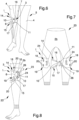
- the device 1 comprises support means 2a, 2b positionable at the patellar portion 3 of a leg 4 of a patient 5.
- the support means 2a, 2b comprise a band element 2a enveloping around the patellar portion 3.
- the band element 2a is re-closable to wrap the knee 6 by interposition of closing means, not shown in detail in the figures.
- the band element 2a in extended configuration, has four two-by-two parallel and opposite sides.
- the parallel sides have a semi-circular shaped portion and are adapted to overlap when the band element 2a is wrapped around the patellar portion 3.
- Each semi-circular shaped portion when arranged adjacent to each other, defines a housing seat 25 of the patella 6.
- the closing means are of the mechanical type, such as e.g. Velcro.
- the support means 2a, 2b have a reticular conformation adapted to cushion the impacts suffered by the patient 5 and to return the accumulated kinetic energy returning it to the joints in such a way as to support the latter during the movement of same.
- the support means 2a, 2b are of the type of a ribbon-like element made of plasticized material and having at least one adhesive face.
- the aforementioned ribbon-like element is of the type of a commonly used patch, or alternatively a taping patch.
- the band element 2a is made of a breathable elastic material.
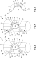
- the device 1 comprises a sustaining element 7 of elongated shape, having a first extremity 8 and a second extremity 9 opposite to each other.
- the sustaining element 7 is made in a single monolithic body.
- the sustaining element 7 is associated with the support means 2a, 2b and positionable laterally to the patella 6 of the patient 5.
- the device 1 is manufactured with the sustaining element 7 locked together with the support means 2a, 2b.
- the sustaining element 7 is associated on top of the support means 2a, 2b.
- the sustaining element 7 comprises a first concave face 10 and a second convex face 11 opposite to the first face 10 and in which the first face 10 surrounds at least partly the patella 6.
- the sustaining element 7 has a substantially C-shaped configuration and laterally surrounds the patella 6.
- the sustaining element 7 adheres to the patella 6 without leaving gaps between them; this means that the sustaining element 7 has an anatomical conformation with a profile which is substantially complementary to the lateral features of the patella 6 which enables it to fully adhere to the latter.
- the device 1 comprises at least one housing element 26 of the sustaining element 7.
- the housing element 26 is of the type of a hollow tubular element.
- the tubular element 26 is associated with the support means 2a, 2b by interposition of fastening elements of the type of Velcro or the like.
- tubular element 26 is manufactured together with the sustaining element 7 and therefore associated with the support means 2a, 2b in an irremovable way.
- the sustaining element 7 comprises transpiration means 12 adapted to allow the passage of air between the first face 10 and the second face 11.
- the transpiration means 12 comprise a plurality of through ventilation ducts 12 made on the sustaining element 7.
- the ventilation ducts 12 are adapted to allow the continuous passage of air and, therefore, a homogeneous thermoregulation of the joint tissues below the device 1.
- the transpiration means 12 comprise at least one honeycomb structure associated with the sustaining element 7.
- the transpiration means 12 are locked together with the sustaining element 7; in other words, the sustaining element 7 includes the honeycombshaped portion.
- the device 1 comprises a contact edge 13 associated with the first face 10 which, in the predefined position, abuts the patella 6 of the patient 5.
- the contact edge 13 is preferably made of flexible material adapted to increase the wearing comfort of the device 1.
- the device 1 comprises a first traction element 14 and a second traction element 15 associated with the first extremity 8 and with the second extremity 9 respectively.
- the traction elements 14, 15 comprise at least two traction bands 14 I , 14 II , 15 I , 15 II intertwined with each other.
- such traction bands 14 I , 14 II , 15 I , 15 II are made at least partly of extensible material; this means that, when subjected to tensile stress, they are subjected to an elastic deformation which is proportionate to the applied force.
- the extensibility of the traction bands 14 I , 14 II , 15 I , 15 II allows the neuromuscular stimulation of the muscle bands surrounding the patella 6.
- the traction bands 14 I , 14 II , 15 I , 15 II are intertwined with each other to define more or less slack weaves according to the user's needs.
- the traction bands 14 I , 14 II , 15 I , 15 II are intertwined with each other to form eyelets with decreasing diameters.
- the traction bands 14 I , 14 II , 15 I , 15 II are intertwined with each other to form eyelets with increasing diameters.
- the traction elements 14, 15 have a ribbon-like conformation.
- the traction elements 14, 15, are made of extensible material which is adapted to permit the neuromuscular stimulation of the surrounding tissue.
- the traction elements 14, 15 have respective extensions which are adapted to surround the patellar portion 3.
- the aforementioned extensions are adapted to wrap the patellar portion 3 so as to surround and envelop it.
- the device 1 also comprises a first directing element 16 and a second directing element 17 which are associated with the sustaining element 7 and interposed between the first extremity 8 and the first traction element 14, and between the second extremity 9 and the second traction element 15, respectively.
- the first traction element 14 and the second traction element 15 are adapted to position the sustaining element 7 in a predefined position, in detail, the first directing element 16 and the second directing element 17 are adjustable depending on the predefined position.
- first directing element 16 and the second directing element 17 are connected to the sustaining element 7 to allow for a rigid type connection with the latter.
- first directing element 16 and of the second directing element 17 permit the mechanical adjustment of the patellofemoral stabilization, thus increasing the amount of forces directly transmitted to it.
- the first directing element 16 and the second directing element 17 have a substantially C-shaped conformation.
- the first directing element 16 and the second directing element 17 are of the type of an annular element.
- the first directing element 16 and the second directing element 17 are associated with the sustaining element 7 by interposition of connecting means, not shown in the illustrations.
- the connecting means comprise through holes made on the first extremity 8 and on the second extremity 9 respectively, of the sustaining element 7, and are adapted to house the annular elements 16, 17.
- the orientation of the annular elements 16, 17 is determined by the synergistic combination of the relative orientation of the traction elements 14, 15 and of the sustaining element 7.
- tubular element 26 have two extensions, these too tubular and associated with the respective extremal portions of the tubular element 26 and adapted to house the traction elements 14, 15.
- the device 1 comprises fastening means 18, 19 for fastening the traction elements 14, 15 and retain the sustaining element 7 in the predefined position.
- the fastening means 18, 19 comprise a plurality of anchoring elements 20 arranged at a predefined mutual distance and associated with a portion of the support means 2a, 2b opposite to the sustaining element 7.
- the anchoring elements 20 are of the type of strips of mechanically adhesive material of the type of Velcro or the like.
- the anchoring elements 20 can be divided into a first group 18 and into a second group 19 arranged symmetrically with each other.
- the first group 18 is adapted to fasten the first traction element 14 and, at the same time, the second group 19 is adapted to fasten the second traction element 15.
- the reciprocal symmetry of the first group 18 and of the second group 19 ensures the equally symmetrical positioning of the traction elements 14, 15 and the uniform distribution of the tractions on the sustaining element 7.
- the reciprocal distance between the anchoring elements 20 determines the inclination of the traction elements 14, 15 and, at the same time, the traction force exerted by the latter on the sustaining element 7.
- first traction element 14 has a first axle 21 and the second traction element has a second axle 22.
- axles 21, 22 are arranged transversally to each other and the angle A comprised between them determines the traction and, therefore, the predefined position.
- the present invention also relates to a joint stabilization kit 23, particularly for the patellofemoral joint.
- the kit 23 comprises support means 2a, 2b which, in the present case, are of the type of a pair of trousers 2b.
- the pair of trousers 2b is made of a breathable technical material.
- the kit 23 also comprises the device 1, the detailed description of which is provided in full.
- the device 1 is associable with the pair of trousers 2b by interposition of retaining means 24.
- the fastening means 18, 19, in the wearing configuration of the pair of trousers 2b, are positioned at the patellar portion 3 of the patient 5.
- the retaining means 24 comprise a preformed housing seat, not shown in the illustrations, made on the pair of trousers 2b and adapted to house the device 1.
- the retaining means 24 comprise mechanical adhesion means of the type of Velcro.
- the support means 2a, 2b comprise an auxiliary sustaining element of reticular conformation and associated with the sustaining element 7.
- the auxiliary sustaining element enables the proprioceptive activation of the muscles wrapped by the support means 2a, 2b.
- the device 1 is associated with the patellar portion 3 and associated therein by interposition of the closing means.
- the patella is housed inside the corresponding housing seat 25 with the first face 10 of the sustaining element 7 which abuts against the patella itself.
- the traction elements 14, 15 are gripped by the patient 5 and associated with the fastening means 18, 19 depending on the predefined position to be obtained.
- the amplitude of the angle A comprised between the first axle 21 and the second axle 22 is proportionate to the traction exerted by the traction elements 14, 15 on the sustaining element 7.
- the inclination of the first traction element 14 and of the second traction element 15 is variable according to the needs of the patient 5.
- the individual anchoring elements 20 are arranged at predefined angular degrees.
- the pair of trousers 2b is worn by a user, who places the retaining means 24 at the patellar portion 3.
- the fastening means 18, 19, in the wearing configuration are also positioned at the patellar portion 3 of the patient 5.
- the device 1 is therefore associated with its respective retaining means 24 and arranged depending on the predefined position to be obtained by associating the traction elements 14, 15 to the fastening means 18, 19, the detailed description of which is provided in full.
- anchoring means at predefined angular positions allows activating the surrounding muscles, stimulating them from a neuromuscular point of view.
- the synergistic combination of the contact edge and of the transpiration means permits considerably reducing the friction and the sliding of the sustaining element on the patella, ensuring tissue ventilation and reducing the muscle overheating tied to the use of the device which the present invention refers to.
- the fact of providing for the presence of the first directing element and of the second directing element makes it possible to establish a rigid connection between the sustaining element and the patient's patella, increasing the amount of forces directly transmitted to the latter.
- the conformation of the sustaining element increases the congruence and therefore the adherence with the patella, greatly increasing the effectiveness of the device according to the invention.
- the possibility of adjusting the traction exerted by the traction bands significantly reduces the osteoarticular stress to which the joints are subjected during the use of the device and of the kit according to the invention.
Landscapes
- Health & Medical Sciences (AREA)
- Engineering & Computer Science (AREA)
- Vascular Medicine (AREA)
- Orthopedic Medicine & Surgery (AREA)
- Biomedical Technology (AREA)
- Heart & Thoracic Surgery (AREA)
- Nursing (AREA)
- Life Sciences & Earth Sciences (AREA)
- Animal Behavior & Ethology (AREA)
- General Health & Medical Sciences (AREA)
- Public Health (AREA)
- Veterinary Medicine (AREA)
- Textile Engineering (AREA)
- Orthopedics, Nursing, And Contraception (AREA)
Claims (14)
- Gelenkstabilisierungsvorrichtung (1), insbesondere für das Patellofemoralgelenk, umfassend:- Stützmittel (2a, 2b), die an dem Patellaabschnitt (3) eines Beines (4) eines Patienten (5) positionierbar sind,- mindestens ein Halteelement (7) mit länglicher Form, das ein erstes Ende (8) und ein zweites Ende (9) aufweist, die einander gegenüberliegen, das mit den Stützmitteln (2a, 2b) verbunden ist und das seitlich an der Patella (6) des Patienten (5) positionierbar ist;- mindestens ein erstes Zugelement (14) und mindestens ein zweites Zugelement (15), die mit dem ersten Ende (8) bzw. mit dem zweiten Ende (9) verbunden sind,- mindestens ein erstes Ausrichtelement (16) und mindestens ein zweites Ausrichtelement (17), die mit dem Halteelement (7) verbunden und zwischen dem ersten Ende (8) und dem ersten Zugelement (14) bzw. zwischen dem zweiten Ende (9) und dem zweiten Zugelement (15) angeordnet sind, wobei das erste Zugelement (14) und das zweite Zugelement (15) ausgebildet sind, das Halteelement (7) in einer vordefinierten Position zu positionieren, wobei das erste Ausrichtelement (16) und das zweite Ausrichtelement (17) ausgebildet sind, in Abhängigkeit von der vordefinierten Position eingestellt zu werden,dadurch gekennzeichnet, dass das erste Ausrichtelement (16) und das zweite Ausrichtelement (17) jeweils ein ringförmiges Element ist.
- Vorrichtung (1) nach Anspruch 1, dadurch gekennzeichnet, dass das erste Ausrichtelement (16) und das zweite Ausrichtelement (17) eine im Wesentlichen C-förmige Ausgestaltung aufweisen.
- Vorrichtung (1) nach Anspruch 1, dadurch gekennzeichnet, dass das erste Ausrichtelement (16) und das zweite Ausrichtelement (17) mit dem Halteelement (7) durch Zwischenschaltung von Verbindungsmitteln verbunden sind.
- Vorrichtung (1) nach einem oder mehreren der vorhergehenden Ansprüche, dadurch gekennzeichnet, dass das Halteelement (7) eine erste konkave Fläche (10) und eine zweite konvexe Fläche (11) gegenüber der ersten Fläche (10) aufweist, wobei die erste Fläche (10) die Patella (6) während des Gebrauchs zumindest teilweise umgibt.
- Vorrichtung (1) nach einem oder mehreren der vorhergehenden Ansprüche, dadurch gekennzeichnet, dass die Zugelemente (14, 15) eine bandartige Ausgestaltung aufweisen.
- Vorrichtung (1) nach einem oder mehreren der vorhergehenden Ansprüche, dadurch gekennzeichnet, dass die Zugelemente (14, 15) mindestens zwei miteinander verschlungene Zugbänder (14I, 14II, 15I, 15II) umfassen.
- Vorrichtung (1) nach einem oder mehreren der vorhergehenden Ansprüche, dadurch gekennzeichnet, dass sie Befestigungsmittel (18, 19) umfasst, um die Zugelemente (14, 15) zu befestigen und das Halteelement (7) in der vordefinierten Position zu halten.
- Vorrichtung (1) nach einem oder mehreren der vorhergehenden Ansprüche, dadurch gekennzeichnet, dass die Befestigungsmittel (18, 19) eine Vielzahl von Verankerungselementen (20) umfassen, die in einem vordefinierten Abstand zueinander angeordnet und mit einem Abschnitt der Stützmittel (2a, 2b) gegenüber dem Halteelement verbunden sind.
- Vorrichtung (1) nach einem oder mehreren der vorhergehenden Ansprüche, dadurch gekennzeichnet, dass sie Transpirationsmittel (12) umfasst, die an dem Halteelement angebracht sind.
- Vorrichtung (1) nach einem oder mehreren der vorhergehenden Ansprüche, dadurch gekennzeichnet, dass sie eine Kontaktkante (13) aufweist, die mit der konkaven Fläche (10) verbunden ist, die in der vordefinierten Position an der Patella (6) des Patienten (5) anliegt.
- Vorrichtung (1) nach einem oder mehreren der vorhergehenden Ansprüche, dadurch gekennzeichnet, dass die Stützmittel (2a, 2b) ein Bandelement (2a) umfassen, das den Patellaabschnitt (3) umschließt.
- Gelenkstabilisierungsanordnung (23), insbesondere für das Patellofemoralgelenk, dadurch gekennzeichnet, dass sie Stützmittel (2a, 2b) vom Typ einer Hose (2b) und mindestens eine Stabilisierungsvorrichtung (1) nach einem oder mehreren der vorangehenden Ansprüche umfasst, die mit der Hose (2b) durch Zwischenschaltung von Haltemitteln (24) verbindbar ist.
- Anordnung (23) nach Anspruch 12, dadurch gekennzeichnet, dass die Befestigungsmittel (18, 19) in der Tragekonfiguration an dem Patellaabschnitt (3) des Patienten (5) angeordnet sind.
- Anordnung (23) nach einem oder mehreren der Ansprüche 12 bis 13, dadurch gekennzeichnet, dass die Haltemittel (24) mindestens einen vorgeformten Gehäusesitz (25) umfassen, der an der Hose (2b) angebracht und zur Aufnahme der Vorrichtung (1) ausgebildet ist.
Applications Claiming Priority (2)
| Application Number | Priority Date | Filing Date | Title |
|---|---|---|---|
| IT102017000027082A IT201700027082A1 (it) | 2017-03-10 | 2017-03-10 | Dispositivo di stabilizzazione per le articolazioni, particolarmente per l’articolazione femore-rotulea |
| PCT/IB2018/051553 WO2018163118A1 (en) | 2017-03-10 | 2018-03-09 | Joint stabilization device, particularly for the patellofemoral joint |
Publications (3)
| Publication Number | Publication Date |
|---|---|
| EP3592307A1 EP3592307A1 (de) | 2020-01-15 |
| EP3592307B1 true EP3592307B1 (de) | 2024-05-01 |
| EP3592307C0 EP3592307C0 (de) | 2024-05-01 |
Family
ID=59409677
Family Applications (1)
| Application Number | Title | Priority Date | Filing Date |
|---|---|---|---|
| EP18716340.7A Active EP3592307B1 (de) | 2017-03-10 | 2018-03-09 | Gelenkstabilisierungsvorrichtung, insbesondere für das patellofemorale gelenk |
Country Status (5)
| Country | Link |
|---|---|
| US (1) | US11819434B2 (de) |
| EP (1) | EP3592307B1 (de) |
| ES (1) | ES2983974T3 (de) |
| IT (1) | IT201700027082A1 (de) |
| WO (1) | WO2018163118A1 (de) |
Families Citing this family (2)
| Publication number | Priority date | Publication date | Assignee | Title |
|---|---|---|---|---|
| TWI795056B (zh) * | 2021-11-01 | 2023-03-01 | 愛倍多國際股份有限公司 | 護具 |
| US20250143906A1 (en) * | 2023-11-07 | 2025-05-08 | Jill C. POKASKI AZAR | Devices and methods to mitigate patella malpositioning |
Family Cites Families (11)
| Publication number | Priority date | Publication date | Assignee | Title |
|---|---|---|---|---|
| US4296744A (en) * | 1978-10-06 | 1981-10-27 | Palumbo Pasquale M | Dynamic patellar brace |
| JPH0612747Y2 (ja) * | 1989-02-23 | 1994-04-06 | アルケア株式会社 | 膝装具 |
| US5277697A (en) * | 1990-08-17 | 1994-01-11 | Hanger Orthopedic Group, Inc. | Patella-femoral brace |
| US5556374A (en) * | 1994-10-04 | 1996-09-17 | Grace; Kathleen J. | Patellar alignment device |
| IT244967Y1 (it) * | 1998-04-20 | 2002-03-14 | Leonardo Osti | Ortesi dinamica per il trattamento conservativo dell'instabilita'femoro-rotulea del ginocchio |
| US7060045B2 (en) * | 2000-09-22 | 2006-06-13 | Breg, Inc. | Orthosis providing dynamic tracking of the patello-femoral joint |
| US6551264B1 (en) * | 2000-09-22 | 2003-04-22 | Breg, Inc. | Orthosis for dynamically stabilizing the patello-femoral joint |
| US8926539B2 (en) * | 2004-03-10 | 2015-01-06 | Dean E. Cropper | Knee orthosis and orthotic method |
| US7819830B2 (en) * | 2005-08-30 | 2010-10-26 | Top Shelf Manufacturing, Inc. | Knee brace with mechanical advantage closure system |
| US7959590B2 (en) * | 2007-04-19 | 2011-06-14 | New Options Sports | Method of and apparatus for patella support |
| DE202015003437U1 (de) * | 2015-05-08 | 2015-06-15 | Thuasne Deutschland Gmbh | Orthese zur therapeutischen Behandlung |
-
2017
- 2017-03-10 IT IT102017000027082A patent/IT201700027082A1/it unknown
-
2018
- 2018-03-09 US US16/492,505 patent/US11819434B2/en active Active
- 2018-03-09 ES ES18716340T patent/ES2983974T3/es active Active
- 2018-03-09 EP EP18716340.7A patent/EP3592307B1/de active Active
- 2018-03-09 WO PCT/IB2018/051553 patent/WO2018163118A1/en not_active Ceased
Also Published As
| Publication number | Publication date |
|---|---|
| EP3592307C0 (de) | 2024-05-01 |
| EP3592307A1 (de) | 2020-01-15 |
| US11819434B2 (en) | 2023-11-21 |
| ES2983974T3 (es) | 2024-10-28 |
| IT201700027082A1 (it) | 2018-09-10 |
| WO2018163118A1 (en) | 2018-09-13 |
| US20210128337A1 (en) | 2021-05-06 |
Similar Documents
| Publication | Publication Date | Title |
|---|---|---|
| US7153246B2 (en) | Neurological motor therapy suit | |
| US8048014B2 (en) | Neuromusculoskeletal knee support device | |
| EP2811949B1 (de) | Handgelenkbandage | |
| US20080287840A1 (en) | Neurological motor therapy suit | |
| US9265646B2 (en) | Orthotic device for treating knee flexion contracture | |
| AU781700B2 (en) | Bandage for relief of the musculature in muscle fibre tears | |
| US9308111B1 (en) | Orthopedic brace and method of use | |
| EP3592307B1 (de) | Gelenkstabilisierungsvorrichtung, insbesondere für das patellofemorale gelenk | |
| CN206138255U (zh) | 肩关节半脱位保护器 | |
| CN205698173U (zh) | 可调节的胸腰脊柱支撑护具 | |
| EP3856094B1 (de) | Fussgelenkstütze | |
| CN210228437U (zh) | 一种足踝关节韧带保护具 | |
| CN211067240U (zh) | 一种足下垂矫正裤 | |
| KR20120079593A (ko) | 허리 보조기 | |
| CN215458758U (zh) | 一种股动脉穿刺下肢伸直固定器 | |
| CN202552231U (zh) | 登山保护护膝 | |
| JP7591243B2 (ja) | 腸腰筋鍛錬具 | |
| CN219271269U (zh) | 疝气带 | |
| CN114431916B (zh) | 一种颈部压迫止血装置 | |
| CN220384324U (zh) | 一种快速调节护膝 | |
| EP3875072B1 (de) | Kompressionskleidungsstücke für ein gliedmass einer person und verfahren zum anlegen davon | |
| CN216628896U (zh) | 一种肋骨固定带 | |
| DE102018006519A1 (de) | Vorrichtung zur Nachtlagerung und zur Unterstützung des Hebens eines Fußes gehbehinderter Patienten | |
| CN209898336U (zh) | 一种新型护膝 | |
| CN210170243U (zh) | 一种坐骨神经痛康复装置 |
Legal Events
| Date | Code | Title | Description |
|---|---|---|---|
| STAA | Information on the status of an ep patent application or granted ep patent |
Free format text: STATUS: UNKNOWN |
|
| STAA | Information on the status of an ep patent application or granted ep patent |
Free format text: STATUS: THE INTERNATIONAL PUBLICATION HAS BEEN MADE |
|
| PUAI | Public reference made under article 153(3) epc to a published international application that has entered the european phase |
Free format text: ORIGINAL CODE: 0009012 |
|
| STAA | Information on the status of an ep patent application or granted ep patent |
Free format text: STATUS: REQUEST FOR EXAMINATION WAS MADE |
|
| 17P | Request for examination filed |
Effective date: 20191007 |
|
| AK | Designated contracting states |
Kind code of ref document: A1 Designated state(s): AL AT BE BG CH CY CZ DE DK EE ES FI FR GB GR HR HU IE IS IT LI LT LU LV MC MK MT NL NO PL PT RO RS SE SI SK SM TR |
|
| AX | Request for extension of the european patent |
Extension state: BA ME |
|
| DAV | Request for validation of the european patent (deleted) | ||
| DAX | Request for extension of the european patent (deleted) | ||
| STAA | Information on the status of an ep patent application or granted ep patent |
Free format text: STATUS: EXAMINATION IS IN PROGRESS |
|
| 17Q | First examination report despatched |
Effective date: 20211110 |
|
| P01 | Opt-out of the competence of the unified patent court (upc) registered |
Effective date: 20230527 |
|
| GRAP | Despatch of communication of intention to grant a patent |
Free format text: ORIGINAL CODE: EPIDOSNIGR1 |
|
| STAA | Information on the status of an ep patent application or granted ep patent |
Free format text: STATUS: GRANT OF PATENT IS INTENDED |
|
| INTG | Intention to grant announced |
Effective date: 20231219 |
|
| GRAS | Grant fee paid |
Free format text: ORIGINAL CODE: EPIDOSNIGR3 |
|
| GRAA | (expected) grant |
Free format text: ORIGINAL CODE: 0009210 |
|
| STAA | Information on the status of an ep patent application or granted ep patent |
Free format text: STATUS: THE PATENT HAS BEEN GRANTED |
|
| AK | Designated contracting states |
Kind code of ref document: B1 Designated state(s): AL AT BE BG CH CY CZ DE DK EE ES FI FR GB GR HR HU IE IS IT LI LT LU LV MC MK MT NL NO PL PT RO RS SE SI SK SM TR |
|
| REG | Reference to a national code |
Ref country code: GB Ref legal event code: FG4D |
|
| REG | Reference to a national code |
Ref country code: CH Ref legal event code: EP |
|
| REG | Reference to a national code |
Ref country code: IE Ref legal event code: FG4D |
|
| REG | Reference to a national code |
Ref country code: DE Ref legal event code: R096 Ref document number: 602018068854 Country of ref document: DE |
|
| U01 | Request for unitary effect filed |
Effective date: 20240531 |
|
| P04 | Withdrawal of opt-out of the competence of the unified patent court (upc) registered |
Free format text: CASE NUMBER: APP_34563/2024 Effective date: 20240608 |
|
| U07 | Unitary effect registered |
Designated state(s): AT BE BG DE DK EE FI FR IT LT LU LV MT NL PT SE SI Effective date: 20240612 |
|
| PG25 | Lapsed in a contracting state [announced via postgrant information from national office to epo] |
Ref country code: IS Free format text: LAPSE BECAUSE OF FAILURE TO SUBMIT A TRANSLATION OF THE DESCRIPTION OR TO PAY THE FEE WITHIN THE PRESCRIBED TIME-LIMIT Effective date: 20240901 |
|
| PG25 | Lapsed in a contracting state [announced via postgrant information from national office to epo] |
Ref country code: HR Free format text: LAPSE BECAUSE OF FAILURE TO SUBMIT A TRANSLATION OF THE DESCRIPTION OR TO PAY THE FEE WITHIN THE PRESCRIBED TIME-LIMIT Effective date: 20240501 |
|
| PG25 | Lapsed in a contracting state [announced via postgrant information from national office to epo] |
Ref country code: GR Free format text: LAPSE BECAUSE OF FAILURE TO SUBMIT A TRANSLATION OF THE DESCRIPTION OR TO PAY THE FEE WITHIN THE PRESCRIBED TIME-LIMIT Effective date: 20240802 |
|
| PG25 | Lapsed in a contracting state [announced via postgrant information from national office to epo] |
Ref country code: PL Free format text: LAPSE BECAUSE OF FAILURE TO SUBMIT A TRANSLATION OF THE DESCRIPTION OR TO PAY THE FEE WITHIN THE PRESCRIBED TIME-LIMIT Effective date: 20240501 |
|
| REG | Reference to a national code |
Ref country code: ES Ref legal event code: FG2A Ref document number: 2983974 Country of ref document: ES Kind code of ref document: T3 Effective date: 20241028 |
|
| PG25 | Lapsed in a contracting state [announced via postgrant information from national office to epo] |
Ref country code: PL Free format text: LAPSE BECAUSE OF FAILURE TO SUBMIT A TRANSLATION OF THE DESCRIPTION OR TO PAY THE FEE WITHIN THE PRESCRIBED TIME-LIMIT Effective date: 20240501 Ref country code: NO Free format text: LAPSE BECAUSE OF FAILURE TO SUBMIT A TRANSLATION OF THE DESCRIPTION OR TO PAY THE FEE WITHIN THE PRESCRIBED TIME-LIMIT Effective date: 20240801 Ref country code: IS Free format text: LAPSE BECAUSE OF FAILURE TO SUBMIT A TRANSLATION OF THE DESCRIPTION OR TO PAY THE FEE WITHIN THE PRESCRIBED TIME-LIMIT Effective date: 20240901 Ref country code: HR Free format text: LAPSE BECAUSE OF FAILURE TO SUBMIT A TRANSLATION OF THE DESCRIPTION OR TO PAY THE FEE WITHIN THE PRESCRIBED TIME-LIMIT Effective date: 20240501 Ref country code: GR Free format text: LAPSE BECAUSE OF FAILURE TO SUBMIT A TRANSLATION OF THE DESCRIPTION OR TO PAY THE FEE WITHIN THE PRESCRIBED TIME-LIMIT Effective date: 20240802 Ref country code: RS Free format text: LAPSE BECAUSE OF FAILURE TO SUBMIT A TRANSLATION OF THE DESCRIPTION OR TO PAY THE FEE WITHIN THE PRESCRIBED TIME-LIMIT Effective date: 20240801 |
|
| P05 | Withdrawal of opt-out of the competence of the unified patent court (upc) changed |
Free format text: CASE NUMBER: APP_34563/2024 Effective date: 20240612 |
|
| PG25 | Lapsed in a contracting state [announced via postgrant information from national office to epo] |
Ref country code: CZ Free format text: LAPSE BECAUSE OF FAILURE TO SUBMIT A TRANSLATION OF THE DESCRIPTION OR TO PAY THE FEE WITHIN THE PRESCRIBED TIME-LIMIT Effective date: 20240501 |
|
| PG25 | Lapsed in a contracting state [announced via postgrant information from national office to epo] |
Ref country code: RO Free format text: LAPSE BECAUSE OF FAILURE TO SUBMIT A TRANSLATION OF THE DESCRIPTION OR TO PAY THE FEE WITHIN THE PRESCRIBED TIME-LIMIT Effective date: 20240501 Ref country code: SK Free format text: LAPSE BECAUSE OF FAILURE TO SUBMIT A TRANSLATION OF THE DESCRIPTION OR TO PAY THE FEE WITHIN THE PRESCRIBED TIME-LIMIT Effective date: 20240501 |
|
| PG25 | Lapsed in a contracting state [announced via postgrant information from national office to epo] |
Ref country code: SM Free format text: LAPSE BECAUSE OF FAILURE TO SUBMIT A TRANSLATION OF THE DESCRIPTION OR TO PAY THE FEE WITHIN THE PRESCRIBED TIME-LIMIT Effective date: 20240501 |
|
| PG25 | Lapsed in a contracting state [announced via postgrant information from national office to epo] |
Ref country code: SM Free format text: LAPSE BECAUSE OF FAILURE TO SUBMIT A TRANSLATION OF THE DESCRIPTION OR TO PAY THE FEE WITHIN THE PRESCRIBED TIME-LIMIT Effective date: 20240501 Ref country code: SK Free format text: LAPSE BECAUSE OF FAILURE TO SUBMIT A TRANSLATION OF THE DESCRIPTION OR TO PAY THE FEE WITHIN THE PRESCRIBED TIME-LIMIT Effective date: 20240501 Ref country code: RO Free format text: LAPSE BECAUSE OF FAILURE TO SUBMIT A TRANSLATION OF THE DESCRIPTION OR TO PAY THE FEE WITHIN THE PRESCRIBED TIME-LIMIT Effective date: 20240501 Ref country code: CZ Free format text: LAPSE BECAUSE OF FAILURE TO SUBMIT A TRANSLATION OF THE DESCRIPTION OR TO PAY THE FEE WITHIN THE PRESCRIBED TIME-LIMIT Effective date: 20240501 |
|
| REG | Reference to a national code |
Ref country code: DE Ref legal event code: R097 Ref document number: 602018068854 Country of ref document: DE |
|
| PLBE | No opposition filed within time limit |
Free format text: ORIGINAL CODE: 0009261 |
|
| STAA | Information on the status of an ep patent application or granted ep patent |
Free format text: STATUS: NO OPPOSITION FILED WITHIN TIME LIMIT |
|
| 26N | No opposition filed |
Effective date: 20250204 |
|
| PGFP | Annual fee paid to national office [announced via postgrant information from national office to epo] |
Ref country code: GB Payment date: 20250327 Year of fee payment: 8 |
|
| U20 | Renewal fee for the european patent with unitary effect paid |
Year of fee payment: 8 Effective date: 20250328 |
|
| PGFP | Annual fee paid to national office [announced via postgrant information from national office to epo] |
Ref country code: ES Payment date: 20250401 Year of fee payment: 8 |
|
| PG25 | Lapsed in a contracting state [announced via postgrant information from national office to epo] |
Ref country code: MC Free format text: LAPSE BECAUSE OF FAILURE TO SUBMIT A TRANSLATION OF THE DESCRIPTION OR TO PAY THE FEE WITHIN THE PRESCRIBED TIME-LIMIT Effective date: 20240501 |
|
| REG | Reference to a national code |
Ref country code: CH Ref legal event code: H13 Free format text: ST27 STATUS EVENT CODE: U-0-0-H10-H13 (AS PROVIDED BY THE NATIONAL OFFICE) Effective date: 20251023 |
|
| PG25 | Lapsed in a contracting state [announced via postgrant information from national office to epo] |
Ref country code: CH Free format text: LAPSE BECAUSE OF NON-PAYMENT OF DUE FEES Effective date: 20250331 |
|
| PG25 | Lapsed in a contracting state [announced via postgrant information from national office to epo] |
Ref country code: IE Free format text: LAPSE BECAUSE OF NON-PAYMENT OF DUE FEES Effective date: 20250309 |