EP3592301B1 - Surgical spacer device - Google Patents
Surgical spacer device Download PDFInfo
- Publication number
- EP3592301B1 EP3592301B1 EP18763335.9A EP18763335A EP3592301B1 EP 3592301 B1 EP3592301 B1 EP 3592301B1 EP 18763335 A EP18763335 A EP 18763335A EP 3592301 B1 EP3592301 B1 EP 3592301B1
- Authority
- EP
- European Patent Office
- Prior art keywords
- spacer device
- housing
- spacer
- support portion
- force sensor
- Prior art date
- Legal status (The legal status is an assumption and is not a legal conclusion. Google has not performed a legal analysis and makes no representation as to the accuracy of the status listed.)
- Active
Links
- 125000006850 spacer group Chemical group 0.000 title claims description 166
- 210000003127 knee Anatomy 0.000 claims description 21
- 238000001356 surgical procedure Methods 0.000 claims description 17
- 210000002967 posterior cruciate ligament Anatomy 0.000 claims description 4
- 210000001264 anterior cruciate ligament Anatomy 0.000 claims description 3
- 210000000629 knee joint Anatomy 0.000 description 59
- 238000002271 resection Methods 0.000 description 40
- 210000004872 soft tissue Anatomy 0.000 description 30
- 210000000689 upper leg Anatomy 0.000 description 25
- 210000002303 tibia Anatomy 0.000 description 23
- 238000013150 knee replacement Methods 0.000 description 16
- 210000000988 bone and bone Anatomy 0.000 description 9
- 238000003780 insertion Methods 0.000 description 9
- 230000037431 insertion Effects 0.000 description 9
- 238000005259 measurement Methods 0.000 description 7
- 238000000034 method Methods 0.000 description 7
- 238000006073 displacement reaction Methods 0.000 description 5
- 238000012546 transfer Methods 0.000 description 5
- 239000004698 Polyethylene Substances 0.000 description 4
- 239000006260 foam Substances 0.000 description 4
- 230000013011 mating Effects 0.000 description 4
- -1 polyethylene Polymers 0.000 description 4
- 229920000573 polyethylene Polymers 0.000 description 4
- 230000015572 biosynthetic process Effects 0.000 description 3
- 210000004439 collateral ligament Anatomy 0.000 description 3
- 238000012937 correction Methods 0.000 description 3
- 230000006870 function Effects 0.000 description 3
- 238000002591 computed tomography Methods 0.000 description 2
- 210000003414 extremity Anatomy 0.000 description 2
- 239000007943 implant Substances 0.000 description 2
- 238000011065 in-situ storage Methods 0.000 description 2
- 210000003041 ligament Anatomy 0.000 description 2
- 239000000463 material Substances 0.000 description 2
- 229910052751 metal Inorganic materials 0.000 description 2
- 239000002184 metal Substances 0.000 description 2
- 210000004353 tibial menisci Anatomy 0.000 description 2
- 210000001519 tissue Anatomy 0.000 description 2
- 238000011883 total knee arthroplasty Methods 0.000 description 2
- 241000283690 Bos taurus Species 0.000 description 1
- 241000282472 Canis lupus familiaris Species 0.000 description 1
- 229910000684 Cobalt-chrome Inorganic materials 0.000 description 1
- 241000777300 Congiopodidae Species 0.000 description 1
- 241000282326 Felis catus Species 0.000 description 1
- 241000124008 Mammalia Species 0.000 description 1
- 241001465754 Metazoa Species 0.000 description 1
- 206010062575 Muscle contracture Diseases 0.000 description 1
- 241001494479 Pecora Species 0.000 description 1
- 208000023146 Pre-existing disease Diseases 0.000 description 1
- FAPWRFPIFSIZLT-UHFFFAOYSA-M Sodium chloride Chemical compound [Na+].[Cl-] FAPWRFPIFSIZLT-UHFFFAOYSA-M 0.000 description 1
- RTAQQCXQSZGOHL-UHFFFAOYSA-N Titanium Chemical compound [Ti] RTAQQCXQSZGOHL-UHFFFAOYSA-N 0.000 description 1
- 241001227561 Valgus Species 0.000 description 1
- 241000469816 Varus Species 0.000 description 1
- 230000005540 biological transmission Effects 0.000 description 1
- 239000003990 capacitor Substances 0.000 description 1
- 239000002775 capsule Substances 0.000 description 1
- 239000010952 cobalt-chrome Substances 0.000 description 1
- 238000004891 communication Methods 0.000 description 1
- 208000006111 contracture Diseases 0.000 description 1
- 230000007797 corrosion Effects 0.000 description 1
- 238000005260 corrosion Methods 0.000 description 1
- 230000007547 defect Effects 0.000 description 1
- 230000001419 dependent effect Effects 0.000 description 1
- 230000000694 effects Effects 0.000 description 1
- 230000007717 exclusion Effects 0.000 description 1
- 239000010408 film Substances 0.000 description 1
- 239000012530 fluid Substances 0.000 description 1
- 210000002414 leg Anatomy 0.000 description 1
- 244000144972 livestock Species 0.000 description 1
- 238000002595 magnetic resonance imaging Methods 0.000 description 1
- 238000012986 modification Methods 0.000 description 1
- 230000004048 modification Effects 0.000 description 1
- 229920003023 plastic Polymers 0.000 description 1
- 239000004033 plastic Substances 0.000 description 1
- 239000011780 sodium chloride Substances 0.000 description 1
- 239000010935 stainless steel Substances 0.000 description 1
- 229910001220 stainless steel Inorganic materials 0.000 description 1
- 239000010409 thin film Substances 0.000 description 1
- 239000010936 titanium Substances 0.000 description 1
- 229910052719 titanium Inorganic materials 0.000 description 1
- 210000000707 wrist Anatomy 0.000 description 1
Images


Classifications
-
- A—HUMAN NECESSITIES
- A61—MEDICAL OR VETERINARY SCIENCE; HYGIENE
- A61B—DIAGNOSIS; SURGERY; IDENTIFICATION
- A61B17/00—Surgical instruments, devices or methods, e.g. tourniquets
- A61B17/02—Surgical instruments, devices or methods, e.g. tourniquets for holding wounds open; Tractors
- A61B17/025—Joint distractors
-
- A—HUMAN NECESSITIES
- A61—MEDICAL OR VETERINARY SCIENCE; HYGIENE
- A61F—FILTERS IMPLANTABLE INTO BLOOD VESSELS; PROSTHESES; DEVICES PROVIDING PATENCY TO, OR PREVENTING COLLAPSING OF, TUBULAR STRUCTURES OF THE BODY, e.g. STENTS; ORTHOPAEDIC, NURSING OR CONTRACEPTIVE DEVICES; FOMENTATION; TREATMENT OR PROTECTION OF EYES OR EARS; BANDAGES, DRESSINGS OR ABSORBENT PADS; FIRST-AID KITS
- A61F2/00—Filters implantable into blood vessels; Prostheses, i.e. artificial substitutes or replacements for parts of the body; Appliances for connecting them with the body; Devices providing patency to, or preventing collapsing of, tubular structures of the body, e.g. stents
- A61F2/02—Prostheses implantable into the body
- A61F2/30—Joints
- A61F2/46—Special tools or methods for implanting or extracting artificial joints, accessories, bone grafts or substitutes, or particular adaptations therefor
- A61F2/4603—Special tools or methods for implanting or extracting artificial joints, accessories, bone grafts or substitutes, or particular adaptations therefor for insertion or extraction of endoprosthetic joints or of accessories thereof
- A61F2/461—Special tools or methods for implanting or extracting artificial joints, accessories, bone grafts or substitutes, or particular adaptations therefor for insertion or extraction of endoprosthetic joints or of accessories thereof of knees
-
- A—HUMAN NECESSITIES
- A61—MEDICAL OR VETERINARY SCIENCE; HYGIENE
- A61F—FILTERS IMPLANTABLE INTO BLOOD VESSELS; PROSTHESES; DEVICES PROVIDING PATENCY TO, OR PREVENTING COLLAPSING OF, TUBULAR STRUCTURES OF THE BODY, e.g. STENTS; ORTHOPAEDIC, NURSING OR CONTRACEPTIVE DEVICES; FOMENTATION; TREATMENT OR PROTECTION OF EYES OR EARS; BANDAGES, DRESSINGS OR ABSORBENT PADS; FIRST-AID KITS
- A61F2/00—Filters implantable into blood vessels; Prostheses, i.e. artificial substitutes or replacements for parts of the body; Appliances for connecting them with the body; Devices providing patency to, or preventing collapsing of, tubular structures of the body, e.g. stents
- A61F2/02—Prostheses implantable into the body
- A61F2/30—Joints
- A61F2/46—Special tools or methods for implanting or extracting artificial joints, accessories, bone grafts or substitutes, or particular adaptations therefor
- A61F2/4657—Measuring instruments used for implanting artificial joints
-
- A—HUMAN NECESSITIES
- A61—MEDICAL OR VETERINARY SCIENCE; HYGIENE
- A61B—DIAGNOSIS; SURGERY; IDENTIFICATION
- A61B17/00—Surgical instruments, devices or methods, e.g. tourniquets
- A61B2017/00017—Electrical control of surgical instruments
-
- A—HUMAN NECESSITIES
- A61—MEDICAL OR VETERINARY SCIENCE; HYGIENE
- A61B—DIAGNOSIS; SURGERY; IDENTIFICATION
- A61B17/00—Surgical instruments, devices or methods, e.g. tourniquets
- A61B2017/00017—Electrical control of surgical instruments
- A61B2017/00115—Electrical control of surgical instruments with audible or visual output
-
- A—HUMAN NECESSITIES
- A61—MEDICAL OR VETERINARY SCIENCE; HYGIENE
- A61B—DIAGNOSIS; SURGERY; IDENTIFICATION
- A61B17/00—Surgical instruments, devices or methods, e.g. tourniquets
- A61B17/02—Surgical instruments, devices or methods, e.g. tourniquets for holding wounds open; Tractors
- A61B17/025—Joint distractors
- A61B2017/0268—Joint distractors for the knee
-
- A—HUMAN NECESSITIES
- A61—MEDICAL OR VETERINARY SCIENCE; HYGIENE
- A61B—DIAGNOSIS; SURGERY; IDENTIFICATION
- A61B90/00—Instruments, implements or accessories specially adapted for surgery or diagnosis and not covered by any of the groups A61B1/00 - A61B50/00, e.g. for luxation treatment or for protecting wound edges
- A61B90/06—Measuring instruments not otherwise provided for
- A61B2090/061—Measuring instruments not otherwise provided for for measuring dimensions, e.g. length
-
- A—HUMAN NECESSITIES
- A61—MEDICAL OR VETERINARY SCIENCE; HYGIENE
- A61B—DIAGNOSIS; SURGERY; IDENTIFICATION
- A61B90/00—Instruments, implements or accessories specially adapted for surgery or diagnosis and not covered by any of the groups A61B1/00 - A61B50/00, e.g. for luxation treatment or for protecting wound edges
- A61B90/06—Measuring instruments not otherwise provided for
- A61B2090/064—Measuring instruments not otherwise provided for for measuring force, pressure or mechanical tension
- A61B2090/065—Measuring instruments not otherwise provided for for measuring force, pressure or mechanical tension for measuring contact or contact pressure
-
- A—HUMAN NECESSITIES
- A61—MEDICAL OR VETERINARY SCIENCE; HYGIENE
- A61B—DIAGNOSIS; SURGERY; IDENTIFICATION
- A61B2562/00—Details of sensors; Constructional details of sensor housings or probes; Accessories for sensors
- A61B2562/02—Details of sensors specially adapted for in-vivo measurements
- A61B2562/0247—Pressure sensors
-
- A—HUMAN NECESSITIES
- A61—MEDICAL OR VETERINARY SCIENCE; HYGIENE
- A61F—FILTERS IMPLANTABLE INTO BLOOD VESSELS; PROSTHESES; DEVICES PROVIDING PATENCY TO, OR PREVENTING COLLAPSING OF, TUBULAR STRUCTURES OF THE BODY, e.g. STENTS; ORTHOPAEDIC, NURSING OR CONTRACEPTIVE DEVICES; FOMENTATION; TREATMENT OR PROTECTION OF EYES OR EARS; BANDAGES, DRESSINGS OR ABSORBENT PADS; FIRST-AID KITS
- A61F2/00—Filters implantable into blood vessels; Prostheses, i.e. artificial substitutes or replacements for parts of the body; Appliances for connecting them with the body; Devices providing patency to, or preventing collapsing of, tubular structures of the body, e.g. stents
- A61F2/02—Prostheses implantable into the body
- A61F2/30—Joints
- A61F2/46—Special tools or methods for implanting or extracting artificial joints, accessories, bone grafts or substitutes, or particular adaptations therefor
- A61F2/4657—Measuring instruments used for implanting artificial joints
- A61F2002/4666—Measuring instruments used for implanting artificial joints for measuring force, pressure or mechanical tension
Definitions
- THIS INVENTION relates to a device for use in knee surgery.
- the invention is directed to a spacer device for use in knee surgery on a subject and, in particular, total knee replacement that facilitates optimal soft tissue balancing via measurement of bone displacement and one or more forces exerted thereon.
- indefinite articles “a” and “an” are not to be read as singular indefinite articles or as otherwise excluding more than one or more than a single subject to which the indefinite article refers.
- the present invention relates to a spacer device for use during surgery and, in particular, TKR/TKA, for determining appropriate soft tissue balance of the knee joint in extension and/orflexion. While the spacer device described herein is particularly suited for use in TKR/TKA, the present invention has general applicability to all types of joints (e.g., elbows, shoulders, wrists and fingers) and replacement surgery thereof that requires accurate gap balancing, joint alignment and/or soft tissue balancing.
- joints e.g., elbows, shoulders, wrists and fingers
- US 2006/111790 describes an adjustable tibial trial insert that includes an upper plate having an upper articular surface and a lower plate together with a height-adjustment mechanism coupled to and positioned generally between the upper plate and the lower plate.
- US 2014/094715 provides a distractor system for measuring a force, pressure, or load applied by the muscular-skeletal system that includes a first support structure, a second support structure, a lift mechanism coupled to the first structure and the second support structure where the lift mechanism is configured to adjustable separate the first and second support structures, a sensor array overlying the second support structure where the sensor array comprises a plurality of capacitors, and a third support structure coupled to the sensor array
- US 2016/199077 discloses devices that are used to establish a distal femoral or proximal tibial resection position and a prosthetic gap in a total knee arthroplasty procedure that include a support that attaches to and references a proximal resected tibia or distal resected femur and supports and establishes the position of a resection guide.
- US 2005/020941 describes a dynamic spacer for measuring a flexion-extension gap during total knee arthroplasty, which includes a first planar member having a lower tissue engaging surface, a second planar member having an upper tissue engaging surface and a tensioner disposed therebetween.
- US 2007/239165 provides a spacer block for gathering data to be used in the selection of a trial insert that includes a first body piece, a second body piece positioned on top of the first body piece, and at least one chim positioned on top of the second body piece.
- US 2013/066432 discloses an apparatus that includes a first portion configured to be coupled to a first bony structure, a second portion configured to be coupled between the first portion and a second bony structure, and a transducer and an actuator coupled between the first portion and the second portion.
- WO 99/35972 describes a knee joint balancing instrument having a first body that includes a first paddle for engaging a proximal end of a tibial bone and a second body that includes a second paddle for engaging a distal end of a femoral bone.
- Appropriate soft tissue balancing requires placing the soft tissues surrounding and/or interconnecting the bones of the knee at an approximately equal or similar tension relative to one another when the femur and its corresponding tibia are placed in a desired alignment as determined by the surgeon. Preferably, this tension is approximately equal or similar to the physiological tension of these soft tissues in the native knee at rest.
- the soft tissues surrounding and/or interconnecting the bones of the knee include the medial and lateral collateral ligaments, the anterior and posterior cruciate ligaments, the posteromedial and posterolateral ligamentous structures and the posterior capsule.
- this invention may also be extended to other mammals such as livestock (e.g. cattle, sheep), performance animals (e.g. racehorses) and domestic pets (e.g. dogs, cats), although without limitation thereto.
- livestock e.g. cattle, sheep
- performance animals e.g. racehorses
- domestic pets e.g. dogs, cats
- a spacer device 100 is adapted to be used during TKA for precise realignment and soft tissue tensioning of the knee joint 700 inflexion and/or extension by providing appropriate medial and/or lateral spacing between the respective resected surfaces 802, 902 of the distal femur 801 and the proximal tibia 901.
- the spacer device 100 is designed to result in appropriate forces being applied across the knee joint 700 after placement of an appropriately sized knee replacement prosthesis therein.
- the spacer device 100 is adapted to ensure that there is adequate space for the particular patient's replacement implant, as well as that the resection planes of the proximal tibia 901 and distal femur 801 are substantially parallel in the coronal and sagittal planes.
- FIG. 1 there is shown a spacer device 100 for assisting a surgeon during TKA, where the system generally includes a open-sided housing 110 that defines a longitudinal axis a and an I-shaped inner support portion 120 disposed therein such that the inner support portion 120 is configured to allow for axial slidable movement thereof relative to the housing 110.
- the housing 110 includes a substantially planar upper wall 111 having an upper surface 111a and a lower surface 111b.
- the upper surface 111a is of suitable dimensions to abut or receive a resected distal femoral surface 802 so as to receive a force applied thereto by said resected distal femoral surface 802.
- the housing 110 further comprises a pair of directly opposed side walls 112a-b. Each of these side walls 112a-b extends axially and distally from a respective end portion of the lower surface 111b of the upper wall 111 so as to form a pair of channels 114a-b in which to receive the inner support portion 120.
- the side walls 112a-b each further include a respective inwardly projecting tab 113a-b at a distal end thereof that assist in maintaining the inner support portion 120 disposed within the housing 110.
- the housing 110 is composed of approximately equally dimensioned first and second portions 110a-b reversibly engaged together at a central portion of the upper wall 111 by a mortise and tenon joint comprising a channel 119a in the first portion 110a and an opposing projection 119b in the second portion 110b, the channel 119a of suitable dimensions for receiving said projection 119a therein.
- Other means of reversibly engaging the first and second portions 110a-b are contemplated, such as a ball and socket joint and other means as are known in the art.
- each of the first and second portions 110a-b includes a portion of the upper wall 111 and one of the side walls 112a-b.
- the first and second portions 110a-b of the housing 110 are configured to not only allow for independent axial and/or radial distraction of the first portion 110a relative to the second portion 110b but also movement of the first and second portions 110a-b of the housing 110 in coronal and/or sagittal planes of the knee joint 700.
- stability of the housing 110 is maintained, at least in part, by the respective side walls of the projection 119b and the channel 119a abutting each other.
- An additional support element may also be slotted or placed into an inner space 160 to maintain stable distraction of the first and second portions 110a-b if required.
- the spacer device 100 may be utilised without such movement or distraction of the first portion 110a relative to the second portion 110b. Accordingly, in alternative embodiments, the housing 110 of the spacer device 100 is of a single, unitary structure.
- the inner support portion 120 has a first end portion 121 and a second end portion 122 connected by a central portion 123.
- the second end portion 122 and the central portion 123 are, at least partially, disposed between the side walls 112a-b of the housing 110 and are maintained in this position by virtue of the second end portion 122 having a second pair of radially extending tabs 125a-b, which may contact their respective and opposing inwardly projecting tab 113a-b of the housing 110 upon distraction of the spacer device 100 (i.e., axial movement of the inner support portion 120 relative to the housing 110).
- the first end portion 121 of the inner support portion 120 also includes a first pair of radially extending tabs 124a-b.
- the first pair of radially extending tabs 124a-b are longer in dimension than the second pair of radially extending tabs 125a-b. To this end, the first pair of radially extending tabs 124a-b are configured to be positioned adjacent or abut the resected proximal tibial surface 902 when in use.
- the spacer device 100 will preferably also function in the opposite orientation than that presented in Figures 1 through 3 , such that the upper surface 111a of the housing 110 is alternatively positioned adjacent the resected proximal tibial surface 902 and the first end portion 121 of the inner support portion 120 is positioned adjacent the resected distal femoral surface 802.
- the spacer device 100 described herein is for use when the knee joint 700 is in full extension (i.e., approximately 180 degrees).
- full extension i.e., approximately 180 degrees
- the spacer device 100 provided herein is used when the knee joint 700 is not fully extended.
- the terms “approximately” and “about” refer to tolerances or variances associated with numerical values recited herein. The extent of such tolerances and variances are well understood by persons skilled in the art. Typically, such tolerances and variances do not compromise the structure, function and/or implementation of the devices and methods described herein.
- the knee joint 700 is exposed and the distal femur 801 and the proximal tibia 901 are resected to thereby establish an appropriate extension gap 400 of the knee joint 700, as shown in Figure 3 .
- resection of the proximal tibia 901 and/or the distal femur 801 requires the determination of a joint line on, for example, a three dimensional model of the aligned knee in extension and/or flexion.
- engagement of the lateral and medial femoral condyles with the superior surface of the tibia of the extended knee establishes a joint line.
- such determination may be made at least in part from one or more anatomical indicators, including, but not limited to, a distal portion of a medial condyle, a distal portion of a lateral condyle, a proximal portion of the medial tibial plateau, a proximal portion of the lateral tibial plateau, a central portion of a lateral meniscus and a central portion of a medial meniscus.
- anatomical indicators including, but not limited to, a distal portion of a medial condyle, a distal portion of a lateral condyle, a proximal portion of the medial tibial plateau, a proximal portion of the lateral tibial plateau, a central portion of a lateral meniscus and a central portion of a medial meniscus.
- the collapsed two-part spacer device 100 is then inserted into the extension gap 400, as illustrated in Figure 3 .
- the extension gap 400 in most primary knee replacements will be about 17 mm to about 22 mm, and more particularly about 19 mm to about 20 mm, although this may vary between different knee surgical systems as are known in the art.
- the exact dimensions of the collapsed spacer device 100 so as to reside within the extended and/or flexed knee may depend on the particular knee surgical system used.
- the dimensions of the spacer device 100 would also likely vary for use in revision knee replacement surgery. Nonetheless, for ease of insertion, the spacer device 100 is generally smaller in height than the extension gap 400 and/or the flexion gap (not shown).
- the spacer device 100 is about 10 mm to about 16 mm (e.g., about, 10, 10.5, 11, 11.5, 12, 12.5, 13, 13.5, 14, 14.5, 15, 15.5, 16 mm and any range therein) in height when in a collapsed position so as to allow for insertion into the extension gap 400 between the resected distal femoral surface 802 and the resected proximal tibial surface. It will be apparent to the skilled artisan that a spacer device 100 of similar height dimensions (e.g., about 10 mm to about 16 mm in the collapsed position) would also be suitable for insertion into the flexion gap (not shown) of the knee joint 700 in flexion.
- the height of the spacer device 100 can be adjusted, such as by reversibly attaching or engaging a foot portion (not shown), such as via a mortise and tenon joint or other engagement member as are known in the art, with the first end 121 of the inner support portion 120.
- a foot portion not shown
- the height of the spacer device 100 can be approximated to accommodate the extension gap 400 and/or flexion gap regardless of their dimensions and then this height can be fine tuned with the spacer elements 201, 202 as required.
- the spacer device 100 has a width dimension of about 50 mm to about 80 mm and a thickness or depth dimension of about 50 mm to about 80 mm. Therefore, the spacer device 100 may be at least as large as the leading edges of the resected femoral and tibial surfaces 802, 902. For instance, the spacer device 100 may be about 20 mm to about 50 mm in depth and width in order to substantially conform to the resected leading edges of the resected femoral and tibial surfaces 802, 902. As will be readily understood by the skilled artisan, the dimensions for the spacer device 100 described herein will depend to some degree on the size of the knee joint 700 to which the device 100 is to be applied.
- embodiments of the spacer device 100 may be configured or of dimensions for use in unicompartmental knee replacement (i.e. , on the lateral or medial side 701, 702 of the knee joint 700). Additionally, embodiments of the spacer device 100 may be adapted for use in bicruciate retaining total knee replacement surgery. In such an embodiment, the spacer device 100 would need a posterior channel adapted to receive the cruciate ligament that have been left in-situ therein and the medial and lateral sides of the spacer device 100 would be connected by an anterior bridge. Alternatively, two separate spacer devices 100 may be utilised in the medial and lateral sides 701, 702 of the knee joint 700.
- the spacer device 100 is typically positioned between the distal femur 801 and the proximal tibia 901 when the leg is fully extended (see Figure 3 ) or in about 90 degrees of flexion (not shown).
- the spacer device 100 when in this configuration, is typically adjacent to, and in direct contact with (i.e., abutting), a resected surface of each of the femur 800 and the tibia 900 of the patient.
- the spacer device 100 when positioned in the extended knee, typically abuts both of the resected proximal tibial surface 902 and the resected distal femoral surface 802.
- the spacer device 100 when in the flexed knee, the spacer device 100 generally abuts both of the resected proximal tibial surface 902 and a posterior femoral surface (not shown), which may or may not be already resected.
- the spacer block 100 is positioned adjacent to the resected femur 800 and tibia 900 for determining appropriate spacing therebetween and subsequently a contact force and/or pressure exerted on the spacer device 100 when in a distracted position.
- the spacer block 100 is preferably adapted to be easily removed (e.g., via a sliding movement) from between the resected femur 800 and tibia 900 in order to make subsequent resections or adjustments to the replacement implant.
- the spacer device 100 can now be extended or distracted along its longitudinal axis a .
- the spacer device 100 can be distracted or extended by the action of one or more laminar spreaders inserted between the upper wall 111 of the housing 110 and the second end portion 122 of the inner support portion 120.
- An anterior face 125 of the inner support portion 120 may include gradations, such as millimetre gradations or degrees of rotation gradations, so as to indicate to the surgeon the distance of distraction of the housing 110 relative to the inner support portion 120 both laterally and medially thereto.
- an anterior surface of one or both of the side walls 112a, 112b may also or alternatively include such gradations to assist the surgeon in this manner.
- first space 140 and a second space 150 each located between or defined by their respective inwardly projecting tab 113a-b of the side walls 112a-b and the opposing first pair of radially extending tabs 124a-b.
- an appropriately dimensioned first spacer element 201 is inserted into the first space 140 and an appropriately dimensioned second spacer element 202 is inserted into the second space 150 so as to maintain the spacer device 100 in the distracted position.
- the spacer elements 201, 202 are cube- or cuboid-shaped blocks.
- the skilled artisan will appreciate, however, that distraction or extension of the spacer device 100 could be achieved by alternative spacer elements 201, 202, such as laminar spreaders.
- one or both of the spacer elements 201, 202 could be inserted into the inner space 160 so as to maintain the spacer device 100 in the distracted position.
- a force sensor and more particularly, an electronic force sensor, is disposed on or in or is integral with, for example, the upper surface 111a of the upper wall 111of the housing 110, an outer or lateral surface of one or both of the side walls 112a-b and/or an outer or lower surface of the first end 121 of the inner support portion 120.
- the spacer elements 201, 202 comprise one or more rounded portions that are configured to internally engage or abut corresponding concave surfaces in the radially extending tabs 124a-b of the inner support portion 120 and/or the inwardly projecting tabs 113a-b of the housing 110.
- the opposite arrangement is also envisaged in which the spaced elements 201, 202 include one or more concave surfaces and the the radially extending tabs 124a-b and/or the inwardly projecting tabs 113a-b comprise the corresponding rounded portions for engagement therewith. Such an arrangement facilitates at least partial rotation of the inner support portion 120 relative to the housing 110 if required.
- the spacer elements 201, 202 provided herein for insertion into the first space 140 and/or the second space 150, as defined by the respective inwardly projecting tabs 113a-b of the side walls 112a-b and the first pair of radially extending tabs 124a-b, may include a range of dimensions so as to provide a surgeon with choice of spacer elements 201 in their attempts to at least partly facilitate return of the knee joint to an appropriate alignment and/or an appropriate soft tissue balance.
- the spacer element 201, 202 of the spacer device 100 may come in a range of sizes, such as about 4 mm to about 20 mm and typically increase in one millimetre increments (e.g., about 4, 5, 6, 7, 8, 9, 10, 11, 12, 13, 14, 15, 16, 17, 18, 19, 20 mm and any range therein).
- the surgeon will generally continue inserting increasing sizes of the spacer elements 201, 202 into the first and second spaces 140, 150 until the soft tissue on the medial and lateral aspects of the extension gap 400 and flexion gap (not shown) have reached an optimal and preferably substantially matching or equivalent tension.
- a different sized first spacer element 201 may be required for balancing the lateral side 701 of the knee joint 700 versus the second spacer element 202 used for the medial side 702 thereof. This may depend upon the individual's preoperative knee anatomy, which may be determined by, for example, magnetic resonance imaging (MRI) or computed tomography (CT), and the presence of any anatomical deformities and/or defects, such as varus or valgus.
- MRI magnetic resonance imaging
- CT computed tomography
- the first spacer element is 6 mm in height
- the second spacer element is 4 mm in height so as to balance the knee joint 700.
- Such discrepancies in the height or dimensions of the first and second spacer elements 201, 202 generally indicate that further resection of the proximal tibia 901 and/or distal femur 801 are required so as to achieve resection planes of the femur 800 and tibia 900 that are substantially parallel in the extended and/or flexed knee joint 700.
- the spacer device 100 facilitates measurement of not only maximal displacement of the knee joint 700 and one or more forces at this point, but also the forces present at submaximal displacement of the knee joint 700.
- maximal displacement of the knee joint 700 may indicate via the spacer elements 201, 202 that the medial side 702 will accommodate an 11 mm polyethylene component of the knee joint prosthesis, whilst the lateral side 701 will conversely accommodate a 13 mm polyethylene component.
- the spacer elements 201, 202 of dimensions that correspond to the 11 mm polyethylene component can then be inserted into the first and second spaces 140, 150 and the forces associated with this degree of displacement or distraction of the knee joint 700 can be measured.
- the surgeon is then able to assess the extension gap 400 across both the medial and lateral aspects 701, 702 of the knee joint 700. Accordingly, this allows for both a minimum appropriate extension gap 400 to be provided and the determination of any discrepancy in the extension gap 400 between the medial and lateral aspects 701, 702 of the knee joint 700.
- the inner space 160 also results or is produced between the lower surface 111b of the upper wall 111 of the housing 110 and the second end portion 122 of the inner support portion 120.
- the inner space 160 is for receiving a force sensor 300 therein.
- the force sensor 300 may take a number of forms as are known in the art.
- the force sensor 300 may include pressure sensitive foam, which may or may not be resiliently deformable (i.e., have "memory").
- the pressure sensitive foam is preferably sensitive to various forces or pressures so as to facilitate multiple assessments for the lateral and medial sides 701, 702 of the knee joint 700.
- the pressure sensitive foam may include or incorporate a dye, which is released when the foam is deformed thus indicating the degree of pressure placed on either side 701, 702 of the knee joint 700.
- the force sensor 300 may include a block member with one or more force sensing elements or pads thereon together with a force readout device or display, such as a pressure gauge or a force gauge.
- the force sensing elements can be, for example, any suitable sensing element capable of detecting and acquiring data indicative of forces applied by each of the resected femur 800 and tibia 900 on the spacer device 100.
- Suitable force sensing elements include, for example, a piezoelectric sensor, a strain gauge, a transducer, a load cell, or the like, as are known in the art.
- the one or more force sensing elements may include one or more inflatable elements in fluid communication with a syringe or the like so as to be inflated with air or saline upon insertion into the inner space 160.
- the force sensor 300 can include an array of force sensing elements which may, for example, be arranged in a grid or other suitable geometrical arrangement.
- the force sensor 300 is arranged or configured to measure a first force on a lateral side 701 of the knee joint 700 and a second force on a medial side 702 of the knee joint 700.
- the spacer elements 201, 202 are removed and the amount of force exerted on the force sensor 300 can be assessed.
- sufficient pressure or force may be generated within the inner space 160 by the force sensor 300, such as by inflation of the inflatable elements, to the threshold that just allows for removal of the spacer elements 201, 202 from their respective first and second spaces 140, 150 thereby providing an indication of the force on the medial and lateral sides 701, 702 of the knee joint 700.
- the spacer device 100 allows for a thorough assessment of the extension gap 400 in terms of both its actual dimensions as well as the soft tissue tension on either side thereof (i.e., both medial and lateral sides 701, 702 of the knee joint 700) at a distracted position of the spacer device 100 that the surgeon has determined to be optimal in this regard.
- the flexion gap (not shown) may also be assessed using the spacer device 100.
- the knee joint 700 is in approximately 85 to approximately 95 degrees of flexion (e.g., 85, 86, 87, 88, 89, 90, 91, 92, 93, 94, 95 degrees, and any range therein).
- the knee joint 700 is in approximately 90 degrees of flexion.
- knee replacement systems such as the Journey TKR systems by Smith and Nephew, that require the flexion angle of the knee joint 700 to be approximately 100 to 110 degrees (e.g., 100, 101, 102, 103, 104, 105, 106, 107, 108, 109, 110 degrees and any range therein).
- the spacer device 100 described herein is not to be limited to use with any particular knee replacement surgical system or method.
- the knee joint 700 is in approximately 95 to approximately 110 degrees of flexion, including, but not limited to, 95, 95.5, 96, 96.5, 97, 97.5, 98, 98.5, 99, 99.5, 100, 100.5, 101, 101.5, 102, 102.5, 103, 103.5, 104, 104.5, 105, 105.5, 106, 106.5, 107, 107.5, 108, 108.5, 109, 109.5, 110 degrees or any range therein.
- the knee joint 700 is in approximately 105 degrees of flexion.
- the force sensor 300 is, for example, an electronic force sensor disposed in or on or connected to: (a) an upper and/or lower surface of the one or both of the first pair of radially extending tabs 124a-b of the inner support portion 120; (b) a lower surface of one or both of the inwardly projecting tabs 113a-b of the side walls 112a-b of the housing 110; (c) the upper surface 111a of the upper wall 111of the housing 110; (d) an outer or lateral surface of one or both of the side walls 112a-b, (e) an outer or lower surface of the first end 121 of the inner support portion 120; and/or (f) one or more of the spacer elements 201, 202.
- the force sensor 300 can be disposed on or in any surface of the spacer device 100, including lateral and medial surfaces thereof.
- the force sensor 300 can be capable of measuring not only those axial or longitudinal forces exerted on, for example, upper and/or lower surfaces of the housing 110 and the inner support portion 120 during distraction of the spacer device 100, but also pressure from the soft tissue positioned immediately around or adjacent the spacer device 100, such as the collateral ligaments and cruciate ligaments.
- force data measured or acquired by the force sensor 300 may be transmitted by any wired means and/or wirelessly to an external or remotely located computer device or display screen.
- the force data can be transmitted by way of a conventional data transmission protocol as are known in the art, such as BlueTooth or the like.
- the force data measured or acquired by the force sensor 300 is transmitted wired and/or wirelessly to display screen disposed in or on the spacer device 100 itself.
- bony resections such as of the posterior femoral condyles, may be undertaken as per standard surgical techniques known in the art.
- the spacer device 100 is then inserted into the flexed knee joint, so as to be positioned adjacent the resected proximal tibial surface 902 and a resected posterior femoral surface (not shown).
- Distraction of the spacer device 100 is then performed as per the method described for the extended knee joint 700 above, so as to allow for assessment of the flexion gap in terms of both dimensions and soft tissue tension on the medial and lateral aspects thereof.
- the spacer device 100 is inserted into the flexed knee joint prior to resection of the posterior femoral condyles.
- the spacer device 100 is preferably of a thickness or depth dimension (e.g., about 8 mm to about 10 mm) so as to extend under the posterior condyles of the femur 800.
- the spacer device 100 may include paddle-like projections that extend under the posterior condyles. Longer spacer elements 201, 202 may then be used to provide tension between the tibia 900 and the posterior condyles of the femur 800 so as to facilitate distraction of the femur 800 relative to the tibia 900.
- a smaller anterior portion (not shown) contacting the anterior face of the femur 800 may further be distracted by the appropriate residual amount to match the extension gap 400.
- the degree of distraction of the spacer device 100 in the flexed knee would be preferably matched or equivalent to that previously determined for the corresponding extension gap 400.
- the proposed posterior femoral resection plane may be marked and the force sensor 300 is again inserted into the inner space 160 between the housing 110 and the inner support portion 120 to assess whether the proposed resection would produce optimal flexion forces both medially and laterally as well as substantially match those already measured for the extension gap 400.
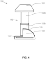
- a resection guide member 130 may then be utilised to correct for any mismatch therebetween.
- the housing 110 is not parallel or square relative to the inner support portion 120.
- the resection guide member 130 includes a planar engagement member 131 at a proximal end thereof and an adjustable guide 134 at a distal end thereof, which are connected by an extendible arm 132.
- the engagement member 131 is of suitable dimensions for insertion into the inner space 160 of the spacer device 100 so that it is stable. It will be appreciated that other means of engaging the resection guide member 130 with the spacer device 100, including the housing 110 and the inner support portion 120 thereof, such as by clips, a tongue in groove linkage, a cog or gear linkage, a friction linkage, a magnetic linkage, or any other means of positive attachment, are envisaged for the present invention.
- the resection guide member 130 it is not essential for the resection guide member 130 to include an engagement member 131 and instead, in alternative embodiments, is irreversibly engaged or connected to the spacer device 100, such as to the second end portion 122 of the inner support portion 120 or the upper wall 111 of the housing 110.
- the resection guide member 130 include the engagement member 131 so as to be reversibly engageable with the spacer device 100.
- the resection guide member 130 is then oriented such that an adjustable guide 134 at a distal end thereof is preferenced or adjacent to the particular bone (i.e., femur or tibia) that requires correction.
- the resection guide member 130 would be placed on the tibial side of the spacer device 100 so as to be directed towards or adjacent the distal femur 801.
- the guide 133 of the resection guide member 130 further includes a guide aperture 134, which can then be set or adjusted so as to overlie a level of the extension gap 400 or flexion gap (not shown) that is considered to be of optimal dimensions by the surgeon.
- the level of the guide 134 is adjustable with respect to the resection guide member 130 by way of an extendible arm 132 extending between the engagement member 131 and the guide 133.
- the extendible arm 132 includes a first arm portion 132a that telescopically engages a second arm portion 132b so as to allow for slidable movement therebetween.
- the guide 133 may be at least partially rotatable relative to the arm 132 so as facilitate angular adjustment of the guide aperture 134 as required by the surgeon.
- the guide 133 is pivotable about a point of engagement 135 with the second arm portion 132b.
- the medial side of the extension gap 400 and/or the flexion gap was narrower and/or tighter (i.e., has a greater soft tissue tension and hence more force as measured by the spacer device 100) than the lateral side, more bone would be removed or resected from the medial side than the lateral side.
- the amount of bone that is removed is such so as to produce extension and flexion gaps of substantially equal dimensions. In this regard, it may be possible to accept a small degree of mismatch between the flexion and extension gaps.
- a standard tibial or femoral resection member may then be suitably placed or slid under the guide aperture 134 of the guide 133 of the resection guide member 130 and pinned into place to the femur 800 or tibia 900 so as to facilitate recutting of the distal femoral resection surface 802, the posterior femoral resection surface or the proximal tibial resection surface 902.
- an osteotome blade or similar may be used to hold the tibial or femoral resection member in position while it is pinned in place.
- the spacer device 100 and the resection guide member 300 can then be removed so as to allow for resection of the femur 800 or tibia 900 to proceed in the standard fashion.
- This mechanism of balancing the flexion and/or extension gaps typically allows for any variation in bone resection or correction as required rather than the typical +2;+4 type resection fine-tuning that is available with particular systems known in the art.
- the extension and flexion gaps and soft tissue balance of the patient's knee joint 700 may then be reassessed by the spacer device 100 to confirm correction of any previous imbalance thereof.
- the distal femoral resection plane is preferably substantially parallel to the proximal tibial resection plane when the knee joint 700 is in extension, such that an extension gap 400 from the tibia 900 to the femur 800 is substantially rectangular after performing distal and proximal resections.
- the proximal tibial resection plane is preferably substantially parallel to the posterior femoral resection plane, such that a flexion gap from the tibia 900 to the femur 800 is substantially rectangular after performing proximal and posterior resections.
- the extension gap is preferably of substantially equal dimensions to that of the flexion gap.
- the spacer device 100 may further assist in joint line restoration in a subject in the knee joint 700 in both flexion and extension. By way of example, this may be achieved by noting the meniscal bodies and/or remnants thereof and whether they approximately correspond to a central portion of the spacer device 100 once it is in a distracted position.
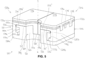
- FIG. 5 A further embodiment of a spacer device 500 is provided in Figure 5 . Similar to that for the spacer device 100 hereinbefore described, the spacer device 500 is for assisting a surgeon during knee replacement surgery, which includes a T-shaped open-sided housing 510 that defines a longitudinal axis a and an inner support portion 520.
- the inner support portion 520 has a first end portion 521 and a second end portion 522 connected by a central portion 523.
- the housing 510 is divided into approximately equally dimensioned first and second portions 510a-b that comprise a respective portion of a substantially planar upper wall 511', 511", one of a side wall 512a-b and one of first and second central axial projections 517a-b that each extend axially and distally from respective end portions of the upper walls 511', 511".
- the first and second central axial projections 517a-b are disposed within an open-sided central channel 528 at a second end 522 of the inner support portion 520 so as to be configured to allow for axial slidable movement thereof relative to each other and to the inner support portion 520.
- respective inner or medial surfaces of the first and second central axial projections 517a-b abut each other when disposed within the open-sided central channel 528, but alternative arrangements of slidably engaging or connecting the first and second central axial projections 517a-b together are envisaged.
- first and second portions 510a-b are distracted relative to the other, stability of the housing 510 is maintained, at least in part, by the respective side walls of the first and second central axial projections 517a-b abutting each other as well as the respective opposed side walls of the central channel 528.
- the first and second portions 510a-b of the housing 510 are configured to allow for independent axial and/or sagittal distraction or movement of the first portion 510a relative to the second portion 510b so as to allow for the generation of a lateral inner space (not shown) and a medial inner space (not shown).
- the upper wall 511', 511" of the housing 510 has first and second upper surfaces 511a', 511a" and first and second lower surfaces 511b', 511b".
- the upper surfaces 511a', 511a" each include a sensor channel 577a-b of suitable dimensions for receiving a respective electronic force sensor unit 570a-b disposed therein.
- each of the electronic force sensor units 570a-b include a base 575a-b having a pair of anteroposteriorly spaced apart cylindrical cup portions 576a-d, the base 575a-b being of suitable dimensions for residing within their respective sensor channel 577a-b and being engaged thereto.
- the force sensor units 570a-b further include a pair of cylindrical transfer elements 574a-d of suitable dimensions or diameter for being matingly disposed or engaged within their respective cylindrical cup portion 576a-d.
- the transfer elements 574a-d comprise a planar upper surface for the controlled transfer of forces or loads imparted thereon to their associated sensor element 590a-d.
- each of the force sensor units 570a-b further include an upper plate 571a-b for abutting a resected distal femoral surface 802 or a resected proximal tibial surface 902 so as to receive a force applied thereto by said resected distal femoral surface 802 or said resected proximal tibial surface 902 and transfer this to an underlying electronic sensor element 590a-d.
- a lower support plate 572a-b is also included in each of the force sensor units 570a-b, which is disposed between the upper plate 571a-b and their respective base 575a-b.
- Each of the lower support plates 572a-b include a pair of anteroposteriorly spaced elongate slots 573a-d, which are positioned parallel to each other so as to overly and receive therein the planar upper surface of their respective transfer elements 574a-d.
- the sensor elements 590a-d comprise thin film sensors disposed within each of the elongate slots 573a-d in the lower support plates 572a-b.
- one or both of the support plates 572a-b comprises a thin metal plate having one or a plurality of strain gauges disposed thereon.
- the upper plates 571a-b and the support plates 572a-b each include laterally and medially positioned and downwardly projecting mating elements or projections 578a-f, 579a-f that are adapted to be matingly received within corresponding mating channels 580a-f, 581a-f provided in upper portions of both medial and lateral surfaces of the side wall 512a-b.
- These mating channels 580a-f, 581a-f and their corresponding mating projections 578a-f, 579a-f function to stabilize and align the aforementioned components of the force sensor units 570a-b during use.
- the housing 510 comprises a pair of directly opposed side walls 512a-b.
- Each of the side walls 512a-b extends axially and distally from a respective end portion of the lower surfaces 511 b', 511b" of the upper wall 511', 511" so as to form a pair of channels 514a-b in which to receive the inner support portion 520.
- the side walls 512a-b further include a respective inwardly projecting tab 513a-b at a distal end thereof that assist in maintaining the inner support portion 520 disposed within the housing 510.
- the second end portion 522 and the central portion 523 are, at least partially, disposed between the side walls 512a-b of the housing 510 and are maintained in this position by virtue of the second end portion 522 having a second pair of radially extending tabs 525a-b, which may contact their respective and opposing inwardly projecting tab 513a-b of the housing 510 upon distraction of the spacer device 500 (i.e., axial movement of the inner support portion 520 relative to the housing 510).
- the first end portion 521 of the inner support portion 520 also includes a first pair of radially extending tabs 524a-b.
- the first pair of radially extending tabs 524a-b are longer in dimension than the second pair of radially extending tabs 525a-b. To this end, the first pair of radially extending tabs 524a-b are configured to be positioned adjacent or abut the resected proximal tibial surface 902 when in use.
- first and second portions 510a-b of the housing 510 of the spacer device 500 can now be extended or distracted along its longitudinal axis a relative to the inner support portion 520. Similar to that described for the previous embodiment, axial movement of the first and second portions 510a-b relative to the inner support portion 520 results in the generation of the lateral and medial inner spaces (not shown) that are defined by the respective lower surfaces 511b', 511b" of the upper wall 511', 511", the side walls 512a-b and the central axial projections 517a-b of the housing 510 and the second end portion 522 of the inner support portion 520.
- first space (not shown) and a second space (not shown), each located between or defined by their respective inwardly projecting tab 513a-b of the side walls 512a-b and the opposing first pair of radially extending tabs 524a-b.
- first and second spaces (not shown) and/or the lateral and medial inner spaces (not shown) may then be utilised for receiving a suitably dimensioned spacer element (not shown) so as to maintain the spacer device 500 in the desired distracted position and allow for measurement of soft tissue tension by one or both of the electronic force sensor units 570a-b as well as assessment of dimensions of the extension and/or flexion gap as previously described for the spacer device 100.
- the spacer device 500 further includes a centrally and posteriorly positioned hemi-cylindrical channel 595, which extends longitudinally from the top plate 571a-b through the support plate 572a-b, the housing 510 and the inner support portion 520 so as to define a space therethrough adapted to receive the anterior and/or posterior cruciate ligaments therein.
- one or more further electronic force sensor units could be disposed on or in one or more additional surfaces of the spacer device 500.
- a further electronic force sensor unit may be disposed within the hemi-cylindrical channel 595 or a posterior surface of, for example, the inner support portion 520, so as to assess soft tissue tension in respect of the posterior cruciate ligament.
- one or more further electronic force sensor units could be disposed in or on one or more of the lateral surfaces of the spacer device 500, such as the side walls 512a-b, in order to facilitate assessment of soft tissue tension in relation to the collateral ligaments adjacent thereto.
- FIG. 7 An alternative embodiment of a spacer device 1000 is provided in Figure 7 . Similar to that for the spacer device 100, 500 previously described, the spacer device 1000 is for assisting a surgeon during knee replacement surgery, which includes a T-shaped open-sided housing 1010 that defines a longitudinal axis a and an inner support portion 1020.
- the inner support portion 1020 has a first end portion 1021 and a second end portion 1022 connected by a central portion 1023.
- the housing 1010 includes a central axial projection 1017a-b that extends axially and distally from a substantially planar upper wall 1011a-b thereof and is disposed within an open-sided central channel 1028 at a second end 1022 of the inner support portion 1020 so as to be configured to allow for axial slidable movement thereof relative to the inner support portion 1020.
- the housing 1010 is composed of approximately equally dimensioned first and second portions 1010a-b reversibly engaged together at a central portion of first and second portions of an upper wall 1011', 1011" and the central axial projection 1017a-b by a mortise and tenon joint comprising a channel 1019a in the first portion 1010a and an opposing projection 1019b in the second portion 1010b, the channel 1019a of suitable dimensions for receiving said projection 1019a therein. It will be understood that other means of reversibly engaging the first and second portions 1010a-b, as are known in the art, are contemplated for the present embodiment.
- each of the first and second portions 1010a-b includes a respective portion of the upper wall 1011', 1011", one of the side walls 1012a-b and a portion of the central axial projection 1017a-b.
- the first and second portions 1010a-b of the housing 1010 are configured to allow for independent axial and/or sagittal distraction or movement of the first portion 1010a relative to the second portion 1010b so as to allow for the generation of a lateral inner space 1060a and a medial inner space 1060b.
- a force sensor (not shown) may be placed in each of the lateral and medial inner spaces 1060a-b to assess soft tissue tension across the knee joint.
- one or more spacer elements could be inserted into the lateral and medial inner spaces 1060a-b so as to maintain the spacer device 1000 in the distracted position.
- the upper wall 1011', 1011" of the housing 1010 has first and second upper surfaces 1011a', 101 1a" and first and second lower surfaces 1011b', 1011b".
- the upper surfaces 1011a', 101 1a" are of suitable dimensions to abut or receive a resected distal femoral surface 802 so as to receive a force applied thereto by said resected distal femoral surface 802.
- the housing 1010 further comprises a pair of directly opposed side walls 1012a-b.
- Each of the side walls 1012a-b extends axially and distally from a respective end portion of the lower surfaces 1011b', 1011b" of the upper wall 1011', 1011" so as to form a pair of channels 1014a-b in which to receive the inner support portion 1020.
- the side walls 1012a-b further include a respective inwardly projecting tab 1013a-b at a distal end thereof that assist in maintaining the inner support portion 1020 disposed within the housing 1010.
- the second end portion 1022 and the central portion 1023 are, at least partially, disposed between the side walls 1012a-b of the housing 1010 and are maintained in this position by virtue of the second end portion 1022 having a second pair of radially extending tabs 1025a-b, which may contact their respective and opposing inwardly projecting tab 1013a-b of the housing 1010 upon distraction of the spacer device 1000 (i.e., axial movement of the inner support portion 1020 relative to the housing 1010).
- the first end portion 1021 of the inner support portion 1020 also includes a first pair of radially extending tabs 1024a-b.
- the first pair of radially extending tabs 1024a-b are longer in dimension than the second pair of radially extending tabs 1025a-b. To this end, the first pair of radially extending tabs 1024a-b are configured to be positioned adjacent or abut the resected proximal tibial surface 902 when in use.
- the first end 1021 of the inner support portion 1020 further includes a distal channel 1029.
- the height of the spacer device 1000 can be adjusted, such as by reversibly attaching or engaging a foot portion (not shown) to the distal channel 1029.
- the overall height of the spacer device 1000 can be approximated to accommodate the extension gap 400 and/or flexion gap regardless of their dimensions and then this height can be fine tuned with spacer elements (not shown) as required.
- first and second portions 1010a-b of the housing 1010 of the spacer device 1000 can now be extended or distracted along its longitudinal axis a relative to the inner support portion 1020. Similar to that described for the previous embodiment, axial movement of the first and second portions 1010a-b relative to the inner support portion 1020 results in the generation of the lateral and medial inner spaces 1060a-b for receiving a force sensor (not shown) therein.
- the force sensor can be an electronic force sensor disposed in or on: (a) an upper and/or lower surface of the one or both of the first pair of radially extending tabs 1024a-b of the inner support portion 1020; (b) a lower surface of one or both of the inwardly projecting tabs 1013a-b of the side walls 1012a-b of the housing 1010; (c) the upper surface 1011a of the upper wall 1011of the housing 1010; (d) an outer or lateral surface of one or both of the side walls 1012a-b, (e) an outer or lower surface of the first end 1021 of the inner support portion 1020; and/or (f) one or more of the spacer elements (not shown).
- first space I040 and a second space I050 each located between or defined by their respective inwardly projecting tab 1013a-b of the side walls 1012a-b and the opposing first pair of radially extending tabs 1024a-b.
- first and second spaces 1040, 1050 may then be utilised for receiving a suitably dimensioned spacer element (not shown) so as to maintain the spacer device 1000 in the desired distracted position and allow for measurement of soft tissue tension as well as assessment of dimensions of the extension and/or flexion gap as previously described for the spacer device 100, 500.
- the spacer devices 100, 500 and 1000 hereinbefore described may be constructed from a variety of materials, including a surgical grade material, such as surgical grade plastic or metal (e.g., surgical grade stainless steel, titanium, or cobalt- chrome), that is capable of withstanding the forces applied by the femur and tibia thereon, while also preferably being biocompatible and resistant to corrosion.
- a surgical grade material such as surgical grade plastic or metal (e.g., surgical grade stainless steel, titanium, or cobalt- chrome)
- surgical grade plastic or metal e.g., surgical grade stainless steel, titanium, or cobalt- chrome
Description
- THIS INVENTION relates to a device for use in knee surgery. In particular, the invention is directed to a spacer device for use in knee surgery on a subject and, in particular, total knee replacement that facilitates optimal soft tissue balancing via measurement of bone displacement and one or more forces exerted thereon.
- Total knee replacement surgery is an increasingly common and expensive procedure. A successful outcome largely rests on the ability to match the flexion and extension gaps of the knee joint. True balance is reflected both by appropriate force being applied to the medial and lateral aspects of the knee joint as well as the excursion of the soft tissues on either side of the knee joint. These concepts are important if excessive excursion of the soft tissues is possible after knee replacement surgery. To this end, forces that may have been evenly distributed in a non-dynamic setting, may then cause uneven forces to be applied to the knee replacement prosthesis during the dynamic portion of movement. Similarly, if there is excessive lack of excursion (i.e., tightness) of the soft tissues then during dynamic movement the forces may be concentrated on one side of the joint. Alternatively, the forces within the knee joint may be equal or minimally different, but be too low or high.
- Means of achieving a balanced knee in total knee replacement surgery currently exist, such as with the use of robotic surgical systems, computer assisted surgery or force registering sensors. Typically, these systems are complex and expensive. Furthermore, such systems generally achieve one but not both of: (a) measuring the total width of the flexion and extension gaps on both the medial and lateral sides of the knee; and (b) measuring the force that is present on the medial and lateral sides of the knee joint when the soft tissues are placed under tension. Accordingly, there remains a need for a simple, cheap and reproducible means for achieving both of these goals in total knee replacement surgery. As noted above, this is important for achieving an optimal patient outcome after a total knee replacement, as well as important generally to the healthcare system by providing a relatively cheap and cost efficient means of conducting surgery. As the cost of provision of healthcare rises more complex and expensive systems may not provide the necessary surgical outcomes in a cost-efficient manner.
- The invention is defined by the appended claim 1. Optional features are set forth in the dependent claims.
- It will be appreciated that the indefinite articles "a" and "an" are not to be read as singular indefinite articles or as otherwise excluding more than one or more than a single subject to which the indefinite article refers.
- As used herein, unless the context requires otherwise, the words "comprise", "comprises" and "comprising" will be understood to mean the inclusion of a stated integer or group of integers but not the exclusion of any other non-stated integer or group of integers.
- In order that the present invention may be readily understood and put into practical effect, reference will now be made to the accompanying illustrations, wherein like reference numerals are used to refer to like elements.
-
Figure 1 : is a perspective view of an embodiment of a spacer device in a collapsed position; -
Figure 2 : is a further perspective view of the spacer device ofFigure 1 in a distracted position; -
Figure 3 : is a perspective view of the spacer device ofFigure 1 together with a force sensor inserted within an extended knee; -
Figure 4 : is a perspective view of a resection guide member for use with the spacer device ofFigure 1 ; -
Figure 5 : is a perspective view of another embodiment of a spacer device in a collapsed position; -
Figure 6 : is an exploded view of the spacer device ofFigure 5 ; and -
Figure 7 : is a perspective view of a further embodiment of a spacer device. - The present invention relates to a spacer device for use during surgery and, in particular, TKR/TKA, for determining appropriate soft tissue balance of the knee joint in extension and/orflexion. While the spacer device described herein is particularly suited for use in TKR/TKA, the present invention has general applicability to all types of joints (e.g., elbows, shoulders, wrists and fingers) and replacement surgery thereof that requires accurate gap balancing, joint alignment and/or soft tissue balancing.
-
US 2006/111790 describes an adjustable tibial trial insert that includes an upper plate having an upper articular surface and a lower plate together with a height-adjustment mechanism coupled to and positioned generally between the upper plate and the lower plate. -
US 2014/094715 provides a distractor system for measuring a force, pressure, or load applied by the muscular-skeletal system that includes a first support structure, a second support structure, a lift mechanism coupled to the first structure and the second support structure where the lift mechanism is configured to adjustable separate the first and second support structures, a sensor array overlying the second support structure where the sensor array comprises a plurality of capacitors, and a third support structure coupled to the sensor array -
US 2016/199077 discloses devices that are used to establish a distal femoral or proximal tibial resection position and a prosthetic gap in a total knee arthroplasty procedure that include a support that attaches to and references a proximal resected tibia or distal resected femur and supports and establishes the position of a resection guide. -
US 2005/020941 describes a dynamic spacer for measuring a flexion-extension gap during total knee arthroplasty, which includes a first planar member having a lower tissue engaging surface, a second planar member having an upper tissue engaging surface and a tensioner disposed therebetween. -
US 2007/239165 provides a spacer block for gathering data to be used in the selection of a trial insert that includes a first body piece, a second body piece positioned on top of the first body piece, and at least one chim positioned on top of the second body piece. -
US 2013/066432 discloses an apparatus that includes a first portion configured to be coupled to a first bony structure, a second portion configured to be coupled between the first portion and a second bony structure, and a transducer and an actuator coupled between the first portion and the second portion. -
WO 99/35972 - Appropriate soft tissue balancing requires placing the soft tissues surrounding and/or interconnecting the bones of the knee at an approximately equal or similar tension relative to one another when the femur and its corresponding tibia are placed in a desired alignment as determined by the surgeon. Preferably, this tension is approximately equal or similar to the physiological tension of these soft tissues in the native knee at rest. Non-limiting examples of the soft tissues surrounding and/or interconnecting the bones of the knee include the medial and lateral collateral ligaments, the anterior and posterior cruciate ligaments, the posteromedial and posterolateral ligamentous structures and the posterior capsule.
- While the principles described herein are based on methods of providing surgical devices for humans, this invention may also be extended to other mammals such as livestock (e.g. cattle, sheep), performance animals (e.g. racehorses) and domestic pets (e.g. dogs, cats), although without limitation thereto.
- A
spacer device 100 according to particular embodiments is adapted to be used during TKA for precise realignment and soft tissue tensioning of theknee joint 700 inflexion and/or extension by providing appropriate medial and/or lateral spacing between the respective resectedsurfaces distal femur 801 and theproximal tibia 901. Thus, thespacer device 100 is designed to result in appropriate forces being applied across theknee joint 700 after placement of an appropriately sized knee replacement prosthesis therein. Furthermore, in particular embodiments, thespacer device 100 is adapted to ensure that there is adequate space for the particular patient's replacement implant, as well as that the resection planes of theproximal tibia 901 anddistal femur 801 are substantially parallel in the coronal and sagittal planes. - As noted above, various embodiments of the present invention provide spacer devices for assisting a surgeon during TKA. Referring to the figures and, in particular,
FIG. 1 , there is shown aspacer device 100 for assisting a surgeon during TKA, where the system generally includes a open-sided housing 110 that defines a longitudinal axis a and an I-shapedinner support portion 120 disposed therein such that theinner support portion 120 is configured to allow for axial slidable movement thereof relative to thehousing 110. - In the embodiment provided, the
housing 110 includes a substantially planarupper wall 111 having anupper surface 111a and alower surface 111b. As can be observed inFigure 1 , theupper surface 111a is of suitable dimensions to abut or receive a resected distalfemoral surface 802 so as to receive a force applied thereto by said resected distalfemoral surface 802. Thehousing 110 further comprises a pair of directly opposedside walls 112a-b. Each of theseside walls 112a-b extends axially and distally from a respective end portion of thelower surface 111b of theupper wall 111 so as to form a pair ofchannels 114a-b in which to receive theinner support portion 120. Theside walls 112a-b each further include a respective inwardly projectingtab 113a-b at a distal end thereof that assist in maintaining theinner support portion 120 disposed within thehousing 110. - As shown in
Figures 1 to 3 , thehousing 110 is composed of approximately equally dimensioned first andsecond portions 110a-b reversibly engaged together at a central portion of theupper wall 111 by a mortise and tenon joint comprising achannel 119a in thefirst portion 110a and anopposing projection 119b in thesecond portion 110b, thechannel 119a of suitable dimensions for receiving saidprojection 119a therein. Other means of reversibly engaging the first andsecond portions 110a-b are contemplated, such as a ball and socket joint and other means as are known in the art. In this manner, each of the first andsecond portions 110a-b includes a portion of theupper wall 111 and one of theside walls 112a-b. By virtue of this arrangement, the first andsecond portions 110a-b of thehousing 110 are configured to not only allow for independent axial and/or radial distraction of thefirst portion 110a relative to thesecond portion 110b but also movement of the first andsecond portions 110a-b of thehousing 110 in coronal and/or sagittal planes of theknee joint 700. As each of the first andsecond portions 110a-b are distracted, stability of thehousing 110 is maintained, at least in part, by the respective side walls of theprojection 119b and thechannel 119a abutting each other. An additional support element (not shown) may also be slotted or placed into aninner space 160 to maintain stable distraction of the first andsecond portions 110a-b if required. - It will be appreciated by the skilled artisan, however, that the
spacer device 100 may be utilised without such movement or distraction of thefirst portion 110a relative to thesecond portion 110b. Accordingly, in alternative embodiments, thehousing 110 of thespacer device 100 is of a single, unitary structure. - The
inner support portion 120 has afirst end portion 121 and asecond end portion 122 connected by acentral portion 123. Thesecond end portion 122 and thecentral portion 123 are, at least partially, disposed between theside walls 112a-b of thehousing 110 and are maintained in this position by virtue of thesecond end portion 122 having a second pair of radially extendingtabs 125a-b, which may contact their respective and opposing inwardly projectingtab 113a-b of thehousing 110 upon distraction of the spacer device 100 (i.e., axial movement of theinner support portion 120 relative to the housing 110). Thefirst end portion 121 of theinner support portion 120 also includes a first pair of radially extendingtabs 124a-b. As can be observed fromFigure 1 , the first pair of radially extendingtabs 124a-b are longer in dimension than the second pair of radially extendingtabs 125a-b. To this end, the first pair of radially extendingtabs 124a-b are configured to be positioned adjacent or abut the resected proximaltibial surface 902 when in use. - It will be appreciated that the
spacer device 100 will preferably also function in the opposite orientation than that presented inFigures 1 through 3 , such that theupper surface 111a of thehousing 110 is alternatively positioned adjacent the resected proximaltibial surface 902 and thefirst end portion 121 of theinner support portion 120 is positioned adjacent the resected distalfemoral surface 802. - Suitably, the
spacer device 100 described herein is for use when the knee joint 700 is in full extension (i.e., approximately 180 degrees). The skilled artisan, however, would appreciate that this may not be possible or feasible in all patients, owing, for example, to the presence of pre-existing disease or deformities of the limb. By way of example, a patient with a flexion deformity or contracture of the knee may be physically unable to fully straighten or extend the knee. Accordingly, in certain embodiments, thespacer device 100 provided herein is used when the knee joint 700 is not fully extended. - As used herein, the terms "approximately" and "about" refer to tolerances or variances associated with numerical values recited herein. The extent of such tolerances and variances are well understood by persons skilled in the art. Typically, such tolerances and variances do not compromise the structure, function and/or implementation of the devices and methods described herein.
- Suitably, prior to insertion of the
spacer device 100, the knee joint 700 is exposed and thedistal femur 801 and theproximal tibia 901 are resected to thereby establish anappropriate extension gap 400 of the knee joint 700, as shown inFigure 3 . Preferably, resection of theproximal tibia 901 and/or thedistal femur 801 requires the determination of a joint line on, for example, a three dimensional model of the aligned knee in extension and/or flexion. As would be readily understood, engagement of the lateral and medial femoral condyles with the superior surface of the tibia of the extended knee establishes a joint line. Accordingly, such determination may be made at least in part from one or more anatomical indicators, including, but not limited to, a distal portion of a medial condyle, a distal portion of a lateral condyle, a proximal portion of the medial tibial plateau, a proximal portion of the lateral tibial plateau, a central portion of a lateral meniscus and a central portion of a medial meniscus. - The collapsed two-
part spacer device 100 is then inserted into theextension gap 400, as illustrated inFigure 3 . It will be appreciated that theextension gap 400 in most primary knee replacements will be about 17 mm to about 22 mm, and more particularly about 19 mm to about 20 mm, although this may vary between different knee surgical systems as are known in the art. As such, the exact dimensions of thecollapsed spacer device 100 so as to reside within the extended and/or flexed knee may depend on the particular knee surgical system used. Moreover, the dimensions of thespacer device 100 would also likely vary for use in revision knee replacement surgery. Nonetheless, for ease of insertion, thespacer device 100 is generally smaller in height than theextension gap 400 and/or the flexion gap (not shown). Accordingly, in particular embodiments of the present invention, thespacer device 100 is about 10 mm to about 16 mm (e.g., about, 10, 10.5, 11, 11.5, 12, 12.5, 13, 13.5, 14, 14.5, 15, 15.5, 16 mm and any range therein) in height when in a collapsed position so as to allow for insertion into theextension gap 400 between the resected distalfemoral surface 802 and the resected proximal tibial surface. It will be apparent to the skilled artisan that aspacer device 100 of similar height dimensions (e.g., about 10 mm to about 16 mm in the collapsed position) would also be suitable for insertion into the flexion gap (not shown) of the knee joint 700 in flexion. - In a particular embodiment, the height of the
spacer device 100 can be adjusted, such as by reversibly attaching or engaging a foot portion (not shown), such as via a mortise and tenon joint or other engagement member as are known in the art, with thefirst end 121 of theinner support portion 120. By virtue of this arrangement, the height of thespacer device 100 can be approximated to accommodate theextension gap 400 and/or flexion gap regardless of their dimensions and then this height can be fine tuned with thespacer elements - In certain embodiments, the
spacer device 100 has a width dimension of about 50 mm to about 80 mm and a thickness or depth dimension of about 50 mm to about 80 mm. Therefore, thespacer device 100 may be at least as large as the leading edges of the resected femoral andtibial surfaces spacer device 100 may be about 20 mm to about 50 mm in depth and width in order to substantially conform to the resected leading edges of the resected femoral andtibial surfaces spacer device 100 described herein will depend to some degree on the size of the knee joint 700 to which thedevice 100 is to be applied. - It is further envisaged that particular embodiments of the
spacer device 100 may be configured or of dimensions for use in unicompartmental knee replacement (i.e., on the lateral ormedial side spacer device 100 may be adapted for use in bicruciate retaining total knee replacement surgery. In such an embodiment, thespacer device 100 would need a posterior channel adapted to receive the cruciate ligament that have been left in-situ therein and the medial and lateral sides of thespacer device 100 would be connected by an anterior bridge. Alternatively, twoseparate spacer devices 100 may be utilised in the medial andlateral sides knee joint 700. - During use, the
spacer device 100 is typically positioned between thedistal femur 801 and theproximal tibia 901 when the leg is fully extended (seeFigure 3 ) or in about 90 degrees of flexion (not shown). As such, when in this configuration, thespacer device 100 is typically adjacent to, and in direct contact with (i.e., abutting), a resected surface of each of thefemur 800 and thetibia 900 of the patient. To this end, when positioned in the extended knee, thespacer device 100 typically abuts both of the resected proximaltibial surface 902 and the resected distalfemoral surface 802. Whilst, when in the flexed knee, thespacer device 100 generally abuts both of the resected proximaltibial surface 902 and a posterior femoral surface (not shown), which may or may not be already resected. In this regard, thespacer block 100 is positioned adjacent to the resectedfemur 800 andtibia 900 for determining appropriate spacing therebetween and subsequently a contact force and/or pressure exerted on thespacer device 100 when in a distracted position. Thespacer block 100 is preferably adapted to be easily removed (e.g., via a sliding movement) from between the resectedfemur 800 andtibia 900 in order to make subsequent resections or adjustments to the replacement implant. - Once appropriately positioned within the knee joint 700, the
spacer device 100 can now be extended or distracted along its longitudinal axis a. By way of example, thespacer device 100 can be distracted or extended by the action of one or more laminar spreaders inserted between theupper wall 111 of thehousing 110 and thesecond end portion 122 of theinner support portion 120. Ananterior face 125 of theinner support portion 120 may include gradations, such as millimetre gradations or degrees of rotation gradations, so as to indicate to the surgeon the distance of distraction of thehousing 110 relative to theinner support portion 120 both laterally and medially thereto. In this regard, it will be appreciated that an anterior surface of one or both of theside walls - As can be observed in
Figures 2 and3 , distraction or extension of thespacer device 100 by axial movement of theinner support portion 120 relative to thehousing 110 results in the formation of afirst space 140 and asecond space 150, each located between or defined by their respective inwardly projectingtab 113a-b of theside walls 112a-b and the opposing first pair of radially extendingtabs 124a-b. In referring toFigures 2 and3 , an appropriately dimensionedfirst spacer element 201 is inserted into thefirst space 140 and an appropriately dimensionedsecond spacer element 202 is inserted into thesecond space 150 so as to maintain thespacer device 100 in the distracted position. In the embodiment provided, thespacer elements spacer device 100 could be achieved byalternative spacer elements - In addition or alternatively to the above, it will be appreciated that one or both of the
spacer elements inner space 160 so as to maintain thespacer device 100 in the distracted position. Such an arrangement may be used in embodiments in which a force sensor, and more particularly, an electronic force sensor, is disposed on or in or is integral with, for example, theupper surface 111a of the upper wall 111of thehousing 110, an outer or lateral surface of one or both of theside walls 112a-b and/or an outer or lower surface of thefirst end 121 of theinner support portion 120. - In one particular embodiment not shown herein, the
spacer elements radially extending tabs 124a-b of theinner support portion 120 and/or the inwardly projectingtabs 113a-b of thehousing 110. The opposite arrangement is also envisaged in which the spacedelements radially extending tabs 124a-b and/or the inwardly projectingtabs 113a-b comprise the corresponding rounded portions for engagement therewith. Such an arrangement facilitates at least partial rotation of theinner support portion 120 relative to thehousing 110 if required. - Preferably, the
spacer elements first space 140 and/or thesecond space 150, as defined by the respective inwardly projectingtabs 113a-b of theside walls 112a-b and the first pair of radially extendingtabs 124a-b, may include a range of dimensions so as to provide a surgeon with choice ofspacer elements 201 in their attempts to at least partly facilitate return of the knee joint to an appropriate alignment and/or an appropriate soft tissue balance. By way of example, thespacer element spacer device 100 may come in a range of sizes, such as about 4 mm to about 20 mm and typically increase in one millimetre increments (e.g., about 4, 5, 6, 7, 8, 9, 10, 11, 12, 13, 14, 15, 16, 17, 18, 19, 20 mm and any range therein). The surgeon will generally continue inserting increasing sizes of thespacer elements second spaces extension gap 400 and flexion gap (not shown) have reached an optimal and preferably substantially matching or equivalent tension. In this regard, a different sizedfirst spacer element 201 may be required for balancing thelateral side 701 of the knee joint 700 versus thesecond spacer element 202 used for themedial side 702 thereof. This may depend upon the individual's preoperative knee anatomy, which may be determined by, for example, magnetic resonance imaging (MRI) or computed tomography (CT), and the presence of any anatomical deformities and/or defects, such as varus or valgus. - By way of example, in
Figure 2 , the first spacer element is 6 mm in height, whereas the second spacer element is 4 mm in height so as to balance theknee joint 700. Such discrepancies in the height or dimensions of the first andsecond spacer elements proximal tibia 901 and/ordistal femur 801 are required so as to achieve resection planes of thefemur 800 andtibia 900 that are substantially parallel in the extended and/or flexedknee joint 700. - Additionally, the
spacer device 100 facilitates measurement of not only maximal displacement of the knee joint 700 and one or more forces at this point, but also the forces present at submaximal displacement of theknee joint 700. By way of example, maximal displacement of the knee joint 700 may indicate via thespacer elements medial side 702 will accommodate an 11 mm polyethylene component of the knee joint prosthesis, whilst thelateral side 701 will conversely accommodate a 13 mm polyethylene component. Thespacer elements second spaces proximal tibia 901 and/ordistal femur 801 require adjustment so as to achieve substantially parallel resection planes thereof in the coronal and sagittal planes as well as substantially equivalent soft tissue balancing or tensioning across theknee joint 700. - Accordingly, following placement of the
spacer elements extension gap 400 across both the medial andlateral aspects knee joint 700. Accordingly, this allows for both a minimumappropriate extension gap 400 to be provided and the determination of any discrepancy in theextension gap 400 between the medial andlateral aspects knee joint 700. This may also allow for the surgeon to further assess any tilting of theupper surface 111a of theupper wall 111 and/or thefirst end 121 of theinner support portion 120 relative to the resected distalfemoral surface 802 or resected proximaltibial surface 902 they are contacting or abutting in situ as well as any tilting of thehousing 110 and/or theinner support portion 120 in relation to thespacer elements tibial surface 902 has been achieved. - As shown in
Figures 2 and3 , once thespacer device 100 has been extended or distracted, theinner space 160 also results or is produced between thelower surface 111b of theupper wall 111 of thehousing 110 and thesecond end portion 122 of theinner support portion 120. Theinner space 160 is for receiving aforce sensor 300 therein. It is contemplated that theforce sensor 300 may take a number of forms as are known in the art. By way of example, theforce sensor 300 may include pressure sensitive foam, which may or may not be resiliently deformable (i.e., have "memory"). In such embodiments, the pressure sensitive foam is preferably sensitive to various forces or pressures so as to facilitate multiple assessments for the lateral andmedial sides knee joint 700. Additionally, the pressure sensitive foam may include or incorporate a dye, which is released when the foam is deformed thus indicating the degree of pressure placed on eitherside knee joint 700. - In other embodiments, the
force sensor 300 may include a block member with one or more force sensing elements or pads thereon together with a force readout device or display, such as a pressure gauge or a force gauge. The force sensing elements can be, for example, any suitable sensing element capable of detecting and acquiring data indicative of forces applied by each of the resectedfemur 800 andtibia 900 on thespacer device 100. Suitable force sensing elements include, for example, a piezoelectric sensor, a strain gauge, a transducer, a load cell, or the like, as are known in the art. In one particular embodiment, the one or more force sensing elements may include one or more inflatable elements in fluid communication with a syringe or the like so as to be inflated with air or saline upon insertion into theinner space 160. It will be apparent thatsuch force sensors 300 may capable or designed for multiple uses. Theforce sensor 300 can include an array of force sensing elements which may, for example, be arranged in a grid or other suitable geometrical arrangement. Preferably, theforce sensor 300 is arranged or configured to measure a first force on alateral side 701 of the knee joint 700 and a second force on amedial side 702 of theknee joint 700. - Once the
force sensor 300 has been inserted into theinner space 160, preferably in a manner so as to assess soft tissue tension in both the medial andlateral sides spacer elements force sensor 300 can be assessed. Alternatively, and with particular respect to theaforementioned force sensor 300 comprising inflatable elements, sufficient pressure or force may be generated within theinner space 160 by theforce sensor 300, such as by inflation of the inflatable elements, to the threshold that just allows for removal of thespacer elements second spaces lateral sides knee joint 700. Regardless of the method chosen, thespacer device 100 allows for a thorough assessment of theextension gap 400 in terms of both its actual dimensions as well as the soft tissue tension on either side thereof (i.e., both medial andlateral sides spacer device 100 that the surgeon has determined to be optimal in this regard. - After assessing the
extension gap 400, as hereinbefore described and illustrated inFigure 3 , the flexion gap (not shown) may also be assessed using thespacer device 100. Preferably, with respect to use of thespacer device 100 described herein in the limb in flexion, the knee joint 700 is in approximately 85 to approximately 95 degrees of flexion (e.g., 85, 86, 87, 88, 89, 90, 91, 92, 93, 94, 95 degrees, and any range therein). In a particular preferred embodiment, the knee joint 700 is in approximately 90 degrees of flexion. There are, however, knee replacement systems, such as the Journey TKR systems by Smith and Nephew, that require the flexion angle of the knee joint 700 to be approximately 100 to 110 degrees (e.g., 100, 101, 102, 103, 104, 105, 106, 107, 108, 109, 110 degrees and any range therein). Nonetheless, it should be readily apparent to the skilled artisan that thespacer device 100 described herein is not to be limited to use with any particular knee replacement surgical system or method. Accordingly, in certain embodiments, for use of thespacer device 100 in the flexed knee, the knee joint 700 is in approximately 95 to approximately 110 degrees of flexion, including, but not limited to, 95, 95.5, 96, 96.5, 97, 97.5, 98, 98.5, 99, 99.5, 100, 100.5, 101, 101.5, 102, 102.5, 103, 103.5, 104, 104.5, 105, 105.5, 106, 106.5, 107, 107.5, 108, 108.5, 109, 109.5, 110 degrees or any range therein. In a particular preferred embodiment, the knee joint 700 is in approximately 105 degrees of flexion. - In an alternative embodiment to that described above, the
force sensor 300 is, for example, an electronic force sensor disposed in or on or connected to: (a) an upper and/or lower surface of the one or both of the first pair of radially extendingtabs 124a-b of theinner support portion 120; (b) a lower surface of one or both of the inwardly projectingtabs 113a-b of theside walls 112a-b of thehousing 110; (c) theupper surface 111a of the upper wall 111of thehousing 110; (d) an outer or lateral surface of one or both of theside walls 112a-b, (e) an outer or lower surface of thefirst end 121 of theinner support portion 120; and/or (f) one or more of thespacer elements force sensor 300 into theinner space 160. Instead, force measurements can be made directly after insertion of thespacer elements second spaces force sensor 300 could be disposed on or in any surface of thespacer device 100, including lateral and medial surfaces thereof. By virtue of this arrangement, theforce sensor 300 can be capable of measuring not only those axial or longitudinal forces exerted on, for example, upper and/or lower surfaces of thehousing 110 and theinner support portion 120 during distraction of thespacer device 100, but also pressure from the soft tissue positioned immediately around or adjacent thespacer device 100, such as the collateral ligaments and cruciate ligaments. - With respect to the above, force data measured or acquired by the
force sensor 300 may be transmitted by any wired means and/or wirelessly to an external or remotely located computer device or display screen. In typical embodiments, the force data can be transmitted by way of a conventional data transmission protocol as are known in the art, such as BlueTooth or the like. In an alternative embodiment, the force data measured or acquired by theforce sensor 300 is transmitted wired and/or wirelessly to display screen disposed in or on thespacer device 100 itself. - Prior to insertion of the
spacer device 100 into the flexed knee joint, bony resections, such as of the posterior femoral condyles, may be undertaken as per standard surgical techniques known in the art. Thespacer device 100 is then inserted into the flexed knee joint, so as to be positioned adjacent the resected proximaltibial surface 902 and a resected posterior femoral surface (not shown). Distraction of thespacer device 100 is then performed as per the method described for the extended knee joint 700 above, so as to allow for assessment of the flexion gap in terms of both dimensions and soft tissue tension on the medial and lateral aspects thereof. Surgery can then continue with adjustments occurring as necessary for any discrepancy of significance that is noted in terms of a mismatch between: (a) the respective dimensions of the extension and flexion gaps; (b) soft tissue tension between the medial and lateral sides of the joint in either flexion or extension. - In an alternative embodiment for assessing the flexion gap, the
spacer device 100 is inserted into the flexed knee joint prior to resection of the posterior femoral condyles. Accordingly, thespacer device 100 is preferably of a thickness or depth dimension (e.g., about 8 mm to about 10 mm) so as to extend under the posterior condyles of thefemur 800. Alternatively, thespacer device 100 may include paddle-like projections that extend under the posterior condyles.Longer spacer elements tibia 900 and the posterior condyles of thefemur 800 so as to facilitate distraction of thefemur 800 relative to thetibia 900. Additionally, a smaller anterior portion (not shown) contacting the anterior face of thefemur 800 may further be distracted by the appropriate residual amount to match theextension gap 400. - This would allow for distraction of the knee joint 700 by the
spacer device 100 and assessment of soft tissue tension prior to resection of the posterior femoral condyles. To this end, the degree of distraction of thespacer device 100 in the flexed knee would be preferably matched or equivalent to that previously determined for thecorresponding extension gap 400. When such a distracted position has been attained by thespacer device 100, the proposed posterior femoral resection plane may be marked and theforce sensor 300 is again inserted into theinner space 160 between thehousing 110 and theinner support portion 120 to assess whether the proposed resection would produce optimal flexion forces both medially and laterally as well as substantially match those already measured for theextension gap 400. - In the event that the
spacer device 100 indicates that the flexion gap and/or theextension gap 400 are not substantially balanced (i.e., when one aspect or side of the extension or flexion gap is narrower than the other and/or when one of the extension or flexion gap is of smaller dimensions than its corresponding flexion or extension gap), aresection guide member 130 may then be utilised to correct for any mismatch therebetween. In this regard, whenspacer elements second spaces housing 110 is not parallel or square relative to theinner support portion 120. - In the embodiment provided in
Figure 4 , theresection guide member 130 includes aplanar engagement member 131 at a proximal end thereof and anadjustable guide 134 at a distal end thereof, which are connected by anextendible arm 132. Theengagement member 131 is of suitable dimensions for insertion into theinner space 160 of thespacer device 100 so that it is stable. It will be appreciated that other means of engaging theresection guide member 130 with thespacer device 100, including thehousing 110 and theinner suport portion 120 thereof, such as by clips, a tongue in groove linkage, a cog or gear linkage, a friction linkage, a magnetic linkage, or any other means of positive attachment, are envisaged for the present invention. The skilled person will understand that it is not essential for theresection guide member 130 to include anengagement member 131 and instead, in alternative embodiments, is irreversibly engaged or connected to thespacer device 100, such as to thesecond end portion 122 of theinner support portion 120 or theupper wall 111 of thehousing 110. For ease and flexibility of use, however, it is preferred that theresection guide member 130 include theengagement member 131 so as to be reversibly engageable with thespacer device 100. - The
resection guide member 130 is then oriented such that anadjustable guide 134 at a distal end thereof is preferenced or adjacent to the particular bone (i.e., femur or tibia) that requires correction. For example, if theextension gap 400 is considered too narrow or tight, theresection guide member 130 would be placed on the tibial side of thespacer device 100 so as to be directed towards or adjacent thedistal femur 801. Theguide 133 of theresection guide member 130 further includes aguide aperture 134, which can then be set or adjusted so as to overlie a level of theextension gap 400 or flexion gap (not shown) that is considered to be of optimal dimensions by the surgeon. - In the embodiment provided in
Figure 4 , the level of theguide 134 is adjustable with respect to theresection guide member 130 by way of anextendible arm 132 extending between theengagement member 131 and theguide 133. To this end, theextendible arm 132 includes afirst arm portion 132a that telescopically engages asecond arm portion 132b so as to allow for slidable movement therebetween. Additionally, theguide 133 may be at least partially rotatable relative to thearm 132 so as facilitate angular adjustment of theguide aperture 134 as required by the surgeon. As can be observed inFigure 4 , theguide 133 is pivotable about a point ofengagement 135 with thesecond arm portion 132b. - By way of example, if the medial side of the
extension gap 400 and/or the flexion gap was narrower and/or tighter (i.e., has a greater soft tissue tension and hence more force as measured by the spacer device 100) than the lateral side, more bone would be removed or resected from the medial side than the lateral side. Preferably, the amount of bone that is removed is such so as to produce extension and flexion gaps of substantially equal dimensions. In this regard, it may be possible to accept a small degree of mismatch between the flexion and extension gaps. A standard tibial or femoral resection member may then be suitably placed or slid under theguide aperture 134 of theguide 133 of theresection guide member 130 and pinned into place to thefemur 800 ortibia 900 so as to facilitate recutting of the distalfemoral resection surface 802, the posterior femoral resection surface or the proximaltibial resection surface 902. To this end, an osteotome blade or similar may be used to hold the tibial or femoral resection member in position while it is pinned in place. Thespacer device 100 and theresection guide member 300 can then be removed so as to allow for resection of thefemur 800 ortibia 900 to proceed in the standard fashion. This mechanism of balancing the flexion and/or extension gaps typically allows for any variation in bone resection or correction as required rather than the typical +2;+4 type resection fine-tuning that is available with particular systems known in the art. The extension and flexion gaps and soft tissue balance of the patient's knee joint 700 may then be reassessed by thespacer device 100 to confirm correction of any previous imbalance thereof. - Accordingly, following use of the
spacer device 100 the distal femoral resection plane is preferably substantially parallel to the proximal tibial resection plane when the knee joint 700 is in extension, such that anextension gap 400 from thetibia 900 to thefemur 800 is substantially rectangular after performing distal and proximal resections. Further, with respect to the knee joint 700 in flexion, the proximal tibial resection plane is preferably substantially parallel to the posterior femoral resection plane, such that a flexion gap from thetibia 900 to thefemur 800 is substantially rectangular after performing proximal and posterior resections. Additionally, the extension gap is preferably of substantially equal dimensions to that of the flexion gap. - It would be appreciated that the
spacer device 100 may further assist in joint line restoration in a subject in the knee joint 700 in both flexion and extension. By way of example, this may be achieved by noting the meniscal bodies and/or remnants thereof and whether they approximately correspond to a central portion of thespacer device 100 once it is in a distracted position. - A further embodiment of a
spacer device 500 is provided inFigure 5 . Similar to that for thespacer device 100 hereinbefore described, thespacer device 500 is for assisting a surgeon during knee replacement surgery, which includes a T-shaped open-sided housing 510 that defines a longitudinal axis a and aninner support portion 520. Theinner support portion 520 has afirst end portion 521 and asecond end portion 522 connected by acentral portion 523. - The
housing 510 is divided into approximately equally dimensioned first andsecond portions 510a-b that comprise a respective portion of a substantially planarupper wall 511', 511", one of aside wall 512a-b and one of first and second centralaxial projections 517a-b that each extend axially and distally from respective end portions of theupper walls 511', 511". As illustrated inFigure 5 , the first and second centralaxial projections 517a-b are disposed within an open-sidedcentral channel 528 at asecond end 522 of theinner support portion 520 so as to be configured to allow for axial slidable movement thereof relative to each other and to theinner support portion 520. To this end, respective inner or medial surfaces of the first and second centralaxial projections 517a-b abut each other when disposed within the open-sidedcentral channel 528, but alternative arrangements of slidably engaging or connecting the first and second centralaxial projections 517a-b together are envisaged. - As each of the first and
second portions 510a-b are distracted relative to the other, stability of thehousing 510 is maintained, at least in part, by the respective side walls of the first and second centralaxial projections 517a-b abutting each other as well as the respective opposed side walls of thecentral channel 528. - By virtue of this arrangement, the first and
second portions 510a-b of thehousing 510 are configured to allow for independent axial and/or sagittal distraction or movement of thefirst portion 510a relative to thesecond portion 510b so as to allow for the generation of a lateral inner space (not shown) and a medial inner space (not shown). - The
upper wall 511', 511" of thehousing 510 has first and second upper surfaces 511a', 511a" and first and second lower surfaces 511b', 511b". As can be observed inFigure 5 , the upper surfaces 511a', 511a" each include asensor channel 577a-b of suitable dimensions for receiving a respective electronicforce sensor unit 570a-b disposed therein. In this regard, each of the electronicforce sensor units 570a-b include a base 575a-b having a pair of anteroposteriorly spaced apartcylindrical cup portions 576a-d, the base 575a-b being of suitable dimensions for residing within theirrespective sensor channel 577a-b and being engaged thereto. Theforce sensor units 570a-b further include a pair of cylindrical transfer elements 574a-d of suitable dimensions or diameter for being matingly disposed or engaged within their respectivecylindrical cup portion 576a-d. The transfer elements 574a-d comprise a planar upper surface for the controlled transfer of forces or loads imparted thereon to their associatedsensor element 590a-d. - As shown in
Figure 6 , each of theforce sensor units 570a-b further include anupper plate 571a-b for abutting a resected distalfemoral surface 802 or a resected proximaltibial surface 902 so as to receive a force applied thereto by said resected distalfemoral surface 802 or said resected proximaltibial surface 902 and transfer this to an underlyingelectronic sensor element 590a-d. Alower support plate 572a-b is also included in each of theforce sensor units 570a-b, which is disposed between theupper plate 571a-b and their respective base 575a-b. Each of thelower support plates 572a-b include a pair of anteroposteriorly spacedelongate slots 573a-d, which are positioned parallel to each other so as to overly and receive therein the planar upper surface of their respective transfer elements 574a-d. In the present embodiment, thesensor elements 590a-d comprise thin film sensors disposed within each of theelongate slots 573a-d in thelower support plates 572a-b. By virtue of this arrangement, thespacer device 500 is not only configured for the determination of forces across specific portions or segments of the knee joint 700 in a mediolateral direction, but also in an anteroposterior direction so as to facilitate the measurement and hence equalisation of soft tissue forces across theentire knee joint 700. Such an arrangement, also allows for an increase in the load measuring capability of thespacer device 500. - In alternative embodiments, it will be understood that
different sensor elements 590a-d as are known in the art, such as thick-film sensors and piezoresistive sensors, may be included in the present invention. In one particular embodiment, one or both of thesupport plates 572a-b comprises a thin metal plate having one or a plurality of strain gauges disposed thereon. - The
upper plates 571a-b and thesupport plates 572a-b each include laterally and medially positioned and downwardly projecting mating elements orprojections 578a-f, 579a-f that are adapted to be matingly received within corresponding mating channels 580a-f, 581a-f provided in upper portions of both medial and lateral surfaces of theside wall 512a-b. These mating channels 580a-f, 581a-f and theircorresponding mating projections 578a-f, 579a-f function to stabilize and align the aforementioned components of theforce sensor units 570a-b during use. - As noted earlier, the
housing 510 comprises a pair of directly opposedside walls 512a-b. Each of theside walls 512a-b extends axially and distally from a respective end portion of the lower surfaces 511 b', 511b" of theupper wall 511', 511" so as to form a pair of channels 514a-b in which to receive theinner support portion 520. Theside walls 512a-b further include a respective inwardly projectingtab 513a-b at a distal end thereof that assist in maintaining theinner support portion 520 disposed within thehousing 510. - As illustrated in
Figures 5 and6 and similar to that for thespacer device 100, thesecond end portion 522 and thecentral portion 523 are, at least partially, disposed between theside walls 512a-b of thehousing 510 and are maintained in this position by virtue of thesecond end portion 522 having a second pair of radially extendingtabs 525a-b, which may contact their respective and opposing inwardly projectingtab 513a-b of thehousing 510 upon distraction of the spacer device 500 (i.e., axial movement of theinner support portion 520 relative to the housing 510). Thefirst end portion 521 of theinner support portion 520 also includes a first pair of radially extendingtabs 524a-b. As can be observed fromFigures 5 and6 , the first pair of radially extendingtabs 524a-b are longer in dimension than the second pair of radially extendingtabs 525a-b. To this end, the first pair of radially extendingtabs 524a-b are configured to be positioned adjacent or abut the resected proximaltibial surface 902 when in use. - Once appropriately positioned within the knee joint 700, the first and
second portions 510a-b of thehousing 510 of thespacer device 500 can now be extended or distracted along its longitudinal axis a relative to theinner support portion 520. Similar to that described for the previous embodiment, axial movement of the first andsecond portions 510a-b relative to theinner support portion 520 results in the generation of the lateral and medial inner spaces (not shown) that are defined by the respective lower surfaces 511b', 511b" of theupper wall 511', 511", theside walls 512a-b and the centralaxial projections 517a-b of thehousing 510 and thesecond end portion 522 of theinner support portion 520. Additionally, such axial movement results in the formation of a first space (not shown) and a second space (not shown), each located between or defined by their respective inwardly projectingtab 513a-b of theside walls 512a-b and the opposing first pair of radially extendingtabs 524a-b. Each of the first and second spaces (not shown) and/or the lateral and medial inner spaces (not shown) may then be utilised for receiving a suitably dimensioned spacer element (not shown) so as to maintain thespacer device 500 in the desired distracted position and allow for measurement of soft tissue tension by one or both of the electronicforce sensor units 570a-b as well as assessment of dimensions of the extension and/or flexion gap as previously described for thespacer device 100. - As illustrated in
figure 5 , thespacer device 500 further includes a centrally and posteriorly positioned hemi-cylindrical channel 595, which extends longitudinally from thetop plate 571a-b through thesupport plate 572a-b, thehousing 510 and theinner support portion 520 so as to define a space therethrough adapted to receive the anterior and/or posterior cruciate ligaments therein. - Again, it is envisaged that one or more further electronic force sensor units (not shown) could be disposed on or in one or more additional surfaces of the
spacer device 500. By way of example, a further electronic force sensor unit (not shown) may be disposed within the hemi-cylindrical channel 595 or a posterior surface of, for example, theinner support portion 520, so as to assess soft tissue tension in respect of the posterior cruciate ligament. Additionally, one or more further electronic force sensor units (not shown) could be disposed in or on one or more of the lateral surfaces of thespacer device 500, such as theside walls 512a-b, in order to facilitate assessment of soft tissue tension in relation to the collateral ligaments adjacent thereto. - An alternative embodiment of a
spacer device 1000 is provided inFigure 7 . Similar to that for thespacer device spacer device 1000 is for assisting a surgeon during knee replacement surgery, which includes a T-shaped open-sidedhousing 1010 that defines a longitudinal axis a and aninner support portion 1020. Theinner support portion 1020 has afirst end portion 1021 and asecond end portion 1022 connected by acentral portion 1023. Thehousing 1010 includes a centralaxial projection 1017a-b that extends axially and distally from a substantially planarupper wall 1011a-b thereof and is disposed within an open-sidedcentral channel 1028 at asecond end 1022 of theinner support portion 1020 so as to be configured to allow for axial slidable movement thereof relative to theinner support portion 1020. - As shown in
Figure 7 , thehousing 1010 is composed of approximately equally dimensioned first andsecond portions 1010a-b reversibly engaged together at a central portion of first and second portions of anupper wall 1011', 1011" and the centralaxial projection 1017a-b by a mortise and tenon joint comprising achannel 1019a in thefirst portion 1010a and an opposingprojection 1019b in thesecond portion 1010b, thechannel 1019a of suitable dimensions for receiving saidprojection 1019a therein. It will be understood that other means of reversibly engaging the first andsecond portions 1010a-b, as are known in the art, are contemplated for the present embodiment. In this manner, each of the first andsecond portions 1010a-b includes a respective portion of theupper wall 1011', 1011", one of theside walls 1012a-b and a portion of the centralaxial projection 1017a-b. By virtue of this arrangement, the first andsecond portions 1010a-b of thehousing 1010 are configured to allow for independent axial and/or sagittal distraction or movement of thefirst portion 1010a relative to thesecond portion 1010b so as to allow for the generation of a lateralinner space 1060a and a medialinner space 1060b. Accordingly, a force sensor (not shown) may be placed in each of the lateral and medialinner spaces 1060a-b to assess soft tissue tension across the knee joint. In addition or alternatively to this, it will be appreciated that one or more spacer elements (not shown) could be inserted into the lateral and medialinner spaces 1060a-b so as to maintain thespacer device 1000 in the distracted position. - As each of the first and
second portions 1010a-b are distracted relative to the other, stability of thehousing 1010 is maintained, at least in part, by the respective side walls of theprojection 1019b and thechannel 1019a abutting each other. This is further assisted by the centralaxial projection 1017a-b abutting respective side walls of thecentral channel 1028. Rather than simply contacting or abutting, it will be appreciated that the centralaxial projection 1017a-b may alternatively be slidably engaged with the respective side walls of thecentral channel 1028. - The
upper wall 1011', 1011" of thehousing 1010 has first and secondupper surfaces 1011a', 101 1a" and first and secondlower surfaces 1011b', 1011b". As can be observed inFigure 7 , theupper surfaces 1011a', 101 1a" are of suitable dimensions to abut or receive a resected distalfemoral surface 802 so as to receive a force applied thereto by said resected distalfemoral surface 802. Thehousing 1010 further comprises a pair of directly opposedside walls 1012a-b. Each of theside walls 1012a-b extends axially and distally from a respective end portion of thelower surfaces 1011b', 1011b" of theupper wall 1011', 1011" so as to form a pair ofchannels 1014a-b in which to receive theinner support portion 1020. Theside walls 1012a-b further include a respective inwardly projectingtab 1013a-b at a distal end thereof that assist in maintaining theinner support portion 1020 disposed within thehousing 1010. - As illustrated in
Figure 7 and similar to that for thespacer device 100, thesecond end portion 1022 and thecentral portion 1023 are, at least partially, disposed between theside walls 1012a-b of thehousing 1010 and are maintained in this position by virtue of thesecond end portion 1022 having a second pair of radially extendingtabs 1025a-b, which may contact their respective and opposing inwardly projectingtab 1013a-b of thehousing 1010 upon distraction of the spacer device 1000 (i.e., axial movement of theinner support portion 1020 relative to the housing 1010). Thefirst end portion 1021 of theinner support portion 1020 also includes a first pair of radially extendingtabs 1024a-b. As can be observed fromFigure 7 , the first pair of radially extendingtabs 1024a-b are longer in dimension than the second pair of radially extendingtabs 1025a-b. To this end, the first pair of radially extendingtabs 1024a-b are configured to be positioned adjacent or abut the resected proximaltibial surface 902 when in use. - The
first end 1021 of theinner support portion 1020 further includes adistal channel 1029. To this end, the height of thespacer device 1000 can be adjusted, such as by reversibly attaching or engaging a foot portion (not shown) to thedistal channel 1029. As a result of this arrangement, the overall height of thespacer device 1000 can be approximated to accommodate theextension gap 400 and/or flexion gap regardless of their dimensions and then this height can be fine tuned with spacer elements (not shown) as required. - Once appropriately positioned within the knee joint 700, the first and
second portions 1010a-b of thehousing 1010 of thespacer device 1000 can now be extended or distracted along its longitudinal axis a relative to theinner support portion 1020. Similar to that described for the previous embodiment, axial movement of the first andsecond portions 1010a-b relative to theinner support portion 1020 results in the generation of the lateral and medialinner spaces 1060a-b for receiving a force sensor (not shown) therein. Alternatively and as hereinbefore described, the force sensor can be an electronic force sensor disposed in or on: (a) an upper and/or lower surface of the one or both of the first pair of radially extendingtabs 1024a-b of theinner support portion 1020; (b) a lower surface of one or both of the inwardly projectingtabs 1013a-b of theside walls 1012a-b of thehousing 1010; (c) theupper surface 1011a of the upper wall 1011of thehousing 1010; (d) an outer or lateral surface of one or both of theside walls 1012a-b, (e) an outer or lower surface of thefirst end 1021 of theinner support portion 1020; and/or (f) one or more of the spacer elements (not shown). - Additionally, such axial movement results in the formation of a first space I040 and a second space I050, each located between or defined by their respective inwardly projecting
tab 1013a-b of theside walls 1012a-b and the opposing first pair of radially extendingtabs 1024a-b. Each of the first andsecond spaces spacer device 1000 in the desired distracted position and allow for measurement of soft tissue tension as well as assessment of dimensions of the extension and/or flexion gap as previously described for thespacer device - The
spacer devices - Throughout the specification the aim has been to describe the preferred embodiments of the invention without limiting the invention to any one embodiment or specific collection of features. It will therefore be appreciated by those of skill in the art that, in light of the instant disclosure, various modifications and changes can be made in the particular embodiments exemplified without departing from the scope of the present invention, which is defined by claim 1.
Claims (14)
- A spacer device (100) for assisting a surgeon during knee surgery on a patient comprising:a housing (110) that defines an axis (a) and includes an upper wall (111) having an upper surface (111a) and a lower surface (111b) and a pair of side members (112a-b) that comprise respective, internal, opposed side walls (112a-b) that extend axially and distally from a respective end portion of the lower surface (111b) of the upper wall (111), each of the side walls (112a-b) comprising an inwardly projecting tab (113a-b) at a distal end thereof, the lower surface (111b), the side walls (112a-b) and the inwardly projecting tabs (113a-b) defining a pair of channels (114a-b) therebetween; anda support portion (120) having a first end portion (121) and a second end portion (122), the second end portion (122) capable of being at least partially disposed between the side walls (112a-b) of the housing (110) and the first end portion (121) including a first pair of lateral projections (124a-b); andin which the upper surface (111a) of the upper wall(111) and a first end of the support portion (120) are suitable for positioning adjacent a resected distal femoral surface, a posterior femoral surface and/or a resected proximal tibial surface;wherein the second end portion (122) of the support portion (120) comprises a second pair of lateral projections (125a-b) capable of being at least partly disposed and axially slidable within the pair of channels (114a-b) of the side walls (112a-b) that facilitates axial slidable movement of the support portion (120) relative to the housing (110) to define a first space (140) and a second space (150) between the first pair of lateral projections (124a-b) and the respective inwardly projecting tabs (113a-b) of the side members (112a-b) for receiving one or more spacer elements (201,202) and/or a force sensor (300) therein.
- The spacer device of Claim 1, further comprising the one or more spacer elements (201,202).
- The spacer device of Claim 2, wherein the one or more spacer elements (201,202) further comprise the force sensor (300).
- The spacer device of any one of Claims 1 to 3, wherein axial slidable movement of the support portion (120) relative to the housing (110) further defines an inner space (160) between the lower surface (111b) of the upper wall (111) and the second end portion (122) for receiving the force sensor (300) and/or the one or more spacer elements (201,202) therein.
- The spacer device of Claims 1, further comprising the force sensor (300).
- The spacer device of Claim 5, wherein the force sensor (300) is not disposed on or integral with the spacer device (100).
- The spacer device of Claim 5 or Claim 6, wherein the force sensor (300) is disposed in or on the one or more spacer elements (201,202).
- The spacer device of any one of Claims 3 to 7, wherein the force sensor (300) is a mechanical or non-electronic force sensor.
- The spacer device of any one of the preceding claims, wherein the housing (110) comprises first and second portions (110a-b) slidably connected to each other to allow for axial and/or sagittal movement of the first portion (110a) relative to the second portion (110b).
- The spacer device of any one of the preceding claims, wherein the housing (110) further comprises an axial projection (1017a-b) that extends axially and distally from the upper wall (111) thereof and wherein the second end portion (122) of the support portion (120) comprises a central channel (1028) for slidably receiving the axial projection (1017a-b) therein.
- The spacer device of any one of the preceding claims, further comprising a foot portion reversibly engaged with the first end (121) of the support portion (120).
- The spacer device of any one of the preceding claims, further comprising a centrally and posteriorly positioned channel (595) that extends axially along the housing (110) and the support portion (120) for receiving anterior and/or posterior cruciate ligaments therein.
- The spacer device of any one of the preceding claims, wherein the housing (110) is open-sided.
- The spacer device of any one of the preceding claims, wherein the support portion (120) is I-shaped.
Applications Claiming Priority (2)
| Application Number | Priority Date | Filing Date | Title |
|---|---|---|---|
| AU2017900783A AU2017900783A0 (en) | 2017-03-07 | A surgical device | |
| PCT/AU2018/050208 WO2018161119A1 (en) | 2017-03-07 | 2018-03-07 | A surgical device |
Publications (4)
| Publication Number | Publication Date |
|---|---|
| EP3592301A1 EP3592301A1 (en) | 2020-01-15 |
| EP3592301A4 EP3592301A4 (en) | 2020-12-16 |
| EP3592301B1 true EP3592301B1 (en) | 2023-11-29 |
| EP3592301C0 EP3592301C0 (en) | 2023-11-29 |
Family
ID=63447114
Family Applications (2)
| Application Number | Title | Priority Date | Filing Date |
|---|---|---|---|
| EP18763335.9A Active EP3592301B1 (en) | 2017-03-07 | 2018-03-07 | Surgical spacer device |
| EP18763664.2A Active EP3592298B1 (en) | 2017-03-07 | 2018-03-07 | Surgical spacer device with sensor |
Family Applications After (1)
| Application Number | Title | Priority Date | Filing Date |
|---|---|---|---|
| EP18763664.2A Active EP3592298B1 (en) | 2017-03-07 | 2018-03-07 | Surgical spacer device with sensor |
Country Status (5)
| Country | Link |
|---|---|
| US (3) | US11583266B2 (en) |
| EP (2) | EP3592301B1 (en) |
| JP (2) | JP7214666B2 (en) |
| AU (2) | AU2018229683B2 (en) |
| WO (2) | WO2018161120A1 (en) |
Families Citing this family (3)
| Publication number | Priority date | Publication date | Assignee | Title |
|---|---|---|---|---|
| WO2019212731A1 (en) * | 2018-05-04 | 2019-11-07 | Ossur Iceland Ehf | Spacer unit for use in a movable joint of a prosthetic or orthopedic system |
| CN109498076B (en) * | 2018-11-09 | 2020-03-31 | 常州市第二人民医院 | Orthopedic operation assistor |
| US11903847B2 (en) * | 2019-10-25 | 2024-02-20 | Zimmer Biomet Spine, Inc. | Pressure sensitive trial instrument and method |
Family Cites Families (33)
| Publication number | Priority date | Publication date | Assignee | Title |
|---|---|---|---|---|
| US4501266A (en) * | 1983-03-04 | 1985-02-26 | Biomet, Inc. | Knee distraction device |
| US5540696A (en) | 1995-01-06 | 1996-07-30 | Zimmer, Inc. | Instrumentation for use in orthopaedic surgery |
| US6022377A (en) * | 1998-01-20 | 2000-02-08 | Sulzer Orthopedics Inc. | Instrument for evaluating balance of knee joint |
| US7455647B2 (en) | 2003-07-24 | 2008-11-25 | Samih Tarabichi | Dynamic spacer for total knee arthroplasty |
| US7442196B2 (en) * | 2004-02-06 | 2008-10-28 | Synvasive Technology, Inc. | Dynamic knee balancer |
| US7500992B2 (en) * | 2004-10-05 | 2009-03-10 | Kung-Chia Li | Distractable body augmenter capable of being planted through a pedicle for vertebral body reconstruction |
| US7309363B2 (en) | 2004-11-24 | 2007-12-18 | Depuy Products, Inc. | Adjustable knee tibial trial insert |
| US20070239165A1 (en) * | 2006-03-29 | 2007-10-11 | Farid Amirouche | Device and method of spacer and trial design during joint arthroplasty |
| PT2526876E (en) * | 2006-10-11 | 2015-08-05 | Ignace Ghijselings | Device for installing femoral prosthetic knee joint |
| GB2445620B (en) * | 2007-01-13 | 2011-10-26 | Derek James Wallace Mcminn | Instrumentation for knee surgery |
| US20090018544A1 (en) * | 2007-07-13 | 2009-01-15 | Zimmer, Inc. | Method and apparatus for soft tissue balancing |
| ITFI20080007A1 (en) | 2008-01-18 | 2009-07-19 | Elenor S R L | TEMPORARY STERNAL RETRACTOR |
| US8377073B2 (en) * | 2008-04-21 | 2013-02-19 | Ray Wasielewski | Method of designing orthopedic implants using in vivo data |
| US8197489B2 (en) | 2008-06-27 | 2012-06-12 | Depuy Products, Inc. | Knee ligament balancer |
| EP2373235B1 (en) | 2008-10-30 | 2016-05-04 | Synvasive Technology, Inc. | Force sensing distal femoral alignment system |
| US8784490B2 (en) | 2008-11-18 | 2014-07-22 | Ray C. Wasielewski | Method of designing orthopedic implants using in vivo data |
| US8926530B2 (en) | 2011-09-23 | 2015-01-06 | Orthosensor Inc | Orthopedic insert measuring system for having a sterilized cavity |
| US9332943B2 (en) * | 2011-09-23 | 2016-05-10 | Orthosensor Inc | Flexible surface parameter measurement system for the muscular-skeletal system |
| US20130079884A1 (en) * | 2011-09-23 | 2013-03-28 | Orthosensor | Insert measuring system having a polymer articular surface |
| US8603101B2 (en) | 2010-12-17 | 2013-12-10 | Zimmer, Inc. | Provisional tibial prosthesis system |
| US9307929B2 (en) | 2011-09-12 | 2016-04-12 | Scipps Health | Apparatus and methods for balancing a joint |
| US20130261759A1 (en) * | 2012-03-30 | 2013-10-03 | Zimmer, Inc. | Tibial prosthesis systems, kits, and methods |
| US20140094715A1 (en) * | 2012-09-28 | 2014-04-03 | Orthosensor Inc. | Distractor for measuring load and position of load applied by the muscular-skeletal system and method therefor |
| US9456908B2 (en) * | 2013-03-12 | 2016-10-04 | Coorstek Medical Llc | Fusion cage |
| WO2014149079A1 (en) | 2013-03-20 | 2014-09-25 | Polaris Surgical Llc | Systems and methods for measuring performance parameters related to orthopedic arthroplasty |
| GB2552758B (en) * | 2013-05-23 | 2018-05-02 | Moholkar Kirti | Improvements in or relating to assemblies for use in knee replacement surgery |
| EP3838165A1 (en) | 2013-10-15 | 2021-06-23 | Xpandortho, Inc. | Actuated positioning device for arthroplasty and methods of use |
| US10206696B2 (en) * | 2015-01-09 | 2019-02-19 | Danton S. Dungy | Devices and methods for establishing femoral and tibial resection positions in a total knee replacement procedure |
| CN108289743B (en) * | 2015-07-08 | 2020-05-26 | 捷迈有限公司 | Sensor-based shoulder system and method |
| WO2017185108A2 (en) * | 2016-04-28 | 2017-11-02 | Medfit Beratungs-Und Beteiligunges.M.B.H | Dynamic ligament balancing system (dlb) |
| US10271965B2 (en) * | 2016-05-10 | 2019-04-30 | Sterling Innovations, Llc | Prosthetic gap references system and method |
| US11291437B2 (en) * | 2016-12-22 | 2022-04-05 | Orthosensor Inc. | Tilting surgical tensor to support at least one bone cut |
| EP3681381A1 (en) * | 2017-09-14 | 2020-07-22 | Orthosensor Inc. | Non-symmetrical insert sensing system and method therefor |
-
2018
- 2018-03-07 US US16/491,844 patent/US11583266B2/en active Active
- 2018-03-07 EP EP18763335.9A patent/EP3592301B1/en active Active
- 2018-03-07 EP EP18763664.2A patent/EP3592298B1/en active Active
- 2018-03-07 AU AU2018229683A patent/AU2018229683B2/en active Active
- 2018-03-07 JP JP2019570598A patent/JP7214666B2/en active Active
- 2018-03-07 WO PCT/AU2018/050209 patent/WO2018161120A1/en unknown
- 2018-03-07 WO PCT/AU2018/050208 patent/WO2018161119A1/en unknown
- 2018-03-07 AU AU2018231943A patent/AU2018231943B2/en active Active
- 2018-03-07 JP JP2019570597A patent/JP7214665B2/en active Active
- 2018-03-07 US US16/491,873 patent/US11278270B2/en active Active
-
2022
- 2022-03-07 US US17/688,511 patent/US11877736B2/en active Active
Also Published As
| Publication number | Publication date |
|---|---|
| WO2018161119A1 (en) | 2018-09-13 |
| JP7214665B2 (en) | 2023-01-30 |
| US20200214684A1 (en) | 2020-07-09 |
| AU2018229683A1 (en) | 2019-10-24 |
| AU2018231943B2 (en) | 2023-12-21 |
| EP3592301A1 (en) | 2020-01-15 |
| EP3592298B1 (en) | 2023-12-13 |
| JP7214666B2 (en) | 2023-01-30 |
| US20220202406A1 (en) | 2022-06-30 |
| AU2018231943A1 (en) | 2019-10-24 |
| US11877736B2 (en) | 2024-01-23 |
| EP3592301C0 (en) | 2023-11-29 |
| WO2018161120A1 (en) | 2018-09-13 |
| EP3592301A4 (en) | 2020-12-16 |
| US11583266B2 (en) | 2023-02-21 |
| AU2018229683B2 (en) | 2023-10-12 |
| EP3592298A4 (en) | 2020-12-16 |
| EP3592298A1 (en) | 2020-01-15 |
| JP2020508841A (en) | 2020-03-26 |
| US20200214855A1 (en) | 2020-07-09 |
| US11278270B2 (en) | 2022-03-22 |
| JP2020508840A (en) | 2020-03-26 |
| EP3592298C0 (en) | 2023-12-13 |
Similar Documents
| Publication | Publication Date | Title |
|---|---|---|
| US11712350B2 (en) | Devices and methods to prevent joint instability following arthroplasty | |
| Woolson et al. | A method of intraoperative limb length measurement in total hip arthroplasty | |
| US11877736B2 (en) | Surgical device with sensor | |
| US9622705B2 (en) | Systems and methods for aligning a medical device with a pelvic axis | |
| US20170367848A1 (en) | Sensing force during partial or total knee replacement surgery | |
| EP3383284B1 (en) | Alignment device | |
| KR20140128939A (en) | system and method for precise prosthesis positioning in hip arthroplasty | |
| Kayani et al. | Prevention of limb length discrepancy in total hip arthroplasty | |
| WO2020037380A1 (en) | A surgical device | |
| US10722168B2 (en) | Dynamic ligament balancing system with pin positioning block | |
| WO2020008270A2 (en) | Patient-specific arthroplasty system | |
| CN117064373B (en) | System for determining osteotomy angle | |
| 西川和孝 | Accuracy of Proximal Tibial Bone Cut Using Anterior Border of Tibia as Bony Landmark in Total Knee Arthroplasty |
Legal Events
| Date | Code | Title | Description |
|---|---|---|---|
| STAA | Information on the status of an ep patent application or granted ep patent |
Free format text: STATUS: THE INTERNATIONAL PUBLICATION HAS BEEN MADE |
|
| PUAI | Public reference made under article 153(3) epc to a published international application that has entered the european phase |
Free format text: ORIGINAL CODE: 0009012 |
|
| STAA | Information on the status of an ep patent application or granted ep patent |
Free format text: STATUS: REQUEST FOR EXAMINATION WAS MADE |
|
| 17P | Request for examination filed |
Effective date: 20191004 |
|
| AK | Designated contracting states |
Kind code of ref document: A1 Designated state(s): AL AT BE BG CH CY CZ DE DK EE ES FI FR GB GR HR HU IE IS IT LI LT LU LV MC MK MT NL NO PL PT RO RS SE SI SK SM TR |
|
| AX | Request for extension of the european patent |
Extension state: BA ME |
|
| DAV | Request for validation of the european patent (deleted) | ||
| DAX | Request for extension of the european patent (deleted) | ||
| A4 | Supplementary search report drawn up and despatched |
Effective date: 20201117 |
|
| RIC1 | Information provided on ipc code assigned before grant |
Ipc: A61B 90/00 20160101ALN20201111BHEP Ipc: A61B 17/00 20060101ALN20201111BHEP Ipc: A61F 2/46 20060101AFI20201111BHEP Ipc: A61B 17/02 20060101ALI20201111BHEP |
|
| RAP1 | Party data changed (applicant data changed or rights of an application transferred) |
Owner name: DSB CO PTY LTD |
|
| GRAP | Despatch of communication of intention to grant a patent |
Free format text: ORIGINAL CODE: EPIDOSNIGR1 |
|
| STAA | Information on the status of an ep patent application or granted ep patent |
Free format text: STATUS: GRANT OF PATENT IS INTENDED |
|
| INTG | Intention to grant announced |
Effective date: 20230612 |
|
| RIC1 | Information provided on ipc code assigned before grant |
Ipc: A61B 90/00 20160101ALN20230526BHEP Ipc: A61B 17/00 20060101ALN20230526BHEP Ipc: A61B 17/02 20060101ALI20230526BHEP Ipc: A61F 2/46 20060101AFI20230526BHEP |
|
| GRAS | Grant fee paid |
Free format text: ORIGINAL CODE: EPIDOSNIGR3 |
|
| GRAA | (expected) grant |
Free format text: ORIGINAL CODE: 0009210 |
|
| STAA | Information on the status of an ep patent application or granted ep patent |
Free format text: STATUS: THE PATENT HAS BEEN GRANTED |
|
| AK | Designated contracting states |
Kind code of ref document: B1 Designated state(s): AL AT BE BG CH CY CZ DE DK EE ES FI FR GB GR HR HU IE IS IT LI LT LU LV MC MK MT NL NO PL PT RO RS SE SI SK SM TR |
|
| REG | Reference to a national code |
Ref country code: GB Ref legal event code: FG4D |
|
| REG | Reference to a national code |
Ref country code: CH Ref legal event code: EP |
|
| REG | Reference to a national code |
Ref country code: DE Ref legal event code: R096 Ref document number: 602018061848 Country of ref document: DE |
|
| REG | Reference to a national code |
Ref country code: IE Ref legal event code: FG4D |
|
| U01 | Request for unitary effect filed |
Effective date: 20231227 |
|
| U07 | Unitary effect registered |
Designated state(s): AT BE BG DE DK EE FI FR IT LT LU LV MT NL PT SE SI Effective date: 20240110 |
|
| PG25 | Lapsed in a contracting state [announced via postgrant information from national office to epo] |
Ref country code: GR Free format text: LAPSE BECAUSE OF FAILURE TO SUBMIT A TRANSLATION OF THE DESCRIPTION OR TO PAY THE FEE WITHIN THE PRESCRIBED TIME-LIMIT Effective date: 20240301 |
|
| PG25 | Lapsed in a contracting state [announced via postgrant information from national office to epo] |
Ref country code: IS Free format text: LAPSE BECAUSE OF FAILURE TO SUBMIT A TRANSLATION OF THE DESCRIPTION OR TO PAY THE FEE WITHIN THE PRESCRIBED TIME-LIMIT Effective date: 20240329 |
|
| U20 | Renewal fee paid [unitary effect] |
Year of fee payment: 7 Effective date: 20240304 |