EP3592104A1 - Heatable textile device - Google Patents
Heatable textile device Download PDFInfo
- Publication number
- EP3592104A1 EP3592104A1 EP19184289.7A EP19184289A EP3592104A1 EP 3592104 A1 EP3592104 A1 EP 3592104A1 EP 19184289 A EP19184289 A EP 19184289A EP 3592104 A1 EP3592104 A1 EP 3592104A1
- Authority
- EP
- European Patent Office
- Prior art keywords
- basic structure
- temperature
- filament
- textile
- textile device
- Prior art date
- Legal status (The legal status is an assumption and is not a legal conclusion. Google has not performed a legal analysis and makes no representation as to the accuracy of the status listed.)
- Granted
Links
- 239000004753 textile Substances 0.000 title claims abstract description 51
- 238000010438 heat treatment Methods 0.000 claims abstract description 35
- 230000004044 response Effects 0.000 claims abstract description 10
- 239000004020 conductor Substances 0.000 claims description 7
- 239000004744 fabric Substances 0.000 claims description 6
- OKTJSMMVPCPJKN-UHFFFAOYSA-N Carbon Chemical compound [C] OKTJSMMVPCPJKN-UHFFFAOYSA-N 0.000 claims description 3
- 229910052799 carbon Inorganic materials 0.000 claims description 3
- 230000003247 decreasing effect Effects 0.000 claims description 2
- XLYOFNOQVPJJNP-UHFFFAOYSA-N water Substances O XLYOFNOQVPJJNP-UHFFFAOYSA-N 0.000 claims description 2
- 238000009529 body temperature measurement Methods 0.000 abstract 1
- 238000005259 measurement Methods 0.000 description 3
- 230000008901 benefit Effects 0.000 description 2
- 230000008859 change Effects 0.000 description 2
- 230000007613 environmental effect Effects 0.000 description 2
- 230000008878 coupling Effects 0.000 description 1
- 238000010168 coupling process Methods 0.000 description 1
- 238000005859 coupling reaction Methods 0.000 description 1
- 230000006872 improvement Effects 0.000 description 1
- 239000002759 woven fabric Substances 0.000 description 1
Images

Classifications
-
- H—ELECTRICITY
- H05—ELECTRIC TECHNIQUES NOT OTHERWISE PROVIDED FOR
- H05B—ELECTRIC HEATING; ELECTRIC LIGHT SOURCES NOT OTHERWISE PROVIDED FOR; CIRCUIT ARRANGEMENTS FOR ELECTRIC LIGHT SOURCES, IN GENERAL
- H05B3/00—Ohmic-resistance heating
- H05B3/20—Heating elements having extended surface area substantially in a two-dimensional plane, e.g. plate-heater
- H05B3/34—Heating elements having extended surface area substantially in a two-dimensional plane, e.g. plate-heater flexible, e.g. heating nets or webs
- H05B3/342—Heating elements having extended surface area substantially in a two-dimensional plane, e.g. plate-heater flexible, e.g. heating nets or webs heaters used in textiles
- H05B3/345—Heating elements having extended surface area substantially in a two-dimensional plane, e.g. plate-heater flexible, e.g. heating nets or webs heaters used in textiles knitted fabrics
-
- H—ELECTRICITY
- H05—ELECTRIC TECHNIQUES NOT OTHERWISE PROVIDED FOR
- H05B—ELECTRIC HEATING; ELECTRIC LIGHT SOURCES NOT OTHERWISE PROVIDED FOR; CIRCUIT ARRANGEMENTS FOR ELECTRIC LIGHT SOURCES, IN GENERAL
- H05B3/00—Ohmic-resistance heating
- H05B3/0004—Devices wherein the heating current flows through the material to be heated
-
- H—ELECTRICITY
- H05—ELECTRIC TECHNIQUES NOT OTHERWISE PROVIDED FOR
- H05B—ELECTRIC HEATING; ELECTRIC LIGHT SOURCES NOT OTHERWISE PROVIDED FOR; CIRCUIT ARRANGEMENTS FOR ELECTRIC LIGHT SOURCES, IN GENERAL
- H05B3/00—Ohmic-resistance heating
- H05B3/0019—Circuit arrangements
-
- H—ELECTRICITY
- H05—ELECTRIC TECHNIQUES NOT OTHERWISE PROVIDED FOR
- H05B—ELECTRIC HEATING; ELECTRIC LIGHT SOURCES NOT OTHERWISE PROVIDED FOR; CIRCUIT ARRANGEMENTS FOR ELECTRIC LIGHT SOURCES, IN GENERAL
- H05B3/00—Ohmic-resistance heating
- H05B3/10—Heater elements characterised by the composition or nature of the materials or by the arrangement of the conductor
- H05B3/12—Heater elements characterised by the composition or nature of the materials or by the arrangement of the conductor characterised by the composition or nature of the conductive material
- H05B3/14—Heater elements characterised by the composition or nature of the materials or by the arrangement of the conductor characterised by the composition or nature of the conductive material the material being non-metallic
- H05B3/145—Carbon only, e.g. carbon black, graphite
-
- H—ELECTRICITY
- H05—ELECTRIC TECHNIQUES NOT OTHERWISE PROVIDED FOR
- H05B—ELECTRIC HEATING; ELECTRIC LIGHT SOURCES NOT OTHERWISE PROVIDED FOR; CIRCUIT ARRANGEMENTS FOR ELECTRIC LIGHT SOURCES, IN GENERAL
- H05B3/00—Ohmic-resistance heating
- H05B3/20—Heating elements having extended surface area substantially in a two-dimensional plane, e.g. plate-heater
- H05B3/34—Heating elements having extended surface area substantially in a two-dimensional plane, e.g. plate-heater flexible, e.g. heating nets or webs
- H05B3/342—Heating elements having extended surface area substantially in a two-dimensional plane, e.g. plate-heater flexible, e.g. heating nets or webs heaters used in textiles
- H05B3/347—Heating elements having extended surface area substantially in a two-dimensional plane, e.g. plate-heater flexible, e.g. heating nets or webs heaters used in textiles woven fabrics
-
- H—ELECTRICITY
- H05—ELECTRIC TECHNIQUES NOT OTHERWISE PROVIDED FOR
- H05B—ELECTRIC HEATING; ELECTRIC LIGHT SOURCES NOT OTHERWISE PROVIDED FOR; CIRCUIT ARRANGEMENTS FOR ELECTRIC LIGHT SOURCES, IN GENERAL
- H05B2203/00—Aspects relating to Ohmic resistive heating covered by group H05B3/00
- H05B2203/002—Heaters using a particular layout for the resistive material or resistive elements
- H05B2203/005—Heaters using a particular layout for the resistive material or resistive elements using multiple resistive elements or resistive zones isolated from each other
-
- H—ELECTRICITY
- H05—ELECTRIC TECHNIQUES NOT OTHERWISE PROVIDED FOR
- H05B—ELECTRIC HEATING; ELECTRIC LIGHT SOURCES NOT OTHERWISE PROVIDED FOR; CIRCUIT ARRANGEMENTS FOR ELECTRIC LIGHT SOURCES, IN GENERAL
- H05B2203/00—Aspects relating to Ohmic resistive heating covered by group H05B3/00
- H05B2203/009—Heaters using conductive material in contact with opposing surfaces of the resistive element or resistive layer
-
- H—ELECTRICITY
- H05—ELECTRIC TECHNIQUES NOT OTHERWISE PROVIDED FOR
- H05B—ELECTRIC HEATING; ELECTRIC LIGHT SOURCES NOT OTHERWISE PROVIDED FOR; CIRCUIT ARRANGEMENTS FOR ELECTRIC LIGHT SOURCES, IN GENERAL
- H05B2203/00—Aspects relating to Ohmic resistive heating covered by group H05B3/00
- H05B2203/014—Heaters using resistive wires or cables not provided for in H05B3/54
-
- H—ELECTRICITY
- H05—ELECTRIC TECHNIQUES NOT OTHERWISE PROVIDED FOR
- H05B—ELECTRIC HEATING; ELECTRIC LIGHT SOURCES NOT OTHERWISE PROVIDED FOR; CIRCUIT ARRANGEMENTS FOR ELECTRIC LIGHT SOURCES, IN GENERAL
- H05B2203/00—Aspects relating to Ohmic resistive heating covered by group H05B3/00
- H05B2203/019—Heaters using heating elements having a negative temperature coefficient
-
- H—ELECTRICITY
- H05—ELECTRIC TECHNIQUES NOT OTHERWISE PROVIDED FOR
- H05B—ELECTRIC HEATING; ELECTRIC LIGHT SOURCES NOT OTHERWISE PROVIDED FOR; CIRCUIT ARRANGEMENTS FOR ELECTRIC LIGHT SOURCES, IN GENERAL
- H05B2203/00—Aspects relating to Ohmic resistive heating covered by group H05B3/00
- H05B2203/02—Heaters using heating elements having a positive temperature coefficient
Definitions
- the invention relates to a textile device with a flexible basic textile structure composed of textile threads with a surface and a lower surface.
- Textile devices of the type mentioned are used in the prior art for a wide variety of purposes in a wide variety of applications.
- the known textile devices have the disadvantage that they cannot be set automatically or reacting autonomously to a predetermined temperature to different outside temperatures and different air humidities. Such independence of the temperature of a textile from the meteorological environmental conditions is, however, necessary or at least advantageous and sensible in many areas of application.
- the object of the invention is therefore to provide a textile device which can be set to different outside temperatures and different atmospheric humidity automatically or reacting autonomously to a predetermined temperature.
- this object is achieved according to the invention in that the basic structure with at least one electrically conductive filament connected to a first voltage source and with at least one electrically conductive filament connected to a second voltage source for sensing a temperature or a Moisture of the basic structure is provided, wherein a control circuit electrically connected to at least one sensor thread is provided in order to control the intensity of a current flow through the at least one heating filament in response to a measured temperature or moisture, and a predetermined setpoint value for heat for each measured actual value to be entered in the basic structure.
- Preferred embodiments of the invention are the subject of the subclaims, the elements of which act in the sense of a further improvement of the solution approach of the object on which the invention is based.
- the combination of features enables the basic structure to be sensed with at least one electrically conductive heating filament connected to a first voltage source and with at least one electrically conductive filament connected to a second voltage source a temperature or a humidity of the basic structure is provided, wherein a control circuit electrically connected to at least one sensor thread is provided in order to control the intensity of a current flow through the at least one heating filament in response to a measured temperature or humidity by one for each measured actual value to enter a predetermined setpoint value of heat into the basic structure, an independence of a textile from existing meteorological framework conditions or a controllability and / or regulability of the temperature of a textile in the light of changing meteorological or on-site framework conditions such as change of the ambient temperature or change of the ambient Humidity reached.
- a temperature dimensioning that is independent of changing environmental conditions is made possible for the textile device according to the invention.
- the basic structure is provided both with a sensor thread for sensing a temperature of the basic structure and with a sensor thread for sensing moisture in the basic structure.
- the at least one heating filament and the at least one sensor filament can be attached in the area of the same upper or lower surface of the basic structure, or the at least one heating filament can be attached in the area of the surface of the basic structure and the at least one sensor filament in the area of the lower surface of the basic structure.
- control circuit is designed to control the intensity of a current flow through the filaments in response to a measured temperature or humidity in order to enter a predetermined desired value of heat in the basic structure for each measured actual value to bring the basic structure to a constant, predetermined temperature.
- control circuit is preferably designed to control an intensity of the current flowing through the at least one heating filament in the case of a sensor thread which has a non-linear measurement curve with a linear temperature increase or linear increase in humidity, in order to generate such a heat input into the basic structure that the temperature the basic structure is always constant regardless of the measured temperature or humidity.
- control circuit is designed to control the intensity of a current flow through the filaments in response to a measured temperature or humidity in order to enter a predetermined setpoint value of heat in the basic structure for each measured actual value to bring the basic structure to a temperature associated with a measured temperature or humidity.
- control circuit is preferably designed to at least have an intensity of at least one sensor thread, which has a non-linear measurement curve with a linear temperature increase or linear increase in humidity to control a filament flowing current in order to generate such a heat input into the basic structure that the temperature of the basic structure increases linearly with a linearly decreasing measured temperature or humidity.
- a heating filament is typically formed from a carbon filament, although a conventional electrical resistance wire or in particular also an electrically conductive coated textile filament can also be used as the heating filament.
- a temperature sensor thread can be formed by a thermistor with a negative temperature coefficient (NTC conductor) or by a PTC thermistor with a positive temperature coefficient (PTC conductor).
- NTC conductor negative temperature coefficient
- PTC conductor positive temperature coefficient
- a moisture sensor thread preferably contains a hydrophilic conductive material, the conductivity of which changes with the amount of water molecules embedded.
- the basic structure of the textile device according to the invention can be formed, for example, by a woven fabric, scrim, knitted fabric, knitted fabric, embroidery, a fleece or a film, with both the heating filaments and the sensor threads being woven into the basic structure, inserted, knitted, knitted in, embroidered or can be applied or applied in another way.
- one is in the The basic structure of the inserted filament is designed to run in a meandering shape in order to cover the largest possible surface area of the basic structure.
- a filament introduced into the basic structure preferably forms a self-contained loop with two adjacent ends, a first end to be connected to a first pole of the first voltage source and a second end to the second pole of the first voltage source. This ensures a simple coupling to a voltage source which generally has electrical poles arranged adjacent to one another.
- the loop of the heating filament can be introduced into the basic structure in a meandering manner in such a way that a first loop part, which leads from the first end of the heating filament to a reversal point of the heating filament, is parallel and at a predetermined distance from a second loop part, which Reversal point leads to the second end of the filament.
- the loop of the filament is introduced into the basic structure in a partially meandering manner such that a first loop part, which leads from the first end of the filament to a reversal point of the filament, is meandering at a predetermined distance parallel to the loop shape of the meandering one Sensor thread is introduced into the basic structure, and a second loop part, which runs from the point of reversal to the second end of the filament, is introduced into the basic structure in a straight line.
- a sensor thread introduced into the basic structure is also designed to run in a meandering manner in order to cover the largest possible surface area of the basic structure.
- a sensor thread introduced into the basic structure preferably forms a self-contained loop with two adjacent ends, a first end to be connected to a first pole of the first voltage source and a second end to the second pole of the first voltage source.
- the loop of the sensor thread can be introduced into the basic structure in a meandering manner in such a way that a first loop part, which leads from the first end of the sensor thread to a point of reversal of the sensor thread, is placed in parallel at a predetermined distance from a second loop part which is from the reversal point leads to the second end of the sensor thread.
- the loop of the sensor thread is introduced into the basic structure in a partially meandering manner in such a way that a first loop part, which leads from the first end of the sensor thread to a point of reversal of the sensor thread, meanders at a predetermined distance parallel to the loop shape of the meandering layer Heating thread is introduced into the basic structure, and a second loop part, which runs from the point of reversal to the second end of the sensor thread, is introduced into the basic structure in a straight line.
- An advantage of this arrangement also lies in a very effective large-scale coverage of the surface of a basic structure.
- the textile device 100 comprises a flexible textile basic structure 110 composed of textile threads 101 with a surface 111 and a lower surface 112, the basic structure 110 with at least one electrically conductive heating thread 120 connected to a first voltage source and with an electrically conductive and a second voltage source connected sensor thread 130 is provided for sensing a temperature of the basic structure 110.
- a control circuit electrically connected to at least one sensor thread 130 is provided in order to control the intensity of a current flow through the heating threads 120 in response to a measured temperature or humidity by one for each measured actual value enter predetermined target value of heat in the basic structure 110.
- the heating filament 120 and the sensor filament 130 are attached in the region of the same surface 111 of the basic structure 110.
- the control circuit is designed to control the intensity of a current flow through the heating filaments 120 in response to a measured temperature or humidity in order to enter a predetermined setpoint value of heat in the basic structure 110 for each measured actual value in order to ensure that the basic structure 110 always has the same predetermined value Bring temperature.
- the control circuit is also designed to control an intensity of the current flowing through the at least one filament 120 in the case of a sensor thread 130 which has a non-linear measurement curve in the case of a linear temperature increase or linear increase in humidity, in order to generate such a heat input into the basic structure 110 that the temperature of the base structure 110 is always constant regardless of the measured temperature or humidity.
- a heating filament 120 of the textile device 100 according to the invention is formed by a carbon filament.
- a temperature sensor thread 130 is formed by a PTC thermistor with a positive temperature coefficient (PTC conductor).
- the basic structure 110 is formed from a fabric and both the heating filament 120 and the sensor thread 130 are woven into the basic structure 110.
- a filament 120 introduced into the basic structure 110 is designed to run in a meandering manner in order to cover the largest possible surface area of the basic structure 110.
- the heating filament 120 introduced into the basic structure 110 forms a closed loop with two adjacent ends 121, 122, a first end 121 having to be connected to a first pole of the first voltage source and a second end 122 having to be connected to the second pole of the first voltage source ,
- the loop of the filament is in the Figure 1 Embodiment shown running introduced into the base structure 110 in a meandering manner in such a way that a first loop part 123, which leads from the first end 121 of the heating filament 120 to a reversal point 125 of the heating filament 120, is placed parallel at a predetermined distance from a second loop part 124 which extends from the reversal point 125 leads to the second end 122 of the filament 120.
- the loop of the heating filament 120 is introduced into the basic structure 110 in a partially meandering manner in such a way that a first loop part 123 ', which leads from the first end 121 of the heating filament 120 to a reversal point 125 of the heating filament 120, meanders in parallel at a predetermined distance the loop shape of the meandering sensor thread 130 is introduced into the basic structure 110, and a second loop part 124 ', which is from the point of reversal 125 extends to the second end 122 of the heating filament 120, is introduced into the basic structure 110 in a straight line.
Landscapes
- Engineering & Computer Science (AREA)
- Textile Engineering (AREA)
- Treatment Of Fiber Materials (AREA)
- Investigating Or Analyzing Materials Using Thermal Means (AREA)
- Control Of Resistance Heating (AREA)
Abstract
Bei einer Textil-Vorrichtung (100) mit einer aus textilen Fäden (101) zusammengesetzten flexiblen textilen Grundstruktur (110) mit einer Oberfläche (111) und einer Unterfläche (112), wird eine von Umgebungsbedingungen unabhängige Temperaturbeimessung dadurch erreicht, dass die Grundstruktur (110) mit mindestens einem elektrisch leitenden und an eine erste Spanungsquelle angeschlossenen Heizfaden (120) sowie mit mindestens einem elektrisch leitenden und an eine zweite Spannungsquelle angeschlossenen Sensorfaden (130) zum Sensieren einer Temperatur oder einer Feuchtigkeit der Grundstruktur (110) versehen ist, wobei eine mit mindestens einem Sensorfaden (130) elektrisch verbundene Steuerschaltung vorgesehen ist um die Intensität eines Stromflusses durch die Heizfäden (120) in Antwort auf eine gemessene Temperatur bzw. Feuchtigkeit zu steuern um für jeden gemessenen Ist-Wert einen vorherbestimmten Sollwert an Wärme in die Grundstruktur (110) einzutragen.In the case of a textile device (100) with a flexible textile basic structure (110) composed of textile threads (101) with a surface (111) and a lower surface (112), a temperature measurement independent of ambient conditions is achieved in that the basic structure (110 ) is provided with at least one electrically conductive filament (120) connected to a first voltage source and with at least one electrically conductive filament (130) connected to a second voltage source for sensing a temperature or humidity of the basic structure (110), one with At least one sensor thread (130) with an electrically connected control circuit is provided in order to control the intensity of a current flow through the heating threads (120) in response to a measured temperature or humidity in order to provide a predetermined desired value of heat into the basic structure (110) for each measured actual value ) to be entered.
Description
Die Erfindung betrifft eine Textil-Vorrichtung mit einer aus textilen Fäden zusammengesetzten flexiblen textilen Grundstruktur mit einer Oberfläche und einer Unterfläche.The invention relates to a textile device with a flexible basic textile structure composed of textile threads with a surface and a lower surface.
Textil-Vorrichtungen der eingangs genannten Art werden im Stand der Technik zu unterschiedlichsten Zwecken in den unterschiedlichsten Anwendungsbereichen verwendet. Die bekannten Textil-Vorrichtungen weisen indes den Nachteil auf, dass sie nicht auf unterschiedliche Außentemperaturen und unterschiedliche Luftfeuchtigkeiten automatisiert oder autonom reagierend auf eine vorherbestimmten Temperatur eingestellt werden können. Eine derartige Unabhängigkeit der Temperatur eines Textils von den meteorologischen Umgebungsbedingungen ist jedoch in vielen Anwendungsbereichen notwendig oder zumindest vorteilhaft und sinnvoll.Textile devices of the type mentioned are used in the prior art for a wide variety of purposes in a wide variety of applications. The known textile devices, however, have the disadvantage that they cannot be set automatically or reacting autonomously to a predetermined temperature to different outside temperatures and different air humidities. Such independence of the temperature of a textile from the meteorological environmental conditions is, however, necessary or at least advantageous and sensible in many areas of application.
Aufgabe der Erfindung ist es deshalb, eine Textil-Vorrichtung zu schaffen, die auf unterschiedliche Außentemperaturen und unterschiedliche Luftfeuchtigkeiten automatisiert oder autonom reagierend auf eine vorherbestimmten Temperatur eingestellt werden kann.The object of the invention is therefore to provide a textile device which can be set to different outside temperatures and different atmospheric humidity automatically or reacting autonomously to a predetermined temperature.
Für eine Textil-Vorrichtung der eingangs genannten Art wird diese Aufgabe erfindungsgemäß dadurch gelöst, dass die Grundstruktur mit mindestens einem elektrisch leitenden und an eine erste Spanungsquelle angeschlossenen Heizfaden sowie mit mindestens einem elektrisch leitenden und an eine zweite Spannungsquelle angeschlossenen Sensorfaden zum Sensieren einer Temperatur oder einer Feuchtigkeit der Grundstruktur versehen ist, wobei eine mit mindestens einem Sensorfaden elektrisch verbundene Steuerschaltung vorgesehen ist um die Intensität eines Stromflusses durch den mindestens einen Heizfaden in Antwort auf eine gemessene Temperatur bzw. Feuchtigkeit zu steuern um für jeden gemessenen Ist-Wert einen vorherbestimmten Sollwert an Wärme in die Grundstruktur einzutragen.For a textile device of the type mentioned at the outset, this object is achieved according to the invention in that the basic structure with at least one electrically conductive filament connected to a first voltage source and with at least one electrically conductive filament connected to a second voltage source for sensing a temperature or a Moisture of the basic structure is provided, wherein a control circuit electrically connected to at least one sensor thread is provided in order to control the intensity of a current flow through the at least one heating filament in response to a measured temperature or moisture, and a predetermined setpoint value for heat for each measured actual value to be entered in the basic structure.
Bevorzugte Ausführungsformen der Erfindung sind Gegenstand der Unteransprüche, deren Elemente im Sinne einer weiteren Verbesserung des Lösungsansatzes der der Erfindung zugrunde gelegten Aufgabe wirken.Preferred embodiments of the invention are the subject of the subclaims, the elements of which act in the sense of a further improvement of the solution approach of the object on which the invention is based.
Bei der erfindungsgemäßen Textil-Vorrichtung wird mit Hilfe der Merkmalskombination, dass die Grundstruktur mit mindestens einem elektrisch leitenden und an eine erste Spanungsquelle angeschlossenen Heizfaden sowie mit mindestens einem elektrisch leitenden und an eine zweite Spannungsquelle angeschlossenen Sensorfaden zum Sensieren einer Temperatur oder einer Feuchtigkeit der Grundstruktur versehen ist, wobei eine mit mindestens einem Sensorfaden elektrisch verbundene Steuerschaltung vorgesehen ist um die Intensität eines Stromflusses durch den mindestens einen Heizfaden in Antwort auf eine gemessene Temperatur bzw. Feuchtigkeit zu steuern um für jeden gemessenen Ist-Wert einen vorherbestimmten Sollwert an Wärme in die Grundstruktur einzutragen, eine Unabhängigkeit eines Textils von vor Ort existenten meteorologischen Rahmenbedingungen oder eine Steuerbarkeit und/oder Regelbarkeit der Temperatur eines Textils im Lichte sich ändernder meteorologischer oder vor Ort existenter Rahmenbedingungen wie Änderung der Umgebungstemperatur bzw. Änderung der Umgebungs-Luftfeuchtigkeit erreicht. Insofern ist für die erfindungsgemäße Textil-Vorrichtung eine von sich ändernden Umgebungsbedingungen unabhängige Temperaturbeimessung ermöglicht.In the textile device according to the invention, the combination of features enables the basic structure to be sensed with at least one electrically conductive heating filament connected to a first voltage source and with at least one electrically conductive filament connected to a second voltage source a temperature or a humidity of the basic structure is provided, wherein a control circuit electrically connected to at least one sensor thread is provided in order to control the intensity of a current flow through the at least one heating filament in response to a measured temperature or humidity by one for each measured actual value to enter a predetermined setpoint value of heat into the basic structure, an independence of a textile from existing meteorological framework conditions or a controllability and / or regulability of the temperature of a textile in the light of changing meteorological or on-site framework conditions such as change of the ambient temperature or change of the ambient Humidity reached. In this respect, a temperature dimensioning that is independent of changing environmental conditions is made possible for the textile device according to the invention.
Gemäß einer ersten bevorzugten Ausführungsform der erfindungsgemäßen Textil-Vorrichtung ist vorgesehen, dass die Grundstruktur sowohl mit einem Sensorfaden zum Sensieren einer Temperatur der Grundstruktur als auch mit einem Sensorfaden zum Sensieren einer Feuchtigkeit der Grundstruktur versehen ist.According to a first preferred embodiment of the textile device according to the invention, it is provided that the basic structure is provided both with a sensor thread for sensing a temperature of the basic structure and with a sensor thread for sensing moisture in the basic structure.
Dabei können der mindestens eine Heizfaden und der mindestens eine Sensorfaden im Bereich der gleichen Ober- oder Unterfläche der Grundstruktur angebracht sein, oder der mindestens eine Heizfaden kann im Bereich der Oberfläche der Grundstruktur und der mindestens eine Sensorfaden im Bereich der Unterfläche der Grundstruktur angebracht sein.The at least one heating filament and the at least one sensor filament can be attached in the area of the same upper or lower surface of the basic structure, or the at least one heating filament can be attached in the area of the surface of the basic structure and the at least one sensor filament in the area of the lower surface of the basic structure.
Gemäß einer wichtigen bevorzugten Ausführungsform der erfindungsgemäßen Textil-Vorrichtung ist die Steuerschaltung ausgelegt um die Intensität eines Stromflusses durch die Heizfäden in Antwort auf eine gemessene Temperatur bzw. Feuchtigkeit zu steuern um in die Grundstruktur für jeden gemessenen Ist-Wert einen vorherbestimmten Sollwert an Wärme einzutragen um die Grundstruktur auf eine immer gleiche vorherbestimmte Temperatur zu bringen.According to an important preferred embodiment of the textile device according to the invention, the control circuit is designed to control the intensity of a current flow through the filaments in response to a measured temperature or humidity in order to enter a predetermined desired value of heat in the basic structure for each measured actual value to bring the basic structure to a constant, predetermined temperature.
Dabei ist die Steuerschaltung vorzugsweise ausgelegt um bei einem Sensorfaden, der bei linearem Temperaturanstieg bzw. linearem Feutigkeitsanstieg eine nicht linear verlaufende Messkurve aufweist, eine Intensität des den mindestens einen Heizfaden durchfließenden Stromes zu steuern um einen derartigen Wärmeeintrag in die Grundstruktur zu generieren, dass die Temperatur der Grundstruktur unabhängig von der gemessenen Temperatur oder Feuchtigkeit immer konstant ist.In this case, the control circuit is preferably designed to control an intensity of the current flowing through the at least one heating filament in the case of a sensor thread which has a non-linear measurement curve with a linear temperature increase or linear increase in humidity, in order to generate such a heat input into the basic structure that the temperature the basic structure is always constant regardless of the measured temperature or humidity.
Gemäß einer alternativen wichtigen bevorzugten Ausführungsform der erfindungsgemäßen Textil-Vorrichtung ist die Steuerschaltung ausgelegt um die Intensität eines Stromflusses durch die Heizfäden in Antwort auf eine gemessene Temperatur bzw. Feuchtigkeit zu steuern um in die Grundstruktur für jeden gemessenen Ist-Wert einen vorherbestimmten Sollwert an Wärme einzutragen um die Grundstruktur auf eine je einer gemessenen Temperatur oder Feuchtigkeit zugeordneten Temperatur zu bringen.According to an alternative important preferred embodiment of the textile device according to the invention, the control circuit is designed to control the intensity of a current flow through the filaments in response to a measured temperature or humidity in order to enter a predetermined setpoint value of heat in the basic structure for each measured actual value to bring the basic structure to a temperature associated with a measured temperature or humidity.
Dabei ist die Steuerschaltung vorzugsweise ausgelegt um bei einem Sensorfaden, der bei linearem Temperaturanstieg bzw. linearem Feutigkeitsanstieg eine nicht linear verlaufende Messkurve aufweist, eine Intensität des den mindestens einen Heizfaden durchfließenden Stromes zu steuern um einen derartigen Wärmeeintrag in die Grundstruktur zu generieren, dass die Temperatur der Grundstruktur linear mit einer linear abnehmenden gemessenen Temperatur oder Feuchtigkeit zunimmt.In this case, the control circuit is preferably designed to at least have an intensity of at least one sensor thread, which has a non-linear measurement curve with a linear temperature increase or linear increase in humidity to control a filament flowing current in order to generate such a heat input into the basic structure that the temperature of the basic structure increases linearly with a linearly decreasing measured temperature or humidity.
Ein Heizfaden ist bei der erfindungsgemäßen Textil-Vorrichtung typischerweise von einem Karbonfaden gebildet, wobei als Heizfaden indes auch ein herkömmlicher elektrischer Widerstandsdraht oder insbesondere auch ein elektrisch leitfähig beschichteter Textilfaden in Frage kommt.In the textile device according to the invention, a heating filament is typically formed from a carbon filament, although a conventional electrical resistance wire or in particular also an electrically conductive coated textile filament can also be used as the heating filament.
Des Weiteren kann ein Temperatur-Sensorfaden je nach Anwendungsfall von einem Heißleiter mit einem negativem Temperatur-Koeffizienten (NTC-Leiter) oder von einem Kaltleiter mit einem positivem Temperatur-Koeffizienten (PTC-Leiter) gebildet sein.Furthermore, depending on the application, a temperature sensor thread can be formed by a thermistor with a negative temperature coefficient (NTC conductor) or by a PTC thermistor with a positive temperature coefficient (PTC conductor).
Ein Feuchtigkeits-Sensorfaden enthält vorzugsweise ein hydrophiles leitfähiges Material, dessen Leitfähigkeit sich mit der Menge eingelagerter Wassermoleküle ädert.A moisture sensor thread preferably contains a hydrophilic conductive material, the conductivity of which changes with the amount of water molecules embedded.
Die Grundstruktur der erfindungsgemäßen Textil-Vorrichtung kann beispielsweise von einem Gewebe, Gelege, Gewirke, Gestrick, einer Stickerei, einem Vlies oder einer Folie gebildet sein, wobei sowohl die Heizfäden als auch die Sensorfäden in die Grundstruktur eingewebt, eingelegt, eingewirkt, eingestrickt, eingestickt oder andersartig ein- oder aufgebracht sein können.The basic structure of the textile device according to the invention can be formed, for example, by a woven fabric, scrim, knitted fabric, knitted fabric, embroidery, a fleece or a film, with both the heating filaments and the sensor threads being woven into the basic structure, inserted, knitted, knitted in, embroidered or can be applied or applied in another way.
Gemäß einer weiteren bevorzugten Ausführungsform der erfindungsgemäßen Textil-Vorrichtung ist ein in die Grundstruktur eingebrachter Heizfaden mäanderförmig verlaufend ausgelegt, um einen möglichst großen Oberflächenbereich der Grundstruktur abzudecken.According to a further preferred embodiment of the textile device according to the invention, one is in the The basic structure of the inserted filament is designed to run in a meandering shape in order to cover the largest possible surface area of the basic structure.
Ein in die Grundstruktur eingebrachter Heizfaden bildet dabei vorzugsweise eine in sich geschlossene Schlaufe mit zwei benachbart angeordneten Enden, wobei ein erstes Ende an einen ersten Pol der ersten Spannungsquelle und ein zweites Ende an den zweiten Pol der ersten Spannungsquelle anzuschließen ist. Dadurch ist eine einfache Kopplung mit einer in der Regel benachbart angeordnete elektrische Pole aufweisenden Spannungsquelle sichergestellt.A filament introduced into the basic structure preferably forms a self-contained loop with two adjacent ends, a first end to be connected to a first pole of the first voltage source and a second end to the second pole of the first voltage source. This ensures a simple coupling to a voltage source which generally has electrical poles arranged adjacent to one another.
Des Weiteren kann die Schlaufe des Heizfadens mäanderförmig verlaufend in die Grundstruktur eingebracht sein derart, dass ein erster Schlaufenteil, der von dem ersten Ende des Heizfadens bis zu einem Umkehrpunkt des Heizfadens führt, in vorgegebenem Abstand parallel gelegt ist zu einem zweiten Schlaufenteil, der von dem Umkehrpunkt zu dem zweiten Ende des Heizfadens führt.Furthermore, the loop of the heating filament can be introduced into the basic structure in a meandering manner in such a way that a first loop part, which leads from the first end of the heating filament to a reversal point of the heating filament, is parallel and at a predetermined distance from a second loop part, which Reversal point leads to the second end of the filament.
Entsprechend einer sehr speziellen Anordnung ist die Schlaufe des Heizfadens teilweise mäanderförmig verlaufend in die Grundstruktur eingebracht derart, dass ein erster Schlaufenteil, der von dem ersten Ende des Heizfadens bis zu einem Umkehrpunkt des Heizfadens führt, mäanderförmig in vorgegebenem Abstand parallel zu der Schlaufenform des mäanderförmig gelegten Sensorfadens in die Grundstruktur eingebracht ist, und ein zweiter Schlaufenteil, der von dem Umkehrpunkt bis zum zweiten Ende des Heizfadens verläuft, geradlinig verlaufend in die Grundstruktur eingebracht ist. Ein Vorteil dieser Anordnung liegt in einer ehr effektiven großflächigen Abdeckung der Oberfläche einer Grundstruktur. Gemäß einer weiteren bevorzugten Ausführungsform der erfindungsgemäßen Textil-Vorrichtung ist auch ein in die Grundstruktur eingebrachter Sensorfaden mäanderförmig verlaufend ausgelegt, um einen möglichst großen Oberflächenbereich der Grundstruktur abzudecken.According to a very special arrangement, the loop of the filament is introduced into the basic structure in a partially meandering manner such that a first loop part, which leads from the first end of the filament to a reversal point of the filament, is meandering at a predetermined distance parallel to the loop shape of the meandering one Sensor thread is introduced into the basic structure, and a second loop part, which runs from the point of reversal to the second end of the filament, is introduced into the basic structure in a straight line. One advantage of this arrangement is that it covers the surface of a basic structure very effectively. According to a further preferred embodiment of the textile device according to the invention, a sensor thread introduced into the basic structure is also designed to run in a meandering manner in order to cover the largest possible surface area of the basic structure.
Ein in die Grundstruktur eingebrachter Sensorfaden bildet dabei vorzugsweise eine in sich geschlossene Schlaufe mit zwei benachbart angeordneten Enden, wobei ein erstes Ende an einen ersten Pol der ersten Spannungsquelle und ein zweites Ende an den zweiten Pol der ersten Spannungsquelle anzuschließen ist.A sensor thread introduced into the basic structure preferably forms a self-contained loop with two adjacent ends, a first end to be connected to a first pole of the first voltage source and a second end to the second pole of the first voltage source.
Des Weiteren kann die die Schlaufe des Sensorfadens mäanderförmig verlaufend in die Grundstruktur eingebracht sein derart, dass ein erster Schlaufenteil, der von dem ersten Ende des Sensorfadens bis zu einem Umkehrpunkt des Sensorfadens führt, in vorgegebenem Abstand parallel gelegt ist zu einem zweiten Schlaufenteil, der von dem Umkehrpunkt zu dem zweiten Ende des Sensorfadens führt.Furthermore, the loop of the sensor thread can be introduced into the basic structure in a meandering manner in such a way that a first loop part, which leads from the first end of the sensor thread to a point of reversal of the sensor thread, is placed in parallel at a predetermined distance from a second loop part which is from the reversal point leads to the second end of the sensor thread.
Entsprechend einer sehr speziellen Anordnung ist die Schlaufe des Sensorfadens teilweise mäanderförmig verlaufend in die Grundstruktur eingebracht derart, dass ein erster Schlaufenteil, der von dem ersten Ende des Sensorfadens bis zu einem Umkehrpunkt des Sensorfadens führt, mäanderförmig in vorgegebenem Abstand parallel zu der Schlaufenform des mäanderförmig gelegten Heizfadens in die Grundstruktur eingebracht ist, und ein zweiter Schlaufenteil, der von dem Umkehrpunkt bis zum zweiten Ende des Sensorfadens verläuft, geradlinig verlaufend in die Grundstruktur eingebracht ist. Ein Vorteil dieser Anordnung liegt ebenfalls in einer sehr effektiven großflächigen Abdeckung der Oberfläche einer Grundstruktur.According to a very special arrangement, the loop of the sensor thread is introduced into the basic structure in a partially meandering manner in such a way that a first loop part, which leads from the first end of the sensor thread to a point of reversal of the sensor thread, meanders at a predetermined distance parallel to the loop shape of the meandering layer Heating thread is introduced into the basic structure, and a second loop part, which runs from the point of reversal to the second end of the sensor thread, is introduced into the basic structure in a straight line. An advantage of this arrangement also lies in a very effective large-scale coverage of the surface of a basic structure.
Die erfindungsgemäße Textil-Vorrichtung wird im Folgenden anhand zweier bevorzugter Ausführungsformen erläutert, die in den Figuren der Zeichnungen dargestellt sind. Darin zeigen:
- Fig. 1
- eine erste bevorzugte Ausführungsform der erfindungsgemäßen Textil-Vorrichtung in einer Ansicht von oben;
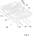
- Fig. 2
- eine zweite bevorzugte Ausführungsform der erfindungsgemäßen Textil-Vorrichtung in einer Ansicht von schräg oben.
- Fig. 1
- a first preferred embodiment of the textile device according to the invention in a view from above;
- Fig. 2
- a second preferred embodiment of the textile device according to the invention in an oblique view from above.
Die in den
Dabei ist eine mit mindestens einem Sensorfaden 130 elektrisch verbundene Steuerschaltung vorgesehen um die Intensität eines Stromflusses durch die Heizfäden 120 in Antwort auf eine gemessene Temperatur bzw. Feuchtigkeit zu steuern um für jeden gemessenen Ist-Wert einen vorherbestimmten Sollwert an Wärme in die Grundstruktur 110 einzutragen.A control circuit electrically connected to at least one
Der Heizfaden 120 und der Sensorfaden 130 sind im Bereich der gleichen Oberfläche 111 der Grundstruktur 110 angebracht.The
Die Steuerschaltung ist ausgelegt um die Intensität eines Stromflusses durch die Heizfäden 120 in Antwort auf eine gemessene Temperatur bzw. Feuchtigkeit zu steuern um in die Grundstruktur 110 für jeden gemessenen Ist-Wert einen vorherbestimmten Sollwert an Wärme einzutragen um die Grundstruktur 110 auf eine immer gleiche vorherbestimmte Temperatur zu bringen.The control circuit is designed to control the intensity of a current flow through the
Die Steuerschaltung ist des Weiteren ausgelegt um bei einem Sensorfaden 130, der bei linearem Temperaturanstieg bzw. linearem Feutigkeitsanstieg eine nicht linear verlaufenden Messkurve aufweist eine Intensität des den mindestens einen Heizfaden 120 durchfließenden Stromes zu steuern um einen derartigen Wärmeeintrag in die Grundstruktur 110 zu generieren, dass die Temperatur der Grundstruktur 110 unabhängig von der gemessenen Temperatur oder Feuchtigkeit immer konstant ist.The control circuit is also designed to control an intensity of the current flowing through the at least one
Ein Heizfaden 120 der erfindungsgemäßen Textil-Vorrichtung 100 ist von einem Karbonfaden gebildet.A
Ein Temperatur-Sensorfaden 130 ist von einem Kaltleiter mit einem positivem Temperatur-Koeffizienten (PTC-Leiter) gebildet.A
Die Grundstruktur 110 ist von einem Gewebe gebildet und sowohl der Heizfaden 120 als auch der Sensorfaden 130 sind in die Grundstruktur 110 eingewebt.The
Ein in die Grundstruktur 110 eingebrachter Heizfaden 120 ist mäanderförmig verlaufend ausgelegt, um einen möglichst großen Oberflächenbereich der Grundstruktur 110 abzudecken.A
Der in die Grundstruktur 110 eingebrachter Heizfaden 120 bildet dabei eine in sich geschlossene Schlaufe mit zwei benachbart angeordneten Enden 121, 122, wobei ein erstes Ende 121 an einen ersten Pol der ersten Spannungsquelle und ein zweites Ende 122 an den zweiten Pol der ersten Spannungsquelle anzuschließen ist.The
Die Schlaufe des Heizfadens ist in der in
Gemäß der in
Die oben erläuterten Ausführungsbeispiele der Erfindung dienen lediglich dem Zweck eines besseren Verständnisses der durch die Ansprüche vorgegebenen erfindungsgemäßen Lehre, die als solche durch die Ausführungsbeispiele nicht eingeschränkt ist.The exemplary embodiments of the invention explained above serve only the purpose of a better understanding of the teaching according to the invention specified by the claims, which as such is not restricted by the exemplary embodiments.
- 100100
- Textil-VorrichtungTextile apparatus
- 101101
- textile Fädentextile threads
- 110110
- Grundstrukturbasic structure
- 111111
- Oberflächesurface
- 112112
- Unterflächeundersurface
- 120120
- Heizfadenfilament
- 130130
- Sensorfadensensor thread
- 121121
- erstes Endefirst end
- 122122
- zweites Endesecond end
- 123123
- erster Schlaufenteilfirst loop part
- 124124
- zweiten Schlaufenteilsecond loop part
- 123'123 '
- erster Schlaufenteilfirst loop part
- 124'124 '
- zweiter Schlaufenteilsecond loop part
- 125125
- Umkehrpunktturning point
Claims (15)
Applications Claiming Priority (1)
| Application Number | Priority Date | Filing Date | Title |
|---|---|---|---|
| DE102018116474.2A DE102018116474A1 (en) | 2018-07-06 | 2018-07-06 | Heated textile device |
Publications (2)
| Publication Number | Publication Date |
|---|---|
| EP3592104A1 true EP3592104A1 (en) | 2020-01-08 |
| EP3592104B1 EP3592104B1 (en) | 2022-03-16 |
Family
ID=67180582
Family Applications (1)
| Application Number | Title | Priority Date | Filing Date |
|---|---|---|---|
| EP19184289.7A Active EP3592104B1 (en) | 2018-07-06 | 2019-07-04 | Heatable textile device |
Country Status (3)
| Country | Link |
|---|---|
| US (1) | US20200015326A1 (en) |
| EP (1) | EP3592104B1 (en) |
| DE (1) | DE102018116474A1 (en) |
Cited By (1)
| Publication number | Priority date | Publication date | Assignee | Title |
|---|---|---|---|---|
| FR3099334A1 (en) * | 2019-07-22 | 2021-01-29 | Valeo Systemes Thermiques | Heating structure for motor vehicle |
Families Citing this family (3)
| Publication number | Priority date | Publication date | Assignee | Title |
|---|---|---|---|---|
| US11267380B2 (en) * | 2018-08-03 | 2022-03-08 | Illinois Tool Works Inc. | Suspension fabric seat heating system |
| FR3116408B1 (en) * | 2020-11-19 | 2023-10-27 | Valeo Systemes Thermiques | Heating structure for motor vehicle |
| US11856661B1 (en) * | 2021-02-24 | 2023-12-26 | Automated Assembly Corporation | Flexible heating element |
Citations (2)
| Publication number | Priority date | Publication date | Assignee | Title |
|---|---|---|---|---|
| US4149066A (en) * | 1975-11-20 | 1979-04-10 | Akitoshi Niibe | Temperature controlled flexible electric heating panel |
| US20040004070A1 (en) * | 2002-07-08 | 2004-01-08 | Sunbeam Products, Inc. | Temperature sensor for a warming blanket |
Family Cites Families (6)
| Publication number | Priority date | Publication date | Assignee | Title |
|---|---|---|---|---|
| US5861610A (en) * | 1997-03-21 | 1999-01-19 | Micro Weiss Electronics | Heater wire with integral sensor wire and improved controller for same |
| WO2005089019A2 (en) * | 2004-03-08 | 2005-09-22 | W.E.T. Automotive Systems Ag | Flat heating element |
| KR20120031847A (en) * | 2010-09-27 | 2012-04-04 | 주식회사 시몬스침대 | Heating apparatus with local temperature control for bed |
| DE102013102228A1 (en) * | 2013-03-06 | 2014-09-25 | Kunert Fashion Gmbh & Co. Kg | Textile incontinence product |
| DE102015100449A1 (en) * | 2014-02-04 | 2015-08-06 | HeizTex GmbH | Surface, electrical resistance heating network |
| DE102015004004A1 (en) * | 2015-03-30 | 2016-10-06 | I.G. Bauerhin Gmbh | Heating element for user-accessible surfaces |
-
2018
- 2018-07-06 DE DE102018116474.2A patent/DE102018116474A1/en not_active Ceased
-
2019
- 2019-07-04 EP EP19184289.7A patent/EP3592104B1/en active Active
- 2019-07-08 US US16/504,708 patent/US20200015326A1/en not_active Abandoned
Patent Citations (2)
| Publication number | Priority date | Publication date | Assignee | Title |
|---|---|---|---|---|
| US4149066A (en) * | 1975-11-20 | 1979-04-10 | Akitoshi Niibe | Temperature controlled flexible electric heating panel |
| US20040004070A1 (en) * | 2002-07-08 | 2004-01-08 | Sunbeam Products, Inc. | Temperature sensor for a warming blanket |
Non-Patent Citations (1)
| Title |
|---|
| CHERENACK KUNIGUNDE ET AL: "Smart textiles: Challenges and opportunities", JOURNAL OF APPLIED PHYSICS, AMERICAN INSTITUTE OF PHYSICS, US, vol. 112, no. 9, 1 November 2012 (2012-11-01), pages 91301 - 91301, XP012167768, ISSN: 0021-8979, [retrieved on 20121107], DOI: 10.1063/1.4742728 * |
Cited By (1)
| Publication number | Priority date | Publication date | Assignee | Title |
|---|---|---|---|---|
| FR3099334A1 (en) * | 2019-07-22 | 2021-01-29 | Valeo Systemes Thermiques | Heating structure for motor vehicle |
Also Published As
| Publication number | Publication date |
|---|---|
| EP3592104B1 (en) | 2022-03-16 |
| US20200015326A1 (en) | 2020-01-09 |
| DE102018116474A1 (en) | 2020-01-09 |
Similar Documents
| Publication | Publication Date | Title |
|---|---|---|
| EP3592104A1 (en) | Heatable textile device | |
| DE958945C (en) | Flexible, wire-like, temperature-sensitive element with a device for continuous monitoring or control of an electrical circuit | |
| DE102005050459B3 (en) | Surface heating element for seat heater of motor vehicle seat, has conductor of higher conductivity running wave-like and meander-like and intersecting each of multiple steel filaments at several points | |
| EP1601235B1 (en) | Monitoring device suitable for flexible heating elements | |
| EP0009252B1 (en) | Level gauging device for a container filled at least partially with a liquid | |
| DE102014103978A1 (en) | Sensorgarn | |
| WO2008104171A1 (en) | Electric conductor | |
| DE1540765C3 (en) | Electric blanket or heating pad | |
| EP2757359B1 (en) | Apparatus for detecting leaks from a fluid conduit, in particular a high pressure liquid conduit | |
| DE102006020113A1 (en) | sensor | |
| EP3197241A1 (en) | Heating device and method for measuring the temperature on the heating element | |
| DE2032235C3 (en) | Electrical resistance heating cable | |
| DE19816816A1 (en) | Electrically heated surface heating element for heated vehicle seating or steering wheel | |
| DE69732406T2 (en) | Production method for surface heaters and surface heaters produced therewith | |
| EP3076752A1 (en) | Heating element for user-contact surfaces | |
| DE102018210036A1 (en) | Textile element and seal | |
| EP3016475B1 (en) | Device with heatable surfaces of homogeneous heat distribution | |
| DE3708945A1 (en) | INHALING DEVICE | |
| WO2015117595A1 (en) | Sheet-like, electrical resistance heating network | |
| DE1808022B2 (en) | FLEXIBLE ELECTRIC SURFACE HEATING ELEMENT | |
| DE102016122272A1 (en) | Sensor thread structure | |
| DE102008063410A1 (en) | Structural component i.e. leading edge flap, for aircraft, has base heating layer supplied with current over activation phase, so that base heating layer produces heat and auxiliary heating layers produce heat during temporal period | |
| DE102016221629B4 (en) | hot film anemometer | |
| WO1988000626A1 (en) | Contact rail for electric thread catchers | |
| DE102018119032A1 (en) | Method of making electrical contact |
Legal Events
| Date | Code | Title | Description |
|---|---|---|---|
| PUAI | Public reference made under article 153(3) epc to a published international application that has entered the european phase |
Free format text: ORIGINAL CODE: 0009012 |
|
| STAA | Information on the status of an ep patent application or granted ep patent |
Free format text: STATUS: THE APPLICATION HAS BEEN PUBLISHED |
|
| AK | Designated contracting states |
Kind code of ref document: A1 Designated state(s): AL AT BE BG CH CY CZ DE DK EE ES FI FR GB GR HR HU IE IS IT LI LT LU LV MC MK MT NL NO PL PT RO RS SE SI SK SM TR |
|
| AX | Request for extension of the european patent |
Extension state: BA ME |
|
| STAA | Information on the status of an ep patent application or granted ep patent |
Free format text: STATUS: REQUEST FOR EXAMINATION WAS MADE |
|
| 17P | Request for examination filed |
Effective date: 20200416 |
|
| STAA | Information on the status of an ep patent application or granted ep patent |
Free format text: STATUS: EXAMINATION IS IN PROGRESS |
|
| 17Q | First examination report despatched |
Effective date: 20210520 |
|
| GRAP | Despatch of communication of intention to grant a patent |
Free format text: ORIGINAL CODE: EPIDOSNIGR1 |
|
| STAA | Information on the status of an ep patent application or granted ep patent |
Free format text: STATUS: GRANT OF PATENT IS INTENDED |
|
| INTG | Intention to grant announced |
Effective date: 20211123 |
|
| GRAS | Grant fee paid |
Free format text: ORIGINAL CODE: EPIDOSNIGR3 |
|
| GRAA | (expected) grant |
Free format text: ORIGINAL CODE: 0009210 |
|
| STAA | Information on the status of an ep patent application or granted ep patent |
Free format text: STATUS: THE PATENT HAS BEEN GRANTED |
|
| AK | Designated contracting states |
Kind code of ref document: B1 Designated state(s): AL AT BE BG CH CY CZ DE DK EE ES FI FR GB GR HR HU IE IS IT LI LT LU LV MC MK MT NL NO PL PT RO RS SE SI SK SM TR |
|
| REG | Reference to a national code |
Ref country code: GB Ref legal event code: FG4D Free format text: NOT ENGLISH |
|
| REG | Reference to a national code |
Ref country code: CH Ref legal event code: EP |
|
| REG | Reference to a national code |
Ref country code: DE Ref legal event code: R096 Ref document number: 502019003703 Country of ref document: DE |
|
| REG | Reference to a national code |
Ref country code: IE Ref legal event code: FG4D Free format text: LANGUAGE OF EP DOCUMENT: GERMAN |
|
| REG | Reference to a national code |
Ref country code: AT Ref legal event code: REF Ref document number: 1476785 Country of ref document: AT Kind code of ref document: T Effective date: 20220415 |
|
| REG | Reference to a national code |
Ref country code: LT Ref legal event code: MG9D |
|
| REG | Reference to a national code |
Ref country code: NL Ref legal event code: MP Effective date: 20220316 |
|
| PG25 | Lapsed in a contracting state [announced via postgrant information from national office to epo] |
Ref country code: SE Free format text: LAPSE BECAUSE OF FAILURE TO SUBMIT A TRANSLATION OF THE DESCRIPTION OR TO PAY THE FEE WITHIN THE PRESCRIBED TIME-LIMIT Effective date: 20220316 Ref country code: RS Free format text: LAPSE BECAUSE OF FAILURE TO SUBMIT A TRANSLATION OF THE DESCRIPTION OR TO PAY THE FEE WITHIN THE PRESCRIBED TIME-LIMIT Effective date: 20220316 Ref country code: NO Free format text: LAPSE BECAUSE OF FAILURE TO SUBMIT A TRANSLATION OF THE DESCRIPTION OR TO PAY THE FEE WITHIN THE PRESCRIBED TIME-LIMIT Effective date: 20220616 Ref country code: LT Free format text: LAPSE BECAUSE OF FAILURE TO SUBMIT A TRANSLATION OF THE DESCRIPTION OR TO PAY THE FEE WITHIN THE PRESCRIBED TIME-LIMIT Effective date: 20220316 Ref country code: HR Free format text: LAPSE BECAUSE OF FAILURE TO SUBMIT A TRANSLATION OF THE DESCRIPTION OR TO PAY THE FEE WITHIN THE PRESCRIBED TIME-LIMIT Effective date: 20220316 Ref country code: BG Free format text: LAPSE BECAUSE OF FAILURE TO SUBMIT A TRANSLATION OF THE DESCRIPTION OR TO PAY THE FEE WITHIN THE PRESCRIBED TIME-LIMIT Effective date: 20220616 |
|
| PG25 | Lapsed in a contracting state [announced via postgrant information from national office to epo] |
Ref country code: LV Free format text: LAPSE BECAUSE OF FAILURE TO SUBMIT A TRANSLATION OF THE DESCRIPTION OR TO PAY THE FEE WITHIN THE PRESCRIBED TIME-LIMIT Effective date: 20220316 Ref country code: GR Free format text: LAPSE BECAUSE OF FAILURE TO SUBMIT A TRANSLATION OF THE DESCRIPTION OR TO PAY THE FEE WITHIN THE PRESCRIBED TIME-LIMIT Effective date: 20220617 Ref country code: FI Free format text: LAPSE BECAUSE OF FAILURE TO SUBMIT A TRANSLATION OF THE DESCRIPTION OR TO PAY THE FEE WITHIN THE PRESCRIBED TIME-LIMIT Effective date: 20220316 |
|
| PG25 | Lapsed in a contracting state [announced via postgrant information from national office to epo] |
Ref country code: NL Free format text: LAPSE BECAUSE OF FAILURE TO SUBMIT A TRANSLATION OF THE DESCRIPTION OR TO PAY THE FEE WITHIN THE PRESCRIBED TIME-LIMIT Effective date: 20220316 |
|
| PG25 | Lapsed in a contracting state [announced via postgrant information from national office to epo] |
Ref country code: SM Free format text: LAPSE BECAUSE OF FAILURE TO SUBMIT A TRANSLATION OF THE DESCRIPTION OR TO PAY THE FEE WITHIN THE PRESCRIBED TIME-LIMIT Effective date: 20220316 Ref country code: SK Free format text: LAPSE BECAUSE OF FAILURE TO SUBMIT A TRANSLATION OF THE DESCRIPTION OR TO PAY THE FEE WITHIN THE PRESCRIBED TIME-LIMIT Effective date: 20220316 Ref country code: RO Free format text: LAPSE BECAUSE OF FAILURE TO SUBMIT A TRANSLATION OF THE DESCRIPTION OR TO PAY THE FEE WITHIN THE PRESCRIBED TIME-LIMIT Effective date: 20220316 Ref country code: PT Free format text: LAPSE BECAUSE OF FAILURE TO SUBMIT A TRANSLATION OF THE DESCRIPTION OR TO PAY THE FEE WITHIN THE PRESCRIBED TIME-LIMIT Effective date: 20220718 Ref country code: ES Free format text: LAPSE BECAUSE OF FAILURE TO SUBMIT A TRANSLATION OF THE DESCRIPTION OR TO PAY THE FEE WITHIN THE PRESCRIBED TIME-LIMIT Effective date: 20220316 Ref country code: EE Free format text: LAPSE BECAUSE OF FAILURE TO SUBMIT A TRANSLATION OF THE DESCRIPTION OR TO PAY THE FEE WITHIN THE PRESCRIBED TIME-LIMIT Effective date: 20220316 Ref country code: CZ Free format text: LAPSE BECAUSE OF FAILURE TO SUBMIT A TRANSLATION OF THE DESCRIPTION OR TO PAY THE FEE WITHIN THE PRESCRIBED TIME-LIMIT Effective date: 20220316 |
|
| PG25 | Lapsed in a contracting state [announced via postgrant information from national office to epo] |
Ref country code: PL Free format text: LAPSE BECAUSE OF FAILURE TO SUBMIT A TRANSLATION OF THE DESCRIPTION OR TO PAY THE FEE WITHIN THE PRESCRIBED TIME-LIMIT Effective date: 20220316 Ref country code: IS Free format text: LAPSE BECAUSE OF FAILURE TO SUBMIT A TRANSLATION OF THE DESCRIPTION OR TO PAY THE FEE WITHIN THE PRESCRIBED TIME-LIMIT Effective date: 20220716 Ref country code: AL Free format text: LAPSE BECAUSE OF FAILURE TO SUBMIT A TRANSLATION OF THE DESCRIPTION OR TO PAY THE FEE WITHIN THE PRESCRIBED TIME-LIMIT Effective date: 20220316 |
|
| REG | Reference to a national code |
Ref country code: DE Ref legal event code: R097 Ref document number: 502019003703 Country of ref document: DE |
|
| PLBE | No opposition filed within time limit |
Free format text: ORIGINAL CODE: 0009261 |
|
| STAA | Information on the status of an ep patent application or granted ep patent |
Free format text: STATUS: NO OPPOSITION FILED WITHIN TIME LIMIT |
|
| PG25 | Lapsed in a contracting state [announced via postgrant information from national office to epo] |
Ref country code: DK Free format text: LAPSE BECAUSE OF FAILURE TO SUBMIT A TRANSLATION OF THE DESCRIPTION OR TO PAY THE FEE WITHIN THE PRESCRIBED TIME-LIMIT Effective date: 20220316 |
|
| REG | Reference to a national code |
Ref country code: DE Ref legal event code: R119 Ref document number: 502019003703 Country of ref document: DE |
|
| 26N | No opposition filed |
Effective date: 20221219 |
|
| PG25 | Lapsed in a contracting state [announced via postgrant information from national office to epo] |
Ref country code: SI Free format text: LAPSE BECAUSE OF FAILURE TO SUBMIT A TRANSLATION OF THE DESCRIPTION OR TO PAY THE FEE WITHIN THE PRESCRIBED TIME-LIMIT Effective date: 20220316 Ref country code: MC Free format text: LAPSE BECAUSE OF FAILURE TO SUBMIT A TRANSLATION OF THE DESCRIPTION OR TO PAY THE FEE WITHIN THE PRESCRIBED TIME-LIMIT Effective date: 20220316 |
|
| REG | Reference to a national code |
Ref country code: CH Ref legal event code: PL |
|
| REG | Reference to a national code |
Ref country code: BE Ref legal event code: MM Effective date: 20220731 |
|
| PG25 | Lapsed in a contracting state [announced via postgrant information from national office to epo] |
Ref country code: LU Free format text: LAPSE BECAUSE OF NON-PAYMENT OF DUE FEES Effective date: 20220704 Ref country code: LI Free format text: LAPSE BECAUSE OF NON-PAYMENT OF DUE FEES Effective date: 20220731 Ref country code: FR Free format text: LAPSE BECAUSE OF NON-PAYMENT OF DUE FEES Effective date: 20220731 Ref country code: CH Free format text: LAPSE BECAUSE OF NON-PAYMENT OF DUE FEES Effective date: 20220731 |
|
| PG25 | Lapsed in a contracting state [announced via postgrant information from national office to epo] |
Ref country code: DE Free format text: LAPSE BECAUSE OF NON-PAYMENT OF DUE FEES Effective date: 20230201 Ref country code: BE Free format text: LAPSE BECAUSE OF NON-PAYMENT OF DUE FEES Effective date: 20220731 |
|
| PG25 | Lapsed in a contracting state [announced via postgrant information from national office to epo] |
Ref country code: IT Free format text: LAPSE BECAUSE OF FAILURE TO SUBMIT A TRANSLATION OF THE DESCRIPTION OR TO PAY THE FEE WITHIN THE PRESCRIBED TIME-LIMIT Effective date: 20220316 Ref country code: IE Free format text: LAPSE BECAUSE OF NON-PAYMENT OF DUE FEES Effective date: 20220704 |
|
| GBPC | Gb: european patent ceased through non-payment of renewal fee |
Effective date: 20230704 |
|
| PG25 | Lapsed in a contracting state [announced via postgrant information from national office to epo] |
Ref country code: HU Free format text: LAPSE BECAUSE OF FAILURE TO SUBMIT A TRANSLATION OF THE DESCRIPTION OR TO PAY THE FEE WITHIN THE PRESCRIBED TIME-LIMIT; INVALID AB INITIO Effective date: 20190704 |