EP3591957B1 - Anordnung einer kamera an einem fahrzeug - Google Patents
Anordnung einer kamera an einem fahrzeug Download PDFInfo
- Publication number
- EP3591957B1 EP3591957B1 EP19182588.4A EP19182588A EP3591957B1 EP 3591957 B1 EP3591957 B1 EP 3591957B1 EP 19182588 A EP19182588 A EP 19182588A EP 3591957 B1 EP3591957 B1 EP 3591957B1
- Authority
- EP
- European Patent Office
- Prior art keywords
- control unit
- housing
- temperature
- vehicle
- image sensor
- Prior art date
- Legal status (The legal status is an assumption and is not a legal conclusion. Google has not performed a legal analysis and makes no representation as to the accuracy of the status listed.)
- Active
Links
Images



Classifications
-
- B—PERFORMING OPERATIONS; TRANSPORTING
- B60—VEHICLES IN GENERAL
- B60R—VEHICLES, VEHICLE FITTINGS, OR VEHICLE PARTS, NOT OTHERWISE PROVIDED FOR
- B60R11/00—Arrangements for holding or mounting articles, not otherwise provided for
- B60R11/04—Mounting of cameras operative during drive; Arrangement of controls thereof relative to the vehicle
-
- G—PHYSICS
- G03—PHOTOGRAPHY; CINEMATOGRAPHY; ANALOGOUS TECHNIQUES USING WAVES OTHER THAN OPTICAL WAVES; ELECTROGRAPHY; HOLOGRAPHY
- G03B—APPARATUS OR ARRANGEMENTS FOR TAKING PHOTOGRAPHS OR FOR PROJECTING OR VIEWING THEM; APPARATUS OR ARRANGEMENTS EMPLOYING ANALOGOUS TECHNIQUES USING WAVES OTHER THAN OPTICAL WAVES; ACCESSORIES THEREFOR
- G03B17/00—Details of cameras or camera bodies; Accessories therefor
- G03B17/02—Bodies
-
- G—PHYSICS
- G03—PHOTOGRAPHY; CINEMATOGRAPHY; ANALOGOUS TECHNIQUES USING WAVES OTHER THAN OPTICAL WAVES; ELECTROGRAPHY; HOLOGRAPHY
- G03B—APPARATUS OR ARRANGEMENTS FOR TAKING PHOTOGRAPHS OR FOR PROJECTING OR VIEWING THEM; APPARATUS OR ARRANGEMENTS EMPLOYING ANALOGOUS TECHNIQUES USING WAVES OTHER THAN OPTICAL WAVES; ACCESSORIES THEREFOR
- G03B17/00—Details of cameras or camera bodies; Accessories therefor
- G03B17/55—Details of cameras or camera bodies; Accessories therefor with provision for heating or cooling, e.g. in aircraft
-
- H—ELECTRICITY
- H04—ELECTRIC COMMUNICATION TECHNIQUE
- H04N—PICTORIAL COMMUNICATION, e.g. TELEVISION
- H04N23/00—Cameras or camera modules comprising electronic image sensors; Control thereof
- H04N23/50—Constructional details
- H04N23/52—Elements optimising image sensor operation, e.g. for electromagnetic interference [EMI] protection or temperature control by heat transfer or cooling elements
Definitions
- the invention disclosed below relates to the arrangement of a camera on a vehicle with a first temperature range and a second temperature range according to the preamble of claim 1.
- the camera includes a lens together with an image sensor and a control unit.
- a central problem when arranging a camera on a vehicle is how to cope with the different temperatures. Too high a temperature or too high a heating rate of the camera or components of the camera can lead to at least partial destruction of the camera or its components such as the control unit.
- a control unit with the arithmetic processors arranged on it is a temperature-sensitive component according to the prior art.
- heating and cooling are equated.
- heating used below is generally to be understood as an induced temperature change from an initial temperature or a comparison temperature, with no difference to cooling relevant to the disclosure of this invention.
- the concept of heating and the concept of cooling are therefore to be equated, unless otherwise stated.
- the person skilled in the art further understands that in order to control the temperature of an object or the environment around an object, the temperature of the object or the temperature of the environment must be measured.
- the person skilled in the art is able to arrange the temperature sensors required for controlling the heating device. It is known from the prior art that the control unit of the camera is arranged in a first temperature range and the lens together with the image sensor is arranged in a second temperature range, with the first temperature range and the second temperature range being separated by a vehicle body of the vehicle or an element of the vehicle .
- the image sensor and the control unit are connected to one another via a data connection according to the prior art.
- the solution known from the prior art does not represent a satisfactory solution in terms of limiting the heating rate and the temperature range with which minimum or maximum heating rate the camera or the control unit of the camera is heated or in which temperature range the camera or the control unit of the camera is heated is operated.
- the interior of a vehicle is subject to strong fluctuations, which fluctuations are caused by the lack of components with sufficient heat storage capacity and/or by the type of heat sources.
- Components with a high heat storage capacity usually have a high intrinsic weight and are therefore avoided in vehicles such as an automobile.
- Heat sources are usually arranged in vehicles, which heat sources heat the air enclosed in the interior of the vehicle directly and not indirectly via a medium with a higher heat storage capacity than air, such as a heating fluid. This causes the interior of the vehicle to heat up at heating rates which are generally harmful to the control unit.
- a heat source need not be a device, which device is designed solely to generate heat.
- the heat source may be a device, which device emits heat when in operation.
- the invention provides the solution according to claim 1.
- the solution according to the invention provides in principle that the control unit arranged in the interior of the vehicle is arranged in a housing, which housing has the thermal conductivity specified in claim 1 .
- the stated thermal conductivity coefficient ensures that with a conventional arrangement of the control unit in a vehicle, the heating caused by the heat source remains within a heating rate range, which heating rate range the person skilled in the art obtains from the manufacturer's information on the control unit.
- the invention provides that, in addition to the first temperature range and the second temperature range, a housing temperature range is created to ensure the thermal conditions such as temperature and heating rate that are permissible for the control unit.
- the temperature inside the housing is defined by the housing as an object enclosing the control unit.
- the housing thus acts as a thermal envelope extending around the control unit.
- the control unit heats up - apart from the heat caused by this itself - only occurs when the housing heats up.
- a housing with the thermal properties mentioned above is characterized in that the heat produced by the control unit during operation is dissipated by the housing to such an extent that the control unit is prevented from heating up above a maximum temperature.
- the specialist knows the maximum operating temperature from the manufacturer's specifications.
- a control unit having an operating temperature below the maximum Operating temperature can be characterized, for example, by a low energy requirement and/or by a high computing effort.
- the housing with the above thermal properties is also characterized in that the heat produced by the control unit during operation or, in particular, in the initial period of operation is only emitted to such an extent that the control unit during operation or in the initial period of operation in the Extent is heated that the control unit has or reaches a minimum temperature.
- a control unit having a minimum temperature can be characterized, for example, by a low energy requirement and/or by a high computing effort.
- control unit is heated by the heat source at a minimum heating rate, so that the control unit has a minimum temperature after a defined period of time.
- control unit can be characterized in that a control unit having the minimum temperature has special properties such as low energy consumption and/or maximum computing power.
- the solution according to the invention is further characterized in that the control unit is heated by the heat source at a maximum heating rate, so that the control unit has a temperature that is less than or equal to the maximum operating temperature.
- the effective heating rate is determined by the heat output of the heat source to the housing, with reference to conventional wisdom. Those skilled in the art can calculate and/or simulate the effective heating rate using conventional teachings. The person skilled in the art will also find the maximum heating rate in the manufacturer's specifications for the control unit.
- Temperature sensors can be arranged in the respective temperature areas, by means of which temperature sensors the temperature of the respective temperature area and/or of the elements arranged in this area can be determined.
- a heating device can subsequently be controlled by means of the temperature data measured by the temperature sensors.
- the control unit essentially comprises a circuit board with electronic components.
- selected electronic components - especially at low temperatures - may only be heated slowly in order not to damage the electronic components.
- this is opposed by the fact that at low temperatures and if the lens is icy or, equivalently, a transparent cover pane or a window, the lens must be heated up very quickly in order to enable the camera to be used as soon as possible.
- the elements of the camera device In the case of motor vehicles or trains, it is quite common for the elements of the camera device to be heated from a temperature range of minus 40° Celsius to temperatures of a few degrees plus.
- the solution shown by the disclosure of this invention provides that the objective, together with the image sensor, is arranged in a first temperature range, namely outside the vehicle body.
- the control unit is located in a second temperature range, namely inside the vehicle and also in a housing with the thermal properties specified in claim 1 and/or the thermal effect on the control unit in connection with the heat source and thus in the housing temperature range, with the image sensor and the control unit are connected by means of a suitable data connection.
- the data connection can be established by a radio connection and/or by a data cable.
- Fiber optic cables are preferably used as data cables, since fiber optic cables are suitable both for the loads in the first temperature range and for the loads in the second temperature range. The person skilled in the art is able to select further cables with sufficient data transmission, knowing the heat loads and cold loads to be expected.
- the power supply between the power supply located inside the vehicle and the image sensor located outside the vehicle must be guaranteed.
- fiber optic cables the use of fiber optic cables for power supply or the provision of a separate cable harness in a cable assembly is conceivable.
- the first temperature range and the second temperature range are specified on the one hand by the body with its insulating properties and/or by different heating of the areas and/or by the presence of other objects and their thermal properties.
- the first temperature range and the second temperature range are separated by the body with its insulating properties. This also ensures that the first temperature range is not excessively heated in the event of strong heating of the second temperature range.
- the lens and image sensor can become very hot. This is particularly desirable and/or necessary in order to prevent or resolve icing of the lens.
- the thermal properties of the objective allow the heating device to be applied directly to the object or to emit heating energy directly onto the objective.
- the interior of the vehicle, and in particular the interior of the housing generally heats up more slowly than the lens. Damage to the electronic components arranged on the control unit can be ruled out as a result.
- a camera sensor can be arranged on the control unit. If it heats up too quickly, there is a risk that cracks will appear in the camera sensor. By arranging the camera sensor inside the vehicle and the resulting gradual warming of the camera sensor, the risk of cracks forming in the camera sensor can be prevented by the arrangement according to the invention.
- the control unit can include a control unit heater, which control unit heater ensures that the control unit always has the correct temperature.
- the regulation of the temperature of the control unit may be necessary in particular if the elements separating the first temperature range and the second temperature range, such as the body of the vehicle, do not have a sufficient insulating effect, so that the heating device of one temperature range influences the other temperature range in such a way that damage occurs is to be feared for the electronic components mentioned.
- the control unit can also include ventilation or a similar device for dissipating heat.
- the housing can optionally include openings in combination with the ventilation, through which openings the heat can be dissipated from the housing.
- the provision of openings in the housing is not limited to or caused by the provision of ventilation in the housing.
- the arrangement according to the invention allows the objective, together with the image sensor, to be arranged in a further housing, which housing has minimal dimensions.
- the size of the housing can be reduced to a minimum since only the absolutely necessary elements are arranged in the further housing. Reducing the further housing to a minimum size is a long-standing desire.
- the housing volume which is usually provided for the arrangement of the control unit and which may be required for a thermal separation of heating and control is eliminated.
- Camera devices for observing the vehicle surroundings can be easily adjusted so that an image area that differs from the desired image area is recorded. This is particularly important in the case when the user does not notice the adjustment of the camera device and the recording of a changed image area.
- the user can recognize an adjustment of the mirror based on the position of the mirror. Since the position of the lens and/or the image sensor is difficult for the user to recognize in camera devices, such a check of the position of the lens, or one similar to checking the position of the mirror, is not possible when using camera devices.
- controlling the position of the camera is a problem that is independent of the arrangement of the elements such as the control device, lens, and image sensor.
- the invention also includes the note that a housing enclosing a lens and image sensor can be made very small due to the arrangement according to the invention. Due to the possible small dimensions of the housing, the user is not able to identify the position of the lens from the position of the housing.
- the image area defined by the image sensor is correctly oriented to the vehicle, i.e. the correct area of the environment is shown as the image area.
- the device according to the invention can--also independently of the above-mentioned arrangement of the elements--be characterized in that the objective includes a light source, which light source emits light into the image area of the image sensor.
- the light emitted by the light source is reflected by the body of the vehicle and/or by objects in the vicinity of the vehicle. It is an indication that the lens is misaligned when the light reflected from the object is not picked up by the image sensor's image area. The extent of the adjustment can also be estimated via the position of the reflected light.
- the reflected light can be seen as a point in the image area.
- the light can be a structured light.
- a structured light is characterized by the fact that a geometric structure is reflected on the object.
- the position and the orientation of the reflecting surface of the object in or in relation to the image area of the image sensor can be determined using methods according to the prior art by means of a geometric analysis of the structure.
- the structured light has the form of a grid, for example.
- the grid includes first rays in the light output direction and has second rays perpendicular to the first rays.
- the first rays and the second rays form squares in an undistorted state or in a so-called null state, so that the position and/or the orientation of the reflecting surface can be determined by a geometric analysis according to the prior art based on the distortion of the squares.
- the position and/or the orientation of the reflecting surface can be determined, for example, using a time-of-flight camera.
- a time-of-flight camera When using a time-of-flight camera, a light signal is emitted onto the surface by means of a light source, which light signal is reflected on the surface and recorded by the camera. Since the speed of propagation of a light signal, or light in general, becomes known, by measuring the time from when the light is emitted to when the light is received, the distance between the surface and the camera or light source can be determined.
- a light signal can be output, which light signal is reflected in a point form on the surface.
- the position of this reflection point to the camera or to of the light source is determined.
- the position and/or the geometric progression of the surface can be determined by outputting multiple light signals to multiple reflection points and determining the respective distances between reflection points and the camera or the light source or light sources.
- the camera When using a time-of-flight camera, the camera has the function of taking pictures, the further function of light output and the task of measuring the distance between the reflecting surface and the camera.
- the light source and the image sensor are integrated in the camera.
- figure 1 shows the basic arrangement of lens 1, image sensor 2 and control unit 3 of a camera device, which camera device is attached to a vehicle. It is irrelevant for the disclosure of the invention on the basis of this exemplary embodiment what type of vehicle is involved.
- the vehicle includes at the in figure 1 illustrated embodiment, a body 4, which body 4 is formed by a sandwich element.
- the sandwich element comprises flat components 5 on its surfaces and an insulating layer 6 in its central area.
- the insulation layer creates a first temperature range 11 and a second temperature range 12 when the vehicle interior 7 or the vehicle exterior 8 heats up and is therefore independent of the position of the active heating device.
- the first temperature range 11 essentially corresponds to the vehicle interior 7
- the second temperature range 12 essentially corresponds to the vehicle exterior 8 .
- the camera comprises a lens 1, an image sensor 2 arranged on the lens 1, and a control unit 3.
- the control unit 3 is arranged in the vehicle interior 7 .
- the control unit 3 is surrounded by further elements such as an interior paneling 10 of the vehicle interior 7, which interior paneling 10 usually has a high thermal storage capacity.
- the inner panel 10 acts as an enclosure within the meaning of the above disclosure of the invention. Accordingly, due to the thermal influence of the interior lining 10 on the control unit 3, the control unit 3 heats up only slowly when the vehicle interior 7 heats up.
- the vehicle interior 7, which vehicle interior 7 encloses a large volume of air, is indirectly heated mainly by a fan emitting heated air. This also leads to slow heating of the control unit 3, which is also taken into account by the arrangement of the elements of the camera according to the invention.
- the lens 1 and the image sensor 2 are arranged on the outside 8 of the vehicle.
- the lens 1 and the image sensor 2 are encased by a further housing 9 , which further housing 9 primarily has a protective function for the lens 1 and the image sensor 2 .
- the further housing 9 includes a window 13 through which window 13 images of the surroundings of the vehicle are made by means of the lens 1 and the image sensor 2 .
- the window 13 has a window heater 14 in order to prevent or reduce ice formation on the window 13 .
- figure 1 shows a conventional window heater 13, which window heater 13 comprises a heating wire applied to the surface of the window 13. The heating wire heats the window 13 directly due to the contact between the window 13 and the heating wire.
- the window 13 In order to get the window 13 free of ice or to keep it free of ice, the window 13 must be brought from temperatures of, for example, minus 40 degrees to a temperature of a few degrees plus in a short period of time.
- the person skilled in the art recognizes that such rapid heating by a large temperature difference requires an enormous heating power, which heating power can be applied by a heating wire applied to the window 13 . Due to the large heating capacity, the surrounding objects and especially the camera elements are also heated. Here, the window 13 radiates heat to the surrounding objects.
- the arrangement of the camera elements according to the invention provides that the elements of the camera elements that are insensitive to rapid heating--namely the lens and the image sensor--are arranged in the region of the heating wire and the window 13.
- the camera element that is sensitive to rapid heating--namely the control unit-- is spatially and thermally separated from the heating wire and from the window 13, which acts as a heat radiator, by the insulation layer 5 and the inner lining 10.
- the control unit 3 includes a camera sensor 15. If the camera sensor 15 heats up too quickly, there is a risk that cracks will form in the camera sensor 15, which cracks will adversely affect the functionality of the camera sensor 15.
- the control unit 3 and the image sensor 2 are connected to one another via a cable harness 16 .
- the cable harness 16 includes an optical waveguide for transmitting the data between the image sensor 2 and the control unit 3 and a power cable for the energy supply of the image sensor 2.
- the control unit 3 is connected to an energy source of the vehicle, which in figure 1 is not shown.
- the cable harness 16 is passed through an opening 17 in the body, which opening 17 is closed by the cable harness 16 and by a closure element 18 to prevent thermal convection between the temperature areas 11, 12.
- Those skilled in the art will be able to select a wire harness 16 which wire harness 16 can absorb the thermal stress caused by the wire harness 16 extending.
- the heating of the window 13 will have a thermal effect on the first interior space 11 .
- the thermal influence mentioned is reduced by the arrangement of the control unit 3 in the inner lining 10 acting as a housing.
- the interior lining satisfies the thermal properties specified in claim 1.
- control element 3 outside the further housing 9 allows the further housing 9 to be designed with minimal dimensions. This is consistent with the general requirement for the design of the camera devices, in order to be able to construct the camera devices as elements with the lowest possible air resistance when the vehicle is moving.
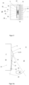
- figure 2 shows a sectional view of an application of the device according to the invention in a headlight 27.
- the shape et cetera have no particular influence on the heating of the interior of the headlight 27 and the headlight 27 as a whole during operation of the headlight 27, the headlight is 27 inches figure 2 shown only schematically. For reasons of clarity, in figure 2 no lamp et cetera of headlight 2 entered.
- the lens 1 and the image sensor 2 are arranged inside the headlight 27 . According to the prior art, the lens 1 and the image sensor 2 are insensitive to a high heating rate and to a high temperature--as occur inside the headlight 27 during operation.
- the headlight 27 An interior and an exterior and thus a first temperature range 11 in the interior and a second temperature range 12 in the exterior are defined by the headlight 27 .
- the second temperature range 12 is due to the heating by the illuminant arranged in the first temperature range 12 (in figure 2 not shown) characterized as a heat source.
- the first temperature range 11 is thermally separated from the second temperature range 12 by the headlight housing 28 .
- headlights 27 do not Headlight housing 28 with a high insulating effect, which is why the first temperature range 11 and the second temperature range 12 will behave similarly. That temperature and/or that heating rate which can be measured in the second temperature range can essentially also be measured in the first temperature range 11 .
- the arrangement of the control unit 3 in a housing 29 with the thermal properties specified in claim 1 is advantageous.
- the heating of the control unit 3 as a result of the operation of the headlight 27 can be limited to a temperature that is less than or equal to the maximum temperature of the control unit 3 .
- the heat generated by the operation of the control unit 3 can be dissipated.
- the headlight 27 shown can emit a structured light, which structured light is reflected, for example, on a substrate.
- the reflected light can be recorded using the lens 1 and the image sensor 2 .
- the correct setting of the lens 1 and/or the image sensor 2 and/or the headlight 27 with regard to the extrinsic parameters can be checked by comparing the recorded structured light with target values, as described in detail within the scope of the disclosure of the invention.
- figure 3 shows a detailed figure of a possible embodiment of a housing 29 for accommodating a control unit.
- the detailed figure does not include any dimensions, since the person skilled in the art can dimension the housing using the thermal properties mentioned in claim 1 .
- This in figure 3 Housing 29 shown is locatable adjacent or contiguous to a heating source.
- heating source not shown which heating source in figure 3 not shown is left to the in figure 3 Housing 29 shown can be arranged.
- the housing 29 shown can be connected to a headlight housing as a heating source, with the approximate position of the headlight housing being indicated here as an example of a heating source by reference number 28 in figure 3 is registered.
- the person skilled in the art can also identify sources of heating other than a headlight adjacent or adjacent to the in figure 3 Arrange housing shown.
- the casing 29 has a flat surface on its side surface facing the heating source.
- the surface facing away from the heating source comprises a plurality of ribs 30.
- the ribs 30 are suitable for forming a heat-conducting surface 31.
- the other side surfaces of the housing 29 are also designed as flat surfaces, with a design as a heat-conducting surface also being conceivable.
- the control unit 3 includes, for example, a printed circuit board 32 and an FPGA 33.
- the control unit 3 can also include other temperature-sensitive components.
- the control unit 3 is arranged at a greater distance from the side surface facing the heating source than from the cooling fin 32 . Those skilled in the art can vary this distance in view of the objectives below.
- the control unit 3 is connected to the heat-conducting surface 31 via a heat-conducting element 34 .
- the FGGA 33 and the printed circuit board 32 of the control unit 3 are connected via an intermediate piece 35 by means of soldered connections 36 .
- the distance between the circuit board 32 and the inner surface of the housing 29 is defined by spacers 35 .
- the heat 36 given off by the heating source is given off to the housing 29 in accordance with the conventional teaching.
- the housing 29 made of aluminum, for example, conducts this heat 36 to a large extent to the heat-conducting surface 31, where the heat is given off to the environment. This prevents excessive heating in the sense of heating above a temperature limit and/or in the sense of heating per unit time.
- the control unit 3 is also connected to the thermally conductive surface 31 so that the heat of the control unit 3 is dissipated via the thermally conductive surface 31 and excessive heating of the control unit 3 is thus prevented.
- the figures 4 illustrate the checking of the position of the lens 1 and the image sensor 2 to the vehicle 19. In particular, it should be checked whether the actual image area 20 with an in figure 4 non-entered target image area matches. Subsequently, the deviation can be determined.
- the camera can also include a light source 21, by means of which light source 21 a structured light is emitted.
- a structured light is emitted.
- the structured light is represented by the light beam 22 .
- the light beam 22 can be reflected from a surface in a specific position of the image area.
- the light beam 22 is reflected by the vehicle surface 23 of the vehicle 19 .
- the reflected light beam 22 is visible in the form of a point of light 24 in the image area 20 recorded by the image sensor 2 .
- the actual position of the point of light 24 can be compared with the target position of the point of light to evaluate the setting of the lens.
- Figure 4b shows the case where the camera, i.e. the lens 1, the image sensor 2 and the light source are incorrectly oriented away from the vehicle 19.
- the light beam 22 is not reflected from the vehicle surface 23 .
- a reflection of the light beam 22 on a surface of an object 25 can be determined by the reflection properties of the surface of the object 25 deviating from the reflection properties of the vehicle surface 23 .
- Figure 4c shows the case in which the camera, ie the lens 1, the image sensor 2 and the light source 22 are incorrectly oriented towards the vehicle 19. Although the light beam 22 is reflected by the vehicle surface 23, the actual position of the light spot 24 does not match the desired position, as a result of which the misalignment of the lens 1, the image sensor 2 and the light source 22 can be determined.
- figure 5 illustrates the determination of the position and/or the orientation of a surface 26 of an object 25 by the output of a structured light by a light source 21.
- the light source 21 is in turn firmly connected to the lens 1 and/or the image sensor 2.
- the light source 21 emits the light beams 22, 22', 22", which light beams 22, 22', 22" are reflected on the surface 26 of the object 25 at the points 24, 24', 24".
- the points of light 24, 24', 24'' are spaced differently by the distances d1, d2.
- the points of light 24, 24', 24" are in the image area 20, they can be recorded by the image sensor 2, so that the positions of the points of light 24, 24', 24" can be determined using the image data generated by the image sensor 2 and taking into account the above stated geometric conditions, the position and/or the inclination of the surface 26 can be determined using the current doctrine of geometry.
- the method illustrated can also include method steps, by means of which method steps the position and/or the orientation of the surface 26 is determined.
- the person skilled in the art knows such process steps according to the prior art.
Landscapes
- Physics & Mathematics (AREA)
- Engineering & Computer Science (AREA)
- General Physics & Mathematics (AREA)
- Electromagnetism (AREA)
- Multimedia (AREA)
- Signal Processing (AREA)
- Aviation & Aerospace Engineering (AREA)
- Mechanical Engineering (AREA)
- Studio Devices (AREA)
- Fittings On The Vehicle Exterior For Carrying Loads, And Devices For Holding Or Mounting Articles (AREA)
Description
- Die im Folgenden offenbarte Erfindung betrifft die Anordnung einer Kamera an einem Fahrzeug mit einem ersten Temperaturbereich und einem zweiten Temperaturbereich nach dem Oberbegriff des Anspruches 1. Die Kamera umfasst ein Objektiv mitsamt Bildsensor und eine Steuerungseinheit.
- Die Anordnung von Objektiven und Bildsensoren, mittels welcher Objektiven und Bildsensoren eine Umgebung um das Fahrzeug durch beispielsweise eine im Fahrzeuginneren befindliche Person beobachtet werden kann, und einer Steuerungseinheit zur Steuerung des Bildsensors an dem Fahrzeug ist mit der Lösung vielseitiger Problemstellungen verbunden, wobei sich die im Folgenden diskutierte Erfindung als die gemeinsame Lösung der folgenden Problemstellungen versteht.
- Ein zentrales Problem der Anordnung einer Kamera an einem Fahrzeug ist die Bewältigung der unterschiedlichen Temperaturen. Eine zu hohe Temperatur oder eine zu hohe Erwärmungsrate der Kamera oder von Komponenten der Kamera kann zu einer zumindest teilweisen Zerstörung der Kamera oder deren Komponenten wie die Steuereinheit führen. Insbesondere eine Steuereinheit mit den auf dieser angeordneten Rechenprozessoren ist nach dem Stand der Technik ein temperaturempfindliches Bauteil.
- Im Rahmen der Offenbarung der Erfindung wird der Begriff des Erwärmens und des Kühlens gleichgesetzt. Falls nichts anderes explizit angeführt ist, so ist der im Folgenden verwendete Begriff des Erwärmens allgemein als eine hervorgerufene Temperaturveränderung zu einer Anfangstemperatur oder einer Vergleichstemperatur zu verstehen, wobei kein für die Offenbarung dieser Erfindung relevanter Unterschied zu einer Kühlung besteht. Der Begriff des Erwärmens und der Begriff des Kühlens sind sohin - sofern nichts anderes angeführt ist - gleichzusetzen.
- Der Fachmann versteht weiters, dass zum Steuern der Temperatur eines Objektes oder der Umgebung um ein Objekt die Temperatur des Objektes beziehungsweise die Temperatur der Umgebung zu messen ist. Der Fachmann ist in der Lage, die zur Steuerung der Heizvorrichtung notwendigen Temperaturfühler anzuordnen. Es ist nach dem Stand der Technik bekannt, dass die Steuerungseinheit der Kamera in einem ersten Temperaturbereich und das Objektiv mitsamt Bildsensor in einem zweiten Temperaturbereich angeordnet ist, wobei der erste Temperaturbereich und der zweite Temperaturbereich durch eine Fahrzeugkarosserie des Fahrzeuges oder ein Element des Fahrzeuges getrennt sind. Der Bildsensor und die Steuerungseinheit sind über eine Datenverbindung nach dem Stand der Technik miteinander verbunden.
- Die nach dem Stand der Technik bekannte Lösung stellt allerdings keine zufriedenstellende Lösung im Sinne der Begrenzung der Erwärmungsrate und der Temperaturbereiches dar, mit welcher minimalen oder maximalen Erwärmungsrate die Kamera oder die Steuereinheit der Kamera erwärmt wird beziehungsweise in welchem Temperaturbereich die Kamera oder die Steuereinheit der Kamera betrieben wird.
- Der Innenbereich eines Fahrzeuges unterliegt starken Schwankungen, welche Schwankungen durch das Fehlen von Bauteilen mit einer ausreichenden Wärmespeicherkapazität und/oder durch die Art der Wärmequellen hervorgerufen werden.
- Bauteile mit einer hohen Wärmespeicherkapazität weisen im Regelfall ein hohes Eigengewicht auf und werden aus diesem Grund in Fahrzeugen wie beispielsweise in einem Automobil vermieden.
- In Fahrzeugen sind üblicher Weise Wärmequellen angeordnet, welche Wärmequellen die im Innenraum des Fahrzeuges eingeschlossene Luft direkt und nicht indirekt über ein Medium mit einer höheren Wärmespeicherkapazität als Luft wie beispielsweise eine Heizflüssigkeit erwärmen. Dies bedingt eine Erwärmung des Fahrzeuginneren mit Erwärmungsraten, welche Erwärmungsraten in der Regel für die Steuerungseinheit schädlich sind. Im Sinne der Offenbarung dieser Erfindung muss eine Wärmequelle nicht eine Vorrichtung sein, welche Vorrichtung ausschließlich zur Erzeugung von Wärme konzipiert ist. Die Wärmequelle kann eine Vorrichtung sein, welche Vorrichtung bei Betrieb Wärme abgibt.
- Die Dokumente
WO2017178045 ,AT400641 CN206712908 ,EP3270042 undUS10242451 - Die Erfindung sieht die Lösung gemäß Anspruch 1 vor.
- Die erfindungsgemäße Lösung sieht prinzipiell vor, dass die im Fahrzeuginneren angeordnete Steuerungseinheit in einem Gehäuse angeordnet ist, welches Gehäuse die im Anspruch 1 angegebene Wärmeleitzahl aufweist. Durch die angegebene Wärmeleitzahl wird erreicht, dass bei einer üblichen Anordnung der Steuereinheit in einem Fahrzeug die durch Wärmequelle hervorgerufene Erwärmung innerhalb einer Erwärmungsratenbereiches bleibt, welchen Erwärmungsratenbereich der Fachmann aus Herstellerangaben zu der Steuerungseinheit erhält. Die Erfindung sieht vor, dass neben dem ersten Temperaturbereich und dem zweiten Temperaturbereich ein Gehäusetemperaturbereich zur Gewährleistung der für die Steuereinheit zulässigen thermischen Verhältnisse wie Temperatur und Erwärmungsrate geschaffen wird. Die Temperatur im Gehäuseinneren wird durch das Gehäuse als ein die Steuerungseinheit umhüllender Gegenstand definiert. Das Gehäuse wirkt sohin als eine sich um die Steuerungseinheit erstreckende thermische Hülle. Eine Erwärmung der Steuerungseinheit erfolgt - abgesehen von der eigens verursachten Erwärmung - erfolgt ausschließlich unter Erwärmung des Gehäuses.
- Weiters zeichnet sich ein Gehäuse mit den oben genannten thermischen Eigenschaften dadurch aus, dass die von der Steuereinheit bei Betrieb produzierte Wärme von dem Gehäuse in einem Ausmaß von der Steuereinheit abgeführt wird, sodass eine Erwärmung der Steuereinheit über eine maximale Temperatur hinaus unterbunden wird. Der Fachmann kennt die maximale Betriebstemperatur aus den Herstellerangaben. Eine Steuereinheit aufweisend eine Betriebstemperatur unter der maximalen Betriebstemperatur kann sich beispielsweise durch einen geringen Energiebedarf und/oder durch einen hohen Rechenaufwand auszeichnen.
- Das Gehäuse mit den oben genannten thermischen Eigenschaften zeichnet sich aber auch dadurch aus, dass die von der Steuereinheit produzierte Wärme bei Betrieb oder insbesondere im Anfangszeitraum des Betriebes nur in einem solchen Ausmaß abgegeben wird, dass die Steuereinheit bei Betrieb oder im Anfangszeitraum des Betriebes in dem Ausmaß erwärmt wird, dass die Steuereinheit eine Mindesttemperatur aufweist beziehungsweise diese erreicht. Eine Steuereinheit aufweisend eine Mindesttemperatur kann sich beispielsweise durch einen geringen Energiebedarf und/oder durch einen hohen Rechenaufwand auszeichnen.
- Die erfindungsgemäße Lösung zeichnet sich auch dadurch aus, dass die Steuerungseinheit durch die Wärmequelle mit einer minimalen Erwärmungsrate erwärmt wird, sodass die Steuerungseinheit nach einer definierten Zeitspanne eine minimale Temperatur aufweist. Die Steuerungseinheit kann sich nach der gängigen Lehre dadurch auszeichnen, dass eine Steuerungseinheit aufweisend die minimale Temperatur besondere Eigenschaften wie beispielsweise einen geringen Energieverbrauch und/oder eine maximale Rechenleistung aufweist.
- Die erfindungsgemäße Lösung zeichnet sich weiters dadurch aus, dass die Steuerungseinheit durch die Wärmequelle mit einer maximalen Erwärmungsrate erwärmt wird, sodass die Steuerungseinheit eine Temperatur kleiner gleich der maximalen Betriebstemperatur aufweist.
- Die effektive Erwärmungsrate wird unter Verweis auf die gängige Lehre durch die Wärmeleistung der Wärmequelle auf das Gehäuse bestimmt. Der Fachmann kann die effektive Erwärmungsrate unter Anwendung der gängigen Lehre berechnen und/oder simulieren. Der Fachmann entnimmt weiters die maximale Erwärmungsrate den Herstellerangaben zu der Steuereinheit.
- Es können in den jeweiligen Temperaturbereichen Temperaturfühler angeordnet sein, mittels welcher Temperaturfühler die Temperatur des jeweiligen Temperaturbereiches und/oder der in diesem Bereich angeordneten Elemente bestimmbar ist. In weiterer Folge ist mittels der durch die Temperaturfühler gemessenen Temperaturdaten eine Heizvorrichtung steuerbar.
- Die Steuerungseinheit umfasst im Wesentlichen eine Platine mit elektronischen Bauteilen. Unter Verweis auf die gängige Lehre dürfen ausgewählte elektronische Bauteile - insbesondere bei tiefen Temperaturen - nur langsam erwärmt werden, um den elektronischen Bauteilen keinen Schaden zuzufügen. Dem steht jedoch entgegen, dass bei tiefen Temperaturen und bei vorliegender Vereisung des Objektivs oder gleichbedeutend hierzu einer durchsichtigen Abdeckscheibe oder eines Fensters, das Objektiv sehr rasch zu erwärmen ist, um einen ehest baldigen Gebrauch der Kamera zu ermöglichen.
- Es ist im Falle von Kraftfahrzeugen oder Zügen eine durchaus übliche Anwendung, dass die Elemente der Kameravorrichtung von einem Temperaturbereich von minus 40° Celsius auf Temperaturen von wenigen Grad Plus erwärmt werden.
- Die durch die Offenbarung dieser Erfindung aufgezeigte Lösung sieht vor, dass das Objektiv mitsamt Bildsensor in einem ersten Temperaturbereich, nämlich außerhalb der Fahrzeugkarosserie angeordnet ist. Die Steuerungseinheit ist in einem zweiten Temperaturbereich, nämlich im Fahrzeuginneren und darüber hinaus in einem Gehäuse mit den im Anspruch 1 angegebenen thermischen Eigenschaften und/oder der thermischen Wirkung auf die Steuereinheit im Zusammenhang mit der Wärmequelle und sohin in dem Gehäusetemperaturbereich angeordnet, wobei der Bildsensor und die Steuerungseinheit mittels einer geeigneten Datenverbindung verbunden sind.
- Die Datenverbindung kann durch eine Funkverbindung und/oder durch ein Datenkabel hergestellt sein. Es kommen als Datenkabel vorzugsweise Lichtwellenkabel zum Einsatz, da Lichtwellenkabel sowohl für die Belastungen im ersten Temperaturbereich als auch für die Belastungen im zweiten Temperaturbereich geeignet sind. Der Fachmann ist in der Lage, in Kenntnis der zu erwartenden Wärmebelastungen und Kältebelastungen weitere Kabel mit einer ausreichenden Datenübertragung auszuwählen.
- Bei Vorliegen einer Funkverbindung und bei einer Datenkabelverbindung ist die Stromversorgung zwischen der im Fahrzeuginneren angeordneten Stromversorgung und dem im Fahrzeugäußeren angeordneten Bildsensor zu gewährleisten. Bei der Verwendung von Lichtwellenkabeln ist die Verwendung der Lichtwellenkabel zur Stromversorgung oder das Vorsehen eines getrennten Kabelstranges in einem Kabelverbund denkbar.
- Der erste Temperaturbereich und der zweite Temperaturbereich werden nach dem Stand der Technik einerseits durch die Karosserie mit ihren dämmenden Eigenschaften und/oder durch eine unterschiedliche Beheizung der Bereiche und/oder durch die Anwesenheit von weiteren Gegenständen und deren thermischen Eigenschaften vorgegeben. Der erste Temperaturbereich und der zweite Temperaturbereich sind durch die Karosserie mit ihren dämmenden Eigenschaften getrennt. Hierdurch wird auch erreicht, dass bei einer starken Erwärmung des zweiten Temperaturbereiches der erste Temperaturbereich hierdurch nicht übermäßig erwärmt wird.
- Nach der gängigen Lehre kann das Objektiv mitsamt dem Bildsensor stark erwärmt werden. Dies wird insbesondere gewünscht und/oder ist notwendig, um eine Vereisung des Objektives zu unterbinden oder zu lösen. Die thermischen Eigenschaften des Objektives gestatten es, dass die Heizvorrichtung direkt auf das Objekt aufgebracht ist oder direkt auf das Objektiv eine Heizenergie abgibt.
- Eine Erwärmung des Fahrzeuginneren und insbesondere die Erwärmung des Gehäuseinneren erfolgt in der Regel wegen der thermischen Eigenschaften des Gehäuses langsamer als die Erwärmung des Objektivs. Eine Beschädigung der auf der Steuerungseinheit angeordneten elektronischen Komponenten kann hierdurch ausgeschlossen werden.
- Es kann insbesondere auf der Steuerungseinheit ein Kamerasensor angeordnet sein. Bei einer zu raschen Erwärmung besteht die Gefahr, dass im Kamerasensor Risse entstehen. Durch Anordnung des Kamerasensors im Fahrzeuginneren und der damit erreichten ausschließlichen allmählichen Erwärmung des Kamerasensors kann die Gefahr der Rissbildung im Kamerasensor durch die erfindungsgemäße Anordnung unterbunden werden.
- Es kann die Steuerungseinheit eine Steuerungseinheitheizung umfassen, welche Steuerungseinheitheizung sicherstellt, dass die Steuerungseinheit stets die richtige Temperatur aufweist. Die Regelung der Temperatur der Steuereinheit kann insbesondere erforderlich sein, wenn die den ersten Temperaturbereich und den zweiten Temperaturbereich trennenden Elemente wie beispielsweise die Karosserie des Fahrzeuges keine ausreichende Dämmwirkung haben, sodass durch die Heizvorrichtung des einen Temperaturbereiches der andere Temperaturbereich derart beeinflusst wird, sodass ein Schaden für die erwähnten elektronischen Bauteile zu befürchten ist.
- Es kann die Steuerungseinheit weiters eine Lüftung oder eine ähnliche Vorrichtung zur Abfuhr von Wärme umfassen. Das Gehäuse kann gegebenenfalls in Kombination mit der Lüftung Öffnungen umfassen, über welche Öffnungen die Wärme aus dem Gehäuse abgeführt werden kann. Das Vorsehen von Öffnungen im Gehäuse ist nicht auf die Anordnung einer Lüftung im Gehäuse beschränkt oder durch diese bedingt.
- Die erfindungsgemäße Anordnung erlaubt es, dass das Objektiv mitsamt dem Bildsensor in einem weiteren Gehäuse angeordnet ist, welches Gehäuse minimale Abmessungen aufweist.
- Durch die Anordnung der Steuerungseinheit in einem Gehäuse im Fahrzeuginneren und die Anordnung des Objektives mitsamt Bildsensor in einem am Fahrzeugäußeren angeordneten weitern Gehäuse kann die Größe des Gehäuses auf ein Minimum reduziert werden, da nur die unbedingt notwendigen Elemente im weiteren Gehäuse angeordnet werden. Die Reduzierung des weiteren Gehäuses auf eine minimale Größe ist ein seit langer Zeit bestehendes Verlangen.
- Im Vergleich zu Vorrichtungen nach dem Stand der Technik entfällt das für die Anordnung der Steuereinheit üblicher Weise vorgesehene und gegebenenfalls für eine thermische Trennung von Heizung und Steuerung erforderliche Gehäusevolumen.
- Kameravorrichtungen zur Beobachtung der Fahrzeugumgebung können leicht verstellt werden, sodass ein vom gewollten Bildbereich unterschiedlicher Bildbereich aufgenommen wird. Dies ist insbesondere in dem Fall von Bedeutung, wenn der Benutzer die Verstellung der Kameravorrichtung und die Aufnahme eines geänderten Bildbereiches nicht bemerkt.
- Bei einem herkömmlichen Spiegel zur Beobachtung der Fahrzeugumgebung kann der Benutzer eine Verstellung des Spiegels anhand der Stellung des Spiegels erkennen. Da bei Kameravorrichtungen die Stellung des Objektivs und/oder des Bildsensors für den Benutzer nur schwer erkennbar ist, ist eine solche oder zu der Kontrolle der Stellung des Spiegels ähnliche Überprüfung der Stellung des Objektives bei der Verwendung von Kameravorrichtungen nicht möglich.
- Im Wesentlichen ist die Kontrolle der Stellung der Kamera als ein von der Anordnung der Elemente wie Steuervorrichtung, Objektiv, Bildsensor unabhängiges Problem anzusehen. Die obige Offenbarung der Erfindung umfasst jedoch auch den Hinweis, dass ein Objektiv und Bildsensor einschließendes Gehäuse aufgrund der erfindungsgemäßen Anordnung sehr klein ausgeführt werden kann. Aufgrund der möglichen kleinen Abmessungen des Gehäuses besteht für den Benutzer auch nicht die Möglichkeit, über die Stellung des Gehäuses die Stellung des Objektivs zu erkennen.
- Bei einer Kontrolle der Stellung des Objektivs und/oder des Bildsensors ist zu überprüfen, ob der durch den Bildsensor definierte Bildbereich zum Fahrzeug richtig orientiert ist, d.h. der richtige Bereich der Umgebung als Bildbereich abgebildet ist.
- Die erfindungsgemäße Vorrichtung kann - auch unabhängig von der oben angeführten Anordnung der Elemente - sich dadurch auszeichnen, dass das Objektiv eine Lichtquelle umfasst, welche Lichtquelle ein Licht in den Bildbereich des Bildsensors abgibt.
- Das durch die Lichtquelle emittierte Licht wird durch die Karosserie des Fahrzeuges und/oder durch die in der Umgebung zu dem Fahrzeug befindlichen Gegenstände reflektiert. Es ist ein Hinweis auf eine Verstellung des Objektivs, wenn das auf dem Gegenstand reflektierte Licht nicht vom Bildbereich des Bildsensors aufgenommen wird. Über die Position des reflektierten Lichtes kann weiters das Ausmaß der Verstellung abgeschätzt werden.
- Vorzugsweise ist das reflektierte Licht als ein Punkt im Bildbereich zu sehen.
- Das Licht kann ein strukturiertes Licht sein. Ein strukturiertes Licht zeichnet sich dadurch aus, dass eine geometrische Struktur am Gegenstand reflektiert wird. Durch eine geometrische Analyse der Struktur kann die Lage und die Orientierung der reflektierenden Oberfläche des Gegenstandes im beziehungsweise zu dem Bildbereich des Bildsensors nach Verfahren nach dem Stand der Technik ermittelt werden.
- Das strukturierte Licht weist beispielsweise die Form eines Rasters auf. Das Raster umfasst erste Strahlen in Lichtausgaberichtung und weist zweite Strahlen rechtwinkelig zu den ersten Strahlen auf. Die ersten Strahlen und die zweiten Strahlen bilden in einem unverzerrten Zustand oder in einem so genannten Nullzustand Quadrate aus, sodass anhand der Verzerrung der Quadrate die Lage und/oder die Orientierung der reflektierenden Fläche durch eine geometrische Analyse nach dem Stand der Technik ermittelt werden kann.
- Die Lage und/oder die Orientierung der reflektierenden Oberfläche kann beispielsweise mittels einer time-of-flight Kamera ermittelt werden. Bei Verwendung einer time-of-flight Kamera wird mittels einer Lichtquelle ein Lichtsignal auf die Oberfläche ausgegeben, welches Lichtsignal auf der Oberfläche reflektiert und durch die Kamera aufgenommen wird. Da die Geschwindigkeit der Ausbreitung eines Lichtsignals oder von Licht im Allgemeinen bekannt wird, kann durch Messen der Zeitspanne von der Ausgabe des Lichtes bis zur Aufnahme des Lichtes die Distanz zwischen der Oberfläche und der Kamera beziehungsweise der Lichtquelle bestimmt werden.
- Es kann ein Lichtsignal ausgegeben werden, welches Lichtsignal punktförmig an der Oberfläche reflektiert wird. Hierdurch wird die Lage dieses Reflexionspunktes zu der Kamera beziehungsweise zu der Lichtquelle ermittelt. Die Lage und/oder der geometrische Verlauf der Oberfläche kann durch die Ausgabe von mehreren Lichtsignalen auf mehrere Reflexionspunkte und die Ermittlung der jeweiligen Distanzen zwischen Reflexionspunkten und der Kamera beziehungsweise der Lichtquelle oder Lichtquellen ermittelt werden.
- Bei Verwendung einer time-of-flight Kamera hat die Kamera die Funktion der Bildaufnahme, die weitere Funktion der Lichtausgabe und die Aufgabe der Distanzmessung zwischen der reflektierenden Oberfläche und der Kamera. Im Sinne der Vereinigung der Funktionen sind die Lichtquelle und der Bildsensor in der Kamera integriert.
- Die Erfindung ist weiters durch die Figuren dargestellt, wobei die Figuren folgenden Inhalt haben.
-
Figur 1 zeigt die prinzipielle Anordnung von Objektiv, Bildsensor und Steuerungseinheit für eine Außenkamera. -
Figur 2 zeigt anhand eines Schnittbildes die Anwendung der Anordnung bei einem Scheinwerfer. -
Figur 3 zeigt schematisch eine Detailfigur einer möglichen Ausführungsform eines Gehäuses zur Aufnahme einer Steuerungseinheit. -
Figur 4 veranschaulicht die Anwendung von gerichtetem Licht zur Überprüfung der Stellung des Objektivs und/oder des Bildsensors. -
Figur 5 veranschaulicht die Verwendung von strukturiertem Licht zur Ermittlung der Lage und/oder der Orientierung einer reflektierenden Oberfläche. - In den Figuren sind die nachstehenden Elemente durch die vorangestellten Bezugszeichen gekennzeichnet:
- 1
- Objektiv
- 2
- Bildsensor
- 3
- Steuerungseinheit
- 4
- Karosserie
- 5
- flächiger Bauteil
- 6
- Dämmschicht
- 7
- Fahrzeuginneres
- 8
- Fahrzeugäußeres
- 9
- Gehäuse
- 10
- Innenverkleidung
- 11
- erster Temperaturbereich
- 12
- zweiter Temperaturbereich
- 13
- Fenster
- 14
- Fensterheizung
- 15
- Kamerasensor
- 16
- Kabelstrang
- 17
- Öffnung der Karosserie
- 18
- Verschlusselement
- 19
- Fahrzeug
- 20
- Bildbereich
- 21
- Lichtquelle
- 22
- Lichtstrahl
- 23
- Fahrzeugoberfläche
- 24
- Lichtpunkt
- 25
- Gegenstand
- 26
- Oberfläche
- 27
- Scheinwerfer
- 28
- Scheinwerfergehäuse
- 29
- Gehäuse
- 30
- Rippen
- 31
- Wärmeleitfläche
- 32
- Leiterplatte
- 33
- FPGA
- 34
- Wärmeleitelement
- 35
- Abstandshalter
- 36
- Wärme
- Der Schutzumfang wird durch die Ansprüche definiert. In der Figurenbeschreibung werden lediglich anhand der Figuren mögliche Ausführungsformen diskutiert, wobei die Erfindung keinesfalls auf die diskutierten Ausführungsformen beschränkt ist. Der Fachmann ist insbesondere in der Lage die Lehre des oben angeführten allgemeinen Teils mit der Figurenbeschreibung oder die Figurenbeschreibungen zu den einzelnen Figuren miteinander zu kombinieren.
-
Figur 1 zeigt die prinzipielle Anordnung von Objektiv 1, Bildsensor 2 und Steuerungseinheit 3 einer Kameravorrichtung, welche Kameravorrichtung an einem Fahrzeug angebracht ist. Es ist hierbei ohne Bedeutung für die Offenbarung der Erfindung anhand dieses Ausführungsbeispiels, um welche Art eines Fahrzeuges es sich handelt. - Das Fahrzeug umfasst jedenfalls bei der in
Figur 1 dargestellten Ausführung eine Karosserie 4, welche Karosserie 4 durch ein Sandwichelement gebildet wird. Das Sandwichelement umfasst an seinen Oberflächen flächige Bauteile 5 und in seinem Mittenbereich eine Dämmschicht 6. Der gängigen Lehre folgend wird vor allem durch die Dämmschicht 6 eine thermische Trennung zwischen dem Fahrzeuginneren 7 und dem Fahrzeugäußeren 8 geschaffen. - Durch die Dämmschicht werden bei einer Erwärmung des Fahrzeuginneren 7 oder bei einer Erwärmung des Fahrzeugäußeren 8 und sohin unabhängig von der Position der aktiven Heizvorrichtung ein erster Temperaturbereich 11 und ein zweiter Temperaturbereich 12 geschaffen. Der erste Temperaturbereich 11 entspricht im Wesentlichen dem Fahrzeuginneren 7, während der zweite Temperaturbereich 12 im Wesentlichen dem Fahrzeugäußeren 8 entspricht.
- Die Kamera umfasst ein Objektiv 1, einen am Objektiv 1 angeordneten Bildsensor 2 und eine Steuerungseinheit 3.
- Es ist die Steuerungseinheit 3 im Fahrzeuginneren 7 angeordnet. Die Steuerungseinheit 3 ist von weiteren Elementen wie eine Innenverkleidung 10 des Fahrzeuginneren 7 umgeben, welche Innenverkleidung 10 üblicher Weise eine hohe thermische Speicherkapazität aufweist. Die Innenverkleidung 10 wirkt als ein Gehäuse im Sinne der obigen Offenbarung der Erfindung. Dementsprechend erwärmt sich aufgrund des thermischen Einflusses der Innenverkleidung 10 auf die Steuerungseinheit 3 die Steuerungseinheit 3 bei einer Erwärmung des Fahrzeuginneren 7 nur langsam.
- Üblicherweise wird das Fahrzeuginnere 7, welches Fahrzeuginnere 7 ein großes Volumen von Luft einschließt, hauptsächlich durch ein eine erwärmte Luft ausgebendes Gebläse indirekt erwärmt. Dies führt weiters zu einer langsamen Erwärmung der Steuerungseinheit 3, was ebenso durch die erfindungsgemäße Anordnung der Elemente der Kamera berücksichtigt ist.
- Das Objektiv 1 und der Bildsensor 2 sind im Fahrzeugäußeren 8 angeordnet. Das Objektiv 1 und der Bildsensor 2 sind durch ein weiteres Gehäuse 9 eingehüllt, welches weiteres Gehäuse 9 vor allem eine Schutzfunktion für das Objektiv 1 und den Bildsensor 2 hat.
- Das weitere Gehäuse 9 umfasst ein Fenster 13, durch welches Fenster 13 hindurch mittels des Objektivs 1 und des Bildsensors 2 Bildaufnahmen von der Umgebung des Fahrzeuges gemacht werden. Um einen Eisbeschlag an dem Fenster 13 zu verhindern oder abzubauen, weist das Fenster 13 eine Fensterheizung 14 auf.
Figur 1 zeigt eine übliche Fensterheizung 13, welche Fensterheizung 13 einen auf der Oberfläche des Fensters 13 aufgebrachten Heizdraht umfasst. Der Heizdraht erwärmt das Fenster 13 aufgrund des Kontaktes zwischen Fenster 13 und Heizdraht direkt. - Um das Fenster 13 eisfrei zu bekommen oder eisfrei zu halten, muss das Fenster 13 in einer kurzen Zeitspanne von Temperaturen von beispielsweise minus 40 Grad auf eine Temperatur von wenigen Grad Plus gebracht werden. Der Fachmann erkennt, dass eine solche rasche Erwärmung um eine große Temperaturdifferenz eine enorme Heizleistung erfordert, welche Heizleistung durch einen auf dem Fenster 13 aufgebrachten Heizdraht aufgebracht werden kann. Wegen der großen Heizleistung kommt es auch zu einer Erwärmung der umliegenden Objekte und insbesondere der Elemente der Kamera. Das Fenster 13 strahlt hierbei Wärme auf die umliegenden Objekte ab.
- Die erfindungsgemäße Anordnung der Kameraelemente sieht vor, dass die gegen eine rasche Erwärmung unempfindlichen Elemente der Kameraelemente - nämlich das Objektiv und der Bildsensor - im Bereich des Heizdrahtes und des Fensters 13 angeordnet sind. Das gegen eine rasche Erwärmung empfindliche Kameraelement - nämlich die Steuerungseinheit - ist durch die Dämmschicht 5 und durch die Innenverkleidung 10 vom Heizdraht und von dem als Wärmestrahler wirkenden Fenster 13 räumlich und thermisch getrennt angeordnet.
- Die Steuerungseinheit 3 umfasst einen Kamerasensor 15. Bei einer zu raschen Erwärmung des Kamerasensors 15 besteht die Gefahr, dass es im Kamerasensor 15 zu einer Rissbildung kommt, welche Risse die Funktionalität des Kamerasensors 15 negativ beeinflussen.
- Es sind die Steuerungseinheit 3 und der Bildsensor 2 über einen Kabelstrang 16 miteinander verbunden. Der Kabelstrang 16 umfasst einen Lichtwellenleiter zur Übertragung der Daten zwischen dem Bildsensor 2 und der Steuerungseinheit 3 sowie ein Stromkabel zur Energieversorgung des Bildsensors 2. Die Steuerungseinheit 3 ist mit einer Energiequelle des Fahrzeuges verbunden, was in
Figur 1 nicht dargestellt ist. Der Kabelstrang 16 wird durch eine Öffnung 17 in der Karosserie geführt, welche Öffnung 17 durch den Kabelstrang 16 und durch ein Verschlusselement 18 zur Unterbindung einer thermischen Konvektion zwischen den Temperaturbereichen 11, 12 verschlossen ist. Der Fachmann ist in der Lage, einen Kabelstrang 16 auszuwählen, welcher Kabelstrang 16 die aufgrund der Erstreckung des Kabelstranges 16 hervorgerufene thermische Belastung aufnehmen kann. - Wegen des Vorliegens der Öffnung 18 wird die Erwärmung den Fensters 13 eine thermische Auswirkung auf den ersten Innenraum 11 haben. Durch die Anordnung der Steuereinheit 3 in der als Gehäuse wirkenden Innenverkleidung 10 wird dieser erwähnte thermische Einfluss reduziert.
- Die Innenverkleidung erfüllt die im Anspruch 1 genannten thermischen Eigenschaften.
- Die Anordnung des Steuerungselementes 3 außerhalb des weiteren Gehäuses 9 erlaubt eine Ausführung des weiteren Gehäuses 9 mit minimalen Abmessungen. Dies steht im Einklang mit der allgemeinen Anforderung an die Konzeption der Kameravorrichtungen, um die Kameravorrichtungen somit als Elemente mit einem möglichst geringen Luftwiderstand bei Fahrt des Fahrzeuges ausbilden zu können.
-
Figur 2 zeigt anhand eines Schnittbildes eine Anwendung der erfindungsgemäßen Vorrichtung bei einem Scheinwerfer 27. Nachdem die Funktionsweise, die Form et cetera keinen besonderen Einfluss die bei einem Betrieb des Scheinwerfers 27 stattfindende Erwärmung des Innenraumes des Scheinwerfers 27 und des Scheinwerfers 27 als Ganzes haben, ist der Scheinwerfer 27 inFigur 2 nur schematisch dargestellt. Aus Gründen der Übersichtlichkeit ist inFigur 2 kein Leuchtmittel et cetera des Scheinwerfer 2 eingetragen. - Es ist das Objektiv 1 und der Bildsensor 2 im Inneren des Scheinwerfers 27 angeordnet. Das Objektiv 1 und der Bildsensor 2 sind nach dem Stand der Technik gegen eine hohe Erwärmungsrate und gegen eine hohe Temperatur - wie diese im Inneren des Scheinwerfers 27 beim Betrieb auftreten - unempfindlich.
- Durch den Scheinwerfer 27 wird ein Inneres und ein Äußeres und somit ein erster Temperaturbereich 11 im Inneren und ein zweiter Temperaturbereich 12 im Äußeren definiert. Der zweite Temperaturbereich 12 ist durch die Erwärmung durch das im ersten Temperaturbereich 12 angeordnete Leuchtmittel (in
Figur 2 nicht dargestellt) als Wärmequelle charakterisiert. - Der erste Temperaturbereich 11 ist vom zweiten Temperaturbereich 12 durch das Scheinwerfergehäuse 28 thermisch getrennt. Nach dem Stand der Technik weisen jedoch Scheinwerfer 27 kein Scheinwerfergehäuse 28 mit einer hohen dämmenden Wirkung auf, weshalb sich der erste Temperaturbereich 11 und der zweite Temperaturbereich 12 ähnlich verhalten werden. Jene Temperatur und/oder jene Erwärmungsrate, welche im zweiten Temperaturbereich messbar ist, ist im Wesentlichen auch im ersten Temperaturbereich 11 messbar.
- Aus diesem Grund ist die Anordnung der Steuereinheit 3 in einem Gehäuse 29 mit den in Anspruch 1 angeführten thermischen Eigenschaften vorteilhaft. Es kann die Erwärmung der Steuereinheit 3 zufolge des Betriebes des Scheinwerfers 27 auf eine Temperatur kleiner gleich der maximalen Temperatur der Steuereinheit 3 begrenzt werden. Weiters kann die durch den Betrieb der Steuereinheit 3 entstehende Wärme abgeführt werden.
- Der in
Figur 2 gezeigte Scheinwerfer 27 kann ein strukturiertes Licht ausgeben, welches strukturiertes Licht beispielsweise an einem Untergrund reflektiert wird. Das reflektierte Licht kann mittels des Objektives 1 und des Bildsensors 2 aufgenommen werden. Durch einen Vergleich des aufgenommenen strukturierten Licht mit Sollwerten kann - wie im Rahmen der Offenbarung der Erfindung im Detail beschrieben - die richtige Einstellung der des Objektives 1 und/oder des Bildsensors 2 und/oder des Scheinwerfers 27 hinsichtlich der extrinsischen Parameter kontrolliert werden. -
Figur 3 zeigt schematisch eine Detailfigur einer möglichen Ausführungsform eines Gehäuses 29 zur Aufnahme einer Steuerungseinheit. Die Detailfigur umfasst keine Bemaßung, da der Fachmann unter Heranziehung der im Anspruch 1 genannten thermischen Eigenschaften eine Dimensionierung des Gehäuses vornehmen kann. - Das in
Figur 3 gezeigte Gehäuse 29 ist benachbart oder angrenzend zu einer Erwärmungsquelle anordenbar. Die inFigur 3 nicht dargestellte Erwärmungsquelle, welche Erwärmungsquelle inFigur 3 nicht dargestellt ist, ist links zu dem inFigur 3 gezeigten Gehäuse 29 anordenbar. Das inFigur 3 gezeigte Gehäuse 29 kann an einem Scheinwerfergehäuse als Erwärmungsquelle angeschlossen sein, wobei die ungefähre Lage des Scheinwerfergehäuses als eine hier beispielhaft erwähnte Erwärmungsquelle durch das Bezugszeichen 28 inFigur 3 eingetragen ist. Der Fachmann kann auch andere Erwärmungsquellen als einen Scheinwerfer benachbart oder angrenzend zu dem inFigur 3 gezeigten Gehäuse anordnen. - Das Gehäuse 29 umfasst an seiner zu der Erwärmungsquelle gerichteten Seitenfläche eine ebene Oberfläche. Die von der Erwärmungsquelle abgewandte Oberfläche umfasst mehrere Rippen 30. Nach dem Stand der Technik sind die Rippen 30 zur Ausbildung einer Wärmeleitfläche 31 geeignet. Bei der in
Figur 3 gezeigten Ausführungsform sind die weiteren Seitenflächen des Gehäuses 29 ebenso als ebene Flächen ausgebildet, wobei auch eine Ausbildung als Wärmeleitfläche denkbar ist. - Die Steuerungseinheit 3 umfasst beispielsweise eine Leiterplatte 32 und ein FPGA 33. Die Steuerungseinheit 3 kann auch andere temperaturempfindliche Komponenten umfassen.
- Die Steuerungseinheit 3 ist in einem größeren Abstand zu der zu der Erwärmungsquelle gerichteten Seitenfläche als zu der Kühlrippe 32 angeordnet. Der Fachmann kann diesen Abstand in Anbetracht der untenstehenden Zielsetzungen abändern.
- Die Steuerungseinheit 3 ist über eine Wärmeleitelement 34 an der Wärmeleitfläche 31 angeschlossen. Der FGGA 33 und die Leiterplatte 32 der Steuerungseinheit 3 sind über ein Zwischenstück 35 mittels Lötverbindungen 36 verbunden. Der Abstand zwischen der Leiterplatte 32 und der Innenoberfläche des Gehäuses 29 ist über Abstandshalter 35 definiert.
- Die von der Erwärmungsquelle abgegebene Wärme 36 wird der gängigen Lehre folgend auf das Gehäuse 29 abgegeben. Das beispielsweise auf Aluminium hergestellte Gehäuse 29 leitet diese Wärme 36 zu einem großen Teil zu der Wärmeleitfläche 31, wo die Wärme an die Umgebung abgegeben wird. Hierdurch wird verhindert, dass eine übermäßige Erwärmung im Sinne einer Erwärmung über eine Temperaturgrenze und/oder im Sinne einer Erwärmung pro Zeiteinheit unterbunden wird.
- Die Steuereinheit 3 ist ebenso mit der Wärmeleitfläche 31 verbunden, sodass die Wärme der Steuereinheit 3 über die Wärmeleitfläche 31 abgegeben wird und so eine übermäßige Erwärmung der Steuereinheit 3 unterbunden wird.
- Die
Figuren 4 veranschaulichen die Überprüfung der Stellung des Objektives 1 und des Bildsensors 2 zu dem Fahrzeug 19. Insbesondere soll überprüft werden, ob der tatsächliche Bildbereich 20 mit einem inFigur 4 nicht eingetragenen Soll-Bildbereich übereinstimmt. In weiterer Folge kann die Abweichung bestimmt werden. - Aus Gründen der Übersichtlichkeit sind in
Figur 4 nur das Objektiv 1 und der Bildsensor 2 als Elemente der Kamera mit Bezugszeichen versehen. Die Steuerungseinheit ist aus eben diesem Grund inFigur 4 nicht eingetragen. - Die Kamera kann weiters eine Lichtquelle 21 umfassen, mittels welcher Lichtquelle 21 ein strukturiertes Licht ausgegeben wird. In
Figur 4 ist das strukturierte Licht durch den Lichtstrahl 22 dargestellt. - Gemäß einer bei der Überprüfung zu Grunde liegende und anzuwendenden Regel kann der Lichtstrahl 22 in einer bestimmten Position des Bildbereiches von einer Oberfläche reflektiert werden. Bei dem in
Figur 4a veranschaulichtem Anwendungsbeispiel wird der Lichtstrahl 22 durch die Fahrzeugoberfläche 23 des Fahrzeuges 19 reflektiert. Der reflektierte Lichtstrahl 22 ist in Form eines Lichtpunktes 24 in dem durch den Bildsensor 2 aufgenommenen Bildbereich 20 sichtbar. Die Ist-Position des Lichtpunktes 24 kann zur Bewertung der Einstellung des Objektivs mit der Soll-Position des Lichtpunktes abgeglichen werden. -
Figur 4b zeigt den Fall, dass die Kamera, sprich das Objektiv 1, der Bildsensor 2 und die Lichtquelle unrichtig vom Fahrzeug 19 weg orientiert sind. Der Lichtstrahl 22 wird nicht von der Fahrzeugoberfläche 23 reflektiert. Eine Reflexion des Lichtstrahls 22 an einer Oberfläche eines Gegenstandes 25 ist durch die von den Reflexionseigenschaften der Fahrzeugoberfläche 23 abweichenden Reflexionseigenschaften der Oberfläche des Gegenstandes 25 ermittelbar. -
Figur 4c zeigt den Fall, dass die Kamera, sprich das Objektiv 1, der Bildsensor 2 und die Lichtquelle 22 unrichtig zum Fahrzeug 19 hin orientiert sind. Der Lichtstrahl 22 wird zwar von der Fahrzeugoberfläche 23 reflektiert, jedoch stimmt die Ist-Position des Lichtpunktes 24 nicht mit der Soll-Position überein, wodurch die Fehlstellung des Objektives 1, des Bildsensors 2 und der Lichtquelle 22 ermittelbar ist. - Vorzugsweise ist - wie in den
Figuren 2 eingetragen - die Lichtquelle 21 mit dem Objektiv 1 und/oder dem Bildsensor 2 fest verbunden. -
Figur 5 veranschaulicht die Ermittlung der Lage und/oder der Orientierung einer Oberfläche 26 eines Gegenstandes 25 durch die Ausgabe eines strukturierten Lichtes durch eine Lichtquelle 21. Die Lichtquelle 21 ist wiederum fest mit dem Objektiv 1 und/oder dem Bildsensor 2 verbunden. - Die Lichtquelle 21 emittiert die Lichtstrahlen 22, 22', 22", welche Lichtstrahlen 22, 22', 22" an der Oberfläche 26 des Gegenstandes 25 an den Punkten 24, 24', 24" reflektiert werden. In Abhängigkeit der Distanz der Oberfläche 26 zu der Lichtquelle 21 und in Abhängigkeit der Neigung der Oberfläche 26 sind die Lichtpunkte 24, 24`, 24" durch die Abstände d1, d2 unterschiedlich beabstandet.
- Da die Lichtpunkte 24, 24', 24" im Bildbereich 20 liegen, sind diese mittels des Bildsensors 2 aufnehmbar, sodass anhand der über den Bildsensor 2 generierten Bilddaten die Positionen der Lichtpunkte 24, 24', 24" ermittelbar sind und unter Beachtung der oben angeführten geometrischen Verhältnisse die Lage und/oder die Neigung der Oberfläche 26 unter Anwendung der gängigen Lehre der Geometrie ermittelbar sind.
- Das durch die
Figur 5 veranschaulichte Verfahren kann auch Verfahrensschritte umfassen, mittels welchen Verfahrensschritten die Lage und/oder die Orientierung der Oberfläche 26 ermittelt wird. Der Fachmann kennt derartige Verfahrensschritte nach dem Stand der Technik.
Claims (6)
- Anordnung zum Anbringenan einem Fahrzeug umfassend einen ersten Temperaturbereich und einen zweiten Temperaturbereich,welche Anordnung eine Kamera, ein Scheinwerfergehäuse (28), ein Gehäuse (29) und eine Erwärmungsquelle umfasst,welche Kamera ein Objektiv (1) mitsamt einem Bildsensor (2) und eine mit einer maximalen Erwärmungsrate zu erwärmenden Steuerungseinheit (3) umfasst, wobei das Objektiv (1) und der Bildsensor (2) in einem Inneren des Scheinwerfergehäuses (28) und in einem durch das Innere des Scheinwerfergehäuses (28) definierten ersten Temperaturbereich (11) angeordnet sind, unddie Steuerungseinheit (3) in einem Äußeren des Scheinwerfergehäuses (28) und in einem durch das Scheinwerfergehäuse (28) definierten zweiten Temperaturbereich (12) angeordnet ist, welcher zweiter Temperaturbereich (12) mit einer in dem ersten Temperaturbereich (11) angeordneten Erwärmungsquelle erwärmbar ist,wobei der erste Temperaturbereich (11) und der zweite Temperaturbereich (12) durch das Scheinwerfergehäuse (28) und einen Teil der Fahrzeugkarosserie des Fahrzeuges getrennt sind,wobei der Bildsensor (2) und die Steuerungseinheit (3) über eine Datenverbindung verbunden sind, wobei die Steuerungseinheit (3) in dem Gehäuse (29) angeordnet ist,dadurch gekennzeichnet, dassdas Gehäuse (29) eine ebene Oberfläche an seiner zu der Erwärmungsquelle gerichteten Seitenfläche und mehrere Rippen (30) zur Ausbildung einer Wärmeleitfläche (31) an einer von Erwärmungsquelle abgewandten Oberfläche umfasst,wobei das Gehäuse (29) und die Steuerungseinheit (3) über thermisch leitende Werkstücke (34) thermisch gekoppelt sind,wobei die Steuerungseinheit (3) über thermische leitende Werkstücke (34) an der Wärmeleitfläche (31) angeschlossen ist,wobei die Steuerungseinheit (3) in einem größeren Abstand zu der Seitenfläche als zu einer Kühlrippe angeordnet ist, wobeidas Gehäuse (29) eine Wärmeleitzahl von mindestens 150,0 W/mK und/oder von maximal 250,0 W/mK aufweist, sodassdas Gehäuse innerhalb eines Erwärmungsratenbereiches umfassend eine untere Erwärmungsratenbereichsgrenze und eine obere Erwärmungsratenbereichsgrenze erwärmbar ist.
- Anordnung nach Anspruch 1, dadurch gekennzeichnet, dass
die Datenverbindung über einen Lichtwellenleiter oder über ein HD-SDI Kabel hergestellt ist. - Anordnung nach einem der Ansprüche 1 bis 2, dadurch gekennzeichnet, dass der Scheinwerfer eine Erwärmungsquelle ist.
- Anordnung nach einem der Ansprüche 1 bis 3,
dadurch gekennzeichnet, dassdie Anordnung einen Temperaturfühler umfasst, welcher Temperaturfühler in den jeweiligen Temperaturbereichen zur Bestimmung der Temperaturdes Temperaturbereiches und/oder der in den jeweiligen Temperaturbereichen angeordneten Elemente angeordnet ist. - Anordnung nach einem der Ansprüche 1 bis 4,
dadurch gekennzeichnet, dass
das Objektiv (1) eine Lichtquelle umfasst, welche Lichtquelle ein Licht in den Bildbereich des Bildsensors abgibt. - Anordnung nach Anspruch 5, dadurch gekennzeichnet, dass das Licht ein strukturiertes Licht ist.
Priority Applications (1)
| Application Number | Priority Date | Filing Date | Title |
|---|---|---|---|
| SI201930622T SI3591957T1 (sl) | 2018-07-02 | 2019-06-26 | Sestav kamere na vozilu |
Applications Claiming Priority (1)
| Application Number | Priority Date | Filing Date | Title |
|---|---|---|---|
| DE202018103760.9U DE202018103760U1 (de) | 2018-07-02 | 2018-07-02 | Anordnung einer Kamera an einem Fahrzeug |
Publications (2)
| Publication Number | Publication Date |
|---|---|
| EP3591957A1 EP3591957A1 (de) | 2020-01-08 |
| EP3591957B1 true EP3591957B1 (de) | 2023-07-19 |
Family
ID=63259310
Family Applications (1)
| Application Number | Title | Priority Date | Filing Date |
|---|---|---|---|
| EP19182588.4A Active EP3591957B1 (de) | 2018-07-02 | 2019-06-26 | Anordnung einer kamera an einem fahrzeug |
Country Status (7)
| Country | Link |
|---|---|
| EP (1) | EP3591957B1 (de) |
| DE (1) | DE202018103760U1 (de) |
| DK (1) | DK3591957T3 (de) |
| FI (1) | FI3591957T3 (de) |
| LT (1) | LT3591957T (de) |
| PT (1) | PT3591957T (de) |
| SI (1) | SI3591957T1 (de) |
Family Cites Families (6)
| Publication number | Priority date | Publication date | Assignee | Title |
|---|---|---|---|---|
| AT400641B (de) * | 1994-04-22 | 1996-02-26 | Jeitschko Stefan | Vorrichtung zur erfassung, anzeige und aufzeichnung der geschwindigkeit eines fahrzeugs |
| JP4318571B2 (ja) * | 2004-03-18 | 2009-08-26 | ソニー株式会社 | カメラ |
| EP3443733B1 (de) * | 2016-04-13 | 2021-03-31 | Thales Alenia Space Schweiz AG | Bildgebungsvorrichtung |
| JP6214717B1 (ja) * | 2016-05-24 | 2017-10-18 | 三菱電機株式会社 | 車載カメラキャリブレーション補助装置 |
| KR101830664B1 (ko) * | 2016-07-08 | 2018-02-21 | 엘지전자 주식회사 | 차량에 구비된 제어장치 및 이의 제어방법 |
| CN206712908U (zh) * | 2016-12-10 | 2017-12-05 | 东莞圣讯电子科技有限公司 | 一种新型全景监控摄像头 |
-
2018
- 2018-07-02 DE DE202018103760.9U patent/DE202018103760U1/de active Active
-
2019
- 2019-06-26 SI SI201930622T patent/SI3591957T1/sl unknown
- 2019-06-26 FI FIEP19182588.4T patent/FI3591957T3/fi active
- 2019-06-26 EP EP19182588.4A patent/EP3591957B1/de active Active
- 2019-06-26 LT LTEP19182588.4T patent/LT3591957T/lt unknown
- 2019-06-26 PT PT191825884T patent/PT3591957T/pt unknown
- 2019-06-26 DK DK19182588.4T patent/DK3591957T3/da active
Also Published As
| Publication number | Publication date |
|---|---|
| LT3591957T (lt) | 2023-09-11 |
| EP3591957A1 (de) | 2020-01-08 |
| SI3591957T1 (sl) | 2023-11-30 |
| DE202018103760U1 (de) | 2018-08-06 |
| PT3591957T (pt) | 2023-09-19 |
| DK3591957T3 (da) | 2023-10-23 |
| FI3591957T3 (fi) | 2023-10-09 |
Similar Documents
| Publication | Publication Date | Title |
|---|---|---|
| DE2737345C2 (de) | Halbleiterlaser-Vorrichtung mit einem Peltier-Element | |
| EP1195275B1 (de) | Vorrichtung zur Ermittlung der Temperatur im Innenraum eines Fahrzeuges | |
| EP2692586A1 (de) | Außenkameravorrichtung für Fahrzeuge sowie Fahrzeug mit einer solchen Außenkameravorrichtung zur Erfassung von wenigstens einem gesetzlich vorgeschriebenen Sichtfeld | |
| DE112017006511T5 (de) | Optisches Modul | |
| DE102020213660A1 (de) | Fahrassistenzsystem für ein Fahrzeug | |
| WO2015176719A1 (de) | Assistenzsystem eines kraftfahrzeugs | |
| DE102019125434A1 (de) | Bildgebungssystem | |
| DE102012210851A1 (de) | Induktionskochgerät mit IR-Sensor | |
| EP3591957B1 (de) | Anordnung einer kamera an einem fahrzeug | |
| EP1361089B1 (de) | Verfahren und Vorrichtung zur Temperaturüberwachung eines elektrischen Heizelements | |
| DE102013214550A1 (de) | Fahrzeug mit einer Heizeinrichtung | |
| EP3399339B1 (de) | Sensoranordnung für ein kraftfahrzeug, kraftfahrzeug sowie verfahren zum betreiben einer sensoreinrichtung | |
| EP1792117A1 (de) | Fahrzeugscheinwerfer | |
| WO2020038687A1 (de) | Temperaturregulierungselement und sensoranordnung | |
| EP2930063B1 (de) | Blinkereinheit für eine einrichtung zur indirekten sicht eines fahrzeugs und einrichtung zur indirekten sicht mit einer blinkereinheit | |
| DE102018200480A1 (de) | Steuereinrichtung zum Ansteuern eines E-Motors | |
| EP2196076B1 (de) | Datenübertragungsmodul | |
| WO2016058601A1 (de) | Vorrichtung zur befestigung einer kamera an der innenseite einer fahrzeugscheibe und zur verwendung in einer derartigen vorrichtung ausgebildetes elastisches, wärmeleitendes element | |
| DE102017222086A1 (de) | Thermisch justierbare vorrichtung | |
| EP3542098B1 (de) | Kühlkörper mit variablem thermischen widerstand | |
| DE102011000101A1 (de) | Aktuator zum Betätigen einer im Bereich eines wärmeführendes Bauteils, wie einer Heißgasleitung, angeordneten Klappe | |
| DE102018117590B4 (de) | Vorrichtung zur radiometrischen Kalibrierung von Wärmebildkameras | |
| DE102018215434A1 (de) | Gargerät | |
| EP4022216B1 (de) | Verbund aus einem kraftfahrzeugscheinwerfer und einem kühlmittelkreislauf eines kraftfahrzeugs | |
| DE19629630A1 (de) | Steuergeräteanordnung mit einem elektrischen Anbaugerät |
Legal Events
| Date | Code | Title | Description |
|---|---|---|---|
| PUAI | Public reference made under article 153(3) epc to a published international application that has entered the european phase |
Free format text: ORIGINAL CODE: 0009012 |
|
| STAA | Information on the status of an ep patent application or granted ep patent |
Free format text: STATUS: THE APPLICATION HAS BEEN PUBLISHED |
|
| AK | Designated contracting states |
Kind code of ref document: A1 Designated state(s): AL AT BE BG CH CY CZ DE DK EE ES FI FR GB GR HR HU IE IS IT LI LT LU LV MC MK MT NL NO PL PT RO RS SE SI SK SM TR |
|
| AX | Request for extension of the european patent |
Extension state: BA ME |
|
| STAA | Information on the status of an ep patent application or granted ep patent |
Free format text: STATUS: REQUEST FOR EXAMINATION WAS MADE |
|
| 17P | Request for examination filed |
Effective date: 20200703 |
|
| RBV | Designated contracting states (corrected) |
Designated state(s): AL AT BE BG CH CY CZ DE DK EE ES FI FR GB GR HR HU IE IS IT LI LT LU LV MC MK MT NL NO PL PT RO RS SE SI SK SM TR |
|
| RAP1 | Party data changed (applicant data changed or rights of an application transferred) |
Owner name: EYYES GMBH |
|
| STAA | Information on the status of an ep patent application or granted ep patent |
Free format text: STATUS: EXAMINATION IS IN PROGRESS |
|
| 17Q | First examination report despatched |
Effective date: 20201117 |
|
| RAP3 | Party data changed (applicant data changed or rights of an application transferred) |
Owner name: EYYES GMBH |
|
| REG | Reference to a national code |
Ref country code: DE Ref legal event code: R079 Free format text: PREVIOUS MAIN CLASS: H04N0005225000 Ipc: H04N0023520000 Ref document number: 502019008567 Country of ref document: DE |
|
| GRAP | Despatch of communication of intention to grant a patent |
Free format text: ORIGINAL CODE: EPIDOSNIGR1 |
|
| STAA | Information on the status of an ep patent application or granted ep patent |
Free format text: STATUS: GRANT OF PATENT IS INTENDED |
|
| RIC1 | Information provided on ipc code assigned before grant |
Ipc: G03B 17/02 20060101ALI20230126BHEP Ipc: G03B 17/55 20060101ALI20230126BHEP Ipc: B60R 11/04 20060101ALI20230126BHEP Ipc: H04N 23/52 20230101AFI20230126BHEP |
|
| INTG | Intention to grant announced |
Effective date: 20230220 |
|
| GRAS | Grant fee paid |
Free format text: ORIGINAL CODE: EPIDOSNIGR3 |
|
| GRAA | (expected) grant |
Free format text: ORIGINAL CODE: 0009210 |
|
| STAA | Information on the status of an ep patent application or granted ep patent |
Free format text: STATUS: THE PATENT HAS BEEN GRANTED |
|
| P01 | Opt-out of the competence of the unified patent court (upc) registered |
Effective date: 20230606 |
|
| AK | Designated contracting states |
Kind code of ref document: B1 Designated state(s): AL AT BE BG CH CY CZ DE DK EE ES FI FR GB GR HR HU IE IS IT LI LT LU LV MC MK MT NL NO PL PT RO RS SE SI SK SM TR |
|
| REG | Reference to a national code |
Ref country code: GB Ref legal event code: FG4D Free format text: NOT ENGLISH |
|
| REG | Reference to a national code |
Ref country code: CH Ref legal event code: EP |
|
| REG | Reference to a national code |
Ref country code: DE Ref legal event code: R096 Ref document number: 502019008567 Country of ref document: DE |
|
| REG | Reference to a national code |
Ref country code: IE Ref legal event code: FG4D Free format text: LANGUAGE OF EP DOCUMENT: GERMAN |
|
| REG | Reference to a national code |
Ref country code: PT Ref legal event code: SC4A Ref document number: 3591957 Country of ref document: PT Date of ref document: 20230919 Kind code of ref document: T Free format text: AVAILABILITY OF NATIONAL TRANSLATION Effective date: 20230914 |
|
| REG | Reference to a national code |
Ref country code: FI Ref legal event code: FGE |
|
| REG | Reference to a national code |
Ref country code: DK Ref legal event code: T3 Effective date: 20231016 |
|
| REG | Reference to a national code |
Ref country code: NL Ref legal event code: FP |
|
| REG | Reference to a national code |
Ref country code: SE Ref legal event code: TRGR |
|
| REG | Reference to a national code |
Ref country code: EE Ref legal event code: FG4A Ref document number: E023608 Country of ref document: EE Effective date: 20230829 |
|
| PG25 | Lapsed in a contracting state [announced via postgrant information from national office to epo] |
Ref country code: GR Free format text: LAPSE BECAUSE OF FAILURE TO SUBMIT A TRANSLATION OF THE DESCRIPTION OR TO PAY THE FEE WITHIN THE PRESCRIBED TIME-LIMIT Effective date: 20231020 |
|
| PG25 | Lapsed in a contracting state [announced via postgrant information from national office to epo] |
Ref country code: IS Free format text: LAPSE BECAUSE OF FAILURE TO SUBMIT A TRANSLATION OF THE DESCRIPTION OR TO PAY THE FEE WITHIN THE PRESCRIBED TIME-LIMIT Effective date: 20231119 |
|
| PG25 | Lapsed in a contracting state [announced via postgrant information from national office to epo] |
Ref country code: RS Free format text: LAPSE BECAUSE OF FAILURE TO SUBMIT A TRANSLATION OF THE DESCRIPTION OR TO PAY THE FEE WITHIN THE PRESCRIBED TIME-LIMIT Effective date: 20230719 Ref country code: NO Free format text: LAPSE BECAUSE OF FAILURE TO SUBMIT A TRANSLATION OF THE DESCRIPTION OR TO PAY THE FEE WITHIN THE PRESCRIBED TIME-LIMIT Effective date: 20231019 Ref country code: IS Free format text: LAPSE BECAUSE OF FAILURE TO SUBMIT A TRANSLATION OF THE DESCRIPTION OR TO PAY THE FEE WITHIN THE PRESCRIBED TIME-LIMIT Effective date: 20231119 Ref country code: HR Free format text: LAPSE BECAUSE OF FAILURE TO SUBMIT A TRANSLATION OF THE DESCRIPTION OR TO PAY THE FEE WITHIN THE PRESCRIBED TIME-LIMIT Effective date: 20230719 Ref country code: GR Free format text: LAPSE BECAUSE OF FAILURE TO SUBMIT A TRANSLATION OF THE DESCRIPTION OR TO PAY THE FEE WITHIN THE PRESCRIBED TIME-LIMIT Effective date: 20231020 |
|
| PG25 | Lapsed in a contracting state [announced via postgrant information from national office to epo] |
Ref country code: PL Free format text: LAPSE BECAUSE OF FAILURE TO SUBMIT A TRANSLATION OF THE DESCRIPTION OR TO PAY THE FEE WITHIN THE PRESCRIBED TIME-LIMIT Effective date: 20230719 |
|
| REG | Reference to a national code |
Ref country code: DE Ref legal event code: R097 Ref document number: 502019008567 Country of ref document: DE |
|
| PG25 | Lapsed in a contracting state [announced via postgrant information from national office to epo] |
Ref country code: ES Free format text: LAPSE BECAUSE OF FAILURE TO SUBMIT A TRANSLATION OF THE DESCRIPTION OR TO PAY THE FEE WITHIN THE PRESCRIBED TIME-LIMIT Effective date: 20230719 |
|
| PG25 | Lapsed in a contracting state [announced via postgrant information from national office to epo] |
Ref country code: SM Free format text: LAPSE BECAUSE OF FAILURE TO SUBMIT A TRANSLATION OF THE DESCRIPTION OR TO PAY THE FEE WITHIN THE PRESCRIBED TIME-LIMIT Effective date: 20230719 Ref country code: RO Free format text: LAPSE BECAUSE OF FAILURE TO SUBMIT A TRANSLATION OF THE DESCRIPTION OR TO PAY THE FEE WITHIN THE PRESCRIBED TIME-LIMIT Effective date: 20230719 Ref country code: ES Free format text: LAPSE BECAUSE OF FAILURE TO SUBMIT A TRANSLATION OF THE DESCRIPTION OR TO PAY THE FEE WITHIN THE PRESCRIBED TIME-LIMIT Effective date: 20230719 Ref country code: CZ Free format text: LAPSE BECAUSE OF FAILURE TO SUBMIT A TRANSLATION OF THE DESCRIPTION OR TO PAY THE FEE WITHIN THE PRESCRIBED TIME-LIMIT Effective date: 20230719 Ref country code: SK Free format text: LAPSE BECAUSE OF FAILURE TO SUBMIT A TRANSLATION OF THE DESCRIPTION OR TO PAY THE FEE WITHIN THE PRESCRIBED TIME-LIMIT Effective date: 20230719 |
|
| PLBE | No opposition filed within time limit |
Free format text: ORIGINAL CODE: 0009261 |
|
| STAA | Information on the status of an ep patent application or granted ep patent |
Free format text: STATUS: NO OPPOSITION FILED WITHIN TIME LIMIT |
|
| 26N | No opposition filed |
Effective date: 20240422 |
|
| PGFP | Annual fee paid to national office [announced via postgrant information from national office to epo] |
Ref country code: GB Payment date: 20240621 Year of fee payment: 6 |
|
| PGFP | Annual fee paid to national office [announced via postgrant information from national office to epo] |
Ref country code: DE Payment date: 20240619 Year of fee payment: 6 |
|
| PGFP | Annual fee paid to national office [announced via postgrant information from national office to epo] |
Ref country code: DK Payment date: 20240621 Year of fee payment: 6 |
|
| PGFP | Annual fee paid to national office [announced via postgrant information from national office to epo] |
Ref country code: LU Payment date: 20240619 Year of fee payment: 6 |
|
| PGFP | Annual fee paid to national office [announced via postgrant information from national office to epo] |
Ref country code: NL Payment date: 20240619 Year of fee payment: 6 |
|
| PGFP | Annual fee paid to national office [announced via postgrant information from national office to epo] |
Ref country code: AT Payment date: 20240517 Year of fee payment: 6 |
|
| PGFP | Annual fee paid to national office [announced via postgrant information from national office to epo] |
Ref country code: FR Payment date: 20240628 Year of fee payment: 6 |
|
| PGFP | Annual fee paid to national office [announced via postgrant information from national office to epo] |
Ref country code: PT Payment date: 20240614 Year of fee payment: 6 |
|
| PGFP | Annual fee paid to national office [announced via postgrant information from national office to epo] |
Ref country code: SE Payment date: 20240619 Year of fee payment: 6 Ref country code: BE Payment date: 20240619 Year of fee payment: 6 |
|
| PGFP | Annual fee paid to national office [announced via postgrant information from national office to epo] |
Ref country code: IT Payment date: 20240625 Year of fee payment: 6 |
|
| REG | Reference to a national code |
Ref country code: LT Ref legal event code: MM4D Effective date: 20240626 |
|
| PG25 | Lapsed in a contracting state [announced via postgrant information from national office to epo] |
Ref country code: FI Free format text: LAPSE BECAUSE OF NON-PAYMENT OF DUE FEES Effective date: 20240626 |
|
| PG25 | Lapsed in a contracting state [announced via postgrant information from national office to epo] |
Ref country code: BG Free format text: LAPSE BECAUSE OF NON-PAYMENT OF DUE FEES Effective date: 20240626 |
|
| PG25 | Lapsed in a contracting state [announced via postgrant information from national office to epo] |
Ref country code: LV Free format text: LAPSE BECAUSE OF NON-PAYMENT OF DUE FEES Effective date: 20240626 |
|
| PG25 | Lapsed in a contracting state [announced via postgrant information from national office to epo] |
Ref country code: LV Free format text: LAPSE BECAUSE OF NON-PAYMENT OF DUE FEES Effective date: 20240626 Ref country code: FI Free format text: LAPSE BECAUSE OF NON-PAYMENT OF DUE FEES Effective date: 20240626 Ref country code: BG Free format text: LAPSE BECAUSE OF NON-PAYMENT OF DUE FEES Effective date: 20240626 Ref country code: MC Free format text: LAPSE BECAUSE OF FAILURE TO SUBMIT A TRANSLATION OF THE DESCRIPTION OR TO PAY THE FEE WITHIN THE PRESCRIBED TIME-LIMIT Effective date: 20230719 |
|
| REG | Reference to a national code |
Ref country code: CH Ref legal event code: PL |
|
| REG | Reference to a national code |
Ref country code: EE Ref legal event code: MM4A Ref document number: E023608 Country of ref document: EE Effective date: 20240630 |
|
| PG25 | Lapsed in a contracting state [announced via postgrant information from national office to epo] |
Ref country code: LT Free format text: LAPSE BECAUSE OF NON-PAYMENT OF DUE FEES Effective date: 20240626 |
|
| PG25 | Lapsed in a contracting state [announced via postgrant information from national office to epo] |
Ref country code: IE Free format text: LAPSE BECAUSE OF NON-PAYMENT OF DUE FEES Effective date: 20240626 |
|
| PG25 | Lapsed in a contracting state [announced via postgrant information from national office to epo] |
Ref country code: EE Free format text: LAPSE BECAUSE OF NON-PAYMENT OF DUE FEES Effective date: 20240630 Ref country code: CH Free format text: LAPSE BECAUSE OF NON-PAYMENT OF DUE FEES Effective date: 20240630 |
|
| REG | Reference to a national code |
Ref country code: SI Ref legal event code: KO00 Effective date: 20240627 |
|
| PG25 | Lapsed in a contracting state [announced via postgrant information from national office to epo] |
Ref country code: CY Free format text: LAPSE BECAUSE OF FAILURE TO SUBMIT A TRANSLATION OF THE DESCRIPTION OR TO PAY THE FEE WITHIN THE PRESCRIBED TIME-LIMIT; INVALID AB INITIO Effective date: 20190626 |
|
| REG | Reference to a national code |
Ref country code: DE Ref legal event code: R119 Ref document number: 502019008567 Country of ref document: DE |
|
| PG25 | Lapsed in a contracting state [announced via postgrant information from national office to epo] |
Ref country code: PT Free format text: LAPSE BECAUSE OF NON-PAYMENT OF DUE FEES Effective date: 20251226 |
|
| REG | Reference to a national code |
Ref country code: DK Ref legal event code: EBP Effective date: 20250630 |
|
| REG | Reference to a national code |
Ref country code: SE Ref legal event code: EUG |
|
| REG | Reference to a national code |
Ref country code: NL Ref legal event code: MM Effective date: 20250701 |
|
| REG | Reference to a national code |
Ref country code: AT Ref legal event code: MM01 Ref document number: 1590658 Country of ref document: AT Kind code of ref document: T Effective date: 20250626 |
|
| PG25 | Lapsed in a contracting state [announced via postgrant information from national office to epo] |
Ref country code: LU Free format text: LAPSE BECAUSE OF NON-PAYMENT OF DUE FEES Effective date: 20250626 |
|
| GBPC | Gb: european patent ceased through non-payment of renewal fee |
Effective date: 20250626 |
|
| REG | Reference to a national code |
Ref country code: BE Ref legal event code: MM Effective date: 20250630 |
|
| PG25 | Lapsed in a contracting state [announced via postgrant information from national office to epo] |
Ref country code: HU Free format text: LAPSE BECAUSE OF FAILURE TO SUBMIT A TRANSLATION OF THE DESCRIPTION OR TO PAY THE FEE WITHIN THE PRESCRIBED TIME-LIMIT; INVALID AB INITIO Effective date: 20190626 |
|
| PG25 | Lapsed in a contracting state [announced via postgrant information from national office to epo] |
Ref country code: NL Free format text: LAPSE BECAUSE OF NON-PAYMENT OF DUE FEES Effective date: 20250701 |
|
| PG25 | Lapsed in a contracting state [announced via postgrant information from national office to epo] |
Ref country code: GB Free format text: LAPSE BECAUSE OF NON-PAYMENT OF DUE FEES Effective date: 20250626 |
|
| PG25 | Lapsed in a contracting state [announced via postgrant information from national office to epo] |
Ref country code: DE Free format text: LAPSE BECAUSE OF NON-PAYMENT OF DUE FEES Effective date: 20260101 |
|
| PG25 | Lapsed in a contracting state [announced via postgrant information from national office to epo] |
Ref country code: AT Free format text: LAPSE BECAUSE OF NON-PAYMENT OF DUE FEES Effective date: 20250626 |
|
| PG25 | Lapsed in a contracting state [announced via postgrant information from national office to epo] |
Ref country code: BE Free format text: LAPSE BECAUSE OF NON-PAYMENT OF DUE FEES Effective date: 20250630 Ref country code: IT Free format text: LAPSE BECAUSE OF NON-PAYMENT OF DUE FEES Effective date: 20250626 |
|
| PG25 | Lapsed in a contracting state [announced via postgrant information from national office to epo] |
Ref country code: FR Free format text: LAPSE BECAUSE OF NON-PAYMENT OF DUE FEES Effective date: 20250630 |