EP3591939B1 - Method for providing paas service and management system - Google Patents
Method for providing paas service and management system Download PDFInfo
- Publication number
- EP3591939B1 EP3591939B1 EP18774532.8A EP18774532A EP3591939B1 EP 3591939 B1 EP3591939 B1 EP 3591939B1 EP 18774532 A EP18774532 A EP 18774532A EP 3591939 B1 EP3591939 B1 EP 3591939B1
- Authority
- EP
- European Patent Office
- Prior art keywords
- paas
- tenant
- management system
- iaas
- service
- Prior art date
- Legal status (The legal status is an assumption and is not a legal conclusion. Google has not performed a legal analysis and makes no representation as to the accuracy of the status listed.)
- Active
Links
Images




Classifications
-
- H—ELECTRICITY
- H04—ELECTRIC COMMUNICATION TECHNIQUE
- H04L—TRANSMISSION OF DIGITAL INFORMATION, e.g. TELEGRAPHIC COMMUNICATION
- H04L63/00—Network architectures or network communication protocols for network security
- H04L63/10—Network architectures or network communication protocols for network security for controlling access to devices or network resources
-
- H—ELECTRICITY
- H04—ELECTRIC COMMUNICATION TECHNIQUE
- H04L—TRANSMISSION OF DIGITAL INFORMATION, e.g. TELEGRAPHIC COMMUNICATION
- H04L67/00—Network arrangements or protocols for supporting network services or applications
- H04L67/50—Network services
- H04L67/60—Scheduling or organising the servicing of application requests, e.g. requests for application data transmissions using the analysis and optimisation of the required network resources
-
- G—PHYSICS
- G06—COMPUTING OR CALCULATING; COUNTING
- G06F—ELECTRIC DIGITAL DATA PROCESSING
- G06F9/00—Arrangements for program control, e.g. control units
- G06F9/06—Arrangements for program control, e.g. control units using stored programs, i.e. using an internal store of processing equipment to receive or retain programs
- G06F9/44—Arrangements for executing specific programs
- G06F9/455—Emulation; Interpretation; Software simulation, e.g. virtualisation or emulation of application or operating system execution engines
-
- G—PHYSICS
- G06—COMPUTING OR CALCULATING; COUNTING
- G06F—ELECTRIC DIGITAL DATA PROCESSING
- G06F9/00—Arrangements for program control, e.g. control units
- G06F9/06—Arrangements for program control, e.g. control units using stored programs, i.e. using an internal store of processing equipment to receive or retain programs
- G06F9/44—Arrangements for executing specific programs
- G06F9/455—Emulation; Interpretation; Software simulation, e.g. virtualisation or emulation of application or operating system execution engines
- G06F9/45504—Abstract machines for programme code execution, e.g. Java virtual machine [JVM], interpreters, emulators
-
- G—PHYSICS
- G06—COMPUTING OR CALCULATING; COUNTING
- G06F—ELECTRIC DIGITAL DATA PROCESSING
- G06F9/00—Arrangements for program control, e.g. control units
- G06F9/06—Arrangements for program control, e.g. control units using stored programs, i.e. using an internal store of processing equipment to receive or retain programs
- G06F9/44—Arrangements for executing specific programs
- G06F9/455—Emulation; Interpretation; Software simulation, e.g. virtualisation or emulation of application or operating system execution engines
- G06F9/45533—Hypervisors; Virtual machine monitors
- G06F9/45558—Hypervisor-specific management and integration aspects
-
- G—PHYSICS
- G06—COMPUTING OR CALCULATING; COUNTING
- G06F—ELECTRIC DIGITAL DATA PROCESSING
- G06F9/00—Arrangements for program control, e.g. control units
- G06F9/06—Arrangements for program control, e.g. control units using stored programs, i.e. using an internal store of processing equipment to receive or retain programs
- G06F9/46—Multiprogramming arrangements
- G06F9/50—Allocation of resources, e.g. of the central processing unit [CPU]
- G06F9/5061—Partitioning or combining of resources
- G06F9/5077—Logical partitioning of resources; Management or configuration of virtualized resources
-
- H—ELECTRICITY
- H04—ELECTRIC COMMUNICATION TECHNIQUE
- H04L—TRANSMISSION OF DIGITAL INFORMATION, e.g. TELEGRAPHIC COMMUNICATION
- H04L41/00—Arrangements for maintenance, administration or management of data switching networks, e.g. of packet switching networks
- H04L41/50—Network service management, e.g. ensuring proper service fulfilment according to agreements
-
- H—ELECTRICITY
- H04—ELECTRIC COMMUNICATION TECHNIQUE
- H04L—TRANSMISSION OF DIGITAL INFORMATION, e.g. TELEGRAPHIC COMMUNICATION
- H04L63/00—Network architectures or network communication protocols for network security
- H04L63/08—Network architectures or network communication protocols for network security for authentication of entities
- H04L63/0853—Network architectures or network communication protocols for network security for authentication of entities using an additional device, e.g. smartcard, SIM or a different communication terminal
-
- H—ELECTRICITY
- H04—ELECTRIC COMMUNICATION TECHNIQUE
- H04L—TRANSMISSION OF DIGITAL INFORMATION, e.g. TELEGRAPHIC COMMUNICATION
- H04L67/00—Network arrangements or protocols for supporting network services or applications
- H04L67/01—Protocols
- H04L67/10—Protocols in which an application is distributed across nodes in the network
-
- H—ELECTRICITY
- H04—ELECTRIC COMMUNICATION TECHNIQUE
- H04L—TRANSMISSION OF DIGITAL INFORMATION, e.g. TELEGRAPHIC COMMUNICATION
- H04L67/00—Network arrangements or protocols for supporting network services or applications
- H04L67/50—Network services
- H04L67/51—Discovery or management thereof, e.g. service location protocol [SLP] or web services
-
- H—ELECTRICITY
- H04—ELECTRIC COMMUNICATION TECHNIQUE
- H04L—TRANSMISSION OF DIGITAL INFORMATION, e.g. TELEGRAPHIC COMMUNICATION
- H04L67/00—Network arrangements or protocols for supporting network services or applications
- H04L67/50—Network services
- H04L67/56—Provisioning of proxy services
-
- G—PHYSICS
- G06—COMPUTING OR CALCULATING; COUNTING
- G06F—ELECTRIC DIGITAL DATA PROCESSING
- G06F9/00—Arrangements for program control, e.g. control units
- G06F9/06—Arrangements for program control, e.g. control units using stored programs, i.e. using an internal store of processing equipment to receive or retain programs
- G06F9/44—Arrangements for executing specific programs
- G06F9/455—Emulation; Interpretation; Software simulation, e.g. virtualisation or emulation of application or operating system execution engines
- G06F9/45533—Hypervisors; Virtual machine monitors
- G06F9/45558—Hypervisor-specific management and integration aspects
- G06F2009/45595—Network integration; Enabling network access in virtual machine instances
Definitions
- This application relates to the field of cloud computing services, and more specifically, to a method for providing a platform as a service (PaaS) service, and a platform as a service PaaS management system.
- PaaS platform as a service
- services provided by a cloud computing service architecture for a user usually include an infrastructure as a service (IaaS) service, a platform as a service (PaaS) service, a software as a service (SaaS) service, and the like.
- IaaS infrastructure as a service
- PaaS platform as a service
- SaaS software as a service
- the IaaS service manages an infrastructure resource of the user, for example, at least one of infrastructure resources such as a central processing unit (Central Processing Unit, CPU), a memory, a storage medium, a network, and a router (router), and the infrastructure resource of the user includes an infrastructure resource of a software service provided for running the PaaS service.
- the PaaS service is based on the IaaS service, and the PaaS service deploys a common software service on an infrastructure resource provided by the IaaS service. Therefore, both the PaaS service and the IaaS service can manage infrastructure resources together, and consequently a conflict occurs between management performed by the PaaS service and management performed by the IaaS service.
- a resource management system can receive a request for a service.
- a request may indicate preferences for allocation resources (e.g., a resource definition) to enable the service.
- a resource definition may indicate a topology of the computing resources to allocate for the user. The topology may indicate what computing resources to allocate and how to allocate those computing resource.
- the resource management system may determine a placement policy for allocation of computing resources indicated by the request.
- a placement policy may indicate a placement of one or more computing resources requested by a user. The placement policy may indicate where and how computing resources are to be placed once allocated. The computing resources may be allocated based on the placement policy and the resource definition.
- This application provides a method for providing a PaaS service and a platform as a service PaaS management system, so that not only a multi-tenant requirement is met, but also a conflict problem existing between infrastructure resource management performed by an IaaS service and infrastructure resource management performed by a PaaS service can be resolved.
- services provided by a cloud computing service architecture for a user usually include an Infrastructure as a Service ( IaaS) service, a Platform as a Service ( PaaS) service, a Software as a Service (SaaS) service, and the like.
- IaaS Infrastructure as a Service
- PaaS Platform as a Service
- SaaS Software as a Service
- the IaaS service provides, in a form of a service, the user with permission to use at least one of infrastructure resources such as a CPU, a memory, a storage medium, a network, and a router.
- infrastructure resources such as a CPU, a memory, a storage medium, a network, and a router.
- the user does not need to care about or manage any specific hardware resource, and the service saves a place and manpower and reduces maintenance costs.
- the IaaS service provides pay-as-you-grow convenience and subscribe-and-use convenience for the user, significantly improving flexibility of managing information technology (Information Technology, IT) infrastructure resources by the user.
- Information Technology, IT Information Technology
- the PaaS service provides the user with an IaaS service-based software platform in a form of a service.
- the PaaS service invokes a hardware resource by using an Application Programming Interface (API) provided by the IaaS service.
- API Application Programming Interface
- the hardware resource integrates with a common software business capability, to provide the user with complete infrastructure resource application services, for example, a database service, a messaging service, and a cache service.
- API Application Programming Interface
- the PaaS service the user can focus more on a software service on an application software platform, without paying attention to application, expansion, and maintenance of infrastructure resources.
- the SaaS service is a mode in which a software service is provided by using the Internet.
- a vendor deploys all software on a server of the vendor. The user may subscribe to a required software service from the vendor based on an actual requirement of the user by using the Internet.
- a multi-tenancy technology or referred to as a multi-leasing technology, is a software architecture technology.
- the multi-tenancy technology explores and implements how to share a same system or program component in a multi-tenant environment while still ensuring data isolation between tenants.
- the multi-tenancy technology is widely used in the SaaS service and the IaaS service, and becomes a key technology of the SaaS service.
- the multi-tenancy technology is generally divided into different categories by isolation degree: a hardware virtualization multi-tenancy technology, a database isolation multi-tenancy technology, a database sharing multi-tenancy technology, and the like.
- a hardware virtualization multi-tenancy technology e.g., a hardware virtualization multi-tenancy technology
- a database isolation multi-tenancy technology e.g., a database sharing multi-tenancy technology
- the multi-tenancy technology may be further divided into categories such as a hardware sharing multi-tenancy technology, an operating system (Operating System, OS) sharing multi-tenancy technology, a database sharing multi-tenancy technology, and an everything sharing multi-tenancy technology.
- OS Operating System
- a hardware sharing method is selected to implement the multi-tenancy technology for most IaaS services for the following reasons: First, a hardware virtualization technology is mature and of moderate difficulty, and second, hardware virtualization accords with an idea of the IaaS service.
- the SaaS service has an obvious commonality in user requirements because businesses of the SaaS service are highly consistent, in other words, the provided businesses are oriented to a specific field. Most of companies with a profound data sharing capability, for example, Google, select the everything sharing multi-tenancy technology.
- the IaaS service manages an infrastructure resource of the user, for example, at least one of infrastructure resources such as a CPU, a memory, a storage medium, a network, and a router, and the infrastructure resource of the user includes an infrastructure resource of a software service provided for running the PaaS service.
- the PaaS service is based on the IaaS service, and the PaaS service deploys a common software service on an infrastructure resource provided by the IaaS service.
- both the PaaS service and the IaaS service can manage infrastructure resources together, and consequently a conflict occurs between management performed by the PaaS service and management performed by the IaaS service.
- the infrastructure resource of the software service provided for running the PaaS service can be deleted on a service page of the IaaS service.
- a network policy of the IaaS service may affect internal communication of the PaaS service.
- the PaaS service provides the user only with a service address and a port.
- an infrastructure resource corresponding to the PaaS service is exposed to the user in an IaaS management system.
- the user needs to care about resulting problems, for example, port security and a firewall access rule.
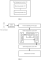
- FIG. 1 is a schematic block diagram of a PaaS management system 100 according to an embodiment of this application.
- the PaaS management system 100 may include:
- a cloud computing service architecture may provide a PaaS service for the first real tenant by using the PaaS management system 100 in this embodiment of this application.
- the cloud computing service architecture may provide an IaaS service for the first real tenant by using the IaaS management system.
- the receiving module 110 in the PaaS management system 100 may specifically include a PaaS tenant service component that is configured to interact with a real tenant.
- the processing module 120 may specifically include some functions of the PaaS tenant service component, a virtual tenant resource pool component that manages the one-to-one correspondences between real tenants and virtual tenants, and a PaaS tenant proxy component that is used as a proxy for the real tenant to perform an IaaS operation.
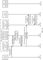
- FIG. 2 is a schematic block diagram of an application PaaS management system 200 according to an embodiment of this application.
- the PaaS management system 200 is a management system of a cloud computing service architecture at a platform (Platform, P) layer.
- the PaaS management system is a management system configured to process a PaaS operation in the cloud computing service architecture.
- An IaaS management system 300 is a management system of the cloud computing service architecture at an infrastructure (Infrastructure, I) layer.
- the IaaS management system is a management system configured to process an IaaS operation in the cloud computing service architecture.
- the cloud computing service architecture For a tenant, for example, a first real tenant, the cloud computing service architecture provides a PaaS service for the first real tenant by using the PaaS management system 200. In addition, the cloud computing service architecture may also provide an IaaS service for the first real tenant by using the IaaS management system 300. However, this is not limited in this embodiment of this application.
- the PaaS management system 200 shown in FIG. 2 includes a PaaS tenant service component 210, a virtual tenant resource pool component 220, and a PaaS tenant proxy component 230.
- the PaaS tenant service component 210 is configured to receive a PaaS operation request sent by the first real tenant to the PaaS management system 200.
- the PaaS operation request is used to indicate a PaaS operation intended for a PaaS resource.
- the PaaS resource is an infrastructure resource and a software resource on the infrastructure resource.
- the PaaS tenant service component 210 is configured to interact with a real tenant and respond to a PaaS operation request from the real tenant.
- the PaaS tenant service component 210 may be an application deployed in a web (web) container of the infrastructure resource, and provide an interface for a cloud computing service page in an HTTP form.
- the real tenant may send the PaaS operation request to the PaaS tenant service component 210 by using the cloud computing service page.
- the PaaS tenant service component 210 responds to the PaaS operation request and processes a related PaaS operation, for example, applying for a PaaS instance, restarting a PaaS instance, changing a PaaS instance, or deleting a PaaS instance.
- the PaaS tenant service component 210 is further configured to interact with the virtual tenant resource pool component 220 and the PaaS tenant proxy component 230, to perform the PaaS operation for the real tenant.
- the PaaS tenant service component 210 requests a first virtual tenant corresponding to the first real tenant from the virtual tenant resource pool component 220.
- the PaaS tenant service component 210 further performs corresponding processing, and separates an IaaS operation corresponding to the PaaS operation indicated by the PaaS operation request, so that the PaaS tenant proxy component 230 performs the IaaS operation subsequently.
- the PaaS tenant service component 210 may perform logic such as necessary authentication and a necessary security check by using an identity and access management (IAM) component.
- IAM identity and access management
- the virtual tenant resource pool component 220 is configured to manage one-to-one correspondences between real tenants and virtual tenants.
- the first real tenant and the first virtual tenant are a pair in the one-to-one correspondences.
- the virtual tenant resource pool component 220 is further configured to send information about the first virtual tenant to the PaaS tenant service component 210.
- the virtual tenant resource pool component 220 may also be a built-in component, and interacts with the PaaS tenant service component 210 in a form of a program interface. Both the virtual tenant resource pool component 220 and the PaaS tenant service component 210 are deployed in a same application of a same web container.
- the cloud computing service architecture may preset a plurality of virtual tenants to form a resource pool that is stored in the virtual tenant resource pool component 220 for use.
- the PaaS tenant service component 210 initiates an invocation of virtual tenant selection to the virtual tenant resource pool component 220.
- the virtual tenant resource pool component 220 allocates an unoccupied virtual tenant to the real tenant from an internal resource pool, records a correspondence between the real tenant and the virtual tenant, and returns information about the virtual tenant to the PaaS tenant service component 210.
- the virtual tenant resource pool component 220 After allocating a virtual tenant to each real tenant, the virtual tenant resource pool component 220 records correspondences between real tenants and virtual tenants one by one. In a subsequent PaaS operation request process (for example, when a real tenant re-applies for, changes, or deletes a PaaS instance), the virtual tenant resource pool component 220 directly returns information about a corresponding virtual tenant to the PaaS tenant service component 210.
- the real tenant in the embodiments of this application is a tenant who leases the PaaS service and who can initiate a PaaS operation request by using the PaaS management system.
- the real tenant does not have permission to manage an infrastructure resource finally corresponding to the PaaS operation request.
- the real tenant does not have permission to manage, by using the IaaS management system, the infrastructure resource corresponding to the PaaS operation request.
- the real tenant may be a tenant who leases the IaaS service and who can initiate an IaaS operation request by using the IaaS management system.
- the real tenant has permission to manage an infrastructure resource corresponding to the IaaS operation request initiated by the real tenant by using the IaaS management system.
- the real tenant is registered by a user in the PaaS management system.
- the user may set a user name and a password for identity authentication performed by the PaaS management system, so that the user can log in to the PaaS management system to use the PaaS service.
- the virtual tenant is not a tenant who actually exists, but a tenant that is allocated to the real tenant by the PaaS management system, that is used as a proxy for the real tenant, and that has permission to manage the infrastructure resource corresponding to the PaaS operation request.
- the virtual tenant has permission to manage, by using the IaaS management system, the infrastructure resource corresponding to the PaaS operation request.
- the virtual tenant is an ID or a number allocated by the PaaS management system to a registered real tenant.
- the virtual tenant does not have permission to manage the infrastructure resource corresponding to the IaaS operation request initiated by the real tenant by using the IaaS management system.
- the real tenant and the virtual tenant are two different tenants, and the IaaS management system isolates management permission of the real tenant from that of the virtual tenant.
- the PaaS tenant proxy component 230 is configured to receive the information about the first virtual tenant and related information of the IaaS operation corresponding to the PaaS operation that are sent by the PaaS tenant service component 210, work as a proxy for the first real tenant by using the first virtual tenant, and control the IaaS management system 300 to process the IaaS operation corresponding to the PaaS operation.
- the PaaS tenant proxy component 230 mainly performs identity proxy work for the real tenant, and controls, with a proxy identity of the real tenant, the IaaS management system 300 to manage a corresponding infrastructure resource.
- the virtual tenant resource pool component 220 sends the information about the first virtual tenant to the PaaS tenant service component 210.
- the PaaS tenant service component 210 sends the information about the first virtual tenant and the related information of the IaaS operation corresponding to the PaaS operation to the PaaS tenant proxy component 230.
- the PaaS tenant proxy component 230 works as the proxy for the first real tenant by using the first virtual tenant, and controls the IaaS management system 300 to process the IaaS operation corresponding to the PaaS operation, for example, create a Virtual Machine (VM) (that is, create a PaaS instance), change a VM resource, or delete a VM resource.
- VM Virtual Machine
- the PaaS tenant proxy component 230 may perform authentication on the first virtual tenant by using the IAM component, to obtain an identity authentication token of the first virtual tenant.
- the PaaS tenant proxy component 230 works as the proxy for the first real tenant by using the identity authentication token of the first virtual tenant, to initiate a corresponding IaaS operation instruction to the IaaS management system 300.
- the cloud computing service architecture provides the IaaS service for the first real tenant based on a first infrastructure resource group; only the first real tenant has permission to manage an infrastructure resource in the first infrastructure resource group; the cloud computing service architecture provides the PaaS service for the first real tenant based on a second infrastructure resource group; and only the first virtual tenant has permission to manage an infrastructure resource in the second infrastructure resource group.
- one corresponding virtual tenant is introduced for each real tenant in the PaaS management system, so that the PaaS management system manages an infrastructure resource by using the virtual tenant.
- the first real tenant and the first virtual tenant are a pair in a plurality of one-to-one correspondences. Therefore, PaaS service management corresponding to the first real tenant and management of another tenant are isolated from each other. In this way, management of a plurality of tenants is isolated from each other, and a conflict problem existing between infrastructure resource management performed by the IaaS service and infrastructure resource management performed by the PaaS service can be further resolved.
- the real tenant and the virtual tenant are two different tenants, the real tenant has only the permission to manage the infrastructure resource corresponding to the IaaS operation request initiated by the real tenant by using the IaaS management system, the virtual tenant has only the permission to manage the infrastructure resource corresponding to the PaaS operation request initiated by the real tenant by using the PaaS management system, and the IaaS management system isolates the management permission of the real tenant from that of the virtual tenant. In this way, not only the management conflict problem can be resolved, but also security of a cloud computing service can be improved.
- the PaaS management system introduces one corresponding virtual tenant for each real tenant. This can ensure mutual resource isolation between a plurality of tenants.
- the PaaS management system in this embodiment of the present invention not only a multi-tenant requirement is met, but also network isolation between infrastructure resources respectively corresponding to the IaaS service and the PaaS service can be performed, thereby resolving the conflict problem existing between infrastructure resource management performed by the IaaS service and infrastructure resource management performed by the PaaS service, and improving the security of the entire cloud computing service.
- FIG. 3 is a schematic block diagram of a cloud computing service architecture 400 according to this embodiment of this application.
- the cloud computing service architecture 400 provides an infrastructure as a service IaaS service and a platform as a service PaaS service for a first real tenant.
- the cloud computing service architecture 400 includes a first infrastructure resource group 410 and a second infrastructure resource group 420.
- the cloud computing service architecture 400 provides the IaaS service for the first real tenant based on the first infrastructure resource group 410. Only the first real tenant has permission to manage an infrastructure resource in the first infrastructure resource group 410.
- the cloud computing service architecture 400 provides the PaaS service for the first real tenant based on the second infrastructure resource group 420. Only a first virtual tenant has permission to manage an infrastructure resource in the second infrastructure resource group 420.
- a PaaS management system of the cloud computing service architecture 400 generates a corresponding virtual tenant for each real tenant who accepts the PaaS service.
- the PaaS management system manages, by using an identity of the first virtual tenant, the second infrastructure resource group 420 corresponding to the PaaS instance.
- an infrastructure resource corresponding to the PaaS instance such as a VM, a storage medium, a network, or a router, falls within a range of management permission of the first virtual tenant.
- All operations on the infrastructure resource of the PaaS instance of the first real tenant that is, all operations on the second infrastructure resource group 420 managed by the first virtual tenant (for example, releasing the PaaS instance, changing the PaaS instance, restarting the PaaS instance, or increasing a disk) can be performed only by using the identity of the first virtual tenant corresponding to the first real tenant.
- this correspondence can be stored only in a background of the PaaS management system.
- the cloud computing service architecture 400 provides the PaaS service for the first real tenant based on the second infrastructure resource group 420, and only the first virtual tenant has the permission to manage the infrastructure resource in the second infrastructure resource group 420.
- An infrastructure resource created by the PaaS management system belongs to a virtual tenant, only the virtual tenant has permission to manage the infrastructure resource, and a real tenant cannot manage the infrastructure resource by using an IaaS management system.
- the cloud computing service architecture 400 further provides the IaaS service for the first real tenant based on the first infrastructure resource group 410, only the first real tenant has the permission to manage the infrastructure resource in the first infrastructure resource group 410.
- An infrastructure resource that provides the IaaS service for a real tenant belongs to the real tenant, only the real tenant has permission to manage the infrastructure resource, and a virtual tenant cannot manage the infrastructure resource by using the PaaS management system.
- the first infrastructure resource group 410 and the second infrastructure resource group 420 do not have a same infrastructure resource.
- the second infrastructure resource group 420 may include a PaaS instance, the PaaS instance includes a data network adapter, and the data network adapter is configured to perform data communication between the PaaS instance and the first infrastructure resource group 410.
- infrastructure resources respectively corresponding to the IaaS service and the PaaS service are classified into two parts: At least one of infrastructure resources such as a VM, a network, a CPU, a memory, a storage medium, and a router in the second infrastructure resource group 420 corresponding to the PaaS service is managed by a virtual tenant by using the IaaS management system, under control of the real tenant by using the PaaS management system, for example, a PaaS management domain shown in FIG.
- the real tenant may control application, destruction, and the like of a resource of a PaaS instance by using the PaaS management system.
- the infrastructure resource corresponding to the PaaS instance can be managed only by using the virtual tenant.
- a multi-network-adapter design may be used for the PaaS instance, so that a management network and a data network are independent of each other.
- a PaaS instance creation process a plurality of network adapters may be created on a VM, and a management network adapter and a data network adapter are independent of each other, and belong to the management network and the data network, respectively.
- Communication in the management network is management communication, and includes internal communication of the PaaS service and control communication of the background of the PaaS management system.
- Communication in the data network is data communication, is external communication of the PaaS service, and is used to transmit data generated or required in a process in which a user uses the PaaS instance.
- the PaaS instance (that is, a virtual machine) provided by the cloud computing service architecture for the first real tenant includes a management network adapter.
- the management network adapter is configured to perform management communication between infrastructure resources in the second infrastructure resource group 420.
- the management network adapter performs the internal communication of the PaaS service and the control communication of the background of the PaaS management system, and is independent of data communication of the real tenant.
- the management network is connected to a virtual network of the virtual tenant and is not interfered by the outside.
- the PaaS instance (that is, a virtual machine) provided by the cloud computing service architecture for the first real tenant includes a data network adapter.
- the data network adapter is configured to perform data communication between the PaaS instance and the first infrastructure resource group 410.
- the data network is connected to a virtual network of the real tenant, and can be managed only by the real tenant.
- the cloud computing service architecture in this embodiment of this application is configured to provide a hardware or software service for a tenant.
- the cloud computing service architecture includes an infrastructure resource and software deployed on the infrastructure resource.
- hardware of the cloud computing service architecture may include one or more of infrastructure resources such as a CPU, a memory, a storage medium, a network, and a router.
- the hardware of the cloud computing service architecture is connected to each other based on a physical device.
- Software of the cloud computing service architecture may include the PaaS management system, the IaaS management system, application software corresponding to the PaaS service leased by a tenant, and the like that are deployed on the foregoing hardware.
- the cloud computing service architecture may deploy the software on the hardware by using a virtualization technology. In this embodiment of this application, a specific form of the cloud computing service architecture is not limited.
- the real tenant has permission to manage the data network adapter of the PaaS instance. Capabilities of the real tenant such as a security group policy may take effect for the data network adapter. In this way, the real tenant may care about only the data network adapter, and does not need to care about another network adapter. This can simplify management work of the real tenant, and can also enhance a network isolation capability of the infrastructure resource corresponding to the PaaS service.
- different real tenants are corresponding to different virtual tenants, and networks of different virtual tenants are independent and mutually isolated networks. Therefore, for a plurality of tenants of the PaaS service, resources of the tenants are isolated from each other.
- FIG. 4 is a schematic flowchart of a method 500 for providing a PaaS service according to an embodiment of this application.
- the method 500 is based on a cloud computing service architecture.
- the cloud computing service architecture provides a PaaS service for a first real tenant by using a PaaS management system.
- the method 500 may include the following steps:
- one corresponding virtual tenant is introduced for each real tenant in the PaaS management system, so that the PaaS management system manages an infrastructure resource by using the virtual tenant.
- the first real tenant and the first virtual tenant are a pair in a plurality of one-to-one correspondences. Therefore, PaaS service management corresponding to the first real tenant and management of another tenant are isolated from each other. In this way, management of a plurality of tenants is isolated from each other, and a conflict problem existing between infrastructure resource management performed by an IaaS service and infrastructure resource management performed by a PaaS service can be further resolved.
- FIG. 5A and FIG. 5B are a schematic flowchart of a method 600 for providing a PaaS service according to an embodiment of this application. That the PaaS management system receives a PaaS operation request sent by a first real tenant in S510 may include: receiving, by the PaaS management system, a PaaS operation request that instructs to apply for a PaaS instance and that is sent by the first real tenant.
- That the PaaS management system controls, based on the PaaS operation request and the information about the first virtual tenant by using the first virtual tenant, an infrastructure as a service IaaS management system to process an IaaS operation corresponding to the PaaS operation in S530 may include: determining, by the PaaS management system based on the PaaS operation request, that the IaaS operation corresponding to the PaaS operation is creating the PaaS instance and creating a data network adapter; and controlling, by the PaaS management system by using the first virtual tenant, the IaaS management system to create the PaaS instance and create the data network adapter.
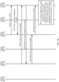
- FIG. 5A and FIG. 5B are a schematic flowchart of a method for providing a PaaS service according to an embodiment of this application.
- a scenario shown in FIG. 5A and FIG. 5B is a scenario in which a real tenant applies for a PaaS instance for the first time.
- the scenario in which a real tenant applies for a PaaS instance for the first time may include the following procedure.
- the cloud computing service page sends an HTTP message to a PaaS management system, for example, to a PaaS tenant service component 210.
- the PaaS tenant service component 210 initiates an invocation of virtual tenant selection, namely, "select a virtual tenant()", to a virtual tenant resource pool component 220.
- the virtual tenant resource pool component 220 allocates an unoccupied virtual tenant to the real tenant from an internal resource pool of the virtual tenant resource pool component 220, and records a correspondence between the real tenant and the virtual tenant.
- the virtual tenant resource pool component 220 returns information about the virtual tenant to the PaaS tenant service component 210.
- the PaaS tenant service component 210 transfers the information about the virtual tenant to a PaaS tenant proxy component 230, and also initiates an invocation of VM creation, namely, "create a VM()".
- the PaaS tenant proxy component 230 After receiving the invocation of VM creation, the PaaS tenant proxy component 230 sends an HTTP message to an IAM component, to obtain an identity authentication token of the virtual tenant.
- the IAM component returns the identity authentication token of the virtual tenant to the PaaS tenant proxy component 230.
- the PaaS tenant proxy component 230 After obtaining the identity authentication token, the PaaS tenant proxy component 230 initiates an HTTP message for creating a VM (that is, creating a PaaS instance) to an IaaS management system 300.
- the IaaS management system 300 After successfully creating a VM, the IaaS management system 300 returns an acknowledgement message to the PaaS tenant proxy component 230.
- the PaaS tenant service component 210 initiates an HTTP message for creating a data network adapter to the IaaS management system 300, to instruct the IaaS management system 300 to create a data network adapter that is configured to communicate with a first infrastructure resource group.
- the IaaS management system 300 After creating the data network adapter, the IaaS management system 300 returns an acknowledgement message to the PaaS tenant proxy component 230.
- the PaaS tenant service component 210 initiates a data network adapter mounting message to the PaaS tenant proxy component 230.
- the PaaS tenant proxy component 230 After receiving the data network adapter mounting message, the PaaS tenant proxy component 230 initiates an HTTP message that instructs to mount the data network adapter onto the VM to the IaaS management system 300.
- the IaaS management system 300 queries, from the IAM component, whether the virtual tenant is authorized, and when the virtual tenant is authorized, the IaaS management system 300 can perform the operation of mounting the data network adapter to the VM.
- the PaaS management system can allow the data network adapter of the real tenant to be mounted onto the virtual tenant, so that a resource of a VM of a PaaS is connected to a network of the real tenant by using the data network adapter of the real tenant.
- FIG. 6 is a schematic flowchart of a method 700 for providing a PaaS service according to an embodiment of this application.
- a scenario shown in FIG. 6 is a scenario in which a real tenant changes a PaaS instance. That the PaaS management system receives a PaaS operation request sent by a first real tenant in S510 may include: receiving, by the PaaS management system, a PaaS operation request that instructs to change a PaaS instance and that is sent by the first real tenant.
- That the PaaS management system controls, based on the PaaS operation request and the information about the first virtual tenant by using the first virtual tenant, an infrastructure as a service IaaS management system to process an IaaS operation corresponding to the PaaS operation in S530 may include: determining, by the PaaS management system based on the PaaS operation request, that the IaaS operation corresponding to the PaaS operation is changing a parameter of the PaaS instance; and controlling, by the PaaS management system by using the first virtual tenant, the IaaS management system to change the parameter of the PaaS instance.
- the scenario in which a real tenant changes a PaaS instance may include the following procedure.
- the cloud computing service page sends an HTTP message to a PaaS management system, specifically, to a PaaS tenant service component 210.
- the PaaS tenant service component 210 initiates an invocation of virtual tenant determining, namely, "determine a virtual tenant()", to a virtual tenant resource pool component 220.
- the virtual tenant resource pool component 220 determines, based on recorded correspondences between real tenants and virtual tenants, a virtual tenant corresponding to the real tenant.
- the virtual tenant resource pool component 220 returns information about the virtual tenant to the PaaS tenant service component 210.
- the PaaS tenant service component 210 transfers the information about the virtual tenant to a PaaS tenant proxy component 230, and also initiates an invocation of VM changing, namely, "change a VM()".
- the PaaS tenant proxy component 230 After receiving the invocation of VM changing, the PaaS tenant proxy component 230 sends an HTTP message to an IAM component, to obtain an identity authentication token of the virtual tenant.
- the PaaS tenant proxy component 230 obtains the identity authentication token.
- the PaaS tenant proxy component 230 After obtaining the identity authentication token, the PaaS tenant proxy component 230 initiates an HTTP message for changing a VM to an IaaS management system 300.
- the IaaS management system 300 After receiving the HTTP message for changing a VM, the IaaS management system 300 changes a parameter of a virtual machine.
- a PaaS management system 800 may include a processor 810, a network interface 820, and a memory 830.
- the memory 830 may be configured to store an instruction executed by the processor 810, and the like.
- the processor 810 and the network interface 820 are configured to execute the instruction stored in the memory 830.
- the PaaS management system 800 is configured to perform the method for providing a PaaS service in the embodiments of this application.
- Components in the PaaS management system 800 may communicate with each other by using an internal connection channel, to transfer a control signal and/or a data signal.
- the processor may be an integrated circuit chip and has a signal processing capability.
- steps in the foregoing method embodiments can be implemented by using an integrated logic circuit of hardware in the processor, or by using instructions in a form of software.
- the processor may be a general-purpose processor, a Digital Signal Processor ( DSP), an Application-Specific Integrated Circuit(ASIC), a Field Programmable Gate Array(FPGA) or another programmable logic device, a discrete gate or transistor logic device, or a discrete hardware component.
- DSP Digital Signal Processor
- ASIC Application-Specific Integrated Circuit
- FPGA Field Programmable Gate Array
- the processor may implement or perform the methods, the steps, and logical block diagrams that are disclosed in the embodiments of this application.
- the general-purpose processor may be a microprocessor or the processor may be any conventional processor, or the like. Steps of the methods disclosed with reference to the embodiments of this application may be directly executed and accomplished by a hardware decoding processor, or may be executed and accomplished by using a combination of hardware and software modules in a decoding processor.
- the software module may be located in a mature storage medium in the art, such as a random access memory, a flash memory, a read-only memory, a programmable read-only memory, an electrically erasable programmable memory, or a register.
- the storage medium is located in the memory, and the processor reads information in the memory and completes the steps in the foregoing methods in combination with hardware of the processor.
- the memory in the embodiments of this application may be a volatile memory or a nonvolatile memory, or may include a volatile memory and a nonvolatile memory.
- the nonvolatile memory may be a Read-Only Memory, (ROM), a Programmable ROM(PROM), an erasable programmable read-only memory (EPROM), an electrically erasable programmable read-only memory (Electrically EPROM, EEPROM), or a flash memory.
- the volatile memory may be Random Access Memory (RAM), used as an external cache.
- RAMs may be used, for example, a static random access memory (Static RAM, SRAM), a dynamic random access memory (Dynamic RAM, DRAM), a synchronous dynamic random access memory (Synchronous DRAM, SDRAM), a double data rate synchronous dynamic random access memory (Double Data Rate SDRAM, DDR SDRAM), an enhanced synchronous dynamic random access memory (Enhanced SDRAM, ESDRAM), a synchronous link dynamic random access memory (Synchlink DRAM, SLDRAM), and a direct rambus random access memory (Direct Rambus RAM, DR RAM).
- Static RAM static random access memory
- DRAM dynamic random access memory
- DRAM synchronous dynamic random access memory
- SDRAM synchronous dynamic random access memory
- DDR SDRAM double data rate synchronous dynamic random access memory
- Enhanced SDRAM, ESDRAM enhanced synchronous dynamic random access memory
- Synchrobus RAM synchronous link dynamic random access memory
- Direct Rambus RAM Direct Rambus RAM
- the network interface is configured to receive a PaaS operation request sent by a first real tenant.
- the network interface 820 may be one network interface, or may be a plurality of network interfaces.
- the network interface may be a wired interface, for example, a Fiber Distributed Data Interface(FDDI) or a Gigabit Ethernet (GE) interface; or the network interface may be a wireless interface.
- FDDI Fiber Distributed Data Interface
- GE Gigabit Ethernet
- a person of ordinary skill in the art may be aware that, in combination with the examples described in the embodiments disclosed in this specification, units and algorithm steps may be implemented by electronic hardware or a combination of computer software and electronic hardware. Whether the functions are performed by hardware or software depends on particular applications and design constraint conditions of the technical solutions. A person skilled in the art may use different methods to implement the described functions for each particular application, but it should not be considered that the implementation goes beyond the scope of this application.
- the disclosed system, apparatus, and method may be implemented in other manners.
- the described apparatus embodiment is merely an example.
- the unit division is merely logical function division and may be other division in actual implementation.
- a plurality of units or components may be combined or integrated into another system, or some features may be ignored or not performed.
- the displayed or discussed mutual couplings or direct couplings or communication connections may be implemented by using some interfaces.
- the indirect couplings or communication connections between the apparatuses or units may be implemented in electronic, mechanical, or other forms.
- the units described as separate parts may or may not be physically separate, and parts displayed as units may or may not be physical units, may be located in one position, or may be distributed on a plurality of network units. Some or all of the units may be selected based on actual requirements to achieve the objectives of the solutions of the embodiments.
- the functions When the functions are implemented in a form of a software functional unit and sold or used as an independent product, the functions may be stored in a computer-readable storage medium. Based on such an understanding, the technical solutions of this application essentially, or the part contributing to the prior art, or some of the technical solutions may be implemented in a form of a software product.
- the software product is stored in a storage medium, and includes several instructions for instructing a computer device (which may be a personal computer, a server, a network device, or the like) to perform all or some of the steps of the methods described in the embodiments of this application.
Landscapes
- Engineering & Computer Science (AREA)
- Software Systems (AREA)
- Computer Networks & Wireless Communication (AREA)
- Signal Processing (AREA)
- Theoretical Computer Science (AREA)
- General Engineering & Computer Science (AREA)
- Physics & Mathematics (AREA)
- General Physics & Mathematics (AREA)
- Computer Hardware Design (AREA)
- Computer Security & Cryptography (AREA)
- Computing Systems (AREA)
- Stored Programmes (AREA)
Description
- This application relates to the field of cloud computing services, and more specifically, to a method for providing a platform as a service (PaaS) service, and a platform as a service PaaS management system.
- In cloud computing services, services provided by a cloud computing service architecture for a user usually include an infrastructure as a service (IaaS) service, a platform as a service (PaaS) service, a software as a service (SaaS) service, and the like.
When a user leases both the PaaS service and the IaaS service in the cloud computing service architecture, resource management performed by the IaaS service and resource management performed by the PaaS service conflict with each other in an existing management system. The IaaS service manages an infrastructure resource of the user, for example, at least one of infrastructure resources such as a central processing unit (Central Processing Unit, CPU), a memory, a storage medium, a network, and a router (router), and the infrastructure resource of the user includes an infrastructure resource of a software service provided for running the PaaS service. In addition, the PaaS service is based on the IaaS service, and the PaaS service deploys a common software service on an infrastructure resource provided by the IaaS service. Therefore, both the PaaS service and the IaaS service can manage infrastructure resources together, and consequently a conflict occurs between management performed by the PaaS service and management performed by the IaaS service.
For example, the infrastructure resource of the software service provided for running the PaaS service can be deleted on a service page of the IaaS service. For another example, a network policy of the IaaS service may affect internal communication of the PaaS service.US2016043968A1 discloses that a resource management system can receive a request for a service. A request may indicate preferences for allocation resources (e.g., a resource definition) to enable the service. A resource definition may indicate a topology of the computing resources to allocate for the user. The topology may indicate what computing resources to allocate and how to allocate those computing resource. Based on the information indicated by a request, the resource management system may determine a placement policy for allocation of computing resources indicated by the request. A placement policy may indicate a placement of one or more computing resources requested by a user. The placement policy may indicate where and how computing resources are to be placed once allocated. The computing resources may be allocated based on the placement policy and the resource definition. - The present invention is set out in the appended set of claims. This application provides a method for providing a PaaS service and a platform as a service PaaS management system, so that not only a multi-tenant requirement is met, but also a conflict problem existing between infrastructure resource management performed by an IaaS service and infrastructure resource management performed by a PaaS service can be resolved.
-
-
FIG. 1 is a schematic block diagram of a PaaS management system according to an embodiment of this application; -
FIG. 2 is a schematic framework of a multi-tenant component that is applied to a PaaS management system according to an embodiment of this application; -
FIG. 3 is a schematic block diagram of a cloud computing service architecture according to an embodiment of this application; -
FIG. 4 is a schematic flowchart of a method for providing a PaaS service according to an embodiment of this application; -
FIG. 5A andFIG. 5B are a schematic flowchart of a method for providing a PaaS service according to another embodiment of this application; -
FIG. 6 is a schematic flowchart of a method for providing a PaaS service according to another embodiment of this application; and -
FIG. 7 is a schematic block diagram of a PaaS management system according to another embodiment of this application. - The following describes the technical solutions in this application with reference to the accompanying drawings.
- In cloud computing services, services provided by a cloud computing service architecture for a user usually include an Infrastructure as a Service ( IaaS) service, a Platform as a Service ( PaaS) service, a Software as a Service (SaaS) service, and the like.
- The IaaS service provides, in a form of a service, the user with permission to use at least one of infrastructure resources such as a CPU, a memory, a storage medium, a network, and a router. The user does not need to care about or manage any specific hardware resource, and the service saves a place and manpower and reduces maintenance costs. In addition, the IaaS service provides pay-as-you-grow convenience and subscribe-and-use convenience for the user, significantly improving flexibility of managing information technology (Information Technology, IT) infrastructure resources by the user.
- The PaaS service provides the user with an IaaS service-based software platform in a form of a service. The PaaS service invokes a hardware resource by using an Application Programming Interface (API) provided by the IaaS service. The hardware resource integrates with a common software business capability, to provide the user with complete infrastructure resource application services, for example, a database service, a messaging service, and a cache service. With the PaaS service, the user can focus more on a software service on an application software platform, without paying attention to application, expansion, and maintenance of infrastructure resources.
- The SaaS service is a mode in which a software service is provided by using the Internet. A vendor deploys all software on a server of the vendor. The user may subscribe to a required software service from the vendor based on an actual requirement of the user by using the Internet.
- A multi-tenancy technology, or referred to as a multi-leasing technology, is a software architecture technology. The multi-tenancy technology explores and implements how to share a same system or program component in a multi-tenant environment while still ensuring data isolation between tenants.
- The multi-tenancy technology is widely used in the SaaS service and the IaaS service, and becomes a key technology of the SaaS service. In consensus of the industry, the multi-tenancy technology is generally divided into different categories by isolation degree: a hardware virtualization multi-tenancy technology, a database isolation multi-tenancy technology, a database sharing multi-tenancy technology, and the like. With reference to classification of an IT consulting company Gartner (Gartner), more detailed classification may be performed for the multi-tenancy technology. For example, the multi-tenancy technology may be further divided into categories such as a hardware sharing multi-tenancy technology, an operating system (Operating System, OS) sharing multi-tenancy technology, a database sharing multi-tenancy technology, and an everything sharing multi-tenancy technology.
- In the industry, a hardware sharing method is selected to implement the multi-tenancy technology for most IaaS services for the following reasons: First, a hardware virtualization technology is mature and of moderate difficulty, and second, hardware virtualization accords with an idea of the IaaS service. The SaaS service has an obvious commonality in user requirements because businesses of the SaaS service are highly consistent, in other words, the provided businesses are oriented to a specific field. Most of companies with a profound data sharing capability, for example, Google, select the everything sharing multi-tenancy technology.
- When the user leases both the PaaS service and the IaaS service in the cloud computing service architecture, resource management performed by the IaaS service and resource management performed by the PaaS service conflict with each other in an existing management system. The IaaS service manages an infrastructure resource of the user, for example, at least one of infrastructure resources such as a CPU, a memory, a storage medium, a network, and a router, and the infrastructure resource of the user includes an infrastructure resource of a software service provided for running the PaaS service. In addition, the PaaS service is based on the IaaS service, and the PaaS service deploys a common software service on an infrastructure resource provided by the IaaS service. Therefore, both the PaaS service and the IaaS service can manage infrastructure resources together, and consequently a conflict occurs between management performed by the PaaS service and management performed by the IaaS service. For example, the infrastructure resource of the software service provided for running the PaaS service can be deleted on a service page of the IaaS service. For another example, a network policy of the IaaS service may affect internal communication of the PaaS service.
- In addition, to reduce management work of the user, the PaaS service provides the user only with a service address and a port. However, in an existing solution, when a user leases both the PaaS service and the IaaS service, for the user, an infrastructure resource corresponding to the PaaS service is exposed to the user in an IaaS management system. As a result, the user needs to care about resulting problems, for example, port security and a firewall access rule. These resulting tasks are not originally required by the user, and also bring a security risk to the user.
- To resolve the foregoing problem, this application provides, on the basis of a hardware sharing IaaS, an improved PaaS management system that can meet a multi-tenant requirement.
FIG. 1 is a schematic block diagram of aPaaS management system 100 according to an embodiment of this application. ThePaaS management system 100 may include: - a
receiving module 110, configured to receive a PaaS operation request sent by a first real tenant, where the PaaS operation request is used to indicate a PaaS operation intended for a PaaS resource; and - a
processing module 120, configured to determine information about a first virtual tenant corresponding to the first real tenant, where there are one-to-one correspondences between real tenants and virtual tenants, and the first real tenant and the first virtual tenant are a pair in the one-to-one correspondences; and - the
processing module 120 is further configured to control, based on the PaaS operation request and the information about the first virtual tenant by using the first virtual tenant, an IaaS management system to process an IaaS operation corresponding to the PaaS operation. - A cloud computing service architecture may provide a PaaS service for the first real tenant by using the
PaaS management system 100 in this embodiment of this application. The cloud computing service architecture may provide an IaaS service for the first real tenant by using the IaaS management system. - The receiving
module 110 in thePaaS management system 100 may specifically include a PaaS tenant service component that is configured to interact with a real tenant. Theprocessing module 120 may specifically include some functions of the PaaS tenant service component, a virtual tenant resource pool component that manages the one-to-one correspondences between real tenants and virtual tenants, and a PaaS tenant proxy component that is used as a proxy for the real tenant to perform an IaaS operation. - The following provides a detailed description with reference to
FIG. 2. FIG. 2 is a schematic block diagram of an applicationPaaS management system 200 according to an embodiment of this application. As shown inFIG. 2 , thePaaS management system 200 is a management system of a cloud computing service architecture at a platform (Platform, P) layer. In other words, the PaaS management system is a management system configured to process a PaaS operation in the cloud computing service architecture. AnIaaS management system 300 is a management system of the cloud computing service architecture at an infrastructure (Infrastructure, I) layer. In other words, the IaaS management system is a management system configured to process an IaaS operation in the cloud computing service architecture. For a tenant, for example, a first real tenant, the cloud computing service architecture provides a PaaS service for the first real tenant by using thePaaS management system 200. In addition, the cloud computing service architecture may also provide an IaaS service for the first real tenant by using theIaaS management system 300. However, this is not limited in this embodiment of this application. - The
PaaS management system 200 shown inFIG. 2 includes a PaaStenant service component 210, a virtual tenantresource pool component 220, and a PaaStenant proxy component 230. - The PaaS
tenant service component 210 is configured to receive a PaaS operation request sent by the first real tenant to thePaaS management system 200. The PaaS operation request is used to indicate a PaaS operation intended for a PaaS resource. Herein the PaaS resource is an infrastructure resource and a software resource on the infrastructure resource. Specifically, the PaaStenant service component 210 is configured to interact with a real tenant and respond to a PaaS operation request from the real tenant. The PaaStenant service component 210 may be an application deployed in a web (web) container of the infrastructure resource, and provide an interface for a cloud computing service page in an HTTP form. The real tenant may send the PaaS operation request to the PaaStenant service component 210 by using the cloud computing service page. The PaaStenant service component 210 responds to the PaaS operation request and processes a related PaaS operation, for example, applying for a PaaS instance, restarting a PaaS instance, changing a PaaS instance, or deleting a PaaS instance. - The PaaS
tenant service component 210 is further configured to interact with the virtual tenantresource pool component 220 and the PaaStenant proxy component 230, to perform the PaaS operation for the real tenant. The PaaStenant service component 210 requests a first virtual tenant corresponding to the first real tenant from the virtual tenantresource pool component 220. The PaaStenant service component 210 further performs corresponding processing, and separates an IaaS operation corresponding to the PaaS operation indicated by the PaaS operation request, so that the PaaStenant proxy component 230 performs the IaaS operation subsequently. - It should be understood that, as shown in
FIG. 2 , the PaaStenant service component 210 may perform logic such as necessary authentication and a necessary security check by using an identity and access management (IAM) component. - The virtual tenant
resource pool component 220 is configured to manage one-to-one correspondences between real tenants and virtual tenants. The first real tenant and the first virtual tenant are a pair in the one-to-one correspondences. The virtual tenantresource pool component 220 is further configured to send information about the first virtual tenant to the PaaStenant service component 210. - Specifically, the virtual tenant
resource pool component 220 may also be a built-in component, and interacts with the PaaStenant service component 210 in a form of a program interface. Both the virtual tenantresource pool component 220 and the PaaStenant service component 210 are deployed in a same application of a same web container. In an embodiment of this application, the cloud computing service architecture may preset a plurality of virtual tenants to form a resource pool that is stored in the virtual tenantresource pool component 220 for use. For a real tenant who leases both the IaaS service and the PaaS service, when the real tenant applies for a PaaS instance for the first time, the PaaStenant service component 210 initiates an invocation of virtual tenant selection to the virtual tenantresource pool component 220. In this case, the virtual tenantresource pool component 220 allocates an unoccupied virtual tenant to the real tenant from an internal resource pool, records a correspondence between the real tenant and the virtual tenant, and returns information about the virtual tenant to the PaaStenant service component 210. - After allocating a virtual tenant to each real tenant, the virtual tenant
resource pool component 220 records correspondences between real tenants and virtual tenants one by one. In a subsequent PaaS operation request process (for example, when a real tenant re-applies for, changes, or deletes a PaaS instance), the virtual tenantresource pool component 220 directly returns information about a corresponding virtual tenant to the PaaStenant service component 210. - It should be understood that the real tenant in the embodiments of this application is a tenant who leases the PaaS service and who can initiate a PaaS operation request by using the PaaS management system. However, the real tenant does not have permission to manage an infrastructure resource finally corresponding to the PaaS operation request. In other words, the real tenant does not have permission to manage, by using the IaaS management system, the infrastructure resource corresponding to the PaaS operation request. Alternatively, the real tenant may be a tenant who leases the IaaS service and who can initiate an IaaS operation request by using the IaaS management system. The real tenant has permission to manage an infrastructure resource corresponding to the IaaS operation request initiated by the real tenant by using the IaaS management system. For example, the real tenant is registered by a user in the PaaS management system. The user may set a user name and a password for identity authentication performed by the PaaS management system, so that the user can log in to the PaaS management system to use the PaaS service. The virtual tenant is not a tenant who actually exists, but a tenant that is allocated to the real tenant by the PaaS management system, that is used as a proxy for the real tenant, and that has permission to manage the infrastructure resource corresponding to the PaaS operation request. In other words, the virtual tenant has permission to manage, by using the IaaS management system, the infrastructure resource corresponding to the PaaS operation request. For example, the virtual tenant is an ID or a number allocated by the PaaS management system to a registered real tenant. However, the virtual tenant does not have permission to manage the infrastructure resource corresponding to the IaaS operation request initiated by the real tenant by using the IaaS management system. For the IaaS management system, the real tenant and the virtual tenant are two different tenants, and the IaaS management system isolates management permission of the real tenant from that of the virtual tenant.
- The PaaS
tenant proxy component 230 is configured to receive the information about the first virtual tenant and related information of the IaaS operation corresponding to the PaaS operation that are sent by the PaaStenant service component 210, work as a proxy for the first real tenant by using the first virtual tenant, and control theIaaS management system 300 to process the IaaS operation corresponding to the PaaS operation. - Specifically, the PaaS
tenant proxy component 230 mainly performs identity proxy work for the real tenant, and controls, with a proxy identity of the real tenant, theIaaS management system 300 to manage a corresponding infrastructure resource. - After selecting or retrieving the first virtual tenant corresponding to the first real tenant, the virtual tenant
resource pool component 220 sends the information about the first virtual tenant to the PaaStenant service component 210. The PaaStenant service component 210 sends the information about the first virtual tenant and the related information of the IaaS operation corresponding to the PaaS operation to the PaaStenant proxy component 230. The PaaStenant proxy component 230 works as the proxy for the first real tenant by using the first virtual tenant, and controls theIaaS management system 300 to process the IaaS operation corresponding to the PaaS operation, for example, create a Virtual Machine (VM) (that is, create a PaaS instance), change a VM resource, or delete a VM resource. - Optionally, in this embodiment of this application, the PaaS
tenant proxy component 230 may perform authentication on the first virtual tenant by using the IAM component, to obtain an identity authentication token of the first virtual tenant. The PaaStenant proxy component 230 works as the proxy for the first real tenant by using the identity authentication token of the first virtual tenant, to initiate a corresponding IaaS operation instruction to theIaaS management system 300. - It should be understood that, in this embodiment of this application, the cloud computing service architecture provides the IaaS service for the first real tenant based on a first infrastructure resource group; only the first real tenant has permission to manage an infrastructure resource in the first infrastructure resource group; the cloud computing service architecture provides the PaaS service for the first real tenant based on a second infrastructure resource group; and only the first virtual tenant has permission to manage an infrastructure resource in the second infrastructure resource group.
- According to the PaaS management system in this embodiment of this application, one corresponding virtual tenant is introduced for each real tenant in the PaaS management system, so that the PaaS management system manages an infrastructure resource by using the virtual tenant. The first real tenant and the first virtual tenant are a pair in a plurality of one-to-one correspondences. Therefore, PaaS service management corresponding to the first real tenant and management of another tenant are isolated from each other. In this way, management of a plurality of tenants is isolated from each other, and a conflict problem existing between infrastructure resource management performed by the IaaS service and infrastructure resource management performed by the PaaS service can be further resolved.
- For the IaaS management system, the real tenant and the virtual tenant are two different tenants, the real tenant has only the permission to manage the infrastructure resource corresponding to the IaaS operation request initiated by the real tenant by using the IaaS management system, the virtual tenant has only the permission to manage the infrastructure resource corresponding to the PaaS operation request initiated by the real tenant by using the PaaS management system, and the IaaS management system isolates the management permission of the real tenant from that of the virtual tenant. In this way, not only the management conflict problem can be resolved, but also security of a cloud computing service can be improved. The PaaS management system introduces one corresponding virtual tenant for each real tenant. This can ensure mutual resource isolation between a plurality of tenants. In conclusion, according to the PaaS management system in this embodiment of the present invention, not only a multi-tenant requirement is met, but also network isolation between infrastructure resources respectively corresponding to the IaaS service and the PaaS service can be performed, thereby resolving the conflict problem existing between infrastructure resource management performed by the IaaS service and infrastructure resource management performed by the PaaS service, and improving the security of the entire cloud computing service.
- An embodiment of this application further provides a cloud computing service architecture.
FIG. 3 is a schematic block diagram of a cloudcomputing service architecture 400 according to this embodiment of this application. The cloudcomputing service architecture 400 provides an infrastructure as a service IaaS service and a platform as a service PaaS service for a first real tenant. The cloudcomputing service architecture 400 includes a first infrastructure resource group 410 and a secondinfrastructure resource group 420. The cloudcomputing service architecture 400 provides the IaaS service for the first real tenant based on the first infrastructure resource group 410. Only the first real tenant has permission to manage an infrastructure resource in the first infrastructure resource group 410. The cloudcomputing service architecture 400 provides the PaaS service for the first real tenant based on the secondinfrastructure resource group 420. Only a first virtual tenant has permission to manage an infrastructure resource in the secondinfrastructure resource group 420. There are one-to-one correspondences between real tenants and virtual tenants, and the first real tenant and the first virtual tenant are a pair in the one-to-one correspondences. - Specifically, a PaaS management system of the cloud
computing service architecture 400 generates a corresponding virtual tenant for each real tenant who accepts the PaaS service. When the first real tenant applies for a PaaS instance, the PaaS management system manages, by using an identity of the first virtual tenant, the secondinfrastructure resource group 420 corresponding to the PaaS instance. For example, an infrastructure resource corresponding to the PaaS instance, such as a VM, a storage medium, a network, or a router, falls within a range of management permission of the first virtual tenant. All operations on the infrastructure resource of the PaaS instance of the first real tenant, that is, all operations on the secondinfrastructure resource group 420 managed by the first virtual tenant (for example, releasing the PaaS instance, changing the PaaS instance, restarting the PaaS instance, or increasing a disk) can be performed only by using the identity of the first virtual tenant corresponding to the first real tenant. In addition, this correspondence can be stored only in a background of the PaaS management system. In other words, the cloudcomputing service architecture 400 provides the PaaS service for the first real tenant based on the secondinfrastructure resource group 420, and only the first virtual tenant has the permission to manage the infrastructure resource in the secondinfrastructure resource group 420. An infrastructure resource created by the PaaS management system belongs to a virtual tenant, only the virtual tenant has permission to manage the infrastructure resource, and a real tenant cannot manage the infrastructure resource by using an IaaS management system. - For a case in which the cloud
computing service architecture 400 further provides the IaaS service for the first real tenant based on the first infrastructure resource group 410, only the first real tenant has the permission to manage the infrastructure resource in the first infrastructure resource group 410. An infrastructure resource that provides the IaaS service for a real tenant belongs to the real tenant, only the real tenant has permission to manage the infrastructure resource, and a virtual tenant cannot manage the infrastructure resource by using the PaaS management system. Herein the first infrastructure resource group 410 and the secondinfrastructure resource group 420 do not have a same infrastructure resource. - It should be understood that, for a real tenant, in some cases, data communication needs to be performed between infrastructure resources respectively corresponding to the IaaS service and the PaaS service that are leased by the real tenant. The second
infrastructure resource group 420 may include a PaaS instance, the PaaS instance includes a data network adapter, and the data network adapter is configured to perform data communication between the PaaS instance and the first infrastructure resource group 410. - In the cloud computing service architecture in this embodiment of this application, for a real tenant who leases both the IaaS service and the PaaS service, infrastructure resources respectively corresponding to the IaaS service and the PaaS service are classified into two parts: At least one of infrastructure resources such as a VM, a network, a CPU, a memory, a storage medium, and a router in the second
infrastructure resource group 420 corresponding to the PaaS service is managed by a virtual tenant by using the IaaS management system, under control of the real tenant by using the PaaS management system, for example, a PaaS management domain shown inFIG. 3 ; and at least one of infrastructure resources such as a VM, a network, a CPU, a memory, a storage medium, and a router in the first infrastructure resource group 410 corresponding to the IaaS service is managed by the real tenant by using the IaaS management system, for example, an IaaS management domain shown inFIG. 3 . The real tenant may control application, destruction, and the like of a resource of a PaaS instance by using the PaaS management system. In a network of the real tenant, only a network address and a port of the PaaS instance can be seen, and an infrastructure resource corresponding to the PaaS instance cannot be seen. The infrastructure resource corresponding to the PaaS instance can be managed only by using the virtual tenant. - A multi-network-adapter design may be used for the PaaS instance, so that a management network and a data network are independent of each other. Specifically, in a PaaS instance creation process, a plurality of network adapters may be created on a VM, and a management network adapter and a data network adapter are independent of each other, and belong to the management network and the data network, respectively. Communication in the management network is management communication, and includes internal communication of the PaaS service and control communication of the background of the PaaS management system. Communication in the data network is data communication, is external communication of the PaaS service, and is used to transmit data generated or required in a process in which a user uses the PaaS instance. The PaaS instance (that is, a virtual machine) provided by the cloud computing service architecture for the first real tenant includes a management network adapter. The management network adapter is configured to perform management communication between infrastructure resources in the second
infrastructure resource group 420. The management network adapter performs the internal communication of the PaaS service and the control communication of the background of the PaaS management system, and is independent of data communication of the real tenant. The management network is connected to a virtual network of the virtual tenant and is not interfered by the outside. The PaaS instance (that is, a virtual machine) provided by the cloud computing service architecture for the first real tenant includes a data network adapter. The data network adapter is configured to perform data communication between the PaaS instance and the first infrastructure resource group 410. The data network is connected to a virtual network of the real tenant, and can be managed only by the real tenant. - It should be understood that the cloud computing service architecture in this embodiment of this application is configured to provide a hardware or software service for a tenant. The cloud computing service architecture includes an infrastructure resource and software deployed on the infrastructure resource. For example, hardware of the cloud computing service architecture may include one or more of infrastructure resources such as a CPU, a memory, a storage medium, a network, and a router. The hardware of the cloud computing service architecture is connected to each other based on a physical device. Software of the cloud computing service architecture may include the PaaS management system, the IaaS management system, application software corresponding to the PaaS service leased by a tenant, and the like that are deployed on the foregoing hardware. The cloud computing service architecture may deploy the software on the hardware by using a virtualization technology. In this embodiment of this application, a specific form of the cloud computing service architecture is not limited.
- The real tenant has permission to manage the data network adapter of the PaaS instance. Capabilities of the real tenant such as a security group policy may take effect for the data network adapter. In this way, the real tenant may care about only the data network adapter, and does not need to care about another network adapter. This can simplify management work of the real tenant, and can also enhance a network isolation capability of the infrastructure resource corresponding to the PaaS service. In this embodiment of this application, different real tenants are corresponding to different virtual tenants, and networks of different virtual tenants are independent and mutually isolated networks. Therefore, for a plurality of tenants of the PaaS service, resources of the tenants are isolated from each other.
-
FIG. 4 is a schematic flowchart of amethod 500 for providing a PaaS service according to an embodiment of this application. Themethod 500 is based on a cloud computing service architecture. The cloud computing service architecture provides a PaaS service for a first real tenant by using a PaaS management system. Themethod 500 may include the following steps: - S510. The PaaS management system receives a PaaS operation request sent by a first real tenant, where the PaaS operation request is used to indicate a PaaS operation intended for a PaaS resource.
- S520. The PaaS management system determines information about a first virtual tenant corresponding to the first real tenant, where there are one-to-one correspondences between real tenants and virtual tenants, and the first real tenant and the first virtual tenant are a pair in the one-to-one correspondences.
- S530. The PaaS management system controls, based on the PaaS operation request and the information about the first virtual tenant by using the first virtual tenant, an IaaS management system of the cloud computing service architecture to process an IaaS operation corresponding to the PaaS operation.
- According to the method for providing a PaaS service in this embodiment of this application, one corresponding virtual tenant is introduced for each real tenant in the PaaS management system, so that the PaaS management system manages an infrastructure resource by using the virtual tenant. The first real tenant and the first virtual tenant are a pair in a plurality of one-to-one correspondences. Therefore, PaaS service management corresponding to the first real tenant and management of another tenant are isolated from each other. In this way, management of a plurality of tenants is isolated from each other, and a conflict problem existing between infrastructure resource management performed by an IaaS service and infrastructure resource management performed by a PaaS service can be further resolved.
- The following describes the method for providing a PaaS service in this embodiment of this application in detail by using two specific scenarios.
FIG. 5A andFIG. 5B are a schematic flowchart of a method 600 for providing a PaaS service according to an embodiment of this application. That the PaaS management system receives a PaaS operation request sent by a first real tenant in S510 may include: receiving, by the PaaS management system, a PaaS operation request that instructs to apply for a PaaS instance and that is sent by the first real tenant. That the PaaS management system controls, based on the PaaS operation request and the information about the first virtual tenant by using the first virtual tenant, an infrastructure as a service IaaS management system to process an IaaS operation corresponding to the PaaS operation in S530 may include: determining, by the PaaS management system based on the PaaS operation request, that the IaaS operation corresponding to the PaaS operation is creating the PaaS instance and creating a data network adapter; and controlling, by the PaaS management system by using the first virtual tenant, the IaaS management system to create the PaaS instance and create the data network adapter. -
FIG. 5A andFIG. 5B are a schematic flowchart of a method for providing a PaaS service according to an embodiment of this application. A scenario shown inFIG. 5A andFIG. 5B is a scenario in which a real tenant applies for a PaaS instance for the first time. As shown inFIG. 5A andFIG. 5B , the scenario in which a real tenant applies for a PaaS instance for the first time may include the following procedure. - S605. A real tenant clicks an "Apply for a PaaS instance" button on a cloud computing service page that may also be referred to as a PaaS console (console). The cloud computing service page sends an HTTP message to a PaaS management system, for example, to a PaaS
tenant service component 210. - S610. The PaaS
tenant service component 210 initiates an invocation of virtual tenant selection, namely, "select a virtual tenant()", to a virtual tenantresource pool component 220. - S615. The virtual tenant
resource pool component 220 allocates an unoccupied virtual tenant to the real tenant from an internal resource pool of the virtual tenantresource pool component 220, and records a correspondence between the real tenant and the virtual tenant. - S620. The virtual tenant
resource pool component 220 returns information about the virtual tenant to the PaaStenant service component 210. - S625. After receiving the information about the virtual tenant, the PaaS
tenant service component 210 transfers the information about the virtual tenant to a PaaStenant proxy component 230, and also initiates an invocation of VM creation, namely, "create a VM()". - S630. After receiving the invocation of VM creation, the PaaS
tenant proxy component 230 sends an HTTP message to an IAM component, to obtain an identity authentication token of the virtual tenant. - S635. The IAM component returns the identity authentication token of the virtual tenant to the PaaS
tenant proxy component 230. - S640. After obtaining the identity authentication token, the PaaS
tenant proxy component 230 initiates an HTTP message for creating a VM (that is, creating a PaaS instance) to anIaaS management system 300. - S645. After successfully creating a VM, the
IaaS management system 300 returns an acknowledgement message to the PaaStenant proxy component 230. - S650. After the VM is successfully created, the PaaS
tenant service component 210 initiates an HTTP message for creating a data network adapter to theIaaS management system 300, to instruct theIaaS management system 300 to create a data network adapter that is configured to communicate with a first infrastructure resource group. - S655. After creating the data network adapter, the
IaaS management system 300 returns an acknowledgement message to the PaaStenant proxy component 230. - S660. The PaaS
tenant service component 210 initiates a data network adapter mounting message to the PaaStenant proxy component 230. - S665. After receiving the data network adapter mounting message, the PaaS
tenant proxy component 230 initiates an HTTP message that instructs to mount the data network adapter onto the VM to theIaaS management system 300. - S670. For an operation of mounting the data network adapter onto the VM, the
IaaS management system 300 queries, from the IAM component, whether the virtual tenant is authorized, and when the virtual tenant is authorized, theIaaS management system 300 can perform the operation of mounting the data network adapter to the VM. - Only in this case, the PaaS management system can allow the data network adapter of the real tenant to be mounted onto the virtual tenant, so that a resource of a VM of a PaaS is connected to a network of the real tenant by using the data network adapter of the real tenant.
-
FIG. 6 is a schematic flowchart of a method 700 for providing a PaaS service according to an embodiment of this application. A scenario shown inFIG. 6 is a scenario in which a real tenant changes a PaaS instance. That the PaaS management system receives a PaaS operation request sent by a first real tenant in S510 may include: receiving, by the PaaS management system, a PaaS operation request that instructs to change a PaaS instance and that is sent by the first real tenant. That the PaaS management system controls, based on the PaaS operation request and the information about the first virtual tenant by using the first virtual tenant, an infrastructure as a service IaaS management system to process an IaaS operation corresponding to the PaaS operation in S530 may include: determining, by the PaaS management system based on the PaaS operation request, that the IaaS operation corresponding to the PaaS operation is changing a parameter of the PaaS instance; and controlling, by the PaaS management system by using the first virtual tenant, the IaaS management system to change the parameter of the PaaS instance. - As shown in
FIG. 6 , the scenario in which a real tenant changes a PaaS instance may include the following procedure. - S705. A real tenant clicks a "Change a PaaS instance" button on a cloud computing service page. The cloud computing service page sends an HTTP message to a PaaS management system, specifically, to a PaaS
tenant service component 210. - S710. The PaaS
tenant service component 210 initiates an invocation of virtual tenant determining, namely, "determine a virtual tenant()", to a virtual tenantresource pool component 220. - S715. The virtual tenant
resource pool component 220 determines, based on recorded correspondences between real tenants and virtual tenants, a virtual tenant corresponding to the real tenant. - S720. The virtual tenant
resource pool component 220 returns information about the virtual tenant to the PaaStenant service component 210. - S725. After receiving the information about the virtual tenant, the PaaS
tenant service component 210 transfers the information about the virtual tenant to a PaaStenant proxy component 230, and also initiates an invocation of VM changing, namely, "change a VM()". - S730. After receiving the invocation of VM changing, the PaaS
tenant proxy component 230 sends an HTTP message to an IAM component, to obtain an identity authentication token of the virtual tenant. - S735. The PaaS
tenant proxy component 230 obtains the identity authentication token. - S740. After obtaining the identity authentication token, the PaaS
tenant proxy component 230 initiates an HTTP message for changing a VM to anIaaS management system 300. - S745. After receiving the HTTP message for changing a VM, the
IaaS management system 300 changes a parameter of a virtual machine. - It should be noted that, in the embodiments of this application, the receiving
module 110 of the PaaS management system may be implemented by a network interface, and theprocessing module 120 may be implemented by a processor. As shown inFIG. 7 , aPaaS management system 800 may include aprocessor 810, a network interface 820, and amemory 830. Thememory 830 may be configured to store an instruction executed by theprocessor 810, and the like. Theprocessor 810 and the network interface 820 are configured to execute the instruction stored in thememory 830. When theprocessor 810 and the network interface 820 execute the instruction stored in thememory 830, thePaaS management system 800 is configured to perform the method for providing a PaaS service in the embodiments of this application. - Components in the
PaaS management system 800 may communicate with each other by using an internal connection channel, to transfer a control signal and/or a data signal. - It should be noted that the foregoing method embodiments of this application may be applied to a processor, or implemented by a processor. The processor may be an integrated circuit chip and has a signal processing capability. In an implementation process, steps in the foregoing method embodiments can be implemented by using an integrated logic circuit of hardware in the processor, or by using instructions in a form of software. The processor may be a general-purpose processor, a Digital Signal Processor ( DSP), an Application-Specific Integrated Circuit(ASIC), a Field Programmable Gate Array(FPGA) or another programmable logic device, a discrete gate or transistor logic device, or a discrete hardware component. The processor may implement or perform the methods, the steps, and logical block diagrams that are disclosed in the embodiments of this application. The general-purpose processor may be a microprocessor or the processor may be any conventional processor, or the like. Steps of the methods disclosed with reference to the embodiments of this application may be directly executed and accomplished by a hardware decoding processor, or may be executed and accomplished by using a combination of hardware and software modules in a decoding processor. The software module may be located in a mature storage medium in the art, such as a random access memory, a flash memory, a read-only memory, a programmable read-only memory, an electrically erasable programmable memory, or a register. The storage medium is located in the memory, and the processor reads information in the memory and completes the steps in the foregoing methods in combination with hardware of the processor.
- It may be understood that the memory in the embodiments of this application may be a volatile memory or a nonvolatile memory, or may include a volatile memory and a nonvolatile memory. The nonvolatile memory may be a Read-Only Memory, (ROM), a Programmable ROM(PROM), an erasable programmable read-only memory (EPROM), an electrically erasable programmable read-only memory (Electrically EPROM, EEPROM), or a flash memory. The volatile memory may be Random Access Memory (RAM), used as an external cache. As examples but not limitative descriptions, many forms of RAMs may be used, for example, a static random access memory (Static RAM, SRAM), a dynamic random access memory (Dynamic RAM, DRAM), a synchronous dynamic random access memory (Synchronous DRAM, SDRAM), a double data rate synchronous dynamic random access memory (Double Data Rate SDRAM, DDR SDRAM), an enhanced synchronous dynamic random access memory (Enhanced SDRAM, ESDRAM), a synchronous link dynamic random access memory (Synchlink DRAM, SLDRAM), and a direct rambus random access memory (Direct Rambus RAM, DR RAM). It should be noted that the memory of the systems and methods described in this specification includes but is not limited to these memories and any memory of another proper type.
- The network interface is configured to receive a PaaS operation request sent by a first real tenant. The network interface 820 may be one network interface, or may be a plurality of network interfaces. The network interface may be a wired interface, for example, a Fiber Distributed Data Interface(FDDI) or a Gigabit Ethernet (GE) interface; or the network interface may be a wireless interface. A person of ordinary skill in the art may be aware that, in combination with the examples described in the embodiments disclosed in this specification, units and algorithm steps may be implemented by electronic hardware or a combination of computer software and electronic hardware. Whether the functions are performed by hardware or software depends on particular applications and design constraint conditions of the technical solutions. A person skilled in the art may use different methods to implement the described functions for each particular application, but it should not be considered that the implementation goes beyond the scope of this application.
- It may be clearly understood by a person skilled in the art that, for the purpose of convenient and brief description, for a detailed working process of the foregoing system, apparatus, and unit, refer to a corresponding process in the foregoing method embodiments, and details are not described herein again.
- In the several embodiments provided in this application, it should be understood that the disclosed system, apparatus, and method may be implemented in other manners. For example, the described apparatus embodiment is merely an example. For example, the unit division is merely logical function division and may be other division in actual implementation. For example, a plurality of units or components may be combined or integrated into another system, or some features may be ignored or not performed. In addition, the displayed or discussed mutual couplings or direct couplings or communication connections may be implemented by using some interfaces. The indirect couplings or communication connections between the apparatuses or units may be implemented in electronic, mechanical, or other forms.
- The units described as separate parts may or may not be physically separate, and parts displayed as units may or may not be physical units, may be located in one position, or may be distributed on a plurality of network units. Some or all of the units may be selected based on actual requirements to achieve the objectives of the solutions of the embodiments.
- In addition, functional units in the embodiments of this application may be integrated into one processing unit, or each of the units may exist alone physically, or two or more units may be integrated into one unit.
- When the functions are implemented in a form of a software functional unit and sold or used as an independent product, the functions may be stored in a computer-readable storage medium. Based on such an understanding, the technical solutions of this application essentially, or the part contributing to the prior art, or some of the technical solutions may be implemented in a form of a software product. The software product is stored in a storage medium, and includes several instructions for instructing a computer device (which may be a personal computer, a server, a network device, or the like) to perform all or some of the steps of the methods described in the embodiments of this application.
- The foregoing descriptions are merely specific implementations of this application, but are not intended to limit the protection scope of this application. Any variation or replacement readily figured out by a person skilled in the art within the technical scope disclosed in this application shall fall within the protection scope of this application. The invention is defined by the appended claims.
Claims (12)
- A method for providing a platform as a service, PaaS, service, wherein the method comprises:receiving (510), by a PaaS management system, a PaaS operation request sent by a first real tenant, wherein the PaaS operation request is used to indicate a PaaS operation intended for a PaaS resource;determining (520), by the PaaS management system, information about a first virtual tenant corresponding to the first real tenant, wherein there are one-to-one correspondences between real tenants and virtual tenants, and the first real tenant and the first virtual tenant are a pair in the one-to-one correspondences; andcontrolling (530), by the PaaS management system, based on the PaaS operation request and the information about the first virtual tenant , an infrastructure as a service, IaaS, management system, by using the first virtual tenant, to process an IaaS operation corresponding to the PaaS operation; wherein the IaaS management system is a management system configured to process an IaaS operation in a cloud computing service architecture; the cloud computing service architecture provides an IaaS service for the first real tenant based on a first infrastructure resource group; only the first real tenant has permission to manage an infrastructure resource in the first infrastructure resource group; the PaaS management system is a management system configured to process a PaaS operation in the cloud computing service architecture; the cloud computing service architecture provides a PaaS service for the first real tenant based on a second infrastructure resource group; and only the first virtual tenant has permission to manage an infrastructure resource in the second infrastructure resource group.
- The method according to claim 1, wherein a PaaS instance provided by the cloud computing service architecture for the first real tenant comprises a management network adapter, and the method further comprises:
performing, by the PaaS management system, management communication between infrastructure resources in the second infrastructure resource group by using the management network adapter. - The method according to claim 2, wherein the PaaS instance provided by the cloud computing service architecture for the first real tenant comprises a data network adapter, and the method further comprises:
performing, by the PaaS management system, data communication between the PaaS instance and the first infrastructure resource group by using the data network adapter. - The method according to claim 3, wherein the receiving, by a PaaS management system, a PaaS operation request sent by a first real tenant comprises:receiving (S605), by the PaaS management system, a PaaS operation request that instructs to apply for the PaaS instance and that is sent by the first real tenant; andthe controlling, by the PaaS management system based on the PaaS operation request and the information about the first virtual tenant by using the first virtual tenant, an infrastructure as a service IaaS management system to process an IaaS operation corresponding to the PaaS operation comprises:determining, by the PaaS management system based on the PaaS operation request, that the IaaS operation corresponding to the PaaS operation is creating the PaaS instance and creating the data network adapter; andcontrolling, by the PaaS management system, the IaaS management system to create the PaaS instance and create the data network adapter, by using the first virtual tenant.
- The method according to claim 2 or 3, wherein the receiving, by a PaaS management system, a PaaS operation request sent by a first real tenant comprises:receiving (S705), by the PaaS management system, a PaaS operation request that instructs to change the PaaS instance and that is sent by the first real tenant; andthe controlling, by the PaaS management system, based on the PaaS operation request and the information about the first virtual tenant by using the first virtual tenant, an infrastructure as a service IaaS management system to process an IaaS operation corresponding to the PaaS operation comprises:determining, by the PaaS management system, based on the PaaS operation request, that the IaaS operation corresponding to the PaaS operation is changing a parameter of the PaaS instance; andcontrolling, by the PaaS management system, by using the first virtual tenant, the IaaS management system to change the parameter of the PaaS instance.
- A platform as a service PaaS management system, wherein the PaaS management system comprises:a receiving module (110), configured to receive a PaaS operation request sent by a first real tenant, wherein the PaaS operation request is used to indicate a PaaS operation intended for a PaaS resource; anda processing module (120), configured to determine information about a first virtual tenant corresponding to the first real tenant, wherein there are one-to-one correspondences between real tenants and virtual tenants, and the first real tenant and the first virtual tenant are a pair in the one-to-one correspondences; andthe processing module (120) is further configured to control, based on the PaaS operation request and the information about the first virtual tenant , an infrastructure as a service IaaS management system, by using the first virtual tenant, to process an IaaS operation corresponding to the PaaS operation; wherein the IaaS management system is a management system configured to process an IaaS operation in a cloud computing service architecture; the cloud computing service architecture provides an IaaS service for the first real tenant based on a first infrastructure resource group; only the first real tenant has permission to manage an infrastructure resource in the first infrastructure resource group; the PaaS management system is a management system configured to process a PaaS operation in the cloud computing service architecture; the cloud computing service architecture provides a PaaS service for the first real tenant based on a second infrastructure resource group; and only the first virtual tenant has permission to manage an infrastructure resource in the second infrastructure resource group.
- The PaaS management system according to claim 6, wherein a PaaS instance provided by the cloud computing service architecture for the first real tenant comprises a management network adapter, and the management network adapter is configured to perform management communication between infrastructure resources in the second infrastructure resource group.
- The PaaS management system according to claim 7, wherein the PaaS instance provided by the cloud computing service architecture for the first real tenant comprises a data network adapter, and the data network adapter is configured to perform data communication between the PaaS instance and the first infrastructure resource group.
- The PaaS management system according to claim 8, wherein the receiving module is specifically configured to:receive a PaaS operation request that instructs to apply for the PaaS instance and that is sent by the first real tenant; andthe processing module is specifically configured to:determine, based on the PaaS operation request, that the IaaS operation corresponding to the PaaS operation is creating the PaaS instance and creating the data network adapter; andcontrol, by using the first virtual tenant, the IaaS management system to create the PaaS instance and create the data network adapter.
- The PaaS management system according to claim 7 or 8, wherein the receiving module is specifically configured to:receive a PaaS operation request that instructs to change the PaaS instance and that is sent by the first real tenant; andthe processing module is specifically configured to:determine, based on the PaaS operation request, that the IaaS operation corresponding to the PaaS operation is changing a parameter of the PaaS instance; andcontrol, by using the first virtual tenant, the IaaS management system to change the parameter of the PaaS instance.
- A computer program product comprising computer program instructions that when executed by a processing apparatus cause the processing apparatus to perform the method according to any of the preceding claims 1 to 5.
- A computer storage medium, wherein the computer storage medium is configured to store a computer program, and the computer program comprises an instruction used to perform the method according to any one of claims 1 to 5.
Applications Claiming Priority (2)
| Application Number | Priority Date | Filing Date | Title |
|---|---|---|---|
| CN201710216079.5A CN108667886B (en) | 2017-04-01 | 2017-04-01 | Method for providing PaaS service, management system and cloud computing service architecture |
| PCT/CN2018/074278 WO2018177013A1 (en) | 2017-04-01 | 2018-01-26 | Method for providing paas service, management system, and cloud computing service architecture |
Publications (3)
| Publication Number | Publication Date |
|---|---|
| EP3591939A4 EP3591939A4 (en) | 2020-01-08 |
| EP3591939A1 EP3591939A1 (en) | 2020-01-08 |
| EP3591939B1 true EP3591939B1 (en) | 2023-08-02 |
Family
ID=63675193
Family Applications (1)
| Application Number | Title | Priority Date | Filing Date |
|---|---|---|---|
| EP18774532.8A Active EP3591939B1 (en) | 2017-04-01 | 2018-01-26 | Method for providing paas service and management system |
Country Status (4)
| Country | Link |
|---|---|
| US (1) | US11438242B2 (en) |
| EP (1) | EP3591939B1 (en) |
| CN (1) | CN108667886B (en) |
| WO (1) | WO2018177013A1 (en) |
Families Citing this family (13)
| Publication number | Priority date | Publication date | Assignee | Title |
|---|---|---|---|---|
| US10911558B1 (en) * | 2019-05-15 | 2021-02-02 | Pivotal Software, Inc. | On-demand network segmentation |
| US11082526B2 (en) * | 2019-08-19 | 2021-08-03 | International Business Machines Corporation | Optimizing large parameter passing in a service mesh |
| CN110535964B (en) * | 2019-09-03 | 2021-12-14 | 北京首都在线科技股份有限公司 | Data processing method and device based on Paas connector |
| CN110545205B (en) * | 2019-09-03 | 2021-11-30 | 北京首都在线科技股份有限公司 | Tenant data processing method and processing device based on Paas network |
| CN110708310B (en) * | 2019-09-30 | 2022-02-08 | 杭州数梦工场科技有限公司 | Tenant-level authority management method, device and equipment |
| CN112579999B (en) * | 2019-09-30 | 2024-08-23 | 北京国双科技有限公司 | Data processing method and device |
| CN111784076A (en) * | 2020-07-22 | 2020-10-16 | 济源国泰自动化信息技术有限公司 | Cloud metering system for industrial Internet and use method thereof |
| CN114827136A (en) * | 2021-01-13 | 2022-07-29 | 新智数字科技有限公司 | Edge cloud cooperation method and terminal equipment |
| CN112667216B (en) * | 2021-02-10 | 2023-07-14 | 开放智能机器(上海)有限公司 | An edge computing terminal software framework system and its operation method |
| CN115048260B (en) * | 2021-03-09 | 2025-09-12 | 中核武汉核电运行技术股份有限公司 | A cloud computing-based nuclear power plant PaaS platform resource quota monitoring method and system |
| CN113111327B (en) * | 2021-04-27 | 2024-02-13 | 北京赛博云睿智能科技有限公司 | Resource management method and device of PaaS-based service portal management system |
| CN115102827B (en) * | 2022-05-27 | 2024-01-09 | 燕山大学 | A universal Internet platform for real-time monitoring of digital products in small and medium-sized manufacturing industries |
| US20250240293A1 (en) * | 2024-01-19 | 2025-07-24 | Dell Products L.P. | Multi-tenant secrets manager |
Family Cites Families (47)
| Publication number | Priority date | Publication date | Assignee | Title |
|---|---|---|---|---|
| US20050192999A1 (en) * | 2003-11-21 | 2005-09-01 | Cook Scott J. | System and method of virtualizing physical locations |
| US9282097B2 (en) * | 2010-05-07 | 2016-03-08 | Citrix Systems, Inc. | Systems and methods for providing single sign on access to enterprise SAAS and cloud hosted applications |
| US8448171B2 (en) * | 2011-01-07 | 2013-05-21 | International Business Machines Corporation | Communications between virtual machines that have been migrated |
| US8949427B2 (en) * | 2011-02-25 | 2015-02-03 | International Business Machines Corporation | Administering medical digital images with intelligent analytic execution of workflows |
| US9704207B2 (en) * | 2011-02-25 | 2017-07-11 | International Business Machines Corporation | Administering medical digital images in a distributed medical digital image computing environment with medical image caching |
| US9836485B2 (en) * | 2011-02-25 | 2017-12-05 | International Business Machines Corporation | Auditing database access in a distributed medical computing environment |
| US20120221346A1 (en) * | 2011-02-25 | 2012-08-30 | International Business Machines Corporation | Administering Medical Digital Images In A Distributed Medical Digital Image Computing Environment |
| CN103167003A (en) * | 2011-12-16 | 2013-06-19 | 上海博腾信息科技有限公司 | Cloud computing application platform |
| JP5939791B2 (en) * | 2011-12-22 | 2016-06-22 | キヤノン株式会社 | Server apparatus, system, information processing method, and program |
| US20140007189A1 (en) * | 2012-06-28 | 2014-01-02 | International Business Machines Corporation | Secure access to shared storage resources |
| US10419524B2 (en) * | 2012-09-07 | 2019-09-17 | Oracle International Corporation | System and method for workflow orchestration for use with a cloud computing environment |
| US9501541B2 (en) * | 2012-09-07 | 2016-11-22 | Oracle International Corporation | Separation of pod provisioning and service provisioning |
| US8959195B1 (en) * | 2012-09-27 | 2015-02-17 | Emc Corporation | Cloud service level attestation |
| CA2894894C (en) * | 2012-12-11 | 2019-10-22 | Deutsche Telekom Ag | Computer-implemented method, system and computer program product for deploying an application on a computing resource |
| US9467395B2 (en) * | 2013-03-13 | 2016-10-11 | Vmware, Inc. | Cloud computing nodes for aggregating cloud computing resources from multiple sources |
| US10454999B2 (en) * | 2013-03-14 | 2019-10-22 | Red Hat, Inc. | Coordination of inter-operable infrastructure as a service (IAAS) and platform as a service (PAAS) |
| GB2528584A (en) * | 2013-05-15 | 2016-01-27 | Hitachi Ltd | Computer system, and resource management method |
| EP3028528A4 (en) | 2013-08-27 | 2017-05-03 | Huawei Technologies Co., Ltd. | System and method for mobile network function virtualization |
| US10476760B2 (en) * | 2013-10-30 | 2019-11-12 | Oracle International Corporation | System and method for placement logic in a cloud platform environment |
| US9544188B2 (en) * | 2013-10-30 | 2017-01-10 | Oracle International Corporation | System and method for webtier providers in a cloud platform environment |
| US9760358B2 (en) * | 2013-10-30 | 2017-09-12 | Oracle International Corporation | System and method for test to production support in a cloud platform environment |
| CN103544319B (en) * | 2013-11-06 | 2016-09-21 | 浪潮(北京)电子信息产业有限公司 | A kind of method of many tenants shared data bank and multi-tenant database i.e. service system |
| CN104683125A (en) * | 2013-11-27 | 2015-06-03 | 上海墨芋电子科技有限公司 | Network storage management and debugging system of cloud computing |
| CN103699428A (en) * | 2013-12-20 | 2014-04-02 | 华为技术有限公司 | Method and computer device for affinity binding of interrupts of virtual network interface card |
| US9503447B2 (en) * | 2014-01-30 | 2016-11-22 | Sap Se | Secure communication between processes in cloud |
| US9912609B2 (en) * | 2014-08-08 | 2018-03-06 | Oracle International Corporation | Placement policy-based allocation of computing resources |
| EP3234947B1 (en) * | 2014-12-15 | 2023-04-05 | Hewlett Packard Enterprise Development LP | Nonvolatile memory cross-bar array |
| CN105897805B (en) * | 2015-01-04 | 2019-12-27 | 伊姆西公司 | Method and device for cross-layer scheduling of resources of data center with multi-layer architecture |
| CN105893139B (en) * | 2015-01-04 | 2020-09-04 | 伊姆西Ip控股有限责任公司 | Method and device for providing storage service for tenant in cloud storage environment |
| US9775008B2 (en) * | 2015-01-14 | 2017-09-26 | Kodiak Networks, Inc. | System and method for elastic scaling in a push to talk (PTT) platform using user affinity groups |
| US9887961B2 (en) * | 2015-05-22 | 2018-02-06 | International Business Machines Corporation | Multi-tenant aware dynamic host configuration protocol (DHCP) mechanism for cloud networking |
| CN106294435A (en) * | 2015-05-27 | 2017-01-04 | 陈志高 | A kind of cloud Content Management System based on PaaS cloud platform |
| CN104883369A (en) * | 2015-05-29 | 2015-09-02 | 天津大学 | Cloud configuration safety assessment method |
| US10361995B2 (en) * | 2015-11-09 | 2019-07-23 | International Business Machines Corporation | Management of clustered and replicated systems in dynamic computing environments |
| US10110450B2 (en) * | 2015-12-29 | 2018-10-23 | Vmware, Inc. | Monitoring element hierarchies in a cloud computing system |
| CN105653370A (en) * | 2015-12-29 | 2016-06-08 | 中国银联股份有限公司 | System and method for obtaining virtual machine resources on PaaS platform |
| US11212125B2 (en) * | 2016-02-05 | 2021-12-28 | International Business Machines Corporation | Asset management with respect to a shared pool of configurable computing resources |
| US10878079B2 (en) * | 2016-05-11 | 2020-12-29 | Oracle International Corporation | Identity cloud service authorization model with dynamic roles and scopes |
| US10387167B2 (en) * | 2016-05-26 | 2019-08-20 | CloudBolt Software Inc. | Action-based computing resource configuration |
| US10768920B2 (en) * | 2016-06-15 | 2020-09-08 | Microsoft Technology Licensing, Llc | Update coordination in a multi-tenant cloud computing environment |
| US10263898B2 (en) * | 2016-07-20 | 2019-04-16 | Cisco Technology, Inc. | System and method for implementing universal cloud classification (UCC) as a service (UCCaaS) |
| US10237240B2 (en) * | 2016-07-21 | 2019-03-19 | AT&T Global Network Services (U.K.) B.V. | Assessing risk associated with firewall rules |
| CN107733670B (en) * | 2016-08-11 | 2020-05-12 | 新华三技术有限公司 | A forwarding strategy configuration method and device |
| CN107733799B (en) * | 2016-08-11 | 2021-09-21 | 新华三技术有限公司 | Message transmission method and device |
| CN106354544A (en) * | 2016-08-24 | 2017-01-25 | 华为技术有限公司 | Virtual machine creating method and system and host |
| US10225140B2 (en) * | 2017-04-26 | 2019-03-05 | Oracle International Corporation | Portable instance provisioning framework for cloud services |
| US11086646B2 (en) * | 2018-05-18 | 2021-08-10 | Adobe Inc. | Tenant-side detection, classification, and mitigation of noisy-neighbor-induced performance degradation |
-
2017
- 2017-04-01 CN CN201710216079.5A patent/CN108667886B/en active Active
-
2018
- 2018-01-26 WO PCT/CN2018/074278 patent/WO2018177013A1/en not_active Ceased
- 2018-01-26 EP EP18774532.8A patent/EP3591939B1/en active Active
-
2019
- 2019-10-01 US US16/589,918 patent/US11438242B2/en active Active
Also Published As
| Publication number | Publication date |
|---|---|
| CN108667886B (en) | 2020-07-28 |
| WO2018177013A1 (en) | 2018-10-04 |
| US11438242B2 (en) | 2022-09-06 |
| US20200036601A1 (en) | 2020-01-30 |
| CN108667886A (en) | 2018-10-16 |
| EP3591939A4 (en) | 2020-01-08 |
| EP3591939A1 (en) | 2020-01-08 |
Similar Documents
| Publication | Publication Date | Title |
|---|---|---|
| US11438242B2 (en) | Method for providing PaaS service, management system, and cloud computing service architecture | |
| US11418512B2 (en) | Method for virtual machine to access physical server in cloud computing system, apparatus, and system | |
| US10397352B2 (en) | Network infrastructure management | |
| JP7135260B2 (en) | Computer-implemented method and system | |
| CN108093094B (en) | Database instance access method, apparatus, system, storage medium and device | |
| EP3107246B1 (en) | Network function virtualization-based certificate configuration | |
| WO2019037775A1 (en) | Issuance of service configuration file | |
| US9712605B2 (en) | Method and system for providing server virtual machine for real-time virtual desktop service, and server device supporting the same | |
| EP3117314B1 (en) | Method and system for securely transmitting volumes into cloud | |
| KR20140098919A (en) | Method of providing virtual machine for real time virtual desktop service and service gateway of the same | |
| US10361995B2 (en) | Management of clustered and replicated systems in dynamic computing environments | |
| CN112948842A (en) | Authentication method and related equipment | |
| US20130086234A1 (en) | Cloud management system and method | |
| CN101010656A (en) | Operating system independent agent | |
| US10958654B1 (en) | Resource deletion protection service | |
| KR20180066148A (en) | Method and device for managing certificates in a network functional virtualization architecture | |
| WO2015192583A1 (en) | Internet protocol (ip) address allocation method and apparatus, server and terminal | |
| CN108270858A (en) | A kind of private cloud framework and its data processing method based on API gateway | |
| CN109857464B (en) | System and method for platform deployment and operation of mobile operating system | |
| WO2023183165A1 (en) | Certificate authority selection in a cloud provider network | |
| EP4359926A1 (en) | Virtual machine provisioning and directory service management | |
| CN112637192A (en) | Authorization method and system for accessing micro-service | |
| CN114338595A (en) | Distributed processing method and device for message, storage medium and processor | |
| CN116527633B (en) | Methods, devices, processing equipment, and storage media for handling pod IP addresses | |
| US12204668B1 (en) | User-configurable request-based policies for a data storage system |
Legal Events
| Date | Code | Title | Description |
|---|---|---|---|
| STAA | Information on the status of an ep patent application or granted ep patent |
Free format text: STATUS: THE INTERNATIONAL PUBLICATION HAS BEEN MADE |
|
| PUAI | Public reference made under article 153(3) epc to a published international application that has entered the european phase |
Free format text: ORIGINAL CODE: 0009012 |
|
| STAA | Information on the status of an ep patent application or granted ep patent |
Free format text: STATUS: REQUEST FOR EXAMINATION WAS MADE |
|
| 17P | Request for examination filed |
Effective date: 20191002 |
|
| A4 | Supplementary search report drawn up and despatched |
Effective date: 20191209 |
|
| AK | Designated contracting states |
Kind code of ref document: A1 Designated state(s): AL AT BE BG CH CY CZ DE DK EE ES FI FR GB GR HR HU IE IS IT LI LT LU LV MC MK MT NL NO PL PT RO RS SE SI SK SM TR |
|
| AX | Request for extension of the european patent |
Extension state: BA ME |
|
| DAV | Request for validation of the european patent (deleted) | ||
| DAX | Request for extension of the european patent (deleted) | ||
| STAA | Information on the status of an ep patent application or granted ep patent |
Free format text: STATUS: EXAMINATION IS IN PROGRESS |
|
| 17Q | First examination report despatched |
Effective date: 20210602 |
|
| RAP1 | Party data changed (applicant data changed or rights of an application transferred) |
Owner name: HUAWEI CLOUD COMPUTING TECHNOLOGIES CO., LTD. |
|
| REG | Reference to a national code |
Ref country code: DE Ref legal event code: R079 Free format text: PREVIOUS MAIN CLASS: H04L0029080000 Ipc: H04L0067510000 Ref document number: 602018054584 Country of ref document: DE |
|
| GRAP | Despatch of communication of intention to grant a patent |
Free format text: ORIGINAL CODE: EPIDOSNIGR1 |
|
| STAA | Information on the status of an ep patent application or granted ep patent |
Free format text: STATUS: GRANT OF PATENT IS INTENDED |
|
| RIC1 | Information provided on ipc code assigned before grant |
Ipc: G06F 9/455 20060101ALI20230214BHEP Ipc: H04L 67/60 20220101ALI20230214BHEP Ipc: H04L 65/40 20220101ALI20230214BHEP Ipc: H04L 67/51 20220101AFI20230214BHEP |
|
| INTG | Intention to grant announced |
Effective date: 20230302 |
|
| GRAS | Grant fee paid |
Free format text: ORIGINAL CODE: EPIDOSNIGR3 |
|
| GRAA | (expected) grant |
Free format text: ORIGINAL CODE: 0009210 |
|
| STAA | Information on the status of an ep patent application or granted ep patent |
Free format text: STATUS: THE PATENT HAS BEEN GRANTED |
|
| AK | Designated contracting states |
Kind code of ref document: B1 Designated state(s): AL AT BE BG CH CY CZ DE DK EE ES FI FR GB GR HR HU IE IS IT LI LT LU LV MC MK MT NL NO PL PT RO RS SE SI SK SM TR |
|
| REG | Reference to a national code |
Ref country code: GB Ref legal event code: FG4D |
|
| REG | Reference to a national code |
Ref country code: CH Ref legal event code: EP |
|
| REG | Reference to a national code |
Ref country code: DE Ref legal event code: R096 Ref document number: 602018054584 Country of ref document: DE |
|
| REG | Reference to a national code |
Ref country code: IE Ref legal event code: FG4D |
|
| REG | Reference to a national code |
Ref country code: LT Ref legal event code: MG9D |
|
| REG | Reference to a national code |
Ref country code: NL Ref legal event code: MP Effective date: 20230802 |
|
| REG | Reference to a national code |
Ref country code: AT Ref legal event code: MK05 Ref document number: 1596125 Country of ref document: AT Kind code of ref document: T Effective date: 20230802 |
|
| PG25 | Lapsed in a contracting state [announced via postgrant information from national office to epo] |
Ref country code: GR Free format text: LAPSE BECAUSE OF FAILURE TO SUBMIT A TRANSLATION OF THE DESCRIPTION OR TO PAY THE FEE WITHIN THE PRESCRIBED TIME-LIMIT Effective date: 20231103 |
|
| PG25 | Lapsed in a contracting state [announced via postgrant information from national office to epo] |
Ref country code: IS Free format text: LAPSE BECAUSE OF FAILURE TO SUBMIT A TRANSLATION OF THE DESCRIPTION OR TO PAY THE FEE WITHIN THE PRESCRIBED TIME-LIMIT Effective date: 20231202 |
|
| PG25 | Lapsed in a contracting state [announced via postgrant information from national office to epo] |
Ref country code: SE Free format text: LAPSE BECAUSE OF FAILURE TO SUBMIT A TRANSLATION OF THE DESCRIPTION OR TO PAY THE FEE WITHIN THE PRESCRIBED TIME-LIMIT Effective date: 20230802 Ref country code: RS Free format text: LAPSE BECAUSE OF FAILURE TO SUBMIT A TRANSLATION OF THE DESCRIPTION OR TO PAY THE FEE WITHIN THE PRESCRIBED TIME-LIMIT Effective date: 20230802 Ref country code: PT Free format text: LAPSE BECAUSE OF FAILURE TO SUBMIT A TRANSLATION OF THE DESCRIPTION OR TO PAY THE FEE WITHIN THE PRESCRIBED TIME-LIMIT Effective date: 20231204 Ref country code: NO Free format text: LAPSE BECAUSE OF FAILURE TO SUBMIT A TRANSLATION OF THE DESCRIPTION OR TO PAY THE FEE WITHIN THE PRESCRIBED TIME-LIMIT Effective date: 20231102 Ref country code: NL Free format text: LAPSE BECAUSE OF FAILURE TO SUBMIT A TRANSLATION OF THE DESCRIPTION OR TO PAY THE FEE WITHIN THE PRESCRIBED TIME-LIMIT Effective date: 20230802 Ref country code: LV Free format text: LAPSE BECAUSE OF FAILURE TO SUBMIT A TRANSLATION OF THE DESCRIPTION OR TO PAY THE FEE WITHIN THE PRESCRIBED TIME-LIMIT Effective date: 20230802 Ref country code: LT Free format text: LAPSE BECAUSE OF FAILURE TO SUBMIT A TRANSLATION OF THE DESCRIPTION OR TO PAY THE FEE WITHIN THE PRESCRIBED TIME-LIMIT Effective date: 20230802 Ref country code: IS Free format text: LAPSE BECAUSE OF FAILURE TO SUBMIT A TRANSLATION OF THE DESCRIPTION OR TO PAY THE FEE WITHIN THE PRESCRIBED TIME-LIMIT Effective date: 20231202 Ref country code: HR Free format text: LAPSE BECAUSE OF FAILURE TO SUBMIT A TRANSLATION OF THE DESCRIPTION OR TO PAY THE FEE WITHIN THE PRESCRIBED TIME-LIMIT Effective date: 20230802 Ref country code: GR Free format text: LAPSE BECAUSE OF FAILURE TO SUBMIT A TRANSLATION OF THE DESCRIPTION OR TO PAY THE FEE WITHIN THE PRESCRIBED TIME-LIMIT Effective date: 20231103 Ref country code: FI Free format text: LAPSE BECAUSE OF FAILURE TO SUBMIT A TRANSLATION OF THE DESCRIPTION OR TO PAY THE FEE WITHIN THE PRESCRIBED TIME-LIMIT Effective date: 20230802 Ref country code: AT Free format text: LAPSE BECAUSE OF FAILURE TO SUBMIT A TRANSLATION OF THE DESCRIPTION OR TO PAY THE FEE WITHIN THE PRESCRIBED TIME-LIMIT Effective date: 20230802 |
|
| PG25 | Lapsed in a contracting state [announced via postgrant information from national office to epo] |
Ref country code: PL Free format text: LAPSE BECAUSE OF FAILURE TO SUBMIT A TRANSLATION OF THE DESCRIPTION OR TO PAY THE FEE WITHIN THE PRESCRIBED TIME-LIMIT Effective date: 20230802 |
|
| PG25 | Lapsed in a contracting state [announced via postgrant information from national office to epo] |
Ref country code: ES Free format text: LAPSE BECAUSE OF FAILURE TO SUBMIT A TRANSLATION OF THE DESCRIPTION OR TO PAY THE FEE WITHIN THE PRESCRIBED TIME-LIMIT Effective date: 20230802 |
|
| PG25 | Lapsed in a contracting state [announced via postgrant information from national office to epo] |
Ref country code: SM Free format text: LAPSE BECAUSE OF FAILURE TO SUBMIT A TRANSLATION OF THE DESCRIPTION OR TO PAY THE FEE WITHIN THE PRESCRIBED TIME-LIMIT Effective date: 20230802 Ref country code: RO Free format text: LAPSE BECAUSE OF FAILURE TO SUBMIT A TRANSLATION OF THE DESCRIPTION OR TO PAY THE FEE WITHIN THE PRESCRIBED TIME-LIMIT Effective date: 20230802 Ref country code: ES Free format text: LAPSE BECAUSE OF FAILURE TO SUBMIT A TRANSLATION OF THE DESCRIPTION OR TO PAY THE FEE WITHIN THE PRESCRIBED TIME-LIMIT Effective date: 20230802 Ref country code: EE Free format text: LAPSE BECAUSE OF FAILURE TO SUBMIT A TRANSLATION OF THE DESCRIPTION OR TO PAY THE FEE WITHIN THE PRESCRIBED TIME-LIMIT Effective date: 20230802 Ref country code: DK Free format text: LAPSE BECAUSE OF FAILURE TO SUBMIT A TRANSLATION OF THE DESCRIPTION OR TO PAY THE FEE WITHIN THE PRESCRIBED TIME-LIMIT Effective date: 20230802 Ref country code: CZ Free format text: LAPSE BECAUSE OF FAILURE TO SUBMIT A TRANSLATION OF THE DESCRIPTION OR TO PAY THE FEE WITHIN THE PRESCRIBED TIME-LIMIT Effective date: 20230802 Ref country code: SK Free format text: LAPSE BECAUSE OF FAILURE TO SUBMIT A TRANSLATION OF THE DESCRIPTION OR TO PAY THE FEE WITHIN THE PRESCRIBED TIME-LIMIT Effective date: 20230802 |
|
| REG | Reference to a national code |
Ref country code: DE Ref legal event code: R097 Ref document number: 602018054584 Country of ref document: DE |
|
| PG25 | Lapsed in a contracting state [announced via postgrant information from national office to epo] |
Ref country code: IT Free format text: LAPSE BECAUSE OF FAILURE TO SUBMIT A TRANSLATION OF THE DESCRIPTION OR TO PAY THE FEE WITHIN THE PRESCRIBED TIME-LIMIT Effective date: 20230802 |
|
| PLBE | No opposition filed within time limit |
Free format text: ORIGINAL CODE: 0009261 |
|
| STAA | Information on the status of an ep patent application or granted ep patent |
Free format text: STATUS: NO OPPOSITION FILED WITHIN TIME LIMIT |
|
| 26N | No opposition filed |
Effective date: 20240503 |
|
| PG25 | Lapsed in a contracting state [announced via postgrant information from national office to epo] |
Ref country code: SI Free format text: LAPSE BECAUSE OF FAILURE TO SUBMIT A TRANSLATION OF THE DESCRIPTION OR TO PAY THE FEE WITHIN THE PRESCRIBED TIME-LIMIT Effective date: 20230802 |
|
| PG25 | Lapsed in a contracting state [announced via postgrant information from national office to epo] |
Ref country code: MC Free format text: LAPSE BECAUSE OF FAILURE TO SUBMIT A TRANSLATION OF THE DESCRIPTION OR TO PAY THE FEE WITHIN THE PRESCRIBED TIME-LIMIT Effective date: 20230802 |
|
| PG25 | Lapsed in a contracting state [announced via postgrant information from national office to epo] |
Ref country code: MC Free format text: LAPSE BECAUSE OF FAILURE TO SUBMIT A TRANSLATION OF THE DESCRIPTION OR TO PAY THE FEE WITHIN THE PRESCRIBED TIME-LIMIT Effective date: 20230802 |
|
| REG | Reference to a national code |
Ref country code: CH Ref legal event code: PL |
|
| PG25 | Lapsed in a contracting state [announced via postgrant information from national office to epo] |
Ref country code: LU Free format text: LAPSE BECAUSE OF NON-PAYMENT OF DUE FEES Effective date: 20240126 |
|
| PG25 | Lapsed in a contracting state [announced via postgrant information from national office to epo] |
Ref country code: LU Free format text: LAPSE BECAUSE OF NON-PAYMENT OF DUE FEES Effective date: 20240126 |
|
| PG25 | Lapsed in a contracting state [announced via postgrant information from national office to epo] |
Ref country code: BE Free format text: LAPSE BECAUSE OF NON-PAYMENT OF DUE FEES Effective date: 20240131 |
|
| PG25 | Lapsed in a contracting state [announced via postgrant information from national office to epo] |
Ref country code: FR Free format text: LAPSE BECAUSE OF NON-PAYMENT OF DUE FEES Effective date: 20240131 |
|
| PG25 | Lapsed in a contracting state [announced via postgrant information from national office to epo] |
Ref country code: CH Free format text: LAPSE BECAUSE OF NON-PAYMENT OF DUE FEES Effective date: 20240131 |
|
| PG25 | Lapsed in a contracting state [announced via postgrant information from national office to epo] |
Ref country code: FR Free format text: LAPSE BECAUSE OF NON-PAYMENT OF DUE FEES Effective date: 20240131 Ref country code: CH Free format text: LAPSE BECAUSE OF NON-PAYMENT OF DUE FEES Effective date: 20240131 Ref country code: BE Free format text: LAPSE BECAUSE OF NON-PAYMENT OF DUE FEES Effective date: 20240131 |
|
| REG | Reference to a national code |
Ref country code: BE Ref legal event code: MM Effective date: 20240131 |
|
| PG25 | Lapsed in a contracting state [announced via postgrant information from national office to epo] |
Ref country code: BG Free format text: LAPSE BECAUSE OF FAILURE TO SUBMIT A TRANSLATION OF THE DESCRIPTION OR TO PAY THE FEE WITHIN THE PRESCRIBED TIME-LIMIT Effective date: 20230802 |
|
| P01 | Opt-out of the competence of the unified patent court (upc) registered |
Free format text: CASE NUMBER: UPC_APP_328010/2023 Effective date: 20230524 |
|
| PG25 | Lapsed in a contracting state [announced via postgrant information from national office to epo] |
Ref country code: BG Free format text: LAPSE BECAUSE OF FAILURE TO SUBMIT A TRANSLATION OF THE DESCRIPTION OR TO PAY THE FEE WITHIN THE PRESCRIBED TIME-LIMIT Effective date: 20230802 |
|
| PG25 | Lapsed in a contracting state [announced via postgrant information from national office to epo] |
Ref country code: CY Free format text: LAPSE BECAUSE OF FAILURE TO SUBMIT A TRANSLATION OF THE DESCRIPTION OR TO PAY THE FEE WITHIN THE PRESCRIBED TIME-LIMIT; INVALID AB INITIO Effective date: 20180126 |
|
| PG25 | Lapsed in a contracting state [announced via postgrant information from national office to epo] |
Ref country code: HU Free format text: LAPSE BECAUSE OF FAILURE TO SUBMIT A TRANSLATION OF THE DESCRIPTION OR TO PAY THE FEE WITHIN THE PRESCRIBED TIME-LIMIT; INVALID AB INITIO Effective date: 20180126 |
|
| PG25 | Lapsed in a contracting state [announced via postgrant information from national office to epo] |
Ref country code: TR Free format text: LAPSE BECAUSE OF FAILURE TO SUBMIT A TRANSLATION OF THE DESCRIPTION OR TO PAY THE FEE WITHIN THE PRESCRIBED TIME-LIMIT Effective date: 20230802 |
|
| PGFP | Annual fee paid to national office [announced via postgrant information from national office to epo] |
Ref country code: GB Payment date: 20251204 Year of fee payment: 9 |
|
| PGFP | Annual fee paid to national office [announced via postgrant information from national office to epo] |
Ref country code: IE Payment date: 20251209 Year of fee payment: 9 |
|
| PGFP | Annual fee paid to national office [announced via postgrant information from national office to epo] |
Ref country code: DE Payment date: 20251203 Year of fee payment: 9 |