EP3591908B9 - Method and device for lip-speech synchronization among multiple devices - Google Patents
Method and device for lip-speech synchronization among multiple devices Download PDFInfo
- Publication number
- EP3591908B9 EP3591908B9 EP17902312.2A EP17902312A EP3591908B9 EP 3591908 B9 EP3591908 B9 EP 3591908B9 EP 17902312 A EP17902312 A EP 17902312A EP 3591908 B9 EP3591908 B9 EP 3591908B9
- Authority
- EP
- European Patent Office
- Prior art keywords
- secondary device
- rtcp
- primary device
- port
- program clock
- Prior art date
- Legal status (The legal status is an assumption and is not a legal conclusion. Google has not performed a legal analysis and makes no representation as to the accuracy of the status listed.)
- Active
Links
Images


Classifications
-
- H—ELECTRICITY
- H04—ELECTRIC COMMUNICATION TECHNIQUE
- H04L—TRANSMISSION OF DIGITAL INFORMATION, e.g. TELEGRAPHIC COMMUNICATION
- H04L65/00—Network arrangements, protocols or services for supporting real-time applications in data packet communication
- H04L65/60—Network streaming of media packets
- H04L65/65—Network streaming protocols, e.g. real-time transport protocol [RTP] or real-time control protocol [RTCP]
-
- H—ELECTRICITY
- H04—ELECTRIC COMMUNICATION TECHNIQUE
- H04N—PICTORIAL COMMUNICATION, e.g. TELEVISION
- H04N21/00—Selective content distribution, e.g. interactive television or video on demand [VOD]
- H04N21/60—Network structure or processes for video distribution between server and client or between remote clients; Control signalling between clients, server and network components; Transmission of management data between server and client, e.g. sending from server to client commands for recording incoming content stream; Communication details between server and client
- H04N21/63—Control signaling related to video distribution between client, server and network components; Network processes for video distribution between server and clients or between remote clients, e.g. transmitting basic layer and enhancement layers over different transmission paths, setting up a peer-to-peer communication via Internet between remote STB's; Communication protocols; Addressing
- H04N21/643—Communication protocols
- H04N21/6437—Real-time Transport Protocol [RTP]
-
- H—ELECTRICITY
- H04—ELECTRIC COMMUNICATION TECHNIQUE
- H04J—MULTIPLEX COMMUNICATION
- H04J3/00—Time-division multiplex systems
- H04J3/02—Details
- H04J3/06—Synchronising arrangements
- H04J3/0635—Clock or time synchronisation in a network
- H04J3/0638—Clock or time synchronisation among nodes; Internode synchronisation
- H04J3/0658—Clock or time synchronisation among packet nodes
- H04J3/0673—Clock or time synchronisation among packet nodes using intermediate nodes, e.g. modification of a received timestamp before further transmission to the next packet node, e.g. including internal delay time or residence time into the packet
-
- H—ELECTRICITY
- H04—ELECTRIC COMMUNICATION TECHNIQUE
- H04J—MULTIPLEX COMMUNICATION
- H04J3/00—Time-division multiplex systems
- H04J3/02—Details
- H04J3/06—Synchronising arrangements
- H04J3/0635—Clock or time synchronisation in a network
- H04J3/0685—Clock or time synchronisation in a node; Intranode synchronisation
- H04J3/0697—Synchronisation in a packet node
-
- H—ELECTRICITY
- H04—ELECTRIC COMMUNICATION TECHNIQUE
- H04L—TRANSMISSION OF DIGITAL INFORMATION, e.g. TELEGRAPHIC COMMUNICATION
- H04L12/00—Data switching networks
- H04L12/28—Data switching networks characterised by path configuration, e.g. LAN [Local Area Networks] or WAN [Wide Area Networks]
- H04L12/2854—Wide area networks, e.g. public data networks
- H04L12/2856—Access arrangements, e.g. Internet access
- H04L12/2869—Operational details of access network equipments
- H04L12/287—Remote access server, e.g. BRAS
- H04L12/2874—Processing of data for distribution to the subscribers
-
- H—ELECTRICITY
- H04—ELECTRIC COMMUNICATION TECHNIQUE
- H04L—TRANSMISSION OF DIGITAL INFORMATION, e.g. TELEGRAPHIC COMMUNICATION
- H04L69/00—Network arrangements, protocols or services independent of the application payload and not provided for in the other groups of this subclass
- H04L69/28—Timers or timing mechanisms used in protocols
-
- H—ELECTRICITY
- H04—ELECTRIC COMMUNICATION TECHNIQUE
- H04N—PICTORIAL COMMUNICATION, e.g. TELEVISION
- H04N21/00—Selective content distribution, e.g. interactive television or video on demand [VOD]
- H04N21/20—Servers specifically adapted for the distribution of content, e.g. VOD servers; Operations thereof
- H04N21/23—Processing of content or additional data; Elementary server operations; Server middleware
- H04N21/242—Synchronisation processes, e.g. processing of PCR [Programme Clock References]
-
- H—ELECTRICITY
- H04—ELECTRIC COMMUNICATION TECHNIQUE
- H04N—PICTORIAL COMMUNICATION, e.g. TELEVISION
- H04N21/00—Selective content distribution, e.g. interactive television or video on demand [VOD]
- H04N21/40—Client devices specifically adapted for the reception of or interaction with content, e.g. set-top-box [STB]; Operations thereof
- H04N21/43—Processing of content or additional data, e.g. demultiplexing additional data from a digital video stream; Elementary client operations, e.g. monitoring of home network or synchronising decoder's clock; Client middleware
- H04N21/4302—Content synchronisation processes, e.g. decoder synchronisation
- H04N21/4307—Synchronising the rendering of multiple content streams or additional data on devices, e.g. synchronisation of audio on a mobile phone with the video output on the TV screen
- H04N21/43072—Synchronising the rendering of multiple content streams or additional data on devices, e.g. synchronisation of audio on a mobile phone with the video output on the TV screen of multiple content streams on the same device
-
- H—ELECTRICITY
- H04—ELECTRIC COMMUNICATION TECHNIQUE
- H04N—PICTORIAL COMMUNICATION, e.g. TELEVISION
- H04N5/00—Details of television systems
- H04N5/76—Television signal recording
- H04N5/91—Television signal processing therefor
- H04N5/92—Transformation of the television signal for recording, e.g. modulation, frequency changing; Inverse transformation for playback
- H04N5/926—Transformation of the television signal for recording, e.g. modulation, frequency changing; Inverse transformation for playback by pulse code modulation
- H04N5/9265—Transformation of the television signal for recording, e.g. modulation, frequency changing; Inverse transformation for playback by pulse code modulation with processing of the sound signal
- H04N5/9267—Transformation of the television signal for recording, e.g. modulation, frequency changing; Inverse transformation for playback by pulse code modulation with processing of the sound signal using time division multiplex of the PCM audio and PCM video signals
-
- H—ELECTRICITY
- H04—ELECTRIC COMMUNICATION TECHNIQUE
- H04W—WIRELESS COMMUNICATION NETWORKS
- H04W4/00—Services specially adapted for wireless communication networks; Facilities therefor
- H04W4/80—Services using short range communication, e.g. near-field communication [NFC], radio-frequency identification [RFID] or low energy communication
Definitions
- Embodiments of the present invention relate to the field of communications technologies, and in particular, to a multi-device lip synchronization method and a device.
- Wi-Fi speakers and Bluetooth speakers are widely applied, an increasing quantity of users favor an application in which an audio and video playing device sends audio data to a Wi-Fi speaker or a Bluetooth speaker in a wireless connection manner, and then the audio and video playing device plays a video and the Wi-Fi speaker or the Bluetooth speaker plays audio.
- a most important issue is to ensure lip synchronization, so that a user can obtain good use experience.
- a Bluetooth driver module in the audio and video playing device reads audio pulse code modulation (Pulse Code Modulation, PCM) data from an audio PCM buffer of the audio and video playing device, and sends the audio PCM data to the Bluetooth speaker in real time by using a Bluetooth protocol.
- PCM Pulse Code Modulation
- a Bluetooth audio driver module in the Bluetooth speaker receives the PCM data according to the Bluetooth protocol, and sends the PCM data to an audio PCM buffer of the Bluetooth speaker in real time.
- a PCM play driver module in the Bluetooth speaker directly reads the audio PCM data from the audio PCM buffer of the Bluetooth speaker and plays and outputs the audio PCM data.
- the Bluetooth speaker resolves only a problem of cross-device audio output, but cannot implement lip synchronization between devices. The same is true when the foregoing method is applied to a Wi-Fi speaker.
- a forwarding delay of a Wi-Fi router further exacerbates asynchronization between audio output and video output. Therefore, how to implement multi-device lip synchronization is a problem that needs to be resolved.
- US 2008/304571 A1 relates to a content receiving apparatus comprising: decoding means for receiving, from a content providing apparatus provided at an encoder side, a plurality of encoded video frames to which video time-stamps based on reference clock for the encoder side are attached and a plurality of encoded audio frames to which audio time-stamps based on a reference clock for the encoder side are attached, and for decoding the encoded video frames and the encoded audio frames; storing means for storing a plurality of video frames that the decoding means has obtained by decoding the encoded video frames and a plurality of audio frames that the decoding means has obtained by decoding the encoded audio frames; calculating means for calculating a time difference resulting from a gap between a clock frequency of a reference clock for the encoder side and a clock frequency of a system time clock for the decoder side; and timing-adjusting means for adjusting a timing of outputting the plurality of video frames, one by one, in accordance with the time difference and on the
- the invention is defined by the appended independent claims. Further detailed embodiments are defined in the dependent claims.
- the invention resolves the problem of how to implement lip synchronization when a plurality of devices synchronously play a video and audio.
- an embodiment of the present invention provides a multi-device lip synchronization method, where the method is used by a primary device to synchronously output audio and a video to at least one secondary device, and includes: receiving, by the secondary device, a Real-Time Control Protocol RTCP packet sent by the primary device, where a real-time streaming packet RTP time stamp header field in the RTCP packet carries a program clock reference PCR cyclically collected by the primary device, and a Network Time Protocol NTP field in the RTCP packet carries a sending time point of the RTCP packet; correcting, by the secondary device, a system clock STC of the secondary device based on the PCR, a program clock frequency of the primary device, a program clock frequency of the secondary device, and an RTCP delay; receiving, by the secondary device based on a multicast service address and port sent by the primary device, RTPs published by the primary device, splicing the RTPs into a complete audio data frame, obtaining, from a time stamp
- the method further includes: receiving, by the secondary device, media description information sent by the primary device, where the media description information includes a Simple Network Time Protocol SNTP service address and port, an RTCP service address and port, the multicast service address and port, the program clock frequency of the primary device, a media format, and a time stamp frequency; and performing, by the secondary device, system time synchronization based on the SNTP service address and port; and the receiving, by the secondary device, a Real-Time Control Protocol RTCP packet sent by the primary device includes: receiving, by the secondary device based on the RTCP service address and port, the RTCP packet sent by the primary device.
- the RTCP packet carries an RTCP session identifier
- the method further includes: sending, by the secondary device, an RTCP session join request to the primary device, so that the primary device sends the RTCP session identifier to the secondary device.
- an embodiment of the present invention provides a multi-device lip synchronization method, where the method is used by a primary device to synchronously output audio and a video to at least one secondary device, and includes: collecting, by the primary device, a program clock reference PCR based on a preset collection cycle; sending, by the primary device, a Real-Time Control Protocol RTCP packet to the secondary device when determining that a preset condition is met, where a real-time streaming packet RTP time stamp header field in the RTCP packet carries the PCR, and a Network Time Protocol NTP field in the RTCP packet carries a sending time point of the RTCP packet, so that the secondary device is able to correct a system clock STC of the secondary device based on the PCR, a program clock frequency of the primary device, a program clock frequency of the secondary device, and an RTCP delay; and copying, by the primary device, an audio data frame from an audio pulse code modulation PCM buffer of the primary device, packing the audio data
- the primary device drives the secondary device, so that audio data and video data are synchronously output.
- This implements lip synchronization between the primary device and the secondary device, and provides good use experience for a user.
- the method further includes: sending, by the primary device, media description information to the secondary device, where the media description information includes a Simple Network Time Protocol SNTP service address and port, an RTCP service address and port, the multicast service address and port, the program clock frequency of the primary device, a media format, and a time stamp frequency, the SNTP service address and port is used by the secondary device to perform system time synchronization, and the RTCP service address and port is used by the secondary device to receive, based on the RTCP service address and port, the RTCP packet sent by the primary device.
- the media description information includes a Simple Network Time Protocol SNTP service address and port, an RTCP service address and port, the multicast service address and port, the program clock frequency of the primary device, a media format, and a time stamp frequency
- the RTCP packet carries an RTCP session identifier
- the method further includes: receiving, by the primary device, an RTCP session join request sent by the secondary device, and sending the RTCP session identifier to the secondary device.
- the preset condition is: a deviation between an actual PCR collection time interval of the primary device and the preset collection cycle is greater than a preset threshold.
- the preset threshold is 20 ms
- the preset condition is: scr_curr ⁇ scr_last ⁇ 1000 / scf_srv ⁇ cycle_read_x ⁇ 20 ; or scr_curr ⁇ scr_last ⁇ 1000 / scf_srv > cycle_read_x + 20 , where scr_curr is a currently collected clock value, scr last is a previously collected clock value, scf_srv is the program clock frequency of the primary device, and cycle_read_x is the preset collection cycle.
- an embodiment of the present invention provides a secondary device, including: a first receiving module, configured to receive a Real-Time Control Protocol RTCP packet sent by a primary device, where a real-time streaming packet RTP time stamp header field in the RTCP packet carries a program clock reference PCR cyclically collected by the primary device, and a Network Time Protocol NTP field in the RTCP packet carries a sending time point of the RTCP packet; a correction module, configured to correct a system clock STC of the secondary device based on the PCR, a program clock frequency of the primary device, a program clock frequency of the secondary device, and an RTCP delay; a second receiving module, configured to receive, based on a multicast service address and port sent by the primary device, RTPs published by the primary device; a processing module, configured to: splice the RTPs into a complete audio data frame, obtain, from a time stamp header field of the RTP packet, a presentation time stamp PTS corresponding to the audio data
- the first receiving module is further configured to: before receiving the Real-Time Control Protocol RTCP packet sent by the primary device, receive media description information sent by the primary device, where the media description information includes a Simple Network Time Protocol SNTP service address and port, an RTCP service address and port, the multicast service address and port, the program clock frequency of the primary device, a media format, and a time stamp frequency; and the processing module is further configured to perform system time synchronization based on the SNTP service address and port; and the first receiving module is specifically configured to receive, based on the RTCP service address and port, the RTCP packet sent by the primary device.
- the RTCP packet carries an RTCP session identifier
- the secondary device further includes: a sending module, configured to send an RTCP session join request to the primary device before the correction module corrects the system clock STC of the secondary device based on the PCR, the program clock frequency of the primary device, the program clock frequency of the secondary device, and the RTCP delay, so that the primary device sends the RTCP session identifier to the secondary device.
- an embodiment of the present invention provides a system composed by a primary device and at least one secondary device, wherein the primary device includes: a collection module, configured to collect a program clock reference PCR based on a preset collection cycle; a sending module, configured to send a Real-Time Control Protocol RTCP packet to a secondary device when it is determined that a preset condition is met, where a real-time streaming packet RTP time stamp header field in the RTCP packet carries the PCR, and a Network Time Protocol NTP field in the RTCP packet carries a sending time point of the RTCP packet, so that the secondary device corrects a system clock STC of the secondary device based on the PCR, a program clock frequency of the primary device, a program clock frequency of the secondary device, and an RTCP delay; and a processing module, configured to: copy an audio data frame from an audio pulse code modulation PCM buffer of the primary device, pack the audio data frame into real-time streaming packets RTPs, and publish the RTP
- the primary device drives the secondary device, so thataudio data and video data are synchronously output.
- This implements lip synchronization between the primary device and the secondary device, and provides good use experience for a user.
- the sending module is further configured to: send media description information to the secondary device before the collection module collects the program clock reference PCR based on the preset collection cycle, where the media description information includes a Simple Network Time Protocol SNTP service address and port, an RTCP service address and port, the multicast service address and port, the program clock frequency of the primary device, a media format, and a time stamp frequency, the SNTP service address and port is used by the secondary device to perform system time synchronization, and the RTCP service address and port is used by the secondary device to receive, based on the RTCP service address and port, the RTCP packet sent by the primary device.
- the media description information includes a Simple Network Time Protocol SNTP service address and port, an RTCP service address and port, the multicast service address and port, the program clock frequency of the primary
- the RTCP packet carries an RTCP session identifier
- the primary device further includes: a receiving module, configured to: before the sending module sends the Real-Time Control Protocol RTCP packet to the secondary device when determining that the preset condition is met, receive an RTCP session join request sent by the secondary device, and send the RTCP session identifier to the secondary device.
- the preset condition is: a deviation between an actual PCR collection time interval of the primary device and the preset collection cycle is greater than a preset threshold.
- the preset threshold is 20 ms
- the preset condition is: scr_curr ⁇ scr_last ⁇ 1000 / scf_srv ⁇ cycle_read_x ⁇ 20 ; or scr_curr ⁇ scr_last ⁇ 1000 / scf_srv > cycle_read_x + 20 , where scr_curr is a currently collected clock value, scr last is a previously collected clock value, scf_srv is the program clock frequency of the primary device, and cycle read x is the preset collection cycle.
- An embodiment of the present invention provides a terminal, including a receiver, a processor, and a transmitter.
- the receiver is configured to receive data from outside of the terminal.
- the transmitter is configured to send data to an external device.
- the processor is configured to perform the method according to the first aspect or the second aspect.
- An embodiment of the present invention further provides a computer storage medium, configured to store a computer software instruction used by the secondary device or the primary device in any of the foregoing aspects, and the computer software instruction includes a method or a program designed for performing the foregoing aspect.
- An embodiment of the present invention further provides a data processing system, including a module configured to perform the method according to the first aspect or the second aspect.
- An embodiment of the present invention further provides a computer program, configured to perform the method according to the first aspect or the second aspect.
- the technical solutions in the embodiments of the present invention may be applied to various communications systems in a wireless cellular network, for example, a Global System for Mobile Communications (Global System of Mobile communication, GSM), a Code Division Multiple Access (Code Division Multiple Access, CDMA) system, a Wideband Code Division Multiple Access (Wideband Code Division Multiple Access Wireless, WCDMA) system, a general packet radio service (General Packet Radio Service, GPRS) system, an LTE system, and a Universal Mobile Telecommunications System (Universal Mobile Telecommunications System, UMTS).
- GSM Global System for Mobile Communications
- CDMA Code Division Multiple Access
- WCDMA Wideband Code Division Multiple Access Wireless
- GPRS General Packet Radio Service
- LTE Long Term Evolution
- Universal Mobile Telecommunications System Universal Mobile Telecommunications System
- Lip synchronization means that video data played by the primary device synchronizes with audio data played by the secondary device, so that a playing effect that a lip movement synchronizes with voice can be achieved when a user is watching a video.
- the primary device is connected to the secondary device through Wi-Fi or in another manner.
- the primary device plays video data and the secondary device plays audio data.
- the primary device supports audio and video output synchronization, such as a mobile phone, a set-top box (Set-Top Box, STB), or a television box (Over The Top, OTT).
- the secondary device may be a device such as a Wi-Fi speaker, and the secondary device can play audio data.
- one primary device can drive a plurality of secondary devices, so that audio data and video data are synchronously output.
- This implements lip synchronization between the primary device and the secondary devices, and provides good use experience for a user.
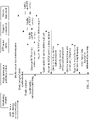
- FIG. 1 is a schematic flowchart of Embodiment 1 of a multi-device lip synchronization method according to an embodiment of the present invention.
- the method is used by a primary device to synchronously output audio and a video to at least one secondary device, and as shown in FIG. 1 , includes the following steps.
- the primary device collects a program clock reference (Program Clock Reference, PCR) based on a preset collection cycle.
- a program clock reference Program Clock Reference, PCR
- the primary device determines, based on the collected PCR, whether a preset condition is met, and sends a Real-Time Control Protocol (Real-Time Control Protocol, RTCP) packet to the secondary device when the preset condition is met, where a real-time streaming packet RTP time stamp header field in the RTCP packet carries the PCR, and a Network Time Protocol (Network Time protocol, NTP) field in the RTCP packet carries a sending time point of the RTCP packet.
- the preset condition is: a deviation between an actual PCR collection time interval of the primary device and the preset collection cycle is greater than a preset threshold.
- the preset threshold is, for example, a value ranging from -60 ms to 20 ms.
- the secondary device receives the RTCP packet sent by the primary device, and the secondary device corrects a system clock (System Time Clock, STC) of the secondary device based on the PCR, a program clock frequency of the primary device, a program clock frequency of the secondary device, and an RTCP delay.
- STC System Time Clock
- the secondary device may obtain the PCR, the sending time point of the RTCP packet, and a moment at which the RTCP packet is received.
- the RTCP delay is an RTCP transmission delay, and is a difference between the sending time point of the RTCP packet and the moment at which the RTCP packet is received.
- the RTCP packet carries an RTCP session identifier, and the RTCP session identifier is an identifier allocated by the primary device to distinguish between different secondary devices.
- the secondary device sends an RTCP session join request to the primary device, and the primary device sends the RTCP session identifier to the secondary device after receiving the RTCP session join request. Then the RTCP session identifier is added to the RTCP packet sent by the primary device to the secondary device.
- the secondary device corrects the STC of the secondary device based on the calculated STC correction value.
- the primary device copies an audio data frame from an audio pulse code modulation (Pulse Code Modulation, PCM) buffer of the primary device, packs the audio data frame into real-time streaming packets (Real Time Packet, RTP), and publishes the RTPs to a multicast service address and port, where a time stamp header field of the RTP carries a presentation time stamp corresponding to the audio data frame.
- PCM Packe Code Modulation
- the secondary device receives, based on the multicast service address and port sent by the primary device, the RTPs published by the primary device, splices the RTPs into the complete audio data frame, obtains, from the time stamp header field of the RTP packet, the presentation time stamp corresponding to the audio data frame, and puts the audio data frame into a PCM buffer of the secondary dcvicc.
- the audio data frame is, for example, an audio frame.
- the secondary device outputs the audio data frame in the audio PCM buffer based on the STC of the secondary device and the presentation time stamp of the audio data frame. Specifically, the secondary device synchronously plays the audio data frame in the audio PCM buffer based on the presentation time stamp of the audio data frame with reference to the STC of the secondary device.
- the primary device collects the PCR based on the preset cycle, and sends the RTCP packet to the secondary device when determining that the preset condition is met (in other words, time correction needs to be performed), where the RTCP packet carries the collected PCR and the sending time point of the RTCP packet.
- the secondary device corrects the STC of the secondary device based on the PCR, the program clock frequency of the primary device, the program clock frequency of the secondary device, and the RTCP delay.
- the secondary device receives, based on the multicast service address and port sent by the primary device, the RTPs published by the primary device, splices the RTPs into the complete audio data frame, obtains, from the time stamp header field of the RTP packet, the presentation time stamp corresponding to the audio data frame, and puts the audio data frame into the PCM buffer of the secondary device. Finally, the secondary device outputs the audio data frame in the audio PCM buffer with reference to the STC of the secondary device and the presentation time stamp of the audio data frame. Therefore, the primary device drives the secondary device, so that audio data and video data are synchronously output. This implements lip synchronization between the primary device and the secondary device, and provides good use experience for a user.
- FIG. 2 is a schematic flowchart of Embodiment 2 of a multi-device lip synchronization method according to an embodiment of the present invention. As shown in FIG. 2 , the method in this embodiment is based on the embodiment shown in FIG. 1 . If it is not a first time for the secondary device and the primary device to synchronously output audio data and video data, after audio data and video data are synchronously output for the first time, the program clock frequency of the primary device may be stored in the secondary device, and a corresponding identifier of the primary device may also be stored, so that the program clock frequency of the primary device and the identifier of the primary device may be directly used for synchronous output performed for a second time.
- the primary device needs to send the program clock frequency of the primary device to the secondary device before S103.
- a Simple Network Time Protocol Simple Network Time protocol (Simple Network Time protocol, SNTP) service address and port used by the secondary device to perform system time synchronization
- an RTCP service address and port used by the secondary device to receive the RTCP packet, the multicast service address and port, the program clock frequency of the primary device, a media format, and a time stamp frequency may be stored in the secondary device, and a corresponding identifier of the primary device may also be stored, so that the SNTP service address and port, the RTCP service address and port, the multicast service address and port, the program clock frequency of the primary device, the media format, the time stamp frequency, and the identifier of the
- the primary device sends media description information to the secondary device, where the media description information includes an SNTP service address and port, an RTCP service address and port, the multicast service address and port, the program clock frequency of the primary device, a media format, and a time stamp frequency.
- the primary device may publish the media description information by using the Hypertext Transfer Protocol.
- the secondary device receives the media description information sent by the primary device.
- the secondary device obtains the SNTP service address and port, the RTCP service address and port, the multicast service address and port, the program clock frequency of the primary device, the media format, and the time stamp frequency by parsing the media description information, performs system time synchronization based on the SNTP service address and port, and then receives, based on the RTCP service address and port, the RTCP packet sent by the primary device.
- the multicast service address and port are used by the secondary device to receive the RTPs published by the primary device.
- the media format is a format used by the primary device to perform compression coding on the audio data frame, and is used to by the secondary device to determine a corresponding decoding format.
- the time stamp frequency is used by the secondary device to adjust a time stamp between two frames of the secondary device based on a time stamp between two frames of the primary device.
- the primary device sends the media description information to the secondary device, and the secondary device performs system time synchronization based on the SNTP service address and port in the media description information. Then the primary device collects the PCR according to the preset cycle, and sends the RTCP packet to the secondary device when determining that the preset condition is met (in other words, time correction needs to be performed), where the RTCP packet carries the collected PCR and the sending time point of the RTCP packet.
- the secondary device corrects the STC of the secondary device based on the PCR, the program clock frequency of the primary device, the program clock frequency of the secondary device, and the RTCP delay.
- the secondary device receives, based on the multicast service address and port sent by the primary device, the RTPs published by the primary device, splices the RTPs into the complete audio data frame, obtains, from the time stamp header field of the RTP packet, the presentation time stamp corresponding to the audio data frame, and puts the audio data frame into the PCM buffer of the secondary device. Finally, the secondary device outputs the audio data frame in the audio PCM buffer with reference to the STC of the secondary device and the presentation time stamp of the audio data frame. Therefore, the primary device drives the secondary device, so that audio data and video data are synchronously output. This implements lip synchronization between the primary device and the secondary device, and provides good use experience for a user.
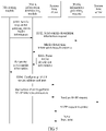
- FIG. 3 is a schematic diagram of a principle of a multi-device lip synchronization method according to an embodiment of the present invention.
- a media information publishing module for a primary device, a media information publishing module, a system time server, a program clock server, and an RTP packet server are newly added to an existing primary device (a media player), and for a secondary device, a media information downloading module, a system time client, a program clock client, an RTP packet client, and a program clock driver module are newly added to an existing secondary device.
- the media information publishing module, the system time server, the program clock server, the RTP packet server, the media information downloading module, the system time client, the program clock client, the RTP packet client, and the program clock driver module each may be a software module.
- the media information publishing module is configured to publish media description information, where the media description information includes an SNTP service address and port, an RTCP service address and port, a multicast service address and port, a program clock frequency of the primary device, a media format, and a time stamp frequency.
- the media information downloading module is configured to receive the media description information.
- the system time server and the system time client implement time synchronization between the secondary device and the primary device.
- the program clock server and the program clock client implement high-precision synchronization between program clocks of the secondary device and the primary device, for example, ensure that a program clock deviation is less than 20 ms (about a 1-frame PCM output delay).
- the program clock client cannot modulate a clock frequency to match the program clock server, corresponding clock frequency conversion needs to be performed on an SCR and a PTS.
- the RTP packet server and the RTP packet client establish an RTP channel for transmitting an audio data frame from the primary device to the secondary device.
- the program clock driver module of the secondary device is configured to perform output with reference to a clock of the program clock client when a PCM play driver module plays audio data.
- an original PCM play driver module of the primary device may be disconnected and not used, and the secondary device plays synchronously output audio.
- an original audio target decoder and an original audio PCM buffer (FIFO) of the secondary device are also disconnected, and the audio output by the primary device is played.
- an audio and video synchronization process of the primary device is as follows: An audio and video synchronization module of the primary device calculates a program clock reference value according to a synchronization policy (a PCR reference, a video stream reference, an audio stream reference, or an audio and video reference) of a target program and a lip synchronization algorithm and based on a PCR, an audio presentation time stamp (Presentation Time Stamp, PTS), and a video PTS that are input. Then the audio and video synchronization module compares the program clock reference value with a current system clock sample (SCR). When an offset exceeds a threshold (which is usually 100 ms to 200 ms), the program clock reference value is used to correct a system clock to obtain a corrected PCR.
- a synchronization policy a PCR reference, a video stream reference, an audio stream reference, or an audio and video reference
- a display output time sequence of the audio or the video is arranged based on a comparison between a PTS and the SCR. For example, when the PTS is less than or equal to the current sampling SCR, a current audio frame is output; or if the PTS is greater than the current sampling SCR, no audio frame is output.
- a video is normally output, and audio is not played by using the PCM play driver module, but is output to the secondary device by using the RTP packet server. Then the secondary device synchronously outputs the audio.
- FIG. 4 is a flowchart of interaction between modules when a primary device enables a media sharing service. As shown in FIG. 4 , the following steps are included.
- a monitoring module of the primary device After a monitoring module of the primary device is connected to a secondary device or finds a secondary device, the monitoring module enables a media sharing service procedure, including: enabling system time synchronization (by a system time server), enabling program clock synchronization (by a program clock server), enabling multicast (by an RTP packet server), and enabling media information publishing (by a media information publishing module).
- a media sharing service procedure including: enabling system time synchronization (by a system time server), enabling program clock synchronization (by a program clock server), enabling multicast (by an RTP packet server), and enabling media information publishing (by a media information publishing module).
- the media information publishing module publishes media description information, where the media description information includes an SNTP service address and port, an RTCP service address and port, a multicast service address and port, a program clock frequency of the primary device, a media format, and a time stamp frequency.
- the system time server performs system time synchronization based on the SNTP service address and port.
- the program clock server receives, based on the RTCP service address and port, an RTCP packet sent by the primary device, and performs program clock synchronization based on the RTCP packet.
- the RTP packet server publishes RTPs based on the multicast service address and port.
- FIG. 5 is a flowchart of interaction between modules when a secondary device queries a shared media resource. As shown in FIG. 5 , the following steps are included.
- a monitoring module of the secondary device sends a request for querying server media information to a media information downloading module.
- the media information downloading module sends a media description information request to a media information publishing module, and the media information publishing module returns a media description information request response that carries media description information, where the media description information includes an SNTP service address and port, an RTCP service address and port, a multicast service address and port, a program clock frequency of a primary device, a media format, and a time stamp frequency.
- the media information downloading module parses the media description information to obtain all service addresses and ports, the program clock frequency of the primary device, the media format, and the time stamp frequency.
- the monitoring module of the secondary device configures the SNTP service address and port, and starts a time client to perform SNTP time synchronization.
- time client and a system time server perform time synchronization.
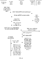
- FIG. 6 is a flowchart of interaction between modules when a secondary device synchronously plays a shared media resource. As shown in FIG. 6 , the following steps are included.
- a monitoring module of the secondary device sends a program clock synchronization request to a program clock client.
- the program clock client sends an RTCP session join request to a program clock server, and the program clock server returns an RTCP session identifier.
- the program clock server collects a PCR based on a preset collection cycle, and sends a PCR sampling value to the program clock client when a preset condition is met.
- the program clock client corrects an STC of the secondary device based on the PCR, a program clock frequency of a primary device, a program clock frequency of the secondary device, and an RTCP delay.
- the monitoring module of the secondary device sends a request for starting to receive an audio data frame to an RTP packet client.
- the RTP packet client sends a multicast group join request to an RTP packet server.
- the RTP packet server sends RTPs to the RTP packet client.
- the RTP packet client receives the RTPs, splices the RTPs into a complete audio data frame, obtains a presentation time stamp corresponding to the audio data frame from a time stamp header field of the RTP packet, and puts the audio data frame into a PCM buffer of the secondary device.
- a PCM play driver module outputs the audio data frame in the audio PCM buffer based on the STC of the secondary device and the presentation time stamp of the audio data frame.
- function modules of the primary device and the secondary device may be obtained through division based on the foregoing method examples.
- each function module may be obtained through division based on each function, or two or more functions may be integrated into one processing module.
- the integrated module may be implemented in a form of hardware, or may be implemented in a form of a software function module. It should be noted that the module division in the embodiments of the present invention is an example, and is merely logical function division. There may be another division manner in actual implementation.
- FIG. 7 is a schematic structural diagram of Embodiment 1 of a secondary device according to an embodiment of the present invention.
- the secondary device in this embodiment may include a first receiving module 11, a correction module 12, a second receiving module 13, a processing module 14, and an output module 15.
- the first receiving module 11 is configured to receive an RTCP packet sent by a primary device, where an RTP time stamp header field in the RTCP packet carries a program clock reference PCR cyclically collected by the primary device, and a Network Time Protocol NTP field in the RTCP packet carries a sending time point of the RTCP packet.
- the correction module 12 is configured to correct a system clock STC of the secondary device based on the PCR, a program clock frequency of the primary device, a program clock frequency of the secondary device, and an RTCP delay.
- the second receiving module 13 is configured to receive, based on a multicast service address and port sent by the primary device, RTPs published by the primary device.
- the processing module 14 is configured to: splice the RTPs into a complete audio data frame, obtain, from a time stamp header field of the RTP packet, a presentation time stamp PTS corresponding to the audio data frame, and put the audio data frame into an audio pulse code modulation PCM buffer of the secondary device.
- the output module 15 is configured to output the audio data frame in the audio PCM buffer based on the STC of the secondary device and the presentation time stamp of the audio data frame.
- FIG. 8 is a schematic structural diagram of Embodiment 2 of a secondary device according to an embodiment of the present invention.
- the secondary device in this embodiment may further include a sending module 16.
- the sending module 16 is configured to send an RTCP session join request to the primary device before the correction module 12 corrects the system clock STC of the secondary device based on the PCR, the program clock frequency of the primary device, the program clock frequency of the secondary device, and the RTCP delay, so that the primary device sends an RTCP session identifier to the secondary device.
- scr_correct scr_srv ⁇ scf_clt / scf_srv + ntp_rcv ⁇ ntp_snd ⁇ scf_
- the first receiving module 11 is further configured to: before receiving the Real-Time Control Protocol RTCP packet sent by the primary device, receive media description information sent by the primary device, where the media description information includes an SNTP service address and port, an RTCP service address and port, the multicast service address and port, the program clock frequency of the primary device, a media format, and a time stamp frequency.
- the processing module 14 is further configured to perform system time synchronization based on the SNTP service address and port.
- the first receiving module 11 is specifically configured to receive, based on the RTCP service address and port, the RTCP packet sent by the primary device.
- the secondary device in the embodiment shown in FIG. 7 or FIG. 8 may be configured to execute the technical solution of the method embodiment shown in FIG. 1 or FIG. 2 , and an implementation principle and a technical effect thereof are similar and are not described herein again.
- FIG. 9 is a schematic structural diagram of Embodiment 1 of a primary device according to an embodiment of the present invention.
- the primary device in this embodiment may include a collection module 21, a sending module 22, and a processing module 23.
- the collection module 21 is configured to collect a program clock reference PCR based on a preset collection cycle.
- the sending module 22 is configured to send a Real-Time Control Protocol RTCP packet to a secondary device when it is determined that a preset condition is met, where a real-time streaming packet RTP time stamp header field in the RTCP packet carries the PCR, and a Network Time Protocol NTP field in the RTCP packet carries a sending time point of the RTCP packet, so that the secondary device corrects a system clock STC of the secondary device based on the PCR, a program clock frequency of the primary device, a program clock frequency of the secondary device, and an RTCP delay.
- the processing module 23 is configured to: copy an audio data frame from an audio pulse code modulation PCM buffer of the primary device, pack the audio data frame into real-time streaming packets RTPs, and publish the RTPs to a multicast service address and port, where a time stamp header field of the RTP carries a presentation time stamp corresponding to the audio data frame, so that the secondary device receives the RTPs based on the multicast service address and port.
- FIG. 10 is a schematic structural diagram of Embodiment 2 of a primary device according to an embodiment of the present invention.
- the primary device in this embodiment may further include a receiving module 24.
- the receiving module 24 is configured to: before the sending module 22 sends the RTCP packet to the secondary device when it is determined that the preset condition is met, receive an RTCP session join request sent by the secondary device, and send an RTCP session identifier to the secondary device.
- the sending module 22 is further configured to: send media description information to the secondary device before the collection module 21 collects the program clock reference PCR based on the preset collection cycle, where the media description information includes an SNTP service address and port, an RTCP service address and port, the multicast service address and port, the program clock frequency of the primary device, a media format, and a time stamp frequency, the SNTP service address and port is used by the secondary device to perform system time synchronization, and the RTCP service address and port is used by the secondary device to receive, based on the RTCP service address and port, the RTCP packet sent by the primary device.
- the media description information includes an SNTP service address and port, an RTCP service address and port, the multicast service address and port, the program clock frequency of the primary device, a media format, and a time stamp frequency
- the SNTP service address and port is used by the secondary device to perform system time synchronization
- the RTCP service address and port is used by the secondary device to receive, based on the
- the preset condition is: a deviation between an actual PCR collection time interval of the primary device and the preset collection cycle is greater than a preset threshold.
- the preset threshold is 20 ms
- the preset condition is: scr_curr ⁇ scr_last ⁇ 1000 / scf_srv ⁇ cycle_read_x ⁇ 20 ; or scr_curr ⁇ scr_last ⁇ 1000 / scf_srv > cycle_read_x + 20 , where scr_curr is a currently collected clock value, scr last is a previously collected clock value, scf_srv is the program clock frequency of the primary device, and cycle read x is the preset collection cycle.
- the primary device in the embodiments shown in FIG. 9 and FIG. 10 may be configured to execute the technical solution of the method embodiment shown in FIG. 1 or FIG. 2 , and an implementation principle and a technical effect thereof are similar and are not described herein again.
- FIG. 11 is a schematic structural diagram of Embodiment 3 of a secondary device according to an embodiment of the present invention.
- the secondary device in this embodiment may include a receiver 31, a processor 32, and a transmitter 33.
- the receiver 31 is configured to receive an RTCP packet sent by a primary device, where an RTP time stamp header field in the RTCP packet carries a program clock reference PCR cyclically collected by the primary device, and a Network Time Protocol NTP field in the RTCP packet carries a sending time point of the RTCP packet.
- the processor 32 is configured to correct a system clock STC of the secondary device based on the PCR, a program clock frequency of the primary dcvicc, a program clock frequency of the secondary device, and an RTCP delay.
- the receiver 31 is further configured to receive, based on a multicast service address and port sent by the primary device, RTPs published by the primary device.
- the processor 32 is further configured to: splice the RTPs into a complete audio data frame, obtain, from a time stamp header field of the RTP packet, a presentation time stamp PTS corresponding to the audio data frame, and put the audio data frame into an audio pulse code modulation PCM buffer of the secondary device.
- the transmitter 33 is configured to output the audio data frame in the audio PCM buffer based on the STC of the secondary device and the presentation time stamp of the audio data frame.
- the transmitter 33 is further configured to send an RTCP session join request to the primary device before the correction module corrects the system clock STC of the secondary device based on the PCR, the program clock frequency of the primary device, the program clock frequency of the secondary device, and the RTCP delay, so that the primary device sends an RTCP session identifier to the secondary device.
- the receiver 31 is further configured to: before receiving the Real-Time Control Protocol RTCP packet sent by the primary device, receive media description information sent by the primary device, where the media description information includes an SNTP service address and port, an RTCP service address and port, the multicast service address and port, the program clock frequency of the primary device, a media format, and a time stamp frequency.
- the processor 32 is further configured to perform system time synchronization based on the SNTP service address and port.
- the receiver 31 is specifically configured to receive, based on the RTCP service address and port, the RTCP packet sent by the primary device.
- the secondary device in this embodiment may be configured to execute the technical solution of the method embodiment shown in FIG. 1 or FIG. 2 , and an implementation principle and a technical effect thereof are similar and are not described herein again.
- FIG. 12 is a schematic structural diagram of Embodiment 3 of a primary device according to an embodiment of the present invention.
- the primary device in this embodiment may include a processor 41 and a transmitter 42.
- the processor 41 is configured to collect a program clock reference PCR based on a preset collection cycle.
- the transmitter 42 is configured to send a Real-Time Control Protocol RTCP packet to a secondary device when it is determined that a preset condition is met, where a real-time streaming packet RTP time stamp header field in the RTCP packet carries the PCR, and a Network Time Protocol NTP field in the RTCP packet carries a sending time point of the RTCP packet, so that the secondary device corrects a system clock STC of the secondary device based on the PCR, a program clock frequency of the primary device, a program clock frequency of the secondary device, and an RTCP delay.
- the processor 41 is further configured to: copy an audio data frame from an audio pulse code modulation PCM buffer of the primary device, pack the audio data frame into real-time streaming packets RTPs, and publish the RTPs to a multicast service address and port, where a time stamp header field of the RTP carries a presentation time stamp corresponding to the audio data frame, so that the secondary device receives the RTPs based on the multicast service address and port.
- FIG. 13 is a schematic structural diagram of Embodiment 4 of a primary device according to an embodiment of the present invention.
- the primary device in this embodiment may further include a receiver 43.
- the receiver 43 is configured to: before the transmitter 42 sends the RTCP packet to the secondary device when it is determined that the preset condition is met, receive an RTCP session join request sent by the secondary device, and send an RTCP session identifier to the secondary device.
- the transmitter 42 is further configured to: send media description information to the secondary device before the processor 41 collects the program clock reference PCR based on the preset collection cycle, where the media description information includes an SNTP service address and port, an RTCP service address and port, the multicast service address and port, the program clock frequency of the primary device, a media format, and a time stamp frequency, the SNTP service address and port is used by the secondary device to perform system time synchronization, and the RTCP service address and port is used by the secondary device to receive, based on the RTCP service address and port, the RTCP packet sent by the primary device.
- the media description information includes an SNTP service address and port, an RTCP service address and port, the multicast service address and port, the program clock frequency of the primary device, a media format, and a time stamp frequency
- the SNTP service address and port is used by the secondary device to perform system time synchronization
- the RTCP service address and port is used by the secondary device to receive, based on the RT
- the preset condition is: a deviation between an actual PCR collection time interval of the primary device and the preset collection cycle is greater than a preset threshold.
- the preset threshold is 20 ms
- the preset condition is: scr_curr ⁇ scr_last ⁇ 1000 / scf_srv ⁇ cycle_read_x ⁇ 20 ; scr_curr ⁇ scr_last ⁇ 1000 / scf_srv > cycle_read_x + 20 , where scr_curr is a currently collected clock value, scr last is a previously collected clock value, scf_srv is the program clock frequency of the primary device, and cycle read x is the preset collection cycle.
- the primary device in the embodiments shown in FIG. 12 and FIG. 13 may be configured to execute the technical solution of the method embodiment shown in FIG. 1 or FIG. 2 , and an implementation principle and a technical effect thereof are similar and are not described herein again.
- each aspect of the embodiments of the present invention or a possible implementation of each aspect may be specifically implemented as a system, a method, or a computer program product. Therefore, each aspect of the embodiments of the present invention or a possible implementation of each aspect may use forms of hardware only embodiments, software only embodiments (including firmware, resident software, and the like), or embodiments with a combination of software and hardware, which are uniformly referred to as "circuit", "module", or “system” herein.
- each aspect of the embodiments of the present invention or the possible implementation of each aspect may take a form of a computer program product, where the computer program product is computer-readable program code stored in a computer-readable medium.
- the computer-readable medium may be a computer-readable signal medium or a computer-readable storage medium.
- the computer-readable storage medium includes but is not limited to an electronic, magnetic, optical, electromagnetic, infrared, or semi-conductive system, device, or apparatus, or any appropriate combination thereof, such as a random access memory (RAM), a read-only memory (ROM), an erasable programmable read only memory (EPROM or flash memory), an optical fiber, and a compact disc read-only memory (CD-ROM).
- a processor in a computer reads the computer-readable program code stored in the computer-readable medium, so that the processor can perform a function and an action specified in each step or a combination of steps in a flowchart; an apparatus is generated to implement a function and an action specified in each block or a combination of blocks in a block diagram.
- All computer-readable program code may be executed on a local computer of a user, or some may be executed on a local computer of a user as a standalone software package, or some may be executed on a local computer of a user while some is executed on a remote computer, or all the code may be executed on a remote computer or a server.
- each step in the flowcharts or functions specified in each block in the block diagrams may not occur in the illustrated order.
- two steps or blocks that depend on a function and are shown in sequence may be actually executed concurrently, or sometimes these blocks may be executed in reverse order.
Landscapes
- Engineering & Computer Science (AREA)
- Signal Processing (AREA)
- Multimedia (AREA)
- Computer Networks & Wireless Communication (AREA)
- Computer Security & Cryptography (AREA)
- Synchronisation In Digital Transmission Systems (AREA)
- Two-Way Televisions, Distribution Of Moving Picture Or The Like (AREA)
- Data Exchanges In Wide-Area Networks (AREA)
Description
- Embodiments of the present invention relate to the field of communications technologies, and in particular, to a multi-device lip synchronization method and a device.
- As Wi-Fi speakers and Bluetooth speakers are widely applied, an increasing quantity of users favor an application in which an audio and video playing device sends audio data to a Wi-Fi speaker or a Bluetooth speaker in a wireless connection manner, and then the audio and video playing device plays a video and the Wi-Fi speaker or the Bluetooth speaker plays audio. In this application, a most important issue is to ensure lip synchronization, so that a user can obtain good use experience.
- In an existing process of using a Bluetooth speaker, a Bluetooth driver module in the audio and video playing device reads audio pulse code modulation (Pulse Code Modulation, PCM) data from an audio PCM buffer of the audio and video playing device, and sends the audio PCM data to the Bluetooth speaker in real time by using a Bluetooth protocol. A Bluetooth audio driver module in the Bluetooth speaker receives the PCM data according to the Bluetooth protocol, and sends the PCM data to an audio PCM buffer of the Bluetooth speaker in real time. A PCM play driver module in the Bluetooth speaker directly reads the audio PCM data from the audio PCM buffer of the Bluetooth speaker and plays and outputs the audio PCM data.
- It may be learned that the Bluetooth speaker resolves only a problem of cross-device audio output, but cannot implement lip synchronization between devices. The same is true when the foregoing method is applied to a Wi-Fi speaker. In addition, for the Wi-Fi speaker, a forwarding delay of a Wi-Fi router further exacerbates asynchronization between audio output and video output. Therefore, how to implement multi-device lip synchronization is a problem that needs to be resolved.
-
US 2008/304571 A1 relates to a content receiving apparatus comprising: decoding means for receiving, from a content providing apparatus provided at an encoder side, a plurality of encoded video frames to which video time-stamps based on reference clock for the encoder side are attached and a plurality of encoded audio frames to which audio time-stamps based on a reference clock for the encoder side are attached, and for decoding the encoded video frames and the encoded audio frames; storing means for storing a plurality of video frames that the decoding means has obtained by decoding the encoded video frames and a plurality of audio frames that the decoding means has obtained by decoding the encoded audio frames; calculating means for calculating a time difference resulting from a gap between a clock frequency of a reference clock for the encoder side and a clock frequency of a system time clock for the decoder side; and timing-adjusting means for adjusting a timing of outputting the plurality of video frames, one by one, in accordance with the time difference and on the basis of a timing of outputting the plurality of audio frames, one by one. - The invention is defined by the appended independent claims. Further detailed embodiments are defined in the dependent claims. The invention resolves the problem of how to implement lip synchronization when a plurality of devices synchronously play a video and audio.
- According to a first aspect, an embodiment of the present invention provides a multi-device lip synchronization method, where the method is used by a primary device to synchronously output audio and a video to at least one secondary device, and includes: receiving, by the secondary device, a Real-Time Control Protocol RTCP packet sent by the primary device, where a real-time streaming packet RTP time stamp header field in the RTCP packet carries a program clock reference PCR cyclically collected by the primary device, and a Network Time Protocol NTP field in the RTCP packet carries a sending time point of the RTCP packet; correcting, by the secondary device, a system clock STC of the secondary device based on the PCR, a program clock frequency of the primary device, a program clock frequency of the secondary device, and an RTCP delay; receiving, by the secondary device based on a multicast service address and port sent by the primary device, RTPs published by the primary device, splicing the RTPs into a complete audio data frame, obtaining, from a time stamp header field of the RTP packet, a presentation time stamp PTS corresponding to the audio data frame, and putting the audio data frame into an audio pulse code modulation PCM buffer of the secondary device; and outputting, by the secondary device, the audio data frame in the audio PCM buffer based on the STC of the secondary device and the presentation time stamp of the audio data frame. Therefore, the primary device drives the secondary device, so that audio data and video data are synchronously output. This implements lip synchronization between the primary device and the secondary device, and provides good use experience for a user.
- Before the receiving, by the secondary device, a Real-Time Control Protocol RTCP packet sent by the primary device, the method further includes: receiving, by the secondary device, media description information sent by the primary device, where the media description information includes a Simple Network Time Protocol SNTP service address and port, an RTCP service address and port, the multicast service address and port, the program clock frequency of the primary device, a media format, and a time stamp frequency; and performing, by the secondary device, system time synchronization based on the SNTP service address and port; and
the receiving, by the secondary device, a Real-Time Control Protocol RTCP packet sent by the primary device includes:
receiving, by the secondary device based on the RTCP service address and port, the RTCP packet sent by the primary device. - In a possible design, the RTCP packet carries an RTCP session identifier, and before the correcting, by the secondary device, a system clock STC of the secondary device based on the PCR, a program clock frequency of the primary device, a program clock frequency of the secondary device, and an RTCP delay, the method further includes: sending, by the secondary device, an RTCP session join request to the primary device, so that the primary device sends the RTCP session identifier to the secondary device.
- In a possible design, the correcting, by the secondary device, a system clock STC of the secondary device based on the PCR, a program clock frequency of the primary device, a program clock frequency of the secondary device, and an RTCP delay includes: calculating, by the secondary device, an STC correction value scr_correct of the secondary device according to the following formula:

- scf clt is the program clock frequency of the secondary device, scf srv is the program clock frequency of the primary device, ntp rcv is a moment at which the RTCP packet is received, and scr_srv and ntp_snd are sending time points of the PCR and the RTCP packet, respectively; and
- correcting, by the secondary device, the STC of the secondary device based on the calculated STC correction value.
- According to a second aspect, an embodiment of the present invention provides a multi-device lip synchronization method, where the method is used by a primary device to synchronously output audio and a video to at least one secondary device, and includes: collecting, by the primary device, a program clock reference PCR based on a preset collection cycle; sending, by the primary device, a Real-Time Control Protocol RTCP packet to the secondary device when determining that a preset condition is met, where a real-time streaming packet RTP time stamp header field in the RTCP packet carries the PCR, and a Network Time Protocol NTP field in the RTCP packet carries a sending time point of the RTCP packet, so that the secondary device is able to correct a system clock STC of the secondary device based on the PCR, a program clock frequency of the primary device, a program clock frequency of the secondary device, and an RTCP delay; and copying, by the primary device, an audio data frame from an audio pulse code modulation PCM buffer of the primary device, packing the audio data frame into real-time streaming packets RTPs, and publishing the RTPs to a multicast service address and port, where a time stamp header field of the RTP carries a presentation time stamp corresponding to the audio data frame, so that the secondary device receives the RTPs based on the multicast service address and port. Therefore, the primary device drives the secondary device, so that audio data and video data are synchronously output. This implements lip synchronization between the primary device and the secondary device, and provides good use experience for a user. Before the collecting, by the primary device, a program clock reference PCR based on a preset collection cycle, the method further includes: sending, by the primary device, media description information to the secondary device, where the media description information includes a Simple Network Time Protocol SNTP service address and port, an RTCP service address and port, the multicast service address and port, the program clock frequency of the primary device, a media format, and a time stamp frequency, the SNTP service address and port is used by the secondary device to perform system time synchronization, and the RTCP service address and port is used by the secondary device to receive, based on the RTCP service address and port, the RTCP packet sent by the primary device.
- In a possible design, the RTCP packet carries an RTCP session identifier, and before the sending, by the primary device, a Real-Time Control Protocol RTCP packet to the secondary device when determining that a preset condition is met, the method further includes: receiving, by the primary device, an RTCP session join request sent by the secondary device, and sending the RTCP session identifier to the secondary device.
- In a possible design, the preset condition is: a deviation between an actual PCR collection time interval of the primary device and the preset collection cycle is greater than a preset threshold.
- In a possible design, the preset threshold is 20 ms, and the preset condition is:


- According to a third aspect, an embodiment of the present invention provides a secondary device, including:
a first receiving module, configured to receive a Real-Time Control Protocol RTCP packet sent by a primary device, where a real-time streaming packet RTP time stamp header field in the RTCP packet carries a program clock reference PCR cyclically collected by the primary device, and a Network Time Protocol NTP field in the RTCP packet carries a sending time point of the RTCP packet; a correction module, configured to correct a system clock STC of the secondary device based on the PCR, a program clock frequency of the primary device, a program clock frequency of the secondary device, and an RTCP delay; a second receiving module, configured to receive, based on a multicast service address and port sent by the primary device, RTPs published by the primary device; a processing module, configured to: splice the RTPs into a complete audio data frame, obtain, from a time stamp header field of the RTP packet, a presentation time stamp PTS corresponding to the audio data frame, and put the audio data frame into an audio pulse code modulation PCM buffer of the secondary device; and an output module, configured to output the audio data frame in the audio PCM buffer based on the STC of the secondary device and the presentation time stamp of the audio data frame. Therefore, the primary device drives the secondary device, so that audio data and video data are synchronously output. - This implements lip synchronization between the primary device and the secondary device, and provides good use experience for a user. The first receiving module is further configured to: before receiving the Real-Time Control Protocol RTCP packet sent by the primary device, receive media description information sent by the primary device, where the media description information includes a Simple Network Time Protocol SNTP service address and port, an RTCP service address and port, the multicast service address and port, the program clock frequency of the primary device, a media format, and a time stamp frequency; and the processing module is further configured to perform system time synchronization based on the SNTP service address and port; and
the first receiving module is specifically configured to receive, based on the RTCP service address and port, the RTCP packet sent by the primary device. - In a possible design, the RTCP packet carries an RTCP session identifier, and the secondary device further includes: a sending module, configured to send an RTCP session join request to the primary device before the correction module corrects the system clock STC of the secondary device based on the PCR, the program clock frequency of the primary device, the program clock frequency of the secondary device, and the RTCP delay, so that the primary device sends the RTCP session identifier to the secondary device.
- In a possible design, the correction module is specifically configured to: calculate an STC correction value scr_correct of the secondary device according to the following formula:

- scf_clt is the program clock frequency of the secondary device, scf_srv is the program clock frequency of the primary device, ntp rcv is a moment at which the RTCP packet is received, and scr_srv and ntp_snd are sending time points of the PCR and the RTCP packet, respectively; and
- correct the STC of the secondary device based on the calculated STC correction value.
- According to a fourth aspect, an embodiment of the present invention provides a system composed by a primary device and at least one secondary device, wherein the primary device includes: a collection module, configured to collect a program clock reference PCR based on a preset collection cycle; a sending module, configured to send a Real-Time Control Protocol RTCP packet to a secondary device when it is determined that a preset condition is met, where a real-time streaming packet RTP time stamp header field in the RTCP packet carries the PCR, and a Network Time Protocol NTP field in the RTCP packet carries a sending time point of the RTCP packet, so that the secondary device corrects a system clock STC of the secondary device based on the PCR, a program clock frequency of the primary device, a program clock frequency of the secondary device, and an RTCP delay; and a processing module, configured to: copy an audio data frame from an audio pulse code modulation PCM buffer of the primary device, pack the audio data frame into real-time streaming packets RTPs, and publish the RTPs to a multicast service address and port, where a time stamp header field of the RTP carries a presentation time stamp corresponding to the audio data frame, so that the secondary device receives the RTPs based on the multicast service address and port. Therefore, the primary device drives the secondary device, so thataudio data and video data are synchronously output. This implements lip synchronization between the primary device and the secondary device, and provides good use experience for a user. The sending module is further configured to: send media description information to the secondary device before the collection module collects the program clock reference PCR based on the preset collection cycle, where the media description information includes a Simple Network Time Protocol SNTP service address and port, an RTCP service address and port, the multicast service address and port, the program clock frequency of the primary device, a media format, and a time stamp frequency, the SNTP service address and port is used by the secondary device to perform system time synchronization, and the RTCP service address and port is used by the secondary device to receive, based on the RTCP service address and port, the RTCP packet sent by the primary device.
- In a possible design, the RTCP packet carries an RTCP session identifier, and the primary device further includes: a receiving module, configured to: before the sending module sends the Real-Time Control Protocol RTCP packet to the secondary device when determining that the preset condition is met, receive an RTCP session join request sent by the secondary device, and send the RTCP session identifier to the secondary device.
- In a possible design, the preset condition is: a deviation between an actual PCR collection time interval of the primary device and the preset collection cycle is greater than a preset threshold.
- In a possible design, the preset threshold is 20 ms, and the preset condition is:


- An embodiment of the present invention provides a terminal, including a receiver, a processor, and a transmitter. The receiver is configured to receive data from outside of the terminal. The transmitter is configured to send data to an external device. The processor is configured to perform the method according to the first aspect or the second aspect. An embodiment of the present invention further provides a computer storage medium, configured to store a computer software instruction used by the secondary device or the primary device in any of the foregoing aspects, and the computer software instruction includes a method or a program designed for performing the foregoing aspect.
- An embodiment of the present invention further provides a data processing system, including a module configured to perform the method according to the first aspect or the second aspect.
- An embodiment of the present invention further provides a computer program, configured to perform the method according to the first aspect or the second aspect.
-
-
FIG. 1 is a schematic flowchart of Embodiment 1 of a multi-device lip synchronization method according to an embodiment of the present invention; -
FIG. 2 is a schematic flowchart of Embodiment 2 of a multi-device lip synchronization method according to an embodiment of the present invention; -
FIG. 3 is a schematic diagram of a principle of a multi-device lip synchronization method according to an embodiment of the present invention; -
FIG. 4 is a flowchart of interaction between modules when a primary device enables a media sharing service; -
FIG. 5 is a flowchart of interaction between modules when a secondary device queries a shared media resource; -
FIG. 6 is a flowchart of interaction between modules when a secondary device synchronously plays a shared media resource; -
FIG. 7 is a schematic structural diagram of Embodiment 1 of a secondary device according to an embodiment of the present invention; -
FIG. 8 is a schematic structural diagram of Embodiment 2 of a secondary device according to an embodiment of the present invention; -
FIG. 9 is a schematic structural diagram of Embodiment 1 of a primary device according to an embodiment of the present invention; -
FIG. 10 is a schematic structural diagram of Embodiment 2 of a primary device according to an embodiment of the present invention; -
FIG. 11 is a schematic structural diagram of Embodiment 3 of a secondary device according to an embodiment of the present invention; -
FIG. 12 is a schematic structural diagram of Embodiment 3 of a primary device according to an embodiment of the present invention; and -
FIG. 13 is a schematic structural diagram of Embodiment 4 of a primary device according to an embodiment of the present invention. - The technical solutions in the embodiments of the present invention may be applied to various communications systems in a wireless cellular network, for example, a Global System for Mobile Communications (Global System of Mobile communication, GSM), a Code Division Multiple Access (Code Division Multiple Access, CDMA) system, a Wideband Code Division Multiple Access (Wideband Code Division Multiple Access Wireless, WCDMA) system, a general packet radio service (General Packet Radio Service, GPRS) system, an LTE system, and a Universal Mobile Telecommunications System (Universal Mobile Telecommunications System, UMTS). This is not limited in the embodiments of the present invention.
- The technical solutions in the embodiments of the present invention are mainly applied to a scenario of how to ensure lip synchronization when a primary device and one or more secondary devices synchronously play video data and audio data. Lip synchronization means that video data played by the primary device synchronizes with audio data played by the secondary device, so that a playing effect that a lip movement synchronizes with voice can be achieved when a user is watching a video. The primary device is connected to the secondary device through Wi-Fi or in another manner. The primary device plays video data and the secondary device plays audio data. The primary device supports audio and video output synchronization, such as a mobile phone, a set-top box (Set-Top Box, STB), or a television box (Over The Top, OTT). The secondary device may be a device such as a Wi-Fi speaker, and the secondary device can play audio data.
- According to a multi-device lip synchronization method and a device that are provided in the embodiments of the present invention, one primary device can drive a plurality of secondary devices, so that audio data and video data are synchronously output. This implements lip synchronization between the primary device and the secondary devices, and provides good use experience for a user. The technical solutions provided in the embodiments of the present invention are described in detail below with reference to the accompanying drawings.
-
FIG. 1 is a schematic flowchart of Embodiment 1 of a multi-device lip synchronization method according to an embodiment of the present invention. The method is used by a primary device to synchronously output audio and a video to at least one secondary device, and as shown inFIG. 1 , includes the following steps. - S101. The primary device collects a program clock reference (Program Clock Reference, PCR) based on a preset collection cycle.
- S102. The primary device determines, based on the collected PCR, whether a preset condition is met, and sends a Real-Time Control Protocol (Real-Time Control Protocol, RTCP) packet to the secondary device when the preset condition is met, where a real-time streaming packet RTP time stamp header field in the RTCP packet carries the PCR, and a Network Time Protocol (Network Time protocol, NTP) field in the RTCP packet carries a sending time point of the RTCP packet. The preset condition is: a deviation between an actual PCR collection time interval of the primary device and the preset collection cycle is greater than a preset threshold. The preset threshold is, for example, a value ranging from -60 ms to 20 ms. 20 ms is used as an example, and the preset condition is:


- S103. The secondary device receives the RTCP packet sent by the primary device, and the secondary device corrects a system clock (System Time Clock, STC) of the secondary device based on the PCR, a program clock frequency of the primary device, a program clock frequency of the secondary device, and an RTCP delay.
- Because the real-time streaming packet RTP time stamp header field in the RTCP packet carries the PCR, and the NTP field in the RTCP packet carries the sending time point of the RTCP packet, after the secondary device receives the RTCP packet, the secondary device may obtain the PCR, the sending time point of the RTCP packet, and a moment at which the RTCP packet is received. The RTCP delay is an RTCP transmission delay, and is a difference between the sending time point of the RTCP packet and the moment at which the RTCP packet is received. The RTCP packet carries an RTCP session identifier, and the RTCP session identifier is an identifier allocated by the primary device to distinguish between different secondary devices. Specifically, the secondary device sends an RTCP session join request to the primary device, and the primary device sends the RTCP session identifier to the secondary device after receiving the RTCP session join request. Then the RTCP session identifier is added to the RTCP packet sent by the primary device to the secondary device.
- Specifically, the secondary device may calculate an STC correction value scr_correct of the secondary device according to the following formula:

- Then the secondary device corrects the STC of the secondary device based on the calculated STC correction value.
- S104. The primary device copies an audio data frame from an audio pulse code modulation (Pulse Code Modulation, PCM) buffer of the primary device, packs the audio data frame into real-time streaming packets (Real Time Packet, RTP), and publishes the RTPs to a multicast service address and port, where a time stamp header field of the RTP carries a presentation time stamp corresponding to the audio data frame.
- S105. The secondary device receives, based on the multicast service address and port sent by the primary device, the RTPs published by the primary device, splices the RTPs into the complete audio data frame, obtains, from the time stamp header field of the RTP packet, the presentation time stamp corresponding to the audio data frame, and puts the audio data frame into a PCM buffer of the secondary dcvicc. The audio data frame is, for example, an audio frame.
- S106. The secondary device outputs the audio data frame in the audio PCM buffer based on the STC of the secondary device and the presentation time stamp of the audio data frame. Specifically, the secondary device synchronously plays the audio data frame in the audio PCM buffer based on the presentation time stamp of the audio data frame with reference to the STC of the secondary device.
- According to the multi-device lip synchronization method provided in this embodiment, the primary device collects the PCR based on the preset cycle, and sends the RTCP packet to the secondary device when determining that the preset condition is met (in other words, time correction needs to be performed), where the RTCP packet carries the collected PCR and the sending time point of the RTCP packet. The secondary device corrects the STC of the secondary device based on the PCR, the program clock frequency of the primary device, the program clock frequency of the secondary device, and the RTCP delay. Then the secondary device receives, based on the multicast service address and port sent by the primary device, the RTPs published by the primary device, splices the RTPs into the complete audio data frame, obtains, from the time stamp header field of the RTP packet, the presentation time stamp corresponding to the audio data frame, and puts the audio data frame into the PCM buffer of the secondary device. Finally, the secondary device outputs the audio data frame in the audio PCM buffer with reference to the STC of the secondary device and the presentation time stamp of the audio data frame. Therefore, the primary device drives the secondary device, so that audio data and video data are synchronously output. This implements lip synchronization between the primary device and the secondary device, and provides good use experience for a user.
-
FIG. 2 is a schematic flowchart of Embodiment 2 of a multi-device lip synchronization method according to an embodiment of the present invention. As shown inFIG. 2 , the method in this embodiment is based on the embodiment shown inFIG. 1 . If it is not a first time for the secondary device and the primary device to synchronously output audio data and video data, after audio data and video data are synchronously output for the first time, the program clock frequency of the primary device may be stored in the secondary device, and a corresponding identifier of the primary device may also be stored, so that the program clock frequency of the primary device and the identifier of the primary device may be directly used for synchronous output performed for a second time. If it is the first time for the secondary device and the primary device to synchronously output audio data and video data, the primary device needs to send the program clock frequency of the primary device to the secondary device before S103. Likewise, if it is not the first time for the secondary device and the primary device to synchronously output audio data and video data, after audio data and video data are synchronously output for the first time, a Simple Network Time Protocol (Simple Network Time protocol, SNTP) service address and port used by the secondary device to perform system time synchronization, an RTCP service address and port used by the secondary device to receive the RTCP packet, the multicast service address and port, the program clock frequency of the primary device, a media format, and a time stamp frequency may be stored in the secondary device, and a corresponding identifier of the primary device may also be stored, so that the SNTP service address and port, the RTCP service address and port, the multicast service address and port, the program clock frequency of the primary device, the media format, the time stamp frequency, and the identifier of the primary device may be directly used for synchronous output performed for a second time. If it is the first time for the secondary device and the primary device to synchronously output audio data and video data, before S101, the method may further include the following steps. - S107. The primary device sends media description information to the secondary device, where the media description information includes an SNTP service address and port, an RTCP service address and port, the multicast service address and port, the program clock frequency of the primary device, a media format, and a time stamp frequency. Specifically, the primary device may publish the media description information by using the Hypertext Transfer Protocol.
- S108. The secondary device receives the media description information sent by the primary device. The secondary device obtains the SNTP service address and port, the RTCP service address and port, the multicast service address and port, the program clock frequency of the primary device, the media format, and the time stamp frequency by parsing the media description information, performs system time synchronization based on the SNTP service address and port, and then receives, based on the RTCP service address and port, the RTCP packet sent by the primary device. The multicast service address and port are used by the secondary device to receive the RTPs published by the primary device. The media format is a format used by the primary device to perform compression coding on the audio data frame, and is used to by the secondary device to determine a corresponding decoding format. The time stamp frequency is used by the secondary device to adjust a time stamp between two frames of the secondary device based on a time stamp between two frames of the primary device.
- A subsequent procedure is the same as that shown in
FIG. 1 . Details are not described herein again. - According to the multi-dcvicc lip synchronization method provided in this embodiment, the primary device sends the media description information to the secondary device, and the secondary device performs system time synchronization based on the SNTP service address and port in the media description information. Then the primary device collects the PCR according to the preset cycle, and sends the RTCP packet to the secondary device when determining that the preset condition is met (in other words, time correction needs to be performed), where the RTCP packet carries the collected PCR and the sending time point of the RTCP packet. The secondary device corrects the STC of the secondary device based on the PCR, the program clock frequency of the primary device, the program clock frequency of the secondary device, and the RTCP delay. Then the secondary device receives, based on the multicast service address and port sent by the primary device, the RTPs published by the primary device, splices the RTPs into the complete audio data frame, obtains, from the time stamp header field of the RTP packet, the presentation time stamp corresponding to the audio data frame, and puts the audio data frame into the PCM buffer of the secondary device. Finally, the secondary device outputs the audio data frame in the audio PCM buffer with reference to the STC of the secondary device and the presentation time stamp of the audio data frame. Therefore, the primary device drives the secondary device, so that audio data and video data are synchronously output. This implements lip synchronization between the primary device and the secondary device, and provides good use experience for a user.
- A schematic diagram of a principle of audio output from the primary device to the secondary device is described in detail below with reference to the accompanying drawings, module composition inside the primary device and the secondary device, and an interaction process between modules.
-
FIG. 3 is a schematic diagram of a principle of a multi-device lip synchronization method according to an embodiment of the present invention. As shown inFIG. 3 , in this embodiment of the present invention, for a primary device, a media information publishing module, a system time server, a program clock server, and an RTP packet server are newly added to an existing primary device (a media player), and for a secondary device, a media information downloading module, a system time client, a program clock client, an RTP packet client, and a program clock driver module are newly added to an existing secondary device. The media information publishing module, the system time server, the program clock server, the RTP packet server, the media information downloading module, the system time client, the program clock client, the RTP packet client, and the program clock driver module each may be a software module. The media information publishing module is configured to publish media description information, where the media description information includes an SNTP service address and port, an RTCP service address and port, a multicast service address and port, a program clock frequency of the primary device, a media format, and a time stamp frequency. The media information downloading module is configured to receive the media description information. The system time server and the system time client implement time synchronization between the secondary device and the primary device. The program clock server and the program clock client implement high-precision synchronization between program clocks of the secondary device and the primary device, for example, ensure that a program clock deviation is less than 20 ms (about a 1-frame PCM output delay). When the program clock client cannot modulate a clock frequency to match the program clock server, corresponding clock frequency conversion needs to be performed on an SCR and a PTS. The RTP packet server and the RTP packet client establish an RTP channel for transmitting an audio data frame from the primary device to the secondary device. The program clock driver module of the secondary device is configured to perform output with reference to a clock of the program clock client when a PCM play driver module plays audio data. - It should be noted that as shown in
FIG. 3 , after the secondary device is connected to the primary device, an original PCM play driver module of the primary device may be disconnected and not used, and the secondary device plays synchronously output audio. After the secondary device is connected to the primary device, an original audio target decoder and an original audio PCM buffer (FIFO) of the secondary device are also disconnected, and the audio output by the primary device is played. - Specifically, an audio and video synchronization process of the primary device is as follows: An audio and video synchronization module of the primary device calculates a program clock reference value according to a synchronization policy (a PCR reference, a video stream reference, an audio stream reference, or an audio and video reference) of a target program and a lip synchronization algorithm and based on a PCR, an audio presentation time stamp (Presentation Time Stamp, PTS), and a video PTS that are input. Then the audio and video synchronization module compares the program clock reference value with a current system clock sample (SCR). When an offset exceeds a threshold (which is usually 100 ms to 200 ms), the program clock reference value is used to correct a system clock to obtain a corrected PCR. During output of a media stream such as audio or a video, a display output time sequence of the audio or the video is arranged based on a comparison between a PTS and the SCR. For example, when the PTS is less than or equal to the current sampling SCR, a current audio frame is output; or if the PTS is greater than the current sampling SCR, no audio frame is output. After the primary device is connected to the secondary device, a video is normally output, and audio is not played by using the PCM play driver module, but is output to the secondary device by using the RTP packet server. Then the secondary device synchronously outputs the audio.
-
FIG. 4 is a flowchart of interaction between modules when a primary device enables a media sharing service. As shown inFIG. 4 , the following steps are included. - S201. After a monitoring module of the primary device is connected to a secondary device or finds a secondary device, the monitoring module enables a media sharing service procedure, including: enabling system time synchronization (by a system time server), enabling program clock synchronization (by a program clock server), enabling multicast (by an RTP packet server), and enabling media information publishing (by a media information publishing module).
- S202. The media information publishing module publishes media description information, where the media description information includes an SNTP service address and port, an RTCP service address and port, a multicast service address and port, a program clock frequency of the primary device, a media format, and a time stamp frequency.
- Then the system time server performs system time synchronization based on the SNTP service address and port. The program clock server receives, based on the RTCP service address and port, an RTCP packet sent by the primary device, and performs program clock synchronization based on the RTCP packet. The RTP packet server publishes RTPs based on the multicast service address and port.
-
FIG. 5 is a flowchart of interaction between modules when a secondary device queries a shared media resource. As shown inFIG. 5 , the following steps are included. - S301. A monitoring module of the secondary device sends a request for querying server media information to a media information downloading module.
- S302. The media information downloading module sends a media description information request to a media information publishing module, and the media information publishing module returns a media description information request response that carries media description information, where the media description information includes an SNTP service address and port, an RTCP service address and port, a multicast service address and port, a program clock frequency of a primary device, a media format, and a time stamp frequency.
- S303. The media information downloading module parses the media description information to obtain all service addresses and ports, the program clock frequency of the primary device, the media format, and the time stamp frequency.
- S304. The monitoring module of the secondary device configures the SNTP service address and port, and starts a time client to perform SNTP time synchronization.
- Finally, the time client and a system time server perform time synchronization.
-
FIG. 6 is a flowchart of interaction between modules when a secondary device synchronously plays a shared media resource. As shown inFIG. 6 , the following steps are included. - S401. A monitoring module of the secondary device sends a program clock synchronization request to a program clock client.
- S402. The program clock client sends an RTCP session join request to a program clock server, and the program clock server returns an RTCP session identifier.
- S403. The program clock server collects a PCR based on a preset collection cycle, and sends a PCR sampling value to the program clock client when a preset condition is met.
- S404. The program clock client corrects an STC of the secondary device based on the PCR, a program clock frequency of a primary device, a program clock frequency of the secondary device, and an RTCP delay.
- S405. The monitoring module of the secondary device sends a request for starting to receive an audio data frame to an RTP packet client.
- S406. The RTP packet client sends a multicast group join request to an RTP packet server.
- S407. The RTP packet server sends RTPs to the RTP packet client.
- S408. The RTP packet client receives the RTPs, splices the RTPs into a complete audio data frame, obtains a presentation time stamp corresponding to the audio data frame from a time stamp header field of the RTP packet, and puts the audio data frame into a PCM buffer of the secondary device.
- S409. A PCM play driver module outputs the audio data frame in the audio PCM buffer based on the STC of the secondary device and the presentation time stamp of the audio data frame.
- In the embodiments of the present invention, function modules of the primary device and the secondary device may be obtained through division based on the foregoing method examples. For example, each function module may be obtained through division based on each function, or two or more functions may be integrated into one processing module. The integrated module may be implemented in a form of hardware, or may be implemented in a form of a software function module. It should be noted that the module division in the embodiments of the present invention is an example, and is merely logical function division. There may be another division manner in actual implementation.
-
FIG. 7 is a schematic structural diagram of Embodiment 1 of a secondary device according to an embodiment of the present invention. As shown inFIG. 7 , the secondary device in this embodiment may include afirst receiving module 11, acorrection module 12, asecond receiving module 13, aprocessing module 14, and anoutput module 15. Thefirst receiving module 11 is configured to receive an RTCP packet sent by a primary device, where an RTP time stamp header field in the RTCP packet carries a program clock reference PCR cyclically collected by the primary device, and a Network Time Protocol NTP field in the RTCP packet carries a sending time point of the RTCP packet. Thecorrection module 12 is configured to correct a system clock STC of the secondary device based on the PCR, a program clock frequency of the primary device, a program clock frequency of the secondary device, and an RTCP delay. Thesecond receiving module 13 is configured to receive, based on a multicast service address and port sent by the primary device, RTPs published by the primary device. Theprocessing module 14 is configured to: splice the RTPs into a complete audio data frame, obtain, from a time stamp header field of the RTP packet, a presentation time stamp PTS corresponding to the audio data frame, and put the audio data frame into an audio pulse code modulation PCM buffer of the secondary device. Theoutput module 15 is configured to output the audio data frame in the audio PCM buffer based on the STC of the secondary device and the presentation time stamp of the audio data frame. -
FIG. 8 is a schematic structural diagram of Embodiment 2 of a secondary device according to an embodiment of the present invention. As shown inFIG. 8 , based on the secondary device shown inFIG. 7 , further, the secondary device in this embodiment may further include a sending module 16. The sending module 16 is configured to send an RTCP session join request to the primary device before thecorrection module 12 corrects the system clock STC of the secondary device based on the PCR, the program clock frequency of the primary device, the program clock frequency of the secondary device, and the RTCP delay, so that the primary device sends an RTCP session identifier to the secondary device. - Further, the
correction module 12 is specifically configured to: calculate an STC correction value scr_correct of the secondary device according to the following formula:
- Further, the
first receiving module 11 is further configured to: before receiving the Real-Time Control Protocol RTCP packet sent by the primary device, receive media description information sent by the primary device, where the media description information includes an SNTP service address and port, an RTCP service address and port, the multicast service address and port, the program clock frequency of the primary device, a media format, and a time stamp frequency. Theprocessing module 14 is further configured to perform system time synchronization based on the SNTP service address and port. Thefirst receiving module 11 is specifically configured to receive, based on the RTCP service address and port, the RTCP packet sent by the primary device. - The secondary device in the embodiment shown in
FIG. 7 or FIG. 8 may be configured to execute the technical solution of the method embodiment shown inFIG. 1 orFIG. 2 , and an implementation principle and a technical effect thereof are similar and are not described herein again. -
FIG. 9 is a schematic structural diagram of Embodiment 1 of a primary device according to an embodiment of the present invention. As shown inFIG. 9 , the primary device in this embodiment may include acollection module 21, a sendingmodule 22, and aprocessing module 23. Thecollection module 21 is configured to collect a program clock reference PCR based on a preset collection cycle. The sendingmodule 22 is configured to send a Real-Time Control Protocol RTCP packet to a secondary device when it is determined that a preset condition is met, where a real-time streaming packet RTP time stamp header field in the RTCP packet carries the PCR, and a Network Time Protocol NTP field in the RTCP packet carries a sending time point of the RTCP packet, so that the secondary device corrects a system clock STC of the secondary device based on the PCR, a program clock frequency of the primary device, a program clock frequency of the secondary device, and an RTCP delay. Theprocessing module 23 is configured to: copy an audio data frame from an audio pulse code modulation PCM buffer of the primary device, pack the audio data frame into real-time streaming packets RTPs, and publish the RTPs to a multicast service address and port, where a time stamp header field of the RTP carries a presentation time stamp corresponding to the audio data frame, so that the secondary device receives the RTPs based on the multicast service address and port. -
FIG. 10 is a schematic structural diagram of Embodiment 2 of a primary device according to an embodiment of the present invention. As shown inFIG. 10 , based on the primary device shown inFIG. 9 , further, the primary device in this embodiment may further include a receivingmodule 24. The receivingmodule 24 is configured to: before the sendingmodule 22 sends the RTCP packet to the secondary device when it is determined that the preset condition is met, receive an RTCP session join request sent by the secondary device, and send an RTCP session identifier to the secondary device. - Further, the sending
module 22 is further configured to: send media description information to the secondary device before thecollection module 21 collects the program clock reference PCR based on the preset collection cycle, where the media description information includes an SNTP service address and port, an RTCP service address and port, the multicast service address and port, the program clock frequency of the primary device, a media format, and a time stamp frequency, the SNTP service address and port is used by the secondary device to perform system time synchronization, and the RTCP service address and port is used by the secondary device to receive, based on the RTCP service address and port, the RTCP packet sent by the primary device. - The preset condition is: a deviation between an actual PCR collection time interval of the primary device and the preset collection cycle is greater than a preset threshold.
- Optionally, the preset threshold is 20 ms, and the preset condition is:


- The primary device in the embodiments shown in
FIG. 9 and FIG. 10 may be configured to execute the technical solution of the method embodiment shown inFIG. 1 orFIG. 2 , and an implementation principle and a technical effect thereof are similar and are not described herein again. -
FIG. 11 is a schematic structural diagram of Embodiment 3 of a secondary device according to an embodiment of the present invention. As shown inFIG. 11 , the secondary device in this embodiment may include areceiver 31, aprocessor 32, and atransmitter 33. Thereceiver 31 is configured to receive an RTCP packet sent by a primary device, where an RTP time stamp header field in the RTCP packet carries a program clock reference PCR cyclically collected by the primary device, and a Network Time Protocol NTP field in the RTCP packet carries a sending time point of the RTCP packet. Theprocessor 32 is configured to correct a system clock STC of the secondary device based on the PCR, a program clock frequency of the primary dcvicc, a program clock frequency of the secondary device, and an RTCP delay. Thereceiver 31 is further configured to receive, based on a multicast service address and port sent by the primary device, RTPs published by the primary device. Theprocessor 32 is further configured to: splice the RTPs into a complete audio data frame, obtain, from a time stamp header field of the RTP packet, a presentation time stamp PTS corresponding to the audio data frame, and put the audio data frame into an audio pulse code modulation PCM buffer of the secondary device. Thetransmitter 33 is configured to output the audio data frame in the audio PCM buffer based on the STC of the secondary device and the presentation time stamp of the audio data frame. - Further, the
transmitter 33 is further configured to send an RTCP session join request to the primary device before the correction module corrects the system clock STC of the secondary device based on the PCR, the program clock frequency of the primary device, the program clock frequency of the secondary device, and the RTCP delay, so that the primary device sends an RTCP session identifier to the secondary device. - Further, the
processor 32 is specifically configured to: calculate an STC correction value scr_correct of the secondary device according to the following formula:
- Further, the
receiver 31 is further configured to: before receiving the Real-Time Control Protocol RTCP packet sent by the primary device, receive media description information sent by the primary device, where the media description information includes an SNTP service address and port, an RTCP service address and port, the multicast service address and port, the program clock frequency of the primary device, a media format, and a time stamp frequency. Theprocessor 32 is further configured to perform system time synchronization based on the SNTP service address and port. Thereceiver 31 is specifically configured to receive, based on the RTCP service address and port, the RTCP packet sent by the primary device. - The secondary device in this embodiment may be configured to execute the technical solution of the method embodiment shown in
FIG. 1 orFIG. 2 , and an implementation principle and a technical effect thereof are similar and are not described herein again. -
FIG. 12 is a schematic structural diagram of Embodiment 3 of a primary device according to an embodiment of the present invention. As shown inFIG. 12 , the primary device in this embodiment may include aprocessor 41 and atransmitter 42. Theprocessor 41 is configured to collect a program clock reference PCR based on a preset collection cycle. Thetransmitter 42 is configured to send a Real-Time Control Protocol RTCP packet to a secondary device when it is determined that a preset condition is met, where a real-time streaming packet RTP time stamp header field in the RTCP packet carries the PCR, and a Network Time Protocol NTP field in the RTCP packet carries a sending time point of the RTCP packet, so that the secondary device corrects a system clock STC of the secondary device based on the PCR, a program clock frequency of the primary device, a program clock frequency of the secondary device, and an RTCP delay. Theprocessor 41 is further configured to: copy an audio data frame from an audio pulse code modulation PCM buffer of the primary device, pack the audio data frame into real-time streaming packets RTPs, and publish the RTPs to a multicast service address and port, where a time stamp header field of the RTP carries a presentation time stamp corresponding to the audio data frame, so that the secondary device receives the RTPs based on the multicast service address and port. -
FIG. 13 is a schematic structural diagram of Embodiment 4 of a primary device according to an embodiment of the present invention. As shown inFIG. 13 , based on the primary device shown inFIG. 12 , further, the primary device in this embodiment may further include areceiver 43. Thereceiver 43 is configured to: before thetransmitter 42 sends the RTCP packet to the secondary device when it is determined that the preset condition is met, receive an RTCP session join request sent by the secondary device, and send an RTCP session identifier to the secondary device. - Further, the
transmitter 42 is further configured to: send media description information to the secondary device before theprocessor 41 collects the program clock reference PCR based on the preset collection cycle, where the media description information includes an SNTP service address and port, an RTCP service address and port, the multicast service address and port, the program clock frequency of the primary device, a media format, and a time stamp frequency, the SNTP service address and port is used by the secondary device to perform system time synchronization, and the RTCP service address and port is used by the secondary device to receive, based on the RTCP service address and port, the RTCP packet sent by the primary device. - The preset condition is: a deviation between an actual PCR collection time interval of the primary device and the preset collection cycle is greater than a preset threshold.
- Optionally, the preset threshold is 20 ms, and the preset condition is:


- The primary device in the embodiments shown in
FIG. 12 and FIG. 13 may be configured to execute the technical solution of the method embodiment shown inFIG. 1 orFIG. 2 , and an implementation principle and a technical effect thereof are similar and are not described herein again. - The embodiments in this specification are all described in a progressive manner, for same or similar parts in the embodiments, refer to these embodiments. Each embodiment focuses on a difference from other embodiments. Especially, a system or apparatus embodiment is basically similar to a method embodiment, and therefore is described briefly. For related parts, refer to partial descriptions in the method embodiment.
- A person of ordinary skill in the art may understand that each aspect of the embodiments of the present invention or a possible implementation of each aspect may be specifically implemented as a system, a method, or a computer program product. Therefore, each aspect of the embodiments of the present invention or a possible implementation of each aspect may use forms of hardware only embodiments, software only embodiments (including firmware, resident software, and the like), or embodiments with a combination of software and hardware, which are uniformly referred to as "circuit", "module", or "system" herein. In addition, each aspect of the embodiments of the present invention or the possible implementation of each aspect may take a form of a computer program product, where the computer program product is computer-readable program code stored in a computer-readable medium.
- The computer-readable medium may be a computer-readable signal medium or a computer-readable storage medium. The computer-readable storage medium includes but is not limited to an electronic, magnetic, optical, electromagnetic, infrared, or semi-conductive system, device, or apparatus, or any appropriate combination thereof, such as a random access memory (RAM), a read-only memory (ROM), an erasable programmable read only memory (EPROM or flash memory), an optical fiber, and a compact disc read-only memory (CD-ROM).
- A processor in a computer reads the computer-readable program code stored in the computer-readable medium, so that the processor can perform a function and an action specified in each step or a combination of steps in a flowchart; an apparatus is generated to implement a function and an action specified in each block or a combination of blocks in a block diagram. All computer-readable program code may be executed on a local computer of a user, or some may be executed on a local computer of a user as a standalone software package, or some may be executed on a local computer of a user while some is executed on a remote computer, or all the code may be executed on a remote computer or a server. It should also be noted that in some alternative implementation solutions, each step in the flowcharts or functions specified in each block in the block diagrams may not occur in the illustrated order. For example, two steps or blocks that depend on a function and are shown in sequence may be actually executed concurrently, or sometimes these blocks may be executed in reverse order.
Claims (14)
- A multi-device lip synchronization method, wherein the method is applied to a primary device and at least one secondary device synchronously output video and audio, wherein the primary device outputs video and the at least one secondary device outputs audio, wherein the primary device is connected to the at least one secondary device through Wi-Fi, and the method comprises:receiving (S102), by the secondary device, a Real-Time Transport Control Protocol, RTCP, packet sent by the primary device, wherein a Real-Time Transport Protocol, RTP, time stamp header field in the RTCP packet carries a program clock reference, PCR, cyclically collected by the primary device, and a Network Time Protocol, NTP, field in the RTCP packet carries a sending time point of the RTCP packet;correcting (S103), by the secondary device, a system clock, STC, of the secondary device based on the PCR, a program clock frequency of the primary device, a program clock frequency of the secondary device, and a RTCP delay;receiving (S105), by the secondary device based on a multicast service address and port sent by the primary device, RTPs published by the primary device, splicing the RTPs into a complete audio data frame, obtaining, from a time stamp header field of the RTP packet, a presentation time stamp, PTS, corresponding to the audio data frame, and storing the audio data frame into an audio pulse code modulation, PCM, buffer of the secondary device; andoutputting (S106), by the secondary device, the audio data frame in the audio PCM buffer based on the STC of the secondary device and the presentation time stamp of the audio data frame, wherein before the receiving (S102), by the secondary device, a Real-Time Transport Control Protocol, RTCP, packet sent by the primary device, the method further comprises:receiving (S107), by the secondary device, media description information sent by the primary device, wherein the media description information comprises a Simple Network Time Protocol, SNTP, service address and port, a RTCP service address and port, the multicast service address and port, the program clock frequency of the primary device, a media format, and a time stamp frequency;performing (S108), by the secondary device, system time synchronization based on the SNTP service address and port; andthe receiving (S102), by the secondary device, a Real-Time Transport Control Protocol, RTCP, packet sent by the primary device comprises:receiving, by the secondary device based on the RTCP service address and port, the RTCP packet sent by the primary device.
- The method according to claim 1, wherein the RTCP packet carries a RTCP session identifier, and before the correcting (S103), by the secondary device, a system clock, STC, of the secondary device based on the PCR, a program clock frequency of the primary device, a program clock frequency of the secondary device, and a RTCP delay, the method further comprises: sending, by the secondary device, a RTCP session join request to the primary device, so that the primary device sends the RTCP session identifier to the secondary device.
- The method according to claim 1 or 2, wherein the correcting (S103), by the secondary device, a system clock, STC, of the secondary device based on the PCR, a program clock frequency of the primary device, a program clock frequency of the secondary device, and a RTCP delay comprises:calculating, by the secondary device, a STC correction value scr_correct of the secondary device according to the following formula:
 scf_clt is the program clock frequency of the secondary device, scf_srv is the program clock frequency of the primary device, ntp rcv is a moment at which the RTCP packet is received, and scr_srv and ntp_snd are sending time points of the PCR and the RTCP packet, respectively; andcorrecting, by the secondary device, the STC of the secondary device based on the calculated STC correction value.
 - A multi-device lip synchronization method, wherein the method is applied to a primary device and at least one secondary device synchronously output video and audio, wherein the primary device outputs video and the at least one secondary device outputs audio, wherein the primary device is connected to the at least one secondary device through Wi-Fi, and the method comprises:collecting (S101), by the primary device, a program clock reference, PCR, based on a preset collection cycle;sending (S102), by the primary device, a Real-Time Transport Control Protocol, RTCP, packet to the secondary device when determining that a preset condition is met, wherein a Real-Time Transport Protocol, RTP, time stamp header field in the RTCP packet carries the PCR, and a Network Time Protocol, NTP, field in the RTCP packet carries a sending time point of the RTCP packet, so that the secondary device is able to correct a system clock, STC, of the secondary device based on the PCR, a program clock frequency of the primary device, a program clock frequency of the secondary device, and a RTCP delay; andcopying (S104), by the primary device, an audio data frame from an audio pulse code modulation, PCM, buffer of the primary device, packing the audio data frame into Real-Time Transport Protocols, RTPs, and publishing the RTPs to a multicast service address and port, wherein a time stamp header field of the RTP carries a presentation time stamp corresponding to the audio data frame, so that the secondary device receives the RTPs based on the multicast service address and port, wherein before the collecting (S101), by the primary device, a program clock reference, PCR, based on a preset collection cycle, the method further comprises:
sending (S107), by the primary device, media description information to the secondary device, wherein the media description information comprises a Simple Network Time Protocol, SNTP, service address and port, a RTCP service address and port, the multicast service address and port, the program clock frequency of the primary device, a media format, and a time stamp frequency, the SNTP service address and port is used by the secondary device to perform system time synchronization, and the RTCP service address and port is used by the secondary device to receive, based on the RTCP service address and port, the RTCP packet sent by the primary device. - The method according to claim 4, wherein the RTCP packet carries a RTCP session identifier, and before the sending (S102), by the primary device, a Real-Time Transport Control Protocol, RTCP, packet to the secondary device when determining that a preset condition is met, the method further comprises:
receiving, by the primary device, a RTCP session join request sent by the secondary device, and sending the RTCP session identifier to the secondary device. - The method according to any one of claims 4 or 5, wherein the preset condition is:
a deviation between an actual PCR collection time interval of the primary device and the preset collection cycle is greater than a preset threshold. - The method according to claim 6, wherein the preset threshold is 20 ms, and the preset condition is:

or
scr_curr is a currently collected clock value, scr last is a previously collected clock value, scf_srv is the program clock frequency of the primary device, and cycle_read_x is the preset collection cycle. - A secondary device, comprising:a first receiving module (11), configured to receive a Real-Time Transport Control Protocol, RTCP, packet sent by primary device, wherein a Real-Time Transport Protocol, RTP, time stamp header field in the RTCP packet carries a program clock reference, PCR, cyclically collected by the primary device, and a Network Time Protocol, NTP, field in the RTCP packet carries a sending time point of the RTCP packet;a correction module (12), configured to correct a system clock, STC, of the secondary device based on the PCR, a program clock frequency of the primary device, a program clock frequency of the secondary device, and a RTCP delay;a second receiving module (13), configured to receive, based on a multicast service address and port sent by the primary device, RTPs published by the primary device;a processing module (14), configured to: splice the RTPs into a complete audio data frame, obtain, from a time stamp header field of the RTP packet, a presentation time stamp, PTS, corresponding to the audio data frame, and put the audio data frame into an audio pulse code modulation, PCM, buffer of the secondary device; andan output module (15), configured to output the audio data frame in the audio PCM buffer based on the STC of the secondary device and the presentation time stamp of the audio data frame, wherein the first receiving module (11) is further configured to:before receiving the Real-Time Transport Control Protocol, RTCP, packet sent by the primary device, receive media description information sent by the primary device, wherein the media description information comprises a Simple Network Time Protocol, SNTP, service address and port, a RTCP service address and port, the multicast service address and port, the program clock frequency of the primary device, a media format, and a time stamp frequency;the processing module (14) is further configured to perform system time synchronization based on the SNTP service address and port; andthe first receiving module (11) is specifically configured to receive, based on the RTCP service address and port, the RTCP packet sent by the primary device.
- The secondary device according to claim 8, wherein the RTCP packet carries a RTCP
session identifier, and the secondary device further comprises:a sending module (16), configured to send a RTCP session join request to the primarydevice before the correction module (12) corrects the system clock, STC, of the secondary device based on the PCR, the program clock frequency of the primary device, the program clock frequency of the secondary device, and the RTCP delay, so that the primary device sends the RTCP session identifier to the secondary device. - The secondary device according to claim 8 or 9, wherein the correction module (12) is specifically configured to:calculate a STC correction value scr_correct of the secondary device according to the following formula:
 correct the STC of the secondary device based on the calculated STC correction value.
 - A system for multi-device lip synchronization, composed by a primary device and at least one secondary device, the primary device comprising:a collection module (21), configured to collect a program clock reference, PCR, based on a preset collection cycle;a sending module (22), configured to send a Real-Time Transport Control Protocol, RTCP, packet to the secondary device when a preset condition is met, wherein a Real-Time Transport Protocol, RTP, time stamp header field in the RTCP packet carries the PCR, and a Network Time Protocol, NTP, field in the RTCP packet carries a sending time point of the RTCP packet, so that the secondary device corrects a system clock, STC, of the secondary device based on the PCR, a program clock frequency of the primary device, a program clock frequency of the secondary device, and a RTCP delay; anda processing module (23), configured to: copy an audio data frame from an audio pulse code modulation, PCM, buffer of the primary device, pack the audio data frame into Real-Time Transport Protocols, RTPs, and publish the RTPs to a multicast service address and port, wherein a time stamp header field of the RTP carries a presentation time stamp corresponding to the audio data frame, so that the secondary device receives the RTPs based on the multicast service address and port, wherein the sending module (22) is further configured to:
send media description information to the secondary device before the collection module (21) collects the program clock reference PCR based on the preset collection cycle, wherein the media description information comprises a Simple Network Time Protocol SNTP service address and port, a RTCP service address and port, the multicast service address and port, the program clock frequency of the primary device, a media format, and a time stamp frequency, the SNTP service address and port is used by the secondary device to perform system time synchronization, and the RTCP service address and port is used by the secondary device to receive, based on the RTCP service address and port, the RTCP packet sent by the primary device. - The system according to claim 11, wherein the RTCP packet carries a RTCP session identifier, and the primary device further comprises:
a receiving module (24), configured to: before the sending module (22) sends the Real-Time Transport Control Protocol, RTCP, packet to the secondary device when the preset condition is met, receive a RTCP session join request sent by the secondary device, and send the RTCP session identifier to the secondary device. - The system according to any one of claims 11 or 12, wherein the preset condition is:
a deviation between an actual PCR collection time interval of the primary device and the preset collection cycle is greater than a preset threshold. - The system according to claim 13, wherein the preset threshold is 20 ms, and the preset condition is:


Applications Claiming Priority (1)
| Application Number | Priority Date | Filing Date | Title |
|---|---|---|---|
| PCT/CN2017/077925 WO2018170852A1 (en) | 2017-03-23 | 2017-03-23 | Method and device for lip-speech synchronization among multiple devices |
Publications (4)
| Publication Number | Publication Date |
|---|---|
| EP3591908A1 EP3591908A1 (en) | 2020-01-08 |
| EP3591908A4 EP3591908A4 (en) | 2020-01-08 |
| EP3591908B1 EP3591908B1 (en) | 2022-02-09 |
| EP3591908B9 true EP3591908B9 (en) | 2022-04-06 |
Family
ID=63584723
Family Applications (1)
| Application Number | Title | Priority Date | Filing Date |
|---|---|---|---|
| EP17902312.2A Active EP3591908B9 (en) | 2017-03-23 | 2017-03-23 | Method and device for lip-speech synchronization among multiple devices |
Country Status (4)
| Country | Link |
|---|---|
| US (1) | US11146611B2 (en) |
| EP (1) | EP3591908B9 (en) |
| CN (1) | CN109565466B (en) |
| WO (1) | WO2018170852A1 (en) |
Families Citing this family (12)
| Publication number | Priority date | Publication date | Assignee | Title |
|---|---|---|---|---|
| DE112019006635T5 (en) * | 2019-01-08 | 2021-09-30 | Sony Group Corporation | RECEIVING DEVICE AND METHOD, AND TRANSMISSION DEVICE AND METHOD |
| CN111954050B (en) * | 2019-05-14 | 2022-08-30 | 福州瑞芯微电子股份有限公司 | Method and system for synchronizing videos among multiple devices |
| US11394480B2 (en) * | 2019-08-23 | 2022-07-19 | Bose Corporation | Systems and methods for synchronizing device clocks |
| US11005585B1 (en) | 2019-12-31 | 2021-05-11 | Juniper Networks, Inc. | Transporting client timing information across a network |
| WO2021159329A1 (en) * | 2020-02-12 | 2021-08-19 | 深圳元戎启行科技有限公司 | Streaming media network latency determination method and apparatus, computer device, readable storage medium, and remote driving system |
| CN112130616B (en) * | 2020-09-28 | 2022-08-23 | 北京小米松果电子有限公司 | Clock synchronization method, device and storage medium |
| CN112887773A (en) * | 2021-01-22 | 2021-06-01 | 昆腾微电子股份有限公司 | Synchronization method and device of audio equipment |
| CN114827696B (en) * | 2021-01-29 | 2023-06-27 | 华为技术有限公司 | Method for synchronously playing audio and video data of cross-equipment and electronic equipment |
| CN113613125B (en) * | 2021-04-26 | 2024-07-09 | 珠海市杰理科技股份有限公司 | Audio synchronous control method, device, audio equipment and system |
| CN113676470B (en) * | 2021-08-17 | 2023-02-07 | 维沃移动通信有限公司 | Method and device for obtaining RTCP report information |
| CN115801859B (en) * | 2022-11-10 | 2024-06-04 | 广东美的智能科技有限公司 | Connection method, industrial control device and system between configuration equipment |
| CN116600162A (en) * | 2023-06-21 | 2023-08-15 | 济南大学 | Progressive audio and video time stamp synchronization method and system |
Family Cites Families (26)
| Publication number | Priority date | Publication date | Assignee | Title |
|---|---|---|---|---|
| JP3255308B2 (en) | 1992-12-18 | 2002-02-12 | ソニー株式会社 | Data playback device |
| US5486864A (en) | 1993-05-13 | 1996-01-23 | Rca Thomson Licensing Corporation | Differential time code method and apparatus as for a compressed video signal |
| JPH11261958A (en) | 1998-03-09 | 1999-09-24 | Sony Corp | Video editing apparatus and video editing method |
| US20030066094A1 (en) * | 2001-09-29 | 2003-04-03 | Koninklijke Philips Electronics N.V. | Robust method for recovering a program time base in MPEG-2 transport streams and achieving audio/video sychronization |
| US7657645B2 (en) * | 2004-02-05 | 2010-02-02 | Sharp Laboratories Of America, Inc. | System and method for transporting MPEG2TS in RTP/UDP/IP |
| CN1286314C (en) | 2004-08-05 | 2006-11-22 | 联合信源数字音视频技术(北京)有限公司 | Method and its device for keeping display synchronization in video frequency decoding system |
| KR101263522B1 (en) | 2004-09-02 | 2013-05-13 | 소니 주식회사 | Content receiver, video-audio output timing control method, and content providing system |
| US8068515B2 (en) * | 2005-06-22 | 2011-11-29 | Cisco Technology, Inc. | Faster multimedia synchronization of broadcast streams using router caching of RTCP packets |
| US20070047590A1 (en) | 2005-08-26 | 2007-03-01 | Nokia Corporation | Method for signaling a device to perform no synchronization or include a synchronization delay on multimedia stream |
| CN100442858C (en) | 2005-10-11 | 2008-12-10 | 华为技术有限公司 | Lip synchronization method and device for multimedia real-time transmission in packet network |
| CN101438256B (en) * | 2006-03-07 | 2011-12-21 | 索尼株式会社 | Information processing device, information communication system, information processing method |
| CN101179484A (en) | 2006-11-09 | 2008-05-14 | 华为技术有限公司 | A method and system for synchronizing between different media streams |
| CN101123611B (en) * | 2007-09-25 | 2012-05-23 | 中兴通讯股份有限公司 | A method for sending streaming media data |
| CN100579238C (en) * | 2008-02-22 | 2010-01-06 | 上海华平信息技术股份有限公司 | Method for synchronous playback of audio and video buffers |
| EP2254342A1 (en) | 2009-05-18 | 2010-11-24 | Albis Technologies AG | Method for the synchronisation of an audio and videostream |
| CN101710997A (en) | 2009-11-04 | 2010-05-19 | 中兴通讯股份有限公司 | MPEG-2 (Moving Picture Experts Group-2) system based method and system for realizing video and audio synchronization |
| CN101848396B (en) | 2009-11-30 | 2012-10-17 | 深圳市华曦达科技股份有限公司 | Audio/video synchronization and anti-shaking method of transport stream |
| CN102547299A (en) | 2010-12-30 | 2012-07-04 | 福建星网视易信息系统有限公司 | Audio and video synchronous control method based on moving picture experts group (MPEG)-2 |
| CN102421035A (en) * | 2011-12-31 | 2012-04-18 | 青岛海信宽带多媒体技术有限公司 | Method and device for realizing audio and video synchronization of digital television |
| CN102665141B (en) | 2012-05-16 | 2014-04-09 | 哈尔滨工业大学深圳研究生院 | AVS (audio video standard) audio and video presynchronizing method based on RTP (real time protocol) package |
| CN103888813A (en) | 2012-12-21 | 2014-06-25 | 北京计算机技术及应用研究所 | Audio and video synchronization realization method and system |
| US9978395B2 (en) * | 2013-03-15 | 2018-05-22 | Vocollect, Inc. | Method and system for mitigating delay in receiving audio stream during production of sound from audio stream |
| EP3020204B1 (en) * | 2013-07-09 | 2022-04-27 | Koninklijke KPN N.V. | Synchronized data processing between receivers |
| CN103428584A (en) | 2013-08-01 | 2013-12-04 | 珠海全志科技股份有限公司 | Method and device for keeping synchronization of audio and video on multimedia playing platform |
| CN105917655B (en) * | 2014-01-13 | 2019-07-09 | Lg电子株式会社 | The device and method of broadcasted content are sent or received via one or more network |
| EP3226570A1 (en) * | 2016-03-31 | 2017-10-04 | Thomson Licensing | Synchronizing audio and video signals rendered on different devices |
-
2017
- 2017-03-23 US US16/496,306 patent/US11146611B2/en active Active
- 2017-03-23 EP EP17902312.2A patent/EP3591908B9/en active Active
- 2017-03-23 CN CN201780049030.3A patent/CN109565466B/en active Active
- 2017-03-23 WO PCT/CN2017/077925 patent/WO2018170852A1/en not_active Ceased
Also Published As
| Publication number | Publication date |
|---|---|
| EP3591908A1 (en) | 2020-01-08 |
| CN109565466A (en) | 2019-04-02 |
| EP3591908A4 (en) | 2020-01-08 |
| WO2018170852A1 (en) | 2018-09-27 |
| US20200099734A1 (en) | 2020-03-26 |
| US11146611B2 (en) | 2021-10-12 |
| EP3591908B1 (en) | 2022-02-09 |
| CN109565466B (en) | 2020-11-06 |
Similar Documents
| Publication | Publication Date | Title |
|---|---|---|
| EP3591908B9 (en) | Method and device for lip-speech synchronization among multiple devices | |
| CN111147907B (en) | Method, device and system for synchronously playing multiple intelligent terminals and intelligent terminal | |
| CN109906613B (en) | Multi-mode synchronized rendering of audio and video | |
| EP3118855B1 (en) | Audio synchronous playing method, device and system | |
| US8155157B2 (en) | Method and apparatus for synchronizing applications of terminals in communication network | |
| CN110049011B (en) | Method and apparatus for media data delivery control | |
| US11368634B2 (en) | Audio stream and video stream synchronous switching method and apparatus | |
| EP3258697B1 (en) | Transmission apparatus, transmission method, reception apparatus, and reception method | |
| WO2015023463A1 (en) | Clock synchronization for multi-processor/multi-chipset solution | |
| US10547884B2 (en) | Technique for transmitting and receiving system time information in broadcasting system | |
| KR20210032988A (en) | Use of broadcast physical layer for one-way time transmission in Coordinated Universal Time to receivers | |
| EP3240337B1 (en) | Data transmission method and device | |
| CN104703054B (en) | Communicator and communication means | |
| EP3404922A1 (en) | Fast dvb channel switching method, apparatus, and system | |
| EP3262845B1 (en) | Delay compensation for broadcast adaptive bitrate streaming | |
| JP2012513139A (en) | Method for synchronizing transport streams in a multiplexer with an external coprocessor | |
| US10903921B2 (en) | Method and device for providing heterogeneous network-based broadcast service | |
| JP2018534878A (en) | Set data packet lifetime limits to minimize congestion and contention | |
| EP3343979B1 (en) | Apparatus and method for providing data service using heterogeneous network | |
| CN112714490A (en) | Time delay calibration method and device, computer equipment and computer readable storage medium | |
| CN111327923B (en) | Audio stream switching method and device | |
| US10142249B2 (en) | Method and apparatus for determining buffer status of user equipment | |
| CN114554242B (en) | Live broadcast method and readable storage medium | |
| US20250048298A1 (en) | Synchronization of data by a user equipment in connection with connected devices | |
| EP4564825A1 (en) | Data transmission method and apparatus |
Legal Events
| Date | Code | Title | Description |
|---|---|---|---|
| STAA | Information on the status of an ep patent application or granted ep patent |
Free format text: STATUS: THE INTERNATIONAL PUBLICATION HAS BEEN MADE |
|
| PUAI | Public reference made under article 153(3) epc to a published international application that has entered the european phase |
Free format text: ORIGINAL CODE: 0009012 |
|
| STAA | Information on the status of an ep patent application or granted ep patent |
Free format text: STATUS: REQUEST FOR EXAMINATION WAS MADE |
|
| 17P | Request for examination filed |
Effective date: 20191002 |
|
| A4 | Supplementary search report drawn up and despatched |
Effective date: 20191209 |
|
| AK | Designated contracting states |
Kind code of ref document: A1 Designated state(s): AL AT BE BG CH CY CZ DE DK EE ES FI FR GB GR HR HU IE IS IT LI LT LU LV MC MK MT NL NO PL PT RO RS SE SI SK SM TR |
|
| AX | Request for extension of the european patent |
Extension state: BA ME |
|
| DAV | Request for validation of the european patent (deleted) | ||
| DAX | Request for extension of the european patent (deleted) | ||
| STAA | Information on the status of an ep patent application or granted ep patent |
Free format text: STATUS: EXAMINATION IS IN PROGRESS |
|
| 17Q | First examination report despatched |
Effective date: 20201102 |
|
| GRAP | Despatch of communication of intention to grant a patent |
Free format text: ORIGINAL CODE: EPIDOSNIGR1 |
|
| STAA | Information on the status of an ep patent application or granted ep patent |
Free format text: STATUS: GRANT OF PATENT IS INTENDED |
|
| INTG | Intention to grant announced |
Effective date: 20210914 |
|
| GRAS | Grant fee paid |
Free format text: ORIGINAL CODE: EPIDOSNIGR3 |
|
| GRAA | (expected) grant |
Free format text: ORIGINAL CODE: 0009210 |
|
| STAA | Information on the status of an ep patent application or granted ep patent |
Free format text: STATUS: THE PATENT HAS BEEN GRANTED |
|
| AK | Designated contracting states |
Kind code of ref document: B1 Designated state(s): AL AT BE BG CH CY CZ DE DK EE ES FI FR GB GR HR HU IE IS IT LI LT LU LV MC MK MT NL NO PL PT RO RS SE SI SK SM TR |
|
| REG | Reference to a national code |
Ref country code: GB Ref legal event code: FG4D |
|
| REG | Reference to a national code |
Ref country code: CH Ref legal event code: EP Ref country code: AT Ref legal event code: REF Ref document number: 1468201 Country of ref document: AT Kind code of ref document: T Effective date: 20220215 |
|
| REG | Reference to a national code |
Ref country code: DE Ref legal event code: R096 Ref document number: 602017053311 Country of ref document: DE |
|
| REG | Reference to a national code |
Ref country code: IE Ref legal event code: FG4D |
|
| REG | Reference to a national code |
Ref country code: CH Ref legal event code: PK Free format text: BERICHTIGUNG B9 |
|
| REG | Reference to a national code |
Ref country code: LT Ref legal event code: MG9D |
|
| REG | Reference to a national code |
Ref country code: NL Ref legal event code: MP Effective date: 20220209 |
|
| REG | Reference to a national code |
Ref country code: AT Ref legal event code: MK05 Ref document number: 1468201 Country of ref document: AT Kind code of ref document: T Effective date: 20220209 |
|
| PG25 | Lapsed in a contracting state [announced via postgrant information from national office to epo] |
Ref country code: SE Free format text: LAPSE BECAUSE OF FAILURE TO SUBMIT A TRANSLATION OF THE DESCRIPTION OR TO PAY THE FEE WITHIN THE PRESCRIBED TIME-LIMIT Effective date: 20220209 Ref country code: RS Free format text: LAPSE BECAUSE OF FAILURE TO SUBMIT A TRANSLATION OF THE DESCRIPTION OR TO PAY THE FEE WITHIN THE PRESCRIBED TIME-LIMIT Effective date: 20220209 Ref country code: PT Free format text: LAPSE BECAUSE OF FAILURE TO SUBMIT A TRANSLATION OF THE DESCRIPTION OR TO PAY THE FEE WITHIN THE PRESCRIBED TIME-LIMIT Effective date: 20220609 Ref country code: NO Free format text: LAPSE BECAUSE OF FAILURE TO SUBMIT A TRANSLATION OF THE DESCRIPTION OR TO PAY THE FEE WITHIN THE PRESCRIBED TIME-LIMIT Effective date: 20220509 Ref country code: NL Free format text: LAPSE BECAUSE OF FAILURE TO SUBMIT A TRANSLATION OF THE DESCRIPTION OR TO PAY THE FEE WITHIN THE PRESCRIBED TIME-LIMIT Effective date: 20220209 Ref country code: LT Free format text: LAPSE BECAUSE OF FAILURE TO SUBMIT A TRANSLATION OF THE DESCRIPTION OR TO PAY THE FEE WITHIN THE PRESCRIBED TIME-LIMIT Effective date: 20220209 Ref country code: HR Free format text: LAPSE BECAUSE OF FAILURE TO SUBMIT A TRANSLATION OF THE DESCRIPTION OR TO PAY THE FEE WITHIN THE PRESCRIBED TIME-LIMIT Effective date: 20220209 Ref country code: ES Free format text: LAPSE BECAUSE OF FAILURE TO SUBMIT A TRANSLATION OF THE DESCRIPTION OR TO PAY THE FEE WITHIN THE PRESCRIBED TIME-LIMIT Effective date: 20220209 Ref country code: BG Free format text: LAPSE BECAUSE OF FAILURE TO SUBMIT A TRANSLATION OF THE DESCRIPTION OR TO PAY THE FEE WITHIN THE PRESCRIBED TIME-LIMIT Effective date: 20220509 |
|
| PG25 | Lapsed in a contracting state [announced via postgrant information from national office to epo] |
Ref country code: PL Free format text: LAPSE BECAUSE OF FAILURE TO SUBMIT A TRANSLATION OF THE DESCRIPTION OR TO PAY THE FEE WITHIN THE PRESCRIBED TIME-LIMIT Effective date: 20220209 Ref country code: LV Free format text: LAPSE BECAUSE OF FAILURE TO SUBMIT A TRANSLATION OF THE DESCRIPTION OR TO PAY THE FEE WITHIN THE PRESCRIBED TIME-LIMIT Effective date: 20220209 Ref country code: GR Free format text: LAPSE BECAUSE OF FAILURE TO SUBMIT A TRANSLATION OF THE DESCRIPTION OR TO PAY THE FEE WITHIN THE PRESCRIBED TIME-LIMIT Effective date: 20220510 Ref country code: FI Free format text: LAPSE BECAUSE OF FAILURE TO SUBMIT A TRANSLATION OF THE DESCRIPTION OR TO PAY THE FEE WITHIN THE PRESCRIBED TIME-LIMIT Effective date: 20220209 Ref country code: AT Free format text: LAPSE BECAUSE OF FAILURE TO SUBMIT A TRANSLATION OF THE DESCRIPTION OR TO PAY THE FEE WITHIN THE PRESCRIBED TIME-LIMIT Effective date: 20220209 |
|
| PG25 | Lapsed in a contracting state [announced via postgrant information from national office to epo] |
Ref country code: IS Free format text: LAPSE BECAUSE OF FAILURE TO SUBMIT A TRANSLATION OF THE DESCRIPTION OR TO PAY THE FEE WITHIN THE PRESCRIBED TIME-LIMIT Effective date: 20220609 |
|
| PG25 | Lapsed in a contracting state [announced via postgrant information from national office to epo] |
Ref country code: SM Free format text: LAPSE BECAUSE OF FAILURE TO SUBMIT A TRANSLATION OF THE DESCRIPTION OR TO PAY THE FEE WITHIN THE PRESCRIBED TIME-LIMIT Effective date: 20220209 Ref country code: SK Free format text: LAPSE BECAUSE OF FAILURE TO SUBMIT A TRANSLATION OF THE DESCRIPTION OR TO PAY THE FEE WITHIN THE PRESCRIBED TIME-LIMIT Effective date: 20220209 Ref country code: RO Free format text: LAPSE BECAUSE OF FAILURE TO SUBMIT A TRANSLATION OF THE DESCRIPTION OR TO PAY THE FEE WITHIN THE PRESCRIBED TIME-LIMIT Effective date: 20220209 Ref country code: EE Free format text: LAPSE BECAUSE OF FAILURE TO SUBMIT A TRANSLATION OF THE DESCRIPTION OR TO PAY THE FEE WITHIN THE PRESCRIBED TIME-LIMIT Effective date: 20220209 Ref country code: DK Free format text: LAPSE BECAUSE OF FAILURE TO SUBMIT A TRANSLATION OF THE DESCRIPTION OR TO PAY THE FEE WITHIN THE PRESCRIBED TIME-LIMIT Effective date: 20220209 Ref country code: CZ Free format text: LAPSE BECAUSE OF FAILURE TO SUBMIT A TRANSLATION OF THE DESCRIPTION OR TO PAY THE FEE WITHIN THE PRESCRIBED TIME-LIMIT Effective date: 20220209 |
|
| REG | Reference to a national code |
Ref country code: CH Ref legal event code: PL |
|
| REG | Reference to a national code |
Ref country code: DE Ref legal event code: R097 Ref document number: 602017053311 Country of ref document: DE |
|
| PG25 | Lapsed in a contracting state [announced via postgrant information from national office to epo] |
Ref country code: MC Free format text: LAPSE BECAUSE OF FAILURE TO SUBMIT A TRANSLATION OF THE DESCRIPTION OR TO PAY THE FEE WITHIN THE PRESCRIBED TIME-LIMIT Effective date: 20220209 Ref country code: AL Free format text: LAPSE BECAUSE OF FAILURE TO SUBMIT A TRANSLATION OF THE DESCRIPTION OR TO PAY THE FEE WITHIN THE PRESCRIBED TIME-LIMIT Effective date: 20220209 |
|
| REG | Reference to a national code |
Ref country code: BE Ref legal event code: MM Effective date: 20220331 |
|
| PLBE | No opposition filed within time limit |
Free format text: ORIGINAL CODE: 0009261 |
|
| STAA | Information on the status of an ep patent application or granted ep patent |
Free format text: STATUS: NO OPPOSITION FILED WITHIN TIME LIMIT |
|
| 26N | No opposition filed |
Effective date: 20221110 |
|
| PG25 | Lapsed in a contracting state [announced via postgrant information from national office to epo] |
Ref country code: LU Free format text: LAPSE BECAUSE OF NON-PAYMENT OF DUE FEES Effective date: 20220323 Ref country code: LI Free format text: LAPSE BECAUSE OF NON-PAYMENT OF DUE FEES Effective date: 20220331 Ref country code: IE Free format text: LAPSE BECAUSE OF NON-PAYMENT OF DUE FEES Effective date: 20220323 Ref country code: CH Free format text: LAPSE BECAUSE OF NON-PAYMENT OF DUE FEES Effective date: 20220331 |
|
| PG25 | Lapsed in a contracting state [announced via postgrant information from national office to epo] |
Ref country code: SI Free format text: LAPSE BECAUSE OF FAILURE TO SUBMIT A TRANSLATION OF THE DESCRIPTION OR TO PAY THE FEE WITHIN THE PRESCRIBED TIME-LIMIT Effective date: 20220209 Ref country code: BE Free format text: LAPSE BECAUSE OF NON-PAYMENT OF DUE FEES Effective date: 20220331 |
|
| PG25 | Lapsed in a contracting state [announced via postgrant information from national office to epo] |
Ref country code: IT Free format text: LAPSE BECAUSE OF FAILURE TO SUBMIT A TRANSLATION OF THE DESCRIPTION OR TO PAY THE FEE WITHIN THE PRESCRIBED TIME-LIMIT Effective date: 20220209 |
|
| PG25 | Lapsed in a contracting state [announced via postgrant information from national office to epo] |
Ref country code: MK Free format text: LAPSE BECAUSE OF FAILURE TO SUBMIT A TRANSLATION OF THE DESCRIPTION OR TO PAY THE FEE WITHIN THE PRESCRIBED TIME-LIMIT Effective date: 20220209 Ref country code: CY Free format text: LAPSE BECAUSE OF FAILURE TO SUBMIT A TRANSLATION OF THE DESCRIPTION OR TO PAY THE FEE WITHIN THE PRESCRIBED TIME-LIMIT Effective date: 20220209 |
|
| PG25 | Lapsed in a contracting state [announced via postgrant information from national office to epo] |
Ref country code: HU Free format text: LAPSE BECAUSE OF FAILURE TO SUBMIT A TRANSLATION OF THE DESCRIPTION OR TO PAY THE FEE WITHIN THE PRESCRIBED TIME-LIMIT; INVALID AB INITIO Effective date: 20170323 |
|
| PG25 | Lapsed in a contracting state [announced via postgrant information from national office to epo] |
Ref country code: TR Free format text: LAPSE BECAUSE OF FAILURE TO SUBMIT A TRANSLATION OF THE DESCRIPTION OR TO PAY THE FEE WITHIN THE PRESCRIBED TIME-LIMIT Effective date: 20220209 |
|
| PG25 | Lapsed in a contracting state [announced via postgrant information from national office to epo] |
Ref country code: MT Free format text: LAPSE BECAUSE OF FAILURE TO SUBMIT A TRANSLATION OF THE DESCRIPTION OR TO PAY THE FEE WITHIN THE PRESCRIBED TIME-LIMIT Effective date: 20220209 |
|
| PGFP | Annual fee paid to national office [announced via postgrant information from national office to epo] |
Ref country code: DE Payment date: 20250204 Year of fee payment: 9 |
|
| PGFP | Annual fee paid to national office [announced via postgrant information from national office to epo] |
Ref country code: FR Payment date: 20250210 Year of fee payment: 9 |
|
| PGFP | Annual fee paid to national office [announced via postgrant information from national office to epo] |
Ref country code: GB Payment date: 20250130 Year of fee payment: 9 |