EP3591768A1 - Touch-proof contact arrangement - Google Patents
Touch-proof contact arrangement Download PDFInfo
- Publication number
- EP3591768A1 EP3591768A1 EP19183706.1A EP19183706A EP3591768A1 EP 3591768 A1 EP3591768 A1 EP 3591768A1 EP 19183706 A EP19183706 A EP 19183706A EP 3591768 A1 EP3591768 A1 EP 3591768A1
- Authority
- EP
- European Patent Office
- Prior art keywords
- contact
- touch
- proof
- pin
- arrangement
- Prior art date
- Legal status (The legal status is an assumption and is not a legal conclusion. Google has not performed a legal analysis and makes no representation as to the accuracy of the status listed.)
- Granted
Links
Images


Classifications
-
- H—ELECTRICITY
- H01—ELECTRIC ELEMENTS
- H01R—ELECTRICALLY-CONDUCTIVE CONNECTIONS; STRUCTURAL ASSOCIATIONS OF A PLURALITY OF MUTUALLY-INSULATED ELECTRICAL CONNECTING ELEMENTS; COUPLING DEVICES; CURRENT COLLECTORS
- H01R13/00—Details of coupling devices of the kinds covered by groups H01R12/70 or H01R24/00 - H01R33/00
- H01R13/648—Protective earth or shield arrangements on coupling devices, e.g. anti-static shielding
-
- H—ELECTRICITY
- H01—ELECTRIC ELEMENTS
- H01R—ELECTRICALLY-CONDUCTIVE CONNECTIONS; STRUCTURAL ASSOCIATIONS OF A PLURALITY OF MUTUALLY-INSULATED ELECTRICAL CONNECTING ELEMENTS; COUPLING DEVICES; CURRENT COLLECTORS
- H01R13/00—Details of coupling devices of the kinds covered by groups H01R12/70 or H01R24/00 - H01R33/00
- H01R13/44—Means for preventing access to live contacts
-
- B—PERFORMING OPERATIONS; TRANSPORTING
- B60—VEHICLES IN GENERAL
- B60L—PROPULSION OF ELECTRICALLY-PROPELLED VEHICLES; SUPPLYING ELECTRIC POWER FOR AUXILIARY EQUIPMENT OF ELECTRICALLY-PROPELLED VEHICLES; ELECTRODYNAMIC BRAKE SYSTEMS FOR VEHICLES IN GENERAL; MAGNETIC SUSPENSION OR LEVITATION FOR VEHICLES; MONITORING OPERATING VARIABLES OF ELECTRICALLY-PROPELLED VEHICLES; ELECTRIC SAFETY DEVICES FOR ELECTRICALLY-PROPELLED VEHICLES
- B60L50/00—Electric propulsion with power supplied within the vehicle
- B60L50/50—Electric propulsion with power supplied within the vehicle using propulsion power supplied by batteries or fuel cells
-
- H—ELECTRICITY
- H01—ELECTRIC ELEMENTS
- H01R—ELECTRICALLY-CONDUCTIVE CONNECTIONS; STRUCTURAL ASSOCIATIONS OF A PLURALITY OF MUTUALLY-INSULATED ELECTRICAL CONNECTING ELEMENTS; COUPLING DEVICES; CURRENT COLLECTORS
- H01R13/00—Details of coupling devices of the kinds covered by groups H01R12/70 or H01R24/00 - H01R33/00
- H01R13/02—Contact members
- H01R13/04—Pins or blades for co-operation with sockets
-
- H—ELECTRICITY
- H01—ELECTRIC ELEMENTS
- H01R—ELECTRICALLY-CONDUCTIVE CONNECTIONS; STRUCTURAL ASSOCIATIONS OF A PLURALITY OF MUTUALLY-INSULATED ELECTRICAL CONNECTING ELEMENTS; COUPLING DEVICES; CURRENT COLLECTORS
- H01R2201/00—Connectors or connections adapted for particular applications
- H01R2201/26—Connectors or connections adapted for particular applications for vehicles
-
- Y—GENERAL TAGGING OF NEW TECHNOLOGICAL DEVELOPMENTS; GENERAL TAGGING OF CROSS-SECTIONAL TECHNOLOGIES SPANNING OVER SEVERAL SECTIONS OF THE IPC; TECHNICAL SUBJECTS COVERED BY FORMER USPC CROSS-REFERENCE ART COLLECTIONS [XRACs] AND DIGESTS
- Y02—TECHNOLOGIES OR APPLICATIONS FOR MITIGATION OR ADAPTATION AGAINST CLIMATE CHANGE
- Y02E—REDUCTION OF GREENHOUSE GAS [GHG] EMISSIONS, RELATED TO ENERGY GENERATION, TRANSMISSION OR DISTRIBUTION
- Y02E60/00—Enabling technologies; Technologies with a potential or indirect contribution to GHG emissions mitigation
- Y02E60/10—Energy storage using batteries
-
- Y—GENERAL TAGGING OF NEW TECHNOLOGICAL DEVELOPMENTS; GENERAL TAGGING OF CROSS-SECTIONAL TECHNOLOGIES SPANNING OVER SEVERAL SECTIONS OF THE IPC; TECHNICAL SUBJECTS COVERED BY FORMER USPC CROSS-REFERENCE ART COLLECTIONS [XRACs] AND DIGESTS
- Y02—TECHNOLOGIES OR APPLICATIONS FOR MITIGATION OR ADAPTATION AGAINST CLIMATE CHANGE
- Y02T—CLIMATE CHANGE MITIGATION TECHNOLOGIES RELATED TO TRANSPORTATION
- Y02T10/00—Road transport of goods or passengers
- Y02T10/60—Other road transportation technologies with climate change mitigation effect
- Y02T10/70—Energy storage systems for electromobility, e.g. batteries
-
- Y—GENERAL TAGGING OF NEW TECHNOLOGICAL DEVELOPMENTS; GENERAL TAGGING OF CROSS-SECTIONAL TECHNOLOGIES SPANNING OVER SEVERAL SECTIONS OF THE IPC; TECHNICAL SUBJECTS COVERED BY FORMER USPC CROSS-REFERENCE ART COLLECTIONS [XRACs] AND DIGESTS
- Y02—TECHNOLOGIES OR APPLICATIONS FOR MITIGATION OR ADAPTATION AGAINST CLIMATE CHANGE
- Y02T—CLIMATE CHANGE MITIGATION TECHNOLOGIES RELATED TO TRANSPORTATION
- Y02T90/00—Enabling technologies or technologies with a potential or indirect contribution to GHG emissions mitigation
- Y02T90/10—Technologies relating to charging of electric vehicles
- Y02T90/14—Plug-in electric vehicles
Definitions
- a standardised test finger is provided for a corresponding test, this test finger being intended to simulate a human fingertip and being pressed with a stipulated testing force against sections or apertures of the plug connector, via which the pin contacts are accessible, without the test finger thereby being permitted to come into contact with current-carrying sections of the pin contacts. Therefore, electrical pin contacts are equipped with a contact protection which prevents direct accessing of the current-carrying sections of the pin contacts with a finger.
- the aim of the invention is to create a particularly robust finger protection.
- an electrical plug connector according to the invention for a high-current-and/or high-voltage plug, with at least one touch-proof contact arrangement according to the invention.
- the electrical pin contact can preferably be a flat contact.
- the flat contacts have the advantage that they can usually be inserted in two different plug-in directions, or in other words with angled (90°) and straight (180°) plug connectors.
- the two sides of the pin contact can be arranged facing each other and preferably parallel to one another.
- the pin contact has a symmetrical design, e.g. with a rectangular shape.
- the contact protection can in this case have a substantially U-shaped profile and can surround the free end of the pin contact, and the sides from the free end up to a base opposite the free end.
- the contact protection can for example be moulded, cast or otherwise shaped onto the pin contact.
- the contact protection and the pin contact can be releasably connected to one another in accordance with an alternative configuration.
- the electrical pin contact can be pushed in in a plug-in direction into the two lateral recesses of the legs of the contact protection, wherein the recesses hereby act as a guide for the pin contact and thus facilitate the connecting of the pin contact to the contact protection.
- the pin contact and the contact protection can preferably be configured to be complementary to one another. As a result, the pin contact can be received by the contact protection in a form-fitting manner, and no large spacings arise between the contact protection and the pin contact.
- the free end of the pin contact can be arched in a substantially convex manner and be received in and/or pushed into a substantially concave, particularly complementary, recess of the connecting section.
- the free end of the pin contact tapers in an obtuse angle.
- the arching can run parallel to side surfaces, which face away from one another, of the sides of the pin contact. Due to the obtuse free end, the pin contact can be received by the recess of the connecting section with a small overlap.
- the free end does not have to be dipped deeply into the receptacle of the connecting section and a protruding edge, extending transverse to the plug-in direction, between the pin contact and the connecting section can be prevented.
- the convex arching can be generated by a taper running at an obtuse angle.
- the touch-proof contact arrangement can have a form-fit transverse to a contact surface between the pin contact and the contact protection, said contact surface extending between the sides of the pin contact.
- the lateral recesses can be arranged in the corner formed by the connecting section and the respective leg.
- the lateral recesses can extend away from the connecting section, along the leg.
- the lateral recess can extend up to that end of the leg which is remote from the connecting section.
- the lateral recess can preferably be arranged in the corner formed by the connecting section and the respective leg and not run up to that end of the leg which is remote from the connecting section.
- the overlap in the lateral receptacles can be sufficiently large in this case that the contact protection withstands a test force of at least 30 N and thus fulfils the stipulations of a testing standard of a motor vehicle high-voltage contacting, for example LV-215, with tightened requirements.
- this can prevent the overlap between the contact protection and the pin contact from being too large so that, during plugging-together with a mating plug compatible with the pin contact, the mating plug bears too greatly on the contact protection and no longer sufficiently contacts the contact surface of the pin contact.
- At least one lateral recess can be arranged between two side walls of the leg protruding in the direction of the other leg.
- the side walls can in particular be formed by a shoulder arranged in the corner formed by the connecting section and the leg, this shoulder being equipped with a groove running parallel to the leg.
- the side walls protruding in the direction of the other leg and/or the shoulder can be connected to the leg rigidly or even in a materially bonded manner.
- the side walls and/or the shoulder can preferably be connected monolithically to the leg.
- a monolithic construction has the advantage that the side walls and/or the shoulder can be shaped together with the legs in one working step, for example injection moulded.
- the contact protection can be configured monolithically in order to guarantee as simple and quick a production as possible.
- the contact protection can also be constructed modularly from separate parts, for example, the legs can be removable from the connecting section, so that the contact protection can be quickly and simply repaired again in the event of damage.
- side-wall outer surfaces facing away from the lateral recess can be aligned with a contact surface in each case.
- the outer surfaces can preferably be flush with the respective contact surface.
- the side walls can be arranged substantially flush with the connecting section at least in sections. This can prevent there from being an edge at the contact protection which must be overcome during plugging or unplugging of a mating contact.
- the mating contact for example with a contact spring, therefore does not meet serious resistance which can damage the mating contact and rub against the coating of the mating contact.
- the inner width between the outer surfaces of the side walls can be smaller than a wall thickness of the legs perpendicular to the contact surface.
- the side walls can complete a cross-section, in particular a cross-section perpendicular to the contact surface, of the pin contact to make a total cross-section which corresponds in shape and size to the total cross-section of the pin contact in a region in which the pin contact is arranged between the legs, but the sides are not received in a lateral recess, as a result of which a simple shape of the touch-proof contact arrangement is guaranteed.
- the side walls can cover the contact surface at least in sections. This gives rise to a high overlapping region between the side walls and the pin contact, as a result of which a high degree of stiffness can be achieved in the touch-proof contact arrangement.
- a degree of stiffness of the touch-proof contact arrangement is of assistance in avoiding elastic deformations, for example if a test finger is resting on the touch protection and exerts a bending force.
- a degree of stiffness of the touch-proof contact arrangement contributes to a plug connector containing it being able to comply with dimensions and tolerances envisaged for the contact protection.
- the pin contact can have cavities that are complementary to the lateral recesses.
- the cavity can be arranged at at least one side, but preferably at each side and can be created by reshaping, milling or the like, for example.
- the lateral recesses may, for example, have a V-shaped groove and the complementary cavities can serve as a resilient means in order to create the form-fit between the contact protection and the pin contact transverse to the contact surface.
- the cavities can preferably be arranged in the corners formed by the free end and sides and can extend parallel to the lateral recesses away from the free end.
- the inner width of the lateral recesses, in particular between the side walls, can increase, at least in sections, in the direction away from the connecting section.
- the electrical plug connector according to the invention can have a housing that is connected to the contact protection in a rigid or even materially bonded manner.
- the contact protection and the housing can be connected to one another in a one-piece manner.
- the contact protection can be a separate part which can be plugged onto the pin contact when in use.
- the contact protection can have at least one catching means, which can catch in at least one complementary catching aperture of the pin contact and which prevents a movement parallel and/or antiparallel to a plug-in direction.
Landscapes
- Engineering & Computer Science (AREA)
- Life Sciences & Earth Sciences (AREA)
- Sustainable Development (AREA)
- Sustainable Energy (AREA)
- Power Engineering (AREA)
- Transportation (AREA)
- Mechanical Engineering (AREA)
- Connector Housings Or Holding Contact Members (AREA)
Abstract
Description
- The invention relates to a touch-proof contact arrangement for an electrical plug connector and to an electrical plug connector.
- Touch-proof contact arrangements are known from the prior art. The contact arrangements have pin contact elements for an electrical plug connector, in particular a high-current and/or high-voltage plug connector which, for example, serve to link an electrical system of an automobile to its battery or accumulator. In electric or hybrid vehicles driven fully or in part by electrical current, very large currents and/or voltages are transmitted via the plug elements and thus the plug contacts installed therein.
- Due to the high currents and/or voltages, particularly high safety requirements are placed on the plug connectors. It is therefore stipulated, for example, that the contact elements must be protected from being touched by a human finger. A standardised test finger is provided for a corresponding test, this test finger being intended to simulate a human fingertip and being pressed with a stipulated testing force against sections or apertures of the plug connector, via which the pin contacts are accessible, without the test finger thereby being permitted to come into contact with current-carrying sections of the pin contacts. Therefore, electrical pin contacts are equipped with a contact protection which prevents direct accessing of the current-carrying sections of the pin contacts with a finger.
- The aim of the invention is to create a particularly robust finger protection.
- This problem is solved by a touch-proof contact arrangement according to the invention for electrical plug connectors, with an electrical pin contact that is covered at two sides and at its free end by an electrically insulating contact protection with two legs and a connecting section connecting the two legs, and whereby the two sides of the pin contact are received at least in sections in two lateral recesses of the legs of the contact protection.
- Furthermore, this problem is solved by an electrical plug connector according to the invention for a high-current-and/or high-voltage plug, with at least one touch-proof contact arrangement according to the invention.
- The solutions have the advantage that the pin contact is surrounded by the contact protection, as a result of which the sides and the free end of the pin contact are protected from being touched by a finger. Since the sides of the pin contact are received, at least in sections, in two lateral recesses of the legs of the contact protection, a high overlap between the contact protection and the pin contact can be achieved. The touch-proof contact arrangement according to the invention therefore has a high degree of robustness. In contrast to the prior art, no high overlapping is required between the free end of the pin contact and the connecting section in order to hold the pin contact securely in the contact protection. As a result, there is the possibility of optimising the connecting section and to make it more robust.
- Further developments of the invention are cited hereafter. The individual further developments can be combined independently of one another and are each viewed in isolation.
- The electrical pin contact can preferably be a flat contact. The flat contacts have the advantage that they can usually be inserted in two different plug-in directions, or in other words with angled (90°) and straight (180°) plug connectors.
- The two sides of the pin contact can be arranged facing each other and preferably parallel to one another. As a result, the pin contact has a symmetrical design, e.g. with a rectangular shape. The contact protection can in this case have a substantially U-shaped profile and can surround the free end of the pin contact, and the sides from the free end up to a base opposite the free end.
- The contact protection can for example be moulded, cast or otherwise shaped onto the pin contact.
- The contact protection and the pin contact can be releasably connected to one another in accordance with an alternative configuration.
- The electrical pin contact can be pushed in in a plug-in direction into the two lateral recesses of the legs of the contact protection, wherein the recesses hereby act as a guide for the pin contact and thus facilitate the connecting of the pin contact to the contact protection.
- The pin contact and the contact protection can preferably be configured to be complementary to one another. As a result, the pin contact can be received by the contact protection in a form-fitting manner, and no large spacings arise between the contact protection and the pin contact.
- According to a further advantageous configuration, the free end of the pin contact can be arched in a substantially convex manner and be received in and/or pushed into a substantially concave, particularly complementary, recess of the connecting section. Through the convex arching, the free end of the pin contact tapers in an obtuse angle. The arching can run parallel to side surfaces, which face away from one another, of the sides of the pin contact. Due to the obtuse free end, the pin contact can be received by the recess of the connecting section with a small overlap. Through the receipt, at least in sections, of the sides in the lateral recesses, a particularly robust connection can already be created between the contact protection and the pin contact. Consequently, generating a high overlap between the free end and the connecting section is not necessary. The free end does not have to be dipped deeply into the receptacle of the connecting section and a protruding edge, extending transverse to the plug-in direction, between the pin contact and the connecting section can be prevented.
- The convex arching can be generated by a taper running at an obtuse angle.
- Through the convex arching of the free end of the pin contact and the complementary concave recess of the connecting section, the pin contact can be plugged into the recess as snugly as possible. The spacing between the free end and a surface, facing the free end, of the recess of the connecting section can be smaller than 0.4 mm, in particular smaller than 0.2 mm. Therefore, no edge protruding in particular transverse to the plug-in direction arises between the pin contact and the connecting section, on which a mating contact complementary to the pin contact can rub and be damaged during plugging and/or unplugging.
- In a further advantageous configuration, the touch-proof contact arrangement can have a form-fit transverse to a contact surface between the pin contact and the contact protection, said contact surface extending between the sides of the pin contact. Through the form-fit, a robust and secure connection is created between the pin contact and the contact protection, as a result of which it is possible to prevent the contact protection from slipping away from the pin contact, for example by an action of force transverse to the contact surface.
- The form-fit between the pin contact and the contact protection can be arranged at the free end of the pin contact between the connecting section and the pin contact and/or at the corners. The form-fit can preferably be created by the sections of the sides of the pin contact which are received in the lateral recesses. In this case, the form-fit can be created in the form of a spring-groove connection, in particular a tongue-and-groove joint, in which the sections of the sides received by the lateral recesses are equipped with a profile which is complementary to the lateral recesses.
- The lateral recesses can be arranged in the corner formed by the connecting section and the respective leg. As a result, a robust connection can be produced between the contact protection and the pin contact, in the case of which the contact protection is prevented from slipping off the pin contact as a result of stress transverse to the contact surface and the electrically conductive contact elements of the pin contact are prevented from no longer being touch-proof.
- According to an advantageous configuration of the corner formed by the connecting section and the respective leg, the lateral recesses can extend away from the connecting section, along the leg. The lateral recess can extend up to that end of the leg which is remote from the connecting section. As the length of the lateral recesses increases, the overlap between the contact protection and the pin contact can increase, as a result of which a mechanically robust connection is created between the contact protection and the pin contact.
- However, the lateral recess can preferably be arranged in the corner formed by the connecting section and the respective leg and not run up to that end of the leg which is remote from the connecting section. The overlap in the lateral receptacles can be sufficiently large in this case that the contact protection withstands a test force of at least 30 N and thus fulfils the stipulations of a testing standard of a motor vehicle high-voltage contacting, for example LV-215, with tightened requirements. Furthermore, this can prevent the overlap between the contact protection and the pin contact from being too large so that, during plugging-together with a mating plug compatible with the pin contact, the mating plug bears too greatly on the contact protection and no longer sufficiently contacts the contact surface of the pin contact.
- According to a further advantageous configuration, at least one lateral recess can be arranged between two side walls of the leg protruding in the direction of the other leg.
- The side walls can in particular be formed by a shoulder arranged in the corner formed by the connecting section and the leg, this shoulder being equipped with a groove running parallel to the leg. A simple-to-realise design is thus possible, in which the sides of the pin contact can be pushed into and/or received in the lateral recesses at least in sections.
- The side walls protruding in the direction of the other leg and/or the shoulder can be connected to the leg rigidly or even in a materially bonded manner. The side walls and/or the shoulder can preferably be connected monolithically to the leg. A monolithic construction has the advantage that the side walls and/or the shoulder can be shaped together with the legs in one working step, for example injection moulded.
- According to a further advantageous configuration, the contact protection can be configured monolithically in order to guarantee as simple and quick a production as possible.
- However, the contact protection can also be constructed modularly from separate parts, for example, the legs can be removable from the connecting section, so that the contact protection can be quickly and simply repaired again in the event of damage.
- According to a preferred configuration, side-wall outer surfaces facing away from the lateral recess can be aligned with a contact surface in each case. The outer surfaces can preferably be flush with the respective contact surface. This guarantees that the touch-proof contact arrangement is arranged in a planar manner, so that a mating contact complementary to the pin contact is not raised away from the contact surface by the side surfaces and the contact surface can make optimum contact. Furthermore, the mating contact can be prevented from being rubbed against an edge of the side surfaces when the mating contact is being unplugged, as a result of which a coating of the mating contact and the side walls can be damaged. It is thus possible to produce a wear-resistant touch-proof contact arrangement.
- In a further advantageous configuration, the side walls can be arranged substantially flush with the connecting section at least in sections. This can prevent there from being an edge at the contact protection which must be overcome during plugging or unplugging of a mating contact. The mating contact, for example with a contact spring, therefore does not meet serious resistance which can damage the mating contact and rub against the coating of the mating contact.
- According to a further advantageous configuration, the inner width between the outer surfaces of the side walls can be smaller than a wall thickness of the legs perpendicular to the contact surface. As a result, it can be guaranteed that the legs continue to surround the sides of the contact pin despite an elastic deformation transverse to the contact surface.
- The side walls can complete a cross-section, in particular a cross-section perpendicular to the contact surface, of the pin contact to make a total cross-section which corresponds in shape and size to the total cross-section of the pin contact in a region in which the pin contact is arranged between the legs, but the sides are not received in a lateral recess, as a result of which a simple shape of the touch-proof contact arrangement is guaranteed.
- According to a further advantageous configuration, the side walls can cover the contact surface at least in sections. This gives rise to a high overlapping region between the side walls and the pin contact, as a result of which a high degree of stiffness can be achieved in the touch-proof contact arrangement. As great as possible a degree of stiffness of the touch-proof contact arrangement is of assistance in avoiding elastic deformations, for example if a test finger is resting on the touch protection and exerts a bending force. As great as possible a degree of stiffness of the touch-proof contact arrangement contributes to a plug connector containing it being able to comply with dimensions and tolerances envisaged for the contact protection.
- According to a further advantageous configuration, the pin contact can have cavities that are complementary to the lateral recesses. The cavity can be arranged at at least one side, but preferably at each side and can be created by reshaping, milling or the like, for example. The lateral recesses may, for example, have a V-shaped groove and the complementary cavities can serve as a resilient means in order to create the form-fit between the contact protection and the pin contact transverse to the contact surface. The cavities can preferably be arranged in the corners formed by the free end and sides and can extend parallel to the lateral recesses away from the free end.
- According to a further advantageous configuration, the inner width of the lateral recesses, in particular between the side walls, can increase, at least in sections, in the direction away from the connecting section. As a result, it is possible to create a guide with which the contact pin is guided into lateral recesses when being pushed in. It is thus possible to compensate deviations in the orientation of the pin contact relative to the contact protection during the pushing-in.
- According to a further advantageous configuration, the electrical plug connector according to the invention can have a housing that is connected to the contact protection in a rigid or even materially bonded manner. In a preferred configuration, the contact protection and the housing can be connected to one another in a one-piece manner. As a result, it is possible for the contact protection and the housing to be able to be shaped, e.g. injection-moulded, substantially simultaneously in one working step.
- As an alternative to this, the contact protection can be a separate part which can be plugged onto the pin contact when in use. For this purpose, the contact protection can have at least one catching means, which can catch in at least one complementary catching aperture of the pin contact and which prevents a movement parallel and/or antiparallel to a plug-in direction. As a result of the separate construction, the contact protection can be easily and quickly exchanged in the event of damage.
- Hereinafter, the invention is described in greater detail by way of example using exemplary embodiments with reference to the attached figures. In the figures, elements which correspond to one another in design and/or function are provided with the same reference symbols.
- The combination of features shown and described with the individual exemplary embodiments serves solely the purposes of explanation. According to the statements above, it is possible to dispense with a feature from an exemplary embodiment if the technical effect thereof is of no importance in a particular application. Conversely, according to the above statements, a further feature can be added in an exemplary embodiment if the technical effect thereof is meant to be advantageous or necessary for a particular application.
- In the drawings:
- Fig. 1
- shows a schematic perspective view of a plug connector according to the invention;
- Fig. 2
- shows a schematic sectional view of a touch-proof contact arrangement according to the invention;
- Fig. 3
- shows a further schematic sectional view of the touch-proof contact arrangement according to the invention from
Fig. 2 ; - Fig. 4
- shows a schematic perspective view of a contact protection of a touch-proof contact arrangement according to the invention; and
- Fig. 5
- shows a schematic perspective view of a pin contact of a touch-proof contact arrangement according to the invention.
- Firstly, a
plug connector 2 equipped with a touch-proof contact arrangement 1 according to the invention is described with reference toFig. 1 . - The
plug connector 2 has ahousing 3 configured in the manner of a pin tray. - The
plug connector 2 is equipped with twocontact arrangements 1, arranged next to one another, with apin contact 4 formed as a so-called flat contact, and with acontact protection 5 which is shaped in one piece with thehousing 3 as a monolithic component, for example by injection moulding. - The
housing 3 is equipped withslot openings 6 through which thepin contacts 4 can be pushed in in a plug-in direction S. - A
contact protection 5 is formed substantially in a U-shape, with twolegs 8 connected to one another by a connectingsection 10. - The
legs 8 are connected to thehousing 3 by their ends which face away from the connectingsection 10 and delimit theslot opening 6 to the side, such that, when thepin contact 4 is plugged in, afree end 11 andsides 12 which extend from thefree end 11 up to theslot opening 6 are covered by thecontact protection 5. - The
housing 3 furthermore has in each case acollar 13 surrounding acontact arrangement 1, whereby thiscollar 13 is made of an electrically insulating material and protrudes beyond thecontact arrangement 1 and prevents a human finger from touching electrically conductive contact surfaces 14 of thepin contact 4, which are delimited by theslot opening 6, thefree end 11 and thesides 12. - Hereinafter, the touch-
proof contact arrangement 1 according to the invention is explained in greater detail with reference toFigures 2 to 5 . -
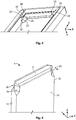
Fig. 2 and Fig. 3 each depict the touch-proof contact arrangement 1 in a schematic sectional view.Fig. 4 and Fig. 5 show acontact protection 5 or apin contact 4 of acontact arrangement 1 according to the invention in a schematic perspective view. - The touch-
proof contact arrangement 1 extends in a longitudinal direction X, a transverse direction Y and a vertical direction Z, which jointly span a Cartesian coordinate system. In the vertical direction Z, the touch-proof contact arrangement 1 can be plugged together with a mating contact (not shown) in a plug-in direction S. - The
contact arrangement 1 has an electrically insulatingcontact protection 5 and apin contact 4 in the form of a flat contact. At itssides 12 which delimit thepin contact 4 in the longitudinal direction X and at itsfree end 11 situated in the vertical direction Z, thepin contact 4 is covered by thecontact protection 5. Thesides 12 of thepin contact 4 are each covered by oneleg 8. Thefree end 11 is covered by a connectingsection 10 which connects thelegs 8. - The
pin contact 4 is equipped withcontact surfaces 14 which are arranged parallel to one another and which extend between thesides 12 along the vertical direction Z and longitudinal direction X, whereby these contact surfaces 14 can be contacted by a mating contact which is compatible with thepin contact 4. - The
contact protection 5 prevents a person from being able to unintentionally touch the electrically conductive contact points of thepin contact 4 with his/her finger. - In order also to prevent the
contact protection 5 from no longer covering thesides 12 when force is applied to thecontact protection 5 and/or thepin contact 4, thelegs 8 have awall thickness 15 transverse to thecontact surface 14 which is greater than the width of thepin contact 4 in the transverse direction Y. - It is necessary for the
contact arrangement 1 to have a high degree of mechanical stiffness, so that an elastic deformation of thecontact arrangement 1 is prevented if, for example, a bending force bears on thecontact protection 5 and exerts a bending force on thecontact arrangement 1. For this purpose, thesides 12, in theircorners 18 formed by thefree end 11 and therespective sides 12, are received in and/or pushed intolateral recesses 20 of thecontact protection 2. - The lateral recesses 20 are formed by
side walls 22 which protrude in the direction of theopposing leg 8 and which delimit the lateral recesses 20 in the transverse direction Y. Theside walls 22 are arranged incorners 24 formed by the connectingsection 10 and therespective leg 8. - The lateral recesses 20 have the shape of a substantially V-shaped groove, which is formed in a substantially complementary manner relative to a
cavity 26 at thesides 12 of thepin contact 4. Through the lateral recesses 20, there arises, with a compactly arranged touch-proof contact arrangement 1, ahigh overlap 28 between thecontact protection 5 and thepin contact 4. - The
contact arrangement 1 therefore has a form-fit in the direction transverse to thecontact surface 14 between thepin contact 4 and thecontact protection 5 in the form of a tongue-and-groove joint, in which the resilient means are formed by thecavity 26 at thesides 12 of thepin contact 4 and the groove of thelateral recess 20 of the contact protection. - The
pin contact 4 can be pushed in in plug-in direction S into thecontact protection 5, which has substantially a U-shaped cross-section. Here, thecavities 26 are pushed into and received in the respectivelateral recess 20. To guide and orientate thepin contact 4 during pushing-in, the lateral recesses 20 widen gradually in the longitudinal direction X at the end facing away from the connectingsection 10. In theguide 30 created as a result, thecavity 26 can be centered while being pushed-in the plug-in direction S and incorrect plugging is avoided. Theside walls 22 cover thepin contact 4 in the region of thecavities 26 transverse to thecontact surface 14, wherein theside wall 22outer surfaces 32 facing away from the lateral recesses 20 are aligned with thecontact surface 14. Theouter surfaces 32 can preferably be arranged flush with the contact surfaces 14. As a result, the mating contact is prevented from encountering resistance at an edge of theside walls 22, which runs transverse to the plug-in direction S, during plugging and/or unplugging and from being damaged as a result. - The
free end 11 of thepin contact 4 is arched in a convex manner and is received in a substantially complementaryconcave recess 34, which extends along the connectingsection 10 between sides of thelegs 8 which face one another. The convexly archedfree end 11 is formed by anobtuse bevel 38, which opens in a planarfront side 40 situated in a plane spanned by the longitudinal direction X and transverse direction Y. - Since the
pin contact 4 is received in the lateral recesses 20, and this already guarantees the necessary stiffness of thecontact arrangement 1, it is no longer necessary to have to push thefree end 11 into the connectingsection 10. Therefore, thepin contact 4 can ideally be pushed into therecess 34 of the connectingsection 10 snugly, or at least with a small spacing of less than 0.4 mm, in particular less than 0.2 mm, between thefree end 11 and the wall of therecess 34. Anedge 35 at the transition between thecontact surface 14 and the connectingsection 10 is thus prevented from protruding in thetransverse direction 4 from thecontact surface 14 on which the mating contact rubs during plugging and/or unplugging. According to this advantageous configuration, agap 36 between thecontact surface 14 and a of therecess 34 is negligibly small in the transverse direction Y at the transition in plug-in direction S from thepin contact 4 to the connectingsection 10, so that the mating contact is not damaged. - In contrast to already known touch-
proof contact arrangements 1, in which the form-fit between thepin contact 4 and thecontact protection 5 is formed at the connectingsection 10, thefree end 11 in the case of the touch-proof contact arrangement 1 according to the invention need not greatly overlap with the connectingsection 10. Thefree end 11 and therecess 34 can therefore be smaller in size in the vertical direction Z. In already known touch-proof contact arrangements 1, thefree end 11 tapers to an acute angle, so that thefree end 11 can dip deeply into therecess 34 of the connectingsection 10, and thus a stronger form-fit is created between thepin contact 4 and thecontact protection 5. The disadvantage here is, above all, that thegap 36 is larger and the mating contact is abraded at theedge 35 during plugging and/or unplugging. As a result, the number of possible plugging cycles is reduced and the wear of the plug connector and of the mating contact is greater. - The
outer surfaces 32 of theside walls 22 are arranged flush with the respectiveouter surfaces 36 of the connectingsection 10 facing away from therecess 34 in the transverse direction Y, and are aligned with the contact surfaces 14. As a result, no protruding edge comes into being at the transition between thepin contact 4 and thecontact protection 5 at which a mating contact can rub during plugging and/or unplugging. - Furthermore, the
side walls 22 complete a cross-section of the pin contact to make atotal cross-section 40, which corresponds in shape and size to the total cross-section 42 of thepin contact 4 in a region which is situated deeper in the vertical direction Z, and in which thepin contact 4 is arranged between the legs 48, but thesides 12 are not arranged in alateral recess 20. - Through the touch-
proof contact arrangement 1 according to the invention, it is thus possible to create a plug connector with a robust touch-proof contact arrangement 1, in which large bending forces can be withstood and wear of thecontact arrangement 1 and of the mating plug can be avoided. -
- 1
- contact arrangement
- 2
- plug connector
- 3
- housing
- 4
- pin contact
- 5
- contact protection
- 6
- slot opening
- 8
- leg
- 10
- connecting section
- 11
- free end
- 12
- side
- 13
- collar
- 14
- contact surface
- 15
- wall thickness
- 18
- corners of the pin contact
- 20
- lateral recesses
- 22
- side walls
- 24
- corners
- 26
- cavity
- 28
- overlap
- 30
- guide
- 32
- outer surface
- 34
- recess
- 35
- edge
- 36
- gap
- 38
- outer surface
- 40
- total cross-section
- 42
- total cross-section
- 48
- leg
- S
- plug-in direction
- X
- longitudinal direction
- Y
- transverse direction
- Z
- vertical direction
Claims (15)
- A touch-proof contact arrangement (1) for electrical plug connectors (2),with an electrical pin contact (4) that is covered at two sides (12) and at its free end (11) by an electrically insulating contact protection (5) with two legs (8) and a connecting section (10) connecting the two legs (8), andwhereby the two sides (12) of the pin contact (4) are received, at least in sections, in two lateral recesses (20) of the legs (8) of the contact protection (5).
- The touch-proof contact arrangement (1) according to Claim 1, wherein the free end (11) of the contact pin (4) is arched in a substantially convex manner and is received in a substantially concave recess (34) of the connecting section (10).
- The touch-proof contact arrangement (1) according to Claim 1 or 2, wherein the touch-proof contact arrangement (1) has a form-fit in a direction transverse to a contact surface (14) between the pin contact (4) and the contact protection (5), said contact surface (14) extending between the sides (12) of the pin contact (4).
- The touch-proof contact arrangement (1) according to any one of Claims 1 to 3, wherein the pin contact (4) has cavities (26) that are complementary to the lateral recesses (20).
- The touch-proof contact arrangement (1) according to Claim 4, wherein an at least one cavity (26) is arranged in a corner (18) of the pin contact (4) formed by the free end (11) and one side (12).
- The touch-proof contact arrangement (1) according to any one of Claims 1 to 5, wherein an inner width of the lateral recesses (20) increases at least in sections, transverse to the contact surface (14) in the direction away from the connecting section (10).
- The touch-proof contact arrangement (1) according to any one of Claims 1 to 6, wherein at least one lateral recess (20) is arranged between two side walls (22) of the legs (8), which side walls (22) protrude in the direction of the other leg (8).
- The touch-proof contact arrangement (1) according to Claim 7, wherein the side walls (20) projecting in the direction of the other leg are arranged in the corner (24) formed by the connecting section (10) and the respective leg (8).
- The touch-proof contact arrangement (1) according to Claim 7 or 8, wherein an outer surface (32) of the side wall (22), which faces away from the lateral recess (20) is aligned with the contact surface (14).
- The touch-proof contact arrangement (1) according to any one of Claims 7 to 9, wherein the side walls (22) are arranged substantially flush with the connecting section (10) at least in sections.
- The touch-proof contact arrangement according to any one of Claims 7 to 10, wherein an inner width between the outer surfaces (32) of the side walls (22) is smaller than a wall thickness (15) of the legs (8) transverse to the contact surface (14).
- The touch-proof contact arrangement (1) according to any one of Claims 7 to 11, wherein the side walls (22) complete a cross-section of the pin contact (4) to make a total cross-section which corresponds in shape and size to the total cross-section of the pin contact (4) in a region in which the pin contact (4) is arranged between the legs (8), but the sides (12) are not received in a lateral recess (20).
- The touch-proof contact arrangement (1) according to any one of Claims 7 to 12, wherein the side walls (22) cover the contact surface (14) at least in sections.
- An electrical plug connector (2) for a high-current and/or high-voltage plug, wherein the electrical plug connector has at least one touch-proof contact arrangement (1) according to any one of Claims 1 to 13.
- The electrical plug connector (2) according to Claim 14, wherein the plug connector has a housing which forms the contact protection (4) in one piece.
Applications Claiming Priority (1)
| Application Number | Priority Date | Filing Date | Title |
|---|---|---|---|
| DE102018211043.3A DE102018211043A1 (en) | 2018-07-04 | 2018-07-04 | Touch-protected contact arrangement |
Publications (2)
| Publication Number | Publication Date |
|---|---|
| EP3591768A1 true EP3591768A1 (en) | 2020-01-08 |
| EP3591768B1 EP3591768B1 (en) | 2022-05-11 |
Family
ID=67137873
Family Applications (1)
| Application Number | Title | Priority Date | Filing Date |
|---|---|---|---|
| EP19183706.1A Active EP3591768B1 (en) | 2018-07-04 | 2019-07-01 | Touch-proof contact arrangement |
Country Status (6)
| Country | Link |
|---|---|
| US (1) | US10855018B2 (en) |
| EP (1) | EP3591768B1 (en) |
| JP (1) | JP7353828B2 (en) |
| KR (1) | KR102735142B1 (en) |
| CN (1) | CN110690610B (en) |
| DE (1) | DE102018211043A1 (en) |
Cited By (1)
| Publication number | Priority date | Publication date | Assignee | Title |
|---|---|---|---|---|
| WO2022268571A1 (en) * | 2021-06-22 | 2022-12-29 | Kostal Kontakt Systeme Gmbh | Electrical contact element for an electrical connector, and electrical connector assembly having an electrical contact element |
Families Citing this family (14)
| Publication number | Priority date | Publication date | Assignee | Title |
|---|---|---|---|---|
| WO2018054685A1 (en) * | 2016-09-23 | 2018-03-29 | Stäubli Electrical Connectors Ag | Protected plug |
| JP6897623B2 (en) * | 2018-04-04 | 2021-06-30 | 株式会社オートネットワーク技術研究所 | connector |
| US11387589B2 (en) * | 2018-06-25 | 2022-07-12 | Autonetworks Technologies, Ltd. | Terminal |
| JP7056756B2 (en) * | 2018-11-16 | 2022-04-19 | 株式会社オートネットワーク技術研究所 | connector |
| JP2021132001A (en) * | 2020-02-21 | 2021-09-09 | 住友電装株式会社 | Connector and connector unit |
| JP7419869B2 (en) * | 2020-02-21 | 2024-01-23 | 住友電装株式会社 | Terminal unit and connector |
| JP7498433B2 (en) * | 2021-03-26 | 2024-06-12 | 株式会社オートネットワーク技術研究所 | Terminal with protective cap |
| DE102022002377A1 (en) | 2022-06-30 | 2024-01-04 | Kostal Kontakt Systeme Gmbh | Electrical connector part |
| KR20240114723A (en) * | 2023-01-17 | 2024-07-24 | 티이 커넥티비티 솔루션스 게엠베하 | High-voltage tab contact means with touch protection means and high-voltage connector |
| DE102023100974A1 (en) * | 2023-01-17 | 2024-07-18 | Te Connectivity Solutions Gmbh | High-voltage tab contact device with contact protection device and high-voltage connector |
| DE102023207183A1 (en) | 2023-07-27 | 2025-01-30 | Robert Bosch Gesellschaft mit beschränkter Haftung | High-current connector, power contact for a high-current connector and touch protection assembly |
| DE102023207182A1 (en) | 2023-07-27 | 2025-01-30 | Robert Bosch Gesellschaft mit beschränkter Haftung | High-current connector and power contact for a high-current connector and touch protection assembly |
| DE102023207181A1 (en) | 2023-07-27 | 2025-01-30 | Robert Bosch Gesellschaft mit beschränkter Haftung | High-current connector and power contact for a high-current connector and a touch protection assembly |
| DE102023207179A1 (en) | 2023-07-27 | 2025-01-30 | Robert Bosch Gesellschaft mit beschränkter Haftung | High-current connector and power contact for a high-current connector |
Citations (5)
| Publication number | Priority date | Publication date | Assignee | Title |
|---|---|---|---|---|
| JP2001266986A (en) * | 2000-03-24 | 2001-09-28 | Fujikura Ltd | Male terminal and connector and electrical connection structure using the same |
| US20110104916A1 (en) * | 2009-10-30 | 2011-05-05 | Square D Company | Plug-In Outlet (PIO) With Floating Fingerguard |
| EP2683036A1 (en) * | 2012-07-02 | 2014-01-08 | PHOENIX CONTACT GmbH & Co. KG | Connector housing for at least partially holding a plug-in housing component and electrical connector assembly for connecting a male contact element and a female contact element |
| WO2014187908A1 (en) * | 2013-05-24 | 2014-11-27 | Tyco Electronics Amp Gmbh | High-voltage finger protection |
| DE102015107304A1 (en) * | 2015-05-11 | 2016-11-17 | Wago Verwaltungsgesellschaft Mbh | Touch protection element and electrical connector |
Family Cites Families (19)
| Publication number | Priority date | Publication date | Assignee | Title |
|---|---|---|---|---|
| US3123424A (en) * | 1964-03-03 | Electrical plug with anti-shock prongs | ||
| US2537370A (en) * | 1948-10-12 | 1951-01-09 | Abraham D Parnes | Male safety plug member |
| US3781913A (en) * | 1972-06-08 | 1973-12-25 | F Liburdi | Electrical safety block |
| US4012103A (en) * | 1975-09-03 | 1977-03-15 | Medtronic, Inc. | Antishock, insulated connector |
| DE2637513A1 (en) * | 1976-08-20 | 1978-02-23 | Leybold Heraeus Gmbh & Co Kg | CONNECTOR ARRANGEMENT |
| GB2040605B (en) * | 1979-01-08 | 1983-03-09 | Bicc Ltd | Electric plugs |
| JPS58147180U (en) * | 1982-03-29 | 1983-10-03 | 富士通株式会社 | Electric shock prevention plug |
| US5391972A (en) * | 1988-03-11 | 1995-02-21 | Gardner; Billy J. | Cordless tool battery housing and charging system |
| DE4406879A1 (en) * | 1994-03-03 | 1995-09-07 | Bosch Gmbh Robert | Accumulator package for electrical hand machine tools |
| JP3670495B2 (en) * | 1998-11-09 | 2005-07-13 | 矢崎総業株式会社 | Terminal |
| JP2001035583A (en) * | 1999-05-20 | 2001-02-09 | Kawasaki Densen Kk | Power source plug |
| USD480362S1 (en) * | 2002-09-27 | 2003-10-07 | Jeff Yu | Plug cover |
| US7374460B1 (en) * | 2007-04-17 | 2008-05-20 | Traxxas Lp | Electrical connector assembly |
| JP5375440B2 (en) | 2009-08-26 | 2013-12-25 | 住友電装株式会社 | Male connector and connector device |
| CN201887194U (en) * | 2010-07-16 | 2011-06-29 | 富士康(昆山)电脑接插件有限公司 | Conducting terminal |
| CN202275984U (en) * | 2011-09-25 | 2012-06-13 | 王燕 | Anti-electric-shock plug |
| US8951051B2 (en) * | 2011-10-10 | 2015-02-10 | Lear Corporation | Connector having optimized tip |
| US8961202B2 (en) * | 2013-03-14 | 2015-02-24 | Robert P. Busson, JR. | Electrical safety device |
| CN206758705U (en) * | 2017-03-09 | 2017-12-15 | 四川职业技术学院 | A kind of electric shock resistant plug |
-
2018
- 2018-07-04 DE DE102018211043.3A patent/DE102018211043A1/en not_active Withdrawn
-
2019
- 2019-07-01 EP EP19183706.1A patent/EP3591768B1/en active Active
- 2019-07-01 JP JP2019122672A patent/JP7353828B2/en active Active
- 2019-07-02 CN CN201910588538.1A patent/CN110690610B/en active Active
- 2019-07-03 KR KR1020190080118A patent/KR102735142B1/en active Active
- 2019-07-03 US US16/502,366 patent/US10855018B2/en active Active
Patent Citations (5)
| Publication number | Priority date | Publication date | Assignee | Title |
|---|---|---|---|---|
| JP2001266986A (en) * | 2000-03-24 | 2001-09-28 | Fujikura Ltd | Male terminal and connector and electrical connection structure using the same |
| US20110104916A1 (en) * | 2009-10-30 | 2011-05-05 | Square D Company | Plug-In Outlet (PIO) With Floating Fingerguard |
| EP2683036A1 (en) * | 2012-07-02 | 2014-01-08 | PHOENIX CONTACT GmbH & Co. KG | Connector housing for at least partially holding a plug-in housing component and electrical connector assembly for connecting a male contact element and a female contact element |
| WO2014187908A1 (en) * | 2013-05-24 | 2014-11-27 | Tyco Electronics Amp Gmbh | High-voltage finger protection |
| DE102015107304A1 (en) * | 2015-05-11 | 2016-11-17 | Wago Verwaltungsgesellschaft Mbh | Touch protection element and electrical connector |
Cited By (1)
| Publication number | Priority date | Publication date | Assignee | Title |
|---|---|---|---|---|
| WO2022268571A1 (en) * | 2021-06-22 | 2022-12-29 | Kostal Kontakt Systeme Gmbh | Electrical contact element for an electrical connector, and electrical connector assembly having an electrical contact element |
Also Published As
| Publication number | Publication date |
|---|---|
| US10855018B2 (en) | 2020-12-01 |
| JP7353828B2 (en) | 2023-10-02 |
| DE102018211043A1 (en) | 2020-01-09 |
| KR102735142B1 (en) | 2024-11-26 |
| JP2020017522A (en) | 2020-01-30 |
| EP3591768B1 (en) | 2022-05-11 |
| CN110690610B (en) | 2022-12-27 |
| US20200014140A1 (en) | 2020-01-09 |
| KR20200004761A (en) | 2020-01-14 |
| CN110690610A (en) | 2020-01-14 |
Similar Documents
| Publication | Publication Date | Title |
|---|---|---|
| EP3591768B1 (en) | Touch-proof contact arrangement | |
| JP6336580B2 (en) | Connector element | |
| JP6422940B2 (en) | Connector assembly | |
| JP6961390B2 (en) | Connection cage connecting two electrical flat contacts | |
| US20190190197A1 (en) | Power connector and power connector device | |
| US10777932B2 (en) | Electric plug with elastic press-on elements | |
| US10608362B2 (en) | Relay terminal and relay connector | |
| US11158972B2 (en) | Socket connector assembly | |
| US10128605B2 (en) | Connector | |
| US10862236B2 (en) | Connector | |
| US20150295347A1 (en) | Connector and electronic device provided with same | |
| CN204130714U (en) | Terminal device | |
| US11050177B2 (en) | Contact assembly | |
| CN107181130B (en) | Connector and connector structure | |
| US9887495B2 (en) | Power connector | |
| US9166326B1 (en) | Electrical connector with contact guard | |
| CN102231461A (en) | An electrical connector comprising a guiding protrusion or pocket with a flexible fastening member | |
| EP2380243B1 (en) | Electrical connector assembly | |
| US8292675B2 (en) | Electrical connector having improved blocking member | |
| WO2012096407A1 (en) | Shield case of receptacle | |
| CN119948706A (en) | Contact inserts for plug connectors | |
| WO2015170529A1 (en) | Connector and connector assembly |
Legal Events
| Date | Code | Title | Description |
|---|---|---|---|
| PUAI | Public reference made under article 153(3) epc to a published international application that has entered the european phase |
Free format text: ORIGINAL CODE: 0009012 |
|
| STAA | Information on the status of an ep patent application or granted ep patent |
Free format text: STATUS: THE APPLICATION HAS BEEN PUBLISHED |
|
| AK | Designated contracting states |
Kind code of ref document: A1 Designated state(s): AL AT BE BG CH CY CZ DE DK EE ES FI FR GB GR HR HU IE IS IT LI LT LU LV MC MK MT NL NO PL PT RO RS SE SI SK SM TR |
|
| AX | Request for extension of the european patent |
Extension state: BA ME |
|
| STAA | Information on the status of an ep patent application or granted ep patent |
Free format text: STATUS: REQUEST FOR EXAMINATION WAS MADE |
|
| 17P | Request for examination filed |
Effective date: 20200325 |
|
| RBV | Designated contracting states (corrected) |
Designated state(s): AL AT BE BG CH CY CZ DE DK EE ES FI FR GB GR HR HU IE IS IT LI LT LU LV MC MK MT NL NO PL PT RO RS SE SI SK SM TR |
|
| STAA | Information on the status of an ep patent application or granted ep patent |
Free format text: STATUS: EXAMINATION IS IN PROGRESS |
|
| 17Q | First examination report despatched |
Effective date: 20210312 |
|
| GRAP | Despatch of communication of intention to grant a patent |
Free format text: ORIGINAL CODE: EPIDOSNIGR1 |
|
| STAA | Information on the status of an ep patent application or granted ep patent |
Free format text: STATUS: GRANT OF PATENT IS INTENDED |
|
| INTG | Intention to grant announced |
Effective date: 20220127 |
|
| GRAS | Grant fee paid |
Free format text: ORIGINAL CODE: EPIDOSNIGR3 |
|
| GRAA | (expected) grant |
Free format text: ORIGINAL CODE: 0009210 |
|
| STAA | Information on the status of an ep patent application or granted ep patent |
Free format text: STATUS: THE PATENT HAS BEEN GRANTED |
|
| AK | Designated contracting states |
Kind code of ref document: B1 Designated state(s): AL AT BE BG CH CY CZ DE DK EE ES FI FR GB GR HR HU IE IS IT LI LT LU LV MC MK MT NL NO PL PT RO RS SE SI SK SM TR |
|
| REG | Reference to a national code |
Ref country code: GB Ref legal event code: FG4D |
|
| REG | Reference to a national code |
Ref country code: CH Ref legal event code: EP |
|
| REG | Reference to a national code |
Ref country code: AT Ref legal event code: REF Ref document number: 1492261 Country of ref document: AT Kind code of ref document: T Effective date: 20220515 |
|
| REG | Reference to a national code |
Ref country code: DE Ref legal event code: R096 Ref document number: 602019014764 Country of ref document: DE |
|
| REG | Reference to a national code |
Ref country code: IE Ref legal event code: FG4D |
|
| REG | Reference to a national code |
Ref country code: LT Ref legal event code: MG9D |
|
| REG | Reference to a national code |
Ref country code: NL Ref legal event code: MP Effective date: 20220511 |
|
| REG | Reference to a national code |
Ref country code: AT Ref legal event code: MK05 Ref document number: 1492261 Country of ref document: AT Kind code of ref document: T Effective date: 20220511 |
|
| PG25 | Lapsed in a contracting state [announced via postgrant information from national office to epo] |
Ref country code: SE Free format text: LAPSE BECAUSE OF FAILURE TO SUBMIT A TRANSLATION OF THE DESCRIPTION OR TO PAY THE FEE WITHIN THE PRESCRIBED TIME-LIMIT Effective date: 20220511 Ref country code: PT Free format text: LAPSE BECAUSE OF FAILURE TO SUBMIT A TRANSLATION OF THE DESCRIPTION OR TO PAY THE FEE WITHIN THE PRESCRIBED TIME-LIMIT Effective date: 20220912 Ref country code: NO Free format text: LAPSE BECAUSE OF FAILURE TO SUBMIT A TRANSLATION OF THE DESCRIPTION OR TO PAY THE FEE WITHIN THE PRESCRIBED TIME-LIMIT Effective date: 20220811 Ref country code: NL Free format text: LAPSE BECAUSE OF FAILURE TO SUBMIT A TRANSLATION OF THE DESCRIPTION OR TO PAY THE FEE WITHIN THE PRESCRIBED TIME-LIMIT Effective date: 20220511 Ref country code: LT Free format text: LAPSE BECAUSE OF FAILURE TO SUBMIT A TRANSLATION OF THE DESCRIPTION OR TO PAY THE FEE WITHIN THE PRESCRIBED TIME-LIMIT Effective date: 20220511 Ref country code: HR Free format text: LAPSE BECAUSE OF FAILURE TO SUBMIT A TRANSLATION OF THE DESCRIPTION OR TO PAY THE FEE WITHIN THE PRESCRIBED TIME-LIMIT Effective date: 20220511 Ref country code: GR Free format text: LAPSE BECAUSE OF FAILURE TO SUBMIT A TRANSLATION OF THE DESCRIPTION OR TO PAY THE FEE WITHIN THE PRESCRIBED TIME-LIMIT Effective date: 20220812 Ref country code: FI Free format text: LAPSE BECAUSE OF FAILURE TO SUBMIT A TRANSLATION OF THE DESCRIPTION OR TO PAY THE FEE WITHIN THE PRESCRIBED TIME-LIMIT Effective date: 20220511 Ref country code: ES Free format text: LAPSE BECAUSE OF FAILURE TO SUBMIT A TRANSLATION OF THE DESCRIPTION OR TO PAY THE FEE WITHIN THE PRESCRIBED TIME-LIMIT Effective date: 20220511 Ref country code: BG Free format text: LAPSE BECAUSE OF FAILURE TO SUBMIT A TRANSLATION OF THE DESCRIPTION OR TO PAY THE FEE WITHIN THE PRESCRIBED TIME-LIMIT Effective date: 20220811 Ref country code: AT Free format text: LAPSE BECAUSE OF FAILURE TO SUBMIT A TRANSLATION OF THE DESCRIPTION OR TO PAY THE FEE WITHIN THE PRESCRIBED TIME-LIMIT Effective date: 20220511 |
|
| PG25 | Lapsed in a contracting state [announced via postgrant information from national office to epo] |
Ref country code: RS Free format text: LAPSE BECAUSE OF FAILURE TO SUBMIT A TRANSLATION OF THE DESCRIPTION OR TO PAY THE FEE WITHIN THE PRESCRIBED TIME-LIMIT Effective date: 20220511 Ref country code: PL Free format text: LAPSE BECAUSE OF FAILURE TO SUBMIT A TRANSLATION OF THE DESCRIPTION OR TO PAY THE FEE WITHIN THE PRESCRIBED TIME-LIMIT Effective date: 20220511 Ref country code: LV Free format text: LAPSE BECAUSE OF FAILURE TO SUBMIT A TRANSLATION OF THE DESCRIPTION OR TO PAY THE FEE WITHIN THE PRESCRIBED TIME-LIMIT Effective date: 20220511 Ref country code: IS Free format text: LAPSE BECAUSE OF FAILURE TO SUBMIT A TRANSLATION OF THE DESCRIPTION OR TO PAY THE FEE WITHIN THE PRESCRIBED TIME-LIMIT Effective date: 20220911 |
|
| PG25 | Lapsed in a contracting state [announced via postgrant information from national office to epo] |
Ref country code: SM Free format text: LAPSE BECAUSE OF FAILURE TO SUBMIT A TRANSLATION OF THE DESCRIPTION OR TO PAY THE FEE WITHIN THE PRESCRIBED TIME-LIMIT Effective date: 20220511 Ref country code: SK Free format text: LAPSE BECAUSE OF FAILURE TO SUBMIT A TRANSLATION OF THE DESCRIPTION OR TO PAY THE FEE WITHIN THE PRESCRIBED TIME-LIMIT Effective date: 20220511 Ref country code: RO Free format text: LAPSE BECAUSE OF FAILURE TO SUBMIT A TRANSLATION OF THE DESCRIPTION OR TO PAY THE FEE WITHIN THE PRESCRIBED TIME-LIMIT Effective date: 20220511 Ref country code: EE Free format text: LAPSE BECAUSE OF FAILURE TO SUBMIT A TRANSLATION OF THE DESCRIPTION OR TO PAY THE FEE WITHIN THE PRESCRIBED TIME-LIMIT Effective date: 20220511 Ref country code: DK Free format text: LAPSE BECAUSE OF FAILURE TO SUBMIT A TRANSLATION OF THE DESCRIPTION OR TO PAY THE FEE WITHIN THE PRESCRIBED TIME-LIMIT Effective date: 20220511 Ref country code: CZ Free format text: LAPSE BECAUSE OF FAILURE TO SUBMIT A TRANSLATION OF THE DESCRIPTION OR TO PAY THE FEE WITHIN THE PRESCRIBED TIME-LIMIT Effective date: 20220511 |
|
| REG | Reference to a national code |
Ref country code: DE Ref legal event code: R097 Ref document number: 602019014764 Country of ref document: DE |
|
| PG25 | Lapsed in a contracting state [announced via postgrant information from national office to epo] |
Ref country code: MC Free format text: LAPSE BECAUSE OF FAILURE TO SUBMIT A TRANSLATION OF THE DESCRIPTION OR TO PAY THE FEE WITHIN THE PRESCRIBED TIME-LIMIT Effective date: 20220511 |
|
| REG | Reference to a national code |
Ref country code: CH Ref legal event code: PL |
|
| PLBE | No opposition filed within time limit |
Free format text: ORIGINAL CODE: 0009261 |
|
| STAA | Information on the status of an ep patent application or granted ep patent |
Free format text: STATUS: NO OPPOSITION FILED WITHIN TIME LIMIT |
|
| REG | Reference to a national code |
Ref country code: BE Ref legal event code: MM Effective date: 20220731 |
|
| PG25 | Lapsed in a contracting state [announced via postgrant information from national office to epo] |
Ref country code: AL Free format text: LAPSE BECAUSE OF FAILURE TO SUBMIT A TRANSLATION OF THE DESCRIPTION OR TO PAY THE FEE WITHIN THE PRESCRIBED TIME-LIMIT Effective date: 20220511 |
|
| 26N | No opposition filed |
Effective date: 20230214 |
|
| PG25 | Lapsed in a contracting state [announced via postgrant information from national office to epo] |
Ref country code: LU Free format text: LAPSE BECAUSE OF NON-PAYMENT OF DUE FEES Effective date: 20220701 Ref country code: LI Free format text: LAPSE BECAUSE OF NON-PAYMENT OF DUE FEES Effective date: 20220731 Ref country code: CH Free format text: LAPSE BECAUSE OF NON-PAYMENT OF DUE FEES Effective date: 20220731 |
|
| PG25 | Lapsed in a contracting state [announced via postgrant information from national office to epo] |
Ref country code: SI Free format text: LAPSE BECAUSE OF FAILURE TO SUBMIT A TRANSLATION OF THE DESCRIPTION OR TO PAY THE FEE WITHIN THE PRESCRIBED TIME-LIMIT Effective date: 20220511 Ref country code: BE Free format text: LAPSE BECAUSE OF NON-PAYMENT OF DUE FEES Effective date: 20220731 |
|
| PG25 | Lapsed in a contracting state [announced via postgrant information from national office to epo] |
Ref country code: IE Free format text: LAPSE BECAUSE OF NON-PAYMENT OF DUE FEES Effective date: 20220701 |
|
| GBPC | Gb: european patent ceased through non-payment of renewal fee |
Effective date: 20230701 |
|
| PG25 | Lapsed in a contracting state [announced via postgrant information from national office to epo] |
Ref country code: HU Free format text: LAPSE BECAUSE OF FAILURE TO SUBMIT A TRANSLATION OF THE DESCRIPTION OR TO PAY THE FEE WITHIN THE PRESCRIBED TIME-LIMIT; INVALID AB INITIO Effective date: 20190701 |
|
| PG25 | Lapsed in a contracting state [announced via postgrant information from national office to epo] |
Ref country code: MK Free format text: LAPSE BECAUSE OF FAILURE TO SUBMIT A TRANSLATION OF THE DESCRIPTION OR TO PAY THE FEE WITHIN THE PRESCRIBED TIME-LIMIT Effective date: 20220511 Ref country code: CY Free format text: LAPSE BECAUSE OF FAILURE TO SUBMIT A TRANSLATION OF THE DESCRIPTION OR TO PAY THE FEE WITHIN THE PRESCRIBED TIME-LIMIT Effective date: 20220511 Ref country code: GB Free format text: LAPSE BECAUSE OF NON-PAYMENT OF DUE FEES Effective date: 20230701 |
|
| PG25 | Lapsed in a contracting state [announced via postgrant information from national office to epo] |
Ref country code: MT Free format text: LAPSE BECAUSE OF FAILURE TO SUBMIT A TRANSLATION OF THE DESCRIPTION OR TO PAY THE FEE WITHIN THE PRESCRIBED TIME-LIMIT Effective date: 20220511 |
|
| PG25 | Lapsed in a contracting state [announced via postgrant information from national office to epo] |
Ref country code: BG Free format text: LAPSE BECAUSE OF FAILURE TO SUBMIT A TRANSLATION OF THE DESCRIPTION OR TO PAY THE FEE WITHIN THE PRESCRIBED TIME-LIMIT Effective date: 20220511 |
|
| PG25 | Lapsed in a contracting state [announced via postgrant information from national office to epo] |
Ref country code: BG Free format text: LAPSE BECAUSE OF FAILURE TO SUBMIT A TRANSLATION OF THE DESCRIPTION OR TO PAY THE FEE WITHIN THE PRESCRIBED TIME-LIMIT Effective date: 20220511 |
|
| PGFP | Annual fee paid to national office [announced via postgrant information from national office to epo] |
Ref country code: FR Payment date: 20250610 Year of fee payment: 7 |
|
| PGFP | Annual fee paid to national office [announced via postgrant information from national office to epo] |
Ref country code: DE Payment date: 20250604 Year of fee payment: 7 |
|
| PGFP | Annual fee paid to national office [announced via postgrant information from national office to epo] |
Ref country code: IT Payment date: 20250623 Year of fee payment: 7 |
|
| PG25 | Lapsed in a contracting state [announced via postgrant information from national office to epo] |
Ref country code: TR Free format text: LAPSE BECAUSE OF FAILURE TO SUBMIT A TRANSLATION OF THE DESCRIPTION OR TO PAY THE FEE WITHIN THE PRESCRIBED TIME-LIMIT Effective date: 20220511 |