EP3591740A1 - Battery pack - Google Patents
Battery pack Download PDFInfo
- Publication number
- EP3591740A1 EP3591740A1 EP19183365.6A EP19183365A EP3591740A1 EP 3591740 A1 EP3591740 A1 EP 3591740A1 EP 19183365 A EP19183365 A EP 19183365A EP 3591740 A1 EP3591740 A1 EP 3591740A1
- Authority
- EP
- European Patent Office
- Prior art keywords
- batteries
- electrode tabs
- multiple batteries
- busbars
- busbar modules
- Prior art date
- Legal status (The legal status is an assumption and is not a legal conclusion. Google has not performed a legal analysis and makes no representation as to the accuracy of the status listed.)
- Pending
Links
Images

Classifications
-
- H—ELECTRICITY
- H01—ELECTRIC ELEMENTS
- H01M—PROCESSES OR MEANS, e.g. BATTERIES, FOR THE DIRECT CONVERSION OF CHEMICAL ENERGY INTO ELECTRICAL ENERGY
- H01M50/00—Constructional details or processes of manufacture of the non-active parts of electrochemical cells other than fuel cells, e.g. hybrid cells
- H01M50/10—Primary casings; Jackets or wrappings
- H01M50/147—Lids or covers
- H01M50/148—Lids or covers characterised by their shape
- H01M50/15—Lids or covers characterised by their shape for prismatic or rectangular cells
-
- H—ELECTRICITY
- H01—ELECTRIC ELEMENTS
- H01M—PROCESSES OR MEANS, e.g. BATTERIES, FOR THE DIRECT CONVERSION OF CHEMICAL ENERGY INTO ELECTRICAL ENERGY
- H01M10/00—Secondary cells; Manufacture thereof
- H01M10/60—Heating or cooling; Temperature control
- H01M10/61—Types of temperature control
- H01M10/613—Cooling or keeping cold
-
- H—ELECTRICITY
- H01—ELECTRIC ELEMENTS
- H01M—PROCESSES OR MEANS, e.g. BATTERIES, FOR THE DIRECT CONVERSION OF CHEMICAL ENERGY INTO ELECTRICAL ENERGY
- H01M10/00—Secondary cells; Manufacture thereof
- H01M10/04—Construction or manufacture in general
- H01M10/0413—Large-sized flat cells or batteries for motive or stationary systems with plate-like electrodes
-
- H—ELECTRICITY
- H01—ELECTRIC ELEMENTS
- H01M—PROCESSES OR MEANS, e.g. BATTERIES, FOR THE DIRECT CONVERSION OF CHEMICAL ENERGY INTO ELECTRICAL ENERGY
- H01M10/00—Secondary cells; Manufacture thereof
- H01M10/05—Accumulators with non-aqueous electrolyte
- H01M10/058—Construction or manufacture
- H01M10/0585—Construction or manufacture of accumulators having only flat construction elements, i.e. flat positive electrodes, flat negative electrodes and flat separators
-
- H—ELECTRICITY
- H01—ELECTRIC ELEMENTS
- H01M—PROCESSES OR MEANS, e.g. BATTERIES, FOR THE DIRECT CONVERSION OF CHEMICAL ENERGY INTO ELECTRICAL ENERGY
- H01M10/00—Secondary cells; Manufacture thereof
- H01M10/60—Heating or cooling; Temperature control
- H01M10/64—Heating or cooling; Temperature control characterised by the shape of the cells
- H01M10/647—Prismatic or flat cells, e.g. pouch cells
-
- H—ELECTRICITY
- H01—ELECTRIC ELEMENTS
- H01M—PROCESSES OR MEANS, e.g. BATTERIES, FOR THE DIRECT CONVERSION OF CHEMICAL ENERGY INTO ELECTRICAL ENERGY
- H01M50/00—Constructional details or processes of manufacture of the non-active parts of electrochemical cells other than fuel cells, e.g. hybrid cells
- H01M50/20—Mountings; Secondary casings or frames; Racks, modules or packs; Suspension devices; Shock absorbers; Transport or carrying devices; Holders
- H01M50/204—Racks, modules or packs for multiple batteries or multiple cells
- H01M50/207—Racks, modules or packs for multiple batteries or multiple cells characterised by their shape
- H01M50/211—Racks, modules or packs for multiple batteries or multiple cells characterised by their shape adapted for pouch cells
-
- H—ELECTRICITY
- H01—ELECTRIC ELEMENTS
- H01M—PROCESSES OR MEANS, e.g. BATTERIES, FOR THE DIRECT CONVERSION OF CHEMICAL ENERGY INTO ELECTRICAL ENERGY
- H01M50/00—Constructional details or processes of manufacture of the non-active parts of electrochemical cells other than fuel cells, e.g. hybrid cells
- H01M50/20—Mountings; Secondary casings or frames; Racks, modules or packs; Suspension devices; Shock absorbers; Transport or carrying devices; Holders
- H01M50/289—Mountings; Secondary casings or frames; Racks, modules or packs; Suspension devices; Shock absorbers; Transport or carrying devices; Holders characterised by spacing elements or positioning means within frames, racks or packs
- H01M50/291—Mountings; Secondary casings or frames; Racks, modules or packs; Suspension devices; Shock absorbers; Transport or carrying devices; Holders characterised by spacing elements or positioning means within frames, racks or packs characterised by their shape
-
- H—ELECTRICITY
- H01—ELECTRIC ELEMENTS
- H01M—PROCESSES OR MEANS, e.g. BATTERIES, FOR THE DIRECT CONVERSION OF CHEMICAL ENERGY INTO ELECTRICAL ENERGY
- H01M50/00—Constructional details or processes of manufacture of the non-active parts of electrochemical cells other than fuel cells, e.g. hybrid cells
- H01M50/20—Mountings; Secondary casings or frames; Racks, modules or packs; Suspension devices; Shock absorbers; Transport or carrying devices; Holders
- H01M50/289—Mountings; Secondary casings or frames; Racks, modules or packs; Suspension devices; Shock absorbers; Transport or carrying devices; Holders characterised by spacing elements or positioning means within frames, racks or packs
- H01M50/293—Mountings; Secondary casings or frames; Racks, modules or packs; Suspension devices; Shock absorbers; Transport or carrying devices; Holders characterised by spacing elements or positioning means within frames, racks or packs characterised by the material
-
- H—ELECTRICITY
- H01—ELECTRIC ELEMENTS
- H01M—PROCESSES OR MEANS, e.g. BATTERIES, FOR THE DIRECT CONVERSION OF CHEMICAL ENERGY INTO ELECTRICAL ENERGY
- H01M50/00—Constructional details or processes of manufacture of the non-active parts of electrochemical cells other than fuel cells, e.g. hybrid cells
- H01M50/50—Current conducting connections for cells or batteries
- H01M50/502—Interconnectors for connecting terminals of adjacent batteries; Interconnectors for connecting cells outside a battery casing
- H01M50/503—Interconnectors for connecting terminals of adjacent batteries; Interconnectors for connecting cells outside a battery casing characterised by the shape of the interconnectors
-
- H—ELECTRICITY
- H01—ELECTRIC ELEMENTS
- H01M—PROCESSES OR MEANS, e.g. BATTERIES, FOR THE DIRECT CONVERSION OF CHEMICAL ENERGY INTO ELECTRICAL ENERGY
- H01M2220/00—Batteries for particular applications
- H01M2220/20—Batteries in motive systems, e.g. vehicle, ship, plane
-
- Y—GENERAL TAGGING OF NEW TECHNOLOGICAL DEVELOPMENTS; GENERAL TAGGING OF CROSS-SECTIONAL TECHNOLOGIES SPANNING OVER SEVERAL SECTIONS OF THE IPC; TECHNICAL SUBJECTS COVERED BY FORMER USPC CROSS-REFERENCE ART COLLECTIONS [XRACs] AND DIGESTS
- Y02—TECHNOLOGIES OR APPLICATIONS FOR MITIGATION OR ADAPTATION AGAINST CLIMATE CHANGE
- Y02E—REDUCTION OF GREENHOUSE GAS [GHG] EMISSIONS, RELATED TO ENERGY GENERATION, TRANSMISSION OR DISTRIBUTION
- Y02E60/00—Enabling technologies; Technologies with a potential or indirect contribution to GHG emissions mitigation
- Y02E60/10—Energy storage using batteries
-
- Y—GENERAL TAGGING OF NEW TECHNOLOGICAL DEVELOPMENTS; GENERAL TAGGING OF CROSS-SECTIONAL TECHNOLOGIES SPANNING OVER SEVERAL SECTIONS OF THE IPC; TECHNICAL SUBJECTS COVERED BY FORMER USPC CROSS-REFERENCE ART COLLECTIONS [XRACs] AND DIGESTS
- Y02—TECHNOLOGIES OR APPLICATIONS FOR MITIGATION OR ADAPTATION AGAINST CLIMATE CHANGE
- Y02P—CLIMATE CHANGE MITIGATION TECHNOLOGIES IN THE PRODUCTION OR PROCESSING OF GOODS
- Y02P70/00—Climate change mitigation technologies in the production process for final industrial or consumer products
- Y02P70/50—Manufacturing or production processes characterised by the final manufactured product
Definitions
- the present invention relates to a battery pack.
- the above mentioned battery module 10 includes, as shown in Fig.4 , multiple batteries 111-116 stacked on each other, end plates 121, 122 arranged above and below the multiple batteries 111-116 and busbar modules 131, 132 for connecting the multiple batteries 111-116 in series.
- Electrode tabs 171 protrude from ends of the batteries 111-116.
- busbar modules 131, 132 multiple busbars 133 and slits arranged above and below the busbars 133 (not shown) are provided.
- the multiple batteries 111-116 are connected in series by inserting the electrode tabs 171 into the slits of these busbar modules 131, 132 and jointing the electrode tabs 171 with the busbars 133.
- the above mentioned busbar modules 131, 132 are, as shown in the leftmost and middle parts of Fig.4 , fastened and fixed to the end plates 121, 122 arranged above and below the batteries 111-116.
- the above mentioned batteries 111-116 expands and contracts with charging and discharging.
- the busbar modules 131, 132 are deformed with such expansion or contraction, which causes a load on the electrode tabs 171 wherein a fatigue fracture of the electrode tab 171 and/or separation of the joint may occur by repeatedly applying stress.
- the busbar modules 131, 132 may be also damaged by their deforming.
- Patent Literature 1 JP 2013-229266 A1
- the present invention is provided in view of the above background and aimed at providing a battery pack which enables a reduction of load on the electrodes caused by expansion and/or contraction of the batteries.
- a battery pack is characterized in that it includes multiple batteries with electrodes protruding from both respective ends, a substrate with insertion holes formed therein, and a fixing plate arranged between two of the multiple batteries which are adjacent to each other, wherein the multiple batteries are stacked in a direction orthogonal to a protrusion direction of the electrodes, wherein the electrodes protruding from the both respective ends of the multiple batteries are inserted into the insertion holes, and wherein the fixing plate and the substrate are fixed to each other.
- the fixing plate may be formed from aluminum.
- the fixing plate may be arranged between two of the multiple batteries which are adjacent to a center.
- a battery module 1 includes multiple stacked batteries 21-26, a pair of end plates 31, 32 positioned on both sides in a stacking direction D1 of the multiple batteries 21-26, a pair of busbar modules 41, 42 for connecting the multiple batteries 21-26 in series, and one aluminum plate 5 (fixing plate).
- Each of the multiple batteries 21-26 is formed e.g. from a laminated battery which consists of a lithium secondary battery, wherein it is a flat battery with a small thickness in the stacking direction D1.
- the multiple batteries 21-26 include battery bodies 201 which are rectangular when seen from one side in the stacking direction D1, and pairs of ribbon-shaped electrode tabs 202, 202 (electrodes). The pairs of electrode tabs 202, 202 protrude from the respective centers of both ends of the battery bodies 201 which form their short sides. As a result, a protrusion direction D2 of the electrode tabs 202, 202 is orthogonal to the stacking direction D1.
- one of the pair of electrode tabs 202, 202 described above forms a positive electrode of a battery 21-26 while the other forms a negative electrode of the battery 21-26.
- the multiple batteries 21-26 are stacked in alternating orientations so that the electrode tabs 202 forming positive electrodes are alternating with the electrode tabs 202 forming negative electrodes. Additionally, the multiple batteries 21-26 are connected in series by using busbars 402 as described below to connect the electrode tabs 202 forming positive electrodes to the electrode tabs 202 forming negative electrodes which are adjacent.
- the pair of end plates 31, 32 is rectangular plate-like elements made of hard plastic or metallic material (iron, aluminum, stainless steel etc.) and arranged on both sides of the multiple batteries 21-26 in the stacking direction D1. As a consequence, the multiple batteries 21-26 are arranged with their both sides in the stacking direction D1 disposed between this pair of end plates 31, 32. Furthermore, the pair of end plates 31, 32 is arranged vertically to the stacking direction D1.
- the pair of busbar modules 41, 42 is each formed in a plate-shape and arranged on both sides of the multiple batteries 21-26 in the protrusion direction D2. As a consequence, the multiple batteries 21-26 are arranged with their both sides in the protrusion direction D2 disposed between this pair of busbar modules 41, 42. Furthermore, the pair of busbar modules 41, 42 is arranged vertically to the protrusion direction D2.
- the pair of busbar modules 41, 42 each includes a substrate 401 and busbars 402 supported thereon.
- the substrates 401 consist of plastic etc. and are formed in a rectangular shape when seen in the protrusion direction D2.
- the busbars 402 consist of metallic material such as copper or brass etc. and the electrode tabs 202 are jointed using welding or soldering etc. Said busbars 402 are exposed and supported on outer surfaces of the substrates 401, i.e. on their surfaces opposed to the batteries 21-26. While according to the present embodiment, the busbars 402 are molded in one-pieces during producing the substrates 401, it may be also provided that the busbars 402 are attached with any means after producing the substrates 401.
- busbars 402 are formed in a linear shape which is elongate along a orthogonal direction D3 orthogonal to the stacking direction D1 as well as the protrusion direction D2, wherein a plurality of the busbars 402 are arranged adjacent to each other in the stacking direction D1.
- the number of the busbars 402 corresponds to that of combinations of positive and negative electrode tabs 202 which should be connected to each other.
- three busbars 402 are provided in a busbar module 41 on the one side in the protrusion direction D2 (the left side in Fig.2 ) while two busbars 402 are provided in a busbar module 42 on the other side in the protrusion direction D2 (the right side in Fig.2 ).
- slits SL as six insertion holes for inserting said electrode tabs 202 therethrough are formed in the substrates 401, arranged adjacent to each other in the stacking direction D1.
- the slits SL are formed in a linear form which is elongate along the orthogonal direction D3.
- the six slits SL are formed along both end edges of the three busbars 402 in the stacking direction D1.
- the busbar module 42 In the busbar module 42, four middle slits SL are formed along both end edges of two busbars 402 in the stacking direction D1.
- the electrode tabs 202 inserted into the four respective central slits SL in the busbar module 42 protrude over the both end edges of the busbars 402 in the stacking direction D1, wherein the electrode tabs 202 are jointed to the busbars 402 after being bent along surfaces of the busbars 402.
- the electrode tabs 202 inserted into two respective slits SL on both ends in the busbar module 42 protrude over the substrate 401 and form electrodes of the battery module 1.
- a groove G is formed nearly at a center of the substrate 401 in the stacking direction D1 for inserting both ends of an aluminum plate 5 as described below into the groove G.
- the groove G is formed along the orthogonal direction D3.
- the aluminum plate 5 is configured in a plate-shape with an essentially same size and a same thickness as the battery body 201.
- the aluminum plate 5 is arranged between two batteries 23, 24 which are adjacent to a center of the multiple batteries 21-26.
- the aluminum plate 5 is fixed in the stacking direction D1 to the batteries 21-26 by being sandwiched between the two batteries 23, 24.
- both ends of the aluminum plate 5 in the protrusion direction D2 are fitted into the grooves G of the busbar modules 41, 42.
- the aluminum plate 5 and the busbar modules 41, 42 are fixed.
- the busbar modules 41, 42 are not fixed to the end plates 31, 32.
- the wording "two of the multiple batteries 21-26 which are adjacent to a center” means two batteries 23, 24 where the number of batteries 21-23 on the one side of the aluminum plate 5 in the stacking direction D1 (upper side in Fig.2 ) is equal to that of batteries 24-26 on the other side (lower side in Fig.2 ) if the number of the multiple batteries 21-26 is six (i.e. an even number) as shown in the present embodiment.
- the aluminum plate 5 is arranged between two batteries 23, 24 of the multiple batteries 21-26 which are adjacent to the center, wherein the aluminum plate 5 and the busbar modules 41 and 42 are fixed.
- the busbar modules 41, 42 are fixed, no load may be applied on the electrode tabs 202, as the busbar modules 41, 42 move together with the batteries 21-26 even in case of oscillation of a vehicle.
- the busbar modules 41, 42 are not fixed to the end plates 31, 32, the busbar modules 41, 42 may not be deformed even in case that the batteries 21-26 expand or contract and their size in the stacking direction D1 varies.
- a position offset of the electrode tabs 202 of batteries 21, 26 on both ends in the stacking direction D1 from the slits SL of the busbar modules 41, 42 will be half, i.e. 2mm, so that a load on the electrode tabs 202 can be reduced which is accompanied by expansion or contraction of the batteries 21-26.
- the aluminum plate 5 made of aluminum was used as the fixing plate. This can obtain a cooling effect of the batteries 21-26.
- the aluminum plate 5 according to the above described embodiment is arranged between two batteries 23, 24 of the multiple batteries 21-26 which are adjacent to the center. This does not enable only the position offset to be half as described above, but also more cooling effect by inserting the aluminum plate 5 into the center with a higher temperature.
- the fixing plate according to the above described embodiment consists of the aluminum plate 5, it is not limited thereto.
- the fixing plate any element is possible which can be arranged between two batteries 23, 24 to fix busbar modules 41, 42, and it may be also formed from plastic etc.
- the aluminum plate 5 is arranged between two batteries 23, 24 of the multiple batteries 21-26 which are adjacent to the center, the present invention is not limited to this.
- the aluminum plate 5 it is only required that it is arranged between any two of the multiple batteries 21-26 which are adjacent to each other, it may also be arranged for example between the batteries 21 and 22.
- a position offset of an electrode tab 202 at one end of the battery 21 in the stacking direction D1 from the slit SL of the busbar module 41, 42 will be smaller than 4mm, a load on the electrode tab 202 can be reduced.
- busbar modules 41, 42 are not fixed to the end plates 31, 32, the present invention is not limited to this. If the substrates 401 of the busbar modules 41, 42 consist of elastic elements such as rubber to provide a contracting function, the busbar modules 41, 42 may also be fastened to the end plates 31, 32.
- the aluminum plate 5 according to the above described embodiment was fitted into the grooves G of the busbar modules 41, 42 to be fixed so that it may not be moved in the stacking direction D1
- the present invention is not limited to this. It is also possible that tabs to be arranged above or below the busbar modules 41, 42 are provided at the aluminum plate 5 and fixed by fastening with screws.
- the busbars 402 supported on the substrates 401 were used to connect the electrode tabs 202 of the batteries 21-26
- the present invention is not limited to this. According to the present invention, only substrates 401 into which the electrode tabs 202 are to be inserted may be needed in order to connect the multiple batteries 21-26 in series by connecting the electrode tabs 202 of the batteries 21-26 to each other which are adjacent to each other, and for example, the electrode tabs 202 may be welded with each other without busbars 402, as shown in Fig.3 .
Landscapes
- Chemical & Material Sciences (AREA)
- Chemical Kinetics & Catalysis (AREA)
- Electrochemistry (AREA)
- General Chemical & Material Sciences (AREA)
- Engineering & Computer Science (AREA)
- Manufacturing & Machinery (AREA)
- Connection Of Batteries Or Terminals (AREA)
- Battery Mounting, Suspending (AREA)
- Secondary Cells (AREA)
Abstract
Description
- The present invention relates to a battery pack.
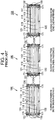
- As the above mentioned battery pack, a battery module according to Patent Literature 1 is proposed. The above mentioned battery module 10 includes, as shown in
Fig.4 , multiple batteries 111-116 stacked on each other,end plates busbar modules 131, 132 for connecting the multiple batteries 111-116 in series. -
Electrode tabs 171 protrude from ends of the batteries 111-116. With regard to thebusbar modules 131, 132,multiple busbars 133 and slits arranged above and below the busbars 133 (not shown) are provided. The multiple batteries 111-116 are connected in series by inserting theelectrode tabs 171 into the slits of thesebusbar modules 131, 132 and jointing theelectrode tabs 171 with thebusbars 133. The above mentionedbusbar modules 131, 132 are, as shown in the leftmost and middle parts ofFig.4 , fastened and fixed to theend plates - The above mentioned batteries 111-116 expands and contracts with charging and discharging. There has been the problem that the
busbar modules 131, 132 are deformed with such expansion or contraction, which causes a load on theelectrode tabs 171 wherein a fatigue fracture of theelectrode tab 171 and/or separation of the joint may occur by repeatedly applying stress. There has been also the risk that thebusbar modules 131, 132 may be also damaged by their deforming. - Therefore, as shown in the rightmost part of
Fig.4 , it would be conceivable to fasten thebusbar module 131, 132 on only one of theend plates busbar modules 131, 132. However, even in this case, a large position offset may occur with the expansion or contraction between theelectrode tabs 171 of thebatteries 111 on the side which is not fastened (top side in the figure) and slits of thebusbar modules 131, 132. In more details, under the assumption that for example a variation of ± 2 mm occurs at the multiple batteries 111-116 as a whole with expansion or contraction, a position offset of maximal 4 mm will occur between theelectrode tabs 171 of thebatteries 111 on the side which is not fastened and the slits of thebusbar modules 131, 132. Therefore, there is the problem that this results in a load on theelectrode tabs 171, which causes a fatigue fracture of theelectrode tab 171 and/or separation of the joint may occur by repeatedly applying stress. - Patent Literature 1:
JP 2013-229266 A1 - The present invention is provided in view of the above background and aimed at providing a battery pack which enables a reduction of load on the electrodes caused by expansion and/or contraction of the batteries.
- A battery pack according to embodiments of the present invention is characterized in that it includes multiple batteries with electrodes protruding from both respective ends, a substrate with insertion holes formed therein, and a fixing plate arranged between two of the multiple batteries which are adjacent to each other, wherein the multiple batteries are stacked in a direction orthogonal to a protrusion direction of the electrodes, wherein the electrodes protruding from the both respective ends of the multiple batteries are inserted into the insertion holes, and wherein the fixing plate and the substrate are fixed to each other.
- Furthermore, the fixing plate may be formed from aluminum.
- Moreover, the fixing plate may be arranged between two of the multiple batteries which are adjacent to a center.
- With the embodiments described above, a load on the electrodes which occurs with expansion or contraction of the batteries can be reduced.
-
-
Fig. 1 is an exploded perspective view showing one embodiment of a battery module as a battery pack according to the present invention; -
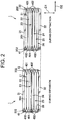
Fig. 2 is a schematic side view of batteries of the battery module according toFig.1 during expansion and contraction; -
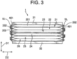
Fig. 3 is a schematic side view with sectioning a part of a battery module showing another embodiment; and -
Fig. 4 is a side view for illustrating a problem of a battery module of the conventional art. - Now, one embodiment according to the present invention shall be explained below based on
Figs. 1 and2 . As shown in these Figures, a battery module 1 includes multiple stacked batteries 21-26, a pair ofend plates busbar modules - Each of the multiple batteries 21-26 is formed e.g. from a laminated battery which consists of a lithium secondary battery, wherein it is a flat battery with a small thickness in the stacking direction D1. The multiple batteries 21-26 include
battery bodies 201 which are rectangular when seen from one side in the stacking direction D1, and pairs of ribbon-shaped electrode tabs 202, 202 (electrodes). The pairs ofelectrode tabs battery bodies 201 which form their short sides. As a result, a protrusion direction D2 of theelectrode tabs - Furthermore, one of the pair of
electrode tabs electrode tabs 202 forming positive electrodes are alternating with theelectrode tabs 202 forming negative electrodes. Additionally, the multiple batteries 21-26 are connected in series by usingbusbars 402 as described below to connect theelectrode tabs 202 forming positive electrodes to theelectrode tabs 202 forming negative electrodes which are adjacent. - The pair of
end plates end plates end plates - The pair of
busbar modules busbar modules busbar modules - Furthermore, the pair of
busbar modules substrate 401 andbusbars 402 supported thereon. Thesubstrates 401 consist of plastic etc. and are formed in a rectangular shape when seen in the protrusion direction D2. Thebusbars 402 consist of metallic material such as copper or brass etc. and theelectrode tabs 202 are jointed using welding or soldering etc. Saidbusbars 402 are exposed and supported on outer surfaces of thesubstrates 401, i.e. on their surfaces opposed to the batteries 21-26. While according to the present embodiment, thebusbars 402 are molded in one-pieces during producing thesubstrates 401, it may be also provided that thebusbars 402 are attached with any means after producing thesubstrates 401. - Moreover, the
busbars 402 are formed in a linear shape which is elongate along a orthogonal direction D3 orthogonal to the stacking direction D1 as well as the protrusion direction D2, wherein a plurality of thebusbars 402 are arranged adjacent to each other in the stacking direction D1. The number of thebusbars 402 corresponds to that of combinations of positive andnegative electrode tabs 202 which should be connected to each other. According to the present embodiment, threebusbars 402 are provided in abusbar module 41 on the one side in the protrusion direction D2 (the left side inFig.2 ) while twobusbars 402 are provided in abusbar module 42 on the other side in the protrusion direction D2 (the right side inFig.2 ). - Furthermore, slits SL (
Fig.1 ) as six insertion holes for inserting saidelectrode tabs 202 therethrough are formed in thesubstrates 401, arranged adjacent to each other in the stacking direction D1. The slits SL are formed in a linear form which is elongate along the orthogonal direction D3. In thebusbar module 41, the six slits SL are formed along both end edges of the threebusbars 402 in the stacking direction D1. Theelectrode tabs 202 inserted into the six respective slits SL of thebusbar module 41 protrude over the both end edges of thebusbars 402 in the stacking direction D1, wherein theelectrode tabs 202 are jointed to thebusbars 402 after being bent along surfaces of thebusbars 402. - In the
busbar module 42, four middle slits SL are formed along both end edges of twobusbars 402 in the stacking direction D1. Theelectrode tabs 202 inserted into the four respective central slits SL in thebusbar module 42 protrude over the both end edges of thebusbars 402 in the stacking direction D1, wherein theelectrode tabs 202 are jointed to thebusbars 402 after being bent along surfaces of thebusbars 402. Theelectrode tabs 202 inserted into two respective slits SL on both ends in thebusbar module 42 protrude over thesubstrate 401 and form electrodes of the battery module 1. - Furthermore, a groove G is formed nearly at a center of the
substrate 401 in the stacking direction D1 for inserting both ends of analuminum plate 5 as described below into the groove G. The groove G is formed along the orthogonal direction D3. - The
aluminum plate 5 is configured in a plate-shape with an essentially same size and a same thickness as thebattery body 201. Thealuminum plate 5 is arranged between twobatteries aluminum plate 5 is fixed in the stacking direction D1 to the batteries 21-26 by being sandwiched between the twobatteries - Moreover, both ends of the
aluminum plate 5 in the protrusion direction D2 are fitted into the grooves G of thebusbar modules aluminum plate 5 and thebusbar modules busbar modules end plates - Here, the wording "two of the multiple batteries 21-26 which are adjacent to a center" means two
batteries aluminum plate 5 in the stacking direction D1 (upper side inFig.2 ) is equal to that of batteries 24-26 on the other side (lower side inFig.2 ) if the number of the multiple batteries 21-26 is six (i.e. an even number) as shown in the present embodiment. - On the other side, it means a
battery 23 at the center in the stacking direction D1 and anadjacent battery 22 on the one side of thiscentral battery 23 in the stacking direction D1 or anadjacent battery 24 on the other side in the stacking direction D1 if the number of the multiple batteries 21-25 is less by one than in the present invention, i.e. five (namely an odd number). - According to the battery module 1 described above, the
aluminum plate 5 is arranged between twobatteries aluminum plate 5 and thebusbar modules aluminum plate 5 and thebusbar modules electrode tabs 202, as thebusbar modules busbar modules end plates busbar modules - Moreover, since a position offset of the slits SL of the
busbar modules electrode tabs 202 occurs around thealuminum plate 5 as a center, a reduction of the position offset can be achieved by half compared with the one-side fastening of the conventional art according toFig.4 . To explain more concretely, under the assumption that for example a variation of ± 2 mm occurs at the multiple batteries 21-26 as a whole with expansion or contraction, a position offset of maximal 4 mm will occur between theelectrode tabs 202 of thebattery 21 on the side which is not fastened and the slits SL of thebusbar modules electrode tabs 202 ofbatteries busbar modules electrode tabs 202 can be reduced which is accompanied by expansion or contraction of the batteries 21-26. - Furthermore, according to the above described embodiment, the
aluminum plate 5 made of aluminum was used as the fixing plate. This can obtain a cooling effect of the batteries 21-26. - Moreover, the
aluminum plate 5 according to the above described embodiment is arranged between twobatteries aluminum plate 5 into the center with a higher temperature. - It is to be noted that, while the fixing plate according to the above described embodiment consists of the
aluminum plate 5, it is not limited thereto. As the fixing plate, any element is possible which can be arranged between twobatteries busbar modules - Furthermore, while according to the above described embodiment, the
aluminum plate 5 is arranged between twobatteries aluminum plate 5, it is only required that it is arranged between any two of the multiple batteries 21-26 which are adjacent to each other, it may also be arranged for example between thebatteries electrode tab 202 at one end of thebattery 21 in the stacking direction D1 from the slit SL of thebusbar module electrode tab 202 can be reduced. - Moreover, while the
busbar modules end plates substrates 401 of thebusbar modules busbar modules end plates - Furthermore, although the
aluminum plate 5 according to the above described embodiment was fitted into the grooves G of thebusbar modules busbar modules aluminum plate 5 and fixed by fastening with screws. - Moreover, although according to the above described embodiment, the
busbars 402 supported on thesubstrates 401 were used to connect theelectrode tabs 202 of the batteries 21-26, the present invention is not limited to this. According to the present invention, onlysubstrates 401 into which theelectrode tabs 202 are to be inserted may be needed in order to connect the multiple batteries 21-26 in series by connecting theelectrode tabs 202 of the batteries 21-26 to each other which are adjacent to each other, and for example, theelectrode tabs 202 may be welded with each other withoutbusbars 402, as shown inFig.3 . - It is to be noted that the present invention is not limited to the above described embodiments. That means that various modifications can be implemented without departing from the core of the present invention.
-
- 1
- Battery module (battery pack)
- 5
- Aluminum plate (fixing plate)
- 21-26
- Battery
- 401
- Substrate
- 202
- Electrode tab (electrode)
- 402
- Busbar
- D2
- Protrusion direction
- SL
- Slit (Insertion hole)
Claims (3)
- A battery pack comprising:multiple batteries provided with electrodes protruding from each of both ends in a protrusion direction and stacked in a direction orthogonal to the protrusion direction of the electrodes;a substrate with insertion holes formed therein allowing the electrodes protruding from each of the both ends of the multiple batteries to be inserted therein; anda fixing plate sandwiched between any two of the multiple batteries which are adjacent to each other,wherein the fixing plate and the substrate are fixed to each other.
- The battery pack according to claim 1, wherein the fixing plate is formed from aluminum.
- The battery pack according to claim 1 or 2, wherein the fixing plate is sandwiched between two of the multiple batteries which are adjacent to a center of the multiple batteries.
Applications Claiming Priority (1)
| Application Number | Priority Date | Filing Date | Title |
|---|---|---|---|
| JP2018128864A JP6898889B2 (en) | 2018-07-06 | 2018-07-06 | Batteries |
Publications (1)
| Publication Number | Publication Date |
|---|---|
| EP3591740A1 true EP3591740A1 (en) | 2020-01-08 |
Family
ID=67137698
Family Applications (1)
| Application Number | Title | Priority Date | Filing Date |
|---|---|---|---|
| EP19183365.6A Pending EP3591740A1 (en) | 2018-07-06 | 2019-06-28 | Battery pack |
Country Status (4)
| Country | Link |
|---|---|
| US (1) | US20200013997A1 (en) |
| EP (1) | EP3591740A1 (en) |
| JP (1) | JP6898889B2 (en) |
| CN (1) | CN110690371B (en) |
Cited By (1)
| Publication number | Priority date | Publication date | Assignee | Title |
|---|---|---|---|---|
| CN112886118A (en) * | 2021-03-26 | 2021-06-01 | 东莞新能安科技有限公司 | Battery pack and electric equipment |
Families Citing this family (8)
| Publication number | Priority date | Publication date | Assignee | Title |
|---|---|---|---|---|
| KR102757441B1 (en) * | 2019-11-26 | 2025-01-17 | 주식회사 엘지에너지솔루션 | Battery module |
| CN111540872A (en) * | 2020-05-12 | 2020-08-14 | 远景动力技术(江苏)有限公司 | Busless battery module, assembly method of busless battery module, and battery pack |
| CN111653719B (en) * | 2020-05-26 | 2023-05-30 | 武汉中原长江科技发展有限公司 | A high energy density battery pack, multi-cell switching test device and test method |
| US20220311081A1 (en) * | 2021-03-26 | 2022-09-29 | Sion Power Corporation | Battery pack and related components and methods |
| JP7396412B1 (en) | 2022-08-31 | 2023-12-12 | 大日本印刷株式会社 | Energy storage unit |
| JP7741231B1 (en) * | 2024-03-29 | 2025-09-17 | 本田技研工業株式会社 | Busbar holder mounting method and busbar holder mounting device |
| JP7810744B2 (en) * | 2024-03-29 | 2026-02-03 | 本田技研工業株式会社 | Busbar holder and battery module |
| CN119994338B (en) * | 2025-02-11 | 2025-12-02 | 欣旺达动力科技股份有限公司 | A battery module, a battery pack, and an electrical device. |
Citations (7)
| Publication number | Priority date | Publication date | Assignee | Title |
|---|---|---|---|---|
| US20040021442A1 (en) * | 2002-07-30 | 2004-02-05 | Nissan Motor Co., Ltd. | Battery module |
| JP2009163932A (en) * | 2007-12-28 | 2009-07-23 | Sharp Corp | Battery pack |
| WO2012131801A1 (en) * | 2011-03-31 | 2012-10-04 | Necエナジーデバイス株式会社 | Battery pack |
| JP2013229266A (en) | 2012-04-27 | 2013-11-07 | Automotive Energy Supply Corp | Battery pack |
| JP2015060690A (en) * | 2013-09-18 | 2015-03-30 | 日立マクセル株式会社 | Battery stack and battery pack |
| US20160190663A1 (en) * | 2014-10-09 | 2016-06-30 | Simon Fraser University | Busbars with integrated cooling system for vehicle battery assemblies |
| EP3285311A1 (en) * | 2015-09-21 | 2018-02-21 | LG Chem, Ltd. | Battery module and battery pack comprising same |
Family Cites Families (13)
| Publication number | Priority date | Publication date | Assignee | Title |
|---|---|---|---|---|
| US8574740B2 (en) * | 2010-08-10 | 2013-11-05 | GM Global Technology Operations LLC | Molded frame with corrugated cooling fin for air-cooled battery |
| JP2013187046A (en) * | 2012-03-08 | 2013-09-19 | Nissan Motor Co Ltd | Battery pack |
| FR2988915A3 (en) * | 2012-03-30 | 2013-10-04 | Renault Sa | BATTERY MODULE STRUCTURE FOR SOFT-ENVELOPED LI-ION CELLS AND CORRESPONDING BATTERY MODULE |
| KR101509474B1 (en) * | 2012-06-13 | 2015-04-08 | 주식회사 엘지화학 | Battery Assembly Having Single Electrode Terminal Connecting Part |
| JP6011876B2 (en) * | 2013-09-13 | 2016-10-19 | 株式会社オートネットワーク技術研究所 | Power storage module |
| CN204303901U (en) * | 2014-11-25 | 2015-04-29 | 宁德时代新能源科技有限公司 | Battery pole ear syndeton and comprise the flexible-packed battery module of this syndeton |
| KR102047482B1 (en) * | 2015-10-30 | 2019-12-02 | 주식회사 엘지화학 | Battery module and battery pack including the same |
| CN108140767B (en) * | 2015-11-05 | 2020-12-22 | 株式会社Lg化学 | battery module |
| CN105514498B (en) * | 2015-12-01 | 2019-04-26 | 浙江超威创元实业有限公司 | A kind of power battery module and electric vehicle convenient for assembling automatically |
| CN205376598U (en) * | 2015-12-30 | 2016-07-06 | 宁德时代新能源科技股份有限公司 | Battery is frame for module |
| DE102016118977B4 (en) * | 2016-10-06 | 2022-01-20 | Clarios Advanced Solutions Gmbh | Energy storage module and method of assembly |
| KR102036085B1 (en) * | 2016-12-23 | 2019-10-24 | 에스케이이노베이션 주식회사 | Secondary battery module |
| CN206742365U (en) * | 2017-04-21 | 2017-12-12 | 安徽欧鹏巴赫新能源科技有限公司 | Soft package power lithium ion battery module |
-
2018
- 2018-07-06 JP JP2018128864A patent/JP6898889B2/en active Active
-
2019
- 2019-06-28 EP EP19183365.6A patent/EP3591740A1/en active Pending
- 2019-06-28 US US16/457,275 patent/US20200013997A1/en not_active Abandoned
- 2019-07-08 CN CN201910609623.1A patent/CN110690371B/en active Active
Patent Citations (8)
| Publication number | Priority date | Publication date | Assignee | Title |
|---|---|---|---|---|
| US20040021442A1 (en) * | 2002-07-30 | 2004-02-05 | Nissan Motor Co., Ltd. | Battery module |
| JP2009163932A (en) * | 2007-12-28 | 2009-07-23 | Sharp Corp | Battery pack |
| WO2012131801A1 (en) * | 2011-03-31 | 2012-10-04 | Necエナジーデバイス株式会社 | Battery pack |
| EP2693516A1 (en) * | 2011-03-31 | 2014-02-05 | NEC Energy Devices, Inc. | Battery pack |
| JP2013229266A (en) | 2012-04-27 | 2013-11-07 | Automotive Energy Supply Corp | Battery pack |
| JP2015060690A (en) * | 2013-09-18 | 2015-03-30 | 日立マクセル株式会社 | Battery stack and battery pack |
| US20160190663A1 (en) * | 2014-10-09 | 2016-06-30 | Simon Fraser University | Busbars with integrated cooling system for vehicle battery assemblies |
| EP3285311A1 (en) * | 2015-09-21 | 2018-02-21 | LG Chem, Ltd. | Battery module and battery pack comprising same |
Cited By (1)
| Publication number | Priority date | Publication date | Assignee | Title |
|---|---|---|---|---|
| CN112886118A (en) * | 2021-03-26 | 2021-06-01 | 东莞新能安科技有限公司 | Battery pack and electric equipment |
Also Published As
| Publication number | Publication date |
|---|---|
| US20200013997A1 (en) | 2020-01-09 |
| JP2020009604A (en) | 2020-01-16 |
| CN110690371A (en) | 2020-01-14 |
| CN110690371B (en) | 2023-06-09 |
| JP6898889B2 (en) | 2021-07-07 |
Similar Documents
| Publication | Publication Date | Title |
|---|---|---|
| EP3591740A1 (en) | Battery pack | |
| US9209447B2 (en) | Secondary battery module | |
| TWI497805B (en) | Battery unit fuse | |
| JP6281398B2 (en) | Battery module | |
| JP5754497B2 (en) | Battery pack and battery pack manufacturing method | |
| JP2007265945A (en) | Lamination cell accumulation type battery and battery module | |
| US20210091404A1 (en) | Separator, battery module and battery module production method | |
| US11167631B2 (en) | Assembly of electric accumulators | |
| CN114335910A (en) | connection module | |
| JP6469062B2 (en) | Connection module | |
| JP6401656B2 (en) | Wiring member | |
| JP7241291B2 (en) | Battery modules and battery packs | |
| CN109980143B (en) | Electric storage device | |
| WO2019010449A1 (en) | Modular housing for battery systems | |
| WO2018155090A1 (en) | Battery pack and busbar for battery pack | |
| US11417934B2 (en) | Connection element for mechanical and electrical connection to a contact element of an electrical storage cell | |
| JP7174345B2 (en) | power storage device | |
| JP6233076B2 (en) | Battery module | |
| JP6582570B2 (en) | Battery module | |
| JP7288671B2 (en) | secondary battery pack | |
| JP6610007B2 (en) | Battery pack | |
| CN118472565A (en) | Battery device | |
| JP2020177901A (en) | Rechargeable battery module | |
| CN120322906A (en) | Assembly of a battery cell of an energy storage element and method for assembling the assembly | |
| JP2018006159A (en) | Battery module |
Legal Events
| Date | Code | Title | Description |
|---|---|---|---|
| PUAI | Public reference made under article 153(3) epc to a published international application that has entered the european phase |
Free format text: ORIGINAL CODE: 0009012 |
|
| STAA | Information on the status of an ep patent application or granted ep patent |
Free format text: STATUS: REQUEST FOR EXAMINATION WAS MADE |
|
| 17P | Request for examination filed |
Effective date: 20190628 |
|
| AK | Designated contracting states |
Kind code of ref document: A1 Designated state(s): AL AT BE BG CH CY CZ DE DK EE ES FI FR GB GR HR HU IE IS IT LI LT LU LV MC MK MT NL NO PL PT RO RS SE SI SK SM TR |
|
| AX | Request for extension of the european patent |
Extension state: BA ME |
|
| RBV | Designated contracting states (corrected) |
Designated state(s): AL AT BE BG CH CY CZ DE DK EE ES FI FR GB GR HR HU IE IS IT LI LT LU LV MC MK MT NL NO PL PT RO RS SE SI SK SM TR |
|
| STAA | Information on the status of an ep patent application or granted ep patent |
Free format text: STATUS: EXAMINATION IS IN PROGRESS |
|
| 17Q | First examination report despatched |
Effective date: 20201005 |
|
| RAP3 | Party data changed (applicant data changed or rights of an application transferred) |
Owner name: YAZAKI CORPORATION |