EP3591682A1 - Load detection sensor - Google Patents
Load detection sensor Download PDFInfo
- Publication number
- EP3591682A1 EP3591682A1 EP18761352.6A EP18761352A EP3591682A1 EP 3591682 A1 EP3591682 A1 EP 3591682A1 EP 18761352 A EP18761352 A EP 18761352A EP 3591682 A1 EP3591682 A1 EP 3591682A1
- Authority
- EP
- European Patent Office
- Prior art keywords
- electrode
- spacer
- detection sensor
- sheet
- annular member
- Prior art date
- Legal status (The legal status is an assumption and is not a legal conclusion. Google has not performed a legal analysis and makes no representation as to the accuracy of the status listed.)
- Granted
Links
Images



Classifications
-
- H—ELECTRICITY
- H01—ELECTRIC ELEMENTS
- H01H—ELECTRIC SWITCHES; RELAYS; SELECTORS; EMERGENCY PROTECTIVE DEVICES
- H01H3/00—Mechanisms for operating contacts
- H01H3/02—Operating parts, i.e. for operating driving mechanism by a mechanical force external to the switch
- H01H3/14—Operating parts, i.e. for operating driving mechanism by a mechanical force external to the switch adapted for operation by a part of the human body other than the hand, e.g. by foot
- H01H3/141—Cushion or mat switches
-
- H—ELECTRICITY
- H01—ELECTRIC ELEMENTS
- H01H—ELECTRIC SWITCHES; RELAYS; SELECTORS; EMERGENCY PROTECTIVE DEVICES
- H01H2213/00—Venting
- H01H2213/002—Venting with external pressure
-
- H—ELECTRICITY
- H01—ELECTRIC ELEMENTS
- H01H—ELECTRIC SWITCHES; RELAYS; SELECTORS; EMERGENCY PROTECTIVE DEVICES
- H01H2213/00—Venting
- H01H2213/016—Venting in adhesive layer
-
- H—ELECTRICITY
- H01—ELECTRIC ELEMENTS
- H01H—ELECTRIC SWITCHES; RELAYS; SELECTORS; EMERGENCY PROTECTIVE DEVICES
- H01H2227/00—Dimensions; Characteristics
- H01H2227/024—Spacer elements
-
- H—ELECTRICITY
- H01—ELECTRIC ELEMENTS
- H01H—ELECTRIC SWITCHES; RELAYS; SELECTORS; EMERGENCY PROTECTIVE DEVICES
- H01H2229/00—Manufacturing
- H01H2229/024—Packing between substrate and membrane
- H01H2229/028—Adhesive
-
- H—ELECTRICITY
- H01—ELECTRIC ELEMENTS
- H01H—ELECTRIC SWITCHES; RELAYS; SELECTORS; EMERGENCY PROTECTIVE DEVICES
- H01H9/00—Details of switching devices, not covered by groups H01H1/00 - H01H7/00
- H01H9/02—Bases, casings, or covers
- H01H9/04—Dustproof, splashproof, drip-proof, waterproof, or flameproof casings
- H01H9/047—Dustproof, splashproof, drip-proof, waterproof, or flameproof casings provided with venting means
Definitions
- the annular member disposed in the opening of the spacer has no adhesion to both of the first electrode sheet and the second electrode sheet, a variation in temperature environment due to the adhesive layer does not occur at the edge portion of the opening of the annular member.
- the degree of inward deflection inside the annular member in the opening of the spacer due to pressing of at least one of the first electrode sheet and the second electrode sheet substantially does not change.
- the load necessary for contact between the first electrode and the second electrode can be prevented from varying.
- the load detection sensor capable of detecting a load properly, is achieved.
- the annular member is in contact with both of the first electrode sheet and the second electrode sheet.
- the annular member can support the first electrode sheet and the second electrode sheet, more stably. Therefore, variation in the load necessary for contact between the first electrode and the second electrode, can be further reduced.
- the spacer has a slit connected to the opening, at least one of the first electrode sheet and the second electrode sheet has an air outlet, and a communication member is disposed in the slit, the communication member allowing communication between the vent of the annular member and the air outlet.
- the annular member overlaps the first electrode and the second electrode.
- the annular member is interposed between the first electrode and the second electrode.
- the distance between the first electrode and the second electrode is substantially constantly retained by the annular member. Therefore, the variation in distance between the first electrode and the second electrode between a plurality of load detection sensors can be reduced by the annular member, so that the variation in the load necessary for contact between the first electrode and the second electrode between the load detection sensors is reduced.
- the annular member even when the annular member has no adhesion to the first electrode sheet and the second electrode sheet, the annular member is inhibited from moving in the opening of the spacer. Under no load in which no load is applied to the load detection sensor, stress can be prevented from occurring in a direction in which the spacer and the electrode sheet adhering through the adhesive layer peel off.
- the first electrode and the second electrode can be less damaged in comparison to a case where the annular member overlaps the first electrode and the second electrode.
- a sum of a thickness of the spacer and a thickness of the adhesive layer is approximately equivalent to a height of the annular member.
- the annular member even when the annular member has no adhesion to the first insulating sheet and the second insulating sheet, the annular member is inhibited from moving in the opening of the spacer. Under no load in which no load is applied to the load detection sensor, stress can be prevented from occurring in a direction in which the spacer and the electrode sheet adhering through the adhesive layer peel off.
- the load detection sensor capable of detecting a load properly, can be provided.
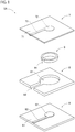
- FIG. 1 is an exploded view of the configuration of a load detection sensor according to a first embodiment.
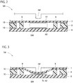
- FIG. 2 is a sectional view of the configuration of the load detection sensor.
- the load detection sensor 5A includes a first electrode sheet 6, a second electrode sheet 7, a spacer 8, an annular member 9, and adhesive layers 10 as main constituent elements. Note that, for convenience, the adhesive layers 10 are omitted in FIG. 1 .
- the first electrode sheet 6 includes a first insulating sheet 61 and a first electrode 62.
- the first insulating sheet 61 is a resin insulating sheet having flexibility. Examples of reins as the material of the first insulating sheet 61 include polyethylene terephthalate (PET), polyimide (PI), and polyethylene naphthalate (PEN).
- the first electrode 62 that is one switch element included in a switch SW in the load detection sensor 5A ( FIG. 2 ), includes, for example, a substantially-circular metallic printed layer.
- the spacer 8 interposed between the first electrode sheet 6 and the second electrode sheet 7, includes a resin insulating sheet having flexibility.
- resins as the material of the spacer 8 include PET, PI, and PEN. Note that the spacer 8 may be identical in material to or different in material from the first insulating sheet 61 or the second insulating sheet 71.
- the spacer 8 has a slit 82 allowing communication between the space in the opening 81 and the external space of the load detection sensor 5A.
- the slit 82 serves as an air vent with the spacer 8 superimposed on the first electrode sheet 6 and the second electrode sheet 7.
- the air vent is a passage for deflation of the air in the opening 81 to the outside of the load detection sensor 5A.
- examples of resins as the material of the annular member 9 include PET, PI, and PEN.
- the annular member 9 may be identical in material to or different in material from the spacer 8, the first insulating sheet 61, or the second insulating sheet 71.
- the spacer 8 and the annular member 9 are preferably identical in material in order to reduce a variation due to expansion between the height of the annular member 9 and the height of the spacer 8 and the adhesive layers 10.
- the annular member 9 has a vent 91 for deflation of the air inside the annular member 9, namely, in the opening of the annular member 9 in the opening 81 of the spacer 8.
- the vent 91 is a slit formed from one end to the other end in the height direction of the annular member 9, but may be a through hole penetrating from the outer circumferential face to the inner circumferential face of the annular member.
- the annular member 9 according to the present embodiment has a break at part in the circumferential direction of the annular member 9 due to the vent 91.
- the length of the break in the circumferential direction of the annular member 9, is preferably not more than one fifth of the entire length in the circumferential direction of the annular member 9 including the break.
- one break is provided, but a plurality of breaks may be provided.
- the sum of the lengths of the breaks in the circumferential direction of the annular member 9 is preferably not more than one third of the entire length in the circumferential direction of the annular member 9 including the plurality of breaks.
- the annular member 9 includes one break or intermittent breaks.
- the number of breaks is one or less.
- the respective adhesive layers 10 are disposed between the first insulating sheet 61 of the first electrode sheet 6 and the spacer 8 and between the second insulating sheet 71 of the second electrode sheet 7 and the spacer 8.
- the adhesive layers 10 are not particularly limited as long as the first insulating sheet 61, the second insulating sheet 71, and the spacer 8 bond together.
- the adhesive layers 10 include glue, adhesive, and double-sided tape including a base material, such as PET or nonwoven fabric, having each face provided with glue or adhesive.
- the material of the adhesive layers 10 include thermoplastic resin, thermosetting resin, and photo-curable resin.
- examples of the glue include silicon glue, urethane glue, and acrylic glue.
- the load detection sensor 5A includes the above constituent elements in combination. That is the load detection sensor 5A includes the first electrode sheet 6 adhering on the one face side of the spacer 8 through the adhesive layer 10 and the second electrode sheet 7 adhering on the other face side of the spacer 8 through the adhesive layer 10 with the annular member 9 disposed in the opening 81 of the spacer 8.
- the annular member 9 is in contact with both of the first insulating sheet 61 exposed on one opening face side of the opening 81 of the spacer 8 and the second insulating sheet 71 exposed on the other opening face side of the opening 81. Specifically, one end of the annular member 9 is in contact with the inner circumferential portion exposed from the opening 81, in the first insulating sheet 61, and the other end of the annular member 9 is in contact with the inner circumferential portion exposed from the opening 81, in the second insulating sheet 71.
- the annular member 9 can support the inner circumferential portion exposed from the opening 81, in the first insulating sheet 61 and the inner circumferential portion exposed from the opening 81, in the second insulating sheet 71. Note that the annular member 9 has no adhesion to both of the first insulating sheet 61 exposed on the one opening face side of the opening 81 of the spacer 8 and the second insulating sheet 71 exposed on the other opening face side of the opening 81.
- the vent 91 of the annular member 9 is in communication with the outside of the load detection sensor 5A through the slit 82 of the spacer 8, with the outer circumferential face of the annular member 9 disposed apart from the spacer 8. Note that only part of the outer circumferential face of the annular member 9 may be in contact with the spacer 8. That is the outer circumferential face of the annular member 9 requires at least spacing apart from part of the spacer 8.
- the first electrode 62 is located inside one opening end in the annular member 9, and the second electrode 72 is located inside the other opening end in the annular member 9.
- the first electrode 62 and the second electrode 72 opposed to each other inside the annular member 9, are included in the switch SW.
- FIG. 3 is a view of the ON state of the load detection sensor 5A.
- Downward movement of the pressing portion PP due to reception of a load causes contact with the face opposite to the face on the spacer 8 side of the second insulating sheet 71 of the second electrode sheet 7, resulting in pressing of the second insulating sheet 71.
- Inward deflection of the second insulating sheet 71 inside the annular member 9 due to the press of the pressing portion PP causes the second electrode 72 in contact with the first electrode 62, so that the switch SW of the load detection sensor 5A changes to the ON state.
- the load is detected by a vehicular control unit, not illustrated, electrically connected to the second electrode 72 and the first electrode 62.
- deflection of the second insulating sheet 71 causes the air inside the annular member 9 to discharge outside the annular member 9 through the vent 91 of the annular member 9 and causes the air in the opening 81 of the spacer 8 to discharge through the slit 82. Therefore, inhibition of deflection between the first insulating sheet 61 and the second insulating sheet 71 due to the air inside the annular member 9 and the air in the opening 81 of the spacer 8, is avoided, so that the switch SW of the load detection sensor 5A changes to the ON state, properly.
- the load detection sensor 5A includes: the first electrode sheet 6 including the first electrode 62; the second electrode sheet 7 including the second electrode 72 opposed to the first electrode 62; and the spacer 8 interposed between the first electrode sheet 6 and the second electrode sheet 7, the spacer 8 having the opening 81 between the first electrode 62 and the second electrode 72.
- the load detection sensor 5A includes: the annular member 9 disposed in the opening 81 of the spacer 8; and the respective adhesive layers 10 disposed between the spacer 8 and the first electrode sheet 6 and between the spacer 8 and the second electrode sheet 7.
- the annular member 9 supports the inner circumferential portion exposed from the opening 81 of the first electrode sheet 6 and the inner circumferential portion exposed from the opening 81 of the second electrode sheet 7.
- the annular member 9 has no adhesion to both of the first electrode sheet 6 exposed at the opening 81 of the spacer 8 and the second electrode sheet 7 exposed at the opening 81 of the spacer 8.
- the adhesive layer 10 tends to soften under a high-temperature environment and tends to harden under a low-temperature environment, easily.
- variation of the adhesive layers 10 at the edge portion of the opening 81 of the spacer 8, corresponding to a temperature environment causes a variation in the degree of inward deflection to the opening 81 of the spacer 8 between the first electrode sheet 6 and the second electrode sheet 7.
- the variation in the degree of deflection causes a variation in the load necessary for contact between the first electrode 62 and the second electrode 72.
- the annular member 9 disposed in the opening 81 of the spacer 8 has no adhesion, a variation in temperature environment due to the adhesive layers 10 does not occur at the edge portion of the opening of the annular member 9.
- the degree of inward deflection inside the annular member 9 due to pressing of the second electrode sheet 7 substantially does not change. Therefore, in comparison to a case where the annular member 9 adheres to at least one of the first electrode sheet 6 and the second electrode sheet 7 through an adhesive layer, the load necessary for contact between the first electrode 62 and the second electrode 72 can be prevented from varying.
- the presence of the annular member 9 causes less load to be applied to the adhesive layers 10, and thus the adhesive layers 10 are less likely to be creep-deformed. Even if the adhesive layers 10 are creep-deformed by long-term pressing of the load detection sensor 5A, the distance between the first electrode sheet 6 and the second electrode sheet 7 is substantially constantly retained by the annular member 9. As a result, variation in the load necessary for contact between the first electrode 62 and the second electrode 72, along with creep deformation, can be reduced.
- the load detection sensor 5A capable of detecting a load properly, is achieved.
- the annular member 9 according to the present embodiment is in contact with both of the first electrode sheet 6 exposed at the opening 81 of the spacer 8 and the second electrode sheet 7 exposed at the opening 81 of the spacer 8.
- the annular member 9 can support the first electrode sheet 6 and the second electrode sheet 7, more stably. Therefore, variation in the load necessary for contact between the first electrode 62 and the second electrode 72, can be further reduced.
- the outer circumferential face of the annular member 9 according to the present embodiment is spaced apart from the spacer 8.
- the adhesive layers 10 can be stored in the gap between the annular member 9 and the spacer 8. Therefore, flowing of the softened adhesive layers 10 between the annular member 9, the first electrode sheet 6, and the second electrode sheet 7, can be avoided. As a result, variation in the load necessary for contact between the first electrode 62 and the second electrode 72, can be further reduced.
- the annular member 9 has the vent 91 for deflation of the air inside the annular member 9 in the opening 81 of the spacer 8.
- the air inside the annular member 9 discharges from the vent 91. Therefore, inhibition of deflection of the second electrode sheet 7 due to the air inside the annular member 9 is avoided, so that the load detection sensor can be prevented from performing false detection.
- the annular member 9 in a case where the sheet face of the first electrode sheet 6 is viewed in plan view, the annular member 9 does not overlap the first electrode 62 and the second electrode 72. This arrangement enables the first electrode 62 and the second electrode 72 to be less damaged in comparison to a case where the annular member 9 overlaps the first electrode 62 and the second electrode 72.
- the height of the annular member 9 is approximately equivalent to the sum of the thickness of the adhesive layer 10 between the first insulating sheet 61 and the spacer 8, the thickness of the adhesive layer 10 between the second insulating sheet 71 and the spacer 8, and the thickness of the spacer 8.
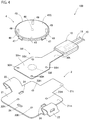
- FIG. 4 is an exploded view of the configuration of the load detection sensor unit according to the second embodiment.
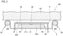
- FIG. 5 is a sectional view of the load detection sensor unit attached to S-shaped springs of a seat device. Note that, for convenience, a load detection sensor 5B is not illustrated in section in FIG. 5 .
- the load detection sensor unit 100 includes a support plate 2, an upper case 4, and the load detection sensor 5B as main constituent elements.
- the support plate 2 includes a mount portion 21 on which the load detection sensor 5B is mounted, and a pair of hook portions 22 coupled to the mount portion 21.
- the mount portion 21 includes: a wide main block mount portion 21m; and a tail block mount portion 21t extending from the main block mount portion 21m, the tail block mount portion 21t being narrower in width than the main block mount portion 21m.
- the hook portions 22 are coupled to the main block mount portion 21m.
- the mount portion 21 and the pair of hook portions 22 are integrally formed by bending of a metallic plate. Note that the plate thickness of the support plate 2 is, for example, 0.8 mm.
- a main block 50m in the load detection sensor 5B is disposed on a face of the main block mount portion 21m, the face being opposed to a seat cushion SC.
- the main block mount portion 21m has a plurality of circular through holes 20H penetrating through the support plate 2, and further has a plurality of substantially-rectangular case-locking openings 24.
- the main block mount portion 21m has a degree of size so as to be disposed between two mutually opposed S-shaped springs BN from a plurality of S-shaped springs BN stretched alongside across the opening of a seat frame in the vehicular seat device.
- the S-shaped springs BN each are a spring serpentine in an S shape.
- the tail block mount portion 21t having a substantially rectangular shape, extends in a direction substantially perpendicular to a direction passing through the pair of hook portions 22 in plan view of the main block mount portion 21m.
- a tail block 50t in the load detection sensor 5B is disposed on a face of the tail block mount portion 21t, the face being opposed to the seat cushion SC. Note that, according to the present embodiment, the width in a direction perpendicular to the extending direction of the tail block mount portion 21t is smaller than the width of the tail block 50t of the load detection sensor 5B, and the length in the extending direction of the tail block mount portion 21t is smaller than the length of the tail block 50t of the load detection sensor 5B.
- the upper case 4 is a member covering the main block 50m mounted on the main block mount portion 21m of the mount portion 21 such that, for example, a switch SW in the main block 50m is protected. As illustrated in FIG. 5 , the upper case 4 doubles as a pressing member that presses the switch SW of the load detection sensor 5B by pressing from the seat cushion SC.
- the upper case 4 includes a top wall 45 and a frame wall 48.
- the top wall 45 is a tabular member that is substantially rectangular.
- the frame wall 48 of the upper case 4 includes a plurality of divided portions connected to the top wall 45 in the outer circumference of the top wall 45.
- a hook piece 47 is connected to the top wall 45 between each of the plurality of divided portions of the frame wall 48.
- the hook pieces 47 individually engage with the case-locking openings 24 at the main block mount portion 21m of the support plate 2. Individual engagement of the hook pieces 47 with the case-locking openings 24 regulates the relative movement in the mount in-plane direction of the main block mount portion 21m between the support plate 2 and the upper case 4.
- the top wall 45 of the upper case 4 has a bottom face from which a pressing portion 46 protrudes, the bottom face being opposed to the mount portion 21 of the support plate 2.
- the leading end of the pressing portion 46 has a flat shape. Note that the leading end of the pressing portion 46 may have a protruding curved shape. According to the present embodiment, with the upper case 4 covering the load detection sensor 5B mounted on the mount portion 21 and the hook pieces 47 engaging with the corresponding case-locking openings 24, the leading end of the pressing portion 46 is in contact with the load detection sensor 5B, but is not necessarily in contact with the load detection sensor 5B.
- the upper face 45S of the top wall 45 of the upper case 4 is spaced apart from the lower face of the seat cushion SC, but may be in contact with the lower face of the seat cushion SC.
- the upper face 45S has a flat shape.
- the upper face 45S is a pressure-receiving face that receives pressing from the seat cushion SC.
- the upper face 45S is larger in area than the portion in contact with the switch SW of the load detection sensor 5B, in the pressing portion 46.
- the upper case 4 is formed of material harder than that of the seat cushion SC. Therefore, the pressing portion 46 that is part of the upper case 4 is formed of the material harder than that of the seat cushion SC. Because, generally, the seat cushion SC includes foamed urethane resin, examples of resin as the material of the upper case 4 include polycarbonate (PC), polybutylene terephthalate (PBT), polyamide (PA), phenolic resin, and epoxy resin.
- PC polycarbonate
- PBT polybutylene terephthalate
- PA polyamide
- epoxy resin epoxy resin
- the load detection sensor 5B includes: the main block 50m that is substantially rectangular; and the tail block 50t connected to the main block 50m, the tail block 50t being narrower in width than the main block 50m.
- the main block 50m is provided with the switch SW.
- a through hole 50H is formed near each apex of the main block 50m.
- the through holes 50H are formed in positional relationship so as to be superimposed on the plurality of through holes 20H formed through the mount portion 21 of the support plate 2.
- the tail block 50t coupled to the main block 50m extends apart from the main block 50m.
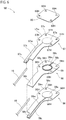
- FIG. 6 is an exploded view of the load detection sensor according to the second embodiment.
- FIG. 7 is a sectional view of the load detection sensor according to the second embodiment.
- the load detection sensor 5B according to the present embodiment includes a first electrode sheet 56, a second electrode sheet 57, a spacer 58, an annular member 59, adhesive layers 10 as main constituent elements. Note that, for convenience, the adhesive layers 10 are omitted in FIG. 6 .
- the first electrode sheet 56 includes a first insulating sheet 56s, a first electrode 56e, and a first terminal 56c.
- the first insulating sheet 56s is a resin insulating sheet having flexibility.
- the first insulating sheet 56s includes a main block 56m and a tail block 56t connected to the main block 56m.
- a leading end portion opposite to the main block 56m is narrower in width than the other portion of the tail block 56t.
- the main block 56m has through holes 56H. Note that the through holes 56H are part of the through holes 50H of the load detection sensor 5B.
- resin as the material of the first insulating sheet 56s include PET, PI, and PEN.
- the first electrode 56e is provided at substantially the center on one face of the main block 56m.
- the first electrode 56e includes a conductive layer, for example, a substantially-circular metallic printed layer.
- the first terminal 56c includes a conductive layer, for example, a substantially-quadrangular metallic layer.
- the first terminal 56c is provided on a face of the leading end portion of the tail block 56t, the face being on the side on which the first electrode 56e is provided.
- the first electrode 56e and the first terminal 56c are mutually electrically connected through a first wire 56w.
- the second electrode sheet 57 includes a second insulating sheet 57s, a metallic plate 60, an adhesive layer for metal 70, a second electrode 57e, and a second terminal 57c.
- the second electrode sheet 7 according to the first embodiment includes one layer of the second insulating sheet 71, whereas the second electrode sheet 57 according to the present embodiment includes two layers of the second insulating sheet 57s and the metallic plate 60.
- the second insulating sheet 57s disposed on the seat cushion SC ( FIG. 4 ) side with respect to the first electrode sheet 56 is a resin insulating sheet, similarly to the first insulating sheet 56s.
- the second insulating sheet 57s is smaller in thickness than the first insulating sheet 56s, and is less in thickness than the metallic plate 60.
- the second insulating sheet 57s includes: a main block 57m identical in shape to the main block 56m of the first insulating sheet 56s; and a tail block 57t connected to the main block 57m, the tail block 57t being identical in shape to the tail block 56t of the first insulating sheet 56s except for the leading end portion.
- the leading end portion of the tail block 57t is narrower in width than the other portion of the tail block 57t.
- the main block 57m has through holes 57H. Note that the through holes 57H are part of the through holes 50H of the load detection sensor 5B, similarly to the through holes 56H of the first insulating sheet 56s.
- resin as the material of the second insulating sheet 57s include PET, PI, and PEN.
- the second insulating sheet 57s may be identical in material to or different in material from the first insulating sheet 56s.
- the metallic plate 60 bonds to one face of the second insulating sheet 57s through the adhesive layer for metal 70. According to the present embodiment, the metallic plate 60 bonds to the face on the seat cushion SC side of the main block 57m that is part of the second insulating sheet 57s.
- the metallic plate 60 has through holes 60H. Note that the through holes 60H are part of the through holes 50H of the load detection sensor 5B. Examples of the material of the metallic plate 60 include, but are not particularly limited to, copper and stainless steel.
- the adhesive layer for metal 70 is disposed between the main block 57m of the second insulating sheet 57s and the metallic plate 60.
- the adhesive layer for metal 70 is not particularly limited as long as the second insulating sheet 57s and the metallic plate 60 bond together.
- Examples of the adhesive layer for metal 70 include glue, adhesive, and double-sided tape including a base material, such as PET or nonwoven fabric, having each face provided with glue or adhesive.
- Examples of the material of the adhesive layer for metal 70 include thermoplastic resin, thermosetting resin, and photo-curable resin. Note that the adhesive layer for metal 70 may be identical in material to or different in material from the adhesive layers 10.
- the glass-transition temperature Tg of the adhesive layer for metal 70 is preferably 85°C or more.
- a glass-transition temperature Tg of 85°C or more causes the adhesive layer for metal 70 to be less likely to flow even in a high-temperature environment, such as the inside of a motor vehicle under a blazing sun, so that false detection of seating due to flowing of the adhesive layer for metal 70 can be inhibited.
- the adhesive layer for metal 70 may be disposed over the entire faces between the second insulating sheet 57s and the metallic plate 60 or may be dispersedly disposed at a plurality of portions between the second insulating sheet 57s and the metallic plate 60.
- the second electrode 57e similar in configuration to the first electrode 56e is provided at substantially the center on one face of the main block 57m of the second insulating sheet 57s.
- the position for provision of the second electrode 57e allows superimposition of the second electrode 57e on the first electrode 56e at superimposition of the first electrode sheet 56 and the second electrode sheet 57.
- the second terminal 57c similar in configuration to the first terminal 56c is provided on a face of the leading end portion of the tail block 57t, the face being on the side on which the second electrode 57e is provided.
- first terminal 56c and the second terminal 57c are exposed without being located between the first insulating sheet 56s and the second insulating sheet 57s.
- the second electrode 57e and the second terminal 57c are mutually electrically connected through a second wire 57w.
- the spacer 58 disposed between the first electrode sheet 56 and the second electrode sheet 57 includes a resin insulating sheet having flexibility.
- the spacer 58 includes a main block 58m and a tail block 58t connected to the main block 58m.
- the main block 58m is similar in outer shape to the main blocks 56m and 57m of the first insulating sheet 56s and the second insulating sheet 57s.
- the tail block 58t has a shape identical to the shape in which the leading end portion narrow in width is excluded from each of the tail blocks 56t and 57t of the first insulating sheet 56s and the second insulating sheet 57s.
- the spacer 58 has through holes 58H, similarly to the first insulating sheet 56s and the second insulating sheet 57s. Note that the through holes 58H are part of the through holes 50H of the load detection sensor 5B. Examples of resin as the material of the spacer 58 include PET, PI, and PEN, similarly to the first insulating sheet 56s and the second insulating sheet 57s. Note that the spacer 58 may be identical in material to or different in material from the first insulating sheet 56s or the second insulating sheet 57s.
- the main block 58m of the spacer 58 has an opening 58c penetrating from one face side to the other face side of the spacer 58.
- the first electrode 56e and the second electrode 57e are opposed to each other through the opening 58c.
- the circumferential-edge shape of the opening 58c is, for example, substantially circular.
- the opening 58c is formed smaller in diameter than the first electrode 56e and the second electrode 57e.
- the opening 81 of the spacer 8 according to the first embodiment is formed larger in diameter than the first electrode 62 and the second electrode 72.
- the opening 58c of the spacer 58 according to the present embodiment is formed smaller in diameter than the first electrode 56e and the second electrode 57e. Therefore, for the opening 58c according to the present embodiment, in a case where the spacer 58 is superimposed on the first electrode sheet 56 and the second electrode sheet 57, the opening 58c of the spacer 58 is located inside the circumferential edges of the first electrode 56e and the second electrode 57e.
- the spacer 58 has a slit 58b through which the space in the opening 58c is in communication with the external space of the load detection sensor 5B.
- the slit 58b serves as an air vent with the first electrode sheet 56, the spacer 58, and the second electrode sheet 57 in superimposition on each other.
- the air vent is a passage for deflation of the air in the opening 58c to the outside of the load detection sensor 5B.
- the annular member 59 is a member in an annular shape disposed in the opening 58c of the spacer 58.
- the outer diameter of the annular member 59 is smaller than the diameter of the opening 58c of the spacer 58, and is smaller than the diameters of the first electrode 56e and the second electrode 57e.
- the inner diameter of the annular member 9 according to the first embodiment is larger than the diameters of the first electrode 62 and the second electrode 72, whereas the inner diameter and the outer diameter of the annular member 59 according to the present embodiment both are smaller than the diameters of the first electrode 56e and the second electrode 57e. Therefore, as illustrated in FIG. 8 , the annular member 59 and the second electrode 57e according to the present embodiment overlap in plan view of a sheet face of of the second electrode sheet 57 when the spacer 58, the first electrode sheet 56, and the second electrode sheet 57 are stacked. As illustrated in FIG.
- the sum of the height of the annular member 59, the thickness of the first electrode 56e, and the thickness of the second electrode 57e is approximately equivalent to the sum of the thickness of the adhesive layer 10 between the first insulating sheet 61 and the spacer 8, the thickness of the adhesive layer 10 between the second insulating sheet 71 and the spacer 8, and the thickness of the spacer 8.
- the annular member 59 is preferably larger in elastic modulus than the adhesive layers 10, similarly to the first embodiment.
- Examples of resin as the material of the annular member 59 include PET, PI, and PEN, similarly to the first insulating sheet 56s, the second insulating sheet 57s, and the spacer 58.
- the annular member 59 may be identical in material to or different in material from the spacer 58, the first insulating sheet 56s, or the second insulating sheet 57s.
- the spacer 58 and the annular member 59 are preferably identical in material in order to reduce a variation due to expansion between the height of the annular member 59 and the height of the spacer 58.
- the annular member 59 has a vent 59b for deflation of the air inside the annular member 59 in the opening 58c in the spacer 58.
- the vent 59b is a slit formed from one end to the other end in the height direction of the annular member 59, but may be a through hole penetrating from the outer circumferential face to the inner circumferential face of the annular member.
- the annular member 59 according to the present embodiment includes one break or intermittent breaks as long as a ring-like shape exists. Note that the number of breaks is preferably one or less.
- the load detection sensor 5B includes the above constituent elements in combination. That is the load detection sensor 5B includes the first electrode sheet 56 adhering on the one face side of the spacer 58 through the adhesive layer 10 and the second electrode sheet 57 adhering on the other face side of the spacer 58 through the adhesive layer 10 with the annular member 59 disposed in the opening 58c of the spacer 58.
- the first electrode 56e of the first electrode sheet 56 exposed on one opening face side of the opening 58c of the spacer 58 and the second electrode 57e of the second electrode sheet 57 exposed on the other opening face side of the opening 58c, opposed to each other, are included in the switch SW.
- the annular member 59 is in contact with both of the first electrode 56e and the second electrode 57e. Specifically, one end of the annular member 59 is in contact with the first electrode 56e of the first electrode sheet 56 in the inner circumference of the opening 58c, and the other end of the annular member 59 is in contact with the second electrode 57e of the second electrode sheet 57 in the inner circumference of the opening 58c. Therefore, the annular member 59 can support the first electrode sheet 56 and the second electrode sheet 57. Note that the annular member 59 in contact with the first electrode 56e of the first electrode sheet 56, has no adhesion to the first electrode 56e. Similarly, the annular member 59 in contact with the second electrode 57e of the second electrode sheet 57, has no adhesion to the second electrode 57e.
- the vent 59b of the annular member 59 is in communication with the outside of the load detection sensor 5B through the slit 58b of the spacer 58, with the outer circumferential face of the annular member 59 disposed apart from the spacer 58. Note that part of the outer circumferential face of the annular member 59 may be in contact with the spacer 58. That is the outer circumferential face of the annular member 59 requires at least spacing apart from part of the spacer 58.
- the first terminal 56c and the second terminal 57c of the load detection sensor 5B each are connected to a signal cable 19 connected to a control device not illustrated.
- the first terminal 56c and the second terminal 57c are connected to the respective signal cables 19, for example, through conductive paste or by soldering.
- the load detection sensor 5B having the configuration described above is disposed on the support plate 2 as illustrated in FIG. 4 .
- the main block 50m of the load detection sensor 5B including the switch SW is disposed on the main block mount portion 21m of the support plate 2
- the tail block 50t of the load detection sensor 5B is disposed on the tail block mount portion 21t of the support plate 2.
- the first terminal 56c and the second terminal 57c provided at the tail block 50t are out of the tail block mount portion 21t. Therefore, the first terminal 56c and the second terminal 57c are located in a region the support plate 2 does not overlap. Then, the respective signal cables 19 connected to the first terminal 56c and the second terminal 57c of the load detection sensor 5B are laid apart from the support plate 2.
- the end of the tail block 50t including the first terminal 56c and the second terminal 57c connected to the signal cables 19 is covered with a protective resin 18.
- the protective resin 18 includes thermoplastic resin or photo-curable resin including polyamide, polyimide, olefin, urethane, or acrylic.
- each rib 49 is inserted through a through hole 50H of the load detection sensor 5B and a through hole 20H of the support plate 2. Therefore, even with no adhesion between the support plate 2 and the first insulating sheet 56s, the relative movement between the switch SW of the load detection sensor 5B and the pressing portion 46 of the upper case 4, is regulated. That is the ribs 49 can be regarded as a movement regulation member that regulates the relative movement between the load detection sensor 5B and the support plate 2 in the in-plane direction of the support plate 2.
- FIG. 9 is a view of the ON state of the load detection sensor unit.
- Seating of a person on the seat device causes the lower face of the seat cushion SC to move downward, so that the lower face of the seat cushion SC presses the upper face 45S of the upper case 4 in contact with the upper face 45S.
- further downward movement of the lower face of the seat cushion SC causes the leading end of the pressing portion 46 to press the metallic plate 60 of the second electrode sheet 57 in the load detection sensor 5B.
- deflection of the metallic plate 60 causes inward deflection of the main block 57m of the second insulating sheet 57s inside the annular member 59.
- the switch SW of the load detection sensor 5B changes to the ON state due to the second electrode 57e in contact with the first electrode 56e. Then, the seating is detected by a vehicular control unit, not illustrated, connected to the signal cables 19.
- a vehicular control unit not illustrated, connected to the signal cables 19.
- deflection of the second electrode sheet 57 causes the air in the opening of the annular member 59 and the air in the opening 58c of the spacer 58 to discharge through the slit 58b. Therefore, inhibition of deflection between the first electrode sheet 56 and the second electrode sheet 57 due to the air in the opening of the annular member 59 and the air in the opening 58c of the spacer 58 is avoided, so that the switch SW of the load detection sensor 5A changes to the ON state, properly.
- the load detection sensor 5B includes: the first electrode sheet 56 including the first electrode 56e; the second electrode sheet 57 including the second electrode 57e opposed to the first electrode 56e; and the spacer 58 interposed between the first electrode sheet 56 and the second electrode sheet 57, the spacer 58 having the opening 58c between the first electrode 56e and the second electrode 57e.
- the load detection sensor 5B includes: the annular member 59 disposed in the opening 58c of the spacer 58; and the respective adhesive layers 10 disposed between the spacer 58 and the first electrode sheet 56 and between the spacer 58 and the second electrode sheet 57.
- the annular member 59 supports the inner circumferential portion exposed from the opening 81 of the first electrode sheet 56 and the inner circumferential portion exposed from the opening 81 of the second electrode sheet 57.
- the annular member 59 has no adhesion to both of the first electrode sheet 56 exposed at the opening 58c of the spacer 58 and the second electrode sheet 57 exposed at the opening 58c of the spacer 58.
- the adhesive layer 10 tends to soften under a high-temperature environment and tends to harden under a low-temperature environment, easily.
- variation of the adhesive layers 10 at the edge portion of the opening 58c of the spacer 58, corresponding to a temperature environment causes a variation in the degree of inward deflection to the opening 58c of the spacer 58 between the first electrode sheet 56 and the second electrode sheet 57.
- the variation in the degree of deflection causes a variation in the load necessary for contact between the first electrode 56e and the second electrode 57e.
- the annular member 59 disposed in the opening 58c of the spacer 58 has no adhesion, a variation in temperature environment due to the adhesive layers 10 does not occur at the edge portion of the opening of the annular member 59.
- the degree of inward deflection to the opening of the annular member 59 due to pressing of the second electrode sheet 57 substantially does not change. Therefore, in comparison to a case where the annular member 59 adheres to at least one of the first electrode sheet 56 and the second electrode sheet 57 through an adhesive layer, the load necessary for contact between the first electrode 56e and the second electrode 57e can be prevented from varying.
- the presence of the annular member 59 causes less load to be applied to the adhesive layers 10, and thus the adhesive layers 10 are less likely to be creep-deformed. Even if the adhesive layers 10 are creep-deformed by long-term pressing of the load detection sensor 5B, the distance between the first electrode sheet 56 and the second electrode sheet 57 is substantially constantly retained by the annular member 59. As a result, variation in the load necessary for contact between the first electrode 56e and the second electrode 57e, along with creep deformation, is reduced.
- the load detection sensor 5B can detect a load properly, similarly to the load detection sensor 5A according to the first embodiment.
- the annular member 59 according to the present embodiment is in contact with both of the first electrode sheet 56 exposed at the opening 58c of the spacer 58 and the second electrode sheet 57 exposed at the opening 58c of the spacer 58, similarly to the first embodiment.
- the annular member 59 can support the first electrode sheet 56 and the second electrode sheet 57, more stably. Therefore, variation in the load necessary for contact between the first electrode 56e and the second electrode 57e, can be further reduced.
- the outer circumferential face of the annular member 59 according to the present embodiment is spaced apart from the spacer 58, similarly to the first embodiment.
- the adhesive layers 10 can be stored in the gap between the annular member 59 and the spacer 58. Therefore, flowing of the softened adhesive layers 10 between the annular member 59, the first electrode sheet 56, and the second electrode sheet 57, is avoided. As a result, variation in the load necessary for contact between the first electrode 56e and the second electrode 57e, can be further reduced.
- the annular member 59 has the vent 59b for deflation of the air inside the annular member 59 in the opening 81 of the spacer 8, similarly to the first embodiment.
- the air inside the annular member 59 in the opening 81 of the spacer 8 discharges from the vent 59b. Therefore, inhibition of deflection of the second electrode sheet 57 due to the air in the opening 81 of the spacer 8 is avoided, so that the load detection sensor 5B can be prevented from performing false detection.
- the opening 81 of the spacer 8 according to the first embodiment is formed larger in diameter than the first electrode 62 and the second electrode 72, whereas the opening 58c of the spacer 58 according to the present embodiment is formed smaller in diameter than the first electrode 56e and the second electrode 57e.
- the opening 58c of the spacer 58 according to the present embodiment is located inside the circumferential edges of the first electrode 56e and the second electrode 57e.
- the annular member 59 having no adhesion is in contact with the first electrode 56e in the first electrode sheet 56 exposed at the opening 58c of the spacer 58 and the second electrode 57e in the second electrode sheet 57 exposed at the opening 58c.
- the annular member 59 overlaps the first electrode 56e and the second electrode 57e.
- the first electrode 56e and the second electrode 57e may have respective dummy electrodes not connected to the first wire 56w and the second wire 57w.
- the dummy electrodes may overlap the annular member 59.
- the annular member 59 is interposed between the first electrode 56e and the second electrode 57e.
- the distance between the first electrode 56e and the second electrode 57e is substantially constantly retained by the annular member 59. Therefore, the variation in distance between the first electrode 56e and the second electrode 57e between a plurality of load detection sensors 5B can be reduced by the annular member 59. As a result, the variation in the load necessary for contact between the first electrode 56e and the second electrode 57e between the plurality of load detection sensors 5B can be reduced.
- the sum of the thickness of the spacer 58 and the thicknesses of the adhesive layers 10 is approximately equivalent to the sum of the height of the annular member 59, the thickness of the first electrode 56e, and the thickness of the second electrode 57e.
- the annular member 59 is inhibited from moving in the opening 58c of the spacer 58.
- stress can be prevented from occurring in a direction in which the spacer 58, the first electrode sheet 56, and the second electrode sheet 57 adhering through the adhesive layers 10 peel off.
- the second electrode sheet 57 includes the metallic plate 60.
- the metallic plate 60 adheres to the resin second insulating sheet 57s through the adhesive layer for metal 70.
- Metal varies less in flexibility than resin, in response to a variation in environmental temperature, and thus creep is less likely to occur and the idiosyncrasy of pressing is less likely to occur.
- the metallic plate 60 adheres to the resin second insulating sheet 57s through the adhesive layer for metal 70, when release of pressing from the second electrode sheet 57 causes the metallic plate 60 to return to the position in no pressing, the metallic plate 60 enables the resin second insulating sheet 57s to return to the position.
- the idiosyncrasy of pressing is less likely to occur in the resin second insulating sheet 57s.
- false detection of a load applied in response to, for example, seating due to the idiosyncrasy of pressing, can be inhibited.
- a load applied in response to, for example, seating can be detected properly.
- use in combination with the annular member 59 enables further proper detection of a load applied properly in response to, for example, seating.
- the second insulating sheet 57s is less in thickness than the metallic plate 60, the amount of deformation of the resin second insulating sheet 57s can be reduced, in comparison to a case where the second insulating sheet 57s is identical in thickness to or more in thickness than the metallic plate 60. That is close to a case where a second electrode sheet includes only the metallic plate 60 with no second insulating sheet 57s. Therefore, variation in the load necessary for contact between the first electrode 56e and the second electrode 57e, due to a variation in temperature, can be reduced.
- the second insulating sheet 57s is less in thickness than the first insulating sheet 56s.
- FIG. 10 is a sectional view of a load detection sensor according to the third embodiment. As illustrated in FIG. 10 , the load detection sensor 5C according to the present embodiment has difference in terms of adoption of a metallic sheet 101 instead of the second insulating sheet 71 of the second electrode sheet 7 in the first embodiment.
- the metallic sheet 101 that is a thin metallic sheet having flexibility, adheres to a spacer 8 through an adhesive layer 10.
- Examples of the material of the metallic sheet 101 include, but are not particularly limited to as long as the material is metal, copper and stainless steel.
- the load detection sensor 5C has an effect similar to the above-described respective effects of the load detection sensor 5A according to the first embodiment and the load detection sensor 5B according to the second embodiment. Furthermore, according to the present embodiment, the metallic sheet 101 is adopted instead of the second insulating sheet 71.
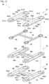
- FIG. 11 is an exploded view of the configuration of a load detection sensor according to the fourth embodiment.
- FIG. 12 is a view of the load detection sensor in plan view from the second electrode sheet side.
- the load detection sensor 5D according to the present embodiment includes a first electrode sheet 66, a second electrode sheet 67, a spacer 68, a plurality of annular members 9A to 9D, a communication member 80, and adhesive layers 10 as main constituent elements. Note that, for convenience, the adhesive layers 10 are omitted in FIG. 11 .
- the second electrode sheet 67 includes a second insulating sheet 67s and a plurality of second electrodes 67e1 to 67e4.
- the second insulating sheet 67s has an air outlet 67op penetrating from one face side to the other face side of the second insulating sheet 67s.
- the air outlet 67op that is an opening for deflation of the air in the openings of the annular members 9A to 9D to the outside of the load detection sensor 5D, is provided at a position the second electrodes 67e1 to 67e4 do not overlap in a case where the sheet face of the second electrode sheet 67 is viewed in plan view.
- the air outlet 67op is provided at the coupling block B3.
- Examples of resin as the material of the spacer 68 include PET, PI, and PEN, similarly to the first insulating sheet 66s and the second insulating sheet 67s.
- the spacer 68 may be identical in material to or different in material from the first insulating sheet 66s or the second insulating sheet 67s.
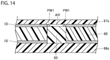
- the air inside the annular member 9A in the openings 68A to 68D of the spacer 68 flows in the air discharge slit 67s1 of the second electrode 67e1. Then, the air flows into the respective gaps AR between the pairs of wires PW1 and PW3 formed by the communicating-passage formation member 85, and discharges from the air outlet 67op to the outside of the load detection sensor through the gaps AR.
- the first electrode 111 is provided on the end side of the main block 110m.
- the first electrode 111 includes a conductive layer, for example, a metallic printed layer.
- the first electrode 111 according to the present embodiment includes a substantially-circular central electrode portion 111p and a substantially-circular ring-shaped outer electrode portion 111r surrounding the outer circumference of the central electrode portion 111p, with a gap Ills formed between the central electrode portion 111p and the outer electrode portion 111r.
- the first terminal 113 includes a conductive layer, for example, a substantially-quadrangular metallic layer.
- the first terminal 113 is provided at the tail block 110t.
- the first electrode 111 and the first terminal 113 are mutually electrically connected through the first wire 112.
- the opening 112h of the first conductive layer 110e overlaps the air outlet 110h of the first insulating sheet 110s. That is the ring portion 112r of the first wire 112 surrounds the air outlet 110h of the first insulating sheet 110s in plan view of the first electrode sheet 110.
- the engagement member 140 is a member that engages with the opening 130h of the spacer 130.
- the engagement member 140 includes an annular member 141 and a communicating-passage formation member 142 connected to the annular member 141, the annular member 141 and the communicating-passage formation member 142 being integrally formed.
- the annular member 141 is formed in a ring shape, and an opening 140h is surrounded by the annular member 141.
- the annular member 141 is circular in outer shape, similarly to the first opening portion 131 of the opening 130h.
- the outer diameter thereof is slightly smaller than the diameter of the first opening portion 131 so that the annular member 141 can engage with the first opening portion 131.
- the inner diameter of the annular member 141 is larger than the central electrode portion 111p of the first electrode 111 and the central electrode portion 121p of the second electrode 121.
- the communicating-passage formation member 142 is substantially identical in shape to the second opening portion 132 in the opening 130h of the spacer 130. Note that the communicating-passage formation member 142 is formed slightly smaller than the second opening portion 132 so that the communicating-passage formation member 142 can engage with the second opening portion 132.
- Examples of the material of the engagement member 140 are similar to the examples of the material of the first insulating sheet 110s, the examples of the material of the second insulating sheet 120s, and the examples of the material of the spacer 130.
- the engagement member 140 may be identical in material to or different in material from the spacer 130, the first insulating sheet 110s, and the second insulating sheet 120s.
- the spacer 130 and the engagement member 140 are preferably identical in material in order to reduce a relative variation due to expansion of the spacer 130 between the height of the spacer 130 and the height of the engagement member 140.
- No adhesive layer is disposed on each face of the engagement member 140.
- the central electrode portion 111p of the first electrode 111 and the central electrode portion 121p of the second electrode 121 are located inside the opening 140h of the annular member 141.
- the portion including the pair of wires, in the first wire 112 of the first electrode sheet 110 is in contact with the communicating-passage formation member 142, up to the ring portion 112r. Therefore, similarly to the fifth embodiment, according to the present embodiment, an air channel is formed by the pair of wires of the first wire 112, the first insulating sheet 110s, and the communicating-passage formation member 142.
- the annular member is in contact with both of the first electrode sheet and the second electrode sheet, but may be in contact with either the first electrode sheet or the second electrode sheet. In other words, the annular member requires contact with at least one of the first electrode sheet and the second electrode sheet.
- a load detection sensor according to Comparative Example 1, a load detection sensor according to Example 1, and a load detection sensor according to Example 2 were prepared, and experiments were conducted in applying load to each load detection sensor under different temperature environments.
- An adhesive layer on the first insulating sheet side was an acrylic adhesive layer with a thickness of 25 ⁇ m
- an adhesive layer on the second insulating sheet side was an acrylic adhesive layer with a thickness of 25 ⁇ m.
- the load detection sensor according to Comparative Example 1 and the load detection sensor according to Example 1 each had a sheet including PET with a thickness of 100 ⁇ m as a second insulating sheet.
- the load detection sensor according to Example 1 and the load detection sensor according to Example 2 each had a sheet including SUS301 with a thickness of 0.1 mm as a metallic plate and an acrylic adhesive layer with a thickness of 24 ⁇ m as an adhesive layer between the metallic plate and the insulating sheet.
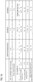
- FIG. 16 indicates the diameter of the spacer of each of the load detection sensor according to Comparative Example 1, the load detection sensor according to Example 1, and the load detection sensor according to Example 2, and the inner diameter and the material of the annular member of each of the load detection sensor according to Example 1 and the load detection sensor according to Example 2.
- the spacer opening diameter indicated in FIG. 16 means the diameter of the spacer
- the ring diameter indicated in FIG. 16 means the inner diameter of the annular member
- the ring material indicated in FIG. 16 means the material of the annular member.
- a load being applied on-load
- FIG. 16 the increase and decrease of the on-load measured under the temperature environment at -40°C and the on-load measured under the temperature environment at 85°C to the on-load measured under the temperature environment at 25°C, are indicated on a percentage basis.
- Example 1 and Example 2 in which the annular member was provided are smaller in on-load variation at the temperatures than Comparative Example 1 in which no annular member was provided. That is, it was found that provision of the annular member enables load detection equivalent to that under the ordinary temperature environment even when variation occurs from the ordinary temperature to high temperature or low temperature.
- the load detection sensor according to Comparative Example 1, the load detection sensor according to Example 1, and the load detection sensor according to Example 2 each were disposed under a temperature environment at 80°C, and then each load sensor was pressed from the second electrode sheet side by a pressure of 20 N for 144 hours. After that, on-load was measured at ordinary temperature, and the rate of change to on-load measured at ordinary temperature before the pressing was acquired as the rate of on-load change after a high-temperature constant-load test. This result is indicated in FIG. 16
- a load detection sensor according to Comparative Example 2 and a load detection sensor according to Example 3 were prepared, and then experiments were conducted in applying load to each load detection sensor under different temperature environments.
- the load detection sensor according to Comparative Example 2 and the load detection sensor according to Example 3 each had a sheet including PET with a thickness of 100 ⁇ m as a first insulating sheet and a sheet including PET with a thickness of 50 ⁇ m as a spacer.
- the load detection sensor according to Comparative Example 2 and the load detection sensor according to Example 3 each had an acrylic adhesive layer with a thickness of 25 ⁇ m as an adhesive layer on the first insulating sheet side and an acrylic adhesive layer with a thickness of 25 ⁇ m as an adhesive layer on the second insulating sheet side.
- the load detection sensor according to Comparative Example 2 and the load detection sensor according to Example 3 each had a sheet including PET with a thickness of 100 ⁇ m as a second insulating sheet.
Landscapes
- Push-Button Switches (AREA)
- Chair Legs, Seat Parts, And Backrests (AREA)
- Seats For Vehicles (AREA)
Abstract
Description
- The present invention relates to a load detection sensor suitable for detection of a load due to, for example, seating.
- As a safety system in a vehicle, an alarm system for warning that a seat belt has not been fastened at boarding, has been commercially practical. In the alarm system, a warning is issued in a case where it is not sensed that a seat belt has been fastened, with person's seating sensed. As a device that senses seating of a person, a load detection sensor that detects a load due to seating, is used in some cases.
-
Patent Literature 1 discloses a load detection sensor including: a pair of resin films; and a pair of electrodes provided on the pair of resin films, respectively, the pair of electrodes being opposed to each other at a predetermined interval. The pair of films of the load detection sensor described inPatent Literature 1 bonds together through glue disposed outside between the mutually opposed electrodes. - [Patent Literature 1] JPH09-315199 A
- However, generally, such glue tends to soften due to a rise in temperature. Therefore, in a case where the load detection sensor described in
Patent Literature 1 is subjected to a high-temperature environment, such as the inside of a motor vehicle under a blazing sun, there is concern that a drop occurs in the load necessary for contact between the respective electrodes provided at the films. Meanwhile, in a case where the load detection sensor described inPatent Literature 1 is subjected to a low-temperature environment at approximately -40°C, there is concern that a rise occurs in the load necessary for contact between the respective electrodes provided at the films due to hardening of the glue. - In some cases, long-term pressing causes such glue to be creep-deformed. Creep deformation of the glue varies the distance between the resin films, and thus there is concern that a variation occurs in the load necessary for contact between the respective electrodes provided at the films.
- Thus, according to the load detection sensor in
Patent Literature 1, the load necessary for contact between the electrodes provided at the films varies along with a variation in temperature or a variation in age, and thus there is a possibility that a proper load cannot be detected. - Therefore, an object of the present invention is to provide a load detection sensor capable of detecting a load properly.
- In order to solve the problems, a load detection sensor according to the present invention includes: a first electrode sheet including a first electrode; a second electrode sheet including a second electrode opposed to the first electrode; a spacer interposed between the first electrode sheet and the second electrode sheet, the spacer having an opening between the first electrode and the second electrode; an annular member disposed in the opening; and an adhesive layer disposed at least either between the spacer and the first electrode sheet or between the spacer and the second electrode sheet, in which the annular member is in contact with at least one of the first electrode sheet exposed at the opening and the second electrode sheet exposed at the opening, and has no adhesion to both of the first electrode sheet and the second electrode sheet.
- In the load detection sensor, the first electrode sheet exposed at the opening of the spacer and the second electrode sheet exposed at the opening of the spacer are supported by the annular member disposed in the opening. The annular member has no adhesion to both of the first electrode sheet exposed at the opening of the spacer and the second electrode sheet exposed at the opening of the spacer. Thus, in comparison to a case where the annular member adheres to at least one of the first electrode sheet and the second electrode sheet through an adhesive layer, there is no influence of the adhesive layer due to a variation in temperature.
- That is the adhesive layer tends to soften under a high-temperature environment and tends to harden under a low-temperature environment, easily. Thus, in a case where no annular member is provided, variation of the adhesive layer at the edge portion of the opening of the spacer, corresponding to a temperature environment, causes a variation in the degree of inward deflection to the opening of the spacer between the first electrode sheet and the second electrode sheet. The variation in the degree of deflection causes a variation in the load necessary for contact between the first electrode and the second electrode. In contrast to this, because the annular member disposed in the opening of the spacer has no adhesion to both of the first electrode sheet and the second electrode sheet, a variation in temperature environment due to the adhesive layer does not occur at the edge portion of the opening of the annular member. Thus, the degree of inward deflection inside the annular member in the opening of the spacer due to pressing of at least one of the first electrode sheet and the second electrode sheet, substantially does not change. Thus, in comparison to a case where the annular member adheres to at least one of the first electrode sheet and the second electrode sheet through an adhesive layer, the load necessary for contact between the first electrode and the second electrode can be prevented from varying.
- The presence of the annular member causes less load to be applied to the adhesive layer, and thus the adhesive layer is less likely to be creep-deformed. Even if the adhesive layer is creep-deformed by long-term pressing of the load detection sensor, the distance between the first electrode sheet and the second electrode sheet is substantially constantly retained by the annular member. As a result, variation in the load necessary for contact between the first electrode and the second electrode along with creep deformation, is reduced.
- Thus, the load detection sensor capable of detecting a load properly, is achieved.
- Preferably, the annular member is in contact with both of the first electrode sheet and the second electrode sheet.
- In this case, because there is no gap between the first electrode sheet exposed at the opening of the spacer, the second electrode sheet exposed at the opening of the spacer, and the annular member, the annular member can support the first electrode sheet and the second electrode sheet, more stably. Therefore, variation in the load necessary for contact between the first electrode and the second electrode, can be further reduced.
- Preferably, at least part of an outer circumferential face of the annular member is spaced apart from the spacer.
- Even when the adhesive layer disposed at least either between the spacer and the first electrode sheet or between the spacer and the second electrode sheet softens and flows into the opening side due to the load detection sensor under a high-temperature environment, the adhesive layer can be stored in the gap between the annular member and the spacer. Therefore, flowing of the softened adhesive layer between the annular member and the first electrode sheet or the second electrode sheet, is avoided. As a result, variation in the load necessary for contact between the first electrode and the second electrode, can be further reduced.
- Preferably, the annular member is identical in material to the spacer.
- In this case, the annular member is approximately equivalent in expansion due to the load detection sensor under a high-temperature environment, to the spacer. Thus, the distance between the first electrode sheet and the second electrode sheet is substantially constantly retained. Therefore, variation of the inter-electrode distance due to thermal expansion is reduced. As a result, variation in load can be further reduced.
- Preferably, the annular member has a vent for deflation of air in the opening of the spacer.
- In this case, when inward deflection of the first electrode sheet or the second electrode sheet inside the annular member in the opening of the spacer causes contact between the first electrode and the second electrode, the air in the opening of the spacer discharges from the vent. Therefore, inhibition of deflection of the second electrode sheet due to the air in the opening of the spacer, is avoided, so that the load detection sensor can be prevented from performing false detection.
- Preferably, the spacer has a slit connected to the opening, at least one of the first electrode sheet and the second electrode sheet has an air outlet, and a communication member is disposed in the slit, the communication member allowing communication between the vent of the annular member and the air outlet.
- In this case, when inward deflection of the first electrode sheet or the second electrode sheet inside the annular member in the opening of the spacer causes contact between the first electrode and the second electrode, the air in the opening of the spacer discharges from the air outlet to the outside of the load detection sensor through the communication member. Therefore, inhibition of deflection of the first electrode sheet or the second electrode sheet due to the air in the opening of the spacer, is avoided, so that the load detection sensor can be prevented from performing false detection.
- Preferably, the spacer has a slit connected to the opening, at least one of the first electrode sheet and the second electrode sheet includes a pair of wires mutually adjacently spaced part and an air outlet, an end of the pair of wires is located inside the annular member, and a communicating-passage formation member is disposed in the slit, the communicating-passage formation member forming a gap between the pair of wires as a communicating passage allowing communication between an inside of the annular member in the opening of the spacer and the air outlet.
- In this case, when inward deflection of at least one of the first electrode sheet and the second electrode sheet inside the annular member in the opening of the spacer causes contact between the first electrode and the second electrode, the air inside the annular member in the opening of the spacer discharges from the air outlet to the outside of the load detection sensor through the gap between the pair of wires formed by the communicating-passage formation member. Therefore, inhibition of deflection of the first electrode sheet or the second electrode sheet due to the air inside the annular member, is avoided, so that the load detection sensor can be prevented from performing false detection due to the inhibition of electrode-sheet deflection due to the air.
- Preferably, in a case where a sheet face of the first electrode sheet is viewed in plan view, the annular member overlaps the first electrode and the second electrode.
- In this case, the annular member is interposed between the first electrode and the second electrode. Thus, even when the first electrode itself and the second electrode itself each have variation in thickness, the distance between the first electrode and the second electrode is substantially constantly retained by the annular member. Therefore, the variation in distance between the first electrode and the second electrode between a plurality of load detection sensors can be reduced by the annular member, so that the variation in the load necessary for contact between the first electrode and the second electrode between the load detection sensors is reduced.
- Preferably, a sum of a thickness of the spacer and a thickness of the adhesive layer is approximately equivalent to a sum of a height of the annular member, a thickness of the first electrode, and a thickness of the second electrode.
- In this case, even when the annular member has no adhesion to the first electrode sheet and the second electrode sheet, the annular member is inhibited from moving in the opening of the spacer. Under no load in which no load is applied to the load detection sensor, stress can be prevented from occurring in a direction in which the spacer and the electrode sheet adhering through the adhesive layer peel off.
- Preferably, in a case where a sheet face of the first electrode sheet is viewed in plan view, the annular member does not overlap the first electrode and the second electrode.
- In this case, the first electrode and the second electrode can be less damaged in comparison to a case where the annular member overlaps the first electrode and the second electrode.
- Preferably, a sum of a thickness of the spacer and a thickness of the adhesive layer is approximately equivalent to a height of the annular member.
- In this case, even when the annular member has no adhesion to the first insulating sheet and the second insulating sheet, the annular member is inhibited from moving in the opening of the spacer. Under no load in which no load is applied to the load detection sensor, stress can be prevented from occurring in a direction in which the spacer and the electrode sheet adhering through the adhesive layer peel off.
- According to the present invention described above, the load detection sensor capable of detecting a load properly, can be provided.
-
-
FIG. 1 is an exploded view of the configuration of a load detection sensor according to a first embodiment. -
FIG. 2 is a sectional view of the configuration of the load detection sensor. -
FIG. 3 is a view of the ON state of the load detection sensor. -
FIG. 4 is an exploded view of the configuration of a load detection sensor unit according to a second embodiment. -
FIG. 5 is a sectional view of the load detection sensor unit attached to S-shaped springs of a seat device. -
FIG. 6 is an exploded view of a load detection sensor according to the second embodiment. -
FIG. 7 is a sectional view of the load detection sensor according to the second embodiment. -
FIG. 8 is a view of a sheet face of a first electrode sheet of the load detection sensor in plan view. -
FIG. 9 is a view of the ON state of the load detection sensor unit. -
FIG. 10 is a sectional view of a load detection sensor according to a third embodiment. -
FIG. 11 is an exploded view of the configuration of a load detection sensor according to a fourth embodiment. -
FIG. 12 is a view of the load detection sensor in plan view from the second electrode sheet side. -
FIG. 13 is an exploded view of the configuration of a load detection sensor according to a fifth embodiment. -
FIG. 14 is a sectional view of the load detection sensor taken along line X-X ofFIG. 13 . -
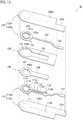
FIG. 15 is an exploded view of the configuration of a load detection sensor according to a sixth embodiment. -
FIG. 16 is a table of part of experimental conditions and experimental results. -
FIG. 17 is a table of part of other experimental conditions and experimental results. - Preferred embodiments of a load detection sensor unit according to the present invention, will be described in detail below with reference to the drawings. Note that, for ease in understanding, in some cases, the respective scales of the figures are different from the scales described in the following description.
-
FIG. 1 is an exploded view of the configuration of a load detection sensor according to a first embodiment.FIG. 2 is a sectional view of the configuration of the load detection sensor. As illustrated inFIGS. 1 and2 , theload detection sensor 5A includes afirst electrode sheet 6, asecond electrode sheet 7, aspacer 8, anannular member 9, andadhesive layers 10 as main constituent elements. Note that, for convenience, theadhesive layers 10 are omitted inFIG. 1 . - The
first electrode sheet 6 includes a first insulatingsheet 61 and afirst electrode 62. The first insulatingsheet 61 is a resin insulating sheet having flexibility. Examples of reins as the material of the first insulatingsheet 61 include polyethylene terephthalate (PET), polyimide (PI), and polyethylene naphthalate (PEN). - The
first electrode 62 that is one switch element included in a switch SW in theload detection sensor 5A (FIG. 2 ), includes, for example, a substantially-circular metallic printed layer. Thefirst electrode 62 disposed on one surface of the first insulatingsheet 61, is electrically connected to one terminal of a pair of terminals through afirst wire 63. - The
second electrode sheet 7 includes a second insulatingsheet 71 and asecond electrode 72. The second insulatingsheet 71 disposed on the pressing portion PP (FIG. 2 ) side with respect to thefirst electrode sheet 6, is a film-shaped insulating sheet having flexibility. The pressing portion PP for pressing the switch SW of theload detection sensor 5A (FIG. 2 ), is secured to, for example, a member different from theload detection sensor 5A. Referring toFIG. 2 , the leading end of the pressing portion PP has a flat shape, but may have a protruding curved shape. The leading end of the pressing portion PP is usually in no-contact with the second insulatingsheet 71 of thesecond electrode sheet 7, but may be in contact with the second insulatingsheet 71. Similarly to the first insulatingsheet 61, examples of resins as the material of the second insulatingsheet 71 include PET, PI, and PEN. The second insulatingsheet 71 may be identical in material to or different in material from the first insulatingsheet 61. - The
second electrode 72 that is the other switch element included in the switch SW of theload detection sensor 5A (FIG. 2 ), includes, for example, a substantially-circular metallic printed layer. Thesecond electrode 72 disposed on one surface of the second insulatingsheet 71, is electrically connected to the other terminal of the pair of terminals through asecond wire 73. Note that, according to the present embodiment, thesecond electrode 72 is identical in size to thefirst electrode 62. - The
spacer 8 interposed between thefirst electrode sheet 6 and thesecond electrode sheet 7, includes a resin insulating sheet having flexibility. Similarly to the first insulatingsheet 61 and the second insulatingsheet 71, examples of resins as the material of thespacer 8 include PET, PI, and PEN. Note that thespacer 8 may be identical in material to or different in material from the first insulatingsheet 61 or the second insulatingsheet 71. - The
spacer 8 has anopening 81 penetrating from one face side to the other face side of thespacer 8. The circumferential-edge shape of theopening 81 is, for example, substantially circular. Theopening 81 is formed larger in diameter than thefirst electrode 62 and thesecond electrode 72. - Furthermore, the
spacer 8 has aslit 82 allowing communication between the space in theopening 81 and the external space of theload detection sensor 5A. Theslit 82 serves as an air vent with thespacer 8 superimposed on thefirst electrode sheet 6 and thesecond electrode sheet 7. The air vent is a passage for deflation of the air in theopening 81 to the outside of theload detection sensor 5A. - The
annular member 9 is a member in an annular shape disposed in theopening 81 of thespacer 8. The outer diameter of theannular member 9 is smaller than the diameter of theopening 81 of thespacer 8, and the inner diameter of theannular member 9 is larger than the diameters of thefirst electrode 62 and thesecond electrode 72. The height of theannular member 9 is approximately equivalent to the sum of the thickness of theadhesive layer 10 between the first insulatingsheet 61 and thespacer 8, the thickness of theadhesive layer 10 between the second insulatingsheet 71 and thespacer 8, and the thickness of thespacer 8. Note that, for theannular member 9, in a case where a sheet face of thefirst electrode sheet 6 is viewed in plan view in plan view, theannular member 9 does not overlap thefirst electrode 62 and thesecond electrode 72. - Similarly to the first insulating
sheet 61, the second insulatingsheet 71, and thespacer 8, examples of resins as the material of theannular member 9 include PET, PI, and PEN. Note that theannular member 9 may be identical in material to or different in material from thespacer 8, the first insulatingsheet 61, or the second insulatingsheet 71. Note that thespacer 8 and theannular member 9 are preferably identical in material in order to reduce a variation due to expansion between the height of theannular member 9 and the height of thespacer 8 and the adhesive layers 10. - The
annular member 9 has avent 91 for deflation of the air inside theannular member 9, namely, in the opening of theannular member 9 in theopening 81 of thespacer 8. According to the present embodiment, thevent 91 is a slit formed from one end to the other end in the height direction of theannular member 9, but may be a through hole penetrating from the outer circumferential face to the inner circumferential face of the annular member. Note that theannular member 9 according to the present embodiment has a break at part in the circumferential direction of theannular member 9 due to thevent 91. The length of the break in the circumferential direction of theannular member 9, is preferably not more than one fifth of the entire length in the circumferential direction of theannular member 9 including the break. According to the present embodiment, one break is provided, but a plurality of breaks may be provided. Note that, in a case where a plurality of breaks is provided, the sum of the lengths of the breaks in the circumferential direction of theannular member 9 is preferably not more than one third of the entire length in the circumferential direction of theannular member 9 including the plurality of breaks. Thus, as long as a ring-like shape exists, theannular member 9 includes one break or intermittent breaks. Note that, from the viewpoint of inhibition of the man-hour for assembly from increasing due to division of theannular member 9 into a plurality of members or from the viewpoint of inhibition of a variation in load due to the annular member deviated in arrangement by, for example, vibration due to division of theannular member 9 into a plurality of members, preferably, the number of breaks is one or less. - The respective
adhesive layers 10 are disposed between the first insulatingsheet 61 of thefirst electrode sheet 6 and thespacer 8 and between the second insulatingsheet 71 of thesecond electrode sheet 7 and thespacer 8. The adhesive layers 10 are not particularly limited as long as the first insulatingsheet 61, the second insulatingsheet 71, and thespacer 8 bond together. Examples of theadhesive layers 10 include glue, adhesive, and double-sided tape including a base material, such as PET or nonwoven fabric, having each face provided with glue or adhesive. Examples of the material of theadhesive layers 10 include thermoplastic resin, thermosetting resin, and photo-curable resin. Note that examples of the glue include silicon glue, urethane glue, and acrylic glue. The respectiveadhesive layers 10 may be disposed over the entire faces between the first insulatingsheet 61 and thespacer 8 and over the entire faces between the second insulatingsheet 71 and thespacer 8. Alternatively, the respectiveadhesive layers 10 may be dispersedly disposed at a plurality of portions between the first insulatingsheet 61 and thespacer 8 and at a plurality of portions between the second insulatingsheet 71 and thespacer 8. Theannular member 9 is preferably larger in elastic modulus than the adhesive layers 10. - The
load detection sensor 5A includes the above constituent elements in combination. That is theload detection sensor 5A includes thefirst electrode sheet 6 adhering on the one face side of thespacer 8 through theadhesive layer 10 and thesecond electrode sheet 7 adhering on the other face side of thespacer 8 through theadhesive layer 10 with theannular member 9 disposed in theopening 81 of thespacer 8. - In the
load detection sensor 5A, theannular member 9 is in contact with both of the first insulatingsheet 61 exposed on one opening face side of theopening 81 of thespacer 8 and the second insulatingsheet 71 exposed on the other opening face side of theopening 81. Specifically, one end of theannular member 9 is in contact with the inner circumferential portion exposed from theopening 81, in the first insulatingsheet 61, and the other end of theannular member 9 is in contact with the inner circumferential portion exposed from theopening 81, in the second insulatingsheet 71. Therefore, theannular member 9 can support the inner circumferential portion exposed from theopening 81, in the first insulatingsheet 61 and the inner circumferential portion exposed from theopening 81, in the second insulatingsheet 71. Note that theannular member 9 has no adhesion to both of the first insulatingsheet 61 exposed on the one opening face side of theopening 81 of thespacer 8 and the second insulatingsheet 71 exposed on the other opening face side of theopening 81. - In the
load detection sensor 5A, thevent 91 of theannular member 9 is in communication with the outside of theload detection sensor 5A through theslit 82 of thespacer 8, with the outer circumferential face of theannular member 9 disposed apart from thespacer 8. Note that only part of the outer circumferential face of theannular member 9 may be in contact with thespacer 8. That is the outer circumferential face of theannular member 9 requires at least spacing apart from part of thespacer 8. - Furthermore, in the
load detection sensor 5A, thefirst electrode 62 is located inside one opening end in theannular member 9, and thesecond electrode 72 is located inside the other opening end in theannular member 9. Thefirst electrode 62 and thesecond electrode 72 opposed to each other inside theannular member 9, are included in the switch SW. - Next, detection of a load by the
load detection sensor 5A according to the present embodiment, will be described. -
FIG. 3 is a view of the ON state of theload detection sensor 5A. Downward movement of the pressing portion PP due to reception of a load, causes contact with the face opposite to the face on thespacer 8 side of the second insulatingsheet 71 of thesecond electrode sheet 7, resulting in pressing of the second insulatingsheet 71. Inward deflection of the second insulatingsheet 71 inside theannular member 9 due to the press of the pressing portion PP, causes thesecond electrode 72 in contact with thefirst electrode 62, so that the switch SW of theload detection sensor 5A changes to the ON state. In this case, the load is detected by a vehicular control unit, not illustrated, electrically connected to thesecond electrode 72 and thefirst electrode 62. - Note that deflection of the second insulating
sheet 71 causes the air inside theannular member 9 to discharge outside theannular member 9 through thevent 91 of theannular member 9 and causes the air in theopening 81 of thespacer 8 to discharge through theslit 82. Therefore, inhibition of deflection between the first insulatingsheet 61 and the second insulatingsheet 71 due to the air inside theannular member 9 and the air in theopening 81 of thespacer 8, is avoided, so that the switch SW of theload detection sensor 5A changes to the ON state, properly. - As described above, the
load detection sensor 5A according to the present embodiment includes: thefirst electrode sheet 6 including thefirst electrode 62; thesecond electrode sheet 7 including thesecond electrode 72 opposed to thefirst electrode 62; and thespacer 8 interposed between thefirst electrode sheet 6 and thesecond electrode sheet 7, thespacer 8 having theopening 81 between thefirst electrode 62 and thesecond electrode 72. Theload detection sensor 5A includes: theannular member 9 disposed in theopening 81 of thespacer 8; and the respectiveadhesive layers 10 disposed between thespacer 8 and thefirst electrode sheet 6 and between thespacer 8 and thesecond electrode sheet 7. - In the
load detection sensor 5A, because theannular member 9 is disposed in theopening 81 of thespacer 8, theannular member 9 supports the inner circumferential portion exposed from theopening 81 of thefirst electrode sheet 6 and the inner circumferential portion exposed from theopening 81 of thesecond electrode sheet 7. Theannular member 9 has no adhesion to both of thefirst electrode sheet 6 exposed at theopening 81 of thespacer 8 and thesecond electrode sheet 7 exposed at theopening 81 of thespacer 8. - Thus, in comparison to a case where the
annular member 9 adheres to at least one of thefirst electrode sheet 6 and thesecond electrode sheet 7 through anadhesive layer 10, there is no influence of the adhesive layer due to a variation in temperature. - That is the
adhesive layer 10 tends to soften under a high-temperature environment and tends to harden under a low-temperature environment, easily. Thus, in a case where noannular member 9 is provided, variation of theadhesive layers 10 at the edge portion of theopening 81 of thespacer 8, corresponding to a temperature environment, causes a variation in the degree of inward deflection to theopening 81 of thespacer 8 between thefirst electrode sheet 6 and thesecond electrode sheet 7. The variation in the degree of deflection causes a variation in the load necessary for contact between thefirst electrode 62 and thesecond electrode 72. In contrast to this, according to the present embodiment, because theannular member 9 disposed in theopening 81 of thespacer 8 has no adhesion, a variation in temperature environment due to theadhesive layers 10 does not occur at the edge portion of the opening of theannular member 9. Thus, the degree of inward deflection inside theannular member 9 due to pressing of thesecond electrode sheet 7, substantially does not change. Therefore, in comparison to a case where theannular member 9 adheres to at least one of thefirst electrode sheet 6 and thesecond electrode sheet 7 through an adhesive layer, the load necessary for contact between thefirst electrode 62 and thesecond electrode 72 can be prevented from varying. - The presence of the
annular member 9 causes less load to be applied to theadhesive layers 10, and thus theadhesive layers 10 are less likely to be creep-deformed. Even if theadhesive layers 10 are creep-deformed by long-term pressing of theload detection sensor 5A, the distance between thefirst electrode sheet 6 and thesecond electrode sheet 7 is substantially constantly retained by theannular member 9. As a result, variation in the load necessary for contact between thefirst electrode 62 and thesecond electrode 72, along with creep deformation, can be reduced. - Thus, the
load detection sensor 5A capable of detecting a load properly, is achieved. - The
annular member 9 according to the present embodiment is in contact with both of thefirst electrode sheet 6 exposed at theopening 81 of thespacer 8 and thesecond electrode sheet 7 exposed at theopening 81 of thespacer 8. - Thus, because there is no gap between the
first electrode sheet 6 exposed at theopening 81 of thespacer 8, thesecond electrode sheet 7 exposed at theopening 81 of thespacer 8, and theannular member 9, theannular member 9 can support thefirst electrode sheet 6 and thesecond electrode sheet 7, more stably. Therefore, variation in the load necessary for contact between thefirst electrode 62 and thesecond electrode 72, can be further reduced. - The outer circumferential face of the
annular member 9 according to the present embodiment is spaced apart from thespacer 8. Thus, even when theadhesive layer 10 between thespacer 8 and thefirst electrode sheet 6 and theadhesive layer 10 between thespacer 8 and thesecond electrode sheet 7 soften and flow into theopening 81 due to theload detection sensor 5A under a high-temperature environment, theadhesive layers 10 can be stored in the gap between theannular member 9 and thespacer 8. Therefore, flowing of the softenedadhesive layers 10 between theannular member 9, thefirst electrode sheet 6, and thesecond electrode sheet 7, can be avoided. As a result, variation in the load necessary for contact between thefirst electrode 62 and thesecond electrode 72, can be further reduced. - The
annular member 9 according to the present embodiment has thevent 91 for deflation of the air inside theannular member 9 in theopening 81 of thespacer 8. Thus, when inward deflection of thesecond electrode sheet 7 inside theannular member 9 causes contact between thefirst electrode 62 and thesecond electrode 72, the air inside theannular member 9 discharges from thevent 91. Therefore, inhibition of deflection of thesecond electrode sheet 7 due to the air inside theannular member 9 is avoided, so that the load detection sensor can be prevented from performing false detection. - Note that, in a case where the
annular member 9 and thespacer 8 are identical in material, the expansion of theannular member 9 and the expansion of thespacer 8 due to theload detection sensor 5A under a high-temperature environment, are approximately equivalent. Thus, the distance between thefirst electrode sheet 6 and thesecond electrode sheet 7 is substantially constantly retained. Therefore, in a case where theannular member 9 and thespacer 8 are identical in material, variation of the inter-electrode distance due to thermal expansion is reduced. As a result, variation in load can be further reduced. - For the
annular member 9, in a case where the sheet face of thefirst electrode sheet 6 is viewed in plan view, theannular member 9 does not overlap thefirst electrode 62 and thesecond electrode 72. This arrangement enables thefirst electrode 62 and thesecond electrode 72 to be less damaged in comparison to a case where theannular member 9 overlaps thefirst electrode 62 and thesecond electrode 72. - The height of the
annular member 9 is approximately equivalent to the sum of the thickness of theadhesive layer 10 between the first insulatingsheet 61 and thespacer 8, the thickness of theadhesive layer 10 between the second insulatingsheet 71 and thespacer 8, and the thickness of thespacer 8. - In this case, even when the
annular member 9 has no adhesion to the first insulatingsheet 61 and the second insulatingsheet 71, theannular member 9 is inhibited from moving in theopening 81 of thespacer 8. Under no load in which no load is applied to theload detection sensor 5A, stress can be prevented from occurring in a direction in which the spacer and each electrode sheet adhering through theadhesive layer 10 peel off. - Next, a load detection sensor unit will be described as a second embodiment. Note that configurations similar to the configurations described above are denoted with the same reference signs. Unless otherwise specified, the duplicate descriptions will be omitted.
-
FIG. 4 is an exploded view of the configuration of the load detection sensor unit according to the second embodiment.FIG. 5 is a sectional view of the load detection sensor unit attached to S-shaped springs of a seat device. Note that, for convenience, aload detection sensor 5B is not illustrated in section inFIG. 5 . As illustrated inFIGS. 4 and5 , the loaddetection sensor unit 100 includes asupport plate 2, anupper case 4, and theload detection sensor 5B as main constituent elements. - The
support plate 2 includes amount portion 21 on which theload detection sensor 5B is mounted, and a pair ofhook portions 22 coupled to themount portion 21. Themount portion 21 includes: a wide mainblock mount portion 21m; and a tailblock mount portion 21t extending from the mainblock mount portion 21m, the tailblock mount portion 21t being narrower in width than the mainblock mount portion 21m. According to the present embodiment, thehook portions 22 are coupled to the mainblock mount portion 21m. According to the present embodiment, themount portion 21 and the pair ofhook portions 22 are integrally formed by bending of a metallic plate. Note that the plate thickness of thesupport plate 2 is, for example, 0.8 mm. - A
main block 50m in theload detection sensor 5B is disposed on a face of the mainblock mount portion 21m, the face being opposed to a seat cushion SC. As illustrated inFIG. 4 , the mainblock mount portion 21m has a plurality of circular throughholes 20H penetrating through thesupport plate 2, and further has a plurality of substantially-rectangular case-lockingopenings 24. - Note that, as illustrated in
FIG. 5 , the mainblock mount portion 21m has a degree of size so as to be disposed between two mutually opposed S-shaped springs BN from a plurality of S-shaped springs BN stretched alongside across the opening of a seat frame in the vehicular seat device. Note that the S-shaped springs BN each are a spring serpentine in an S shape. - The tail
block mount portion 21t having a substantially rectangular shape, extends in a direction substantially perpendicular to a direction passing through the pair ofhook portions 22 in plan view of the mainblock mount portion 21m. Atail block 50t in theload detection sensor 5B is disposed on a face of the tailblock mount portion 21t, the face being opposed to the seat cushion SC. Note that, according to the present embodiment, the width in a direction perpendicular to the extending direction of the tailblock mount portion 21t is smaller than the width of thetail block 50t of theload detection sensor 5B, and the length in the extending direction of the tailblock mount portion 21t is smaller than the length of thetail block 50t of theload detection sensor 5B. - The
upper case 4 is a member covering themain block 50m mounted on the mainblock mount portion 21m of themount portion 21 such that, for example, a switch SW in themain block 50m is protected. As illustrated inFIG. 5 , theupper case 4 doubles as a pressing member that presses the switch SW of theload detection sensor 5B by pressing from the seat cushion SC. - The
upper case 4 includes atop wall 45 and aframe wall 48. According to the present embodiment, thetop wall 45 is a tabular member that is substantially rectangular. Theframe wall 48 of theupper case 4 includes a plurality of divided portions connected to thetop wall 45 in the outer circumference of thetop wall 45. Ahook piece 47 is connected to thetop wall 45 between each of the plurality of divided portions of theframe wall 48. Thehook pieces 47 individually engage with the case-lockingopenings 24 at the mainblock mount portion 21m of thesupport plate 2. Individual engagement of thehook pieces 47 with the case-lockingopenings 24 regulates the relative movement in the mount in-plane direction of the mainblock mount portion 21m between thesupport plate 2 and theupper case 4. - The
top wall 45 of theupper case 4 has a bottom face from which apressing portion 46 protrudes, the bottom face being opposed to themount portion 21 of thesupport plate 2. The leading end of thepressing portion 46 has a flat shape. Note that the leading end of thepressing portion 46 may have a protruding curved shape. According to the present embodiment, with theupper case 4 covering theload detection sensor 5B mounted on themount portion 21 and thehook pieces 47 engaging with the corresponding case-lockingopenings 24, the leading end of thepressing portion 46 is in contact with theload detection sensor 5B, but is not necessarily in contact with theload detection sensor 5B. - As illustrated in
FIG. 5 , with the loaddetection sensor unit 100 attached to the pair of S-shaped springs BN, theupper face 45S of thetop wall 45 of theupper case 4 is spaced apart from the lower face of the seat cushion SC, but may be in contact with the lower face of the seat cushion SC. Theupper face 45S has a flat shape. Theupper face 45S is a pressure-receiving face that receives pressing from the seat cushion SC. Theupper face 45S is larger in area than the portion in contact with the switch SW of theload detection sensor 5B, in thepressing portion 46. - Note that the
upper case 4 is formed of material harder than that of the seat cushion SC. Therefore, thepressing portion 46 that is part of theupper case 4 is formed of the material harder than that of the seat cushion SC. Because, generally, the seat cushion SC includes foamed urethane resin, examples of resin as the material of theupper case 4 include polycarbonate (PC), polybutylene terephthalate (PBT), polyamide (PA), phenolic resin, and epoxy resin. - As described above, the
load detection sensor 5B includes: themain block 50m that is substantially rectangular; and thetail block 50t connected to themain block 50m, thetail block 50t being narrower in width than themain block 50m. Themain block 50m is provided with the switch SW. A throughhole 50H is formed near each apex of themain block 50m. The throughholes 50H are formed in positional relationship so as to be superimposed on the plurality of throughholes 20H formed through themount portion 21 of thesupport plate 2. Thetail block 50t coupled to themain block 50m, extends apart from themain block 50m. -
FIG. 6 is an exploded view of the load detection sensor according to the second embodiment.FIG. 7 is a sectional view of the load detection sensor according to the second embodiment. As illustrated inFIGS. 6 and7 , theload detection sensor 5B according to the present embodiment includes afirst electrode sheet 56, asecond electrode sheet 57, aspacer 58, anannular member 59,adhesive layers 10 as main constituent elements. Note that, for convenience, theadhesive layers 10 are omitted inFIG. 6 . - The
first electrode sheet 56 includes a first insulatingsheet 56s, afirst electrode 56e, and afirst terminal 56c. - The first insulating
sheet 56s is a resin insulating sheet having flexibility. The first insulatingsheet 56s includes amain block 56m and atail block 56t connected to themain block 56m. For the shape of thetail block 56t, a leading end portion opposite to themain block 56m is narrower in width than the other portion of thetail block 56t. Themain block 56m has throughholes 56H. Note that the throughholes 56H are part of the throughholes 50H of theload detection sensor 5B. Examples of resin as the material of the first insulatingsheet 56s include PET, PI, and PEN. - The
first electrode 56e is provided at substantially the center on one face of themain block 56m. Thefirst electrode 56e includes a conductive layer, for example, a substantially-circular metallic printed layer. Thefirst terminal 56c includes a conductive layer, for example, a substantially-quadrangular metallic layer. Thefirst terminal 56c is provided on a face of the leading end portion of thetail block 56t, the face being on the side on which thefirst electrode 56e is provided. Thefirst electrode 56e and thefirst terminal 56c are mutually electrically connected through afirst wire 56w. - The
second electrode sheet 57 includes a second insulatingsheet 57s, ametallic plate 60, an adhesive layer formetal 70, asecond electrode 57e, and asecond terminal 57c. Thesecond electrode sheet 7 according to the first embodiment includes one layer of the second insulatingsheet 71, whereas thesecond electrode sheet 57 according to the present embodiment includes two layers of the second insulatingsheet 57s and themetallic plate 60. - The second insulating
sheet 57s disposed on the seat cushion SC (FIG. 4 ) side with respect to thefirst electrode sheet 56, is a resin insulating sheet, similarly to the first insulatingsheet 56s. According to the present embodiment, the second insulatingsheet 57s is smaller in thickness than the first insulatingsheet 56s, and is less in thickness than themetallic plate 60. The second insulatingsheet 57s includes: amain block 57m identical in shape to themain block 56m of the first insulatingsheet 56s; and atail block 57t connected to themain block 57m, thetail block 57t being identical in shape to thetail block 56t of the first insulatingsheet 56s except for the leading end portion. The leading end portion of thetail block 57t is narrower in width than the other portion of thetail block 57t. When the first insulatingsheet 56s and the second insulatingsheet 57s are superimposed, the leading end portion of thetail block 56t of the first insulatingsheet 56s and the leading end portion of thetail block 57t of the second insulatingsheet 57s do not overlap each other. Themain block 57m has throughholes 57H. Note that the throughholes 57H are part of the throughholes 50H of theload detection sensor 5B, similarly to the throughholes 56H of the first insulatingsheet 56s. Examples of resin as the material of the second insulatingsheet 57s include PET, PI, and PEN. The second insulatingsheet 57s may be identical in material to or different in material from the first insulatingsheet 56s. - The
metallic plate 60 bonds to one face of the second insulatingsheet 57s through the adhesive layer formetal 70. According to the present embodiment, themetallic plate 60 bonds to the face on the seat cushion SC side of themain block 57m that is part of the second insulatingsheet 57s. Themetallic plate 60 has throughholes 60H. Note that the throughholes 60H are part of the throughholes 50H of theload detection sensor 5B. Examples of the material of themetallic plate 60 include, but are not particularly limited to, copper and stainless steel. - The adhesive layer for
metal 70 is disposed between themain block 57m of the second insulatingsheet 57s and themetallic plate 60. The adhesive layer formetal 70 is not particularly limited as long as the second insulatingsheet 57s and themetallic plate 60 bond together. Examples of the adhesive layer formetal 70 include glue, adhesive, and double-sided tape including a base material, such as PET or nonwoven fabric, having each face provided with glue or adhesive. Examples of the material of the adhesive layer formetal 70 include thermoplastic resin, thermosetting resin, and photo-curable resin. Note that the adhesive layer formetal 70 may be identical in material to or different in material from the adhesive layers 10. Here, the glass-transition temperature Tg of the adhesive layer formetal 70 is preferably 85°C or more. A glass-transition temperature Tg of 85°C or more causes the adhesive layer formetal 70 to be less likely to flow even in a high-temperature environment, such as the inside of a motor vehicle under a blazing sun, so that false detection of seating due to flowing of the adhesive layer formetal 70 can be inhibited. Note that, as long as the second insulatingsheet 57s and themetallic plate 60 bond together, the adhesive layer formetal 70 may be disposed over the entire faces between the second insulatingsheet 57s and themetallic plate 60 or may be dispersedly disposed at a plurality of portions between the second insulatingsheet 57s and themetallic plate 60. - The
second electrode 57e similar in configuration to thefirst electrode 56e, is provided at substantially the center on one face of themain block 57m of the second insulatingsheet 57s. The position for provision of thesecond electrode 57e allows superimposition of thesecond electrode 57e on thefirst electrode 56e at superimposition of thefirst electrode sheet 56 and thesecond electrode sheet 57. Thesecond terminal 57c similar in configuration to thefirst terminal 56c, is provided on a face of the leading end portion of thetail block 57t, the face being on the side on which thesecond electrode 57e is provided. As described above, when the first insulatingsheet 56s and the second insulatingsheet 57s are superimposed, the respective leading end portions of the insulating sheets do not overlap each other. Thus, thefirst terminal 56c and thesecond terminal 57c are exposed without being located between the first insulatingsheet 56s and the second insulatingsheet 57s. Thesecond electrode 57e and thesecond terminal 57c are mutually electrically connected through asecond wire 57w. - The
spacer 58 disposed between thefirst electrode sheet 56 and thesecond electrode sheet 57, includes a resin insulating sheet having flexibility. Thespacer 58 includes amain block 58m and atail block 58t connected to themain block 58m. Themain block 58m is similar in outer shape to themain blocks sheet 56s and the second insulatingsheet 57s. Thetail block 58t has a shape identical to the shape in which the leading end portion narrow in width is excluded from each of the tail blocks 56t and 57t of the first insulatingsheet 56s and the second insulatingsheet 57s. Thespacer 58 has throughholes 58H, similarly to the first insulatingsheet 56s and the second insulatingsheet 57s. Note that the throughholes 58H are part of the throughholes 50H of theload detection sensor 5B. Examples of resin as the material of thespacer 58 include PET, PI, and PEN, similarly to the first insulatingsheet 56s and the second insulatingsheet 57s. Note that thespacer 58 may be identical in material to or different in material from the first insulatingsheet 56s or the second insulatingsheet 57s. - The
main block 58m of thespacer 58 has anopening 58c penetrating from one face side to the other face side of thespacer 58. Thefirst electrode 56e and thesecond electrode 57e are opposed to each other through theopening 58c. The circumferential-edge shape of theopening 58c is, for example, substantially circular. Theopening 58c is formed smaller in diameter than thefirst electrode 56e and thesecond electrode 57e. - The
opening 81 of thespacer 8 according to the first embodiment is formed larger in diameter than thefirst electrode 62 and thesecond electrode 72. In contrast to this, theopening 58c of thespacer 58 according to the present embodiment is formed smaller in diameter than thefirst electrode 56e and thesecond electrode 57e. Therefore, for theopening 58c according to the present embodiment, in a case where thespacer 58 is superimposed on thefirst electrode sheet 56 and thesecond electrode sheet 57, theopening 58c of thespacer 58 is located inside the circumferential edges of thefirst electrode 56e and thesecond electrode 57e. - Furthermore, the
spacer 58 has aslit 58b through which the space in theopening 58c is in communication with the external space of theload detection sensor 5B. Theslit 58b serves as an air vent with thefirst electrode sheet 56, thespacer 58, and thesecond electrode sheet 57 in superimposition on each other. The air vent is a passage for deflation of the air in theopening 58c to the outside of theload detection sensor 5B. - The
annular member 59 is a member in an annular shape disposed in theopening 58c of thespacer 58. The outer diameter of theannular member 59 is smaller than the diameter of theopening 58c of thespacer 58, and is smaller than the diameters of thefirst electrode 56e and thesecond electrode 57e. - The inner diameter of the
annular member 9 according to the first embodiment is larger than the diameters of thefirst electrode 62 and thesecond electrode 72, whereas the inner diameter and the outer diameter of theannular member 59 according to the present embodiment both are smaller than the diameters of thefirst electrode 56e and thesecond electrode 57e. Therefore, as illustrated inFIG. 8 , theannular member 59 and thesecond electrode 57e according to the present embodiment overlap in plan view of a sheet face of of thesecond electrode sheet 57 when thespacer 58, thefirst electrode sheet 56, and thesecond electrode sheet 57 are stacked. As illustrated inFIG. 7 , the sum of the height of theannular member 59, the thickness of thefirst electrode 56e, and the thickness of thesecond electrode 57e is approximately equivalent to the sum of the thickness of theadhesive layer 10 between the first insulatingsheet 61 and thespacer 8, the thickness of theadhesive layer 10 between the second insulatingsheet 71 and thespacer 8, and the thickness of thespacer 8. Note that theannular member 59 is preferably larger in elastic modulus than theadhesive layers 10, similarly to the first embodiment. - Examples of resin as the material of the
annular member 59 include PET, PI, and PEN, similarly to the first insulatingsheet 56s, the second insulatingsheet 57s, and thespacer 58. Note that theannular member 59 may be identical in material to or different in material from thespacer 58, the first insulatingsheet 56s, or the second insulatingsheet 57s. Note that thespacer 58 and theannular member 59 are preferably identical in material in order to reduce a variation due to expansion between the height of theannular member 59 and the height of thespacer 58. - The
annular member 59 has avent 59b for deflation of the air inside theannular member 59 in theopening 58c in thespacer 58. According to the present embodiment, thevent 59b is a slit formed from one end to the other end in the height direction of theannular member 59, but may be a through hole penetrating from the outer circumferential face to the inner circumferential face of the annular member. Note that, similarly to theannular member 9 according to the first embodiment, theannular member 59 according to the present embodiment includes one break or intermittent breaks as long as a ring-like shape exists. Note that the number of breaks is preferably one or less. - The
load detection sensor 5B includes the above constituent elements in combination. That is theload detection sensor 5B includes thefirst electrode sheet 56 adhering on the one face side of thespacer 58 through theadhesive layer 10 and thesecond electrode sheet 57 adhering on the other face side of thespacer 58 through theadhesive layer 10 with theannular member 59 disposed in theopening 58c of thespacer 58. - In the
load detection sensor 5B, mutual superimposition of the throughholes holes 50H. Thefirst electrode 56e of thefirst electrode sheet 56 exposed on one opening face side of theopening 58c of thespacer 58 and thesecond electrode 57e of thesecond electrode sheet 57 exposed on the other opening face side of theopening 58c, opposed to each other, are included in the switch SW. - Furthermore, the
annular member 59 is in contact with both of thefirst electrode 56e and thesecond electrode 57e. Specifically, one end of theannular member 59 is in contact with thefirst electrode 56e of thefirst electrode sheet 56 in the inner circumference of theopening 58c, and the other end of theannular member 59 is in contact with thesecond electrode 57e of thesecond electrode sheet 57 in the inner circumference of theopening 58c. Therefore, theannular member 59 can support thefirst electrode sheet 56 and thesecond electrode sheet 57. Note that theannular member 59 in contact with thefirst electrode 56e of thefirst electrode sheet 56, has no adhesion to thefirst electrode 56e. Similarly, theannular member 59 in contact with thesecond electrode 57e of thesecond electrode sheet 57, has no adhesion to thesecond electrode 57e. - In the
load detection sensor 5B, thevent 59b of theannular member 59 is in communication with the outside of theload detection sensor 5B through theslit 58b of thespacer 58, with the outer circumferential face of theannular member 59 disposed apart from thespacer 58. Note that part of the outer circumferential face of theannular member 59 may be in contact with thespacer 58. That is the outer circumferential face of theannular member 59 requires at least spacing apart from part of thespacer 58. - The
first terminal 56c and the second terminal 57c of theload detection sensor 5B each are connected to asignal cable 19 connected to a control device not illustrated. Thefirst terminal 56c and thesecond terminal 57c are connected to therespective signal cables 19, for example, through conductive paste or by soldering. - The
load detection sensor 5B having the configuration described above is disposed on thesupport plate 2 as illustrated inFIG. 4 . Specifically, themain block 50m of theload detection sensor 5B including the switch SW is disposed on the mainblock mount portion 21m of thesupport plate 2, and thetail block 50t of theload detection sensor 5B is disposed on the tailblock mount portion 21t of thesupport plate 2. Thefirst terminal 56c and thesecond terminal 57c provided at thetail block 50t are out of the tailblock mount portion 21t. Therefore, thefirst terminal 56c and thesecond terminal 57c are located in a region thesupport plate 2 does not overlap. Then, therespective signal cables 19 connected to thefirst terminal 56c and the second terminal 57c of theload detection sensor 5B are laid apart from thesupport plate 2. - Thus, with the
load detection sensor 5B disposed on thesupport plate 2, the end of thetail block 50t including thefirst terminal 56c and thesecond terminal 57c connected to thesignal cables 19 is covered with aprotective resin 18. Note that, for example, theprotective resin 18 includes thermoplastic resin or photo-curable resin including polyamide, polyimide, olefin, urethane, or acrylic. - As described above, with the
upper case 4 covering theload detection sensor 5B mounted on thesupport plate 2 and thehook pieces 47 engaging with the corresponding case-lockingopenings 24, the leading end of thepressing portion 46 is in contact with a position overlapping the switch SW, in themetallic plate 60 of theload detection sensor 5B. In this state, eachrib 49 is inserted through a throughhole 50H of theload detection sensor 5B and a throughhole 20H of thesupport plate 2. Therefore, even with no adhesion between thesupport plate 2 and the first insulatingsheet 56s, the relative movement between the switch SW of theload detection sensor 5B and thepressing portion 46 of theupper case 4, is regulated. That is theribs 49 can be regarded as a movement regulation member that regulates the relative movement between theload detection sensor 5B and thesupport plate 2 in the in-plane direction of thesupport plate 2. - Next, detection of a load by the load
detection sensor unit 100 according to the present embodiment will be described. -
FIG. 9 is a view of the ON state of the load detection sensor unit. Seating of a person on the seat device causes the lower face of the seat cushion SC to move downward, so that the lower face of the seat cushion SC presses theupper face 45S of theupper case 4 in contact with theupper face 45S. Then, as illustrated inFIG. 9 , further downward movement of the lower face of the seat cushion SC causes the leading end of thepressing portion 46 to press themetallic plate 60 of thesecond electrode sheet 57 in theload detection sensor 5B. Then, deflection of themetallic plate 60 causes inward deflection of themain block 57m of the second insulatingsheet 57s inside theannular member 59. Thus, the switch SW of theload detection sensor 5B changes to the ON state due to thesecond electrode 57e in contact with thefirst electrode 56e. Then, the seating is detected by a vehicular control unit, not illustrated, connected to thesignal cables 19. In this case, according to the present embodiment, because the face on the support plate side of themain block 56m of the first insulatingsheet 56s has no adhesion to thesupport plate 2, at least a portion on the periphery of the switch SW can deform in accordance with the degree of deflection of themetallic plate 60. Thus, the switch SW is easily turned on. - Note that, deflection of the
second electrode sheet 57 causes the air in the opening of theannular member 59 and the air in theopening 58c of thespacer 58 to discharge through theslit 58b. Therefore, inhibition of deflection between thefirst electrode sheet 56 and thesecond electrode sheet 57 due to the air in the opening of theannular member 59 and the air in theopening 58c of thespacer 58 is avoided, so that the switch SW of theload detection sensor 5A changes to the ON state, properly. - As described above, the
load detection sensor 5B according to the present embodiment includes: thefirst electrode sheet 56 including thefirst electrode 56e; thesecond electrode sheet 57 including thesecond electrode 57e opposed to thefirst electrode 56e; and thespacer 58 interposed between thefirst electrode sheet 56 and thesecond electrode sheet 57, thespacer 58 having theopening 58c between thefirst electrode 56e and thesecond electrode 57e. Theload detection sensor 5B includes: theannular member 59 disposed in theopening 58c of thespacer 58; and the respectiveadhesive layers 10 disposed between thespacer 58 and thefirst electrode sheet 56 and between thespacer 58 and thesecond electrode sheet 57. - In the
load detection sensor 5B, because theannular member 59 is disposed in theopening 81 of thespacer 8, theannular member 59 supports the inner circumferential portion exposed from theopening 81 of thefirst electrode sheet 56 and the inner circumferential portion exposed from theopening 81 of thesecond electrode sheet 57. Theannular member 59 has no adhesion to both of thefirst electrode sheet 56 exposed at theopening 58c of thespacer 58 and thesecond electrode sheet 57 exposed at theopening 58c of thespacer 58. - Thus, in comparison to a case where the
annular member 59 adheres to at least one of thefirst electrode sheet 56 and thesecond electrode sheet 57 through anadhesive layer 10, influence of the adhesive layer due to a variation in temperature can be inhibited. - That is the
adhesive layer 10 tends to soften under a high-temperature environment and tends to harden under a low-temperature environment, easily. Thus, in a case where noannular member 59 is provided, variation of theadhesive layers 10 at the edge portion of theopening 58c of thespacer 58, corresponding to a temperature environment, causes a variation in the degree of inward deflection to theopening 58c of thespacer 58 between thefirst electrode sheet 56 and thesecond electrode sheet 57. The variation in the degree of deflection causes a variation in the load necessary for contact between thefirst electrode 56e and thesecond electrode 57e. In contrast to this, according to the present embodiment, because theannular member 59 disposed in theopening 58c of thespacer 58 has no adhesion, a variation in temperature environment due to theadhesive layers 10 does not occur at the edge portion of the opening of theannular member 59. Thus, the degree of inward deflection to the opening of theannular member 59 due to pressing of thesecond electrode sheet 57, substantially does not change. Therefore, in comparison to a case where theannular member 59 adheres to at least one of thefirst electrode sheet 56 and thesecond electrode sheet 57 through an adhesive layer, the load necessary for contact between thefirst electrode 56e and thesecond electrode 57e can be prevented from varying. - The presence of the
annular member 59 causes less load to be applied to theadhesive layers 10, and thus theadhesive layers 10 are less likely to be creep-deformed. Even if theadhesive layers 10 are creep-deformed by long-term pressing of theload detection sensor 5B, the distance between thefirst electrode sheet 56 and thesecond electrode sheet 57 is substantially constantly retained by theannular member 59. As a result, variation in the load necessary for contact between thefirst electrode 56e and thesecond electrode 57e, along with creep deformation, is reduced. - Thus, the
load detection sensor 5B according to the present embodiment can detect a load properly, similarly to theload detection sensor 5A according to the first embodiment. - The
annular member 59 according to the present embodiment is in contact with both of thefirst electrode sheet 56 exposed at theopening 58c of thespacer 58 and thesecond electrode sheet 57 exposed at theopening 58c of thespacer 58, similarly to the first embodiment. - Thus, because there is no gap between the
first electrode sheet 56 exposed at theopening 58c of thespacer 58, thesecond electrode sheet 57 exposed at theopening 58c of thespacer 58, and theannular member 59, theannular member 59 can support thefirst electrode sheet 56 and thesecond electrode sheet 57, more stably. Therefore, variation in the load necessary for contact between thefirst electrode 56e and thesecond electrode 57e, can be further reduced. - The outer circumferential face of the
annular member 59 according to the present embodiment is spaced apart from thespacer 58, similarly to the first embodiment. Thus, even when theadhesive layer 10 between thespacer 58 and thefirst electrode sheet 56 and theadhesive layer 10 between thespacer 58 and thesecond electrode sheet 57 soften and flow into theopening 58c due to theload detection sensor 5B under a high-temperature environment, theadhesive layers 10 can be stored in the gap between theannular member 59 and thespacer 58. Therefore, flowing of the softenedadhesive layers 10 between theannular member 59, thefirst electrode sheet 56, and thesecond electrode sheet 57, is avoided. As a result, variation in the load necessary for contact between thefirst electrode 56e and thesecond electrode 57e, can be further reduced. - The
annular member 59 according to the present embodiment has thevent 59b for deflation of the air inside theannular member 59 in theopening 81 of thespacer 8, similarly to the first embodiment. Thus, when inward deflection of thesecond electrode sheet 57 inside theannular member 59 causes contact between thefirst electrode 56e and thesecond electrode 57e, the air inside theannular member 59 in theopening 81 of thespacer 8 discharges from thevent 59b. Therefore, inhibition of deflection of thesecond electrode sheet 57 due to the air in theopening 81 of thespacer 8 is avoided, so that theload detection sensor 5B can be prevented from performing false detection. - As described above, the
opening 81 of thespacer 8 according to the first embodiment is formed larger in diameter than thefirst electrode 62 and thesecond electrode 72, whereas theopening 58c of thespacer 58 according to the present embodiment is formed smaller in diameter than thefirst electrode 56e and thesecond electrode 57e. Thus, theopening 58c of thespacer 58 according to the present embodiment is located inside the circumferential edges of thefirst electrode 56e and thesecond electrode 57e. Theannular member 59 having no adhesion is in contact with thefirst electrode 56e in thefirst electrode sheet 56 exposed at theopening 58c of thespacer 58 and thesecond electrode 57e in thesecond electrode sheet 57 exposed at theopening 58c. Therefore, in theload detection sensor 5B according to the present embodiment, in a case where the sheet face of thefirst electrode sheet 56 is viewed in plan view, theannular member 59 overlaps thefirst electrode 56e and thesecond electrode 57e. Thefirst electrode 56e and thesecond electrode 57e may have respective dummy electrodes not connected to thefirst wire 56w and thesecond wire 57w. The dummy electrodes may overlap theannular member 59. - The
annular member 59 is interposed between thefirst electrode 56e and thesecond electrode 57e. Thus, even when thefirst electrode 56e itself and thesecond electrode 57e itself each have variation in thickness, the distance between thefirst electrode 56e and thesecond electrode 57e is substantially constantly retained by theannular member 59. Therefore, the variation in distance between thefirst electrode 56e and thesecond electrode 57e between a plurality ofload detection sensors 5B can be reduced by theannular member 59. As a result, the variation in the load necessary for contact between thefirst electrode 56e and thesecond electrode 57e between the plurality ofload detection sensors 5B can be reduced. - The sum of the thickness of the
spacer 58 and the thicknesses of theadhesive layers 10 is approximately equivalent to the sum of the height of theannular member 59, the thickness of thefirst electrode 56e, and the thickness of thesecond electrode 57e. - Thus, even when the
annular member 59 has no adhesion to thefirst electrode sheet 56 and thesecond electrode sheet 57, theannular member 59 is inhibited from moving in theopening 58c of thespacer 58. Under no load in which no load is applied to theload detection sensor 5B, stress can be prevented from occurring in a direction in which thespacer 58, thefirst electrode sheet 56, and thesecond electrode sheet 57 adhering through theadhesive layers 10 peel off. - According to the present embodiment, the
second electrode sheet 57 includes themetallic plate 60. Themetallic plate 60 adheres to the resin second insulatingsheet 57s through the adhesive layer formetal 70. Metal varies less in flexibility than resin, in response to a variation in environmental temperature, and thus creep is less likely to occur and the idiosyncrasy of pressing is less likely to occur. However, according to the present embodiment, because themetallic plate 60 adheres to the resin second insulatingsheet 57s through the adhesive layer formetal 70, when release of pressing from thesecond electrode sheet 57 causes themetallic plate 60 to return to the position in no pressing, themetallic plate 60 enables the resin second insulatingsheet 57s to return to the position. Therefore, even in a case where the ambient environmental temperature of theload detection sensor 5B varies, the idiosyncrasy of pressing is less likely to occur in the resin second insulatingsheet 57s. Thus, false detection of a load applied in response to, for example, seating, due to the idiosyncrasy of pressing, can be inhibited. As a result, a load applied in response to, for example, seating can be detected properly. Note that use in combination with theannular member 59 enables further proper detection of a load applied properly in response to, for example, seating. - According to the present embodiment, because the second insulating
sheet 57s is less in thickness than themetallic plate 60, the amount of deformation of the resin second insulatingsheet 57s can be reduced, in comparison to a case where the second insulatingsheet 57s is identical in thickness to or more in thickness than themetallic plate 60. That is close to a case where a second electrode sheet includes only themetallic plate 60 with no second insulatingsheet 57s. Therefore, variation in the load necessary for contact between thefirst electrode 56e and thesecond electrode 57e, due to a variation in temperature, can be reduced. - According to the present embodiment, the second insulating
sheet 57s is less in thickness than the first insulatingsheet 56s. Thus, with theload detection sensor 5B thinner, false detection of a load due to a variation in temperature, can be inhibited. - Next, a load detection sensor unit will be described as a third embodiment. Note that configurations similar to the configurations described above are denoted with the same reference signs. Unless otherwise specified, the duplicate descriptions will be omitted.
-
FIG. 10 is a sectional view of a load detection sensor according to the third embodiment. As illustrated inFIG. 10 , theload detection sensor 5C according to the present embodiment has difference in terms of adoption of ametallic sheet 101 instead of the second insulatingsheet 71 of thesecond electrode sheet 7 in the first embodiment. - The
metallic sheet 101 that is a thin metallic sheet having flexibility, adheres to aspacer 8 through anadhesive layer 10. Examples of the material of themetallic sheet 101 include, but are not particularly limited to as long as the material is metal, copper and stainless steel. - According to the present embodiment, a portion opposed to a
first electrode 62 through anopening 81 of thespacer 8, in themetallic sheet 101, serves as asecond electrode 72. That is part of themetallic sheet 101 doubles as thesecond electrode 72. Note that, for example, a metallic layer identical in material to or different in material from themetallic sheet 101, may be disposed as thesecond electrode 72 at the portion opposed to thefirst electrode 62 through theopening 81 of thespacer 8, in themetallic sheet 101. - Even the
load detection sensor 5C has an effect similar to the above-described respective effects of theload detection sensor 5A according to the first embodiment and theload detection sensor 5B according to the second embodiment. Furthermore, according to the present embodiment, themetallic sheet 101 is adopted instead of the second insulatingsheet 71. - As described above, metal varies less in flexibility than resin, in response to a variation in environmental temperature, and thus creep is less likely to occur and the idiosyncrasy of pressing is less likely to occur. Therefore, in the
load detection sensor 5C, false detection of a load applied in response to, for example, seating, due to creep or the idiosyncrasy of pressing, can be inhibited. As a result, a load applied in response to, for example, pressing can be detected properly. - Next, a load detection sensor unit will be described as a fourth embodiment. Note that configurations similar to the configurations described above are denoted with the same reference signs. Unless otherwise specified, the duplicate descriptions will be omitted.
-
FIG. 11 is an exploded view of the configuration of a load detection sensor according to the fourth embodiment.FIG. 12 is a view of the load detection sensor in plan view from the second electrode sheet side. As illustrated inFIGS. 11 and12 , theload detection sensor 5D according to the present embodiment includes afirst electrode sheet 66, asecond electrode sheet 67, aspacer 68, a plurality ofannular members 9A to 9D, acommunication member 80, andadhesive layers 10 as main constituent elements. Note that, for convenience, theadhesive layers 10 are omitted inFIG. 11 . - The
first electrode sheet 66 includes a first insulatingsheet 66s, first electrodes 66e1 to 66e4, a first terminal 66c1, and a second terminal 66c2. - The first insulating
sheet 66s that is a resin insulating sheet having flexibility, has, for example, an H shape. The first insulatingsheet 66s includes a first main block B1, a second main block B2, a coupling block B3 coupling the first main block B1 and the second main block B2, and a tail block B4 extending from the coupling block. The first main block B1 and the second main block B2 each are a belt-shaped block. The coupling block B3 is a belt-shaped block coupling intermediate portions in the longitudinal directions of the first main block B1 and the second main block B2. The tail block B4 smaller than the coupling block B3, is a substantially-rectangular block protruding from an end of an intermediate portion in the longitudinal direction of the coupling block B3. Examples of resin as the material of the first insulatingsheet 56s include PET, PI, and PEN. - The first electrodes 66e1 to 66e4 each include a conductive layer, for example, a substantially-circular metallic printed layer. The first electrode 66e1 and the first electrode 66e2 disposed on one surface of the first main block B1, are arranged collinearly, according to the present embodiment. The first electrode 66e3 and the first electrode 66e4 disposed on a surface identical to the face on which the first electrode 66e1 and the first electrode 66e2 are disposed, in the second main block B2, are arranged collinearly, according to the present embodiment.
- The first terminal 66c1 and the second terminal 66c2 each include a conductive layer, for example, a substantially-quadrangular metallic sheet. The first terminal 66c1 and the second terminal 66c2 are disposed on a surface identical to the faces on which the first electrodes 66e1 to 66e4 are disposed, in the tail block B4.
- The first electrode 66e1 and the first electrode 66e2 are electrically connected through a first wire 66w1, and the first electrode 66e3 and the first electrode 66e4 are electrically connected through a first wire 66w2. The first wire 66w1 and the first terminal 66c1 are electrically connected through a first wire 66w3, and the first wire 66w2 and the second terminal 66c2 are electrically connected through a first wire 66w4.
- The
second electrode sheet 67 includes a second insulatingsheet 67s and a plurality of second electrodes 67e1 to 67e4. - The second insulating
sheet 67s that is a film-shaped insulating sheet having flexibility, has, for example, an H shape. According to the present embodiment, the second insulatingsheet 67s includes a first main block B11, a second main block B12, and a coupling block B13 coupling the first main block B11 and the second main block B12. The first main block B11 is identical in shape and size to the first main block B1 in the first insulatingsheet 66s, and the second main block B12 is identical in shape and size to the second main block B2 in the first insulatingsheet 66s. The coupling block B13 is identical in shape and size to the coupling block B3 in the first insulatingsheet 66s. Examples of resin as the material of the second insulatingsheet 67s include PET, PI, and PEN, similarly to the first insulatingsheet 66s. Note that the second insulatingsheet 67s may be identical in material to or different in material from the first insulatingsheet 66s. - The second insulating
sheet 67s has an air outlet 67op penetrating from one face side to the other face side of the second insulatingsheet 67s. The air outlet 67op that is an opening for deflation of the air in the openings of theannular members 9A to 9D to the outside of theload detection sensor 5D, is provided at a position the second electrodes 67e1 to 67e4 do not overlap in a case where the sheet face of thesecond electrode sheet 67 is viewed in plan view. For example, the air outlet 67op is provided at the coupling block B3. - The second electrodes 67e1 to 67e4 each include a conductive layer, for example, a substantially-circular metallic printed layer. The second electrode 67e1 and the second electrode 67e2 are disposed on one surface of the first main block B11. The second electrode 67e3 and the second electrode 67e4 are disposed on a surface identical to the face on which the second electrodes 67e1 and 67e2 are disposed, in the second main block B12. According to the present embodiment, the second electrodes 67e1 to 67e4 are identical in size to the first electrodes 66e1 to 66e4. The disposed positions of the second electrodes 67e1 and 67e2 are relatively identical in position to the disposed positions of the first electrodes 66e1 and 66e2 in the first main block B1. The disposed positions of the second electrodes 67e3 and 67e4 are relatively identical in position to the disposed positions of the first electrodes 66e3 and 66e4 in the second main block B2.
- The second electrode 67e1 and the second electrode 67e2 are electrically connected through a second wire 67w1, the second electrode 67e3 and the second electrode 67e4 are electrically connected through a second wire 67w2, and the second wire 67w1 and the second wire 67w2 are electrically connected through a second wire 67w3.
- The
spacer 68 disposed between thefirst electrode sheet 66 and thesecond electrode sheet 67, is a resin insulating sheet having flexibility. According to the present embodiment, thespacer 68 having, for example, an H shape, includes a first main block B21, a second main block B22, and a coupling block B23 coupling the first main block B21 and the second main block B22. The first main block B21 is identical in shape and size to the first main block B1 in the first insulatingsheet 66s, and the second main block B22 is identical in shape and size to the second main block B2 in the first insulatingsheet 66s. The coupling block B23 is identical in shape and size to the coupling block B3 in the first insulatingsheet 66s. Examples of resin as the material of thespacer 68 include PET, PI, and PEN, similarly to the first insulatingsheet 66s and the second insulatingsheet 67s. Thespacer 68 may be identical in material to or different in material from the first insulatingsheet 66s or the second insulatingsheet 67s. - The first main block B21 of the
spacer 68 hasopenings spacer 68. The first electrode 66e1 and the second electrode 67e1 are opposed to each other through theopening 68A, and the first electrode 66e2 and the second electrode 67e2 are opposed to each other through theopening 68B. Similarly, the second main block B22 of thespacer 68 hasopenings spacer 68. The first electrode 66e3 and the second electrode 67e3 are opposed to each other through theopening 68C, and the first electrode 66e4 and the second electrode 67e4 are opposed to each other through theopening 68D. The circumferential-edge shapes of theopenings 68A to 68D are, for example, substantially circular. Theopenings 68A to 68D are formed larger in diameter than the first electrodes 66e1 to 66e4. Therefore, theopenings 68A to 68D according to the present embodiment are located outside the circumferential edges of the corresponding first electrodes 66e1 to 66e4 in plan view of thespacer 68 when thespacer 68, thefirst electrode sheet 66, and thesecond electrode sheet 67 are stacked. - Furthermore, the
spacer 68 has aslit 68b connected to theopenings 68A to 68D, theslit 68b allowing communication between theopenings 68A to 68D. Theslit 68b is located inside the edge of thespacer 68 without opening across the edge. According to the present embodiment, theslit 68b has, for example, an H shape. - The
annular members 9A to 9D identical in configuration to theannular member 9 according to the first embodiment, havevents 91A to 91D, respectively. - The
communication member 80 that is a member allowing communication between therespective vents 91A to 91D of theannular members 9A to 9D and the air outlet 67op provided at thesecond electrode sheet 67, is disposed in theslit 68b of thespacer 68. Thecommunication member 80 having, for example, an H shape, similarly to theslit 68b, is connected to theannular members 9A to 9D through therespective vents 91A to 91D of theannular members 9A to 9D. Note that thecommunication member 80 may be connected to each of theannular members 9A to 9D by integral molding or may be connected to each of theannular members 9A to 9D by a predetermined fixture. According to the present embodiment, thecommunication member 80 includes a pair of flat plates disposed in parallel and has a passage allowing communication between theannular members 9A to 9D and the air outlet 67op, between the flat plates. However, thecommunication member 80 may have a grooved passage or a tubular passage. - In a case where the
spacer 68 is superimposed on thefirst electrode sheet 66 and thesecond electrode sheet 67 with thecommunication member 80 disposed in theslit 68b of thespacer 68, thecommunication member 80 is in communication with the air outlet 67op provided at the second insulatingsheet 67s of thesecond electrode sheet 67. Therefore, the openings of theannular members 9A to 9D are in communication with the air outlet 67op through thecommunication member 80. That is thecommunication member 80 serves as an air vent. - The
load detection sensor 5D includes the above constituent elements in combination. That is theannular member 9A to 9D are disposed in the correspondingopenings 68A to 68D of thespacer 68, and thecommunication member 80 is disposed in theslit 68b of thespacer 68. In this state, thefirst electrode sheet 66 adheres to the one face side of thespacer 68 through theadhesive layer 10, and thesecond electrode sheet 67 adheres to the other face side of thespacer 68 through theadhesive layer 10, so that theload detection sensor 5D is provided. - In the
load detection sensor 5D, theannular member 9A to 9D have no adhesion in contact with both of the first insulatingsheet 66s exposed on one opening face side of theopenings 68A to 68D of thespacer 68 and the second insulatingsheet 67s exposed on the other opening face side of theopenings 68A to 68D. As described above, theopenings 68A to 68D of theannular members 9A to 9D are in communication with the air outlet 67op provided at the second insulatingsheet 67s of thesecond electrode sheet 67 through thecommunication member 80, resulting in communication with the outside of theload detection sensor 5D. - Furthermore, in the
load detection sensor 5D, the first electrodes 66e1 to 66e4 are located inside one opening ends of theannular members 9A to 9D, and the second electrodes 67e1 to 67e4 are located inside the other opening ends of theannular members 9. The first electrodes 66e1 to 66e4 are opposed to the second electrodes 67e1 to 67e4 through theopenings 68A to 68D of theannular members 9A to 9D, resulting in formation of switches SW1 to SW4, respectively. - As described above, the
load detection sensor 5D has also an effect similar to the above-described respective effects of theload detection sensor 5A according to the first embodiment and theload detection sensor 5B according to the second embodiment. Furthermore, according to the present embodiment, a plurality of switches is provided, each including a set of a first electrode and a second electrode. Theopenings 68A to 68D of thespacer 68 and theannular members 9A to 9D are provided for the switches SW1 to SW4, respectively. Thespacer 68 has theslit 68b through which theopenings 68A to 68D are in communication, and thesecond electrode sheet 67 has the air outlet 67op. Theload detection sensor 5D according to the present embodiment includes thecommunication member 80 disposed in theslit 68b, thecommunication member 80 allowing communication between theannular members 9A to 9D and the air outlet 67op. - In the
load detection sensor 5D, when inward deflection of thesecond electrode sheet 67 inside theannular member 9A causes contact between the first electrode 66e1 and the second electrode 67e1, the air inside theannular member 9A in theopenings 68A to 68D of thespacer 68 discharges from the air outlet 67op to the outside of theload detection sensor 5D through thecommunication member 80. Similarly, inward deflection of thesecond electrode sheet 67 inside theannular members 9B to 9D causes the air inside theannular members 9B to 9D in theopenings 68A to 68D of thespacer 68, to discharge from the air outlet 67op to the outside of theload detection sensor 5D through thecommunication member 80. - Therefore, inhibition of deflection of the
second electrode sheet 67 due to the air inside theannular members 9A to 9D in theopenings 68A to 68D of thespacer 68 is avoided, so that theload detection sensor 5D can be prevented from performing false detection. - Next, a load detection sensor unit will be described as a fifth embodiment. Note that configurations similar to the configurations described above are denoted with the same reference signs. Unless otherwise specified, the duplicate descriptions will be omitted.
-
FIG. 13 is an exploded view of the configuration of a load detection sensor according to the fifth embodiment. As illustrated inFIG. 13 , theload detection sensor 5E according to the present embodiment includes second electrodes 67e1 to 67e4 provided with air discharge slits 67s1 to 67s4, respectively.Annular members 9A to 9D according to the present embodiment have novents 91A to 91D, respectively. Theannular members 9A to 9D each circle in a ring shape with no break. - The
load detection sensor 5E according to the present embodiment includes pairs of wires PW1 to PW3, each pair of wires being mutually adjacently spaced apart, instead of the second wires 67w1 to 67w3 according to the fourth embodiment. Theload detection sensor 5E according to the present embodiment includes a communicating-passage formation member 85, instead of thecommunication member 80 according to the fourth embodiment. - The pairs of wires PW1 to PW3 are disposed on one face of a
second electrode sheet 67 with each pair of wires mutually adjacently spaced apart. One end of the pair of wires PW1 electrically connected to the second electrode 67e1, is located inside theannular member 9A. The other end of the pair of wires PW1 electrically connected to the second electrode 67e2, is located inside theannular member 9B. One end of the pair of wires PW2 electrically connected to the second electrode 67e3, is located inside theannular member 9C. The other end of the pair of wires PW2 electrically connected to the second electrode 67e4, is located inside theannular member 9D. The pair of wires PW3 electrically connects one of the pair of wires PW1 to the adjacent one of the pair of wires PW2. In the example illustrated inFIG. 13 , each of the pairs of wires PW1 to PW3 is disposed in parallel, but each pair of wires is not necessarily parallel as long as the pair of wires is mutually adjacently spaced apart in relationship. - The communicating-
passage formation member 85 including, for example, an H-shaped beam, is connected to theannular members 9A to 9D.FIG. 14 is a sectional view of theload detection sensor 5E taken along line X-X ofFIG. 13 . As illustrated inFIG. 14 , in a case where aspacer 68 is superimposed on afirst electrode sheet 66 and thesecond electrode sheet 67, the communicating-passage formation member 85 abuts on the pair of wires PW1 and closes a gap AR between the pair of wires PW1 from the side opposite to the one face of thesecond electrode sheet 67. Similarly, in the case where thespacer 68 is superimposed on thefirst electrode sheet 66 and thesecond electrode sheet 67, the communicating-passage formation member 85 abuts on the pairs of wires PW2 and PW3 and closes respective gaps AR between the pairs of wires PW2 and PW3 from the side opposite to the one face of thesecond electrode sheet 67. Note that the communicating-passage formation member 85 has no adhesion to the pairs of wires PW1 to PW3, thefirst electrode sheet 66, and thesecond electrode sheet 67. - Therefore, in the case where the
spacer 68 is superimposed on thefirst electrode sheet 66 and thesecond electrode sheet 67, the communicating-passage formation member 85 forms the respective gaps between the pairs of wires PW1 to PW3 as a communicating passage through which the air discharge slits 67s1 to 67s4 of the second electrodes 67e1 to 67e4 located inside theannular members 9A to 9D are in communication with an air outlet 67op. - Thus, in the
load detection sensor 5E according to the present embodiment, when inward deflection of thesecond electrode sheet 67 inside theannular member 9A causes contact between the first electrode 66e1 and the second electrode 67e1, the air inside theannular member 9A in theopenings 68A to 68D of thespacer 68, flows in the air discharge slit 67s1 of the second electrode 67e1. Then, the air flows into the respective gaps AR between the pairs of wires PW1 and PW3 formed by the communicating-passage formation member 85, and discharges from the air outlet 67op to the outside of the load detection sensor through the gaps AR. - Therefore, in the
load detection sensor 5E according to the present embodiment, similarly to the fourth embodiment, inhibition of deflection of thesecond electrode sheet 67 due to the air inside theannular members 9A to 9D in theopenings 68A to 68D of thespacer 68 is avoided, so that theload detection sensor 5E can be prevented from performing false detection. In addition, according to the present embodiment, because theannular members 9A to 9D require novents 91A to 91D, respectively, theannular members 9A to 9D each itself improve in durability. Therefore, theannular members 9A to 9D can support thefirst electrode sheet 66 and thesecond electrode sheet 67, more stably. As a result, variation in the load necessary for contact between the first electrodes 66e1 to 66e4 and the second electrodes 67e1 to 67e4, can be reduced. - In the
load detection sensor 5E according to the present embodiment, the communicating-passage formation member 85 itself has no adhesion to the pairs of wires PW1 to PW3, thefirst electrode sheet 66, and thesecond electrode sheet 67. Thus, filling of the respective gaps AR between the pairs of wires PW1 and PW3 formed by the communicating-passage formation member 85, with an adhesive layer, can be avoided. The communicating-passage formation member 85 itself is capable of supporting thefirst electrode sheet 66 and thesecond electrode sheet 67 with no adhesion to the pairs of wires PW1 to PW3 and thefirst electrode sheet 66, and thus anadhesive layer 10 between thefirst electrode sheet 66 and thespacer 68 and anadhesive layer 10 between the second electrode sheet and thespacer 68, can be reduced. - Next, a load detection sensor unit will be described as a sixth embodiment. Note that configurations similar to the configurations described above are denoted with the same reference signs. Unless otherwise specified, the duplicate descriptions will be omitted.
-
FIG. 15 is an exploded view of the configuration of a load detection sensor according to the sixth embodiment. As illustrated inFIG. 15 , theload detection sensor 5F according to the present embodiment includes afirst electrode sheet 110, asecond electrode sheet 120, aspacer 130, and anengagement member 140 as main constituent elements. - The
first electrode sheet 110 includes a first insulatingsheet 110s and a firstconductive layer 110e. - The first insulating
sheet 110s is a resin insulating sheet having flexibility. The first insulatingsheet 110s includes amain block 110m and atail block 110t connected to themain block 110m. Thetail block 110t is narrower in width than themain block 110m. Anair outlet 110h is formed near the center of themain block 110m. Examples of resin as the material of the first insulatingsheet 110s include PET, PI, and PEN. - The first
conductive layer 110e including afirst electrode 111, afirst terminal 113, and afirst wire 112, is provided on one face of the first insulatingsheet 110s. Referring toFIG. 15 , for easy understanding, the disposed position of the firstconductive layer 110e is indicated with broken lines on the first insulatingsheet 110s with the firstconductive layer 110e and the first insulatingsheet 110s exploded. - The
first electrode 111 is provided on the end side of themain block 110m. Thefirst electrode 111 includes a conductive layer, for example, a metallic printed layer. Thefirst electrode 111 according to the present embodiment includes a substantially-circularcentral electrode portion 111p and a substantially-circular ring-shapedouter electrode portion 111r surrounding the outer circumference of thecentral electrode portion 111p, with a gap Ills formed between thecentral electrode portion 111p and theouter electrode portion 111r. Thefirst terminal 113 includes a conductive layer, for example, a substantially-quadrangular metallic layer. Thefirst terminal 113 is provided at thetail block 110t. Thefirst electrode 111 and thefirst terminal 113 are mutually electrically connected through thefirst wire 112. - The
first wire 112 includes a pair of wires spaced apart from each other. A slit-shapedgap 112s is formed between the pair of wires. The pair of wires is connected by aring portion 112r formed in a substantially ring shape. Anopening 112h is formed by thering portion 112r, and theopening 112h is in communication with thegap 112s. Thefirst wire 112 including the pair of wires, extends to thecentral electrode portion 111p of thefirst electrode 111, and thegap 112s extends to thecentral electrode portion 111p. - As indicated with the broken lines in
FIG. 15 , with the firstconductive layer 110e disposed on the one face of the first insulatingsheet 110s, theopening 112h of the firstconductive layer 110e overlaps theair outlet 110h of the first insulatingsheet 110s. That is thering portion 112r of thefirst wire 112 surrounds theair outlet 110h of the first insulatingsheet 110s in plan view of thefirst electrode sheet 110. - The
second electrode sheet 120 includes a second insulatingsheet 120s and a secondconductive layer 120e. - The second insulating
sheet 120s is a resin insulating sheet, similarly to the first insulatingsheet 110s. The second insulatingsheet 120s includes: amain block 120m identical in shape to themain block 110m of the first insulatingsheet 110s; and atail block 120t connected to themain block 120m, thetail block 120t being identical in shape to thetail block 110t of the first insulatingsheet 110s. Note that, when the first insulatingsheet 110s and the second insulatingsheet 120s are superimposed, thetail block 110t of the first insulatingsheet 110s and thetail block 120t of the second insulatingsheet 120s do not overlap each other. Examples of the material of the second insulatingsheet 120s are identical to the examples of the material of the first insulatingsheet 110s. The second insulatingsheet 120s may be identical in material to or different in material from the first insulatingsheet 110s. - The second
conductive layer 120e including asecond electrode 121, asecond terminal 123, and asecond wire 122, is provided on one face of the second insulatingsheet 120s. The one face of the second insulatingsheet 120s is opposed to the one face of the first insulatingsheet 110s provided with the firstconductive layer 110e. Referring toFIG. 15 , for easy understanding, similarly to thefirst electrode sheet 110, the disposed position of the secondconductive layer 120e is indicated with broken lines on the second insulatingsheet 120s with the secondconductive layer 120e and the second insulatingsheet 120s exploded. - The
second electrode 121 provided on the end side of themain block 120m, is opposed to thefirst electrode 111 mutually when thefirst electrode sheet 110 and thesecond electrode sheet 120 are superimposed. Thesecond electrode 121 includes a conductive layer similar to that of thefirst electrode 111. Similarly to thefirst electrode 111, thesecond electrode 121 according to the present embodiment includes a substantially-circularcentral electrode portion 121p and a substantially-circular ring-shapedouter electrode portion 121r surrounding the outer circumference of thecentral electrode portion 121p, with aslit 121s formed between thecentral electrode portion 121p and theouter electrode portion 121r. Thesecond terminal 123 includes a conductive layer, for example, a substantially-quadrangular metallic layer. Thesecond terminal 123 is provided at thetail block 120t. Thesecond electrode 121 and thesecond terminal 123 are mutually electrically connected through thesecond wire 122. Thesecond wire 122 extends to thecentral electrode portion 121p. - The
spacer 130 disposed between thefirst electrode sheet 110 and thesecond electrode sheet 120, includes a resin insulating sheet having flexibility. Thespacer 130 is similar in outer shape to the first insulatingsheet 110s and themain block 120m of the second insulatingsheet 120s. Examples of the material of thespacer 130 are similar to the examples of the material of the first insulatingsheet 110s and the examples of the material of the second insulatingsheet 120s. Note that thespacer 130 may be identical in material to or different in material from the first insulatingsheet 110s or the second insulatingsheet 120s. An adhesive layer not illustrated is disposed on each face of thespacer 130, the adhesive layers adhering to the first insulatingsheet 110s and the second insulatingsheet 120s. - The
spacer 130 has anopening 130h. Theopening 130h has afirst opening portion 131 that is a substantially-circular opening and asecond opening portion 132 connected to thefirst opening portion 131, thesecond opening portion 132 being a substantially-oblong slit. Thus, theopening 130h having the circular opening and the slit connected to the opening, has a substantially keyhole shape. - The
engagement member 140 is a member that engages with theopening 130h of thespacer 130. Theengagement member 140 includes anannular member 141 and a communicating-passage formation member 142 connected to theannular member 141, theannular member 141 and the communicating-passage formation member 142 being integrally formed. - The
annular member 141 is formed in a ring shape, and anopening 140h is surrounded by theannular member 141. Theannular member 141 is circular in outer shape, similarly to thefirst opening portion 131 of theopening 130h. The outer diameter thereof is slightly smaller than the diameter of thefirst opening portion 131 so that theannular member 141 can engage with thefirst opening portion 131. The inner diameter of theannular member 141 is larger than thecentral electrode portion 111p of thefirst electrode 111 and thecentral electrode portion 121p of thesecond electrode 121. - The communicating-
passage formation member 142 is substantially identical in shape to thesecond opening portion 132 in theopening 130h of thespacer 130. Note that the communicating-passage formation member 142 is formed slightly smaller than thesecond opening portion 132 so that the communicating-passage formation member 142 can engage with thesecond opening portion 132. - Examples of the material of the
engagement member 140 are similar to the examples of the material of the first insulatingsheet 110s, the examples of the material of the second insulatingsheet 120s, and the examples of the material of thespacer 130. Note that theengagement member 140 may be identical in material to or different in material from thespacer 130, the first insulatingsheet 110s, and the second insulatingsheet 120s. Note that thespacer 130 and theengagement member 140 are preferably identical in material in order to reduce a relative variation due to expansion of thespacer 130 between the height of thespacer 130 and the height of theengagement member 140. No adhesive layer is disposed on each face of theengagement member 140. - In plan view of the
annular member 141 when thefirst electrode sheet 110, thespacer 130, and thesecond electrode sheet 120 are superimposed and theengagement member 140 engages with theopening 130h of thespacer 130, thecentral electrode portion 111p of thefirst electrode 111 and thecentral electrode portion 121p of thesecond electrode 121 are located inside theopening 140h of theannular member 141. The portion including the pair of wires, in thefirst wire 112 of thefirst electrode sheet 110 is in contact with the communicating-passage formation member 142, up to thering portion 112r. Therefore, similarly to the fifth embodiment, according to the present embodiment, an air channel is formed by the pair of wires of thefirst wire 112, the first insulatingsheet 110s, and the communicating-passage formation member 142. As described above, because no adhesive layer is disposed on each face of theengagement member 140, the air channel is inhibited from being filled with adhesive. As described above, thegap 112s between the pair of wires included in thefirst wire 112 extends to thecentral electrode portion 111p of thefirst electrode 111. Therefore, thegap 112s is in communication with theopening 140h. Furthermore, as described above, thering portion 112r of thefirst wire 112 surrounds theair outlet 110h of the first insulatingsheet 110s. Therefore, theair outlet 110h and thegap 112s are in communication. Thus, theopening 140h and theair outlet 110h are in communication through the air channel. - Therefore, in the
load detection sensor 5F according to the present embodiment, when inward deflection of at least one of thefirst electrode sheet 110 and thesecond electrode sheet 120 inside theopening 140h of theannular member 141 causes contact between thefirst electrode 111 and thesecond electrode 121, the air in theopening 140h of theannular member 141 discharges from theair outlet 110h to the outside of theload detection sensor 5F through the air channel formed by thefirst wire 112, the first insulatingsheet 110s, and the communicating-passage formation member 142 enveloping thegap 112s. - Therefore, similarly to the fourth embodiment and the fifth embodiment, in the
load detection sensor 5F according to the present embodiment, inhibition of deflection of at least one of thefirst electrode sheet 110 and thesecond electrode sheet 120 due to the air inside theopening 140h of theannular member 141 is inhibited, so that theload detection sensor 5E can be prevented from performing false detection. - According to the embodiments, the
adhesive layer 10 is disposed both between the first electrode sheet and the spacer and between the second electrode sheet and the spacer, but may be disposed either between the first electrode sheet and the spacer or between the second electrode sheet and the spacer. Note that, in a case where no adhesive layer is disposed either between the first electrode sheet and the spacer or between the second electrode sheet and the spacer, for example, curing of curable resin provided to the first electrode sheet or the second electrode sheet can cause formation of a spacer, resulting in direct joining of the spacer to the first electrode sheet or the second electrode sheet. Note that curing of curable resin provided to the first electrode sheet or the second electrode sheet can cause formation of an annular member, resulting in direct joining of the annular member to the first electrode sheet or the second electrode sheet. - According to the embodiments, the annular member is in contact with both of the first electrode sheet and the second electrode sheet, but may be in contact with either the first electrode sheet or the second electrode sheet. In other words, the annular member requires contact with at least one of the first electrode sheet and the second electrode sheet.
- According to the embodiments, the first electrode sheet is a resin insulating sheet having flexibility as a sheet. However, for example, the first electrode sheet may be a substrate having no flexibility or a metallic sheet, or may include two layers of an insulating sheet and a metallic sheet.
- The load detection sensor according to the present invention has availability as long as the load detection sensor detects the presence or absence of load to a detection target to be detected in load. For example, there is a mode in which the load detection sensor is disposed under the seat cushion of an invalid bed. Even in the mode, the load detection sensor can detect load, so that information indicating whether a person is present on the seat cushion, can be acquired, on the basis of a detected result of the load detection sensor. The load detection sensor may be used as a switch for an electronic device, to detect the presence or absence of load.
- Next, conducted experiments will be described with examples and comparative examples related to the embodiments. Note that the present invention is not limited to the examples and the comparative examples below.
- A load detection sensor according to Comparative Example 1, a load detection sensor according to Example 1, and a load detection sensor according to Example 2 were prepared, and experiments were conducted in applying load to each load detection sensor under different temperature environments.
- As the load detection sensor according to Comparative Example 1, prepared was a load detection sensor having a configuration in which the
annular member 9 was omitted from theload detection sensor 5A according to the first embodiment. As the load detection sensor according to Example 1, prepared was a load detection sensor including thesecond electrode sheet 7 according to the first embodiment including two layers of the second insulatingsheet 57s and themetallic plate 60 according to the second embodiment, with the other constituent elements identical to the constituent elements according to the first embodiment. As the load detection sensor according to Example 2, prepared was a load detection sensor corresponding to theload detection sensor 5C according to the third embodiment. - The load detection sensor according to Comparative Example 1, the load detection sensor according to Example 1, and the load detection sensor according to Example 2, each had a sheet including PET with a thickness of 75 µm as a first insulating sheet and a sheet including PET with a thickness of 50 µm as a spacer. An adhesive layer on the first insulating sheet side was an acrylic adhesive layer with a thickness of 25 µm, and an adhesive layer on the second insulating sheet side was an acrylic adhesive layer with a thickness of 25 µm. The load detection sensor according to Comparative Example 1 and the load detection sensor according to Example 1 each had a sheet including PET with a thickness of 100 µm as a second insulating sheet. The load detection sensor according to Example 1 and the load detection sensor according to Example 2 each had a sheet including SUS301 with a thickness of 0.1 mm as a metallic plate and an acrylic adhesive layer with a thickness of 24 µm as an adhesive layer between the metallic plate and the insulating sheet.
- Furthermore,
FIG. 16 indicates the diameter of the spacer of each of the load detection sensor according to Comparative Example 1, the load detection sensor according to Example 1, and the load detection sensor according to Example 2, and the inner diameter and the material of the annular member of each of the load detection sensor according to Example 1 and the load detection sensor according to Example 2. Note that the spacer opening diameter indicated inFIG. 16 means the diameter of the spacer, the ring diameter indicated inFIG. 16 means the inner diameter of the annular member, and the ring material indicated inFIG. 16 means the material of the annular member. - The load detection sensor according to Comparative Example, the load detection sensor according to Example 1, and the load detection sensor according to Example 2 each were disposed under temperature environments at -40°C, 25°C, and 85°C, and then a load being applied (on-load) was measured at contact between a pair of electrodes due to pressing of each load detection sensor from the second electrode sheet side. Note that, referring to
FIG. 16 , the increase and decrease of the on-load measured under the temperature environment at -40°C and the on-load measured under the temperature environment at 85°C to the on-load measured under the temperature environment at 25°C, are indicated on a percentage basis. - As indicated in
FIG. 16 , even with a variation to-40°C and a variation to 85°C with respect to ordinary temperature, Example 1 and Example 2 in which the annular member was provided, are smaller in on-load variation at the temperatures than Comparative Example 1 in which no annular member was provided. That is, it was found that provision of the annular member enables load detection equivalent to that under the ordinary temperature environment even when variation occurs from the ordinary temperature to high temperature or low temperature. - The load detection sensor according to Comparative Example 1, the load detection sensor according to Example 1, and the load detection sensor according to Example 2 each were disposed under a temperature environment at 80°C, and then each load sensor was pressed from the second electrode sheet side by a pressure of 20 N for 144 hours. After that, on-load was measured at ordinary temperature, and the rate of change to on-load measured at ordinary temperature before the pressing was acquired as the rate of on-load change after a high-temperature constant-load test. This result is indicated in
FIG. 16 - As indicated in
FIG. 16 , even with the continuously long-term pressing under the high-temperature environment, Example 1 and Example 2 in which the annular member was provided, are smaller in the rate of on-load change than Comparative Example 1 in which no annular member was provided. That is, it was found that provision of the annular member enables load detection equivalent to that under the ordinary temperature environment even with the continuously long-term pressing under the high-temperature environment. - A load detection sensor according to Comparative Example 2 and a load detection sensor according to Example 3 were prepared, and then experiments were conducted in applying load to each load detection sensor under different temperature environments.
- As the load detection sensor according to Comparative Example 2, prepared was a load detection sensor having a configuration in which the
annular member 9 was omitted from theload detection sensor 5A according to the first embodiment. As the load detection sensor according to Example 3, prepared was a load detection sensor corresponding to theload detection sensor 5A according to the first embodiment. - The load detection sensor according to Comparative Example 2 and the load detection sensor according to Example 3 each had a sheet including PET with a thickness of 100 µm as a first insulating sheet and a sheet including PET with a thickness of 50 µm as a spacer. The load detection sensor according to Comparative Example 2 and the load detection sensor according to Example 3 each had an acrylic adhesive layer with a thickness of 25 µm as an adhesive layer on the first insulating sheet side and an acrylic adhesive layer with a thickness of 25 µm as an adhesive layer on the second insulating sheet side. The load detection sensor according to Comparative Example 2 and the load detection sensor according to Example 3 each had a sheet including PET with a thickness of 100 µm as a second insulating sheet.
- Furthermore,
FIG. 17 indicates the diameter of the spacer of each of the load detection sensor according to Comparative Example 2 and the load detection sensor according to Example 3 and the inner diameter and the material of the annular member. The spacer opening diameter indicated inFIG. 17 means the diameter of the spacer, the ring diameter indicated inFIG. 16 means the inner diameter of the annular member, and the ring material indicated inFIG. 16 means the material of the annular member. Note that the outer diameter of the annular member was 11 mm and the height of the annular member was 100 µm. - The load detection sensor according to Comparative Example 2 and the load detection sensor according to Example 3 were disposed under temperature environments at-40°C, 25°C, and 85°C, and then a load being applied (on-load) was measured at contact between a pair of electrodes due to pressing of each load detection sensor from the second electrode sheet side. Note that, referring to
FIG. 17 , the increase and decrease of the on-load measured under the temperature environment at -40°C and the on-load measured under the temperature environment at 85°C to the on-load measured under the temperature environment at 25°C, are indicated on a percentage basis. - As indicated in
FIG. 17 , even with a variation to - 40°C and a variation to 85°C with respect to ordinary temperature, Example 3 in which the annular member was provided, is smaller in on-load variation at the temperatures than Comparative Example 2 in which no annular member was provided. That is, it was found that provision of the annular member enables load detection equivalent to that under the ordinary temperature environment even when variation occurs from the ordinary temperature to high temperature or low temperature. -
- 5A to 5F ...
- load detection sensor
- 6, 56, 66, 110 ...
- first electrode sheet
- 7, 57, 67, 120 ...
- second electrode sheet
- 8, 58, 68, 130 ...
- spacer
- 9, 9A to 9D, 59, 141 ...
- annular member
- 10 ...
- adhesive layer
- 80 ...
- communication member
- 85, 142 ...
- communicating-passage formation member
- 101 ...
- metallic sheet
- SW, SW1 to SW4 ...
- switch
Claims (11)
- A load detection sensor comprising:a first electrode sheet including a first electrode;a second electrode sheet including a second electrode opposed to the first electrode;a spacer interposed between the first electrode sheet and the second electrode sheet, the spacer having an opening between the first electrode and the second electrode;an annular member disposed in the opening; andan adhesive layer disposed at least either between the spacer and the first electrode sheet or between the spacer and the second electrode sheet,wherein the annular member is in contact with at least one of the first electrode sheet exposed at the opening and the second electrode sheet exposed at the opening, and has no adhesion to both of the first electrode sheet and the second electrode sheet.
- The load detection sensor according to claim 1,
wherein the annular member is in contact with both of the first electrode sheet and the second electrode sheet. - The load detection sensor according to claim 1 or 2,
wherein at least part of an outer circumferential face of the annular member is spaced apart from the spacer. - The load detection sensor according to any one of claims 1 to 3,
wherein the annular member is identical in material to the spacer. - The load detection sensor according to any one of claims 1 to 4,
wherein the annular member has a vent for deflation of air in the opening of the spacer. - The load detection sensor according to claim 5, comprising:a communication member,wherein the spacer has a slit connected to the opening,at least one of the first electrode sheet and the second electrode sheet has an air outlet, andthe communication member is disposed in the slit, the communication member allowing communication between the vent of the annular member and the air outlet.
- The load detection sensor according to any one of claims 1 to 4, comprising:a communicating-passage formation member,wherein the spacer has a slit connected to the opening,at least one of the first electrode sheet and the second electrode sheet includes a pair of wires mutually adjacently spaced apart and an air outlet,an end of the pair of wires is located inside the annular member, andthe communicating-passage formation member is disposed in the slit, the communicating-passage formation member forming a gap between the pair of wires as a communicating passage allowing communication between an inside of the annular member in the opening of the spacer and the air outlet.
- The load detection sensor according to any one of claims 1 to 7,
wherein, in a case where a sheet face of the first electrode sheet is viewed in plan view, the annular member overlaps the first electrode and the second electrode. - The load detection sensor according to claim 8,
wherein a sum of a thickness of the spacer and a thickness of the adhesive layer is approximately equivalent to a sum of a height of the annular member, a thickness of the first electrode, and a thickness of the second electrode. - The load detection sensor according to any one of claims 1 to 7,
wherein, in a case where a sheet face of the first electrode sheet is viewed in plan view, the annular member does not overlap the first electrode and the second electrode. - The load detection sensor according to claim 10,
wherein a sum of a thickness of the spacer and a thickness of the adhesive layer is approximately equivalent to a height of the annular member.
Applications Claiming Priority (2)
| Application Number | Priority Date | Filing Date | Title |
|---|---|---|---|
| JP2017037786 | 2017-02-28 | ||
| PCT/JP2018/007590 WO2018159704A1 (en) | 2017-02-28 | 2018-02-28 | Load detection sensor |
Publications (3)
| Publication Number | Publication Date |
|---|---|
| EP3591682A1 true EP3591682A1 (en) | 2020-01-08 |
| EP3591682A4 EP3591682A4 (en) | 2020-12-30 |
| EP3591682B1 EP3591682B1 (en) | 2024-11-20 |
Family
ID=63370143
Family Applications (1)
| Application Number | Title | Priority Date | Filing Date |
|---|---|---|---|
| EP18761352.6A Active EP3591682B1 (en) | 2017-02-28 | 2018-02-28 | Load detection sensor |
Country Status (4)
| Country | Link |
|---|---|
| EP (1) | EP3591682B1 (en) |
| JP (1) | JP6707710B2 (en) |
| CN (1) | CN110326076B (en) |
| WO (1) | WO2018159704A1 (en) |
Families Citing this family (3)
| Publication number | Priority date | Publication date | Assignee | Title |
|---|---|---|---|---|
| JP6971640B2 (en) * | 2017-06-05 | 2021-11-24 | 株式会社フジクラ | Load detection sensor |
| JP7134813B2 (en) * | 2018-09-28 | 2022-09-12 | 株式会社フジクラ | Load detection sensor and load detection sensor unit |
| JPWO2023176902A1 (en) * | 2022-03-15 | 2023-09-21 |
Family Cites Families (15)
| Publication number | Priority date | Publication date | Assignee | Title |
|---|---|---|---|---|
| DE3563501D1 (en) * | 1984-05-09 | 1988-07-28 | Hasler Ag | Dc/dc converter |
| JP2002100265A (en) * | 2000-09-25 | 2002-04-05 | Matsushita Electric Ind Co Ltd | Push switch and electronic device using the same |
| JP4634649B2 (en) * | 2001-06-01 | 2011-02-16 | 株式会社フジクラ | Membrane switch and pressure sensor |
| JP4051186B2 (en) * | 2001-07-30 | 2008-02-20 | アルプス電気株式会社 | Multi-contact switch |
| WO2005093770A1 (en) * | 2004-03-25 | 2005-10-06 | Shin-Etsu Polymer Co., Ltd. | Cover member for push-button switch and method of manufacturing the same |
| JP4218614B2 (en) * | 2004-08-27 | 2009-02-04 | アイシン精機株式会社 | Seat state detection device, irradiation direction adjustment device for vehicle headlamp, and seating detection device |
| JP2010175312A (en) * | 2009-01-28 | 2010-08-12 | Aisin Seiki Co Ltd | Seating detection device |
| EP2330408B1 (en) * | 2009-11-20 | 2013-01-02 | Future Technology (Sensors) Ltd | Sensor assemblies |
| JP5447157B2 (en) * | 2010-04-28 | 2014-03-19 | トヨタ紡織株式会社 | Woven fabric switch and vehicle seat incorporating the same |
| KR20120011136A (en) * | 2010-07-28 | 2012-02-07 | 이수호 | A PCB tact switch |
| JP5903923B2 (en) * | 2012-02-17 | 2016-04-13 | アイシン精機株式会社 | Seating load detector |
| DE102013206450B4 (en) * | 2013-04-11 | 2016-09-01 | Lear Corporation | Seat occupancy sensor and manufacturing process |
| JP6283126B2 (en) * | 2015-01-27 | 2018-02-21 | 株式会社フジクラ | Load detection sensor unit |
| JP6522461B2 (en) * | 2015-08-03 | 2019-05-29 | 株式会社フジクラ | Load detection device |
| CN106352084A (en) * | 2016-08-31 | 2017-01-25 | 苏州宝骅机械技术有限公司 | Sealing assembly with sealing state monitoring function |
-
2018
- 2018-02-28 CN CN201880013708.7A patent/CN110326076B/en active Active
- 2018-02-28 EP EP18761352.6A patent/EP3591682B1/en active Active
- 2018-02-28 WO PCT/JP2018/007590 patent/WO2018159704A1/en not_active Ceased
- 2018-02-28 JP JP2019503079A patent/JP6707710B2/en active Active
Also Published As
| Publication number | Publication date |
|---|---|
| JP6707710B2 (en) | 2020-06-10 |
| EP3591682A4 (en) | 2020-12-30 |
| JPWO2018159704A1 (en) | 2019-11-07 |
| WO2018159704A1 (en) | 2018-09-07 |
| EP3591682B1 (en) | 2024-11-20 |
| CN110326076B (en) | 2022-01-18 |
| CN110326076A (en) | 2019-10-11 |
Similar Documents
| Publication | Publication Date | Title |
|---|---|---|
| EP3591682B1 (en) | Load detection sensor | |
| US10202059B2 (en) | Load detection sensor and load detection sensor unit | |
| CN107097689B (en) | Load detection sensor unit | |
| US20070144882A1 (en) | Foil-type switching element with multi-layered carrier foil | |
| US7468199B2 (en) | Adhesive membrane for force switches and sensors | |
| CN108068662B (en) | Load detection sensor and load detection sensor unit | |
| CN108297770B (en) | Load detection sensor unit | |
| WO2018124197A1 (en) | Load detecting sensor unit | |
| JP7422574B2 (en) | Pressure-sensitive touch sensor module and pressure-sensitive touch sensor device | |
| JP2017033780A (en) | Load detection device | |
| JP6751539B2 (en) | Load detection sensor, load detection sensor unit | |
| CN206406777U (en) | Load detection sensor unit | |
| JP2018016154A (en) | Load detection sensor unit | |
| CN206394469U (en) | Load detection sensor unit | |
| JP2019033063A (en) | Load detection sensor | |
| JP6971640B2 (en) | Load detection sensor | |
| CN213442449U (en) | Pressure sensing device with auxiliary activation structure | |
| JP6684696B2 (en) | Load detection sensor and load detection sensor unit | |
| CN206446462U (en) | Load detection sensor unit | |
| JP6596150B2 (en) | Load detection sensor unit and seat device | |
| JP6470130B2 (en) | Pressure sensitive switch | |
| JP2020046421A (en) | Planar force sensor unit for sensor system |
Legal Events
| Date | Code | Title | Description |
|---|---|---|---|
| STAA | Information on the status of an ep patent application or granted ep patent |
Free format text: STATUS: THE INTERNATIONAL PUBLICATION HAS BEEN MADE |
|
| PUAI | Public reference made under article 153(3) epc to a published international application that has entered the european phase |
Free format text: ORIGINAL CODE: 0009012 |
|
| STAA | Information on the status of an ep patent application or granted ep patent |
Free format text: STATUS: REQUEST FOR EXAMINATION WAS MADE |
|
| 17P | Request for examination filed |
Effective date: 20190923 |
|
| AK | Designated contracting states |
Kind code of ref document: A1 Designated state(s): AL AT BE BG CH CY CZ DE DK EE ES FI FR GB GR HR HU IE IS IT LI LT LU LV MC MK MT NL NO PL PT RO RS SE SI SK SM TR |
|
| AX | Request for extension of the european patent |
Extension state: BA ME |
|
| DAV | Request for validation of the european patent (deleted) | ||
| DAX | Request for extension of the european patent (deleted) | ||
| A4 | Supplementary search report drawn up and despatched |
Effective date: 20201126 |
|
| RIC1 | Information provided on ipc code assigned before grant |
Ipc: H01H 35/00 20060101ALI20201120BHEP Ipc: H01H 9/04 20060101ALN20201120BHEP Ipc: H01H 3/14 20060101ALI20201120BHEP Ipc: A47C 7/62 20060101ALI20201120BHEP Ipc: H01H 13/16 20060101AFI20201120BHEP |
|
| STAA | Information on the status of an ep patent application or granted ep patent |
Free format text: STATUS: EXAMINATION IS IN PROGRESS |
|
| RIC1 | Information provided on ipc code assigned before grant |
Ipc: H01H 9/04 20060101ALN20221208BHEP Ipc: H01H 3/14 20060101ALI20221208BHEP Ipc: H01H 35/00 20060101ALI20221208BHEP Ipc: A47C 7/62 20060101ALI20221208BHEP Ipc: H01H 13/16 20060101AFI20221208BHEP |
|
| 17Q | First examination report despatched |
Effective date: 20221219 |
|
| GRAP | Despatch of communication of intention to grant a patent |
Free format text: ORIGINAL CODE: EPIDOSNIGR1 |
|
| STAA | Information on the status of an ep patent application or granted ep patent |
Free format text: STATUS: GRANT OF PATENT IS INTENDED |
|
| INTG | Intention to grant announced |
Effective date: 20240620 |
|
| RIC1 | Information provided on ipc code assigned before grant |
Ipc: H01H 9/04 20060101ALN20240610BHEP Ipc: H01H 3/14 20060101ALI20240610BHEP Ipc: H01H 35/00 20060101ALI20240610BHEP Ipc: A47C 7/62 20060101ALI20240610BHEP Ipc: H01H 13/16 20060101AFI20240610BHEP |
|
| GRAS | Grant fee paid |
Free format text: ORIGINAL CODE: EPIDOSNIGR3 |
|
| GRAA | (expected) grant |
Free format text: ORIGINAL CODE: 0009210 |
|
| STAA | Information on the status of an ep patent application or granted ep patent |
Free format text: STATUS: THE PATENT HAS BEEN GRANTED |
|
| RAP3 | Party data changed (applicant data changed or rights of an application transferred) |
Owner name: FUJIKURA LTD. |
|
| P01 | Opt-out of the competence of the unified patent court (upc) registered |
Free format text: CASE NUMBER: APP_55109/2024 Effective date: 20241008 |
|
| AK | Designated contracting states |
Kind code of ref document: B1 Designated state(s): AL AT BE BG CH CY CZ DE DK EE ES FI FR GB GR HR HU IE IS IT LI LT LU LV MC MK MT NL NO PL PT RO RS SE SI SK SM TR |
|
| REG | Reference to a national code |
Ref country code: GB Ref legal event code: FG4D |
|
| REG | Reference to a national code |
Ref country code: CH Ref legal event code: EP |
|
| REG | Reference to a national code |
Ref country code: DE Ref legal event code: R096 Ref document number: 602018076729 Country of ref document: DE |
|
| REG | Reference to a national code |
Ref country code: IE Ref legal event code: FG4D |
|
| REG | Reference to a national code |
Ref country code: LT Ref legal event code: MG9D |
|
| REG | Reference to a national code |
Ref country code: NL Ref legal event code: MP Effective date: 20241120 |
|
| PG25 | Lapsed in a contracting state [announced via postgrant information from national office to epo] |
Ref country code: IS Free format text: LAPSE BECAUSE OF FAILURE TO SUBMIT A TRANSLATION OF THE DESCRIPTION OR TO PAY THE FEE WITHIN THE PRESCRIBED TIME-LIMIT Effective date: 20250320 Ref country code: PT Free format text: LAPSE BECAUSE OF FAILURE TO SUBMIT A TRANSLATION OF THE DESCRIPTION OR TO PAY THE FEE WITHIN THE PRESCRIBED TIME-LIMIT Effective date: 20250320 Ref country code: HR Free format text: LAPSE BECAUSE OF FAILURE TO SUBMIT A TRANSLATION OF THE DESCRIPTION OR TO PAY THE FEE WITHIN THE PRESCRIBED TIME-LIMIT Effective date: 20241120 |
|
| PG25 | Lapsed in a contracting state [announced via postgrant information from national office to epo] |
Ref country code: NL Free format text: LAPSE BECAUSE OF FAILURE TO SUBMIT A TRANSLATION OF THE DESCRIPTION OR TO PAY THE FEE WITHIN THE PRESCRIBED TIME-LIMIT Effective date: 20241120 Ref country code: FI Free format text: LAPSE BECAUSE OF FAILURE TO SUBMIT A TRANSLATION OF THE DESCRIPTION OR TO PAY THE FEE WITHIN THE PRESCRIBED TIME-LIMIT Effective date: 20241120 |
|
| REG | Reference to a national code |
Ref country code: AT Ref legal event code: MK05 Ref document number: 1744372 Country of ref document: AT Kind code of ref document: T Effective date: 20241120 |
|
| PG25 | Lapsed in a contracting state [announced via postgrant information from national office to epo] |
Ref country code: BG Free format text: LAPSE BECAUSE OF FAILURE TO SUBMIT A TRANSLATION OF THE DESCRIPTION OR TO PAY THE FEE WITHIN THE PRESCRIBED TIME-LIMIT Effective date: 20241120 |
|
| PG25 | Lapsed in a contracting state [announced via postgrant information from national office to epo] |
Ref country code: ES Free format text: LAPSE BECAUSE OF FAILURE TO SUBMIT A TRANSLATION OF THE DESCRIPTION OR TO PAY THE FEE WITHIN THE PRESCRIBED TIME-LIMIT Effective date: 20241120 |
|
| PG25 | Lapsed in a contracting state [announced via postgrant information from national office to epo] |
Ref country code: NO Free format text: LAPSE BECAUSE OF FAILURE TO SUBMIT A TRANSLATION OF THE DESCRIPTION OR TO PAY THE FEE WITHIN THE PRESCRIBED TIME-LIMIT Effective date: 20250220 |
|
| PG25 | Lapsed in a contracting state [announced via postgrant information from national office to epo] |
Ref country code: LV Free format text: LAPSE BECAUSE OF FAILURE TO SUBMIT A TRANSLATION OF THE DESCRIPTION OR TO PAY THE FEE WITHIN THE PRESCRIBED TIME-LIMIT Effective date: 20241120 Ref country code: GR Free format text: LAPSE BECAUSE OF FAILURE TO SUBMIT A TRANSLATION OF THE DESCRIPTION OR TO PAY THE FEE WITHIN THE PRESCRIBED TIME-LIMIT Effective date: 20250221 Ref country code: AT Free format text: LAPSE BECAUSE OF FAILURE TO SUBMIT A TRANSLATION OF THE DESCRIPTION OR TO PAY THE FEE WITHIN THE PRESCRIBED TIME-LIMIT Effective date: 20241120 |
|
| PG25 | Lapsed in a contracting state [announced via postgrant information from national office to epo] |
Ref country code: PL Free format text: LAPSE BECAUSE OF FAILURE TO SUBMIT A TRANSLATION OF THE DESCRIPTION OR TO PAY THE FEE WITHIN THE PRESCRIBED TIME-LIMIT Effective date: 20241120 |
|
| PG25 | Lapsed in a contracting state [announced via postgrant information from national office to epo] |
Ref country code: RS Free format text: LAPSE BECAUSE OF FAILURE TO SUBMIT A TRANSLATION OF THE DESCRIPTION OR TO PAY THE FEE WITHIN THE PRESCRIBED TIME-LIMIT Effective date: 20250220 |
|
| PG25 | Lapsed in a contracting state [announced via postgrant information from national office to epo] |
Ref country code: SM Free format text: LAPSE BECAUSE OF FAILURE TO SUBMIT A TRANSLATION OF THE DESCRIPTION OR TO PAY THE FEE WITHIN THE PRESCRIBED TIME-LIMIT Effective date: 20241120 |
|
| PG25 | Lapsed in a contracting state [announced via postgrant information from national office to epo] |
Ref country code: DK Free format text: LAPSE BECAUSE OF FAILURE TO SUBMIT A TRANSLATION OF THE DESCRIPTION OR TO PAY THE FEE WITHIN THE PRESCRIBED TIME-LIMIT Effective date: 20241120 |
|
| PG25 | Lapsed in a contracting state [announced via postgrant information from national office to epo] |
Ref country code: EE Free format text: LAPSE BECAUSE OF FAILURE TO SUBMIT A TRANSLATION OF THE DESCRIPTION OR TO PAY THE FEE WITHIN THE PRESCRIBED TIME-LIMIT Effective date: 20241120 |
|
| PG25 | Lapsed in a contracting state [announced via postgrant information from national office to epo] |
Ref country code: RO Free format text: LAPSE BECAUSE OF FAILURE TO SUBMIT A TRANSLATION OF THE DESCRIPTION OR TO PAY THE FEE WITHIN THE PRESCRIBED TIME-LIMIT Effective date: 20241120 |
|
| PG25 | Lapsed in a contracting state [announced via postgrant information from national office to epo] |
Ref country code: SK Free format text: LAPSE BECAUSE OF FAILURE TO SUBMIT A TRANSLATION OF THE DESCRIPTION OR TO PAY THE FEE WITHIN THE PRESCRIBED TIME-LIMIT Effective date: 20241120 |
|
| PG25 | Lapsed in a contracting state [announced via postgrant information from national office to epo] |
Ref country code: CZ Free format text: LAPSE BECAUSE OF FAILURE TO SUBMIT A TRANSLATION OF THE DESCRIPTION OR TO PAY THE FEE WITHIN THE PRESCRIBED TIME-LIMIT Effective date: 20241120 |
|
| PG25 | Lapsed in a contracting state [announced via postgrant information from national office to epo] |
Ref country code: IT Free format text: LAPSE BECAUSE OF FAILURE TO SUBMIT A TRANSLATION OF THE DESCRIPTION OR TO PAY THE FEE WITHIN THE PRESCRIBED TIME-LIMIT Effective date: 20241120 |
|
| REG | Reference to a national code |
Ref country code: DE Ref legal event code: R097 Ref document number: 602018076729 Country of ref document: DE |
|
| PG25 | Lapsed in a contracting state [announced via postgrant information from national office to epo] |
Ref country code: SE Free format text: LAPSE BECAUSE OF FAILURE TO SUBMIT A TRANSLATION OF THE DESCRIPTION OR TO PAY THE FEE WITHIN THE PRESCRIBED TIME-LIMIT Effective date: 20241120 |
|
| PG25 | Lapsed in a contracting state [announced via postgrant information from national office to epo] |
Ref country code: MC Free format text: LAPSE BECAUSE OF FAILURE TO SUBMIT A TRANSLATION OF THE DESCRIPTION OR TO PAY THE FEE WITHIN THE PRESCRIBED TIME-LIMIT Effective date: 20241120 |
|
| PLBE | No opposition filed within time limit |
Free format text: ORIGINAL CODE: 0009261 |
|
| STAA | Information on the status of an ep patent application or granted ep patent |
Free format text: STATUS: NO OPPOSITION FILED WITHIN TIME LIMIT |
|
| REG | Reference to a national code |
Ref country code: CH Ref legal event code: PL |
|
| PG25 | Lapsed in a contracting state [announced via postgrant information from national office to epo] |
Ref country code: LU Free format text: LAPSE BECAUSE OF NON-PAYMENT OF DUE FEES Effective date: 20250228 |
|
| PG25 | Lapsed in a contracting state [announced via postgrant information from national office to epo] |
Ref country code: CH Free format text: LAPSE BECAUSE OF NON-PAYMENT OF DUE FEES Effective date: 20250228 |
|
| 26N | No opposition filed |
Effective date: 20250821 |
|
| REG | Reference to a national code |
Ref country code: BE Ref legal event code: MM Effective date: 20250228 |
|
| PGFP | Annual fee paid to national office [announced via postgrant information from national office to epo] |
Ref country code: FR Payment date: 20251231 Year of fee payment: 9 |
|
| PG25 | Lapsed in a contracting state [announced via postgrant information from national office to epo] |
Ref country code: BE Free format text: LAPSE BECAUSE OF NON-PAYMENT OF DUE FEES Effective date: 20250228 |
|
| PG25 | Lapsed in a contracting state [announced via postgrant information from national office to epo] |
Ref country code: IE Free format text: LAPSE BECAUSE OF NON-PAYMENT OF DUE FEES Effective date: 20250228 |
|
| PGFP | Annual fee paid to national office [announced via postgrant information from national office to epo] |
Ref country code: GB Payment date: 20260106 Year of fee payment: 9 |
|
| PGFP | Annual fee paid to national office [announced via postgrant information from national office to epo] |
Ref country code: DE Payment date: 20260102 Year of fee payment: 9 |