EP3591674B1 - Stromregelvorrichtung - Google Patents
Stromregelvorrichtung Download PDFInfo
- Publication number
- EP3591674B1 EP3591674B1 EP19181959.8A EP19181959A EP3591674B1 EP 3591674 B1 EP3591674 B1 EP 3591674B1 EP 19181959 A EP19181959 A EP 19181959A EP 3591674 B1 EP3591674 B1 EP 3591674B1
- Authority
- EP
- European Patent Office
- Prior art keywords
- current
- power distribution
- coil
- core
- distribution system
- Prior art date
- Legal status (The legal status is an assumption and is not a legal conclusion. Google has not performed a legal analysis and makes no representation as to the accuracy of the status listed.)
- Active
Links
Images



Classifications
-
- H—ELECTRICITY
- H01—ELECTRIC ELEMENTS
- H01F—MAGNETS; INDUCTANCES; TRANSFORMERS; SELECTION OF MATERIALS FOR THEIR MAGNETIC PROPERTIES
- H01F29/00—Variable transformers or inductances not covered by group H01F21/00
- H01F29/08—Variable transformers or inductances not covered by group H01F21/00 with core, coil, winding, or shield movable to offset variation of voltage or phase shift, e.g. induction regulators
- H01F29/10—Variable transformers or inductances not covered by group H01F21/00 with core, coil, winding, or shield movable to offset variation of voltage or phase shift, e.g. induction regulators having movable part of magnetic circuit
-
- H—ELECTRICITY
- H02—GENERATION; CONVERSION OR DISTRIBUTION OF ELECTRIC POWER
- H02H—EMERGENCY PROTECTIVE CIRCUIT ARRANGEMENTS
- H02H9/00—Emergency protective circuit arrangements for limiting excess current or voltage without disconnection
- H02H9/02—Emergency protective circuit arrangements for limiting excess current or voltage without disconnection responsive to excess current
- H02H9/023—Current limitation using superconducting elements
-
- H—ELECTRICITY
- H02—GENERATION; CONVERSION OR DISTRIBUTION OF ELECTRIC POWER
- H02H—EMERGENCY PROTECTIVE CIRCUIT ARRANGEMENTS
- H02H9/00—Emergency protective circuit arrangements for limiting excess current or voltage without disconnection
- H02H9/02—Emergency protective circuit arrangements for limiting excess current or voltage without disconnection responsive to excess current
- H02H9/021—Current limitation using saturable reactors
-
- H—ELECTRICITY
- H02—GENERATION; CONVERSION OR DISTRIBUTION OF ELECTRIC POWER
- H02H—EMERGENCY PROTECTIVE CIRCUIT ARRANGEMENTS
- H02H9/00—Emergency protective circuit arrangements for limiting excess current or voltage without disconnection
- H02H9/02—Emergency protective circuit arrangements for limiting excess current or voltage without disconnection responsive to excess current
-
- H—ELECTRICITY
- H01—ELECTRIC ELEMENTS
- H01F—MAGNETS; INDUCTANCES; TRANSFORMERS; SELECTION OF MATERIALS FOR THEIR MAGNETIC PROPERTIES
- H01F3/00—Cores, Yokes, or armatures
- H01F3/10—Composite arrangements of magnetic circuits
-
- H—ELECTRICITY
- H01—ELECTRIC ELEMENTS
- H01F—MAGNETS; INDUCTANCES; TRANSFORMERS; SELECTION OF MATERIALS FOR THEIR MAGNETIC PROPERTIES
- H01F38/00—Adaptations of transformers or inductances for specific applications or functions
- H01F38/02—Adaptations of transformers or inductances for specific applications or functions for non-linear operation
- H01F38/023—Adaptations of transformers or inductances for specific applications or functions for non-linear operation of inductances
-
- H—ELECTRICITY
- H02—GENERATION; CONVERSION OR DISTRIBUTION OF ELECTRIC POWER
- H02H—EMERGENCY PROTECTIVE CIRCUIT ARRANGEMENTS
- H02H9/00—Emergency protective circuit arrangements for limiting excess current or voltage without disconnection
-
- H—ELECTRICITY
- H10—SEMICONDUCTOR DEVICES; ELECTRIC SOLID-STATE DEVICES NOT OTHERWISE PROVIDED FOR
- H10N—ELECTRIC SOLID-STATE DEVICES NOT OTHERWISE PROVIDED FOR
- H10N60/00—Superconducting devices
- H10N60/30—Devices switchable between superconducting and normal states
- H10N60/35—Cryotrons
- H10N60/355—Power cryotrons
Definitions
- the technology described herein concerns a current controlling device.
- a device for controlling a current in an N-phase power distribution system during a fault condition is described.
- Electrical power systems are used to generate and supply electrical power.
- An example of such a system is an electrical grid that generates and provides power to an extended area. Smaller electrical power systems can also be implemented on aircraft and marine vessels etc.
- An electrical power system typically includes a generator set and a power distribution system that feeds the generated power to nearby electronic components of the overall power system.
- the distribution system typically comprises a plurality of distribution lines for supplying alternating-current (AC) or direct-current (DC) to the electronic components and one or more return lines used as a return path for the current.
- a known problem with electrical power systems is that the distribution system can occasionally experience faults, which may be the result of crossed or downed distribution lines, for example. Faults in the distribution system can cause an excessive current (which is to be referred to herein as “overcurrent” or “fault current”) to flow through the wider electrical power system, which is particularly problematic to upstream critical loads that often become damaged as a result.
- overcurrent or “fault current”
- FCL fault current limiter
- EP2088603 relates to a three phase four or five leg iron core type shunt reactor for power transmission or distribution networks.
- a range of the ratio Z o : Z 1 between about 0,3 and 1 is achieved by arranging an air-gap on the flux return leg.
- a welding transformer has a preferably laminated core member comprising legs carrying fixed primary and secondary windings and a third leg comprising polar projections and a rotatable member.
- the surfaces are all involutes of an evoluted base cylinder, and the co-operating surfaces are parallel for any position of the member if the axis of the member and the axis of the base cylinder are co-incident.
- the air-gaps are thus always of uniform length over the co-operating surfaces, but are adjustable by movement of the member, thus ensuring uniform flux distribution in the air gaps. Adjustment of the air gap varies the flux carried by the shunt path thus varying the flux linking the secondary winding and consequently the current in the weld. By the omission of the secondary winding and the core leg a variable inductance may be constructed.
- GB1586900 relates to a transformer that includes a core of a magnetic flux-conductive material having three legs extending from a common cross bar, which legs terminate at free ends which are spaced from one another.
- a primary electrical coil is interactively associated with one of the legs, and a secondary electrical coil is interactively associated with another leg.
- the third leg is used to complete a magnetic flux path from the primary coil leg bypassing the secondary coil leg.
- a magnetic flux control switch which is also of magnetic flux-conductive material is positioned at the free ends of the legs for appropriately bridging the spacings therebetween to complete only those low reluctance flow paths between such legs desired at any given time
- a problem in such systems is that they are bulky in size (e.g. in that they have a parallel circuit) and often require servicing and replacement of constituent parts after a fault occurs. Accordingly, it would be desirable to provide a device for controlling a current in an N-phase power distribution system during a fault condition which is less bulky and includes less parts to be replaced after a fault, amongst other things.
- the technology described herein is concerned with a device suitable for controlling an amount of current within a power distribution network by manipulating the amount of magnetic flux in the device and thus the impedance experienced by the power distribution network across the device. This is achieved by winding a plurality of coils about a magnetically permeable core and by providing the device with a magnetically permeable bridge element that is movable between a fully-open position at which the net magnetic flux generated in the core by alternating currents in each coil is zero, and a fully-closed position at which a net magnetic flux is present in the core.
- the device By controlling the amount of impedance experienced by the power distribution system, the device can be used as a fault current limiter having a simpler and more compact design than prior art arrangements. Furthermore, the ability to control the impedance experienced by current through the device allows greater versatility of operation during normal current modes in that the device can also be used as a differential mode filter, a common mode filter or a variable inductor. This has further size and compactness benefits compared to hypothetical arrangements in which these devices are provided separately.
- activating the fault current limiter requires moving the bridge element to a fully closed position.
- This mechanical response provides faster activation of the fault current limiter in response to detecting that a fault condition exists in the power distribution system. This is particularly true compared to hypothetical fault current limiters that take time to activate, e.g. due to the need for the core to "quench" or become unsaturated. This is advantageous in that the larger fault current would be applied in the main distribution network for a shorter amount of time.
- the device provides an impedance to current by utilising the current in the electrical power system itself. This is more practical and economical than hypothetical arrangements in which the fault current limiter requires an external source of power in order to achieve the same result.
- the power distribution network may be a DC power distribution network.
- the device may further comprise a DC-to-AC inverter to change a DC current from the power distribution network to an AC current to be received by the plurality of coils.
- the power distribution network may be a single-phase power distribution network.
- the plurality of coils may comprise a first coil and a second coil connected in series.
- the plurality of coils may be wound such that an alternating current in the first coil produces a magnetic field in a first direction around the loop and the same alternating current in the second coil produces a magnetic field in a second, opposite direction to the first direction around the loop.
- the plurality of coils may be wound such that a direction of current in the first coil will be in an opposite direction to that of current in the second coil, relative to a circumferential direction around the loop.
- the power distribution network may be a multi-phase power distribution network.
- the plurality of coils may comprise one coil for each phase current of the power distribution system.
- Each coil may be configured to receive an alternating current from the multi-phase power distribution network that is 360/N degrees out of phase with each other coil of the device.
- the mechanical actuator may be a linear actuator.
- the mechanical actuator may be a rotary actuator.
- the controller may be configured to detect that a fault exists in the power distribution system if a detected current in the power distribution system exceeds a pre-determined threshold current value.
- the controller may be configured to operate as a variable inductor, common mode filter or differential mode filter by moving the bridge element to an intermediate position between the fully-open position and the fully-closed position.
- an N-phase AC power distribution system having N distribution lines, one distribution line for each phase of the power distribution system, wherein each distribution line is connected to a device according to any of the statements included herein.
- Determining whether a fault exists in the power distribution system based on the received current measurement may comprise determining, based on the received current measurement, whether the magnitude of the current in the power distribution system exceeds a pre-determined threshold value. It may be determined that a fault exists in the power distribution system if the magnitude of the current in the power distribution system exceeds the pre-determined threshold current value.
- an electrical power system 100 which comprises a generator set 1 that produces electrical power and a power distribution system 2 that feeds the power to nearby electronic components of the power distribution system 2.
- the generator set 1 is driven by a synchronous generator to generate alternating-voltage (AC) for the distribution system 2.
- AC alternating-voltage
- the generator set 1 may be driven by any suitable rotary drive mechanism, such as a turbine.
- the distribution system 2 comprises a distribution line 7 connected in series with the generator set 1 for supplying current to three connected electrical loads, 3, 4, 6 via a distribution bus , and one or more return lines (not shown) used as a return path for the current.
- Each distribution line 7 corresponds to a single phase of the electrical power system 100.
- the distribution line 7 is employed with circuit breakers, e.g. fuses etc., which are connected in series to provide protection and breaking isolation capability to different segments of the distribution network 7.
- a fault current limiter (FCL) 8 is provided in series connection with the distribution line 7 to limit the fault current therethrough.
- the FCL 8 will protect the electrical loads 3, 4, 6.
- electrical loads 3, 4 that are upstream of the FCL 8 will be protected from under voltage as a result of excessive currents caused by a fault 5 downstream of the FCL 8, as shown in Figure 1 .
- the fault current limiter 8 of the present disclosure includes a controller 9, an actuator 10 and a main body 11 comprising a magnetically permeable core, as will be described further below.
- the controller 9 is configured to control operation of the fault current limiter 8, particularly the mechanical actuator 10 of the fault current limiter, based on a received current measurement indicating the magnitude of a current in the power distribution system 2.
- the controller 9 may comprise any suitable circuitry to cause performance of the methods described herein and as illustrated in Fig. 7 .
- the controller 9 may comprise: control circuitry; and/or processor circuitry; and/or at least one application specific integrated circuit (ASIC); and/or at least one field programmable gate array (FPGA); and/or single or multi-processor architectures; and/or sequential/parallel architectures; and/or at least one programmable logic controllers (PLCs); and/or at least one microprocessor; and/or at least one microcontroller; and/or a central processing unit (CPU); and/or a graphics processing unit (GPU), to perform the methods.
- ASIC application specific integrated circuit
- FPGA field programmable gate array
- PLCs programmable logic controllers
- microprocessor and/or at least one microcontroller
- CPU central processing unit
- GPU graphics processing unit
- the controller 9 may comprise at least one processor and at least one memory.
- the memory stores a computer program comprising computer readable instructions that, when read by the processor, causes performance of the methods described herein, and as illustrated in Fig. 7 .
- the computer program may be software or firmware, or may be a combination of software and firmware.
- the processor may include at least one microprocessor and may comprise a single core processor, may comprise multiple processor cores (such as a dual core processor or a quad core processor), or may comprise a plurality of processors (at least one of which may comprise multiple processor cores).
- the memory may be any suitable non-transitory computer readable storage medium, data storage device or devices, and may comprise a hard disk drive and/or a solid state drive.
- the memory may be permanent non-removable memory, or may be removable memory (such as a universal serial bus (USB) flash drive or a secure digital card).
- the memory may include: local memory employed during actual execution of the computer program; bulk storage; and cache memories which provide temporary storage of at least some computer readable or computer usable program code to reduce the number of times code may be retrieved from bulk storage during execution of the code.
- the computer program may be stored on a non-transitory computer readable storage medium.
- the computer program may be transferred from the non-transitory computer readable storage medium to the memory.
- the non-transitory computer readable storage medium may be, for example, a USB flash drive, a secure digital (SD) card, an optical disc (such as a compact disc (CD), a digital versatile disc (DVD) or a Blu-ray disc).
- the computer program may be transferred to the memory via a wireless signal or via a wired signal.
- Input/output devices may be coupled to the controller 9 either directly or through intervening input/output controllers.
- Various communication adaptors may also be coupled to the controller 9 to enable the system to become coupled to other apparatus or remote printers or storage devices through intervening private or public networks.
- Non-limiting examples include modems and network adaptors of such communication adaptors.
- the FCL 8 operates by providing a low impedance at times when there is not a fault in the distribution system 2, i.e. when the distribution system 2 has current levels within a tolerable range, but a higher impedance at times when there is a fault 5 in the distribution system 2, i.e. when the distribution system 2 experiences excessive current levels. This will now be described further with respect to the embodiments of Figures 2 to 6 .
- Figures 2 and 3 illustrate a cross section through a single phase fault current limiter 20 which is configured to operate in either a passive or active mode of operation, respectively.
- the fault current limiter 20 of Figures 2 and 3 comprises a magnetically permeable core 21 forming a closed, i.e. continuous, loop which is generally in the shape of a square (although other shapes would be equally possible).
- the core 21 may be a ferromagnetic material, such as iron, although any material suitable for supporting a permanent magnetic field may be used.
- Wound about the core 21 is a first coil 26 and a second coil 27.
- the first coil 26 and the second coil 27 are connected in series with each other and the distribution line 7 of the power distribution system 2 of Figure 1 , such that each coil 26, 27 is configured to receive the same alternating current from the power distribution system 2. In this way, the alternating current through the first coil 26 and the second coil 27 will generate time-varying magnetic fields 28, 29, 210, 211 in the core 21 around the loop.
- the core 21 of the fault current limiter 20 comprises two magnetically permeable limbs: a first limb 212 extending from a first position 216 on the core 21 on a first side of the coils 26, 27 between the two coils 26, 27, and a second limb 213 extending from a second position 217 on the core 21 between the two coils 26, 27 on a second side of the coils 26, 27 opposite the first side.
- the first and second limbs 212, 213 extend towards each other along a centre line 218 of the device 20 between the two coils 26, 27.
- the first limb 212 comprises a magnetically permeable bridge element 22 that is moveable between a fully-open position 23 at which a magnetically insulating gap 25 is formed between the first limb 212 and the second limb 213, and a fully-closed position 24 at which a magnetically permeable path is provided (along the bridge element 22 and the limbs 212, 213) between the first position 216 and the second position 217 on the core 21.
- a connection is made between the first limb 212 and the second limb 213 at the fully-closed position to provide the magnetically permeable path.
- the fully-closed position may be a position at which a magnetically permeable gap is defined between the first limb 212 and the second limb 213, and the size of the magnetically permeable gap may be set based on the level of inductance required (or desired) during the fault condition.
- the bridge element 22 is moveable between the fully-open position 23 and the fully-closed position 24 by a mechanical actuator, in particular a linear actuator.
- a mechanical actuator in particular a linear actuator.
- any suitable actuator mechanism may be used to make and correspondingly break the magnetically permeable path along the bridge element 22 and the limbs 212, 213 between the first position 216 and the second position 217 on the core 21.
- the linear actuation mechanism may comprise a solenoid activated by a separate DC source or a loaded spring mechanism, a release mechanism and/or a fail-safe mechanism, as appropriate.
- the movable bridge element 22 shown in Figures 2 and 3 is shaped at its distal edge (from position 216 on the loop) to define a tab.
- the second limb 213 is cooperatively shaped at its distal end (from position 217 on the core 21) to define a corresponding channel to receive the tab when the bridge element is in the closed position 24.
- the tab and channel are of corresponding depth such that, when the bridge element 22 is in the closed position 24, they are substantially flush with one another to define a magnetically permeable path between the first position 216 and the second position 217 on the loop.
- the channel and tabs correspond in that they are shaped so that the tab of the moveable bridge element 22 conforms to the shape of the channel of the second limb 213, and vice versa.
- the second limb 213 may be in the form of an annular structure defining the channel and the bridge element may be a correspondingly shaped cylinder tab or projection.
- the two coils 26, 27 are wound such that whenever the same alternating current is present in both coils 26, 27, the alternating current in the first coil 26 and the second coil 27 will produce magnetic fields in directions that oppose one another.
- the two coils 26, 27 are wound such that a direction of the alternating current in the first coil 26 is in an opposite direction to that of the alternating current in the second coil 27, when viewed along the same circumferential direction around the looped core 21.
- Figures 2 and 3 illustrate these effects for a given direction of alternating current.
- Figures 2 and 3 show that the two coils 26, 27 are wound about the core 21 such that an alternating current in the first coil 26 produces a magnetic field 28 in a first circumferential direction around the core 21 (loop) and such that the same alternating current in the second coil 27 produces a magnetic field 29 in a second, opposite circumferential direction to the first circumferential direction around the core 21 (loop).
- the directions of the alternating current through the two coils 26, 27 are illustrated in Figures 2 and 3 by crosses 214 and dots 215, where the crosses 214 represent current travelling into the page and the dots 215 represent current travelling out of the page.
- the direction of current in the first coil 26 is wound in a counter-clockwise direction whereas the direction of current in the second coil 27 is wound in a clockwise direction.
- the direction of current in the first coil 26 is wound in a clockwise direction whereas the direction of current in the second coil 27 is wound in a counter-clockwise direction.
- magnetic fields 210, 211 generated by the coils 26, 27 are supported across the magnetically permeable path along the bridge element 22 between the first position 216 and the second position 217 on the core 21, i.e. along the first limb 212 and the second limb 213. Further, the magnetic fields 210, 211 generated in opposite directions by the alternating current in the coils 26, 27 will be in the same direction along the first limb 212 and the second limb 213 such that the net magnetic field along the bridge element 22 will be a superposition of the magnetic fields 210, 211. As a result, a (non-zero) net magnetic flux is supported in the core 21.
- the fault current limiter 20 can be set to operate in either a passive mode of operation during which substantially zero net magnetic flux (and thus impedance) is sustained in core 21 and an active mode of operation during which a net magnetic flux is sustained in the core 21 such that there is an impedance to current across the coils 26, 27.
- FIG. 2 and 3 have been described with respect to a generator set that generates an alternating-current (AC) for the distribution system 2, this is not required.
- the generator may produce direct current and the fault current limiter may be connected in series with a DC-to-AC inverter to change a DC current from the power distribution network to an AC current to be received by the plurality of coils.
- Figures 2 and 3 show a single fault current limiter 20, there may be one such fault current limiter 20 for each phase of the power distribution system 2, as appropriate.
- fault current limiter of Figures 2 and 3 comprises a core having a single set of co-operating first and second limbs and bridge element
- the core may have a plurality of such sets of co-operating first and second limbs and bridge elements.
- the sets may be controlled independently or as a collective unit.
- the bridge element 22 is moveable between the fully-open position 23 and the fully-closed position 24 by a linear actuator mechanism, it will be appreciated that any suitable actuation mechanism may be used instead.
- the moveable bridge element may be rotary actuated as will now be described with respect to Figure 4 .
- Figure 4 schematically illustrates a single phase fault current limiter 70 having features that correspond to those described with respect to the device of Figures 2 and 3 .
- the fault current limiter 70 of Figure 4 comprises a magnetically permeable core 21 forming a closed loop and first and second coils 26, 27 wound about the core 21.
- the fault current limiter 70 of this example differs from that of Figures 2 and 3 in that the moveable bridge element is configured to be driven by a rotary actuator mechanism.
- the moveable bridge element comprises a body 75 rotatably mounted on a pivot 76.
- the body 75 comprises a first tab 71 and a second tab 72 each extending away from the body 75 in substantially parallel yet opposing directions.
- the first limb 212 is shaped at its distal end (with respect to point 216) to define a first recess 73 and the second limb 213 is shaped at its distal end (with respect to point 217) to define a second recess 74.
- the moveable bridge element is configured such that when the bridge element is in the fully-closed position, the first tab 71 engages and is received by the first recess 73 of the first limb 212 and the second tab 72 engages and is received by the second recess 74 of the second limb 213.
- the tabs and recesses are of corresponding lengths such that, when the bridge element is in the fully-closed position, they are substantially flush with one another to define a magnetically permeable path between the first position 216 and the second position 217.
- the tabs and recesses also correspond in that they are shaped so that a tab 71, 72 of the moveable bridge element conforms to the shape of a recess 73, 74, and vice versa.
- any suitable rotary actuator mechanism may be used to make and correspondingly break the engagement between the tabs 71, 72 and corresponding recesses 73, 74.
- the rotary actuator may comprise a motor or a torsional spring arrangement.
- the mechanism may also comprise one or more holding and damping arrangements to avoid excessive impulse force, a locking/release mechanism and/or fail safe mechanisms, as appropriate.
- a single fault current limiter that is suitable for limiting the fault current in a multi-phase system.
- Such a fault current limiter will now be described with respect to Figures 5 and 6 .
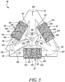
- Figures 5 and 6 schematically show a three-phase fault current limiter 40 configured to operate during a passive mode of operation and an active mode of operation, respectively.
- the fault current limiter 40 comprises a magnetically permeable (e.g. iron) core 41 forming a closed loop comprising three arms that are connected to form substantially the shape of a triangle.
- the loop may be in the shape of a circle, for example.
- the fault current limiter 40 comprises three coils, a first coil 45, a second coil 46 and a third coil 47. Each coil is wound about a respective arm of the looped core 41. Although not shown for ease of illustration, each coil 45, 46, 47 is connected in series with a respective distribution line of the power distribution network, corresponding to a single phase of the three phase system. That is, each coil 45, 46, 47 is configured to receive an alternating current that is one hundred and twenty degrees out of phase with each other coil 45, 46, 47 of the fault current limiter 40. That is, when the current through one of the coils, e.g. the first coil 45, is at a positive maximum amplitude, the current in each of the other two coils, e.g. the second and third coils 46, 47, is at negative half amplitude such that the net amplitude of the currents for all three phases is substantially zero.
- the core 41 of the fault current limiter 40 comprises a set of three magnetically permeable limbs: a first limb 411 extending from a first position 416 on the core 41 between the first coil 45 and the second coil 46, a second limb 412 extending from a second position 417 on the core 41 between the second coil 46 and the third coil 47, and a third limb 413 extending from a third position 418 on the core 41 between the third coil 47 and the first coil 45.
- Each one of the first, second and third positions 416, 417, 418 are substantially equidistant to their two adjacent coils 45, 46, 47.
- the first, second and third limbs 411, 412, 413 extend toward a centre of the loop, at which point there is located a magnetically permeable bridge element 42.
- the magnetically permeable bridge element 42 is rotatable (by a rotary actuator) about an axis 417 between a fully-open position 43 at which a magnetically insulating gap 44 is formed between a respective limb 411, 412, 413 and the bridge element 42 (as shown in Figure 5 ), and a fully-closed position 50 at which a connection is made between each limb 411, 412, 413 and the bridge element 42 (as shown in Figure 6 ), to provide magnetically permeable paths between the first position 416, the second position 417 and the third position 418 on the core 41 via the bridge element 42.
- any suitable rotary actuator mechanism may be used to make and correspondingly break the magnetically permeable path along the bridge element 42.
- the rotary actuator may comprise a motor or a torsional spring arrangement.
- the mechanism may also comprise one or more holding and damping arrangements to avoid overshoots and excessive impulse force, a locking/release mechanism and/or fail safe mechanisms, as appropriate.
- the bridge element may be linearly actuated.
- the (linear or rotary) actuation mechanism can be driven by an electrical source, electro mechanical source or any other source as appropriate.
- the movable bridge element 42 shown in Figures 5 and 6 is shaped to define three tabs each extending in a straight line from the axis 417 at substantially one hundred and twenty degrees relative to each other.
- the tabs and limbs 411, 412, 413 are of corresponding lengths such that, when the bridge element 42 is in the closed position 50, they are substantially flush with one another to define a magnetically permeable path between the first position 416, the second position 417 and the third position 418.
- the tabs and limbs 411, 412, 413 correspond in that they are shaped so that a tab of the moveable bridge element 42 conforms to the shape of a corresponding limb 411, 412, 413, and vice versa.
- the three coils 45, 46, 47 are wound about the core 41 such that a magnetic field 48 produced by an alternating current in the first coil 45 is substantially negated or cancelled by magnetic fields 49, 410 produced by currents in the second coil 46 and the third coil 47.
- Figures 5 and 6 illustrate this effect for a given snapshot in time for a three-phase alternating current.
- Figures 5 and 6 show the device 40 operating at a time when a current through the first coil 45 is at its greatest magnitude in a first direction, but a current through the second coil 46 and a current through the third coil 47 are each at half the maximum magnitude of the current in the first coil 45 and flow in a second, opposite direction to the first direction.
- the directions of the current through the coils 45, 46, 47 are illustrated in Figure 5 by crosses 414 and dots 415, where the crosses 414 represent current travelling into the page and the dots 415 represent current travelling out of the page.
- crosses 414 represent current travelling into the page
- dots 415 represent current travelling out of the page.
- the current in the first coil 45 flows in a clockwise direction whereas the currents in the second coil 46 and the third coil 47 flow in a counter-clockwise direction.
- the current in the first coil 45 flows in a counter-clockwise direction whereas the currents in the second coil 46 and the third coil 47 flow in a clockwise direction.
- the field 48 produced by the current in the first coil 45 is at its greatest magnitude in a first direction when the fields 49, 410 produced by the currents in the second and third coils 46, 47 will be at half magnitude in the opposite direction. In this way, the field 48 generated by the first coil in the first direction is negated by the fields 49, 410 generated by the second and third coils in the second direction.
- the fault current limiter 40 can be set to operate in either a passive mode of operation during which substantially zero net magnetic flux (and thus impedance) is sustained in core 41 and an active mode of operation during which a net magnetic flux is sustained in the core 41 such that there is an impedance to current across the coils 45, 46, 47.
- the fault current limiter comprises a controller 9 configured to cause the fault current limiter to switch between the passive mode of operation and the active mode of operation by moving the magnetically permeable bridge element between the fully-open position and the fully-closed position.
- the controller is configured to cause the fault current limiter to operate in the active mode of operation by moving the bridge element to the fully-closed position in response to detecting that a fault exists in the power distribution system.
- the controller 9 may be provided as part of the fault current limiter or as a separate entity configured to send appropriate control signalling to the movable bridge element.
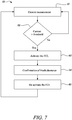
- Figure 7 is a flow diagram schematically illustrating operation of a controller 9 used in conjunction with a fault current limiter described above with respect to Figures 1 to 6 .
- the method begins at step 61 with the controller operating in the passive mode of operation where the bridge element is held in the fully-open position, such that substantially zero net magnetic flux is sustained across the core. In this way, an alternating current passing through the coils will experience little impedance and will therefore not be greatly influenced by the fault current limiter.
- the controller receives a current measurement indicating the magnitude of a current in the power distribution system.
- the controller detects whether a fault exists in the power distribution system based on the received current measurement. This may comprise the controller determining, based on the current measurement, whether the current in the power distribution system exceeds a pre-determined threshold value.
- step 62 If it is determined at step 62 that the current in the power distribution system does not exceed the pre-determined threshold current value, the controller will return to step 61 and receive an updated current measurements, before repeating step 62 with the updated measurement.
- step 62 If, however, it is determined at step 62 that the current in the power distribution system exceeds the pre-determined threshold current value, this can be taken as an indication that the electrical power system is experiencing a fault condition and the controller will accordingly activate the fault current limiter by switching to the active mode of operation.
- the controller will issue control signaling to cause the bridge element to be moved to (and held at) the fully-closed position, such that a net magnetic field is sustained across the core.
- alternating current passing through the coils will experience a relatively large impedance compared to the passive mode and will therefore be reduced by the fault current limiter.
- the fault current limiter will continue to operate in the active mode of operation until the fault is cleared. After the fault has been cleared the controller will receive confirmation of this at step 64. This may be in the form of a signal or input from a user of the electrical power system, or may be the result of a determination that the current has returned to a level that is below the threshold value, for example.
- the controller will de-activate the fault current limiter at step 65 by issuing a signal that will cause the bridge element to be returned to the fully-open position.
- the technology described herein is applicable more generally to any type of device for controlling a current in a power distribution system.
- the controller may be configured to operate in an intermediate mode of operation, e.g. during normal current levels, by moving the bridge element to an intermediate position between the fully-open position and the fully-closed position.
- the technology described herein may be used as a variable inductor, common mode filter or differential mode filter, as will now be described.
- the (fault current limiting) device can be used as a variable inductor by varying the position of the bridge element between the fully-open position and the fully-closed position to introduce different common mode and differential mode inductance.
- the device can be used in this way to control the current flow in the power line, both in fault conditions as well as normal current operating conditions.
- the (fault current limiting) device can also be used as a variable differential mode inductor by varying the position of the bridge element between the fully-open position and the fully-closed position to introduce different differential mode inductance.
- the (fault current limiting) device can be used as a variable frequency inductor by varying the speed at which the bridge element is rotated, to vary the inductance across the device.
- the location of the magnetically permeable bridge element at the fully-closed position, as well as the number of turns in the plurality of coils, will be set based on the level of inductance required during the fault condition and, e.g. considering the common mode inductance requirements that are needed during the normal operating conditions.
- the core has been described with respect to the drawings as forming a closed, i.e. continuous, loop, this is not required.
- the loop could instead form an open, i.e. discontinuous or broken, loop. This may be achieved by providing one or more magnetically-permeable gaps in the core.
Landscapes
- Engineering & Computer Science (AREA)
- Power Engineering (AREA)
- Emergency Protection Circuit Devices (AREA)
Claims (12)
- Vorrichtung (8) zum Steuern eines Stroms in einem N-Phasen-Stromverteilungssystem (2), wobei die Vorrichtung (8) Folgendes umfasst:einen magnetisch durchlässigen Kern (21, 41), der eine Schleife bildet;eine Vielzahl von Spulen (26, 27, 45, 46, 47), die um den Kern (21, 41) gewickelt ist, wobei jede Spule geeignet ist, um einen Wechselstrom von dem Stromverteilungssystem (2) zu empfangen, um ein zeitvariierendes Magnetfeld in dem Kern (21, 41) zu erzeugen;ein magnetisch durchlässiges Brückenelement (22, 42), das zwischen einer vollständig geschlossenen Position (24, 50), an der ein magnetisch durchlässiger Weg entlang des Brückenelements (22, 42) zwischen einer ersten Position an dem Kern (21, 41) und einer zweiten Position an dem Kern (21, 41) bereitgestellt ist, und einer vollständig offenen Position (23, 43) beweglich ist, an der ein magnetisch isolierender Spalt (25, 44) zwischen der ersten Position und der zweiten Position an dem Kern (21, 41) gebildet ist;wobei die Vielzahl von Spulen eine erste Spule und eine zweite Spule beinhaltet, wobei sich die erste Position an dem Kern (21, 41) zwischen der ersten und der zweiten Spule auf einer ersten Seite der ersten Spule befindet und sich die zweite Position an dem Kern (21, 41) zwischen der ersten und der zweiten Spule auf einer zweiten Seite der ersten Spule gegenüber der ersten Seite befindet;wobei die Vielzahl von Spulen (26, 27, 45, 46, 47) um den Kern (21, 41) gewickelt ist, sodass der Wechselstrom in der Vielzahl von Spulen (26, 27, 45, 46, 47) zeitvariierende Magnetfelder in Richtungen erzeugt, die Folgendes bereitstellen:einen Nettomagnetfluss von im Wesentlichen Null in dem Kern (21, 41), wenn sich das Brückenelement (22, 42) in der vollständig offenen Position (23, 43) befindet; undeinen Nettomagnetfluss ungleich Null in dem Kern (21, 41), wenn sich das Brückenelement (22, 42) in der vollständig geschlossenen Position (24, 50) befindet;dadurch gekennzeichnet, dass das Brückenelement (22, 42) konfiguriert ist, um durch einen mechanischen Aktuator (10) zwischen der offenen Position und der geschlossenen Position bewegbar zu sein, und die Vorrichtung (8) ferner eine Steuerung (9) umfasst, die konfiguriert ist, um das magnetisch durchlässige Brückenelement (22, 42) zwischen der vollständig offenen Position (23, 43) und der vollständig geschlossenen Position (24, 50) zu bewegen, um eine Menge an Nettomagnetfluss in dem Kern (21, 41) und dadurch eine Impedanz zu Strom durch die Spulen (26, 27, 45, 46, 47) zu steuern, wobei die Steuerung (9) konfiguriert ist, um den mechanischen Aktuator (10) zu steuern, um dadurch zu bewirken, dass die Vorrichtung (8) einen Strom in dem Stromverteilungssystem (2) begrenzt, indem das Brückenelement (22, 42) als Reaktion auf das Erfassen, dass ein Fehler in dem Stromverteilungssystem (2) vorliegt, in die vollständig geschlossene Position (24, 50) bewegt wird.
- Vorrichtung (8) nach Anspruch 1, wobei das Stromverteilungsnetz ein Gleichstromverteilungsnetz ist und die Vorrichtung (8) ferner einen Gleichstrom-Wechselstrom-Wandler umfasst, um einen Gleichstrom von dem Stromverteilungsnetz in einen Wechselstrom zu ändern, der durch die Vielzahl von Spulen (26, 27, 45, 46, 47) zu empfangen ist.
- Vorrichtung (8) nach Anspruch 1 oder 2, wobei:das Stromverteilungsnetz ein einphasiges Stromverteilungsnetz ist;die Vielzahl von Spulen (26, 27, 45, 46, 47) eine erste Spule und eine zweite Spule umfasst, die in Reihe verbunden sind; unddie Vielzahl von Spulen (26, 27, 45, 46, 47) gewickelt ist, sodass ein Wechselstrom in der ersten Spule ein Magnetfeld in einer ersten Richtung um die Schleife erzeugt und der gleiche Wechselstrom in der zweiten Spule ein Magnetfeld in einer zweiten, entgegengesetzten Richtung zu der ersten Richtung um die Schleife erzeugt.
- Vorrichtung (8) nach Anspruch 3, wobei die Vielzahl von Spulen (26, 27, 45, 46, 47) gewickelt ist, sodass eine Stromrichtung in der ersten Spule in einer entgegengesetzten Richtung zu derjenigen von Strom in der zweiten Spule relativ zu einer Umfangsrichtung um die Schleife ist.
- Vorrichtung (8) nach Anspruch 1 oder 2, wobei:das Stromverteilungsnetz ein mehrphasiges Stromverteilungsnetz ist;die Vielzahl von Spulen (26, 27, 45, 46, 47) eine Spule für jeden Phasenstrom des Stromverteilungssystems (2) umfasst; undjede Spule konfiguriert ist, um einen Wechselstrom von dem mehrphasigen Stromverteilungsnetz zu empfangen, der um 360/N Grad phasenverschoben zu jeder anderen Spule der Vorrichtung (8) ist.
- Vorrichtung (8) nach einem vorhergehenden Anspruch, wobei der mechanische Aktuator (10) ein linearer Aktuator (10) ist.
- Vorrichtung (8) nach einem der Ansprüche 1 bis 5, wobei der mechanische Aktuator (10) ein Drehaktuator (10) ist.
- Vorrichtung (8) nach einem der vorhergehenden Ansprüche, wobei die Steuerung (9) konfiguriert ist, um zu erfassen, dass ein Fehler in dem Stromverteilungssystem (2) vorliegt, wenn ein erfasster Strom in dem Stromverteilungssystem (2) einen vorbestimmten Schwellenstromwert überschreitet.
- Vorrichtung (8) nach einem vorhergehenden Anspruch, wobei die Steuerung (9) konfiguriert ist, um als variabler Induktor, Gleichtaktfilter oder Gegentaktfilter zu arbeiten, indem das Brückenelement (22, 42) in eine Zwischenposition zwischen der vollständig offenen Position (23, 43) und der vollständig geschlossenen Position (24, 50) bewegt wird.
- N-Phasen-Wechselstromverteilungssystem (2) mit N Verteilungsleitungen, eine Verteilungsleitung für jede Phase des Stromverteilungssystems (2), wobei jede Verteilungsleitung mit einer Vorrichtung (8) nach einem der Ansprüche 1 bis 9 verbunden ist.
- Verfahren zum Steuern des Betriebs einer Vorrichtung (8) nach einem der Ansprüche 1 bis 9, wobei in Verwendung das Verfahren umfasst, dass die Steuerung (9):die Vorrichtung (8) in einem passiven Betriebsmodus betreibt, in dem das Brückenelement (22, 42) in der vollständig offenen Position (23, 43) gehalten wird, sodass in dem Kern (21,41) ein Nettomagnetfluss von im Wesentlichen Null vorhanden ist;eine Strommessung empfängt, welche die Größe eines Stroms in dem Stromverteilungssystem (2) angibt;bestimmt, ob ein Fehler in dem Stromverteilungssystem (2) vorliegt, basierend auf der empfangenen Strommessung; undwenn bestimmt wird, dass ein Fehler in dem Stromverteilungssystem (2) vorliegt:
Umschalten der Vorrichtung (8), um in einem aktiven Betriebsmodus zu arbeiten, indem bewirkt wird, dass das Brückenelement (22, 42) in die vollständig geschlossene Position (24, 50) bewegt wird, sodass ein Nettomagnetfeld durch den Kern (21, 41) aufrechterhalten wird. - Verfahren nach Anspruch 11, wobei:das Bestimmen, ob ein Fehler in dem Stromverteilungssystem (2) vorliegt, basierend auf der empfangenen Strommessung, das Bestimmen basierend auf der empfangenen Strommessung umfasst, ob die Größe des Stroms in dem Stromverteilungssystem (2) einen vorbestimmten Schwellenwert überschreitet; undbestimmt wird, dass ein Fehler in dem Stromverteilungssystem (2) vorliegt, wenn die Größe des Stroms in dem Stromverteilungssystem (2) den vorbestimmten Schwellenstromwert überschreitet.
Applications Claiming Priority (1)
| Application Number | Priority Date | Filing Date | Title |
|---|---|---|---|
| GBGB1811128.6A GB201811128D0 (en) | 2018-07-06 | 2018-07-06 | Current controlling device |
Publications (2)
| Publication Number | Publication Date |
|---|---|
| EP3591674A1 EP3591674A1 (de) | 2020-01-08 |
| EP3591674B1 true EP3591674B1 (de) | 2021-05-05 |
Family
ID=63170822
Family Applications (1)
| Application Number | Title | Priority Date | Filing Date |
|---|---|---|---|
| EP19181959.8A Active EP3591674B1 (de) | 2018-07-06 | 2019-06-24 | Stromregelvorrichtung |
Country Status (4)
| Country | Link |
|---|---|
| US (1) | US10971927B2 (de) |
| EP (1) | EP3591674B1 (de) |
| CN (1) | CN110690690B (de) |
| GB (1) | GB201811128D0 (de) |
Families Citing this family (2)
| Publication number | Priority date | Publication date | Assignee | Title |
|---|---|---|---|---|
| DE102017109499A1 (de) * | 2017-05-03 | 2018-11-08 | Valeo Siemens Eautomotive Germany Gmbh | Inverter |
| US20240356453A1 (en) * | 2021-08-25 | 2024-10-24 | Enatel | Zero current sensor for a power converter |
Family Cites Families (10)
| Publication number | Priority date | Publication date | Assignee | Title |
|---|---|---|---|---|
| GB642326A (en) * | 1946-08-17 | 1950-08-30 | Nat Cylinder Gas Co | Magnetic control system |
| DE860233C (de) * | 1949-08-16 | 1952-12-18 | Frako Kondensator Apparate | Transformator mit regelbarer Sekundaerspannung |
| US4112404A (en) * | 1976-10-12 | 1978-09-05 | Boushey Homer A | Variable flux transformer |
| GB9027803D0 (en) * | 1990-12-21 | 1991-02-13 | Ici Plc | Electromagnetic device |
| US5930095A (en) * | 1996-08-16 | 1999-07-27 | Back Joo | Superconducting current limiting device by introducing the air gap in the magnetic core |
| GB2415833A (en) * | 2004-06-30 | 2006-01-04 | Areva T & D Uk Ltd | Inductive device with parallel permanent magnets in a magnetic circuit |
| FI20080085L (fi) * | 2008-02-06 | 2009-08-07 | Abb Technology Ag | Rinnakkaiskuristin |
| WO2011024179A2 (en) * | 2009-08-31 | 2011-03-03 | Bar Ilan Research & Development Company Ltd. | Improved fault current limiter with saturated core |
| FR2972866B1 (fr) * | 2011-03-18 | 2013-04-12 | Electricite De France | Limiteur serie de courant par circuit magnetique a trous et fenetres |
| US8830647B2 (en) | 2012-05-24 | 2014-09-09 | Mersen Usa Newburyport-Ma, Llc | Fault current limiter |
-
2018
- 2018-07-06 GB GBGB1811128.6A patent/GB201811128D0/en not_active Ceased
-
2019
- 2019-06-24 EP EP19181959.8A patent/EP3591674B1/de active Active
- 2019-06-25 US US16/451,455 patent/US10971927B2/en active Active
- 2019-07-05 CN CN201910603563.2A patent/CN110690690B/zh active Active
Also Published As
| Publication number | Publication date |
|---|---|
| US10971927B2 (en) | 2021-04-06 |
| EP3591674A1 (de) | 2020-01-08 |
| CN110690690B (zh) | 2023-08-25 |
| CN110690690A (zh) | 2020-01-14 |
| US20200014199A1 (en) | 2020-01-09 |
| GB201811128D0 (en) | 2018-08-22 |
Similar Documents
| Publication | Publication Date | Title |
|---|---|---|
| AU2010288086B2 (en) | Improved fault current limiter with saturated core | |
| CA3137550C (en) | Fault tolerant rotating electric machine | |
| US10971927B2 (en) | Current controlling device | |
| US20170170648A1 (en) | Protective device for protecting a transformer against geomagnetically induced currents | |
| CN104332977B (zh) | 磁通约束型三相故障电流限制器 | |
| RU2638299C2 (ru) | Устройство защиты обмоток однофазного трансформатора от повреждений | |
| Aktaibi et al. | Digital differential protection of power transformer using matlab | |
| Das et al. | 13.8-kV selective high-resistance grounding system for a geothermal generating plant—A case study | |
| US2432328A (en) | Current responsive time delay relay | |
| RU2704127C1 (ru) | Устройство защиты обмоток однофазного трансформатора от электрических повреждений | |
| CN203164335U (zh) | 一种tpy电流互感器暂态特性试验电路 | |
| WO2012103587A1 (en) | Fault current limiter with shield and adjacent cores | |
| CN102868142B (zh) | 一种用于短路冲击发电机运行的拓扑结构 | |
| CN107093908B (zh) | 兼具故障电流限制功能的三相不平衡治理器 | |
| RU2713880C1 (ru) | Устройство для защиты от обрывов вторичных цепей трансформаторов тока | |
| Hamza et al. | Different techniques for mitigation and reduction of power transformer inrush current | |
| CN113964991B (zh) | 一种环绕式副绕组及容错运行的电动机定子结构 | |
| Bryant et al. | Abnormal currents in distribution transformers due to lightning | |
| SU576639A1 (ru) | Способ и устройство дифференциальной токовой защиты трехфазной электроустановки | |
| Iwahara et al. | the Burden Critical Equipment | |
| US2486343A (en) | Circuit control apparatus | |
| Bronzeado et al. | The influence of tap position on the magnitude of transformer inrush current | |
| Pavlova | Operating conditions for current transformers in transition modes and their influence on relay protection | |
| US1594117A (en) | Electrical protective device | |
| Filipović-Grčić et al. | Current Transformer modeling in EMTP-RV for transients studies |
Legal Events
| Date | Code | Title | Description |
|---|---|---|---|
| PUAI | Public reference made under article 153(3) epc to a published international application that has entered the european phase |
Free format text: ORIGINAL CODE: 0009012 |
|
| STAA | Information on the status of an ep patent application or granted ep patent |
Free format text: STATUS: THE APPLICATION HAS BEEN PUBLISHED |
|
| AK | Designated contracting states |
Kind code of ref document: A1 Designated state(s): AL AT BE BG CH CY CZ DE DK EE ES FI FR GB GR HR HU IE IS IT LI LT LU LV MC MK MT NL NO PL PT RO RS SE SI SK SM TR |
|
| AX | Request for extension of the european patent |
Extension state: BA ME |
|
| RAP1 | Party data changed (applicant data changed or rights of an application transferred) |
Owner name: ROLLS-ROYCE PLC |
|
| STAA | Information on the status of an ep patent application or granted ep patent |
Free format text: STATUS: REQUEST FOR EXAMINATION WAS MADE |
|
| 17P | Request for examination filed |
Effective date: 20200701 |
|
| RBV | Designated contracting states (corrected) |
Designated state(s): AL AT BE BG CH CY CZ DE DK EE ES FI FR GB GR HR HU IE IS IT LI LT LU LV MC MK MT NL NO PL PT RO RS SE SI SK SM TR |
|
| GRAP | Despatch of communication of intention to grant a patent |
Free format text: ORIGINAL CODE: EPIDOSNIGR1 |
|
| STAA | Information on the status of an ep patent application or granted ep patent |
Free format text: STATUS: GRANT OF PATENT IS INTENDED |
|
| GRAJ | Information related to disapproval of communication of intention to grant by the applicant or resumption of examination proceedings by the epo deleted |
Free format text: ORIGINAL CODE: EPIDOSDIGR1 |
|
| STAA | Information on the status of an ep patent application or granted ep patent |
Free format text: STATUS: REQUEST FOR EXAMINATION WAS MADE |
|
| INTG | Intention to grant announced |
Effective date: 20201208 |
|
| INTC | Intention to grant announced (deleted) | ||
| GRAP | Despatch of communication of intention to grant a patent |
Free format text: ORIGINAL CODE: EPIDOSNIGR1 |
|
| STAA | Information on the status of an ep patent application or granted ep patent |
Free format text: STATUS: GRANT OF PATENT IS INTENDED |
|
| INTG | Intention to grant announced |
Effective date: 20210215 |
|
| GRAS | Grant fee paid |
Free format text: ORIGINAL CODE: EPIDOSNIGR3 |
|
| GRAA | (expected) grant |
Free format text: ORIGINAL CODE: 0009210 |
|
| STAA | Information on the status of an ep patent application or granted ep patent |
Free format text: STATUS: THE PATENT HAS BEEN GRANTED |
|
| AK | Designated contracting states |
Kind code of ref document: B1 Designated state(s): AL AT BE BG CH CY CZ DE DK EE ES FI FR GB GR HR HU IE IS IT LI LT LU LV MC MK MT NL NO PL PT RO RS SE SI SK SM TR |
|
| REG | Reference to a national code |
Ref country code: GB Ref legal event code: FG4D |
|
| REG | Reference to a national code |
Ref country code: CH Ref legal event code: EP |
|
| REG | Reference to a national code |
Ref country code: AT Ref legal event code: REF Ref document number: 1390849 Country of ref document: AT Kind code of ref document: T Effective date: 20210515 |
|
| REG | Reference to a national code |
Ref country code: DE Ref legal event code: R096 Ref document number: 602019004407 Country of ref document: DE |
|
| REG | Reference to a national code |
Ref country code: IE Ref legal event code: FG4D |
|
| REG | Reference to a national code |
Ref country code: LT Ref legal event code: MG9D |
|
| REG | Reference to a national code |
Ref country code: AT Ref legal event code: MK05 Ref document number: 1390849 Country of ref document: AT Kind code of ref document: T Effective date: 20210505 |
|
| PG25 | Lapsed in a contracting state [announced via postgrant information from national office to epo] |
Ref country code: FI Free format text: LAPSE BECAUSE OF FAILURE TO SUBMIT A TRANSLATION OF THE DESCRIPTION OR TO PAY THE FEE WITHIN THE PRESCRIBED TIME-LIMIT Effective date: 20210505 Ref country code: HR Free format text: LAPSE BECAUSE OF FAILURE TO SUBMIT A TRANSLATION OF THE DESCRIPTION OR TO PAY THE FEE WITHIN THE PRESCRIBED TIME-LIMIT Effective date: 20210505 Ref country code: LT Free format text: LAPSE BECAUSE OF FAILURE TO SUBMIT A TRANSLATION OF THE DESCRIPTION OR TO PAY THE FEE WITHIN THE PRESCRIBED TIME-LIMIT Effective date: 20210505 Ref country code: BG Free format text: LAPSE BECAUSE OF FAILURE TO SUBMIT A TRANSLATION OF THE DESCRIPTION OR TO PAY THE FEE WITHIN THE PRESCRIBED TIME-LIMIT Effective date: 20210805 Ref country code: AT Free format text: LAPSE BECAUSE OF FAILURE TO SUBMIT A TRANSLATION OF THE DESCRIPTION OR TO PAY THE FEE WITHIN THE PRESCRIBED TIME-LIMIT Effective date: 20210505 |
|
| PG25 | Lapsed in a contracting state [announced via postgrant information from national office to epo] |
Ref country code: SE Free format text: LAPSE BECAUSE OF FAILURE TO SUBMIT A TRANSLATION OF THE DESCRIPTION OR TO PAY THE FEE WITHIN THE PRESCRIBED TIME-LIMIT Effective date: 20210505 Ref country code: PT Free format text: LAPSE BECAUSE OF FAILURE TO SUBMIT A TRANSLATION OF THE DESCRIPTION OR TO PAY THE FEE WITHIN THE PRESCRIBED TIME-LIMIT Effective date: 20210906 Ref country code: RS Free format text: LAPSE BECAUSE OF FAILURE TO SUBMIT A TRANSLATION OF THE DESCRIPTION OR TO PAY THE FEE WITHIN THE PRESCRIBED TIME-LIMIT Effective date: 20210505 Ref country code: PL Free format text: LAPSE BECAUSE OF FAILURE TO SUBMIT A TRANSLATION OF THE DESCRIPTION OR TO PAY THE FEE WITHIN THE PRESCRIBED TIME-LIMIT Effective date: 20210505 Ref country code: NO Free format text: LAPSE BECAUSE OF FAILURE TO SUBMIT A TRANSLATION OF THE DESCRIPTION OR TO PAY THE FEE WITHIN THE PRESCRIBED TIME-LIMIT Effective date: 20210805 Ref country code: LV Free format text: LAPSE BECAUSE OF FAILURE TO SUBMIT A TRANSLATION OF THE DESCRIPTION OR TO PAY THE FEE WITHIN THE PRESCRIBED TIME-LIMIT Effective date: 20210505 Ref country code: IS Free format text: LAPSE BECAUSE OF FAILURE TO SUBMIT A TRANSLATION OF THE DESCRIPTION OR TO PAY THE FEE WITHIN THE PRESCRIBED TIME-LIMIT Effective date: 20210905 Ref country code: GR Free format text: LAPSE BECAUSE OF FAILURE TO SUBMIT A TRANSLATION OF THE DESCRIPTION OR TO PAY THE FEE WITHIN THE PRESCRIBED TIME-LIMIT Effective date: 20210806 |
|
| REG | Reference to a national code |
Ref country code: NL Ref legal event code: MP Effective date: 20210505 |
|
| PG25 | Lapsed in a contracting state [announced via postgrant information from national office to epo] |
Ref country code: NL Free format text: LAPSE BECAUSE OF FAILURE TO SUBMIT A TRANSLATION OF THE DESCRIPTION OR TO PAY THE FEE WITHIN THE PRESCRIBED TIME-LIMIT Effective date: 20210505 |
|
| PG25 | Lapsed in a contracting state [announced via postgrant information from national office to epo] |
Ref country code: EE Free format text: LAPSE BECAUSE OF FAILURE TO SUBMIT A TRANSLATION OF THE DESCRIPTION OR TO PAY THE FEE WITHIN THE PRESCRIBED TIME-LIMIT Effective date: 20210505 Ref country code: ES Free format text: LAPSE BECAUSE OF FAILURE TO SUBMIT A TRANSLATION OF THE DESCRIPTION OR TO PAY THE FEE WITHIN THE PRESCRIBED TIME-LIMIT Effective date: 20210505 Ref country code: SK Free format text: LAPSE BECAUSE OF FAILURE TO SUBMIT A TRANSLATION OF THE DESCRIPTION OR TO PAY THE FEE WITHIN THE PRESCRIBED TIME-LIMIT Effective date: 20210505 Ref country code: CZ Free format text: LAPSE BECAUSE OF FAILURE TO SUBMIT A TRANSLATION OF THE DESCRIPTION OR TO PAY THE FEE WITHIN THE PRESCRIBED TIME-LIMIT Effective date: 20210505 Ref country code: DK Free format text: LAPSE BECAUSE OF FAILURE TO SUBMIT A TRANSLATION OF THE DESCRIPTION OR TO PAY THE FEE WITHIN THE PRESCRIBED TIME-LIMIT Effective date: 20210505 Ref country code: SM Free format text: LAPSE BECAUSE OF FAILURE TO SUBMIT A TRANSLATION OF THE DESCRIPTION OR TO PAY THE FEE WITHIN THE PRESCRIBED TIME-LIMIT Effective date: 20210505 Ref country code: RO Free format text: LAPSE BECAUSE OF FAILURE TO SUBMIT A TRANSLATION OF THE DESCRIPTION OR TO PAY THE FEE WITHIN THE PRESCRIBED TIME-LIMIT Effective date: 20210505 |
|
| REG | Reference to a national code |
Ref country code: DE Ref legal event code: R097 Ref document number: 602019004407 Country of ref document: DE |
|
| REG | Reference to a national code |
Ref country code: BE Ref legal event code: MM Effective date: 20210630 |
|
| PLBE | No opposition filed within time limit |
Free format text: ORIGINAL CODE: 0009261 |
|
| STAA | Information on the status of an ep patent application or granted ep patent |
Free format text: STATUS: NO OPPOSITION FILED WITHIN TIME LIMIT |
|
| PG25 | Lapsed in a contracting state [announced via postgrant information from national office to epo] |
Ref country code: MC Free format text: LAPSE BECAUSE OF FAILURE TO SUBMIT A TRANSLATION OF THE DESCRIPTION OR TO PAY THE FEE WITHIN THE PRESCRIBED TIME-LIMIT Effective date: 20210505 Ref country code: LU Free format text: LAPSE BECAUSE OF NON-PAYMENT OF DUE FEES Effective date: 20210624 |
|
| 26N | No opposition filed |
Effective date: 20220208 |
|
| PG25 | Lapsed in a contracting state [announced via postgrant information from national office to epo] |
Ref country code: IE Free format text: LAPSE BECAUSE OF NON-PAYMENT OF DUE FEES Effective date: 20210624 |
|
| PG25 | Lapsed in a contracting state [announced via postgrant information from national office to epo] |
Ref country code: IS Free format text: LAPSE BECAUSE OF FAILURE TO SUBMIT A TRANSLATION OF THE DESCRIPTION OR TO PAY THE FEE WITHIN THE PRESCRIBED TIME-LIMIT Effective date: 20210905 Ref country code: AL Free format text: LAPSE BECAUSE OF FAILURE TO SUBMIT A TRANSLATION OF THE DESCRIPTION OR TO PAY THE FEE WITHIN THE PRESCRIBED TIME-LIMIT Effective date: 20210505 |
|
| PG25 | Lapsed in a contracting state [announced via postgrant information from national office to epo] |
Ref country code: IT Free format text: LAPSE BECAUSE OF FAILURE TO SUBMIT A TRANSLATION OF THE DESCRIPTION OR TO PAY THE FEE WITHIN THE PRESCRIBED TIME-LIMIT Effective date: 20210505 Ref country code: BE Free format text: LAPSE BECAUSE OF NON-PAYMENT OF DUE FEES Effective date: 20210630 |
|
| REG | Reference to a national code |
Ref country code: CH Ref legal event code: PL |
|
| PG25 | Lapsed in a contracting state [announced via postgrant information from national office to epo] |
Ref country code: LI Free format text: LAPSE BECAUSE OF NON-PAYMENT OF DUE FEES Effective date: 20220630 Ref country code: CH Free format text: LAPSE BECAUSE OF NON-PAYMENT OF DUE FEES Effective date: 20220630 |
|
| PG25 | Lapsed in a contracting state [announced via postgrant information from national office to epo] |
Ref country code: CY Free format text: LAPSE BECAUSE OF FAILURE TO SUBMIT A TRANSLATION OF THE DESCRIPTION OR TO PAY THE FEE WITHIN THE PRESCRIBED TIME-LIMIT Effective date: 20210505 |
|
| P01 | Opt-out of the competence of the unified patent court (upc) registered |
Effective date: 20230528 |
|
| PG25 | Lapsed in a contracting state [announced via postgrant information from national office to epo] |
Ref country code: HU Free format text: LAPSE BECAUSE OF FAILURE TO SUBMIT A TRANSLATION OF THE DESCRIPTION OR TO PAY THE FEE WITHIN THE PRESCRIBED TIME-LIMIT; INVALID AB INITIO Effective date: 20190624 |
|
| PG25 | Lapsed in a contracting state [announced via postgrant information from national office to epo] |
Ref country code: MK Free format text: LAPSE BECAUSE OF FAILURE TO SUBMIT A TRANSLATION OF THE DESCRIPTION OR TO PAY THE FEE WITHIN THE PRESCRIBED TIME-LIMIT Effective date: 20210505 |
|
| PG25 | Lapsed in a contracting state [announced via postgrant information from national office to epo] |
Ref country code: MT Free format text: LAPSE BECAUSE OF FAILURE TO SUBMIT A TRANSLATION OF THE DESCRIPTION OR TO PAY THE FEE WITHIN THE PRESCRIBED TIME-LIMIT Effective date: 20210505 |
|
| PGFP | Annual fee paid to national office [announced via postgrant information from national office to epo] |
Ref country code: DE Payment date: 20250626 Year of fee payment: 7 |
|
| PGFP | Annual fee paid to national office [announced via postgrant information from national office to epo] |
Ref country code: GB Payment date: 20250617 Year of fee payment: 7 |
|
| PGFP | Annual fee paid to national office [announced via postgrant information from national office to epo] |
Ref country code: FR Payment date: 20250624 Year of fee payment: 7 |
|
| PG25 | Lapsed in a contracting state [announced via postgrant information from national office to epo] |
Ref country code: TR Free format text: LAPSE BECAUSE OF FAILURE TO SUBMIT A TRANSLATION OF THE DESCRIPTION OR TO PAY THE FEE WITHIN THE PRESCRIBED TIME-LIMIT Effective date: 20210505 |