EP3591613A1 - Mobile entity detector, mobile entity detection method, and computer-readable recording medium - Google Patents
Mobile entity detector, mobile entity detection method, and computer-readable recording medium Download PDFInfo
- Publication number
- EP3591613A1 EP3591613A1 EP18761193.4A EP18761193A EP3591613A1 EP 3591613 A1 EP3591613 A1 EP 3591613A1 EP 18761193 A EP18761193 A EP 18761193A EP 3591613 A1 EP3591613 A1 EP 3591613A1
- Authority
- EP
- European Patent Office
- Prior art keywords
- mobile entity
- optical flow
- cluster
- image data
- clusters
- Prior art date
- Legal status (The legal status is an assumption and is not a legal conclusion. Google has not performed a legal analysis and makes no representation as to the accuracy of the status listed.)
- Granted
Links
Images




Classifications
-
- G—PHYSICS
- G06—COMPUTING OR CALCULATING; COUNTING
- G06T—IMAGE DATA PROCESSING OR GENERATION, IN GENERAL
- G06T7/00—Image analysis
- G06T7/20—Analysis of motion
- G06T7/215—Motion-based segmentation
-
- G—PHYSICS
- G06—COMPUTING OR CALCULATING; COUNTING
- G06F—ELECTRIC DIGITAL DATA PROCESSING
- G06F18/00—Pattern recognition
- G06F18/20—Analysing
- G06F18/21—Design or setup of recognition systems or techniques; Extraction of features in feature space; Blind source separation
- G06F18/211—Selection of the most significant subset of features
- G06F18/2113—Selection of the most significant subset of features by ranking or filtering the set of features, e.g. using a measure of variance or of feature cross-correlation
-
- G—PHYSICS
- G06—COMPUTING OR CALCULATING; COUNTING
- G06F—ELECTRIC DIGITAL DATA PROCESSING
- G06F18/00—Pattern recognition
- G06F18/20—Analysing
- G06F18/23—Clustering techniques
- G06F18/231—Hierarchical techniques, i.e. dividing or merging pattern sets so as to obtain a dendrogram
-
- G—PHYSICS
- G06—COMPUTING OR CALCULATING; COUNTING
- G06T—IMAGE DATA PROCESSING OR GENERATION, IN GENERAL
- G06T7/00—Image analysis
- G06T7/20—Analysis of motion
- G06T7/246—Analysis of motion using feature-based methods, e.g. the tracking of corners or segments
-
- G—PHYSICS
- G06—COMPUTING OR CALCULATING; COUNTING
- G06V—IMAGE OR VIDEO RECOGNITION OR UNDERSTANDING
- G06V20/00—Scenes; Scene-specific elements
- G06V20/50—Context or environment of the image
- G06V20/56—Context or environment of the image exterior to a vehicle by using sensors mounted on the vehicle
- G06V20/58—Recognition of moving objects or obstacles, e.g. vehicles or pedestrians; Recognition of traffic objects, e.g. traffic signs, traffic lights or roads
- G06V20/584—Recognition of moving objects or obstacles, e.g. vehicles or pedestrians; Recognition of traffic objects, e.g. traffic signs, traffic lights or roads of vehicle lights or traffic lights
-
- G—PHYSICS
- G06—COMPUTING OR CALCULATING; COUNTING
- G06T—IMAGE DATA PROCESSING OR GENERATION, IN GENERAL
- G06T2207/00—Indexing scheme for image analysis or image enhancement
- G06T2207/10—Image acquisition modality
- G06T2207/10016—Video; Image sequence
-
- G—PHYSICS
- G06—COMPUTING OR CALCULATING; COUNTING
- G06T—IMAGE DATA PROCESSING OR GENERATION, IN GENERAL
- G06T2207/00—Indexing scheme for image analysis or image enhancement
- G06T2207/30—Subject of image; Context of image processing
- G06T2207/30241—Trajectory
-
- G—PHYSICS
- G06—COMPUTING OR CALCULATING; COUNTING
- G06T—IMAGE DATA PROCESSING OR GENERATION, IN GENERAL
- G06T2207/00—Indexing scheme for image analysis or image enhancement
- G06T2207/30—Subject of image; Context of image processing
- G06T2207/30248—Vehicle exterior or interior
- G06T2207/30252—Vehicle exterior; Vicinity of vehicle
-
- G—PHYSICS
- G06—COMPUTING OR CALCULATING; COUNTING
- G06V—IMAGE OR VIDEO RECOGNITION OR UNDERSTANDING
- G06V2201/00—Indexing scheme relating to image or video recognition or understanding
- G06V2201/08—Detecting or categorising vehicles
Definitions
- the present invention relates to a mobile entity detection apparatus and a mobile entity detection method for detecting a mobile entity from an image captured with an imaging device, and further relates to a computer-readable recording medium where a program for realizing these is recorded.
- Patent Documents 1 and 2 both disclose a mobile entity detection apparatus to be mounted in a vehicle.
- the mobile entity detection apparatus disclosed in Patent Documents 1 and 2 first extracts feature points from respective images successively output at a set interval from a camera, then compares the extracted feature points between images, and generates an optical flow that links the feature points.
- the mobile entity detection apparatus disclosed in Patent Document 1 selects an optical flow that satisfies setting conditions. There are two setting conditions at this time, with one condition being that an extension line of the optical flow intersects at one vanishing point with a predetermined error range. The other condition is that in the extension line of the optical flow, with one end point of the optical flow serving as an external division point, an external division ratio of a line that links the other end point of the optical flow with the vanishing point is equal within the predetermined error range. Also, the mobile entity detection apparatus disclosed in Patent Document 1 detects a mobile entity from a selected optical flow.
- a mobile entity at the periphery of a vehicle can be detected, so for example, if a configuration is adopted in which a mobile entity is detected based on an image from a rear camera that captures images rearward from the vehicle, the driver can recognize a vehicle positioned to the rear.
- the mobile entity detection apparatuses disclosed in above Patent Documents 1 and 2 the mobile entity is detected by selecting an optical flow that intersects at one vanishing point. Therefore, with the mobile entity detection apparatuses disclosed in above Patent Documents 1 and 2, since an object forming part of a background, for example, such as road markings, a parked vehicle, or a signboard, moves relative to the vehicle, it is possible that such an object will be falsely detected.
- An example object of the present invention is to provide a mobile entity detection apparatus, a mobile entity detection method, and a computer-readable recording medium that address the above-described problem, and are capable of improving the accuracy of mobile entity detection by distinguishing between a mobile entity and an object forming part of a background.
- a mobile entity detection apparatus is an apparatus for detecting a mobile entity from image data output by an imaging device installed in a vehicle, the detection apparatus including:
- a mobile entity detection method is a method for detecting a mobile entity from image data output by an imaging device installed in a vehicle, the method including:
- a computer-readable recording medium includes a program recorded thereon for, with a computer, detecting a mobile entity from image data output by an imaging device installed in a vehicle, the program including instructions that cause the computer to carry out:
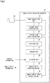
- FIG. 1 is a block diagram showing the schematic configuration of the mobile entity detection apparatus according to this example embodiment of the present invention.
- a mobile entity detection apparatus 10 in this example embodiment, shown in FIG. 1 is an apparatus for detecting a mobile entity from image data output by an imaging device installed in a vehicle.
- the mobile entity detection apparatus 10 includes a feature point extraction unit 11, an optical flow specification unit 12, a clustering unit 13, a filtering unit 14, and a mobile entity specification unit 15.
- the feature point extraction unit 11 extracts, from image data successively output at a set interval by the imaging device, a feature point moving in an image.
- the optical flow specification unit 12 compares the latest image data with image data that was output further in the past, and specify an optical flow for each feature point extracted.
- the clustering unit 13 performs clustering on all of the obtained optical flows based on the specified optical flows and the position of the specified optical flows in the image, and separate each optical flow into a cluster.
- the filtering unit 14 removes a cluster that corresponds to an object forming a background from among clusters obtained by clustering, based on the traveling direction and speed of the vehicle.
- the mobile entity specification unit 15 specifies a mobile entity in the image using a result of clustering after cluster removal by the filtering unit 14.
- the mobile entity detection apparatus 10 detects a mobile entity by clustering optical flows of feature points, and removing a cluster that corresponds to a background from the obtained clusters. Therefore, according to this example embodiment, it is possible to improve the accuracy of mobile entity detection by distinguishing between a mobile entity and an object forming a background.
- FIG. 2 is a block diagram showing the specific configuration of the mobile entity detection apparatus according to this example embodiment of the present invention.
- the mobile entity detection apparatus 10 in this example embodiment is connected to an external imaging device 20.
- the imaging device 20 includes a solid-state imaging sensor, and when performing imaging, outputs image data of a color image to the mobile entity detection apparatus 10.
- the imaging device 20 continuously outputs image data at a set time interval (frame rate).
- the mobile entity detection apparatus 10 includes an image acquisition unit 16, a tracking unit 17, and a mobile entity speed calculation unit 18, in addition to the feature point extraction unit 11, the optical flow specification unit 12, the clustering unit 13, the filtering unit 14, and the mobile entity specification unit 15.
- the image acquisition unit 16 acquires image data to be processed from the imaging device 20. Specifically, because image data of a color image is output from the imaging device 20, first, the image acquisition unit 16 performs image conversion on the image data that has been output to convert the color image into a grayscale image. Next, the image acquisition unit 16 executes distortion correction on the image data as necessary, and then inputs the corrected image data to the feature point extraction unit 11 and the optical flow specification unit 12. Note that distortion correction is performed, for example, when a shooting lens attached to the imaging device 20 is a fisheye lens or the like.
- the feature point extraction unit 11 first calculates an unbiased variance of luminance change using image data for a predetermined number of frames (for example, 10 frames), and compares the calculated value with a threshold value to determine whether each pixel corresponds to a moving pixel or a stationary pixel. Then, the feature point extraction unit 11 sets an area in which a pixel determined to be a moving pixel exists as a movement area in which a mobile entity exists. Next, the feature point extraction unit 11 extracts feature points in the movement area of the image data of the current frame using, for example, an ordinary FAST algorithm.
- the optical flow specification unit 12 first compares the feature points of a past frame that is one frame prior to the current frame with the feature points of the current frame, and links together feature points that correspond to each other.
- the optical flow specification unit 12 links a feature point 1 of the past frame that is one frame prior to the current frame with a feature point 3 of the current frame, and links a feature point 2 of the past frame that is one frame prior to the current frame with a feature point 4 of the current frame.
- the optical flow specification unit 12 connects the linked feature points together to specify an optical flow.
- FIG. 3 illustrates processing to specify an optical flow of feature points according to an example embodiment of the present invention.
- the optical flow specification unit 12 calculates the degree of similarity between feature points, and links feature points together whose calculated degree of similarity is at least a threshold value.
- the degree of similarity used in this case is, for example, a Hamming distance calculated from binary code generated by a Rotated Brief method.
- the optical flow specification unit 12 can also specify an optical flow in a case where, in order to shorten the processing time, the image is divided, each area obtained by the division and the area at the periphery of that area is set as one group, and feature points are connected together for each group.
- the optical flow specification unit 12 can acquire vehicle information from a vehicle (hereinafter referred to as the "host vehicle") where the mobile entity detection apparatus 10 is mounted, and can specify the traveling direction and the speed of the host vehicle.
- vehicle information is information that specifies the state (forward or reverse), the turning angle, the speed, and the like of the host vehicle.
- the optical flow specification unit 12 removes an optical flow related to an object forming a background from among the specified optical flows based on the traveling direction and speed of the host vehicle.
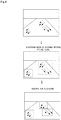
- the clustering unit 13 executes clustering using an x-mean algorithm. For example, as shown in FIG. 4 , the clustering unit 13 first specifies the distance between optical flows, and executes clustering based on the specified distance.
- FIG. 4 illustrates processing to perform optical flow clustering according to an example embodiment of the present invention.
- the clustering unit 13 specifies, for each cluster generated by the clustering, an optical flow whose length, position (coordinates in a screen), and direction deviate greatly from the average value of optical flows in that cluster.
- the specified optical flow is not considered to originate from the same mobile entity, so the clustering unit 13 removes the specified optical flow from the original cluster, and registers this optical flow in a newly generated cluster, as shown in FIG. 4 .
- the clustering unit 13 After executing clustering, in a case where, among a plurality of the clusters, the positional relationship between the plurality of clusters, and the length and direction of the respective optical flows of the clusters, satisfy set conditions, the clustering unit 13 combines these clusters as a single cluster. The reason for this is that the optical flows of these clusters can be considered to originate from the same mobile entity.
- the clustering unit 13 first specifies two clusters as combination candidates, based on a condition that the clusters overlap each other, and a condition that the average length and the direction of the optical flows in the clusters is similar between the clusters. Next, the clustering unit 13 compares the direction of the optical flows in a central area (for example, 20 pixels ⁇ 20 pixels) when connecting the centers of the two clusters specified as combination candidates to each other, and the clustering unit 13 combines these combination candidates when the direction is the same for each cluster.
- a central area for example, 20 pixels ⁇ 20 pixels
- the tracking unit 17 determines, for each cluster obtained by clustering, whether or not the position of each cluster overlaps a position predicted from image data other than the latest image data. Specifically, the tracking unit 17 compares a cluster that is the determination target in the current frame with a cluster that is the determination target in a plurality of past frames (for example, the past 6 frames), and if the positions of these clusters match in at least a fixed number of past frames, the tracking unit 17 determines that the position of the cluster in the current frame overlaps the predicted position. Then, the tracking unit 17 notifies the filtering unit 14 of the clusters determined to overlap.
- the tracking unit 17 determines that there is overlapping not only in a case where the cluster in the current frame completely matches the cluster in the past frames, but also in a case where both clusters overlap by at least a fixed ratio. Furthermore, in order to prevent clusters corresponding to different mobile entities from being matched to each other, the tracking unit 17 also can reduce the area of the cluster that is the determination target (for example, 1/4), and then perform the matching determination.
- the tracking unit 17 can also calculate, as coordinates of the cluster that is the determination target, average coordinates of the coordinates of the cluster in the current frame and the coordinates of the matched cluster of the past frames, and use the calculated average coordinates as the coordinates of the cluster that is the determination target.
- the tracking unit 17 deletes the cluster that is the determination target.
- the tracking unit 17 can also restore the deleted cluster.
- the filtering unit 14 first acquires vehicle information from the host vehicle, and specifies the traveling direction and the speed of the host vehicle.
- vehicle information is information that specifies the state (forward or reverse), the turning angle, the speed, and the like of the host vehicle.
- the filtering unit 14 specifies clusters that correspond to an object forming a background, and removes the specified clusters.
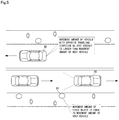
- FIG. 5 illustrates processing to perform background removal according to an example embodiment of the present invention. Note that in FIG. 5 , the broken lines to the rear of the host vehicle 30 indicate an imaging range of the imaging device.
- the filtering unit 14 first specifies optical flows whose movement direction is opposite to the movement direction of the host vehicle 30, and whose movement amount is at least as much as the movement amount of the host vehicle 30. Next, the filtering unit 14 specifies a cluster including a specified optical flow as a cluster that corresponds to an object forming a background, and removes the specified cluster.
- the mobile entity specification unit 15 specifies a mobile entity based on a cluster other than the clusters that were removed by the tracking unit 17 and the filtering unit 14. Also, the mobile entity specification unit 15 gives notification of information of the specified mobile entity to the vehicle. Examples of the information given in this notification include the position in an image, the movement direction, the speed, and the like of the mobile entity. Note that the speed is calculated by the mobile entity calculation unit 18, described later.
- the mobile entity speed calculation unit 18 using the direction and length of the optical flows regarding the mobile entity specified by the mobile entity specification unit 15, calculates the speed (relative speed) of the specified mobile entity with respect to the mobile entity detection apparatus 10 (the host vehicle).
- the mobile entity speed calculation unit 18 first specifies the coordinates at a point nearest to the host vehicle of the specified mobile entity (a point at the lower right or the lower left in the screen of the mobile entity), in the current frame and in a past frame that is one frame prior to the current frame, respectively. Note that the coordinates specified in the past frame that is one frame prior to the current frame are taken as start coordinates, and the coordinates specified in the current frame are taken as end coordinates. Also, the mobile entity speed calculation unit 18 can estimate the start coordinates from the average length and angle of the optical flows of the specified mobile entity. FIG. 6 illustrates processing to calculate the relative speed of the mobile entity according to an example embodiment of the present invention.
- the mobile entity speed calculation unit 18 performs bird's-eye-view conversion using camera parameters of the imaging device 20 to convert the start coordinates and the end coordinates to coordinates in a real coordinate system. Also, the mobile entity speed calculation unit 18, from the coordinates after conversion, calculates the distance between the start coordinates and the end coordinates in real space, and adopts the calculated distance as the relative movement distance.
- the mobile entity speed calculation unit 18 calculates the speed of the mobile entity with respect to the host vehicle.
- the time from the past frame that is one frame prior to the current frame until the current frame can be calculated from the frame rate. For example, if the frame rate is 10 fps, the time is 0.1 seconds.
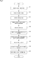
- FIG. 7 is a flowchart showing operation of the mobile entity detection apparatus according to this example embodiment of the present invention.
- the following description refers to FIGS. 1 to 6 as appropriate.
- a mobile entity detection method is implemented by operating the mobile entity detection apparatus 10.
- the description of the mobile entity detection method in this example embodiment can be replaced with the description of operation of the mobile entity detection apparatus 10 below.
- the image acquisition unit 16 acquires image data output from the imaging device 20 for each frame (step A1).
- step A1 the image acquisition unit 16 first performs conversion to a grayscale image, distortion correction, and the like on the acquired image data. Then, after the number of frames of acquired image data reaches a set number of frames, the image acquisition unit 16 transfers this image data to the feature point extraction unit 11.
- the feature point extraction unit 11 extracts feature points moving in an image from the image data acquired in step A1 (step A2).
- the feature point extraction unit 11 using image data of a number of frames (for example, 10 frames) set in advance, calculates the unbiased variance of luminance change, and determines whether each pixel corresponds to a moving pixel or a stationary pixel. Then, the feature point extraction unit 11 extracts feature points from a movement area where a pixel determined to be a moving pixel was determined to exist.
- a number of frames for example, 10 frames
- the optical flow specification unit 12 compares the latest image data with image data that was output further in the past, and specifies an optical flow for each feature point that was extracted (step A3).
- the optical flow specification unit 12 compares the feature points of a past frame that is one frame prior to the current frame with the feature points of the current frame, and links together feature points that correspond to each other, and connects together the feature points that were linked, thereby specifying an optical flow.
- the optical flow specification unit 12 removes an optical flow related to an object forming a background from the optical flows specified in step A3 based on the traveling direction and speed of the host vehicle (step A4).
- the clustering unit 13 performs clustering on all obtained optical flows based on the specified optical flows and the position of the specified optical flows in an image, and separates each optical flow into a cluster (step A5).
- the clustering unit 13 first specifies the distance between the optical flows, and executes clustering based on the specified distance. Next, the clustering unit 13 removes, from a cluster, an optical flow whose length, position (coordinates in a screen), and direction deviate greatly from the average value of the optical flows in that cluster, and registers this optical flow in a newly generated cluster.
- the tracking unit 17 determines, for each cluster obtained by clustering, whether the position of each cluster overlaps a position predicted from image data other than the latest image data, and removes clusters that do not overlap as unnecessary clusters (step A6).
- the filtering unit 14 specifies a cluster that corresponds to an object forming a background, and removes the specified cluster (step A7).
- the mobile entity specification unit 15 specifies a mobile entity based on a cluster other than the clusters that were removed in steps A6 and A7 (step A8).
- the mobile entity speed calculation unit 18 uses the direction and length of the optical flows regarding the mobile entity specified by step A3, calculates the relative speed of the specified mobile entity with respect to the mobile entity detection apparatus 10 (the host vehicle)(step A9).
- step A9 when the speed of the mobile entity is calculated in step A9, the mobile entity specification unit 15 generates mobile entity information including that speed, and notifies the vehicle of the generated mobile entity information (step A10). Also, when step A10 is executed, the vehicle displays the mobile entity information in an instrument panel or the like, and performs collision detection processing, for example.
- the mobile entity detection apparatus 10 detects a mobile entity by clustering optical flows of feature points, and removing a cluster that corresponds to a background from the obtained clusters. Therefore, according to this example embodiment, it is possible to improve the accuracy of mobile entity detection by distinguishing between a mobile entity and an object forming part of a background.
- tracking is performed by the tracking unit 17, so it is possible to respond to a situation where instantaneous false detection occurs. Furthermore, a cluster that was deleted by the tracking can be restored by the tracking unit 17 based on past frames, so it is also possible to respond to a situation where the mobile entity detection is interrupted for some reason.
- a program according to this example embodiment may be a program that causes a computer to execute steps A1 to A10 shown in FIG 7 .
- the mobile entity detection apparatus 10 and the mobile entity detection method according to this example embodiment can be realized.
- a processor of the computer performs processing to function as the feature point extraction unit 11, the optical flow specification unit 12, the clustering unit 13, the filtering unit 14, the mobile entity specification unit 15, the image acquisition unit 16, the tracking unit 17, and the mobile entity speed calculation unit 18.
- examples of the computer include a computer installed in a vehicle, a general-purpose computer, a computer installed in a portable information terminal, and the like.
- each computer may respectively function as any of the feature point extraction unit 11, the optical flow specification unit 12, the clustering unit 13, the filtering unit 14, the mobile entity specification unit 15, the image acquisition unit 16, the tracking unit 17, and the mobile entity speed calculation unit 18.
- FIG. 8 is a block diagram showing an example of a computer that realizes the mobile entity detection apparatus according to an example embodiment of the present invention.
- the computer 110 includes a CPU (Central Processing Unit) 111, a main memory 112, a storage device 113, an input interface 114, a display controller 115, a data reader/writer 116, and a communications interface 117. These units are each connected so as to be capable of performing data communications with each other through a bus 121.
- the computer 110 may also include a GPU (Graphics Processing Unit) or an FPGA (Field-Programmable Gate Array) in addition to the CPU 111 or instead of the CPU 111.
- GPU Graphics Processing Unit
- FPGA Field-Programmable Gate Array
- the CPU 111 opens the program (code) according to this example embodiment, which has been stored in the storage device 113, in the main memory 112 and performs various operations by executing the program in a predetermined order.
- the main memory 112 is typically a volatile storage device such as a DRAM (Dynamic Random Access Memory).
- the program according to this example embodiment is provided in a state stored in a computer-readable recording medium 120. Note that the program according to this example embodiment may be distributed on the Internet, which is connected through the communications interface 117.
- the input interface 114 mediates data transmission between the CPU 111 and an input device 118, which may be a keyboard or mouse.
- the display controller 115 is connected to a display device 119, and controls display by the display device 119.
- the data reader/writer 116 mediates data transmission between the CPU 111 and the recording medium 120, and executes reading of a program from the recording medium 120 and writing of processing results in the computer 110 to the recording medium 120.
- the communications interface 117 mediates data transmission between the CPU 111 and other computers.
- CF Compact Flash (registered trademark)
- SD Secure Digital
- a magnetic recording medium such as a Flexible Disk
- an optical recording medium such as a CD-ROM (Compact Disk Read-Only Memory)
- CD-ROM Compact Disk Read-Only Memory
- the mobile entity detection apparatus 10 can be realized not only by a computer with a program installed, but also by using hardware corresponding to each part. Further, a configuration may be adopted in which a portion of the mobile entity detection apparatus 10 is realized by a program, and the remaining portions are realized by hardware.
- the present invention it is possible to improve the accuracy of mobile entity detection by distinguishing between a mobile entity and an object forming a background.
- the present invention is useful in an information processing device of a vehicle where mobile entity detection is desired.
Landscapes
- Engineering & Computer Science (AREA)
- Theoretical Computer Science (AREA)
- Physics & Mathematics (AREA)
- General Physics & Mathematics (AREA)
- Computer Vision & Pattern Recognition (AREA)
- Data Mining & Analysis (AREA)
- Multimedia (AREA)
- Artificial Intelligence (AREA)
- Life Sciences & Earth Sciences (AREA)
- Bioinformatics & Cheminformatics (AREA)
- Bioinformatics & Computational Biology (AREA)
- Evolutionary Biology (AREA)
- Evolutionary Computation (AREA)
- General Engineering & Computer Science (AREA)
- Image Analysis (AREA)
- Traffic Control Systems (AREA)
Abstract
Description
- The present invention relates to a mobile entity detection apparatus and a mobile entity detection method for detecting a mobile entity from an image captured with an imaging device, and further relates to a computer-readable recording medium where a program for realizing these is recorded.
- In recent years, in order to improve the safety of a vehicle and its surroundings, technology has been proposed in which a mobile entity at the periphery of the vehicle is detected based on image data from a camera attached to the vehicle, and a driver is notified of the approach of the mobile entity. (See, for example,
Patent Documents 1 and 2). - Specifically,
Patent Documents Patent Documents - Next, the mobile entity detection apparatus disclosed in
Patent Document 1 selects an optical flow that satisfies setting conditions. There are two setting conditions at this time, with one condition being that an extension line of the optical flow intersects at one vanishing point with a predetermined error range. The other condition is that in the extension line of the optical flow, with one end point of the optical flow serving as an external division point, an external division ratio of a line that links the other end point of the optical flow with the vanishing point is equal within the predetermined error range. Also, the mobile entity detection apparatus disclosed inPatent Document 1 detects a mobile entity from a selected optical flow. - According to the mobile entity detection apparatuses disclosed in
Patent Documents -
- Patent Document 1: Japanese Patent Laid-Open Publication No.
2008-97126 - Patent Document 2: Japanese Patent Laid-Open Publication No.
2011-43922 - However, in the mobile entity detection apparatuses disclosed in above
Patent Documents Patent Documents - An example object of the present invention is to provide a mobile entity detection apparatus, a mobile entity detection method, and a computer-readable recording medium that address the above-described problem, and are capable of improving the accuracy of mobile entity detection by distinguishing between a mobile entity and an object forming part of a background.
- In order to achieve the example object described above, a mobile entity detection apparatus according to an example aspect of the present invention is an apparatus for detecting a mobile entity from image data output by an imaging device installed in a vehicle, the detection apparatus including:
- a feature point extraction unit configured to extract, from image data successively output at a set interval by the imaging device, a feature point moving in an image;
- an optical flow specification unit configured to compare the latest image data with image data that was output further in the past, and specify an optical flow for each feature point extracted;
- a clustering unit configured to perform clustering on the optical flow based on the specified optical flow and the position of the specified optical flow in the image, and separate the optical flow into a cluster;
- a filtering unit configured to remove a cluster that corresponds to an object forming a background from among clusters obtained by clustering, based on the traveling direction and speed of the vehicle; and
- a mobile entity specification unit configured to specify a mobile entity in the image using a result of clustering after cluster removal by the filtering unit.
- Also, in order to achieve the example object described above, a mobile entity detection method according to an example aspect of the present invention is a method for detecting a mobile entity from image data output by an imaging device installed in a vehicle, the method including:
- (a) a step of extracting, from the image data successively output at a set interval by the imaging device, a feature point moving in an image;
- (b) a step of comparing the latest image data with image data that was output further in the past, and specifying an optical flow for each feature point extracted;
- (c) a step of performing clustering on the optical flow based on the specified optical flow and the position of the specified optical flow in the image, and separating the optical flow into a cluster;
- (d) a step of removing a cluster that corresponds to an object forming a background from among clusters obtained by clustering, based on the traveling direction and speed of the vehicle; and
- (e) a step of specifying a mobile entity in the image using a result of clustering after cluster removal by the (d) step.
- Furthermore, in order to achieve the example object described above, a computer-readable recording medium according to an example aspect of the present invention includes a program recorded thereon for, with a computer, detecting a mobile entity from image data output by an imaging device installed in a vehicle, the program including instructions that cause the computer to carry out:
- (a) a step of extracting, from image data successively output at a set interval by the imaging device, a feature point moving in an image;
- (b) a step of comparing the latest image data with image data that was output further in the past, and specifying an optical flow for each feature point extracted;
- (c) a step of performing clustering on the optical flow based on the specified optical flow and the position of the specified optical flow in the image, and separating the optical flow into a cluster;
- (d) a step of removing a cluster that corresponds to an object forming a background from among clusters obtained by clustering, based on the traveling direction and speed of the vehicle; and
- (e) a step of specifying a mobile entity in the image using a result of clustering after cluster removal by the (d) step.
- As described above, according to the present invention, it is possible to improve the accuracy of mobile entity detection by distinguishing between a mobile entity and an object forming part of a background.
-
-
FIG. 1 is a block diagram showing a schematic configuration of a mobile entity detection apparatus according to an example embodiment of the present invention. -
FIG. 2 is a block diagram showing a specific configuration of the mobile entity detection apparatus according to an example embodiment of the present invention. -
FIG. 3 illustrates processing to specify an optical flow of feature points according to an example embodiment of the present invention. -
FIG. 4 illustrates processing to perform optical flow clustering according to an example embodiment of the present invention. -
FIG. 5 illustrates processing to perform background removal according to an example embodiment of the present invention. -
FIG. 6 illustrates processing to calculate the relative speed of a mobile entity according to an example embodiment of the present invention. -
FIG. 7 is a flowchart showing operation of the mobile entity detection apparatus according to an example embodiment of the present invention. -
FIG. 8 is a block diagram showing an example of a computer that realizes the mobile entity detection apparatus according to an example embodiment of the present invention. - Following is a description of a mobile entity detection apparatus, a mobile entity detection method, and a program according to an example embodiment of the present invention, with reference to
FIGS. 1 to 8 . - First, the schematic configuration and functions of a mobile entity detection apparatus according to this example embodiment will be described with reference to
FIG. 1. FIG. 1 is a block diagram showing the schematic configuration of the mobile entity detection apparatus according to this example embodiment of the present invention. - A mobile
entity detection apparatus 10 in this example embodiment, shown inFIG. 1 , is an apparatus for detecting a mobile entity from image data output by an imaging device installed in a vehicle. As shown inFIG. 1 , the mobileentity detection apparatus 10 includes a featurepoint extraction unit 11, an opticalflow specification unit 12, aclustering unit 13, afiltering unit 14, and a mobileentity specification unit 15. - The feature
point extraction unit 11 extracts, from image data successively output at a set interval by the imaging device, a feature point moving in an image. The opticalflow specification unit 12 compares the latest image data with image data that was output further in the past, and specify an optical flow for each feature point extracted. - The
clustering unit 13 performs clustering on all of the obtained optical flows based on the specified optical flows and the position of the specified optical flows in the image, and separate each optical flow into a cluster. Thefiltering unit 14 removes a cluster that corresponds to an object forming a background from among clusters obtained by clustering, based on the traveling direction and speed of the vehicle. The mobileentity specification unit 15 specifies a mobile entity in the image using a result of clustering after cluster removal by thefiltering unit 14. - In this way, in this example embodiment, the mobile
entity detection apparatus 10 detects a mobile entity by clustering optical flows of feature points, and removing a cluster that corresponds to a background from the obtained clusters. Therefore, according to this example embodiment, it is possible to improve the accuracy of mobile entity detection by distinguishing between a mobile entity and an object forming a background. - Next, the configuration of the mobile entity detection apparatus according to this example embodiment will be more specifically described with reference to
FIG. 2. FIG. 2 is a block diagram showing the specific configuration of the mobile entity detection apparatus according to this example embodiment of the present invention. - As shown in
FIG. 2 , the mobileentity detection apparatus 10 in this example embodiment is connected to an external imaging device 20. The imaging device 20 includes a solid-state imaging sensor, and when performing imaging, outputs image data of a color image to the mobileentity detection apparatus 10. In this example embodiment, the imaging device 20 continuously outputs image data at a set time interval (frame rate). - Also, as shown in
FIG. 2 , in this example embodiment, the mobileentity detection apparatus 10 includes animage acquisition unit 16, atracking unit 17, and a mobile entityspeed calculation unit 18, in addition to the featurepoint extraction unit 11, the opticalflow specification unit 12, theclustering unit 13, thefiltering unit 14, and the mobileentity specification unit 15. - The
image acquisition unit 16 acquires image data to be processed from the imaging device 20. Specifically, because image data of a color image is output from the imaging device 20, first, theimage acquisition unit 16 performs image conversion on the image data that has been output to convert the color image into a grayscale image. Next, theimage acquisition unit 16 executes distortion correction on the image data as necessary, and then inputs the corrected image data to the featurepoint extraction unit 11 and the opticalflow specification unit 12. Note that distortion correction is performed, for example, when a shooting lens attached to the imaging device 20 is a fisheye lens or the like. - In this example embodiment, the feature
point extraction unit 11 first calculates an unbiased variance of luminance change using image data for a predetermined number of frames (for example, 10 frames), and compares the calculated value with a threshold value to determine whether each pixel corresponds to a moving pixel or a stationary pixel. Then, the featurepoint extraction unit 11 sets an area in which a pixel determined to be a moving pixel exists as a movement area in which a mobile entity exists. Next, the featurepoint extraction unit 11 extracts feature points in the movement area of the image data of the current frame using, for example, an ordinary FAST algorithm. - In this example embodiment, for example, as shown in
FIG. 3 , the opticalflow specification unit 12 first compares the feature points of a past frame that is one frame prior to the current frame with the feature points of the current frame, and links together feature points that correspond to each other. In the example ofFIG. 3 , the opticalflow specification unit 12 links afeature point 1 of the past frame that is one frame prior to the current frame with afeature point 3 of the current frame, and links afeature point 2 of the past frame that is one frame prior to the current frame with afeature point 4 of the current frame. Then, the opticalflow specification unit 12 connects the linked feature points together to specify an optical flow.FIG. 3 illustrates processing to specify an optical flow of feature points according to an example embodiment of the present invention. - Specifically, the optical
flow specification unit 12 calculates the degree of similarity between feature points, and links feature points together whose calculated degree of similarity is at least a threshold value. The degree of similarity used in this case is, for example, a Hamming distance calculated from binary code generated by a Rotated Brief method. - The optical
flow specification unit 12 can also specify an optical flow in a case where, in order to shorten the processing time, the image is divided, each area obtained by the division and the area at the periphery of that area is set as one group, and feature points are connected together for each group. - Furthermore, in this example embodiment, the optical
flow specification unit 12 can acquire vehicle information from a vehicle (hereinafter referred to as the "host vehicle") where the mobileentity detection apparatus 10 is mounted, and can specify the traveling direction and the speed of the host vehicle. The vehicle information is information that specifies the state (forward or reverse), the turning angle, the speed, and the like of the host vehicle. In this case, the opticalflow specification unit 12 removes an optical flow related to an object forming a background from among the specified optical flows based on the traveling direction and speed of the host vehicle. - In this example embodiment, the
clustering unit 13 executes clustering using an x-mean algorithm. For example, as shown inFIG. 4 , theclustering unit 13 first specifies the distance between optical flows, and executes clustering based on the specified distance.FIG. 4 illustrates processing to perform optical flow clustering according to an example embodiment of the present invention. - Next, the
clustering unit 13 specifies, for each cluster generated by the clustering, an optical flow whose length, position (coordinates in a screen), and direction deviate greatly from the average value of optical flows in that cluster. The specified optical flow is not considered to originate from the same mobile entity, so theclustering unit 13 removes the specified optical flow from the original cluster, and registers this optical flow in a newly generated cluster, as shown inFIG. 4 . - Also, after executing clustering, in a case where, among a plurality of the clusters, the positional relationship between the plurality of clusters, and the length and direction of the respective optical flows of the clusters, satisfy set conditions, the
clustering unit 13 combines these clusters as a single cluster. The reason for this is that the optical flows of these clusters can be considered to originate from the same mobile entity. - Specifically, the
clustering unit 13 first specifies two clusters as combination candidates, based on a condition that the clusters overlap each other, and a condition that the average length and the direction of the optical flows in the clusters is similar between the clusters. Next, theclustering unit 13 compares the direction of the optical flows in a central area (for example, 20 pixels × 20 pixels) when connecting the centers of the two clusters specified as combination candidates to each other, and theclustering unit 13 combines these combination candidates when the direction is the same for each cluster. - The
tracking unit 17 determines, for each cluster obtained by clustering, whether or not the position of each cluster overlaps a position predicted from image data other than the latest image data. Specifically, thetracking unit 17 compares a cluster that is the determination target in the current frame with a cluster that is the determination target in a plurality of past frames (for example, the past 6 frames), and if the positions of these clusters match in at least a fixed number of past frames, thetracking unit 17 determines that the position of the cluster in the current frame overlaps the predicted position. Then, thetracking unit 17 notifies thefiltering unit 14 of the clusters determined to overlap. - Also, the
tracking unit 17 determines that there is overlapping not only in a case where the cluster in the current frame completely matches the cluster in the past frames, but also in a case where both clusters overlap by at least a fixed ratio. Furthermore, in order to prevent clusters corresponding to different mobile entities from being matched to each other, thetracking unit 17 also can reduce the area of the cluster that is the determination target (for example, 1/4), and then perform the matching determination. - Furthermore, the
tracking unit 17 can also calculate, as coordinates of the cluster that is the determination target, average coordinates of the coordinates of the cluster in the current frame and the coordinates of the matched cluster of the past frames, and use the calculated average coordinates as the coordinates of the cluster that is the determination target. - Also, in a case where the result of comparison of the cluster of the current frame with the cluster of a plurality of past frames is that the number of past frames that match is less than a threshold value, there is a high possibility of false detection, so the tracking
unit 17 deletes the cluster that is the determination target. However, regarding the deleted cluster, in a case where it was determined that the cluster overlaps in the previous determination, thetracking unit 17 can also restore the deleted cluster. - In this example embodiment, the
filtering unit 14 first acquires vehicle information from the host vehicle, and specifies the traveling direction and the speed of the host vehicle. The vehicle information is information that specifies the state (forward or reverse), the turning angle, the speed, and the like of the host vehicle. - Next, based on the specified traveling direction and speed of the host vehicle, from among the clusters for which notification was given from the
tracking unit 17, thefiltering unit 14 specifies clusters that correspond to an object forming a background, and removes the specified clusters. - Specifically, as shown in
FIG. 5 , regarding an object (for example, a tree) 31 fixed to the ground, the movement direction of that object is opposite to the movement direction of ahost vehicle 30, and the movement amount of theobject 31 is equal to the movement amount of thehost vehicle 30. Also, regarding avehicle 32 traveling in the opposite direction as thehost vehicle 30, the movement direction of thevehicle 32 is opposite to the movement direction of thehost vehicle 30, and the movement amount of thevehicle 32 is larger than the host vehicle movement amount.FIG. 5 illustrates processing to perform background removal according to an example embodiment of the present invention. Note that inFIG. 5 , the broken lines to the rear of thehost vehicle 30 indicate an imaging range of the imaging device. - Therefore, among the optical flows included in the clusters for which notification was given, the
filtering unit 14 first specifies optical flows whose movement direction is opposite to the movement direction of thehost vehicle 30, and whose movement amount is at least as much as the movement amount of thehost vehicle 30. Next, thefiltering unit 14 specifies a cluster including a specified optical flow as a cluster that corresponds to an object forming a background, and removes the specified cluster. - In this example embodiment, the mobile
entity specification unit 15 specifies a mobile entity based on a cluster other than the clusters that were removed by thetracking unit 17 and thefiltering unit 14. Also, the mobileentity specification unit 15 gives notification of information of the specified mobile entity to the vehicle. Examples of the information given in this notification include the position in an image, the movement direction, the speed, and the like of the mobile entity. Note that the speed is calculated by the mobileentity calculation unit 18, described later. - The mobile entity
speed calculation unit 18, using the direction and length of the optical flows regarding the mobile entity specified by the mobileentity specification unit 15, calculates the speed (relative speed) of the specified mobile entity with respect to the mobile entity detection apparatus 10 (the host vehicle). - Specifically, as shown in
FIG. 6 , the mobile entityspeed calculation unit 18 first specifies the coordinates at a point nearest to the host vehicle of the specified mobile entity (a point at the lower right or the lower left in the screen of the mobile entity), in the current frame and in a past frame that is one frame prior to the current frame, respectively. Note that the coordinates specified in the past frame that is one frame prior to the current frame are taken as start coordinates, and the coordinates specified in the current frame are taken as end coordinates. Also, the mobile entityspeed calculation unit 18 can estimate the start coordinates from the average length and angle of the optical flows of the specified mobile entity.FIG. 6 illustrates processing to calculate the relative speed of the mobile entity according to an example embodiment of the present invention. - Next, as shown in
FIG. 6 , the mobile entityspeed calculation unit 18 performs bird's-eye-view conversion using camera parameters of the imaging device 20 to convert the start coordinates and the end coordinates to coordinates in a real coordinate system. Also, the mobile entityspeed calculation unit 18, from the coordinates after conversion, calculates the distance between the start coordinates and the end coordinates in real space, and adopts the calculated distance as the relative movement distance. - Then, the mobile entity
speed calculation unit 18, based on the time from the past frame that is one frame prior to the current frame until the current frame, and the calculated relative movement distance, calculates the speed of the mobile entity with respect to the host vehicle. Note that the time from the past frame that is one frame prior to the current frame until the current frame can be calculated from the frame rate. For example, if the frame rate is 10 fps, the time is 0.1 seconds. - Next, operation of the mobile
entity detection apparatus 10 according to this example embodiment of the present invention will be described with reference toFIG. 7 . -
FIG. 7 is a flowchart showing operation of the mobile entity detection apparatus according to this example embodiment of the present invention. The following description refers toFIGS. 1 to 6 as appropriate. Also, in this example embodiment, a mobile entity detection method is implemented by operating the mobileentity detection apparatus 10. Thus, the description of the mobile entity detection method in this example embodiment can be replaced with the description of operation of the mobileentity detection apparatus 10 below. - As shown in
FIG. 7 , first, theimage acquisition unit 16 acquires image data output from the imaging device 20 for each frame (step A1). - Specifically, in step A1, the
image acquisition unit 16 first performs conversion to a grayscale image, distortion correction, and the like on the acquired image data. Then, after the number of frames of acquired image data reaches a set number of frames, theimage acquisition unit 16 transfers this image data to the featurepoint extraction unit 11. - Next, the feature
point extraction unit 11 extracts feature points moving in an image from the image data acquired in step A1 (step A2). - Specifically, in step A2, the feature
point extraction unit 11, using image data of a number of frames (for example, 10 frames) set in advance, calculates the unbiased variance of luminance change, and determines whether each pixel corresponds to a moving pixel or a stationary pixel. Then, the featurepoint extraction unit 11 extracts feature points from a movement area where a pixel determined to be a moving pixel was determined to exist. - Next, the optical
flow specification unit 12 compares the latest image data with image data that was output further in the past, and specifies an optical flow for each feature point that was extracted (step A3). - Specifically, in step A3, as shown in
FIG. 3 , the opticalflow specification unit 12 compares the feature points of a past frame that is one frame prior to the current frame with the feature points of the current frame, and links together feature points that correspond to each other, and connects together the feature points that were linked, thereby specifying an optical flow. - Next, the optical
flow specification unit 12 removes an optical flow related to an object forming a background from the optical flows specified in step A3 based on the traveling direction and speed of the host vehicle (step A4). - Next, the
clustering unit 13 performs clustering on all obtained optical flows based on the specified optical flows and the position of the specified optical flows in an image, and separates each optical flow into a cluster (step A5). - Specifically, as shown in
FIG. 4 , theclustering unit 13 first specifies the distance between the optical flows, and executes clustering based on the specified distance. Next, theclustering unit 13 removes, from a cluster, an optical flow whose length, position (coordinates in a screen), and direction deviate greatly from the average value of the optical flows in that cluster, and registers this optical flow in a newly generated cluster. - Next, the
tracking unit 17 determines, for each cluster obtained by clustering, whether the position of each cluster overlaps a position predicted from image data other than the latest image data, and removes clusters that do not overlap as unnecessary clusters (step A6). - Next, continuing, based on the traveling direction and speed of the host vehicle, from among the clusters for which notification was given from the
tracking unit 17, thefiltering unit 14 specifies a cluster that corresponds to an object forming a background, and removes the specified cluster (step A7). - Next, the mobile
entity specification unit 15 specifies a mobile entity based on a cluster other than the clusters that were removed in steps A6 and A7 (step A8). - Next, the mobile entity
speed calculation unit 18, using the direction and length of the optical flows regarding the mobile entity specified by step A3, calculates the relative speed of the specified mobile entity with respect to the mobile entity detection apparatus 10 (the host vehicle)(step A9). - Afterward, when the speed of the mobile entity is calculated in step A9, the mobile
entity specification unit 15 generates mobile entity information including that speed, and notifies the vehicle of the generated mobile entity information (step A10). Also, when step A10 is executed, the vehicle displays the mobile entity information in an instrument panel or the like, and performs collision detection processing, for example. - As described above, in this example embodiment, the mobile
entity detection apparatus 10 detects a mobile entity by clustering optical flows of feature points, and removing a cluster that corresponds to a background from the obtained clusters. Therefore, according to this example embodiment, it is possible to improve the accuracy of mobile entity detection by distinguishing between a mobile entity and an object forming part of a background. - Also, in this example embodiment, tracking is performed by the
tracking unit 17, so it is possible to respond to a situation where instantaneous false detection occurs. Furthermore, a cluster that was deleted by the tracking can be restored by thetracking unit 17 based on past frames, so it is also possible to respond to a situation where the mobile entity detection is interrupted for some reason. - A program according to this example embodiment may be a program that causes a computer to execute steps A1 to A10 shown in
FIG 7 . By installing this program in the computer and executing the program, the mobileentity detection apparatus 10 and the mobile entity detection method according to this example embodiment can be realized. In this case, a processor of the computer performs processing to function as the featurepoint extraction unit 11, the opticalflow specification unit 12, theclustering unit 13, thefiltering unit 14, the mobileentity specification unit 15, theimage acquisition unit 16, thetracking unit 17, and the mobile entityspeed calculation unit 18. Also, examples of the computer include a computer installed in a vehicle, a general-purpose computer, a computer installed in a portable information terminal, and the like. - Also, the program according to this example embodiment may be executed by a computer system constructed using a plurality of computers. In this case, for example, each computer may respectively function as any of the feature
point extraction unit 11, the opticalflow specification unit 12, theclustering unit 13, thefiltering unit 14, the mobileentity specification unit 15, theimage acquisition unit 16, thetracking unit 17, and the mobile entityspeed calculation unit 18. - Here, an example of a computer that realizes the mobile
entity detection apparatus 10 by executing the program according to this example embodiment will be described with reference toFIG. 8. FIG. 8 is a block diagram showing an example of a computer that realizes the mobile entity detection apparatus according to an example embodiment of the present invention. - As shown in
FIG. 8 , thecomputer 110 includes a CPU (Central Processing Unit) 111, amain memory 112, astorage device 113, aninput interface 114, adisplay controller 115, a data reader/writer 116, and acommunications interface 117. These units are each connected so as to be capable of performing data communications with each other through abus 121. Note that thecomputer 110 may also include a GPU (Graphics Processing Unit) or an FPGA (Field-Programmable Gate Array) in addition to theCPU 111 or instead of theCPU 111. - The
CPU 111 opens the program (code) according to this example embodiment, which has been stored in thestorage device 113, in themain memory 112 and performs various operations by executing the program in a predetermined order. Themain memory 112 is typically a volatile storage device such as a DRAM (Dynamic Random Access Memory). Also, the program according to this example embodiment is provided in a state stored in a computer-readable recording medium 120. Note that the program according to this example embodiment may be distributed on the Internet, which is connected through thecommunications interface 117. - Also, other than a hard disk drive, a semiconductor storage device such as a flash memory can be given as a specific example of the
storage device 113. Theinput interface 114 mediates data transmission between theCPU 111 and aninput device 118, which may be a keyboard or mouse. Thedisplay controller 115 is connected to adisplay device 119, and controls display by thedisplay device 119. - The data reader/
writer 116 mediates data transmission between theCPU 111 and therecording medium 120, and executes reading of a program from therecording medium 120 and writing of processing results in thecomputer 110 to therecording medium 120. Thecommunications interface 117 mediates data transmission between theCPU 111 and other computers. - Also, general-purpose semiconductor storage devices such as CF (Compact Flash (registered trademark)) and SD (Secure Digital), a magnetic recording medium such as a Flexible Disk, or an optical recording medium such as a CD-ROM (Compact Disk Read-Only Memory) can be given as specific examples of the
recording medium 120. - Note that the mobile
entity detection apparatus 10 according to this example embodiment can be realized not only by a computer with a program installed, but also by using hardware corresponding to each part. Further, a configuration may be adopted in which a portion of the mobileentity detection apparatus 10 is realized by a program, and the remaining portions are realized by hardware. - Some portion or all of the example embodiments described above can be realized according to (supplementary note 1) to (supplementary note 15) described below, but the below description does not limit the present invention.
- (Supplementary Note 1)
A mobile entity detection apparatus for detecting a mobile entity from image data output by an imaging device installed in a vehicle, the detection apparatus including:- a feature point extraction unit configured to extract, from image data successively output at a set interval by the imaging device, a feature point moving in an image;
- an optical flow specification unit configured to compare the latest image data with image data that was output further in the past, and specify an optical flow for each feature point extracted;
- a clustering unit configured to perform clustering on the optical flow based on the specified optical flow and the position of the specified optical flow in the image, and separate the optical flow into a cluster;
- a filtering unit configured to remove a cluster that corresponds to an object forming a background from among clusters obtained by clustering, based on the traveling direction and speed of the vehicle; and
- a mobile entity specification unit configured to specify a mobile entity in the image using a result of clustering after cluster removal by the filtering unit.
- (Supplementary Note 2)
The mobile entity detection apparatus according tosupplementary note 1, further including:- a tracking unit configured to determine, for each cluster obtained by clustering, whether or not the position of each cluster overlaps a position predicted from image data other than the latest image data,
- wherein the mobile entity specification unit specifies the mobile entity in the image based on clusters determined to overlap.
- (Supplementary Note 3)
The mobile entity detection apparatus according tosupplementary note
a mobile entity speed calculation unit configured, using the direction and length of the optical flows regarding the specified mobile entity, to calculate the speed of the specified mobile entity with respect to the vehicle. - (Supplementary Note 4)
The mobile entity detection apparatus according to any ofsupplementary notes 1 to 3,
wherein the clustering unit, in a case where, among a plurality of the clusters, the positional relationship between the plurality of clusters, and the length and direction of the respective optical flows of the clusters, satisfy set conditions, combines the plurality of clusters as a single cluster. - (Supplementary Note 5)
The mobile entity detection apparatus according to any ofsupplementary notes 1 to 4,
wherein the optical flow specification unit removes an optical flow related to an object forming a background from among the specified optical flows based on the traveling direction and speed of the vehicle. - (Supplementary Note 6)
A mobile entity detection method for detecting a mobile entity from image data output by an imaging device installed in a vehicle, the method including:- (a) a step of extracting, from image data successively output at a set interval by the imaging device, a feature point moving in an image;
- (b) a step of comparing the latest image data with image data that was output further in the past, and specifying an optical flow for each feature point extracted;
- (c) a step of performing clustering on the optical flow based on the specified optical flow and the position of the specified optical flow in the image, and separating the optical flow into a cluster;
- (d) a step of removing a cluster that corresponds to an object forming a background from among clusters obtained by clustering, based on the traveling direction and speed of the vehicle; and
- (e) a step of specifying a mobile entity in the image using a result of clustering after cluster removal by the (d) step.
- (Supplementary Note 7)
The mobile entity detection method according to supplementary note 6, further including:
(f) a step of determining, for each cluster obtained by the (c) step, whether or not the position of each cluster overlaps a position predicted from image data other than the latest image data,
wherein in the (e) step, the mobile entity in the image is specified based on clusters determined to overlap in the (f) step. - (Supplementary Note 8)
The mobile entity detection method according to supplementary note 6 or 7, further including:
(g) a step of using the direction and length of the optical flows regarding the mobile entity specified in the (e) step to calculate the speed of the specified mobile entity with respect to the vehicle. - (Supplementary Note 9)
The mobile entity detection method according to any of supplementary notes 6 to 8,
wherein in the (c) step, in a case where, among a plurality of the clusters, the positional relationship between the plurality of clusters, and the length and direction of the respective optical flows of the clusters, satisfy set conditions, the plurality of clusters are combined as a single cluster. - (Supplementary Note 10)
The mobile entity detection method according to any of supplementary notes 6 to 9, further including:
(f) a step of, prior to executing the (c) step, removing an optical flow related to an object forming a background from among the optical flows specified in the (b) step based on the traveling direction and speed of the vehicle. - (Supplementary Note 11)
A computer-readable recording medium that includes a program recorded thereon for, with a computer, detecting a mobile entity from image data output by an imaging device installed in a vehicle, the program including instructions that cause the computer to carry out:- (a) a step of extracting, from image data successively output at a set interval by the imaging device, a feature point moving in an image;
- (b) a step of comparing the latest image data with image data that was output further in the past, and specifying an optical flow for each feature point extracted;
- (c) a step of performing clustering on the optical flow based on the specified optical flow and the position of the specified optical flow in the image, and separating the optical flow into a cluster;
- (d) a step of removing a cluster that corresponds to an object forming a background from among clusters obtained by clustering, based on the traveling direction and speed of the vehicle; and
- (e) a step of specifying a mobile entity in the image using a result of clustering after cluster removal by the (d) step.
- (Supplementary Note 12)
The computer-readable recording medium according tosupplementary note 11, the program further including instructions that cause the computer to carry out:
(f) a step of determining, for each cluster obtained by the (c) step, whether or not the position of each cluster overlaps a position predicted from image data other than the latest image data,
wherein in the (e) step, the mobile entity in the image is specified based on clusters determined to overlap in the (f) step. - (Supplementary Note 13)
The computer-readable recording medium according tosupplementary note
(g) a step of using the direction and length of the optical flows regarding the mobile entity specified in the (e) step to calculate the speed of the specified mobile entity with respect to the vehicle. - (Supplementary Note 14)
The computer-readable recording medium according to any ofsupplementary notes 11 to 13,
wherein in the (c) step, in a case where, among a plurality of the clusters, the positional relationship between the plurality of clusters, and the length and direction of the respective optical flows of the clusters, satisfy set conditions, the plurality of clusters are combined as a single cluster. - (Supplementary Note 15)
The computer-readable recording medium according to any ofsupplementary notes 11 to 14, the program further including instructions that cause the computer to carry out:
(f) a step of, prior to executing the (c) step, removing an optical flow related to an object forming a background from among the optical flows specified in the (b) step based on the traveling direction and speed of the vehicle. - Although the present invention is described above with reference to example embodiments, the present invention is not limited by the above example embodiments. Within the scope of the present invention, various modifications understandable by those skilled in the art can be made to the configurations or details of the present invention.
- This application is based upon and claims the benefit of priority from Japanese application No.
2017-037555, filed on February 28, 2017 - As described above, according to the present invention, it is possible to improve the accuracy of mobile entity detection by distinguishing between a mobile entity and an object forming a background. The present invention is useful in an information processing device of a vehicle where mobile entity detection is desired.
-
- 10
- Mobile entity detection apparatus
- 11
- Feature point extraction unit
- 12
- Optical flow specification unit
- 13
- Clustering unit
- 14
- Filtering unit
- 15
- Mobile entity specification unit
- 16
- Image acquisition unit
- 17
- Tracking unit
- 18
- Mobile entity speed calculation unit
- 20
- Imaging device
- 30
- Host vehicle
- 31
- Object fixed to the ground
- 32
- Vehicle traveling in the opposite direction
- 110
- Computer
- 111
- CPU
- 112
- Main memory
- 113
- Storage device
- 114
- Input interface
- 115
- Display controller
- 116
- Data reader/writer
- 117
- Communications interface
- 118
- Input device
- 119
- Display device
- 120
- Recording medium
- 121
- Bus
Claims (15)
- A mobile entity detection apparatus for detecting a mobile entity from image data output by an imaging device installed in a vehicle, the detection apparatus comprising:a feature point extraction unit configured to extract, from image data successively output at a set interval by the imaging device, a feature point moving in an image;an optical flow specification unit configured to compare the latest image data with image data that was output further in the past, and specify an optical flow for each feature point extracted;a clustering unit configured to perform clustering on the optical flow based on the specified optical flow and the position of the specified optical flow in the image, and separate the optical flow into a cluster;a filtering unit configured to remove a cluster that corresponds to an object forming a background from among clusters obtained by clustering, based on the traveling direction and speed of the vehicle; anda mobile entity specification unit configured to specify a mobile entity in the image using a result of clustering after cluster removal by the filtering unit.
- The mobile entity detection apparatus according to claim 1, further comprising:a tracking unit configured to determine, for each cluster obtained by clustering, whether or not the position of each cluster overlaps a position predicted from image data other than the latest image data,wherein the mobile entity specification unit specifies the mobile entity in the image based on clusters determined to overlap.
- The mobile entity detection apparatus according to claim 1 or 2, further comprising:a mobile entity speed calculation unit configured, using the direction and length of the optical flows regarding the specified mobile entity, to calculate the speed of the specified mobile entity with respect to the vehicle.
- The mobile entity detection apparatus according to any of claims 1 to 3,
wherein the clustering unit, in a case where, among a plurality of the clusters, the positional relationship between the plurality of clusters, and the length and direction of the respective optical flows of the clusters, satisfy set conditions, combines the plurality of clusters as a single cluster. - The mobile entity detection apparatus according to any of claims 1 to 4,
wherein the optical flow specification unit removes an optical flow related to an object forming a background from among the specified optical flows based on the traveling direction and speed of the vehicle. - A mobile entity detection method for detecting a mobile entity from image data output by an imaging device installed in a vehicle, the method comprising:(a) a step of extracting, from image data successively output at a set interval by the imaging device, a feature point moving in an image;(b) a step of comparing the latest image data with image data that was output further in the past, and specifying an optical flow for each feature point extracted;(c) a step of performing clustering on the optical flow based on the specified optical flow and the position of the specified optical flow in the image, and separating the optical flow into a cluster;(d) a step of removing a cluster that corresponds to an object forming a background from among clusters obtained by clustering, based on the traveling direction and speed of the vehicle; and(e) a step of specifying a mobile entity in the image using a result of clustering after cluster removal by the (d) step.
- The mobile entity detection method according to claim 6, further comprising:(f) a step of determining, for each cluster obtained by the (c) step, whether or not the position of each cluster overlaps a position predicted from image data other than the latest image data,wherein in the (e) step, the mobile entity in the image is specified based on clusters determined to overlap in the (f) step.
- The mobile entity detection method according to claim 6 or 7, further comprising:
(g) a step of using the direction and length of the optical flows regarding the mobile entity specified in the (e) step to calculate the speed of the specified mobile entity with respect to the vehicle. - The mobile entity detection method according to any of claims 6 to 8,
wherein in the (c) step, in a case where, among a plurality of the clusters, the positional relationship between the plurality of clusters, and the length and direction of the respective optical flows of the clusters, satisfy set conditions, the plurality of clusters are combined as a single cluster. - The mobile entity detection method according to any of claims 6 to 9, further comprising:
(f) a step of, prior to executing the (c) step, removing an optical flow related to an object forming a background from among the optical flows specified in the (b) step based on the traveling direction and speed of the vehicle. - A non-transitory computer-readable recording medium that includes a program recorded thereon for, with a computer, detecting a mobile entity from image data output by an imaging device installed in a vehicle, the program including instructions that cause the computer to carry out:(a) a step of extracting, from image data successively output at a set interval by the imaging device, a feature point moving in an image;(b) a step of comparing the latest image data with image data that was output further in the past, and specifying an optical flow for each feature point extracted;(c) a step of performing clustering on the optical flow based on the specified optical flow and the position of the specified optical flow in the image, and separating the optical flow into a cluster;(d) a step of removing a cluster that corresponds to an object forming a background from among clusters obtained by clustering, based on the traveling direction and speed of the vehicle; and(e) a step of specifying a mobile entity in the image using a result of clustering after cluster removal by the (d) step.
- The non-transitory computer-readable recording medium according to claim 11, the program further including instructions that cause the computer to carry out:
(f) a step of determining, for each cluster obtained by the (c) step, whether or not the position of each cluster overlaps a position predicted from image data other than the latest image data,
wherein in the (e) step, the mobile entity in the image is specified based on clusters determined to overlap in the (f) step. - The non-transitory computer-readable recording medium according to claim 11 or 12, the program further including instructions that cause the computer to carry out:
(g) a step of using the direction and length of the optical flows regarding the mobile entity specified in the (e) step to calculate the speed of the specified mobile entity with respect to the vehicle. - The non-transitory computer-readable recording medium according to any of claims 11 to 13,
wherein in the (c) step, in a case where, among a plurality of the clusters, the positional relationship between the plurality of clusters, and the length and direction of the respective optical flows of the clusters, satisfy set conditions, the plurality of clusters are combined as a single cluster. - The non-transitory computer-readable recording medium according to any of claims 11 to 14, the program further including instructions that cause the computer to carry out:
(f) a step of, prior to executing the (c) step, removing an optical flow related to an object forming a background from among the optical flows specified in the (b) step based on the traveling direction and speed of the vehicle.
Applications Claiming Priority (2)
| Application Number | Priority Date | Filing Date | Title |
|---|---|---|---|
| JP2017037555 | 2017-02-28 | ||
| PCT/JP2018/006586 WO2018159467A1 (en) | 2017-02-28 | 2018-02-22 | Mobile entity detector, mobile entity detection method, and computer-readable recording medium |
Publications (3)
| Publication Number | Publication Date |
|---|---|
| EP3591613A1 true EP3591613A1 (en) | 2020-01-08 |
| EP3591613A4 EP3591613A4 (en) | 2020-11-25 |
| EP3591613B1 EP3591613B1 (en) | 2021-12-15 |
Family
ID=63370461
Family Applications (1)
| Application Number | Title | Priority Date | Filing Date |
|---|---|---|---|
| EP18761193.4A Active EP3591613B1 (en) | 2017-02-28 | 2018-02-22 | Mobile entity detector, mobile entity detection method, and computer-readable recording medium |
Country Status (4)
| Country | Link |
|---|---|
| US (1) | US11062174B2 (en) |
| EP (1) | EP3591613B1 (en) |
| JP (1) | JP6795224B2 (en) |
| WO (1) | WO2018159467A1 (en) |
Families Citing this family (5)
| Publication number | Priority date | Publication date | Assignee | Title |
|---|---|---|---|---|
| CN111899285B (en) * | 2020-07-08 | 2023-03-14 | 浙江大华技术股份有限公司 | Method and device for determining tracking track of target object and storage medium |
| DE102020213587A1 (en) * | 2020-10-29 | 2022-05-05 | Robert Bosch Gesellschaft mit beschränkter Haftung | Method and device for linking optical flow over a plurality of images of an image acquisition device |
| WO2023176695A1 (en) * | 2022-03-16 | 2023-09-21 | Necソリューションイノベータ株式会社 | Moving body detection device, moving body detection method, and computer-readable recording medium |
| CN114419106B (en) * | 2022-03-30 | 2022-07-22 | 深圳市海清视讯科技有限公司 | Vehicle violation detection method, device and storage medium |
| CN118781188A (en) * | 2024-07-05 | 2024-10-15 | 安徽理工大学 | A visual SLAM method integrating target detection and image segmentation |
Family Cites Families (18)
| Publication number | Priority date | Publication date | Assignee | Title |
|---|---|---|---|---|
| JP2940582B2 (en) * | 1992-10-15 | 1999-08-25 | ダイハツ工業株式会社 | Obliquely backward traveling vehicle detection method |
| JP3239521B2 (en) | 1993-03-30 | 2001-12-17 | トヨタ自動車株式会社 | Mobile object recognition device |
| JP2003346159A (en) * | 2002-05-28 | 2003-12-05 | Oki Electric Ind Co Ltd | Person tracking method and person tracking device |
| JP4367475B2 (en) | 2006-10-06 | 2009-11-18 | アイシン精機株式会社 | Moving object recognition apparatus, moving object recognition method, and computer program |
| JP4967666B2 (en) * | 2007-01-10 | 2012-07-04 | オムロン株式会社 | Image processing apparatus and method, and program |
| JP5365408B2 (en) | 2009-08-19 | 2013-12-11 | アイシン精機株式会社 | Mobile object recognition apparatus, mobile object recognition method, and program |
| JP5533323B2 (en) * | 2010-06-21 | 2014-06-25 | 日産自動車株式会社 | Movement amount estimation apparatus and movement amount estimation method |
| JP5556748B2 (en) * | 2011-06-21 | 2014-07-23 | 株式会社デンソー | Vehicle state detection device |
| JP5944781B2 (en) * | 2012-07-31 | 2016-07-05 | 株式会社デンソーアイティーラボラトリ | Mobile object recognition system, mobile object recognition program, and mobile object recognition method |
| JP6557973B2 (en) * | 2015-01-07 | 2019-08-14 | 株式会社リコー | MAP GENERATION DEVICE, MAP GENERATION METHOD, AND PROGRAM |
| JP6039768B1 (en) | 2015-08-12 | 2016-12-07 | 日本電信電話株式会社 | ADJUSTMENT DEVICE, ADJUSTMENT METHOD, AND ADJUSTMENT PROGRAM |
| JP6546826B2 (en) * | 2015-10-08 | 2019-07-17 | 株式会社日立パワーソリューションズ | Defect inspection method and apparatus therefor |
| US9904995B2 (en) * | 2015-12-09 | 2018-02-27 | Applied Materials Israel, Ltd. | System and method for patch based inspection |
| US10062156B2 (en) * | 2016-02-25 | 2018-08-28 | Kla-Tencor Corporation | Method and system for detecting defects on a substrate |
| US10217190B2 (en) * | 2016-12-27 | 2019-02-26 | Kla-Tencor Corporation | System and method for reconstructing high-resolution point spread functions from low-resolution inspection images |
| US10395362B2 (en) * | 2017-04-07 | 2019-08-27 | Kla-Tencor Corp. | Contour based defect detection |
| US11263737B2 (en) * | 2019-01-10 | 2022-03-01 | Lam Research Corporation | Defect classification and source analysis for semiconductor equipment |
| US10853932B2 (en) * | 2019-01-16 | 2020-12-01 | Applied Material Israel, Ltd. | Method of defect detection on a specimen and system thereof |
-
2018
- 2018-02-22 JP JP2019502945A patent/JP6795224B2/en active Active
- 2018-02-22 WO PCT/JP2018/006586 patent/WO2018159467A1/en not_active Ceased
- 2018-02-22 EP EP18761193.4A patent/EP3591613B1/en active Active
- 2018-02-22 US US16/488,991 patent/US11062174B2/en active Active
Also Published As
| Publication number | Publication date |
|---|---|
| US20200065615A1 (en) | 2020-02-27 |
| EP3591613B1 (en) | 2021-12-15 |
| JPWO2018159467A1 (en) | 2019-12-19 |
| US11062174B2 (en) | 2021-07-13 |
| WO2018159467A1 (en) | 2018-09-07 |
| JP6795224B2 (en) | 2020-12-02 |
| EP3591613A4 (en) | 2020-11-25 |
Similar Documents
| Publication | Publication Date | Title |
|---|---|---|
| EP3591613B1 (en) | Mobile entity detector, mobile entity detection method, and computer-readable recording medium | |
| EP2924654B1 (en) | Image processing apparatus and image processing method | |
| JP6395759B2 (en) | Lane detection | |
| US9257043B2 (en) | Lane correction system, lane correction apparatus and method of correcting lane | |
| JP6569385B2 (en) | Vehicle detection device, vehicle detection system, vehicle detection method, and vehicle detection program | |
| JP2018523877A (en) | System and method for object tracking | |
| US11417080B2 (en) | Object detection apparatus, object detection method, and computer-readable recording medium | |
| KR20170056860A (en) | Method of generating image and apparatus thereof | |
| US9747507B2 (en) | Ground plane detection | |
| WO2018020722A1 (en) | Image processing apparatus and image processing method | |
| JP6188592B2 (en) | Object detection apparatus, object detection method, and object detection program | |
| US10872423B2 (en) | Image detection device, image detection method and storage medium storing program | |
| JP2009048629A (en) | Detecting method | |
| CN111832349A (en) | Identification method, device and image processing device for error detection of legacy | |
| US10643095B2 (en) | Information processing apparatus, program, and information processing method | |
| JP2017120455A (en) | Information processing device, program and control method | |
| JP2010271876A (en) | Traveling object tracking device, traveling object tracking method, and program | |
| JP7726566B2 (en) | MOBILE BODY DETECTION DEVICE, MOBILE BODY DETECTION METHOD, AND PROGRAM | |
| KR102916737B1 (en) | Apparatus and methods for labeling cart paths in golf course | |
| JP2018147241A (en) | Image processing apparatus, image processing method, and image processing program | |
| CN110827205A (en) | Apparatus and method for processing image blur | |
| US10304195B2 (en) | Information processing apparatus, computer-readable storage medium, and information processing method for judging a recognition target area | |
| CN111950502A (en) | Obstacle object-based detection method and device and computer equipment | |
| JP2026510214A (en) | Systems and methods for assisting object detection |
Legal Events
| Date | Code | Title | Description |
|---|---|---|---|
| STAA | Information on the status of an ep patent application or granted ep patent |
Free format text: STATUS: THE INTERNATIONAL PUBLICATION HAS BEEN MADE |
|
| PUAI | Public reference made under article 153(3) epc to a published international application that has entered the european phase |
Free format text: ORIGINAL CODE: 0009012 |
|
| STAA | Information on the status of an ep patent application or granted ep patent |
Free format text: STATUS: REQUEST FOR EXAMINATION WAS MADE |
|
| 17P | Request for examination filed |
Effective date: 20190923 |
|
| AK | Designated contracting states |
Kind code of ref document: A1 Designated state(s): AL AT BE BG CH CY CZ DE DK EE ES FI FR GB GR HR HU IE IS IT LI LT LU LV MC MK MT NL NO PL PT RO RS SE SI SK SM TR |
|
| AX | Request for extension of the european patent |
Extension state: BA ME |
|
| RIN1 | Information on inventor provided before grant (corrected) |
Inventor name: MORI, MASATERU Inventor name: FUKAYA, YASUTOSHI Inventor name: SEKIHARA, TADASHI Inventor name: IWASE, HIROHITO Inventor name: ONO, SHOHEI Inventor name: KURITA, YUJI Inventor name: KITAHARA, ERINA |
|
| DAV | Request for validation of the european patent (deleted) | ||
| DAX | Request for extension of the european patent (deleted) | ||
| REG | Reference to a national code |
Ref country code: DE Ref legal event code: R079 Ref document number: 602018028247 Country of ref document: DE Free format text: PREVIOUS MAIN CLASS: G06T0007000000 Ipc: G06T0007215000 |
|
| A4 | Supplementary search report drawn up and despatched |
Effective date: 20201023 |
|
| RIC1 | Information provided on ipc code assigned before grant |
Ipc: G06T 7/215 20170101AFI20201019BHEP |
|
| GRAP | Despatch of communication of intention to grant a patent |
Free format text: ORIGINAL CODE: EPIDOSNIGR1 |
|
| STAA | Information on the status of an ep patent application or granted ep patent |
Free format text: STATUS: GRANT OF PATENT IS INTENDED |
|
| INTG | Intention to grant announced |
Effective date: 20210628 |
|
| GRAS | Grant fee paid |
Free format text: ORIGINAL CODE: EPIDOSNIGR3 |
|
| GRAA | (expected) grant |
Free format text: ORIGINAL CODE: 0009210 |
|
| STAA | Information on the status of an ep patent application or granted ep patent |
Free format text: STATUS: THE PATENT HAS BEEN GRANTED |
|
| AK | Designated contracting states |
Kind code of ref document: B1 Designated state(s): AL AT BE BG CH CY CZ DE DK EE ES FI FR GB GR HR HU IE IS IT LI LT LU LV MC MK MT NL NO PL PT RO RS SE SI SK SM TR |
|
| REG | Reference to a national code |
Ref country code: GB Ref legal event code: FG4D Ref country code: CH Ref legal event code: EP |
|
| REG | Reference to a national code |
Ref country code: IE Ref legal event code: FG4D Ref country code: DE Ref legal event code: R096 Ref document number: 602018028247 Country of ref document: DE |
|
| REG | Reference to a national code |
Ref country code: AT Ref legal event code: REF Ref document number: 1456044 Country of ref document: AT Kind code of ref document: T Effective date: 20220115 |
|
| REG | Reference to a national code |
Ref country code: LT Ref legal event code: MG9D |
|
| REG | Reference to a national code |
Ref country code: NL Ref legal event code: MP Effective date: 20211215 |
|
| PG25 | Lapsed in a contracting state [announced via postgrant information from national office to epo] |
Ref country code: RS Free format text: LAPSE BECAUSE OF FAILURE TO SUBMIT A TRANSLATION OF THE DESCRIPTION OR TO PAY THE FEE WITHIN THE PRESCRIBED TIME-LIMIT Effective date: 20211215 Ref country code: LT Free format text: LAPSE BECAUSE OF FAILURE TO SUBMIT A TRANSLATION OF THE DESCRIPTION OR TO PAY THE FEE WITHIN THE PRESCRIBED TIME-LIMIT Effective date: 20211215 Ref country code: FI Free format text: LAPSE BECAUSE OF FAILURE TO SUBMIT A TRANSLATION OF THE DESCRIPTION OR TO PAY THE FEE WITHIN THE PRESCRIBED TIME-LIMIT Effective date: 20211215 Ref country code: BG Free format text: LAPSE BECAUSE OF FAILURE TO SUBMIT A TRANSLATION OF THE DESCRIPTION OR TO PAY THE FEE WITHIN THE PRESCRIBED TIME-LIMIT Effective date: 20220315 |
|
| REG | Reference to a national code |
Ref country code: AT Ref legal event code: MK05 Ref document number: 1456044 Country of ref document: AT Kind code of ref document: T Effective date: 20211215 |
|
| PG25 | Lapsed in a contracting state [announced via postgrant information from national office to epo] |
Ref country code: SE Free format text: LAPSE BECAUSE OF FAILURE TO SUBMIT A TRANSLATION OF THE DESCRIPTION OR TO PAY THE FEE WITHIN THE PRESCRIBED TIME-LIMIT Effective date: 20211215 Ref country code: NO Free format text: LAPSE BECAUSE OF FAILURE TO SUBMIT A TRANSLATION OF THE DESCRIPTION OR TO PAY THE FEE WITHIN THE PRESCRIBED TIME-LIMIT Effective date: 20220315 Ref country code: LV Free format text: LAPSE BECAUSE OF FAILURE TO SUBMIT A TRANSLATION OF THE DESCRIPTION OR TO PAY THE FEE WITHIN THE PRESCRIBED TIME-LIMIT Effective date: 20211215 Ref country code: HR Free format text: LAPSE BECAUSE OF FAILURE TO SUBMIT A TRANSLATION OF THE DESCRIPTION OR TO PAY THE FEE WITHIN THE PRESCRIBED TIME-LIMIT Effective date: 20211215 Ref country code: GR Free format text: LAPSE BECAUSE OF FAILURE TO SUBMIT A TRANSLATION OF THE DESCRIPTION OR TO PAY THE FEE WITHIN THE PRESCRIBED TIME-LIMIT Effective date: 20220316 |
|
| PG25 | Lapsed in a contracting state [announced via postgrant information from national office to epo] |
Ref country code: NL Free format text: LAPSE BECAUSE OF FAILURE TO SUBMIT A TRANSLATION OF THE DESCRIPTION OR TO PAY THE FEE WITHIN THE PRESCRIBED TIME-LIMIT Effective date: 20211215 |
|
| PG25 | Lapsed in a contracting state [announced via postgrant information from national office to epo] |
Ref country code: SM Free format text: LAPSE BECAUSE OF FAILURE TO SUBMIT A TRANSLATION OF THE DESCRIPTION OR TO PAY THE FEE WITHIN THE PRESCRIBED TIME-LIMIT Effective date: 20211215 Ref country code: SK Free format text: LAPSE BECAUSE OF FAILURE TO SUBMIT A TRANSLATION OF THE DESCRIPTION OR TO PAY THE FEE WITHIN THE PRESCRIBED TIME-LIMIT Effective date: 20211215 Ref country code: RO Free format text: LAPSE BECAUSE OF FAILURE TO SUBMIT A TRANSLATION OF THE DESCRIPTION OR TO PAY THE FEE WITHIN THE PRESCRIBED TIME-LIMIT Effective date: 20211215 Ref country code: PT Free format text: LAPSE BECAUSE OF FAILURE TO SUBMIT A TRANSLATION OF THE DESCRIPTION OR TO PAY THE FEE WITHIN THE PRESCRIBED TIME-LIMIT Effective date: 20220418 Ref country code: ES Free format text: LAPSE BECAUSE OF FAILURE TO SUBMIT A TRANSLATION OF THE DESCRIPTION OR TO PAY THE FEE WITHIN THE PRESCRIBED TIME-LIMIT Effective date: 20211215 Ref country code: EE Free format text: LAPSE BECAUSE OF FAILURE TO SUBMIT A TRANSLATION OF THE DESCRIPTION OR TO PAY THE FEE WITHIN THE PRESCRIBED TIME-LIMIT Effective date: 20211215 Ref country code: CZ Free format text: LAPSE BECAUSE OF FAILURE TO SUBMIT A TRANSLATION OF THE DESCRIPTION OR TO PAY THE FEE WITHIN THE PRESCRIBED TIME-LIMIT Effective date: 20211215 |
|
| PG25 | Lapsed in a contracting state [announced via postgrant information from national office to epo] |
Ref country code: PL Free format text: LAPSE BECAUSE OF FAILURE TO SUBMIT A TRANSLATION OF THE DESCRIPTION OR TO PAY THE FEE WITHIN THE PRESCRIBED TIME-LIMIT Effective date: 20211215 Ref country code: AT Free format text: LAPSE BECAUSE OF FAILURE TO SUBMIT A TRANSLATION OF THE DESCRIPTION OR TO PAY THE FEE WITHIN THE PRESCRIBED TIME-LIMIT Effective date: 20211215 |
|
| REG | Reference to a national code |
Ref country code: DE Ref legal event code: R097 Ref document number: 602018028247 Country of ref document: DE |
|
| PG25 | Lapsed in a contracting state [announced via postgrant information from national office to epo] |
Ref country code: MC Free format text: LAPSE BECAUSE OF FAILURE TO SUBMIT A TRANSLATION OF THE DESCRIPTION OR TO PAY THE FEE WITHIN THE PRESCRIBED TIME-LIMIT Effective date: 20211215 Ref country code: IS Free format text: LAPSE BECAUSE OF FAILURE TO SUBMIT A TRANSLATION OF THE DESCRIPTION OR TO PAY THE FEE WITHIN THE PRESCRIBED TIME-LIMIT Effective date: 20220415 |
|
| REG | Reference to a national code |
Ref country code: CH Ref legal event code: PL |
|
| PLBE | No opposition filed within time limit |
Free format text: ORIGINAL CODE: 0009261 |
|
| STAA | Information on the status of an ep patent application or granted ep patent |
Free format text: STATUS: NO OPPOSITION FILED WITHIN TIME LIMIT |
|
| REG | Reference to a national code |
Ref country code: BE Ref legal event code: MM Effective date: 20220228 |
|
| PG25 | Lapsed in a contracting state [announced via postgrant information from national office to epo] |
Ref country code: LU Free format text: LAPSE BECAUSE OF NON-PAYMENT OF DUE FEES Effective date: 20220222 Ref country code: DK Free format text: LAPSE BECAUSE OF FAILURE TO SUBMIT A TRANSLATION OF THE DESCRIPTION OR TO PAY THE FEE WITHIN THE PRESCRIBED TIME-LIMIT Effective date: 20211215 Ref country code: AL Free format text: LAPSE BECAUSE OF FAILURE TO SUBMIT A TRANSLATION OF THE DESCRIPTION OR TO PAY THE FEE WITHIN THE PRESCRIBED TIME-LIMIT Effective date: 20211215 |
|
| 26N | No opposition filed |
Effective date: 20220916 |
|
| PG25 | Lapsed in a contracting state [announced via postgrant information from national office to epo] |
Ref country code: SI Free format text: LAPSE BECAUSE OF FAILURE TO SUBMIT A TRANSLATION OF THE DESCRIPTION OR TO PAY THE FEE WITHIN THE PRESCRIBED TIME-LIMIT Effective date: 20211215 |
|
| PG25 | Lapsed in a contracting state [announced via postgrant information from national office to epo] |
Ref country code: LI Free format text: LAPSE BECAUSE OF NON-PAYMENT OF DUE FEES Effective date: 20220228 Ref country code: IE Free format text: LAPSE BECAUSE OF NON-PAYMENT OF DUE FEES Effective date: 20220222 Ref country code: CH Free format text: LAPSE BECAUSE OF NON-PAYMENT OF DUE FEES Effective date: 20220228 |
|
| PG25 | Lapsed in a contracting state [announced via postgrant information from national office to epo] |
Ref country code: BE Free format text: LAPSE BECAUSE OF NON-PAYMENT OF DUE FEES Effective date: 20220228 |
|
| PG25 | Lapsed in a contracting state [announced via postgrant information from national office to epo] |
Ref country code: IT Free format text: LAPSE BECAUSE OF FAILURE TO SUBMIT A TRANSLATION OF THE DESCRIPTION OR TO PAY THE FEE WITHIN THE PRESCRIBED TIME-LIMIT Effective date: 20211215 |
|
| PG25 | Lapsed in a contracting state [announced via postgrant information from national office to epo] |
Ref country code: MK Free format text: LAPSE BECAUSE OF FAILURE TO SUBMIT A TRANSLATION OF THE DESCRIPTION OR TO PAY THE FEE WITHIN THE PRESCRIBED TIME-LIMIT Effective date: 20211215 Ref country code: CY Free format text: LAPSE BECAUSE OF FAILURE TO SUBMIT A TRANSLATION OF THE DESCRIPTION OR TO PAY THE FEE WITHIN THE PRESCRIBED TIME-LIMIT Effective date: 20211215 |
|
| PG25 | Lapsed in a contracting state [announced via postgrant information from national office to epo] |
Ref country code: HU Free format text: LAPSE BECAUSE OF FAILURE TO SUBMIT A TRANSLATION OF THE DESCRIPTION OR TO PAY THE FEE WITHIN THE PRESCRIBED TIME-LIMIT; INVALID AB INITIO Effective date: 20180222 |
|
| PG25 | Lapsed in a contracting state [announced via postgrant information from national office to epo] |
Ref country code: TR Free format text: LAPSE BECAUSE OF FAILURE TO SUBMIT A TRANSLATION OF THE DESCRIPTION OR TO PAY THE FEE WITHIN THE PRESCRIBED TIME-LIMIT Effective date: 20211215 |
|
| PG25 | Lapsed in a contracting state [announced via postgrant information from national office to epo] |
Ref country code: MT Free format text: LAPSE BECAUSE OF FAILURE TO SUBMIT A TRANSLATION OF THE DESCRIPTION OR TO PAY THE FEE WITHIN THE PRESCRIBED TIME-LIMIT Effective date: 20211215 |
|
| PGFP | Annual fee paid to national office [announced via postgrant information from national office to epo] |
Ref country code: GB Payment date: 20260219 Year of fee payment: 9 |
|
| PGFP | Annual fee paid to national office [announced via postgrant information from national office to epo] |
Ref country code: DE Payment date: 20260218 Year of fee payment: 9 |
|
| PGFP | Annual fee paid to national office [announced via postgrant information from national office to epo] |
Ref country code: FR Payment date: 20260218 Year of fee payment: 9 |