EP3591588A1 - Information providing system - Google Patents
Information providing system Download PDFInfo
- Publication number
- EP3591588A1 EP3591588A1 EP17904331.0A EP17904331A EP3591588A1 EP 3591588 A1 EP3591588 A1 EP 3591588A1 EP 17904331 A EP17904331 A EP 17904331A EP 3591588 A1 EP3591588 A1 EP 3591588A1
- Authority
- EP
- European Patent Office
- Prior art keywords
- internal combustion
- combustion engine
- permitting device
- operation permitting
- general
- Prior art date
- Legal status (The legal status is an assumption and is not a legal conclusion. Google has not performed a legal analysis and makes no representation as to the accuracy of the status listed.)
- Withdrawn
Links
Images


Classifications
-
- F—MECHANICAL ENGINEERING; LIGHTING; HEATING; WEAPONS; BLASTING
- F02—COMBUSTION ENGINES; HOT-GAS OR COMBUSTION-PRODUCT ENGINE PLANTS
- F02D—CONTROLLING COMBUSTION ENGINES
- F02D43/00—Conjoint electrical control of two or more functions, e.g. ignition, fuel-air mixture, recirculation, supercharging or exhaust-gas treatment
- F02D43/04—Conjoint electrical control of two or more functions, e.g. ignition, fuel-air mixture, recirculation, supercharging or exhaust-gas treatment using only digital means
-
- G—PHYSICS
- G06—COMPUTING OR CALCULATING; COUNTING
- G06Q—INFORMATION AND COMMUNICATION TECHNOLOGY [ICT] SPECIALLY ADAPTED FOR ADMINISTRATIVE, COMMERCIAL, FINANCIAL, MANAGERIAL OR SUPERVISORY PURPOSES; SYSTEMS OR METHODS SPECIALLY ADAPTED FOR ADMINISTRATIVE, COMMERCIAL, FINANCIAL, MANAGERIAL OR SUPERVISORY PURPOSES, NOT OTHERWISE PROVIDED FOR
- G06Q10/00—Administration; Management
- G06Q10/20—Administration of product repair or maintenance
-
- G—PHYSICS
- G05—CONTROLLING; REGULATING
- G05B—CONTROL OR REGULATING SYSTEMS IN GENERAL; FUNCTIONAL ELEMENTS OF SUCH SYSTEMS; MONITORING OR TESTING ARRANGEMENTS FOR SUCH SYSTEMS OR ELEMENTS
- G05B19/00—Program-control systems
- G05B19/02—Program-control systems electric
- G05B19/418—Total factory control, i.e. centrally controlling a plurality of machines, e.g. direct or distributed numerical control [DNC], flexible manufacturing systems [FMS], integrated manufacturing systems [IMS] or computer integrated manufacturing [CIM]
- G05B19/4185—Total factory control, i.e. centrally controlling a plurality of machines, e.g. direct or distributed numerical control [DNC], flexible manufacturing systems [FMS], integrated manufacturing systems [IMS] or computer integrated manufacturing [CIM] characterised by the network communication
-
- G—PHYSICS
- G06—COMPUTING OR CALCULATING; COUNTING
- G06Q—INFORMATION AND COMMUNICATION TECHNOLOGY [ICT] SPECIALLY ADAPTED FOR ADMINISTRATIVE, COMMERCIAL, FINANCIAL, MANAGERIAL OR SUPERVISORY PURPOSES; SYSTEMS OR METHODS SPECIALLY ADAPTED FOR ADMINISTRATIVE, COMMERCIAL, FINANCIAL, MANAGERIAL OR SUPERVISORY PURPOSES, NOT OTHERWISE PROVIDED FOR
- G06Q10/00—Administration; Management
Definitions
- the present invention relates to an information providing system about an internal combustion engine which can be started when an operation permitting device is mounted on the internal combustion engine.
- Patent Document 1 discloses a managing system for a marine internal combustion engine, which can easily deal with acquisition of maintenance authentication when the maintenance authentication is required after the marine internal combustion engine is maintained in a maintenance center.
- a maintenance time is obtained from a calculation result of a degradation degree or a load degree of the marine internal combustion engine, and maintenance reservation information is transmitted before the maintenance time, so that maintenance reservation in the maintenance center can be made automatically.
- Patent Document 1 JP-A-2011-181079
- Patent Document 1 The managing system described in Patent Document 1 is provided for managing the maintenance time of the marine internal combustion engine in the maintenance center. Before maintenance is performed in the maintenance center, maintenance of the marine internal combustion engine is left to a user. For this reason, there is a possibility that the maintenance cannot be performed properly when the user has not enough knowledge or low level of attention about the maintenance of the marine internal combustion engine. When the maintenance cannot be performed properly, degradation of the marine internal combustion engine progresses. Therefore, it is desirable that information about the maintenance or the like is provided to the user suitably.
- an object of the present invention is to provide an information providing system in which a user of an internal combustion engine can suitably refer to information about use of the internal combustion engine.
- the present invention provides the following aspects.
- a first aspect provides an information providing system about an internal combustion engine (e.g. a general-purpose engine E according to an embodiment), which includes:
- a second aspect provides the information providing system according to the first aspect, wherein contents of the information about the use of the internal combustion engine provided by the information providing device are different depending on a rank which is set for each user.
- a third aspect provides the information providing system according to the first or second aspect, wherein the operation permitting device is registered to be allowed to operate a plurality of internal combustion engine, and among the plurality of internal combustion engines, only an internal combustion engine on which the operation permitting device is mounted is permitted to be started.
- a fourth aspect provide the information providing system according to the third aspect, wherein the operation permitting device limits start of an internal combustion engine which is highest in operation rate based on respective operation histories of the plurality of internal combustion engines.
- a fifth aspect provides the information providing system according to any of the first to fourth aspects, wherein the operation permitting device includes an instruction receiving unit (e.g. the wireless unit 103 according to the embodiment) which receives, from the outside, a stop instruction to stop operation of the internal combustion engine, and the internal combustion engine on which the operation permitting device is mounted stops operation when the stop instruction is received by the instruction receiving unit.
- an instruction receiving unit e.g. the wireless unit 103 according to the embodiment
- the transmission unit of the operation permitting device transmits the user information of the operation permitting device and the operation history of the associated internal combustion engine to the information providing device.
- the information providing device provides the information of maintenance or the like about the use of the internal combustion engine to the predetermined destination based on the transmitted operation history. Therefore, when the user of the operation permitting device browses the information provided to the predetermined destination, the user can suitably refer to the information of the maintenance or the like about the internal combustion engine associated with the operation permitting device in advance.
- the contents of the information about the use of the internal combustion engine are different depending on the rank which is set for each user. For example, detailed maintenance information is provided to the user when the user has high level of knowledge or attention about the maintenance or the like of the internal combustion engine. On the other hand, minimum maintenance information easy to understand is provided to the user when the user has low level of the knowledge or attention. Accordingly, information with suitable contents can be provided to the user.
- any one of the internal combustion engines can be started with the operation permitting device.
- start of the internal combustion engine highest in operation rate is limited such that the operation rates of the internal combustion engines can be made approximately equal to one another.
- the operation of the internal combustion engine can be stopped by remote control.
- Fig. 1 is a view showing a relation between a general-purpose engine and an operation permitting device which configure the information providing system according to the present invention.
- the operation permitting device 100 can be removably mounted on the general-purpose engine E.
- the general-purpose engine E cannot be started unless the operation permitting device 100 is mounted on the general-purpose engine E.
- the general-purpose engine E which can be operated by the operation permitting device 100 is associated with the operation permitting device 100 in advance.
- Information about use of the general-purpose engine E based on an operation history of the associated general-purpose engine E is provided to a predetermined destination associated with a user of the operation permitting device 100.
- the general-purpose engine E is used as a power source of an industrial small-sized working machine, for example, for an agriculture field or a construction field.
- the general-purpose engine E includes a crankcase 2, a cylinder block 3 and a cylinder head 5.
- the crankcase 2 includes an installation flange 1 at its bottom portion.
- the cylinder block 3 is inclined and extends from one side of the crankcase 2.
- the cylinder head 5 is fitted to an end surface of the cylinder block 3 through a gasket.
- a fuel tank T is attached to an upper portion of the crankcase 2.
- An air cleaner A is attached to an upper portion of the cylinder block 3.
- the installation flange 1 is installed in a working machine which uses the general-purpose engine E as its power source.
- a receptacle 6 for mounting the operation permitting device 100 on the general-purpose engine E is attached to the other side of the crankcase 2 of the general-purpose engine E.
- a terminal (not shown) which can be connected to a terminal (not shown) provided in a back surface of the operation permitting device 100 is provided in an inner part of a reception space 6s of the receptacle 6.
- ECU Electric Control Unit
- CPU Central Processing Unit
- a piston 14 is received reciprocatably in a cylinder (steam cylinder) 12 formed in the cylinder block 3 of the general-purpose engine 10.
- the cylinder head 5 is attached to the cylinder block 3, and a combustion chamber 16 is formed between the cylinder head 5 and a top portion of the piston 14.
- a suction pipe 20 is connected to the combustion chamber 16.
- a throttle valve 22 is disposed in the suction pipe 20, and an injector 24 is disposed in the vicinity of a suction port on a downstream side of the throttle valve 22.
- the injector 24 is connected to the fuel tank T through a fuel supply pipe 26.
- the injector 24 is connected to a sub fuel tank 32 through a first fuel supply pipe 26a, and the sub fuel tank 32 is connected to the fuel tank T through a second fuel supply pipe 26b.
- a low pressure pump 34 is inserted in the second fuel supply pipe 26b to pump up fuel (gasoline) reserved in the fuel tank T to pneumatically supply the fuel to the sub fuel tank 32.
- a fuel pump (high pressure pump) 36 is disposed in the sub fuel tank 32.
- the fuel pump 36 pressurizes the fuel filtered by a filter 32a to high pressure to supply the fuel to the injector 24 through the first fuel supply pipe 26a while a regulator 32b regulates the pressure of the fuel.
- the fuel of the sub fuel tank 32 is partially returned to the fuel tank T through a return pipe 26c.
- Intake air suctioned from the air cleaner A flows through the suction pipe 20. After a flow rate of the intake air is adjusted by the throttle valve 22, the intake air reaches the suction port where the intake air is mixed with fuel injected from the injector 24 to thereby form a fuel-air mixture.
- a suction valve 40 When a suction valve 40 is opened, the fuel-air mixture flows into the combustion chamber 16 to be ignited by a spark plug 42 and combusted so as to drive the piston 14.
- an exhaust valve 44 is opened, exhaust gas generated due to the combustion flows through an exhaust pipe 46 so as to be released to the outside.
- An electric motor 64 is coupled to the throttle valve 22.
- the electric motor 64 is configured to open and close the throttle valve 22 independently of operation of an accelerator lever (not shown). That is, the throttle valve 22 is formed as a drive-by-wire type.
- Respective operations of the fuel pump 36, the regulator 32b, the injector 24, the spark plug 42, and the electric motor 64 which have been described above are controlled by the Electric Control Unit (ECU) 80 of the general-purpose engine 10.
- the ECU 80 can perform communication of electric signals with an external device (the operation permitting device 100) through the terminal of the receptacle 6.
- supply of electric power to the ECU 80, the fuel pump 36, the regulator 32b, the injector 24 and the spark plug 42 can be performed also from the operation permitting device 100 through the terminal of the receptacle 6. Therefore, at a start of the general-purpose engine E, electric power is supplied from the operation permitting device 100 to the power-source-requiring components when the operation permitting device 100 is mounted on the receptacle 6.
- electric power obtained by a power generating coil (not shown) provided in the general-purpose engine E is supplied to the power-source-requiring components after the start of the general-purpose engine E.
- the operation permitting device 100 includes a memory 101, a wireless unit 103, a power switch 105, an indicator 107, a secondary battery 109, a booster circuit 111, a charger circuit 113, and a Central Processing Unit (CPU) 115.
- CPU Central Processing Unit
- the memory 101 stores user information of the operation permitting device 100, and information about the general-purpose engine E associated with the operation permitting device 100 in advance.
- the user information of the operation permitting device 100 includes a destination associated with the user of the operation permitting device 100.
- the information about the general-purpose engine E includes individual information of the general-purpose engine E.
- an operation history of the general-purpose engine E is recorded in the memory 101 by the CPU 115.
- the operation history includes not only a history of an operating time of the general-purpose engine E but also histories of a torque representing the magnitude of a load on the general-purpose engine E in operation, a rotation speed, temperature, or the like.
- the wireless unit 103 performs wireless communication, for example, with a portable information terminal owned by the user of the operation permitting device 100.
- the power switch 105 is operated to start the general-purpose engine E or stop operation of the general-purpose engine E.
- the general-purpose engine E starts or stops.
- the indicator 107 performs lighting or blinking in accordance with the state of the general-purpose engine E.
- the secondary battery 109 is a chargeable and dischargeable lithium-ion battery which, for example, outputs a voltage of about 3.7 V.
- the booster circuit 111 boosts an output voltage of the secondary battery 109, for example, to 12 V.
- the voltage boosted by the booster circuit 111 is supplied to the components, which require a power source at the start of the general-purpose engine E, through the terminal of the receptacle 6 of the general-purpose engine E when the operation permitting device 100 is mounted on the general-purpose engine E.
- the charger circuit 113 charges the secondary battery 109 which is low in charging state.
- the CPU 115 controls operations of the operation permitting device 100 including the boosting operation of the booster circuit 111, the charging operation of the charger circuit 113, or the like.
- the CPU 115 can perform communication of electric signals with the ECU 80 of the general-purpose engine E through the terminal of the receptacle 6 of the general-purpose engine E.
- the CPU 115 starts the boosting operation of the booster circuit 111 when the individual information obtained from the ECU 80 of the general-purpose engine E in response to a request matches with the information about the general-purpose engine E recorded in the memory 101.
- the booster circuit 111 does not have to perform the boosting operation when the general-purpose engine E can be operated by the output voltage of the secondary battery 109.
- the user information of the operation permitting device 100 and the operation history of the general-purpose engine E are transmitted to a server 205 through a portable information terminal 201 and a network 203 when the operation permitting device 100 is mounted on the general-purpose engine E.
- the portable information terminal 201 is owned by the user of the operation permitting device 100.
- the server 205 provides the information about the use of the general-purpose engine E to the predetermined destination included in the user information of the operation permitting device 100 based on the operation history of the general-purpose engine E.
- the predetermined destination is, for example, an address of an electronic mail which the user can browse by the portable information terminal 201 or identification information unique to a terminal on a web network.
- the contents of the information provided by the server 205 are different depending on a rank which is set for each user of the operation permitting device 100. That is, the server 205 selects information of contents which are different depending on the rank included in the user information of the operation permitting device 100, and transmits the selected information to the predetermined destination.
- the information to be provided by the server 205 is maintenance information of the general-purpose engine E.
- the server 205 provides detailed maintenance information to the user when the user is set at a high rank who has high level of knowledge or attention about the maintenance or the like of the general-purpose engine E.
- the server 205 provides minimum maintenance information, which is easy to understand, to the user when the user is set at a low rank who has low level of the aforementioned knowledge or attention.
- the example shown in Fig. 3 shows a state where the operation permitting device 100 is mounted on the general-purpose engine E. Even when the operation permitting device 100 is not mounted on the general-purpose engine E, the operation permitting device 100 still can make communication with the portable information terminal 201.
- the predetermined destination to which the information about the use of the general-purpose engine E is provided may be stored in advance by the server 205 in association with the user information of the operation permitting device 100.
- the operation permitting device 100 transmits the user information of the operation permitting device 100 and the operation history of the associated general-purpose engine E to the server 205.
- the server 205 provides the information of maintenance or the like about the use of the general-purpose engine E to the predetermined destination based on the transmitted operation history. Therefore, when the user of the operation permitting device 100 browses the information provided to the predetermined destination, the user can refer to the information of the maintenance or the like about the use of the general-purpose engine E suitably.
- the contents of the information about the use of the general-purpose engine E are different depending on the rank of the user of the operation permitting device 100. For example, detailed maintenance information is provided to the user when the user has high level of knowledge or attention about the maintenance or the like of the general-purpose engine E, while minimum maintenance information easy to understand is provided to the user when the user has low level of the knowledge or attention. Accordingly, information with suitable contents can be provided to the user.
- the present invention is not limited to the above-described embodiment. Any modification, improvement or the like can be made on the present invention suitably.
- the number of general-purpose engines E which can be operated using the operation permitting device 100 is not limited to one but may be plural.
- pieces of individual information of general-purpose engines E which can be operated are registered as pieces of information about the general-purpose engines E in the memory 101 of the operation permitting device 100.
- the general-purpose engines E which can be operated only a general-purpose engine E on which the operation permitting device 100 is mounted is allowed to be started.
- the general-purpose engines E which can be operated are not limited according to the individual engines but may be limited according to types such as models of engines.
- the CPU 115 of the operation permitting device 100 may limit start of a general-purpose engine E which is highest in operation rate, based on the respective operation histories of the general-purpose engines E recorded in the memory 101. Accordingly, the start of the general-purpose engine E which is highest in operation rate is limited when there is a deviation in the operation rate among the general-purpose engines E based on the respective operation histories of the general-purpose engines E.
- the operation rates of the general-purpose engines E can be made approximately equal to one another.
- the portable information terminal 201 shown in Fig. 3 serves as a proxy for the wireless unit 103 of the operation permitting device 100 which is connected to the network 203.
- the user can browse the information provided to the predetermined destination from the server 205.
- the user of the operation permitting device 100 may use the portable information terminal 201 to perform operation to stop operation of the general-purpose engine E.
- the portable information terminal 201 on which the operation is performed transmits a stop instruction signal to the operation permitting device 100, and the wireless unit 103 of the operation permitting device 100 receives the signal.
- the stop instruction signal received by the wireless unit 103 is sent to the CPU 115.
- the CPU 115 transmits the signal to the ECU 80 of the general-purpose engine E.
- the ECU 80 stops control for operation of the general-purpose engine E in accordance with the stop instruction signal transmitted from the operation permitting device 100. As a result, the general-purpose engine E stops operating.
Landscapes
- Engineering & Computer Science (AREA)
- Business, Economics & Management (AREA)
- Quality & Reliability (AREA)
- General Physics & Mathematics (AREA)
- Physics & Mathematics (AREA)
- Human Resources & Organizations (AREA)
- General Engineering & Computer Science (AREA)
- Marketing (AREA)
- Economics (AREA)
- Tourism & Hospitality (AREA)
- Operations Research (AREA)
- General Business, Economics & Management (AREA)
- Entrepreneurship & Innovation (AREA)
- Theoretical Computer Science (AREA)
- Strategic Management (AREA)
- Manufacturing & Machinery (AREA)
- Automation & Control Theory (AREA)
- Chemical & Material Sciences (AREA)
- Combustion & Propulsion (AREA)
- Mechanical Engineering (AREA)
- Combined Controls Of Internal Combustion Engines (AREA)
- Management, Administration, Business Operations System, And Electronic Commerce (AREA)
- Control Of Vehicle Engines Or Engines For Specific Uses (AREA)
Abstract
Description
- The present invention relates to an information providing system about an internal combustion engine which can be started when an operation permitting device is mounted on the internal combustion engine.
-
Patent Document 1 discloses a managing system for a marine internal combustion engine, which can easily deal with acquisition of maintenance authentication when the maintenance authentication is required after the marine internal combustion engine is maintained in a maintenance center. In the managing system, a maintenance time is obtained from a calculation result of a degradation degree or a load degree of the marine internal combustion engine, and maintenance reservation information is transmitted before the maintenance time, so that maintenance reservation in the maintenance center can be made automatically. - Patent Document 1:
JP-A-2011-181079 - The managing system described in
Patent Document 1 is provided for managing the maintenance time of the marine internal combustion engine in the maintenance center. Before maintenance is performed in the maintenance center, maintenance of the marine internal combustion engine is left to a user. For this reason, there is a possibility that the maintenance cannot be performed properly when the user has not enough knowledge or low level of attention about the maintenance of the marine internal combustion engine. When the maintenance cannot be performed properly, degradation of the marine internal combustion engine progresses. Therefore, it is desirable that information about the maintenance or the like is provided to the user suitably. - Accordingly, an object of the present invention is to provide an information providing system in which a user of an internal combustion engine can suitably refer to information about use of the internal combustion engine.
- The present invention provides the following aspects.
- A first aspect provides an information providing system about an internal combustion engine (e.g. a general-purpose engine E according to an embodiment), which includes:
- an internal combustion engine which includes an electronic control type fuel injecting device (e.g. a
fuel pump 36, aregulator 32b, aninjector 34 and a spark plug 42 according to the embodiment); - an operation permitting device (e.g. an
operation permitting device 100 according to the embodiment) which can be removably mounted on the internal combustion engine, wherein while the operation permitting device is mounted on the internal combustion engine which is associated with the operation permitting device in advance, the operation permitting device supplies electric power to the fuel injecting device at a start of the internal combustion engine; and - an information providing device (e.g. a
server 205 according to the embodiment) which provides information about use of the internal combustion engine to a destination associated with a user of the operation permitting device, based on an operation history of the associated internal combustion engine, - wherein the operation permitting device includes a transmission unit (e.g. a
wireless unit 103 according to the embodiment) which transmits, to the information providing device, user information of the operation permitting device and the operation history of the associated internal combustion engine. - A second aspect provides the information providing system according to the first aspect, wherein contents of the information about the use of the internal combustion engine provided by the information providing device are different depending on a rank which is set for each user.
- A third aspect provides the information providing system according to the first or second aspect, wherein the operation permitting device is registered to be allowed to operate a plurality of internal combustion engine, and among the plurality of internal combustion engines, only an internal combustion engine on which the operation permitting device is mounted is permitted to be started.
- A fourth aspect provide the information providing system according to the third aspect, wherein the operation permitting device limits start of an internal combustion engine which is highest in operation rate based on respective operation histories of the plurality of internal combustion engines.
- A fifth aspect provides the information providing system according to any of the first to fourth aspects, wherein the operation permitting device includes an instruction receiving unit (e.g. the
wireless unit 103 according to the embodiment) which receives, from the outside, a stop instruction to stop operation of the internal combustion engine, and the internal combustion engine on which the operation permitting device is mounted stops operation when the stop instruction is received by the instruction receiving unit. - According to the first aspect, the transmission unit of the operation permitting device transmits the user information of the operation permitting device and the operation history of the associated internal combustion engine to the information providing device. The information providing device provides the information of maintenance or the like about the use of the internal combustion engine to the predetermined destination based on the transmitted operation history. Therefore, when the user of the operation permitting device browses the information provided to the predetermined destination, the user can suitably refer to the information of the maintenance or the like about the internal combustion engine associated with the operation permitting device in advance.
- According to the second aspect, the contents of the information about the use of the internal combustion engine are different depending on the rank which is set for each user. For example, detailed maintenance information is provided to the user when the user has high level of knowledge or attention about the maintenance or the like of the internal combustion engine. On the other hand, minimum maintenance information easy to understand is provided to the user when the user has low level of the knowledge or attention. Accordingly, information with suitable contents can be provided to the user.
- According to the third aspect, any one of the internal combustion engines can be started with the operation permitting device.
- According to the fourth aspect, when there is a deviation in operation rate among the internal combustion engines based on the operation histories of the internal combustion engines, start of the internal combustion engine highest in operation rate is limited such that the operation rates of the internal combustion engines can be made approximately equal to one another.
- According to the fifth aspect, the operation of the internal combustion engine can be stopped by remote control.
-
-
Fig. 1 is a view showing a relation between a general-purpose engine and an operation permitting device which configure an information providing system according to the present invention. -
Fig. 2 is a view showing an internal configuration of the general-purpose engine and an internal configuration of the operation permitting device. -
Fig. 3 is a view showing an overall configuration and an information flow of the information providing system according to the present invention. -
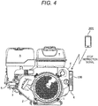
Fig. 4 is a view using a portable information terminal to issue a signal to stop operation of the general-purpose engine. - An information providing system according to an embodiment of the present invention will be described with reference to the drawings. It is supposed that each drawing is viewed in accordance with the direction of reference signs included therein.
-
Fig. 1 is a view showing a relation between a general-purpose engine and an operation permitting device which configure the information providing system according to the present invention. As shown inFig. 1 , theoperation permitting device 100 can be removably mounted on the general-purpose engine E. The general-purpose engine E cannot be started unless theoperation permitting device 100 is mounted on the general-purpose engine E. The general-purpose engine E which can be operated by theoperation permitting device 100 is associated with theoperation permitting device 100 in advance. Information about use of the general-purpose engine E based on an operation history of the associated general-purpose engine E is provided to a predetermined destination associated with a user of theoperation permitting device 100. The general-purpose engine E is used as a power source of an industrial small-sized working machine, for example, for an agriculture field or a construction field. - As shown in
Fig. 1 , the general-purpose engine E includes acrankcase 2, acylinder block 3 and acylinder head 5. Thecrankcase 2 includes aninstallation flange 1 at its bottom portion. Thecylinder block 3 is inclined and extends from one side of thecrankcase 2. Thecylinder head 5 is fitted to an end surface of thecylinder block 3 through a gasket. A fuel tank T is attached to an upper portion of thecrankcase 2. An air cleaner A is attached to an upper portion of thecylinder block 3. Theinstallation flange 1 is installed in a working machine which uses the general-purpose engine E as its power source. - A
receptacle 6 for mounting theoperation permitting device 100 on the general-purpose engine E is attached to the other side of thecrankcase 2 of the general-purpose engine E. A terminal (not shown) which can be connected to a terminal (not shown) provided in a back surface of theoperation permitting device 100 is provided in an inner part of areception space 6s of thereceptacle 6. When theoperation permitting device 100 is inserted into thereception space 6s of thereceptacle 6 to make the terminals electrically connected to each other, electric signals can be mutually transmitted between an Electric Control Unit (ECU) controlling operation of the general-purpose engine E and a Central Processing Unit (CPU) of theoperation permitting device 100, and electric power can be supplied from theoperation permitting device 100 to the general-purpose engine E. When apower supply switch 105 provided in a front surface of theoperation permitting device 100 is operated on this occasion, the general-purpose engine E starts, and anindicator 107 of theoperation permitting device 100 performs lighting. - An internal configuration of the general-purpose engine E and an internal configuration of the
operation permitting device 100, and a relation therebetween will be described below with reference toFig. 2 . - First, the internal configuration of the general-purpose engine E will be described. A
piston 14 is received reciprocatably in a cylinder (steam cylinder) 12 formed in thecylinder block 3 of the general-purpose engine 10. Thecylinder head 5 is attached to thecylinder block 3, and acombustion chamber 16 is formed between thecylinder head 5 and a top portion of thepiston 14. Asuction pipe 20 is connected to thecombustion chamber 16. A throttle valve 22 is disposed in thesuction pipe 20, and aninjector 24 is disposed in the vicinity of a suction port on a downstream side of the throttle valve 22. Theinjector 24 is connected to the fuel tank T through a fuel supply pipe 26. - Specifically, the
injector 24 is connected to asub fuel tank 32 through a first fuel supply pipe 26a, and thesub fuel tank 32 is connected to the fuel tank T through a second fuel supply pipe 26b. Alow pressure pump 34 is inserted in the second fuel supply pipe 26b to pump up fuel (gasoline) reserved in the fuel tank T to pneumatically supply the fuel to thesub fuel tank 32. A fuel pump (high pressure pump) 36 is disposed in thesub fuel tank 32. - The
fuel pump 36 pressurizes the fuel filtered by afilter 32a to high pressure to supply the fuel to theinjector 24 through the first fuel supply pipe 26a while aregulator 32b regulates the pressure of the fuel. The fuel of thesub fuel tank 32 is partially returned to the fuel tank T through areturn pipe 26c. - Intake air suctioned from the air cleaner A flows through the
suction pipe 20. After a flow rate of the intake air is adjusted by the throttle valve 22, the intake air reaches the suction port where the intake air is mixed with fuel injected from theinjector 24 to thereby form a fuel-air mixture. When asuction valve 40 is opened, the fuel-air mixture flows into thecombustion chamber 16 to be ignited by a spark plug 42 and combusted so as to drive thepiston 14. When anexhaust valve 44 is opened, exhaust gas generated due to the combustion flows through anexhaust pipe 46 so as to be released to the outside. - An electric motor (an actuator, specifically, a stepping motor) 64 is coupled to the throttle valve 22. The electric motor 64 is configured to open and close the throttle valve 22 independently of operation of an accelerator lever (not shown). That is, the throttle valve 22 is formed as a drive-by-wire type.
- Respective operations of the
fuel pump 36, theregulator 32b, theinjector 24, the spark plug 42, and the electric motor 64 which have been described above are controlled by the Electric Control Unit (ECU) 80 of the general-purpose engine 10. TheECU 80 can perform communication of electric signals with an external device (the operation permitting device 100) through the terminal of thereceptacle 6. Incidentally, supply of electric power to theECU 80, thefuel pump 36, theregulator 32b, theinjector 24 and the spark plug 42 can be performed also from theoperation permitting device 100 through the terminal of thereceptacle 6. Therefore, at a start of the general-purpose engine E, electric power is supplied from theoperation permitting device 100 to the power-source-requiring components when theoperation permitting device 100 is mounted on thereceptacle 6. Incidentally, electric power obtained by a power generating coil (not shown) provided in the general-purpose engine E is supplied to the power-source-requiring components after the start of the general-purpose engine E. - Next, the internal configuration of the
operation permitting device 100 will be described. Theoperation permitting device 100 includes amemory 101, awireless unit 103, apower switch 105, anindicator 107, asecondary battery 109, abooster circuit 111, acharger circuit 113, and a Central Processing Unit (CPU) 115. - The
memory 101 stores user information of theoperation permitting device 100, and information about the general-purpose engine E associated with theoperation permitting device 100 in advance. The user information of theoperation permitting device 100 includes a destination associated with the user of theoperation permitting device 100. The information about the general-purpose engine E includes individual information of the general-purpose engine E. Further, an operation history of the general-purpose engine E is recorded in thememory 101 by theCPU 115. The operation history includes not only a history of an operating time of the general-purpose engine E but also histories of a torque representing the magnitude of a load on the general-purpose engine E in operation, a rotation speed, temperature, or the like. - The
wireless unit 103 performs wireless communication, for example, with a portable information terminal owned by the user of theoperation permitting device 100. Thepower switch 105 is operated to start the general-purpose engine E or stop operation of the general-purpose engine E. When thepower switch 105 is operated in a state where theoperation permitting device 100 is mounted on the general-purpose engine E, the general-purpose engine E starts or stops. Theindicator 107 performs lighting or blinking in accordance with the state of the general-purpose engine E. - The
secondary battery 109 is a chargeable and dischargeable lithium-ion battery which, for example, outputs a voltage of about 3.7 V. Thebooster circuit 111 boosts an output voltage of thesecondary battery 109, for example, to 12 V. The voltage boosted by thebooster circuit 111 is supplied to the components, which require a power source at the start of the general-purpose engine E, through the terminal of thereceptacle 6 of the general-purpose engine E when theoperation permitting device 100 is mounted on the general-purpose engine E. When theoperation permitting device 100 removed from the general-purpose engine E is connected to an external power source through a cable or the like, thecharger circuit 113 charges thesecondary battery 109 which is low in charging state. - The
CPU 115 controls operations of theoperation permitting device 100 including the boosting operation of thebooster circuit 111, the charging operation of thecharger circuit 113, or the like. When theoperation permitting device 100 is mounted on the general-purpose engine E, theCPU 115 can perform communication of electric signals with theECU 80 of the general-purpose engine E through the terminal of thereceptacle 6 of the general-purpose engine E. Once theoperation permitting device 100 is mounted on the general-purpose engine E, theCPU 115 starts the boosting operation of thebooster circuit 111 when the individual information obtained from theECU 80 of the general-purpose engine E in response to a request matches with the information about the general-purpose engine E recorded in thememory 101. Thebooster circuit 111 does not have to perform the boosting operation when the general-purpose engine E can be operated by the output voltage of thesecondary battery 109. - Next, provision of the information about the use of the general-purpose engine E based on the operation history of the general-purpose engine E will be described with reference to
Fig. 3 . - In an example of
Fig. 3 , the user information of theoperation permitting device 100 and the operation history of the general-purpose engine E are transmitted to aserver 205 through aportable information terminal 201 and anetwork 203 when theoperation permitting device 100 is mounted on the general-purpose engine E. Theportable information terminal 201 is owned by the user of theoperation permitting device 100. Theserver 205 provides the information about the use of the general-purpose engine E to the predetermined destination included in the user information of theoperation permitting device 100 based on the operation history of the general-purpose engine E. The predetermined destination is, for example, an address of an electronic mail which the user can browse by theportable information terminal 201 or identification information unique to a terminal on a web network. - The contents of the information provided by the
server 205 are different depending on a rank which is set for each user of theoperation permitting device 100. That is, theserver 205 selects information of contents which are different depending on the rank included in the user information of theoperation permitting device 100, and transmits the selected information to the predetermined destination. For example, it is assumed that the information to be provided by theserver 205 is maintenance information of the general-purpose engine E. In this case, theserver 205 provides detailed maintenance information to the user when the user is set at a high rank who has high level of knowledge or attention about the maintenance or the like of the general-purpose engine E. On the other hand, theserver 205 provides minimum maintenance information, which is easy to understand, to the user when the user is set at a low rank who has low level of the aforementioned knowledge or attention. - Incidentally, the example shown in
Fig. 3 shows a state where theoperation permitting device 100 is mounted on the general-purpose engine E. Even when theoperation permitting device 100 is not mounted on the general-purpose engine E, theoperation permitting device 100 still can make communication with theportable information terminal 201. The predetermined destination to which the information about the use of the general-purpose engine E is provided may be stored in advance by theserver 205 in association with the user information of theoperation permitting device 100. - According to the embodiment as described above, the
operation permitting device 100 transmits the user information of theoperation permitting device 100 and the operation history of the associated general-purpose engine E to theserver 205. Theserver 205 provides the information of maintenance or the like about the use of the general-purpose engine E to the predetermined destination based on the transmitted operation history. Therefore, when the user of theoperation permitting device 100 browses the information provided to the predetermined destination, the user can refer to the information of the maintenance or the like about the use of the general-purpose engine E suitably. - Further, the contents of the information about the use of the general-purpose engine E are different depending on the rank of the user of the
operation permitting device 100. For example, detailed maintenance information is provided to the user when the user has high level of knowledge or attention about the maintenance or the like of the general-purpose engine E, while minimum maintenance information easy to understand is provided to the user when the user has low level of the knowledge or attention. Accordingly, information with suitable contents can be provided to the user. - Incidentally, the present invention is not limited to the above-described embodiment. Any modification, improvement or the like can be made on the present invention suitably. For example, the number of general-purpose engines E which can be operated using the
operation permitting device 100 is not limited to one but may be plural. In this case, pieces of individual information of general-purpose engines E which can be operated are registered as pieces of information about the general-purpose engines E in thememory 101 of theoperation permitting device 100. Among the general-purpose engines E which can be operated, only a general-purpose engine E on which theoperation permitting device 100 is mounted is allowed to be started. The general-purpose engines E which can be operated are not limited according to the individual engines but may be limited according to types such as models of engines. - When a plurality of general-purpose engines E which can be operated are registered for one
operation permitting device 100, respective operation histories of the general-purpose engines E which can be operated are recorded in thememory 101 of theoperation permitting device 100. TheCPU 115 of theoperation permitting device 100 may limit start of a general-purpose engine E which is highest in operation rate, based on the respective operation histories of the general-purpose engines E recorded in thememory 101. Accordingly, the start of the general-purpose engine E which is highest in operation rate is limited when there is a deviation in the operation rate among the general-purpose engines E based on the respective operation histories of the general-purpose engines E. Thus, the operation rates of the general-purpose engines E can be made approximately equal to one another. - The
portable information terminal 201 shown inFig. 3 serves as a proxy for thewireless unit 103 of theoperation permitting device 100 which is connected to thenetwork 203. The user can browse the information provided to the predetermined destination from theserver 205. The user of theoperation permitting device 100 may use theportable information terminal 201 to perform operation to stop operation of the general-purpose engine E. As shown inFig. 4 , theportable information terminal 201 on which the operation is performed transmits a stop instruction signal to theoperation permitting device 100, and thewireless unit 103 of theoperation permitting device 100 receives the signal. The stop instruction signal received by thewireless unit 103 is sent to theCPU 115. TheCPU 115 transmits the signal to theECU 80 of the general-purpose engineE. The ECU 80 stops control for operation of the general-purpose engine E in accordance with the stop instruction signal transmitted from theoperation permitting device 100. As a result, the general-purpose engine E stops operating. -
- E
- General-purpose engine
- 1
- Flange
- 2
- Crankcase
- 3
- Cylinder block
- 5
- Cylinder head
- 6
- Receptacle
- T
- Fuel tank
- A
- Air cleaner
- 12
- Cylinder
- 14
- Piston
- 16
- Combustion chamber
- 20
- Suction pipe
- 22
- Throttle valve
- 24
- Injector
- 26
- Fuel supply pipe
- 26a
- First fuel supply pipe
- 26b
- Second fuel supply pipe
- 26c
- Return pipe
- 32
- Sub fuel tank
- 32a
- Filter
- 32b
- Regulator
- 34
- Low pressure pump
- 36
- Fuel pump
- 40
- Suction valve
- 42
- Spark plug
- 44
- Exhaust valve
- 46
- Exhaust pipe
- 64
- Electric motor
- 80
- ECU
- 100
- Operation permitting device
- 101
- Memory
- 103
- Wireless unit
- 105
- Power switch
- 107
- Indicator
- 109
- Secondary battery
- 111
- Booster circuit
- 113
- Charger circuit
- 115
- CPU
- 201
- Portable information terminal
- 203
- Network
- 205
- Server
Claims (5)
- An information providing system about an internal combustion engine, the system comprising:an internal combustion engine which includes an electronic control type fuel injecting device;an operation permitting device which can be removably mounted on the internal combustion engine, wherein while the operation permitting device is mounted on the internal combustion engine which is associated with the operation permitting device in advance, the operation permitting device supplies electric power to the fuel injecting device at a start of the internal combustion engine; andan information providing device which provides information about use of the internal combustion engine to a destination associated with a user of the operation permitting device, based on an operation history of the associated internal combustion engine,wherein the operation permitting device includes a transmission unit which transmits, to the information providing device, user information of the operation permitting device and the operation history of the associated internal combustion engine.
- The information providing system according to claim 1,
wherein contents of the information about the use of the internal combustion engine provided by the information providing device are different depending on a rank which is set for each user. - The information providing system according to claim 1 or 2,
wherein the operation permitting device is registered to be allowed to operate a plurality of internal combustion engines, and
wherein among the plurality of internal combustion engines, only an internal combustion engine on which the operation permitting device is mounted is permitted to be started. - The information providing system according to claim 3,
wherein the operation permitting device limits start of an internal combustion engine which is highest in operation rate based on respective operation histories of the plurality of internal combustion engines. - The information providing system according to any one of claims 1 to 4,
wherein the operation permitting device includes an instruction receiving unit which receives, from the outside, a stop instruction to stop operation of the internal combustion engine, and
wherein the internal combustion engine on which the operation permitting device is mounted stops operation when the stop instruction is received by the instruction receiving unit.
Applications Claiming Priority (1)
| Application Number | Priority Date | Filing Date | Title |
|---|---|---|---|
| PCT/JP2017/013853 WO2018179444A1 (en) | 2017-03-31 | 2017-03-31 | Information providing system |
Publications (2)
| Publication Number | Publication Date |
|---|---|
| EP3591588A1 true EP3591588A1 (en) | 2020-01-08 |
| EP3591588A4 EP3591588A4 (en) | 2020-04-22 |
Family
ID=63674909
Family Applications (1)
| Application Number | Title | Priority Date | Filing Date |
|---|---|---|---|
| EP17904331.0A Withdrawn EP3591588A4 (en) | 2017-03-31 | 2017-03-31 | INFORMATION DELIVERY SYSTEM |
Country Status (5)
| Country | Link |
|---|---|
| US (1) | US11536217B2 (en) |
| EP (1) | EP3591588A4 (en) |
| JP (1) | JP6457665B1 (en) |
| CN (1) | CN110383304A (en) |
| WO (1) | WO2018179444A1 (en) |
Family Cites Families (25)
| Publication number | Priority date | Publication date | Assignee | Title |
|---|---|---|---|---|
| US5253159A (en) * | 1991-06-28 | 1993-10-12 | Square D Company | Electrical distribution system having controller responsive to multiple command paths |
| WO2003021099A1 (en) | 2001-08-29 | 2003-03-13 | Bosch Automotive Systems Corporation | Method and device for controlling operation of fuel injector |
| JP4771630B2 (en) | 2001-09-14 | 2011-09-14 | 株式会社スター精機 | Unloader abnormality diagnosis method |
| JP2004118471A (en) * | 2002-09-26 | 2004-04-15 | Mitsubishi Heavy Ind Ltd | Lease business support system |
| JP4136649B2 (en) * | 2002-12-26 | 2008-08-20 | トヨタ自動車株式会社 | Vehicle antitheft device and vehicle control method |
| DE10331240A1 (en) | 2003-07-10 | 2005-02-17 | Robert Bosch Gmbh | Method and control device for controlling a start-stop operation of an internal combustion engine |
| JP2005196399A (en) * | 2004-01-06 | 2005-07-21 | Hitachi Constr Mach Co Ltd | Construction machine management system, management method, management program, and computer-readable recording medium recording the management program |
| JP2005248481A (en) * | 2004-03-02 | 2005-09-15 | Eebiggu:Kk | Construction vehicle operating status monitoring device |
| JP2007138713A (en) | 2005-11-14 | 2007-06-07 | Yanmar Co Ltd | Internal combustion engine |
| JP4685600B2 (en) * | 2005-11-14 | 2011-05-18 | ヤンマー株式会社 | Ship navigation management system |
| JP4917457B2 (en) | 2007-03-09 | 2012-04-18 | 富士通株式会社 | Catch certification processing method, processing device, processing program, and processing system |
| US8065342B1 (en) * | 2008-02-22 | 2011-11-22 | BorgSolutions, Inc. | Method and system for monitoring a mobile equipment fleet |
| JP2011181079A (en) | 2011-03-28 | 2011-09-15 | Yanmar Co Ltd | System for managing marine internal combustion engine |
| US8935999B2 (en) | 2011-11-10 | 2015-01-20 | Toyota Jidosha Kabushiki Kaisha | Control device for internal combustion engine |
| US9816897B2 (en) * | 2012-06-06 | 2017-11-14 | Harris Corporation | Wireless engine monitoring system and associated engine wireless sensor network |
| JP2014015881A (en) | 2012-07-06 | 2014-01-30 | Honda Motor Co Ltd | Operation control device of internal combustion engine, operation control information providing system, and operation control information providing program |
| JP2014038437A (en) * | 2012-08-14 | 2014-02-27 | Kubota Corp | Ground work management system and ground work machine used therein |
| US8751065B1 (en) * | 2012-12-14 | 2014-06-10 | Denso Corporation | Smartphone controller of vehicle settings |
| WO2014144036A1 (en) * | 2013-03-15 | 2014-09-18 | Angel Enterprise Systems, Inc. | Engine analysis and diagnostic system |
| US10060827B2 (en) * | 2014-01-17 | 2018-08-28 | Kohler Co. | Fleet management system |
| CN105960573B (en) | 2014-02-07 | 2020-07-24 | 日产自动车株式会社 | vehicle information providing device |
| JP6450961B2 (en) * | 2014-03-27 | 2019-01-16 | セイコーエプソン株式会社 | Information communication system, information processing apparatus, and information providing method |
| JP6280854B2 (en) * | 2014-10-07 | 2018-02-14 | ヤンマー株式会社 | Work plan information transmission method |
| JP6533903B2 (en) * | 2014-11-12 | 2019-06-26 | 株式会社ユピテル | Remote controller and system for in-vehicle devices |
| US10378994B2 (en) * | 2015-03-05 | 2019-08-13 | Ai Alpine Us Bidco Inc. | Wireless vibration monitoring of movable engine parts |
-
2017
- 2017-03-31 JP JP2017562107A patent/JP6457665B1/en not_active Expired - Fee Related
- 2017-03-31 EP EP17904331.0A patent/EP3591588A4/en not_active Withdrawn
- 2017-03-31 WO PCT/JP2017/013853 patent/WO2018179444A1/en not_active Ceased
- 2017-03-31 CN CN201780088066.2A patent/CN110383304A/en not_active Withdrawn
- 2017-03-31 US US16/497,947 patent/US11536217B2/en active Active
Also Published As
| Publication number | Publication date |
|---|---|
| CN110383304A (en) | 2019-10-25 |
| US20200408166A1 (en) | 2020-12-31 |
| EP3591588A4 (en) | 2020-04-22 |
| JPWO2018179444A1 (en) | 2019-04-04 |
| JP6457665B1 (en) | 2019-01-23 |
| US11536217B2 (en) | 2022-12-27 |
| WO2018179444A1 (en) | 2018-10-04 |
Similar Documents
| Publication | Publication Date | Title |
|---|---|---|
| US11655779B2 (en) | Thermal choke, autostart generator system, and method of use thereof | |
| KR101232711B1 (en) | Educational device for training electronic control system of automobile engine | |
| US20150025775A1 (en) | Fuel mixture system and assembly | |
| US10961969B2 (en) | Startup assistance device for internal combustion engine | |
| US20150020770A1 (en) | Fuel mixture system and assembly | |
| CN101639013A (en) | Fuel delivery system for a multi-fuel engine | |
| US11274613B2 (en) | Engine control system and method | |
| CN106194451A (en) | The method that multifuel engine and multifuel engine are run | |
| US11536217B2 (en) | Information providing system | |
| CN101280727A (en) | Engine | |
| US11526592B2 (en) | Working machine management system and working machine | |
| EP1813806A1 (en) | Fuel injection and ignition system with starting and auxiliary batteries | |
| CN202033658U (en) | Measurement and control system using oil field and coalfield associated gas as power and used for oil pumping unit and air exhauster | |
| GB2459715A (en) | Mobile Engine Testing Apparatus | |
| US11486329B2 (en) | Load operating device | |
| US10774765B2 (en) | Method for starting a combustion engine having a starter apparatus | |
| US7826955B2 (en) | General-purpose internal combustion engine | |
| Kinnen et al. | Electronically controlled batteryless injection system for small two-stroke SI engines | |
| EP3376018A2 (en) | System and method for positioning a crankshaft of an engine of a vehicle | |
| RU2008143341A (en) | METHOD AND DEVICE FOR TRANSFORMING A GASOLINE INTERNAL COMBUSTION ENGINE TO A FUEL ENGINE WITHOUT COMBUSTION OF FUEL | |
| KR840000734B1 (en) | Fuel supply control device of internal combustion engine | |
| US20200332758A1 (en) | Electronic ignition system for a generator engine | |
| Zahn et al. | Electronic Fuel Injection System for Handheld Working Equipment | |
| WO2018013567A1 (en) | Starting system for internal combustion engine with electronic fuel injection system or advanced induction ignition system |
Legal Events
| Date | Code | Title | Description |
|---|---|---|---|
| STAA | Information on the status of an ep patent application or granted ep patent |
Free format text: STATUS: THE INTERNATIONAL PUBLICATION HAS BEEN MADE |
|
| PUAI | Public reference made under article 153(3) epc to a published international application that has entered the european phase |
Free format text: ORIGINAL CODE: 0009012 |
|
| STAA | Information on the status of an ep patent application or granted ep patent |
Free format text: STATUS: REQUEST FOR EXAMINATION WAS MADE |
|
| 17P | Request for examination filed |
Effective date: 20190930 |
|
| AK | Designated contracting states |
Kind code of ref document: A1 Designated state(s): AL AT BE BG CH CY CZ DE DK EE ES FI FR GB GR HR HU IE IS IT LI LT LU LV MC MK MT NL NO PL PT RO RS SE SI SK SM TR |
|
| AX | Request for extension of the european patent |
Extension state: BA ME |
|
| A4 | Supplementary search report drawn up and despatched |
Effective date: 20200323 |
|
| RIC1 | Information provided on ipc code assigned before grant |
Ipc: G06Q 10/00 20120101AFI20200317BHEP |
|
| DAV | Request for validation of the european patent (deleted) | ||
| DAX | Request for extension of the european patent (deleted) | ||
| STAA | Information on the status of an ep patent application or granted ep patent |
Free format text: STATUS: EXAMINATION IS IN PROGRESS |
|
| 17Q | First examination report despatched |
Effective date: 20201222 |
|
| STAA | Information on the status of an ep patent application or granted ep patent |
Free format text: STATUS: THE APPLICATION IS DEEMED TO BE WITHDRAWN |
|
| 18D | Application deemed to be withdrawn |
Effective date: 20221103 |