EP3591513A1 - Display control device, method of controlling display, and storage medium - Google Patents
Display control device, method of controlling display, and storage medium Download PDFInfo
- Publication number
- EP3591513A1 EP3591513A1 EP17899019.8A EP17899019A EP3591513A1 EP 3591513 A1 EP3591513 A1 EP 3591513A1 EP 17899019 A EP17899019 A EP 17899019A EP 3591513 A1 EP3591513 A1 EP 3591513A1
- Authority
- EP
- European Patent Office
- Prior art keywords
- working machine
- state
- processing apparatus
- automatic working
- display
- Prior art date
- Legal status (The legal status is an assumption and is not a legal conclusion. Google has not performed a legal analysis and makes no representation as to the accuracy of the status listed.)
- Ceased
Links
Images






Classifications
-
- G—PHYSICS
- G05—CONTROLLING; REGULATING
- G05D—SYSTEMS FOR CONTROLLING OR REGULATING NON-ELECTRIC VARIABLES
- G05D1/00—Control of position, course, altitude or attitude of land, water, air or space vehicles, e.g. using automatic pilots
- G05D1/0011—Control of position, course, altitude or attitude of land, water, air or space vehicles, e.g. using automatic pilots associated with a remote control arrangement
- G05D1/0044—Control of position, course, altitude or attitude of land, water, air or space vehicles, e.g. using automatic pilots associated with a remote control arrangement by providing the operator with a computer generated representation of the environment of the vehicle, e.g. virtual reality, maps
-
- G—PHYSICS
- G06—COMPUTING OR CALCULATING; COUNTING
- G06F—ELECTRIC DIGITAL DATA PROCESSING
- G06F3/00—Input arrangements for transferring data to be processed into a form capable of being handled by the computer; Output arrangements for transferring data from processing unit to output unit, e.g. interface arrangements
- G06F3/14—Digital output to display device ; Cooperation and interconnection of the display device with other functional units
- G06F3/147—Digital output to display device ; Cooperation and interconnection of the display device with other functional units using display panels
-
- A—HUMAN NECESSITIES
- A01—AGRICULTURE; FORESTRY; ANIMAL HUSBANDRY; HUNTING; TRAPPING; FISHING
- A01D—HARVESTING; MOWING
- A01D34/00—Mowers; Mowing apparatus of harvesters
- A01D34/006—Control or measuring arrangements
- A01D34/008—Control or measuring arrangements for automated or remotely controlled operation
-
- G—PHYSICS
- G06—COMPUTING OR CALCULATING; COUNTING
- G06F—ELECTRIC DIGITAL DATA PROCESSING
- G06F3/00—Input arrangements for transferring data to be processed into a form capable of being handled by the computer; Output arrangements for transferring data from processing unit to output unit, e.g. interface arrangements
- G06F3/01—Input arrangements or combined input and output arrangements for interaction between user and computer
- G06F3/048—Interaction techniques based on graphical user interfaces [GUI]
- G06F3/0484—Interaction techniques based on graphical user interfaces [GUI] for the control of specific functions or operations, e.g. selecting or manipulating an object, an image or a displayed text element, setting a parameter value or selecting a range
- G06F3/04845—Interaction techniques based on graphical user interfaces [GUI] for the control of specific functions or operations, e.g. selecting or manipulating an object, an image or a displayed text element, setting a parameter value or selecting a range for image manipulation, e.g. dragging, rotation, expansion or change of colour
-
- G—PHYSICS
- G06—COMPUTING OR CALCULATING; COUNTING
- G06F—ELECTRIC DIGITAL DATA PROCESSING
- G06F3/00—Input arrangements for transferring data to be processed into a form capable of being handled by the computer; Output arrangements for transferring data from processing unit to output unit, e.g. interface arrangements
- G06F3/14—Digital output to display device ; Cooperation and interconnection of the display device with other functional units
-
- G—PHYSICS
- G06—COMPUTING OR CALCULATING; COUNTING
- G06F—ELECTRIC DIGITAL DATA PROCESSING
- G06F3/00—Input arrangements for transferring data to be processed into a form capable of being handled by the computer; Output arrangements for transferring data from processing unit to output unit, e.g. interface arrangements
- G06F3/14—Digital output to display device ; Cooperation and interconnection of the display device with other functional units
- G06F3/1423—Digital output to display device ; Cooperation and interconnection of the display device with other functional units controlling a plurality of local displays, e.g. CRT and flat panel display
-
- G—PHYSICS
- G06—COMPUTING OR CALCULATING; COUNTING
- G06F—ELECTRIC DIGITAL DATA PROCESSING
- G06F3/00—Input arrangements for transferring data to be processed into a form capable of being handled by the computer; Output arrangements for transferring data from processing unit to output unit, e.g. interface arrangements
- G06F3/14—Digital output to display device ; Cooperation and interconnection of the display device with other functional units
- G06F3/1454—Digital output to display device ; Cooperation and interconnection of the display device with other functional units involving copying of the display data of a local workstation or window to a remote workstation or window so that an actual copy of the data is displayed simultaneously on two or more displays, e.g. teledisplay
-
- G—PHYSICS
- G07—CHECKING-DEVICES
- G07C—TIME OR ATTENDANCE REGISTERS; REGISTERING OR INDICATING THE WORKING OF MACHINES; GENERATING RANDOM NUMBERS; VOTING OR LOTTERY APPARATUS; ARRANGEMENTS, SYSTEMS OR APPARATUS FOR CHECKING NOT PROVIDED FOR ELSEWHERE
- G07C5/00—Registering or indicating the working of vehicles
- G07C5/008—Registering or indicating the working of vehicles communicating information to a remotely located station
-
- H—ELECTRICITY
- H04—ELECTRIC COMMUNICATION TECHNIQUE
- H04W—WIRELESS COMMUNICATION NETWORKS
- H04W4/00—Services specially adapted for wireless communication networks; Facilities therefor
- H04W4/30—Services specially adapted for particular environments, situations or purposes
- H04W4/40—Services specially adapted for particular environments, situations or purposes for vehicles, e.g. vehicle-to-pedestrians [V2P]
-
- A—HUMAN NECESSITIES
- A01—AGRICULTURE; FORESTRY; ANIMAL HUSBANDRY; HUNTING; TRAPPING; FISHING
- A01D—HARVESTING; MOWING
- A01D2101/00—Lawn-mowers
-
- G—PHYSICS
- G09—EDUCATION; CRYPTOGRAPHY; DISPLAY; ADVERTISING; SEALS
- G09G—ARRANGEMENTS OR CIRCUITS FOR CONTROL OF INDICATING DEVICES USING STATIC MEANS TO PRESENT VARIABLE INFORMATION
- G09G2370/00—Aspects of data communication
- G09G2370/16—Use of wireless transmission of display information
-
- G—PHYSICS
- G09—EDUCATION; CRYPTOGRAPHY; DISPLAY; ADVERTISING; SEALS
- G09G—ARRANGEMENTS OR CIRCUITS FOR CONTROL OF INDICATING DEVICES USING STATIC MEANS TO PRESENT VARIABLE INFORMATION
- G09G2380/00—Specific applications
- G09G2380/06—Remotely controlled electronic signs other than labels
Definitions
- the present invention relates to a display control apparatus, a display control method, and a storage medium.
- Patent Literature 1 (PTL 1) describes a technology in which a user can confirm a work area map created by an automatic working machine using an external device.
- One aspect of the present invention allows a user to intuitively understand the state of the automatic working machine.
- a storage medium storing a program
- the program including instructions for causing, when executed by at least one processor, the at least one processor to execute: acquiring a state of an automatic working machine; and displaying an image illustrating the automatic working machine in a display apparatus in a size in accordance with the state.
- the automatic working machine refers to an apparatus that performs work without requiring real-time instructions from a user.
- the automatic working machine may perform work in accordance with a predetermined procedure.
- the automatic working machine may be an autonomously travelling type. This type of the automatic working machine may also be referred to as an unmanned working vehicle.
- a mobile lawnmower that performs lawn mowing work will be described as an example of the unmanned working vehicle.
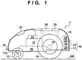
- FIG. 1 is a side view schematically illustrating a configuration of an automatic working machine (hereinafter, simply referred to as a working machine) according to some embodiments
- FIG. 2 is a plan view.
- the rectilinear direction (length direction) and the vehicle width direction perpendicular to the rectilinear direction of the working machine in planer view are respectively defined as a front-and-rear direction and a left-and-right direction
- the height direction of the working machine is defined as an up-and-down direction
- the configuration of the units will be described in accordance with this definition.
- a working machine 1 includes a vehicle body 10 having a chassis 11 and a frame 12, and a left-and-right pair of front wheels 13 and a left-and-right pair of rear wheels 14 that support the vehicle body 10 from a ground plane GR such that the working machine 1 can travel.
- the front wheels 13 are rotatably attached to a front side of the chassis 11 via stays 11a.
- the rear wheels 14 have a larger diameter than the front wheels 13, and are rotatably attached directly to a rear side of the chassis 11.
- An input apparatus 25 and a display apparatus 26 are installed on an upper surface of the frame 12.
- the working machine 1 has a weight and a size that allows users to carry the working machine 1 by themselves.
- the total length (length in the front-and-rear direction), the total width, and the height of the working machine 1 are respectively about 500 mm, about 300 mm, and about 300 mm, for example.
- the input apparatus 25 is an apparatus for receiving an input operation made by the user, and includes a numerical keyboard, cursor keys, switches and the like.
- the switches include a main switch for instructing to start operations of the working machine 1 and an emergency stop switch for instructing an emergency stop, for example.
- the display apparatus 26 is an apparatus for providing various types of information to the user. The user can inputs various instructions via the input apparatus 25 (numerical keyboard, cursor keys) while viewing information displayed on the display apparatus 26.
- the input apparatus 25 and the display apparatus 26 can be constituted by a touch screen.
- a working apparatus 16 In an interior space 15 of the working machine 1 that is surrounded by the chassis 11 and the frame 12, a working apparatus 16, a working motor 17 for driving the working machine, a traveling motor 18 for driving rear wheels, a charging unit 19, a battery 20, a control apparatus 23, and a communication apparatus 24 are arranged.
- the working apparatus 16 includes a rotator and a lawn-mowing blade attached to the rotator, and has a substantially disc shape as a whole.
- the working apparatus 16 is configured such that a rotating shaft at the center of the rotator is arranged along an up-and-down direction, and the height of the blade from the ground plane GR can be adjusted by a height adjustment mechanism 21.
- the height adjustment mechanism 21 includes a screw that can be operated by the user, for example.
- the working motor 17 is constituted by a traveling motor that is arranged above the working apparatus 16, the output shaft thereof being coupled to the rotating shaft of the rotator, and rotationally drives the blade integrally with the rotator.
- the traveling motor 18 is constituted by a pair of traveling motors 18L and 18R that are respectively arranged inside, in the left and right direction, of the left and right rear wheels 14.
- the output shafts of the traveling motors 18L and 18R are respectively coupled to the rotating shafts of the left and right rear wheels 14, and the traveling motors 18L and 18R independently rotationally drive the left and right rear wheels 14. That is, the working machine 1 is configured such that the front wheels 13 are driven wheels and the rear wheels 14 are driving wheels, and the traveling motors 18L and 18R independently rotationally drive the left and right rear wheels 14 in a normal direction (rotation in a forward direction) or in a reverse direction (rotation in a backward direction). As a result of causing a speed difference in rotation between the left and right rear wheels 14, the working machine 1 can turn at any angle.
- the working machine 1 when the left and right rear wheels 14 are rotated in a normal direction, if the rotational speed of the right rear wheel 14 is higher than the rotational speed of the left rear wheel 14, the working machine 1 turns left at a turning angle in accordance with the speed difference. On the other hand, if the rotational speed of the left rear wheel 14 is higher than the rotational speed of the right rear wheel 14, the working machine 1 turns right at a turning angle in accordance with the speed difference. If one of the left and right rear wheels 14 is rotated in a normal direction, and the other is rotated in a reverse direction at the same speed, the working machine 1 turns on the spot.
- the charging unit 19 includes an AC/DC converter, and is connected to terminals 22 provided in a front end portion of the frame 12 via wiring, and is also connected to the battery 20 via wiring.
- the terminals 22 have contacts 22a, and as a result of the terminals 22 being connected to a charging station 3 (refer to FIG. 4 ) via the contacts 22a, the battery 20 can be charged.
- the battery 20 is connected to the working motor 17 and the traveling motor 18 via wiring, and the working motor 17 and the traveling motor 18 are driven with power supplied from the battery 20 via drivers. Also, power is also supplied to the control apparatus 23, the communication apparatus 24, the input apparatus 25, and the display apparatus 26 from the battery 20.
- a pair of magnetic sensors 51 are arranged in a front portion of the working machine 1 so as to be separated in the left-and-right direction. Specifically, as shown in FIG. 2 , the pair of magnetic sensors 51L and 51R are arranged symmetrically in the left-right direction relative to a central line CL that passes through the center of the working machine 1 in the vehicle width direction, along a rectilinear direction.
- the working machine 1 includes a yaw sensor, a G sensor, a direction sensor, a GPS sensor, a contact sensor, a left-and-right pair of wheel speed sensors, and a voltage sensor, in addition to the magnetic sensor 51.
- the magnetic sensor outputs a signal indicating the magnitude of magnetic field (magnetic field strength).
- the yaw sensor is an angular velocity sensor that outputs a signal indicating the angular velocity (yaw rate) about an axis (Z axis) in the height direction of the working machine 1.
- the control apparatus 23 can detect the turning angle of the working machine 1 about the Z axis with the signal from the yaw sensor.
- the G sensor outputs a signal indicating the accelerations in three orthogonal axes (X axis, Y axis, Z axis) directions that act on the working machine 1.
- the direction sensor is a geomagnetic sensor having a two-axis or three-axis structure that outputs a signal corresponding to the geomagnetism.
- the control apparatus 23 can detect the orientation of the working machine 1 relative to a predetermined direction (north, for example) with the signal from the direction sensor.
- the GPS sensor receives radio waves from GPS satellites, and detects the current position (latitude, longitude) of the working machine 1.
- the contact sensor outputs an ON signal when the working machine 1 approaches or comes in contact with an obstacle.
- the wheel speed sensors respectively output signals indicating the wheel speeds of the left and right rear wheels 14.
- the control apparatus 23 can calculate the traveling distance of the working machine 1 with the signals from the wheel speed sensors.
- the voltage sensor detects the residual voltage of the battery 20.
- the communication apparatus 24 is an apparatus for communicating with an apparatus external to the working machine 1, and is constituted by a transmitting and receiving antenna and a signal processing circuit for processing signals that are to be transmitted and have received via the transmitting and receiving antenna, for example.
- the communication apparatus 24 may conform to a near field communication technology such as a wireless LAN or Bluetooth, or may conform to a mobile communication technology such as 3G or LTE.
- the control apparatus 23 is an apparatus for controlling overall operations of the working machine 1, and is a microcomputer such as an ECU (electronic control unit), for example.
- the working machine 1 can communicate with an information processing apparatus 30 that is external to the working machine 1.
- An exemplary configuration of the control apparatus 23 and the information processing apparatus 30 will be described with reference to FIG. 3 . In FIG. 3 , some constituent elements of the working machine 1 are omitted.
- the control apparatus 23 includes a processing apparatus 27 and a storage apparatus 28.
- the processing apparatus 27 is an apparatus that executes processing to be performed by the control apparatus 23, and is constituted by a processor such as a CPU, for example.
- the storage apparatus 28 is an apparatus for storing data for processing to be performed by the control apparatus 23, and is constituted by a memory such as a RAM or a ROM.
- the storage apparatus 28 stores programs and data that define the operations of the working machine 1.
- the processing apparatus 27 updates data stored in the storage apparatus 28 based on a user input made through the input apparatus 25 or an input received from the information processing apparatus 30. Also, the processing apparatus 27 performs display control of the display apparatus 26 and operation control of the working motor 17 and the traveling motor 18 by executing instructions included in programs stored in the storage apparatus 28. When these types of control are executed, the processing apparatus 27 uses various types of data read out from the storage apparatus 28 and data acquired from the above-described various sensors that have been installed in the working machine 1.
- the information processing apparatus 30 is an apparatus for the user of the working machine 1 to remotely control the working machine 1, and may be a mobile apparatus such as a mobile phone terminal, a smartphone, or a laptop computer, or may be a stationary apparatus such as a desktop computer.
- the information processing apparatus 30 includes a processing apparatus 31, a storage apparatus 32, an input apparatus 33, a display apparatus 34, and a communication apparatus 35.
- the processing apparatus 31 is an apparatus for executing processing to be performed by the information processing apparatus 30, and is constituted by a processor such as a CPU, for example.
- the storage apparatus 32 is an apparatus for storing data for processing to be performed by the information processing apparatus 30, and is constituted by a memory such as a RAM or a ROM.
- the storage apparatus 32 stores programs and data that define the operations of the information processing apparatus 30. In some embodiments, the storage apparatus 32 stores programs as application programs.
- the processing apparatus 31 updates data stored in the storage apparatus 32 based on a user input made through the input apparatus 33 or an input received from the working machine 1. Also, the processing apparatus 31 performs display control of the display apparatus 34 and operation control of the working machine 1 by executing instructions included in programs stored in the storage apparatus 32.
- the input apparatus 33 is an apparatus for accepting an input operation made by the user, and includes a touch panel, a keyboard, and the like.
- the display apparatus 34 is an apparatus for providing various types of information to the user. The user can input various instructions through the input apparatus 33 while viewing information displayed in the display apparatus 34.
- the input apparatus 33 and the display apparatus 34 can be constituted by a touch screen.
- the communication apparatus 35 is an apparatus for communicating with an apparatus external to the information processing apparatus 30, and is constituted by a transmitting and receiving antenna and a signal processing circuit for processing signals that are to be transmitted and have been received via the transmitting and receiving antenna, for example.
- the communication apparatus 35 may conform to a near field communication technology such as a wireless LAN or Bluetooth, or may conform to a mobile communication technology such as 3G or LTE.
- FIG. 4 is a diagram illustrating an example of a work area AR.
- the work area AR is demarcated by an area wire 2 that has been laid in advance (buried in a predetermined depth from a ground plane GR, in advance), for example.
- the area wire 2 is laid such that a building on the site and an obstacle are not included, for example.
- a current is supplied to the area wire 2, and a magnetic field is generated due to this current in the work area AR.
- the charging station 3 is arranged on the area wire 2 for charging the battery 20.
- the work area AR defines the traveling range of the working machine 1, and may include a region in which the work is not to be performed, in addition to the region in which the work is to be performed.
- This method is performed by the processing apparatus 31 reading out a program (application program, for example) stored in the storage apparatus 32, and executing instructions included in the program. That is, when this method is executed, the information processing apparatus 30 functions as a display control apparatus. This method is started when the user of the information processing apparatus 30 starts an application program, for example.
- a program application program, for example
- step S501 the processing apparatus 31 generates a home screen of the application, and displays the home screen on the display apparatus 34.
- the home screen is a screen for visually illustrating the state of the working machine 1.
- FIG. 6 shows a home screen 600, which is an example of the home screen. Five buttons for switching the screen are arranged side by side on an upper side of the home screen 600.
- a button 601 is for displaying the home screen. The button 601 is displayed in a larger size than those of other buttons 602 to 605 in order to indicate that the currently selected screen is the home screen.
- the button 602 is for displaying a schedule setting screen.
- the user can set a work schedule of the working machine 1 on the schedule setting screen.
- the button 603 is a button for displaying a setting screen.
- the user can change settings regarding an application on the setting screen.
- the button 604 is a button for saving the current schedule setting and other settings in the storage apparatus 32.
- the button 605 is a button for displaying a screen for setting a cutting height of the lawn.
- the home screen 600 includes an image display region 606 at the center thereof. As will be described later, the state of the working machine 1 is displayed as an image in the image display region 606. Three buttons for the user to directly operate the working machine 1 are arranged side by side on a lower side of the home screen 600.
- a button 607 is a button for causing the working machine 1 on standby to start work.
- a button 608 is a button for opening a screen on which the user directly controls the travelling of the working machine 1.
- a button 609 is a button for causing the working machine 1 in operation to stop the work.
- the processing apparatus 31 acquires the state of the working machine 1.
- the state of the working machine 1 includes an operating state (such as being in operation or on standby, for example) of the working machine 1, information indicating whether or not an error has occurred in the working machine 1, a communication condition between the working machine 1 and the information processing apparatus 30, and the remaining amount of the battery 20, for example.
- the processing apparatus 31 determines the state of the working machine 1. For example, the processing apparatus 31 transmits a request for requesting transmission of information regarding the operating state of the working machine 1, whether or not an error has occurred, and the remaining amount of the battery 20, to the working machine 1.
- the processing apparatus 31 determines that the state of the working machine 1 is a "communication incapable state”. If a response from the working machine 1 has been received within the predetermined time, the processing apparatus 31 determines that the state of the working machine 1 is one of "in operation”, “on standby", and an "error state” based on the contents of communication from the working machine 1.
- step S504 the processing apparatus 31 updates the home screen that is currently displayed on the display apparatus 34 so as to display an image indicating being "in operation” in a standard size.
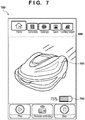
- FIG. 7 shows a home screen 700, which is an example of the home screen in the case of being "in operation”.
- An image 701 illustrating the working machine 1 is displayed in the image display region 606 of the home screen 700.
- the image 701 is an image in which the external appearance of the working machine 1 is illustrated in a form indicating that the working machine 1 is in operation, in a standard size.
- the image 701 may also be displayed as an animation for indicating that the working machine 1 is in operation.
- An image 702 indicating the remaining amount of the battery 20 is also displayed in the image display region 606.
- step S505 the processing apparatus 31 updates the home screen that is currently displayed on the display apparatus 34 so as to display an image indicating being “on standby” in a standard size.
- step S506 the processing apparatus 31 updates the home screen that is currently displayed in the display apparatus 34 so as to display an image indicating an "error state” in a small size.
- step S507 the processing apparatus 31 updates the home screen that is currently displayed in the display apparatus 34 so as to display an image indicating a "communication incapable state” in a small size.
- FIG. 8 shows a home screen 800, which is an example of the home screen in the case of a "communication incapable state".
- An image 801 illustrating the working machine 1 and an image 802 illustrating that the working machine 1 and the information processing apparatus 30 cannot communicate with each other are displayed in the image display region 606 of the home screen 800.
- the image 801 is an image in which the external appearance of the working machine 1 is illustrated in a form indicating that communication is impossible, in a small size.
- the small size used in steps S506 and S507 is a size that is smaller than the standard size.
- the small size may be 20% to 80% of the standard size, and may be half (50%).
- step S508 the processing apparatus 31 determines whether or not displaying of a screen other than the home screen has been selected by the user. If displaying of a screen other than the home screen has been selected by the user ("YES” in step S508), in step S509, the processing apparatus 31 displays the selected screen. If displaying of a screen other than the home screen has not been selected by the user ("NO” in step S508), the processing apparatus 31 returns the processing to step S502, and updates the home screen again.
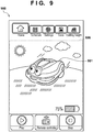
- a home screen 900 shown in FIG. 9 is displayed in step S504, and a home screen 1000 shown in FIG. 10 is displayed in step S507.
- An image 901, in the home screen 900, illustrating the working machine 1 and an image 1001, in the home screen 1000, illustrating the working machine 1 are images obtained by deforming the external appearance of the working machine 1.
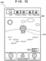
- a home screen 1100 shown in FIG. 11 is displayed in step S504, and a home screen 1200 shown in FIG. 12 is displayed in step S507.
- An image 1101, in the home screen 1100, illustrating the working machine 1 and an image 1201, in the home screen 1200, illustrating the working machine 1 are character images using the external appearance of the working machine 1 as a motif.
- This method is implemented by the processing apparatus 27 reading out a program stored in the storage apparatus 28 and executing instructions included in the program. That is, when this method is executed, the control apparatus 23 functions as a display control apparatus. This method is started when a power supply of the working machine 1 is turned on, for example.
- the processing apparatus 27 displays the home screen in the display apparatus 26 similarly to step S501.
- the home screen may be the same as the home screen 600 in FIG. 6 , or may include only the image display region 606 of the home screen 600.
- step S1302 the processing apparatus 27 acquires the state of the working machine 1.
- the state of the working machine 1 includes an operating state (such as being in operation or on standby, for example) of the working machine 1, information indicating whether or not an error has occurred in the working machine 1, and the remaining amount of the battery 20, for example.
- step S503 the processing apparatus 31 determines the state of the working machine 1. The processing apparatus 31 determines that the state of the working machine 1 is one of "in operation”, “on standby", and an "error state” based on data from the various sensors of the working machine 1 and data stored in the storage apparatus 28.
- the processing apparatus 31 updates the home screen that is currently displayed in the display apparatus 26 in steps S1304 to S1306, similarly to steps S504 to S506. Thereafter, the processing apparatus 31 performs processing in steps S1307 and S1308 that is similar to that in steps S508 and S509. As a result of displaying the image indicating the working machine 1 in the small size when the working machine 1 does not properly operate as in an "error state", the user of the working machine 1 can intuitively understand such a state by viewing the display apparatus 26 of the working machine 1.
- a storage medium (28, 32) storing a program, the program including instructions for causing, when executed by at least one processor (27, 31), the at least one processor to execute:
- the user can intuitively understand the state of the automatic working machine using the information processing apparatus.
- a display control apparatus (23, 30) comprising:
- a method comprising:
Landscapes
- Engineering & Computer Science (AREA)
- Theoretical Computer Science (AREA)
- General Engineering & Computer Science (AREA)
- Physics & Mathematics (AREA)
- General Physics & Mathematics (AREA)
- Human Computer Interaction (AREA)
- Radar, Positioning & Navigation (AREA)
- Remote Sensing (AREA)
- Life Sciences & Earth Sciences (AREA)
- Environmental Sciences (AREA)
- Computer Networks & Wireless Communication (AREA)
- Signal Processing (AREA)
- Aviation & Aerospace Engineering (AREA)
- Automation & Control Theory (AREA)
- Lifting Devices For Agricultural Implements (AREA)
- Digital Computer Display Output (AREA)
Abstract
Description
- The present invention relates to a display control apparatus, a display control method, and a storage medium.
- An automatic working machine is known that performs lawn mowing by autonomously travelling in a work area that is defined by an area wire. Patent Literature 1 (PTL 1) describes a technology in which a user can confirm a work area map created by an automatic working machine using an external device.
- PTL 1: Japanese Patent Laid-Open No.
2016-186748 - It is possible to confirm a work area map created by an automatic working machine with the technology described in
Patent Document 1. - However, it has been difficult for a user to intuitively understand the state of the automatic working machine. One aspect of the present invention allows a user to intuitively understand the state of the automatic working machine.
- According to some embodiments of the present invention, a storage medium storing a program is provided, the program including instructions for causing, when executed by at least one processor, the at least one processor to execute: acquiring a state of an automatic working machine; and displaying an image illustrating the automatic working machine in a display apparatus in a size in accordance with the state.
- A user can intuitively understand the state of the automatic working machine.
-
-
FIG. 1 is a side view schematically illustrating a configuration of a working machine according to an embodiment of the present invention. -
FIG. 2 is a plan view schematically illustrating the configuration of the working machine according to the embodiment of the present invention. -
FIG. 3 is a block diagram illustrating a configuration of a control apparatus and an information processing apparatus of the working machine according to the embodiment of the present invention. -
FIG. 4 is a diagram illustrating an example of a work area in which work is performed by the working machine according to the embodiment of the present invention. -
FIG. 5 is a flow diagram illustrating an example of operations of the information processing apparatus according to the embodiment of the present invention. -
FIG. 6 is a diagram illustrating an exemplary display screen of the information processing apparatus according to the embodiment of the present invention. -
FIG. 7 is a diagram illustrating an exemplary display screen of the information processing apparatus according to the embodiment of the present invention. -
FIG. 8 is a diagram illustrating an exemplary display screen of the information processing apparatus according to the embodiment of the present invention. -
FIG. 9 is a diagram illustrating an exemplary display screen of the information processing apparatus according to the embodiment of the present invention. -
FIG. 10 is a diagram illustrating an exemplary display screen of the information processing apparatus according to the embodiment of the present invention. -
FIG. 11 is a diagram illustrating an exemplary display screen of the information processing apparatus according to the embodiment of the present invention. -
FIG. 12 is a diagram illustrating an exemplary display screen of the information processing apparatus according to the embodiment of the present invention. -
FIG. 13 is a flow diagram illustrating an example of operations of the working machine according to the embodiment of the present invention. - Embodiments of the present invention will be described with reference to the accompanying drawings. The same reference signs are given to similar elements throughout the various embodiments, and redundant description will be omitted. Also, the embodiments can be changed or combined as appropriate. Some embodiments of the present invention relate to an automatic working machine. The automatic working machine refers to an apparatus that performs work without requiring real-time instructions from a user. The automatic working machine may perform work in accordance with a predetermined procedure. The automatic working machine may be an autonomously travelling type. This type of the automatic working machine may also be referred to as an unmanned working vehicle. In the following, a mobile lawnmower that performs lawn mowing work will be described as an example of the unmanned working vehicle.
-
FIG. 1 is a side view schematically illustrating a configuration of an automatic working machine (hereinafter, simply referred to as a working machine) according to some embodiments, andFIG. 2 is a plan view. In the following, the rectilinear direction (length direction) and the vehicle width direction perpendicular to the rectilinear direction of the working machine in planer view are respectively defined as a front-and-rear direction and a left-and-right direction, the height direction of the working machine is defined as an up-and-down direction, and the configuration of the units will be described in accordance with this definition. - As shown in
FIGS. 1 and2 , aworking machine 1 includes avehicle body 10 having achassis 11 and aframe 12, and a left-and-right pair offront wheels 13 and a left-and-right pair ofrear wheels 14 that support thevehicle body 10 from a ground plane GR such that theworking machine 1 can travel. Thefront wheels 13 are rotatably attached to a front side of thechassis 11 viastays 11a. Therear wheels 14 have a larger diameter than thefront wheels 13, and are rotatably attached directly to a rear side of thechassis 11. Aninput apparatus 25 and adisplay apparatus 26 are installed on an upper surface of theframe 12. The workingmachine 1 has a weight and a size that allows users to carry theworking machine 1 by themselves. The total length (length in the front-and-rear direction), the total width, and the height of theworking machine 1 are respectively about 500 mm, about 300 mm, and about 300 mm, for example. - The
input apparatus 25 is an apparatus for receiving an input operation made by the user, and includes a numerical keyboard, cursor keys, switches and the like. The switches include a main switch for instructing to start operations of theworking machine 1 and an emergency stop switch for instructing an emergency stop, for example. Thedisplay apparatus 26 is an apparatus for providing various types of information to the user. The user can inputs various instructions via the input apparatus 25 (numerical keyboard, cursor keys) while viewing information displayed on thedisplay apparatus 26. Theinput apparatus 25 and thedisplay apparatus 26 can be constituted by a touch screen. - In an
interior space 15 of theworking machine 1 that is surrounded by thechassis 11 and theframe 12, a workingapparatus 16, a workingmotor 17 for driving the working machine, a travelingmotor 18 for driving rear wheels, acharging unit 19, abattery 20, acontrol apparatus 23, and acommunication apparatus 24 are arranged. - The working
apparatus 16 includes a rotator and a lawn-mowing blade attached to the rotator, and has a substantially disc shape as a whole. The workingapparatus 16 is configured such that a rotating shaft at the center of the rotator is arranged along an up-and-down direction, and the height of the blade from the ground plane GR can be adjusted by aheight adjustment mechanism 21. Theheight adjustment mechanism 21 includes a screw that can be operated by the user, for example. The workingmotor 17 is constituted by a traveling motor that is arranged above the workingapparatus 16, the output shaft thereof being coupled to the rotating shaft of the rotator, and rotationally drives the blade integrally with the rotator. - The traveling
motor 18 is constituted by a pair oftraveling motors rear wheels 14. The output shafts of thetraveling motors rear wheels 14, and thetraveling motors rear wheels 14. That is, the workingmachine 1 is configured such that thefront wheels 13 are driven wheels and therear wheels 14 are driving wheels, and the travelingmotors rear wheels 14 in a normal direction (rotation in a forward direction) or in a reverse direction (rotation in a backward direction). As a result of causing a speed difference in rotation between the left and rightrear wheels 14, theworking machine 1 can turn at any angle. - For example, when the left and right
rear wheels 14 are rotated in a normal direction, if the rotational speed of the rightrear wheel 14 is higher than the rotational speed of the leftrear wheel 14, theworking machine 1 turns left at a turning angle in accordance with the speed difference. On the other hand, if the rotational speed of the leftrear wheel 14 is higher than the rotational speed of the rightrear wheel 14, theworking machine 1 turns right at a turning angle in accordance with the speed difference. If one of the left and rightrear wheels 14 is rotated in a normal direction, and the other is rotated in a reverse direction at the same speed, the workingmachine 1 turns on the spot. - The
charging unit 19 includes an AC/DC converter, and is connected toterminals 22 provided in a front end portion of theframe 12 via wiring, and is also connected to thebattery 20 via wiring. Theterminals 22 havecontacts 22a, and as a result of theterminals 22 being connected to a charging station 3 (refer toFIG. 4 ) via thecontacts 22a, thebattery 20 can be charged. Thebattery 20 is connected to the workingmotor 17 and the travelingmotor 18 via wiring, and the workingmotor 17 and the travelingmotor 18 are driven with power supplied from thebattery 20 via drivers. Also, power is also supplied to thecontrol apparatus 23, thecommunication apparatus 24, theinput apparatus 25, and thedisplay apparatus 26 from thebattery 20. - A pair of magnetic sensors 51 (
magnetic sensors machine 1 so as to be separated in the left-and-right direction. Specifically, as shown inFIG. 2 , the pair ofmagnetic sensors machine 1 in the vehicle width direction, along a rectilinear direction. - The working
machine 1 includes a yaw sensor, a G sensor, a direction sensor, a GPS sensor, a contact sensor, a left-and-right pair of wheel speed sensors, and a voltage sensor, in addition to themagnetic sensor 51. The magnetic sensor outputs a signal indicating the magnitude of magnetic field (magnetic field strength). The yaw sensor is an angular velocity sensor that outputs a signal indicating the angular velocity (yaw rate) about an axis (Z axis) in the height direction of the workingmachine 1. Thecontrol apparatus 23 can detect the turning angle of the workingmachine 1 about the Z axis with the signal from the yaw sensor. The G sensor outputs a signal indicating the accelerations in three orthogonal axes (X axis, Y axis, Z axis) directions that act on the workingmachine 1. The direction sensor is a geomagnetic sensor having a two-axis or three-axis structure that outputs a signal corresponding to the geomagnetism. Thecontrol apparatus 23 can detect the orientation of the workingmachine 1 relative to a predetermined direction (north, for example) with the signal from the direction sensor. The GPS sensor receives radio waves from GPS satellites, and detects the current position (latitude, longitude) of the workingmachine 1. The contact sensor outputs an ON signal when the workingmachine 1 approaches or comes in contact with an obstacle. The wheel speed sensors respectively output signals indicating the wheel speeds of the left and rightrear wheels 14. Thecontrol apparatus 23 can calculate the traveling distance of the workingmachine 1 with the signals from the wheel speed sensors. The voltage sensor detects the residual voltage of thebattery 20. - The
communication apparatus 24 is an apparatus for communicating with an apparatus external to the workingmachine 1, and is constituted by a transmitting and receiving antenna and a signal processing circuit for processing signals that are to be transmitted and have received via the transmitting and receiving antenna, for example. Thecommunication apparatus 24 may conform to a near field communication technology such as a wireless LAN or Bluetooth, or may conform to a mobile communication technology such as 3G or LTE. - The
control apparatus 23 is an apparatus for controlling overall operations of the workingmachine 1, and is a microcomputer such as an ECU (electronic control unit), for example. The workingmachine 1 can communicate with aninformation processing apparatus 30 that is external to the workingmachine 1. An exemplary configuration of thecontrol apparatus 23 and theinformation processing apparatus 30 will be described with reference toFIG. 3 . InFIG. 3 , some constituent elements of the workingmachine 1 are omitted. - The
control apparatus 23 includes aprocessing apparatus 27 and astorage apparatus 28. Theprocessing apparatus 27 is an apparatus that executes processing to be performed by thecontrol apparatus 23, and is constituted by a processor such as a CPU, for example. Thestorage apparatus 28 is an apparatus for storing data for processing to be performed by thecontrol apparatus 23, and is constituted by a memory such as a RAM or a ROM. Thestorage apparatus 28 stores programs and data that define the operations of the workingmachine 1. Theprocessing apparatus 27 updates data stored in thestorage apparatus 28 based on a user input made through theinput apparatus 25 or an input received from theinformation processing apparatus 30. Also, theprocessing apparatus 27 performs display control of thedisplay apparatus 26 and operation control of the workingmotor 17 and the travelingmotor 18 by executing instructions included in programs stored in thestorage apparatus 28. When these types of control are executed, theprocessing apparatus 27 uses various types of data read out from thestorage apparatus 28 and data acquired from the above-described various sensors that have been installed in the workingmachine 1. - The
information processing apparatus 30 is an apparatus for the user of the workingmachine 1 to remotely control the workingmachine 1, and may be a mobile apparatus such as a mobile phone terminal, a smartphone, or a laptop computer, or may be a stationary apparatus such as a desktop computer. Theinformation processing apparatus 30 includes aprocessing apparatus 31, astorage apparatus 32, aninput apparatus 33, adisplay apparatus 34, and acommunication apparatus 35. - The
processing apparatus 31 is an apparatus for executing processing to be performed by theinformation processing apparatus 30, and is constituted by a processor such as a CPU, for example. Thestorage apparatus 32 is an apparatus for storing data for processing to be performed by theinformation processing apparatus 30, and is constituted by a memory such as a RAM or a ROM. Thestorage apparatus 32 stores programs and data that define the operations of theinformation processing apparatus 30. In some embodiments, thestorage apparatus 32 stores programs as application programs. Theprocessing apparatus 31 updates data stored in thestorage apparatus 32 based on a user input made through theinput apparatus 33 or an input received from the workingmachine 1. Also, theprocessing apparatus 31 performs display control of thedisplay apparatus 34 and operation control of the workingmachine 1 by executing instructions included in programs stored in thestorage apparatus 32. - The
input apparatus 33 is an apparatus for accepting an input operation made by the user, and includes a touch panel, a keyboard, and the like. Thedisplay apparatus 34 is an apparatus for providing various types of information to the user. The user can input various instructions through theinput apparatus 33 while viewing information displayed in thedisplay apparatus 34. Theinput apparatus 33 and thedisplay apparatus 34 can be constituted by a touch screen. Thecommunication apparatus 35 is an apparatus for communicating with an apparatus external to theinformation processing apparatus 30, and is constituted by a transmitting and receiving antenna and a signal processing circuit for processing signals that are to be transmitted and have been received via the transmitting and receiving antenna, for example. Thecommunication apparatus 35 may conform to a near field communication technology such as a wireless LAN or Bluetooth, or may conform to a mobile communication technology such as 3G or LTE. - The working
machine 1 configured as described above performs work while autonomously traveling inside a predetermined work area.FIG. 4 is a diagram illustrating an example of a work area AR. The work area AR is demarcated by anarea wire 2 that has been laid in advance (buried in a predetermined depth from a ground plane GR, in advance), for example. Thearea wire 2 is laid such that a building on the site and an obstacle are not included, for example. A current is supplied to thearea wire 2, and a magnetic field is generated due to this current in the work area AR. Note that, the chargingstation 3 is arranged on thearea wire 2 for charging thebattery 20. The work area AR defines the traveling range of the workingmachine 1, and may include a region in which the work is not to be performed, in addition to the region in which the work is to be performed. - Next, the display control method to be executed by the
processing apparatus 31 of theinformation processing apparatus 30 will be described with reference to the flowchart inFIG. 5 . This method is performed by theprocessing apparatus 31 reading out a program (application program, for example) stored in thestorage apparatus 32, and executing instructions included in the program. That is, when this method is executed, theinformation processing apparatus 30 functions as a display control apparatus. This method is started when the user of theinformation processing apparatus 30 starts an application program, for example. - In step S501, the
processing apparatus 31 generates a home screen of the application, and displays the home screen on thedisplay apparatus 34. The home screen is a screen for visually illustrating the state of the workingmachine 1.FIG. 6 shows ahome screen 600, which is an example of the home screen. Five buttons for switching the screen are arranged side by side on an upper side of thehome screen 600. Abutton 601 is for displaying the home screen. Thebutton 601 is displayed in a larger size than those ofother buttons 602 to 605 in order to indicate that the currently selected screen is the home screen. - The
button 602 is for displaying a schedule setting screen. The user can set a work schedule of the workingmachine 1 on the schedule setting screen. Thebutton 603 is a button for displaying a setting screen. The user can change settings regarding an application on the setting screen. Thebutton 604 is a button for saving the current schedule setting and other settings in thestorage apparatus 32. Thebutton 605 is a button for displaying a screen for setting a cutting height of the lawn. - The
home screen 600 includes animage display region 606 at the center thereof. As will be described later, the state of the workingmachine 1 is displayed as an image in theimage display region 606. Three buttons for the user to directly operate the workingmachine 1 are arranged side by side on a lower side of thehome screen 600. Abutton 607 is a button for causing the workingmachine 1 on standby to start work. Abutton 608 is a button for opening a screen on which the user directly controls the travelling of the workingmachine 1. Abutton 609 is a button for causing the workingmachine 1 in operation to stop the work. - Returning to
FIG. 5 , in step S502, theprocessing apparatus 31 acquires the state of the workingmachine 1. The state of the workingmachine 1 includes an operating state (such as being in operation or on standby, for example) of the workingmachine 1, information indicating whether or not an error has occurred in the workingmachine 1, a communication condition between the workingmachine 1 and theinformation processing apparatus 30, and the remaining amount of thebattery 20, for example. In step S503, theprocessing apparatus 31 determines the state of the workingmachine 1. For example, theprocessing apparatus 31 transmits a request for requesting transmission of information regarding the operating state of the workingmachine 1, whether or not an error has occurred, and the remaining amount of thebattery 20, to the workingmachine 1. If a response from the workingmachine 1 has not been received within a predetermined time, theprocessing apparatus 31 determines that the state of the workingmachine 1 is a "communication incapable state". If a response from the workingmachine 1 has been received within the predetermined time, theprocessing apparatus 31 determines that the state of the workingmachine 1 is one of "in operation", "on standby", and an "error state" based on the contents of communication from the workingmachine 1. - When the state of the working
machine 1 is "in operation", in step S504, theprocessing apparatus 31 updates the home screen that is currently displayed on thedisplay apparatus 34 so as to display an image indicating being "in operation" in a standard size.FIG. 7 shows ahome screen 700, which is an example of the home screen in the case of being "in operation". Animage 701 illustrating the workingmachine 1 is displayed in theimage display region 606 of thehome screen 700. Theimage 701 is an image in which the external appearance of the workingmachine 1 is illustrated in a form indicating that the workingmachine 1 is in operation, in a standard size. Theimage 701 may also be displayed as an animation for indicating that the workingmachine 1 is in operation. Animage 702 indicating the remaining amount of thebattery 20 is also displayed in theimage display region 606. - When the state of the working
machine 1 is "on standby", in step S505, theprocessing apparatus 31 updates the home screen that is currently displayed on thedisplay apparatus 34 so as to display an image indicating being "on standby" in a standard size. When the state of the workingmachine 1 is an "error state", in step S506, theprocessing apparatus 31 updates the home screen that is currently displayed in thedisplay apparatus 34 so as to display an image indicating an "error state" in a small size. When the state of the workingmachine 1 is a "communication incapable state", in step S507, theprocessing apparatus 31 updates the home screen that is currently displayed in thedisplay apparatus 34 so as to display an image indicating a "communication incapable state" in a small size.FIG. 8 shows ahome screen 800, which is an example of the home screen in the case of a "communication incapable state". Animage 801 illustrating the workingmachine 1 and animage 802 illustrating that the workingmachine 1 and theinformation processing apparatus 30 cannot communicate with each other are displayed in theimage display region 606 of thehome screen 800. Theimage 801 is an image in which the external appearance of the workingmachine 1 is illustrated in a form indicating that communication is impossible, in a small size. - In the present embodiment, the small size used in steps S506 and S507 is a size that is smaller than the standard size. For example, the small size may be 20% to 80% of the standard size, and may be half (50%). As a result of displaying the image illustrating the working
machine 1 in the small size when the workingmachine 1 does not properly operate as in an "error state" or when the state of the workingmachine 1 cannot be appropriately acquired as in a "communication incapable state", the user of theinformation processing apparatus 30 can intuitively understand such a state. - Returning to
FIG. 5 , in step S508, theprocessing apparatus 31 determines whether or not displaying of a screen other than the home screen has been selected by the user. If displaying of a screen other than the home screen has been selected by the user ("YES" in step S508), in step S509, theprocessing apparatus 31 displays the selected screen. If displaying of a screen other than the home screen has not been selected by the user ("NO" in step S508), theprocessing apparatus 31 returns the processing to step S502, and updates the home screen again. - Modifications of the home screen displayed in steps S504 and S507 described above will be described with reference to
FIGS. 9 to 12 . In a first modification, ahome screen 900 shown inFIG. 9 is displayed in step S504, and ahome screen 1000 shown inFIG. 10 is displayed in step S507. Animage 901, in thehome screen 900, illustrating the workingmachine 1 and animage 1001, in thehome screen 1000, illustrating the workingmachine 1 are images obtained by deforming the external appearance of the workingmachine 1. In a second modification, ahome screen 1100 shown inFIG. 11 is displayed in step S504, and ahome screen 1200 shown inFIG. 12 is displayed in step S507. Animage 1101, in thehome screen 1100, illustrating the workingmachine 1 and animage 1201, in thehome screen 1200, illustrating the workingmachine 1 are character images using the external appearance of the workingmachine 1 as a motif. - Next, the display control method to be executed by the
processing apparatus 27 of the workingmachine 1 will be described with reference to the flowchart inFIG. 13 . This method is implemented by theprocessing apparatus 27 reading out a program stored in thestorage apparatus 28 and executing instructions included in the program. That is, when this method is executed, thecontrol apparatus 23 functions as a display control apparatus. This method is started when a power supply of the workingmachine 1 is turned on, for example. - In S1301, the
processing apparatus 27 displays the home screen in thedisplay apparatus 26 similarly to step S501. The home screen may be the same as thehome screen 600 inFIG. 6 , or may include only theimage display region 606 of thehome screen 600. - In step S1302, the
processing apparatus 27 acquires the state of the workingmachine 1. The state of the workingmachine 1 includes an operating state (such as being in operation or on standby, for example) of the workingmachine 1, information indicating whether or not an error has occurred in the workingmachine 1, and the remaining amount of thebattery 20, for example. In step S503, theprocessing apparatus 31 determines the state of the workingmachine 1. Theprocessing apparatus 31 determines that the state of the workingmachine 1 is one of "in operation", "on standby", and an "error state" based on data from the various sensors of the workingmachine 1 and data stored in thestorage apparatus 28. - The
processing apparatus 31 updates the home screen that is currently displayed in thedisplay apparatus 26 in steps S1304 to S1306, similarly to steps S504 to S506. Thereafter, theprocessing apparatus 31 performs processing in steps S1307 and S1308 that is similar to that in steps S508 and S509. As a result of displaying the image indicating the workingmachine 1 in the small size when the workingmachine 1 does not properly operate as in an "error state", the user of the workingmachine 1 can intuitively understand such a state by viewing thedisplay apparatus 26 of the workingmachine 1. - A storage medium (28, 32) storing a program, the program including instructions for causing, when executed by at least one processor (27, 31), the at least one processor to execute:
- acquiring a state of an automatic working machine (1); and
- displaying an image (701, 801, 901, 1001, 1101, 1201) illustrating the automatic working machine in a display apparatus (26, 34) in a size in accordance with the state.
- According to this configuration, a user can intuitively understand the state of the automatic working machine.
- The storage medium according to
Configuration 1,
where the at least one processor and the display apparatus are installed in an information processing apparatus (1) that can communicate with the automatic working machine, and
the state of the automatic working machine includes a communication condition between the automatic working machine and the information processing apparatus. - According to this configuration, the user can intuitively understand the state of the automatic working machine using the information processing apparatus.
- The storage medium according to
Configuration 2, wherein the size of the image when the automatic working machine and the information processing apparatus cannot communicate with each other is smaller than the size of the image when the automatic working machine and the information processing apparatus can communicate with each other. - According to this configuration, the user can intuitively understand the case where the automatic working machine and the information processing apparatus cannot communicate with each other.
- The storage medium according to any one of
Configurations 1 to 3, wherein the size of the image when an error occurs in the automatic working machine is smaller than the size when the automatic working machine is in operation. - According to this configuration, the user can intuitively understand the case where an error occurs in the automatic working machine.
- A display control apparatus (23, 30) comprising:
- at least one processor (27, 31),
- a memory (28, 32), and
- at least one program,
- the at least one program being stored in the memory, and being configured to be executed by the at least one processor,
- wherein the at least one program includes instructions for executing:
- acquiring a state of an automatic working machine (1); and
- displaying an image illustrating the automatic working machine in a display apparatus in a size in accordance with the state.
- According to this configuration, the user can intuitively understand the state of the automatic working machine.
- A method comprising:
- in a display control apparatus (23, 30),
- acquiring a state of an automatic working machine (1); and
- displaying an image illustrating the automatic working machine in a display apparatus (26, 34) in a size in accordance with the state.
- According to this configuration, the user can intuitively understand the state of the automatic working machine.
- The present invention is not intended to be restricted to the above embodiments, and various changes and modifications can be made without departing from the spirit or scope of the invention. Accordingly, the following claims are appended in order to disclose the scope of the invention.
Claims (6)
- A storage medium storing a program, the program including instructions for causing, when executed by at least one processor, the at least one processor to execute:acquiring a state of an automatic working machine; anddisplaying an image illustrating the automatic working machine in a display apparatus in a size in accordance with the state.
- The storage medium according to claim 1,
where the at least one processor and the display apparatus are installed in an information processing apparatus that can communicate with the automatic working machine, and
the state of the automatic working machine includes a communication condition between the automatic working machine and the information processing apparatus. - The storage medium according to claim 2, wherein the size of the image when the automatic working machine and the information processing apparatus cannot communicate with each other is smaller than the size of the image when the automatic working machine and the information processing apparatus can communicate with each other.
- The storage medium according to any one of claims 1 to 3, wherein the size of the image when an error occurs in the automatic working machine is smaller than the size when the automatic working machine is in operation.
- A display control apparatus comprising:at least one processor,a memory, andat least one program,the at least one program being stored in the memory, and being configured to be executed by the at least one processor,wherein the at least one program includes instructions for executing:acquiring a state of an automatic working machine; anddisplaying an image illustrating the automatic working machine in a display apparatus in a size in accordance with the state.
- A method comprising:in a display control apparatus,acquiring a state of an automatic working machine; anddisplaying an image illustrating the automatic working machine in a display apparatus in a size in accordance with the state.
Applications Claiming Priority (1)
| Application Number | Priority Date | Filing Date | Title |
|---|---|---|---|
| PCT/JP2017/008449 WO2018158933A1 (en) | 2017-03-03 | 2017-03-03 | Display control device, method of controlling display, and storage medium |
Publications (2)
| Publication Number | Publication Date |
|---|---|
| EP3591513A1 true EP3591513A1 (en) | 2020-01-08 |
| EP3591513A4 EP3591513A4 (en) | 2020-02-19 |
Family
ID=63369922
Family Applications (1)
| Application Number | Title | Priority Date | Filing Date |
|---|---|---|---|
| EP17899019.8A Ceased EP3591513A4 (en) | 2017-03-03 | 2017-03-03 | DISPLAY CONTROL DEVICE, METHOD FOR CONTROLLING A DISPLAY AND STORAGE MEDIUM |
Country Status (4)
| Country | Link |
|---|---|
| US (1) | US11231708B2 (en) |
| EP (1) | EP3591513A4 (en) |
| JP (1) | JP6815479B2 (en) |
| WO (1) | WO2018158933A1 (en) |
Cited By (2)
| Publication number | Priority date | Publication date | Assignee | Title |
|---|---|---|---|---|
| WO2020243219A1 (en) * | 2019-05-28 | 2020-12-03 | Mtd Products Inc | Device and method for calibrating outdoor power equipment and quality of cut |
| EP4292419A1 (en) * | 2022-06-13 | 2023-12-20 | Techtronic Cordless GP | Display for controlling and monitoring a robotic garden tool |
Families Citing this family (15)
| Publication number | Priority date | Publication date | Assignee | Title |
|---|---|---|---|---|
| KR101984926B1 (en) * | 2018-01-19 | 2019-05-31 | 엘지전자 주식회사 | Mowing robot |
| CN110888424A (en) * | 2018-09-11 | 2020-03-17 | 苏州宝时得电动工具有限公司 | Base station and control method of automatic walking equipment |
| US11653593B2 (en) | 2019-08-02 | 2023-05-23 | Embankscape Equipment LLC | Handheld unit with safety features for remote-control slope mowing system |
| US11240966B2 (en) | 2019-08-02 | 2022-02-08 | Embankscape Equipment LLC | Slope mower with safety features |
| US12514163B2 (en) | 2019-08-02 | 2026-01-06 | Embankscape Equipment LLC | Slope mower with safety features |
| US11234362B2 (en) * | 2019-08-02 | 2022-02-01 | Embankscape Equipment LLC | Remote-control slope mowing system with safety features |
| US11229161B1 (en) * | 2019-11-19 | 2022-01-25 | Dwayne Patterson | Lawn mowing device |
| CN114115213A (en) * | 2020-08-31 | 2022-03-01 | 深圳市杉川机器人有限公司 | Automatic working equipment, working equipment based on handheld terminal setting parameters, control method and control device |
| US12296694B2 (en) | 2021-03-10 | 2025-05-13 | Techtronic Cordless Gp | Lawnmowers |
| US12443180B2 (en) | 2021-11-10 | 2025-10-14 | Techtronic Cordless Gp | Robotic lawn mowers |
| AU2023200381A1 (en) | 2022-01-31 | 2023-08-17 | Techtronic Cordless Gp | Robotic garden tool |
| EP4270138A1 (en) | 2022-04-28 | 2023-11-01 | Techtronic Cordless GP | Creation of a virtual boundary for a robotic garden tool |
| US12472611B2 (en) | 2022-05-31 | 2025-11-18 | Techtronic Cordless Gp | Peg driver |
| EP4310621B1 (en) | 2022-07-19 | 2025-02-12 | Techtronic Cordless GP | Display for controlling robotic tool |
| AU2023206123A1 (en) | 2022-07-29 | 2024-02-15 | Techtronic Cordless Gp | Generation of a cryptography key for a robotic garden tool |
Family Cites Families (13)
| Publication number | Priority date | Publication date | Assignee | Title |
|---|---|---|---|---|
| JP2001265558A (en) * | 2000-03-17 | 2001-09-28 | Canon Inc | Data processing device, display processing method of data processing device, and storage medium |
| JP5420510B2 (en) * | 2010-09-30 | 2014-02-19 | 本田技研工業株式会社 | Control device for autonomous vehicle |
| JP5761569B2 (en) * | 2011-09-02 | 2015-08-12 | 株式会社ダイフク | Goods transport equipment |
| JP6240384B2 (en) * | 2012-11-29 | 2017-11-29 | ヤンマー株式会社 | Autonomous traveling work system |
| US10387100B2 (en) * | 2013-03-15 | 2019-08-20 | Topcon Positioning Systems, Inc. | Monitoring and control display system and method |
| EP2870853A1 (en) * | 2013-11-11 | 2015-05-13 | Honda Research Institute Europe GmbH | Lawn mower with remote control |
| EP2884364B1 (en) * | 2013-12-12 | 2018-09-26 | Hexagon Technology Center GmbH | Autonomous gardening vehicle with camera |
| US9538702B2 (en) * | 2014-12-22 | 2017-01-10 | Irobot Corporation | Robotic mowing of separated lawn areas |
| JP5973608B1 (en) | 2015-03-27 | 2016-08-23 | 本田技研工業株式会社 | Control equipment for unmanned work vehicles |
| SE538868C2 (en) * | 2015-05-04 | 2017-01-17 | Husqvarna Ab | Improved error detection and resetting of a robotic work tool |
| US10034421B2 (en) * | 2015-07-24 | 2018-07-31 | Irobot Corporation | Controlling robotic lawnmowers |
| CN204948759U (en) * | 2015-08-24 | 2016-01-13 | 宋国丰 | Intelligence lawn mower with function of registering portable |
| CN204948809U (en) * | 2015-08-24 | 2016-01-13 | 何纪江 | Multi -functional intelligent lawn mower |
-
2017
- 2017-03-03 WO PCT/JP2017/008449 patent/WO2018158933A1/en not_active Ceased
- 2017-03-03 EP EP17899019.8A patent/EP3591513A4/en not_active Ceased
- 2017-03-03 JP JP2019502406A patent/JP6815479B2/en active Active
-
2019
- 2019-08-28 US US16/553,629 patent/US11231708B2/en active Active
Cited By (3)
| Publication number | Priority date | Publication date | Assignee | Title |
|---|---|---|---|---|
| WO2020243219A1 (en) * | 2019-05-28 | 2020-12-03 | Mtd Products Inc | Device and method for calibrating outdoor power equipment and quality of cut |
| EP3975685A1 (en) * | 2019-05-28 | 2022-04-06 | Mtd Products Inc. | Device and method for calibrating outdoor power equipment and quality of cut |
| EP4292419A1 (en) * | 2022-06-13 | 2023-12-20 | Techtronic Cordless GP | Display for controlling and monitoring a robotic garden tool |
Also Published As
| Publication number | Publication date |
|---|---|
| JPWO2018158933A1 (en) | 2020-01-09 |
| EP3591513A4 (en) | 2020-02-19 |
| US11231708B2 (en) | 2022-01-25 |
| US20190384287A1 (en) | 2019-12-19 |
| WO2018158933A1 (en) | 2018-09-07 |
| JP6815479B2 (en) | 2021-01-20 |
Similar Documents
| Publication | Publication Date | Title |
|---|---|---|
| US11231708B2 (en) | Display control apparatus, display control method, and storage medium | |
| US11798402B2 (en) | Mobile computing device for use in controlling wirelessly controlled vehicles | |
| EP4109197B1 (en) | Control apparatus for autonomously navigating utility vehicle | |
| US8521339B2 (en) | Method and system for directing unmanned vehicles | |
| CN108885452B (en) | Multi-axis controller | |
| US20110288695A1 (en) | Control interface for unmanned vehicles | |
| US20170370740A1 (en) | Route selection based on automatic-manual driving prefernce ratio | |
| CN106163882B (en) | For motor vehicle portable terminal operating system | |
| EP3970462A1 (en) | Autonomous travel system | |
| US20130299264A1 (en) | Inverted pendulum type vehicle | |
| JP2016095658A (en) | Operation terminal | |
| JP6560479B1 (en) | Unmanned aircraft control system, unmanned aircraft control method, and program | |
| EP4261070A1 (en) | Operation assistance method, operation assistance system, and operation assistance program | |
| JP6858695B2 (en) | Self-driving work machine | |
| JP2017222234A (en) | Assist cart | |
| TW201017103A (en) | Navigation apparatus having improved display | |
| JP2024030765A (en) | Route generation method, route generation system, and route generation program | |
| KR101061363B1 (en) | 3D control system specialized in navigation system and its method | |
| KR20160089312A (en) | Method for controlling a wireless flight vehicle using a mobile communication terminal | |
| JP2022028520A (en) | Work support device | |
| US20250282218A1 (en) | Work vehicle | |
| KR101555930B1 (en) | Control system of Personal Riding Robot using mobile terminal | |
| US12535824B2 (en) | Moving body control device, moving body control method, and non-transient computer-readable recording medium | |
| EP4309999A1 (en) | Flight control system | |
| KR20170121550A (en) | The method of display for drone and the remote controller comprising that |
Legal Events
| Date | Code | Title | Description |
|---|---|---|---|
| STAA | Information on the status of an ep patent application or granted ep patent |
Free format text: STATUS: THE INTERNATIONAL PUBLICATION HAS BEEN MADE |
|
| PUAI | Public reference made under article 153(3) epc to a published international application that has entered the european phase |
Free format text: ORIGINAL CODE: 0009012 |
|
| STAA | Information on the status of an ep patent application or granted ep patent |
Free format text: STATUS: REQUEST FOR EXAMINATION WAS MADE |
|
| 17P | Request for examination filed |
Effective date: 20190828 |
|
| AK | Designated contracting states |
Kind code of ref document: A1 Designated state(s): AL AT BE BG CH CY CZ DE DK EE ES FI FR GB GR HR HU IE IS IT LI LT LU LV MC MK MT NL NO PL PT RO RS SE SI SK SM TR |
|
| AX | Request for extension of the european patent |
Extension state: BA ME |
|
| A4 | Supplementary search report drawn up and despatched |
Effective date: 20200116 |
|
| RIC1 | Information provided on ipc code assigned before grant |
Ipc: G06F 3/14 20060101AFI20200110BHEP Ipc: G06F 3/147 20060101ALI20200110BHEP |
|
| DAV | Request for validation of the european patent (deleted) | ||
| DAX | Request for extension of the european patent (deleted) | ||
| STAA | Information on the status of an ep patent application or granted ep patent |
Free format text: STATUS: EXAMINATION IS IN PROGRESS |
|
| 17Q | First examination report despatched |
Effective date: 20201020 |
|
| APBK | Appeal reference recorded |
Free format text: ORIGINAL CODE: EPIDOSNREFNE |
|
| APBN | Date of receipt of notice of appeal recorded |
Free format text: ORIGINAL CODE: EPIDOSNNOA2E |
|
| APBR | Date of receipt of statement of grounds of appeal recorded |
Free format text: ORIGINAL CODE: EPIDOSNNOA3E |
|
| APAF | Appeal reference modified |
Free format text: ORIGINAL CODE: EPIDOSCREFNE |
|
| REG | Reference to a national code |
Ref country code: DE Ref legal event code: R003 |
|
| APBT | Appeal procedure closed |
Free format text: ORIGINAL CODE: EPIDOSNNOA9E |
|
| STAA | Information on the status of an ep patent application or granted ep patent |
Free format text: STATUS: THE APPLICATION HAS BEEN REFUSED |
|
| 18R | Application refused |
Effective date: 20241018 |