EP3591501B1 - Festplattenmontagevorrichtung - Google Patents
Festplattenmontagevorrichtung Download PDFInfo
- Publication number
- EP3591501B1 EP3591501B1 EP19183533.9A EP19183533A EP3591501B1 EP 3591501 B1 EP3591501 B1 EP 3591501B1 EP 19183533 A EP19183533 A EP 19183533A EP 3591501 B1 EP3591501 B1 EP 3591501B1
- Authority
- EP
- European Patent Office
- Prior art keywords
- connecting portion
- hard disk
- side wall
- fixing frame
- assembly device
- Prior art date
- Legal status (The legal status is an assumption and is not a legal conclusion. Google has not performed a legal analysis and makes no representation as to the accuracy of the status listed.)
- Active
Links
Images




Classifications
-
- G—PHYSICS
- G11—INFORMATION STORAGE
- G11B—INFORMATION STORAGE BASED ON RELATIVE MOVEMENT BETWEEN RECORD CARRIER AND TRANSDUCER
- G11B33/00—Constructional parts, details or accessories not provided for in the other groups of this subclass
- G11B33/02—Cabinets; Cases; Stands; Disposition of apparatus therein or thereon
- G11B33/022—Cases
-
- G—PHYSICS
- G06—COMPUTING OR CALCULATING; COUNTING
- G06F—ELECTRIC DIGITAL DATA PROCESSING
- G06F1/00—Details not covered by groups G06F3/00 - G06F13/00 and G06F21/00
- G06F1/16—Constructional details or arrangements
- G06F1/18—Packaging or power distribution
- G06F1/183—Internal mounting support structures, e.g. for supporting printed circuit boards
- G06F1/187—Mounting of fixed or removable disk drives
-
- G—PHYSICS
- G11—INFORMATION STORAGE
- G11B—INFORMATION STORAGE BASED ON RELATIVE MOVEMENT BETWEEN RECORD CARRIER AND TRANSDUCER
- G11B33/00—Constructional parts, details or accessories not provided for in the other groups of this subclass
- G11B33/12—Disposition of constructional parts in the apparatus, e.g. of power supply, of modules
- G11B33/121—Disposition of constructional parts in the apparatus, e.g. of power supply, of modules the apparatus comprising a single recording/reproducing device
- G11B33/123—Mounting arrangements of constructional parts onto a chassis
- G11B33/124—Mounting arrangements of constructional parts onto a chassis of the single recording/reproducing device, e.g. disk drive, onto a chassis
Definitions
- the present disclosure relates to a hard disk assembly device and, more particularly, to a hard disk assembly device for assembling a hard disk into a case.
- desktop computers Because of the large internal heat dissipation space of desktop computers, electronic elements that emit high heat but are highly efficient can be used. Compared with portable electronic devices, desktop computers have the advantages of high operating efficiency, large-capacity storage space, and large-capacity memory, and therefore desktop computers are very popular either in leisure use or commercial use.
- screws are mainly used to fix the hard disk to the case.
- the fixing manner of using the screws to fix the hard disk to the case is complicated in the assembly process of the production line, causing a long assembly time.
- a separate screwdriver is required as a removal tool, and therefore the operation steps of repair or replacement are cumbersome, which not only is inconvenient but also takes a lot of time.
- US 2006/012952 A1 discloses an electronic device installation dock for installing an electronic device including a frame which has a housing space for holding the electronic device and a left side wall and a right side wall that have at least one fastener hole, and an elastic housing that is flexible to couple the electronic device and has two lateral sides corresponding to the two side walls. The lateral sides have a fastener corresponding to the fastener hole and are extended to form a carrying part.
- the electronic device and the elastic housing are coupled and may be jointly slid in the housing space of the frame.
- the fastener is engaged with the fastener hole at a fastened position in normal, and may be disengaged at a released position by lifting the carrying part.
- CN103853272 B discloses a hard disk bracket comprising two opposite side walls provided with at least two pairs of shockproof nails to be inserted in the hard disk side positioning holes.
- the present disclosure is provided by the appended claims.
- the following disclosure serves a better understanding of the present invention. Accordingly, the present disclosure is directed to a hard disk assembly device that improves the assembly, repair, and replacement convenience of a hard disk.
- the hard disk assembly device is used for assembling the hard disk into the case. Two opposite sides of the hard disk respectively have at least one first positioning portion and at least one second positioning portion.
- the hard disk assembly device includes a flexible fixing frame and a fixing bracket. One side of the flexible fixing frame includes at least one third positioning portion and at least one first guiding portion, and the other side of the flexible fixing frame includes at least one fourth positioning portion, a draw tape, and two fastening portions. The two fastening portions are respectively correspondingly connected with the two ends of the draw tape.
- the at least one third positioning portion is engaged with the at least one first positioning portion
- the at least one fourth positioning portion is engaged with the at least one second positioning portion to allow the hard disk to be fixed in the flexible fixing frame.
- the fixing bracket is capable of being fixed in the case.
- the bottom side of the fixing bracket has at least one second guiding portion, and two sides of the fixing bracket respectively have a limiting portion.
- the flexible fixing frame may be a plastic material, and the flexible fixing frame may be capable of generating elastic deformation.
- the fixing bracket may be a metal material.
- the at least one first positioning portion and the at least one second positioning portion may be hole-like structures.
- the at least one third positioning portion and the at least one fourth positioning portion may be columnar structures corresponding to the at least one first positioning portion and the at least one second positioning portion, and the at least one third positioning portion and the at least one fourth positioning portion may be respectively correspondingly engaged with the at least one first positioning portion and the at least one second positioning portion to limit the relative position between the hard disk and the flexible fixing frame.
- the at least one first guiding portion may be a columnar structure
- the at least one second guiding portion may be a hole-like structure corresponding to the at least one first guiding portion.
- the at least one first guiding portion may be engaged with the at least one second guiding portion to limit the relative position between the flexible fixing frame and the fixing bracket.
- the two fastening portions may be hook-like structures, and the two limiting portions may be hole-like structures corresponding to the two fastening portions.
- the two fastening portions may be engaged with the two limiting portions to limit the relative position between the flexible fixing frame and the fixing bracket.
- the flexible fixing frame may include a frame body.
- the at least one third positioning portion may be coupled to the frame body.
- the at least one first guiding portion and the at least one fourth positioning portion may be respectively connected with the frame body.
- the two ends of the draw tape may be respectively connected with the frame body, and the frame body may be configured to accommodate the hard disk.
- the at least one third positioning portion may be located between the at least one first guiding portion and the at least one fourth positioning portion, and the at least one fourth positioning portion may be located between the at least one third positioning portion and the draw tape.
- the frame body, the at least one first guiding portion, the at least one fourth positioning portion, the draw tape, and the two fastening portions may be integrally formed.
- the frame body may include a bottom frame, a first side wall, and a second side wall.
- the first side wall may be connected with one side of the bottom frame.
- the at least one third positioning portion may be coupled to the first side wall, and the at least one first guiding portion may be connected with the first side wall.
- the second side wall may be connected with the other side of the bottom frame.
- the at least one fourth positioning portion, the draw tape, and the two fastening portions may be connected with the second side wall.
- the flexible fixing frame may further include a first gap and a second gap.
- the first gap may be located between the first side wall and the second side wall and may be located on one side of the bottom frame
- the second gap may be located between the first side wall and the second side wall and may be located on the other side of the bottom frame.
- the first gap and the second gap may be configured to make the second side wall easy to generate elastic deformation in a direction away from the first side wall.
- the bottom frame may include a first connecting portion, a second connecting portion, and a third connecting portion.
- the second connecting portion may be connected with the first connecting portion.
- the third connecting portion may be connected with the second connecting portion.
- the second connecting portion may be located between the first connecting portion and the third connecting portion.
- the first side wall may be connected with one end of the first connecting portion, the second connecting portion, and the third connecting portion, and the second side wall may be connected with the other end of the first connecting portion, the second connecting portion, and the third connecting portion.
- the bottom frame may further include a fourth connecting portion, a fifth connecting portion, a sixth connecting portion, and a seventh connecting portion.
- Two ends of the fourth connecting portion may be connected with one end of the first connecting portion and one end of the second connecting portion.
- Two ends of the fifth connecting portion may be connected with the other end of the first connecting portion and the other end of the second connecting portion.
- Two ends of the sixth connecting portion may be connected with one end of the second connecting portion and one end of the third connecting portion.
- the second connecting portion may be located between the fourth connecting portion and the sixth connecting portion.
- Two ends of the seventh connecting portion may be connected with the other end of the second connecting portion and the other end of the third connecting portion.
- the second connecting portion may be located between the fifth connecting portion and the seventh connecting portion.
- the first side wall may be connected with the fourth connecting portion and the sixth connecting portion, and the second side wall may be connected with the fifth connecting portion and the seventh connecting portion.
- the width of the first connecting portion may be greater than the width of the second connecting portion and the width of the third connecting portion so as to enhance the overall strength of the flexible fixing frame.
- the first connecting portion may have a recess, and the recess may be configured to make the second side wall easy to generate elastic deformation in a direction away from the first side wall.
- the bottom frame may have a first opening between the first connecting portion and the second connecting portion, and the bottom frame may have a second opening between the second connecting portion and the third connecting portion.
- the first opening and the second opening may be configured to make the second side wall easy to generate elastic deformation in a direction away from the first side wall.
- the flexible fixing frame may further include at least one positioning member.
- the frame body may have at least one first fastening hole and at least one second fastening hole communicating with the at least one first fastening hole.
- the at least one positioning member may include a body, a penetrating portion, and a buffer portion.
- the body may be configured to pass through the at least one first fastening hole.
- the penetrating portion may be connected with the body and configured to pass through one of the at least one first fastening hole and the at least one second fastening hole. When the penetrating portion moves into the second fastening hole, the positioning member may be fixed to the frame body.
- the buffer portion may be connected with the penetrating portion.
- the penetrating portion may be located between the body and the buffer portion.
- the at least one third positioning portion may be connected with the buffer portion.
- the buffer portion may be located between the penetrating portion and the at least one third positioning portion, and the buffer portion may be configured to abut against the hard disk to reduce the vibration transmitted into the hard disk by the case.
- the hole diameter of the at least one first fastening hole may be greater than the hole diameter of the at least one second fastening hole.
- the outer diameter of the body may be equal to the hole diameter of the at least one first fastening hole.
- the outer diameter of the penetrating portion may be equal to the hole diameter of the at least one second fastening hole.
- the outer diameter of the buffer portion may be greater than the hole diameter of the at least one first fastening hole and the hole diameter of the at least one second fastening hole.
- the draw tape may include a tape body, a pulling portion, and two pressing portions. Two ends of the tape body may be respectively connected with the frame body.
- the pulling portion may be connected with the tape body and configured to make the tape body generate elastic deformation in a direction away from the frame body.
- the two pressing portions may be connected with the tape body, and the pulling portion may be located between the two pressing portions. The two pressing portions may be configured to help the two fastening portions move into the two limiting portions.
- the draw tape may further include two reinforcing portions connected with the two ends of the tape body to increase the connection strength between the draw tape and the frame body.
- the flexible fixing frame may have a third gap located between the draw tape and the frame body, and the third gap may be configured to make the draw tape easy to generate elastic deformation in a direction away from the two limiting portions further to allow the two fastening portions to move out of the two limiting portions.
- the disassembly of the hard disk is fast and convenient, thereby eliminating the use of the screws in the traditional assembly manner. Since any assembly, repair, and replacement of the hard disk does not require any disassembly and assembly tool, the convenience of assembly, repair, and replacement of the hard disk can also be enhanced.
- FIG. 1 is a three-dimensional schematic view of a hard disk assembly device according to an embodiment of the present disclosure, wherein a hard disk 400 is assembled to the hard disk assembly device 100, and the hard disk assembly device 100 is assembled to the case 500.
- FIG. 2 is a three-dimensional schematic view of the hard disk assembly device of FIG. 1 , wherein the hard disk 400 is assembled to the hard disk assembly device 100.
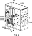
- FIG. 3 is an exploded schematic view of the hard disk assembly device with the hard disk and the case of FIG. 1 .
- the hard disk assembly device 100 is used for assembling the hard disk 400 into the case 500.
- the hard disk 400 can be assembled into the case 500 via the hard disk assembly device 100.
- the present disclosure adopts a quick disassembly and assembly structure between the hard disk 400 and the hard disk assembly device 100, thereby eliminating the use of the screws in the traditional assembly manner. Since any assembly, repair and replacement of the hard disk does not require any disassembly and assembly tool, the convenience of assembly, repair, and replacement of the hard disk can also be enhanced.
- FIG. 4 is an exploded schematic view of a flexible fixing frame of FIG. 2 .
- FIG. 5 is a front schematic view of the flexible fixing frame of FIG. 4 .
- FIG. 6 is a schematic view of a fixing bracket of FIG. 2 .
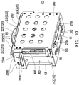
- FIG. 7 to FIG. 10 show an assembly process in which the hard disk is assembled to the fixing bracket via the flexible fixing frame.
- the hard disk 400 has a first side A1 and a second side A2 opposite to each other.
- the hard disk 400 has at least one first positioning portion 410 on the first side A1, and the hard disk 400 has at least one second positioning portion 420 on the second side A2.
- the hard disk assembly device 100 includes a flexible fixing frame 200 and a fixing bracket 300.
- the hard disk 400 is configured to be assembled to the flexible fixing frame 200;
- the flexible fixing frame 200 is configured to be assembled to the fixing bracket 300;
- the fixing bracket 300 is configured to be assembled to the case 500.
- the flexible fixing frame 200 has a third side B1 and a fourth side B2 opposite to each other.
- the flexible fixing frame 200 includes at least one third positioning portion 234 and at least one first guiding portion 212a on the third side B1.
- the flexible fixing frame 200 includes at least one fourth positioning portion 213a, a draw tape 220, and two fastening portions 224A and 224B on the fourth side B2.
- the two fastening portions 224A and 224B are connected with the two opposite ends of the draw tape 220.
- the number of the at least one first positioning portion 410, the at least one second positioning portion 420, the at least one third positioning portion 234, and the at least one fourth positioning portion 213a is respectively, for example, two, but not limited thereto.
- each of the above positioning portions may be described below in a single one form.
- the fixing bracket 300 has a bottom side C1 as well as a fifth side C2 and a sixth side C3 opposite to each other.
- the fixing bracket 300 has at least one second guiding portion 310 on the bottom side C1;
- the fixing bracket 300 has a limiting portion 320A and a guide portion 330A on the fifth side C2;
- the fixing bracket 300 has a limiting portion 320B and a guide portion 330B on the sixth side C3.
- the number of the at least one first guiding portion 212a and the at least one second guiding portion 310 is respectively, for example, two, but not limited thereto.
- each of the above guiding portions may be described below in a single one form.
- the two fastening portions 224A and 224B respectively abut against the two guide portions 330A and 330B to guide the flexible fixing frame 200 to slide to a position where it is correctly assembled to the fixing bracket 300.
- the first guiding portion 212a is inserted into the second guiding portion 310 to guide the flexible fixing frame 200 to a position where it is correctly assembled to the fixing bracket 300.
- the fixing bracket 300 When the flexible fixing frame 200 is assembled to the fixing bracket 300, the first guiding portion 212a is engaged with the second guiding portion 310, and the two fastening portions 224A and 224B are respectively correspondingly engaged with the two limiting portions 320A and 320B to allow the flexible fixing frame 200 to be fixed to the fixing bracket 300.
- the fixing bracket 300 may be a metal material, but is not limited thereto.
- the first positioning portion 410 and the second positioning portion 420 of the hard disk 400 are hole-like structures
- the third positioning portion 234 and the fourth positioning portion 213a of the flexible fixing frame 200 are columnar structures corresponding to the first positioning portion 410 and the second positioning portion 420 (or may be referred to as columnar structures corresponding to the hole-like structures).
- the third positioning portion 234 and the fourth positioning portion 213a of the flexible fixing frame 200 are respectively configured to pass through the first positioning portion 410 and the second positioning portion 420 of the hard disk 400 to limit the relative position between the hard disk 400 and the flexible fixing frame 200, but are not limited thereto.
- the first guiding portion 212a of the flexible fixing frame 200 is a columnar structure
- the second guiding portion 310 of the fixing bracket 300 is a hole-like structure corresponding to the first guiding portion 212a (or may be referred to as a hole-like structure corresponding to the columnar structure).
- the first guiding portion 212a of the flexible fixing frame 200 is configured to pass through the second guiding portion 310 of the fixing bracket 300 to limit the relative position between the flexible fixing frame 200 and the fixing bracket 300, but not limited thereto.
- the case 500 includes a plurality of first engaging portions 510
- the fixing bracket 300 includes a plurality of second engaging portions 340 corresponding to the plurality of first engaging portions 510.
- the second engaging portion 340 of the fixing bracket 300 is a hook-like structure
- the first engaging portion 510 of the case 500 is a hole-like structure corresponding to the second engaging portion 340 (or may be referred to as a hole-like structure corresponding to the hook-like structure).
- the second engaging portion 340 of the fixing bracket 300 is adapted to pass through the first engaging portion 510 of the case 500 and be hooked to the case to limit the relative position between the fixing bracket 300 and the case 500, but not limited thereto.
- the flexible fixing frame 200 includes a frame body 210.
- the third positioning portion 234 is coupled to the frame body 210.
- the first guiding portion 212a and the fourth positioning portion 213a are respectively connected with the frame body 210.
- the two opposite ends of the draw tape 220 are respectively connected with the frame body 210, and the frame body 210 is configured to accommodate the hard disk 400.
- the third positioning portion 234 is located between the first guiding portion 212a and the fourth positioning portion 213a, and the fourth positioning portion 213a is located between the third positioning portion 234 and the draw tape 220.
- the flexible fixing frame 200 is, for example, a plastic material, and the flexible fixing frame 200 made of the plastic material is configured to generate elastic deformation to fix the hard disk 400 or fix the flexible fixing frame 200 to the fixing bracket 300, but not limited thereto.
- the frame body 210, the first guiding portion 212a, the fourth positioning portion 213a, the draw tape 220, and the two fastening portions 224A and 224B may be integrally formed, but not limited thereto.
- the frame body 210 includes a bottom frame 211, a first side wall 212, and a second side wall 213.
- the first side wall 212 is connected with one side of the bottom frame 211 and corresponds to the first side A1 of the hard disk 400.
- the second side wall 213 is connected with the other side of the bottom frame 211 and corresponds to the second side A2 of the hard disk 400.
- the third positioning portion 234 is coupled to the first side wall 212.
- the first guiding portion 212a is connected with the first side wall 212.
- the fourth positioning portion 213a, the draw tape 220, and the two fastening portions 224A and 224B are connected with the second side wall 213.
- the flexible fixing frame 200 further includes a first gap T1 and a second gap T2.
- the first gap T1 is located between the first side wall 212 and the second side wall 213 and is located on one side of the bottom frame 211.
- the second gap T2 is located between the first side wall 212 and the second side wall 213 and is located on the other side of the bottom frame 211.
- the first gap T1 and the second gap T2 are configured to make the second side wall 213 easy to generate elastic deformation in a direction away from the first side wall 212.
- the width of the second gap T2 is greater than the width of the first gap T1 to facilitate a flexible flat cable (not shown) to pass through, thus allowing the hard disk 400 to be connected with an external electronic device (not shown), but not limited thereto.
- the bottom frame 211 includes a first connecting portion 211a, a second connecting portion 211b, and a third connecting portion 211c.
- the second connecting portion 211b is connected with the first connecting portion 211a
- the third connecting portion 211c is connected with the second connecting portion 211b.
- the second connecting portion 211b is located between the first connecting portion 211a and the third connecting portion 211c.
- the first side wall 212 is connected with one end of the first connecting portion 211a, the second connecting portion 211b, and the third connecting portion 211c
- the second side wall 213 is connected with the other end of the first connecting portion 211a, the second connecting portion 211b, and the third connecting portion 211c.
- the width of the flexible fixing frame 200 at the second connecting portion 211b is equal to the width of the third connecting portion 211c, and the width of the first connecting portion 211a is greater than the width of the second connecting portion 211b and the width of the third connecting portion 211c so as to enhance the overall strength of the flexible fixing frame 200. Accordingly, the fatigue resistance of the flexible fixing frame 200 can be increased, thereby increasing the service life of the flexible fixing frame 200.
- the first connecting portion 211a has a recess 211a1.
- the recess 211a1 of the first connecting portion 211a refers to a portion where the first connecting portion 211a is relatively thin in thickness. Since the width of the first connecting portion 211a is greater than the width of the second connecting portion 211b and the width of the third connecting portion 211c, the thickness of the first connecting portion 211a is relatively reduced at a certain portion, so that the second side wall 213 is easy to generate elastic deformation in a direction away from the first side wall 212.
- the recess 211a1 may be located at the middle section of the first connecting portion 211a, but not limited thereto.
- the bottom frame 211 has a first opening O1 between the first connecting portion 211a and the second connecting portion 211b, and the bottom frame 211 has a second opening 02 between the second connecting portion 211b and the third connecting portion 211c.
- the first opening O1 and the second opening 02 make the second side wall 213 easy to generate elastic deformation in a direction away from the first side wall 212 and help the hard disk 400 dissipate heat.
- the bottom frame 211 may further include a fourth connecting portion 211d, a fifth connecting portion 211e, a sixth connecting portion 211f, and a seventh connecting portion 211g.
- the two ends of the fourth connecting portion 211d are connected with one end of the first connecting portion 211a and one end of the second connecting portion 211b, and the two ends of the fifth connecting portion 211e are connected with the other end of the first connecting portion 211a and the other end of the second connecting portion 211b.
- the two ends of the sixth connecting portion 211f are connected with one end of the second connecting portion 211b and one end of the third connecting portion 211c, and the two ends of the seventh connecting portion 211g are connected with the other end of the second connecting portion 211b and the other end of the third connecting portion 211c.
- the first side wall 212 is connected with the fourth connecting portion 211d and the sixth connecting portion 211f, and the second side wall 213 is connected with the fifth connecting portion 211e and the seventh connecting portion 211g.
- the second connecting portion 211b is located between the fourth connecting portion 211d and the sixth connecting portion 211f, and the second connecting portion 211b is located between the fifth connecting portion 211e and the seventh connecting portion 211g.
- first connecting portion 211a, the second connecting portion 211b, the fourth connecting portion 211d, and the fifth connecting portion 211e can form the first opening O1
- the second connecting portion 211b, the third connecting portion 211c, the fifth connecting portion 211e, and the seventh connecting portion 211g can form the second opening 02, but not limited thereto.
- the flexible fixing frame 200 further includes at least one positioning member 230, and the flexible fixing frame 200 has at least one first fastening hole 212b and at least one second fastening hole 212c communicating with the at least one first fastening hole 212b at the first side wall 212 of the frame body 210.
- the number of the at least one positioning member 230, the at least one first fastening hole 212b, and the at least one second fastening hole 212c is respectively two.
- the two positioning members 230, the two first fastening holes 212b, and the two second fastening holes 212c are described below only in a single one form.
- the positioning member 230 includes a body 231, a penetrating portion 232, and a buffer portion 233.
- the body 231 is configured to pass through the first fastening hole 212b
- the penetrating portion 232 is connected with the body 231 and is configured to pass through one of the first fastening hole 212b and the second fastening hole 212c.
- the buffer portion 233 is connected with the penetrating portion 232, and the penetrating portion 232 is located between the body 231 and the buffer portion 233.
- the third positioning portion 234 is connected with the buffer portion 233, and the buffer portion 233 is located between the penetrating portion 232 and the third positioning portion 234.
- the buffer portion 233 is configured to abut against the hard disk 400 to reduce the vibration transmitted into the hard disk 400 by the case 500.
- the hole diameter of the first fastening hole 212b is greater than the hole diameter of the second fastening hole 212c; the outer diameter of the body 231 is equal to the hole diameter of the first fastening hole 212b; the outer diameter of the penetrating portion 232 is equal to the hole diameter of the second fastening hole 212c; the outer diameter of the buffer portion 233 is greater than both the hole diameter of the first fastening hole 212b and the hole diameter of the second fastening hole 212c.
- the outer diameter of the positioning member 230 at the body 231 is greater than the outer diameter of the positioning member 230 at the penetrating portion 232, and the outer diameter of the body 231 and the outer diameter of the buffer portion 233 are respectively greater than the hole diameter of the second fastening hole 212c. Accordingly, when the penetrating portion 232 moves into the second fastening hole 212c, the first side wall 212 is sandwiched by the body 231 and the buffer portion 233, so that the positioning member 230 can be fixed to the frame body 210.
- the draw tape 220 includes a tape body 221, a pulling portion 222, and two pressing portions 223, and is connected to the aforementioned two fastening portions 224A and 224B.
- the two ends of the tape body 221 are respectively connected with the frame body 210.
- the pulling portion 222 is connected with the tape body 221 and configured to make the tape body 221 generate elastic deformation in a direction away from the frame body 210.
- the two pressing portions 223 are connected with the tape body 221, and the pulling portion 222 is located between the two pressing portions 223.
- the two fastening portions 224A and 224B are connected with the two opposite ends of the tape body 221.
- the two pressing portions 223 are configured to move the two fastening portions 224A and 224B into the two limiting portions 320A and 320B.
- the two fastening portions 224A and 224B of the flexible fixing frame 200 are hook-like structures
- the two limiting portions 320A and 320B of the fixing bracket 300 are hole-like structures corresponding to the two fastening portions 224A and 224B (or may be referred to as hole-like structures corresponding to the hook-like structures).
- the two fastening portions 224A and 224B pass through and are engage with the two limiting portions 320A and 320B to limit the relative position between the flexible fixing frame 200 and the fixing bracket 300, but not limited thereto.
- the flexible fixing frame 200 has a third gap T3 between the draw tape 220 and the frame body 210.
- the third gap T3 is configured to make the draw tape 220 easy to generate elastic deformation in a direction away from the two limiting portions 320A and 320B further to move the two fastening portions 224A and 224B out of the two limiting portions 320A and 320B.
- the draw tape 220 may further include two reinforcing portions 225A and 225B connected with the two ends of the tape body 221 to increase the connection strength between the draw tape 220 and the frame body 210, thereby increasing the service life of the draw tape 220.
- the fixing bracket 300 may further have a retaining wall 350, a notch 360, and a locking hole respectively located on two sides of the bracket 300.
- the retaining wall 350 is located on the fifth side C2 of the fixing bracket 300
- the notch 360 is located on the sixth side C3 of the fixing bracket 300.
- the locking hole and the second engaging portion 340 are located on the same side of the fixing bracket 300.
- the retaining wall 350 is configured to cover the flexible fixing frame 200; the notch 360 is configured to provide a space for a flexible flat cable (not shown) to pass through; the locking hole is available for a locking member (not shown) to pass through thus to allow the fixing bracket 300 to be fixed to the case 500.
- a hard disk 400 is provided; the first side A1 of the hard disk 400 is oriented toward the inner wall surface of the first side wall 212 of the flexible fixing frame 200 on the third side B1; the first positioning portion 410 of the hard disk 400 on the first side A1 is aligned with the third positioning portion 234 of the flexible fixing frame 200 on the inner wall surface of the first side wall 212; the third positioning portion 234 of the flexible fixing frame 200 on the inner wall surface of the first side wall 212 passes through the first positioning portion 410 of the hard disk 400 on the first side A1 thus to allow the first side A1 of the hard disk 400 to be fixed to the third side B1 of the flexible fixing frame 200.
- a force is applied to make the second side wall 213 of the flexible fixing frame 200 on the fourth side B2 generate elastic deformation in a direction away from the first side wall 212 of the flexible fixing frame 200 on the third side B1 such that the accommodating space of the flexible fixing frame 200 inside the frame body 210 is increased;
- the second side A2 of the hard disk 400 is moved into the accommodating space inside the frame body 210 of the flexible fixing frame 200 such that the hard disk 400 abuts against the bottom frame 211 of the flexible fixing frame 200;
- the force applied to the second side wall 213 of the flexible fixing frame 200 on the fourth side B2 is removed to make the fourth positioning portion 213a of the flexible fixing frame 200 on the inner wall surface of the fourth side B2 pass through the second positioning portion 420 of the hard disk 400 on the second side A2, such that the second side A2 of the hard disk 400 is fixed
- the third positioning portion 234 passes through the first positioning portion 410 (for example, a screw hole originally existing in the hard disk 400), and the fourth positioning portion 213a passes through the second positioning portion 420 (for example, a screw hole originally existing in the hard disk 400), such that the hard disk 400 can be firmly fixed to the flexible fixing frame 200, as shown in FIG. 9 .
- the third side B3 of the flexible fixing frame 200 is oriented toward the inner wall surface of the bottom side C1 of the fixing bracket 300; the first guiding portion 212a of the flexible fixing frame 200 on the third side B1 is inserted into the second guiding portion 310 of the fixing bracket 300 on the bottom side C1, and the two fastening portions 224A and 224B of the flexible fixing frame 200 abut against the guide portions 330A and 330B of the fixing bracket 300 on the fifth side C2 and the sixth side C3 to guide the flexible fixing frame 200 to a position where it is correctly assembled to the fixing bracket 300; a down force is applied to make the draw tape 220 of the flexible fixing frame 200 generate elastic deformation to allow the two fastening portions 224A and 224B of the flexible fixing frame 200 to move in a direction away from the two guide portions 330A and 330B (or may be referred to the direction
- the two first guiding portions 212a of the flexible fixing frame 200 on the third side B1 are engaged with the two second guiding portions 310 of the fixing bracket 300 on the bottom side C1, and the flexible fixing frame 200 can be firmly fixed to the fixing bracket 300 by the engaging force between the two fastening portions 224A and 224B and the two limiting portions 320A and 320B, as shown in FIG. 2 .
- the steps of assembling the fixing bracket 300 to the case 500 are described: the second engaging portion 340 of the fixing bracket 300 is aligned with the first engaging portion 510 of the case 500; the fixing bracket 300 is moved toward the case 500 to allow the second engaging portion 340 of the fixing bracket 300 to move into the first engaging portion 510 of the case 500; a down force is applied to make the second engaging portion 340 of the fixing bracket 300 engaged with the first engaging portion 510 of the case 500 to allow the fixing bracket 300 to be fixed to the case 500.
- the hard disk 400 can be firmly fixed to the case 500 via the flexible fixing frame 200 and the fixing bracket 300, as shown in FIG. 1 .
- the hard disk 400 can be quickly assembled into the case 500 via the hard disk assembly device 100, and therefore the hard disk 400 can be quickly assembled on the production line, thereby reducing the waste of assembly time, increasing the productivity of the product, and reducing the assembly cost.
- the flexible fixing frame 200 made of the plastic material can absorb external vibration (for example, vibration from the case 500), and can protect the hard disk 400 from external vibration, thereby increasing the service life of the hard disk 400.
- the locking member (not shown) can be further locked into the locking hole of the fixing bracket 300, such that the fixing bracket 300 is further firmly fixed to the case 500.
- a pulling force is applied to the pulling portion 222 of the flexible fixing frame 200 at the draw tape 220 to allow the two fastening portions 224A and 224B of the flexible fixing frame 200 to move in a direction away from the two limiting portions 320A and 320B of the fixing bracket 300, thereby releasing the bond between the flexible fixing frame 200 and the fixing bracket 300; the pulling force is continuously applied to move the flexible fixing frame 200 out of the fixing bracket 300.
- the flexible fixing frame 200 can be directly removed from the fixing bracket 300 without any tools, and the fixing bracket 300 can still be fixed to the case 500.
- the hard disk 400 can be directly disassembled from the flexible fixing frame 200 without using any tools by using the reverse steps of assembling the hard disk 400 to the flexible fixing frame 200. The relevant steps are not repeated here.
- the disassembly of the hard disk 400 is fast and convenient, thereby eliminating the use of the screws in the traditional assembly manner. Since any assembly, repair, and replacement of the hard disk does not require any disassembly and assembly tool, the convenience of assembly, repair, and replacement of the hard disk can also be enhanced.
Landscapes
- Engineering & Computer Science (AREA)
- Theoretical Computer Science (AREA)
- Computer Hardware Design (AREA)
- Power Engineering (AREA)
- Human Computer Interaction (AREA)
- Physics & Mathematics (AREA)
- General Engineering & Computer Science (AREA)
- General Physics & Mathematics (AREA)
- Connection Of Plates (AREA)
- Mounting Components In General For Electric Apparatus (AREA)
- Electrophotography Configuration And Component (AREA)
- Casings For Electric Apparatus (AREA)
Claims (17)
- Festplattenmontagevorrichtung (100) zum Montieren einer Festplatte (400), aufweisend wenigstens einen ersten Positionierungsabschnitt (410) und wenigstens einen zweiten Positionierungsabschnitt (420) an jeweils zwei gegenüberliegenden Seiten davon in ein Gehäuse (500), wobei die Festplattenmontagevorrichtung (100) umfasst:einen flexiblen Befestigungsrahmen (200), der konfiguriert ist, darin die Festplatte (400) aufzunehmen; undeinen Befestigungshalter (300), der konfiguriert ist, in dem Gehäuse (500) befestigt zu sein und darin den flexiblen Befestigungsrahmen (200) aufzunehmen, wobei der flexible Befestigungsrahmen (200) umfasst:
einen Bodenrahmen (211), aufweisend gegenüberliegende erste und zweite Seiten, und gegenüberliegende dritte und vierte Seiten zwischen den ersten und zweiten Seiten;eine erste Seitenwand (212), die mit der ersten Seite des Bodenrahmens (211) verbunden ist und wenigstens ein drittes Positionierungselement (230) und wenigstens einen ersten Führungsabschnitt (212a) einschließt;eine zweite Seitenwand (213), die einen ersten Seitenwandabschnitt (214), verbunden mit der zweiten Seite des Bodenrahmens (211) die der ersten Seite gegenüberliegt, und zweite und dritte Seitenwandabschnitte (215, 216) einschließt, die jeweils an der dritten Seite und der vierten Seite des Bodenrahmens verbunden sind;ein Zugband (220), das sich entlang der Außenwandfläche der zweiten Seitenwand (213) erstreckt, wobei jeweils zwei Enden des Zugbandes (220) jeweils mit dem zweiten Seitenwandabschnitt (215) und dem dritten Seitenwandabschnitt (216) der zweiten Seitenwand (213) verbunden sind, über einen ersten Befestigungsabschnitt (224A) und einen zweiten Befestigungsabschnitt (224B); und wenigstens ein vierter Positionierungsabschnitt (213a), verbunden mit dem ersten Seitenwandabschnitt (214) der zweiten Seitenwand (213); wobei der Bodenrahmen und die ersten und zweiten Seitenwände (212, 213) einen Rahmenkörper (210) definieren, der konfiguriert ist, die Festplatte (400) aufzunehmen; und wobei das wenigstens eine dritte Positionierungselement (230) wenigstens einen Positionierungsabschnitt (234) enthält, der konfiguriert ist mit dem wenigstens einen ersten Positionierungsabschnitt (410) der Festplatte (400) einzugreifen, und der wenigstens eine vierte Positionierungsabschnitt (213a) konfiguriert ist, mit dem wenigstens einen zweiten Positionierungsabschnitt (420) der Festplatte (400) einzugreifen, wenn die Festplatte (400) an dem flexiblen Befestigungsrahmen (200) montiert ist, um der Festplatte (400) zu ermöglichen, in dem flexiblen Befestigungsrahmen (200) befestigt zu werden; und der Befestigungshalter (300) umfasst:
eine Bodenseite (C1) und zwei gegenüberliegende Seiten (C2, C3), wobei die Bodenseite (C1) des Befestigungshalters (300) wenigstens einen zweiten Führungsabschnitt (310) enthält, der konfiguriert ist mit dem wenigstens einen Führungsabschnitt (212a) des flexiblen Befestigungsrahmens (200) einzugreifen, wenn der flexible Befestigungsrahmen (200) an dem Befestigungshalter (300) montiert ist, und wobei die zwei Seiten (C2, C3) des Befestigungshalters (300) jeweils einen ersten Begrenzungsabschnitt (320A) und einen zweiten Begrenzungsabschnitt (320B) enthalten, konfiguriert, um jeweils mit dem entsprechenden einen der zwei Befestigungsabschnitte (224A, 224B) des flexiblen Befestigungsrahmens (200) einzugreifen, wenn der flexible Befestigungsrahmen (200) an dem Befestigungshalter (300) montiert ist. - Festplattenmontagevorrichtung (100) gemäß Anspruch 1, wobei der flexible Befestigungsrahmen (200) aus einem Kunststoffmaterial ist und der flexible Befestigungsrahmen (200) in der Lage ist, eine elastische Verformung zu erzeugen.
- Festplattenmontagevorrichtung (100) gemäß Anspruch 1, wobei der Befestigungshalter (300) aus einem Metallmaterial ist.
- Festplattenmontagevorrichtung (100) gemäß Anspruch 1, wobei der wenigstens eine dritte Positionierungsabschnitt (234) und der wenigstens eine vierte Positionierungsabschnitt (213a) säulenartige Strukturen sind, die konfiguriert sind, jeweils mit den entsprechenden lochartigen Strukturen des wenigstens einen ersten Positionierungsabschnitts (410) und des wenigstens einen zweiten Positionierungsabschnitts (420) der Festplatte (400) einzugreifen, um die relative Position zwischen der Festplatte (400) und dem flexiblen Befestigungsrahmen (200) zu begrenzen.
- Festplattenmontagevorrichtung (100) gemäß Anspruch 1, wobei der wenigstens eine erste Führungsabschnitt (212a) eine säulenartige Struktur ist, der wenigstens eine zweite Führungsabschnitt (310) eine lochartige Struktur ist, die dem wenigstens einen ersten Führungsabschnitt (212a) entspricht, und der wenigstens eine erste Führungsabschnitt (212a) mit dem wenigstens einen zweiten Führungsabschnitt (310) einzugreifen, um die relative Position zwischen dem flexiblen Befestigungsrahmen (200) und dem Befestigungshalter (300) zu begrenzen.
- Festplattenmontagevorrichtung (100) gemäß Anspruch 1, wobei die beiden Befestigungsabschnitte (224A, 224B) hakenartige Strukturen sind, die beiden Begrenzungsabschnitte (320A, 320B) lochartige Strukturen sind, die den beiden Befestigungsabschnitten (224A, 224B) entsprechen, und die beiden Befestigungsabschnitte (224A, 224B) konfiguriert sind mit den beiden Begrenzungsabschnitten (320A, 320B) einzugreifen, um die relative Position zwischen dem flexiblen Befestigungsrahmen (200) und dem Befestigungshalter (300) zu begrenzen.
- Festplattenmontagevorrichtung (100) gemäß Anspruch 1, wobei der Rahmenkörper (210), der wenigstens eine erste Führungsabschnitt (212a), der wenigstens eine vierte Positionierungsabschnitt (213a), das Zugband (220) und die zwei Befestigungsabschnitte (224A, 224B) einstückig ausgebildet sind.
- Festplattenmontagevorrichtung (100) gemäß Anspruch 1, wobei der wenigstens eine dritte Positionierungsabschnitt (234) mit der einen Seitenwand (212) der beiden gegenüberliegenden Seitenwände (212, 213) gekoppelt ist, und der wenigstens eine erste Führungsabschnitt (212a) mit der einen Seitenwand (212) der beiden gegenüberliegenden Seitenwände (212, 213) verbunden ist, wobei der wenigstens eine vierte Positionierungsabschnitt (213a), das Zugband (220) und die beiden Befestigungsabschnitte (224A, 224B) mit der anderen Seitenwand (213) der beiden gegenüberliegenden Seitenwände (212, 213) verbunden sind.
- Festplattenmontagevorrichtung (100) gemäß Anspruch 8, wobei der flexible Befestigungsrahmen (200) ferner einen ersten Spalt (T1) und einen zweiten Spalt (T2) enthält; wobei der erste Spalt (T1) sich auf der dritten Seite des Bodenrahmens (211) zwischen der ersten Seitenwand (212) und dem zweiten Seitenwandabschnitt (215) der zweiten Seitenwand (213) befindet, der zweite Spalt (T2) sich auf der vierten Seite des Bodenrahmens (211) zwischen der ersten Seitenwand 212 und dem dritten Seitenwandabschnitt (216) der zweiten Seitenwand (213) befindet, und der erste Spalt (T1) und der zweite Spalt (T2) sind konfiguriert, die zweite Seitenwand (213) dazu zu bringen, um leicht eine elastische Verformung in einer Richtung weg von der ersten Seitenwand (212) zu erzeugen.
- Festplattenmontagevorrichtung (100) gemäß Anspruch 8, wobei der Bodenrahmen (211) umfasst:eine erste Öffnung (O1), die zwischen dem ersten Verbindungsabschnitt (211a) und dem zweiten Verbindungsabschnitt (211b) verbunden ist; undeine zweite Öffnung (02), die zwischen dem zweiten Verbindungsabschnitt (211b) und einem dritten Verbindungsabschnitt (211c) verbunden ist, wobei die erste Seitenwand (212) mit einen Ende des ersten Verbindungsabschnitts (211a), dem zweiten Verbindungsabschnitt (211b) und dem dritten Verbindungsabschnitt (211c) verbunden ist, und wobei die erste Seitenwand (212) mit dem anderen Ende des ersten Verbindungsabschnitts (211a), des zweiten Verbindungsabschnitts (211b) und des dritten Verbindungsabschnitts (211c) verbunden ist.
- Festplattenmontagevorrichtung (100) gemäß Anspruch 10, wobei der Bodenrahmen (211) ferner umfasst:einen vierten Verbindungsabschnitt (211d), wobei zwei Enden des vierten Verbindungsabschnitts (211d) mit einem Ende des ersten Verbindungsabschnitts (211a) und einem Ende des zweiten Verbindungsabschnitts (211b) verbunden sind;einen fünften Verbindungsabschnitt (211e), wobei zwei Enden des fünften Verbindungsabschnitts (211e) mit dem anderen Ende des ersten Verbindungsabschnitts (211a) und dem anderen Ende des zweiten Verbindungsabschnitts (211b) verbunden sind;einen sechsten Verbindungsabschnitt (211f), wobei zwei Enden des sechsten Verbindungsabschnitts (211f) mit einem Ende des zweiten Verbindungsabschnitts (211b) und einem Ende des dritten Verbindungsabschnitts (211c) verbunden sind, wobei der zweite Verbindungsabschnitt (211b) zwischen dem vierten Verbindungsabschnitt (211d) und dem sechsten Verbindungsabschnitt (211f) angeordnet ist; undeinen siebten Verbindungsabschnitt (211g), wobei zwei Enden des siebten Verbindungsabschnitts (211g) mit dem anderen Ende des zweiten Verbindungsabschnitts (211b) und dem anderen Ende des dritten Verbindungsabschnitts (211c) verbunden sind, wobei der zweite Verbindungsabschnitt (211b) zwischen dem fünften Verbindungsabschnitt (211e) und dem siebten Verbindungsabschnitt (211g) angeordnet ist, die erste Seitenwand (212) mit dem vierten Verbindungsabschnitt (211d) und dem sechsten Verbindungsabschnitt (211f) verbunden ist, und die zweite Seitenwand (213) mit dem ersten Verbindungsabschnitt (211a), dem fünften Verbindungsabschnitt (211e), dem siebten Verbindungsabschnitt (211g) und dem dritten Verbindungsabschnitt (211c) verbunden ist.
- Festplattenmontagevorrichtung (100) gemäß Anspruch 10, wobei die Breite des ersten Verbindungsabschnitts (211a) größer ist als die Breite des zweiten Verbindungsabschnitts (211b) und die Breite des dritten Verbindungsabschnitts (211c), um die Gesamtfestigkeit des flexiblen Befestigungsrahmens (200) zu erhöhen.
- Festplattenmontagevorrichtung (100) gemäß Anspruch 10, wobei der erste Verbindungsabschnitt (211a) eine Aussparung (211a1) aufweist, und die Aussparung (211a1) konfiguriert ist, die zweite Seitenwand (213) dazu zu bringen, um leicht elastische Verformung in einer Richtung weg von der ersten Seitenwand (212) zu erzeugen.
- Festplattenmontagevorrichtung (100) gemäß Anspruch 1, wobei die erste Seitenwand (212) ferner umfasst:wenigstens ein erstes Befestigungsloch (212b);wenigstens ein zweites Befestigungsloch (212c), das mit dem wenigstens einen ersten Befestigungsloch (212b) in Verbindung steht; und das dritte Positionierungselement (230) umfasst:einen Körper (231), der konfiguriert ist, dass er durch das wenigstens eine erste Befestigungsloch (212b) hindurchgeht;einen Durchdringungsabschnitt (232), der mit dem Körper (231) verbunden ist und konfiguriert ist, dass er durch das wenigstens eine erste Befestigungsloch (212b) und das wenigstens eine zweite Befestigungsloch (212c) hindurchgeht, wobei, so dass sich wenn der Durchdringungsabschnitt (232) in das zweite Befestigungsloch (212c) hineinbewegt, das Positionierungselement (230) an die erste Seitenwand (212) befestigt wird; undeinen Pufferabschnitt (233), der mit dem Durchdringungsabschnitt (232) verbunden ist, wobei der Durchdringungsabschnitt (232) zwischen dem Körper (231) und dem Pufferabschnitt (233) angeordnet ist, wobei der wenigstens eine dritte Positionierungsabschnitt (234) mit dem Pufferabschnitt (233) verbunden ist, der Pufferabschnitt (233) zwischen dem Durchdringungsabschnitt (232) und dem wenigstens einen dritten Positionierungsabschnitt (234) angeordnet ist, und der Pufferabschnitt (233) konfiguriert ist, dass er an der Festplatte (400) anliegt, um die durch das Gehäuse (500) in die Festplatte (400) übertragene Vibration zu reduzieren, wobei der Lochdurchmesser des wenigstens einen ersten Befestigungslochs (212b) größer ist als der Lochdurchmesser des wenigstens einen zweiten Befestigungslochs (212c), der Außendurchmesser des Körpers (231) gleich dem Lochdurchmesser des wenigstens einen ersten Befestigungslochs (212b) ist, der Außendurchmesser des Durchdringungsabschnitt (232) gleich dem Lochdurchmesser des wenigstens einen zweiten Befestigungslochs (212c) ist, und der Außendurchmesser des Pufferabschnitts (233) größer ist als der Lochdurchmesser des wenigstens einen ersten Befestigungslochs (212b) und der Lochdurchmesser des wenigstens einen zweiten Befestigungslochs (212c).
- Festplattenmontagevorrichtung (100) gemäß Anspruch 1, wobei das Zugband (220) umfasst:einen Bandkörper (221), wobei zwei Enden des Bandkörpers (221) jeweils mit dem zweiten Seitenwandabschnitt (215) und dem dritten Seitenwandabschnitt (216) der zweiten Seitenwand (213) verbunden sind;einen Zugabschnitt (222), der mit dem Bandkörper (221) verbunden und konfiguriert ist, dass er den Bandkörper (221) dazu bringt, eine elastische Verformung in einer Richtung weg von dem Rahmenkörper (210) zu erzeugen; undzwei Druckabschnitte (223), die mit dem Bandkörper (221) verbunden sind, wobei der Zugabschnitt (222) zwischen den beiden Druckabschnitten (223) angeordnet ist und die zwei Druckabschnitte (223) konfiguriert sind, dass sie den zwei Befestigungsabschnitten (224A, 224B) helfen, sich in die zwei Begrenzungsabschnitte (320A, 320B) zu bewegen, wenn eine drückende Kraft auf die zwei Druckabschnitte (223) ausgeübt wird.
- Festplattenmontagevorrichtung (100) gemäß Anspruch 15, wobei das Zugband (220) ferner umfasst:
zwei Verstärkungsabschnitte (225A, 225B), die mit den beiden Enden des Bandkörpers (221) verbunden sind, um die Verbindungsfestigkeit zwischen dem Zugband (220) und dem Rahmenkörper (210) zu erhöhen. - Festplattenmontagevorrichtung (100) gemäß Anspruch 15, wobei der flexible Befestigungsrahmen (200) einen dritten Spalt (T3) aufweist, der zwischen dem Zugband (220) und der zweiten Seitenwand (213) angeordnet ist, wobei der dritte Spalt (T3) konfiguriert ist, das Zugband (220) dazu zu bringen, leicht eine elastische Verformung in einer Richtung weg von den zwei Begrenzungsabschnitten (320A, 320B) zu erzeugen, und um es den beiden Befestigungsabschnitten (224A, 224B) zu ermöglichen, sich aus den beiden Begrenzungsabschnitten (320A, 320B) herauszubewegen.
Applications Claiming Priority (1)
| Application Number | Priority Date | Filing Date | Title |
|---|---|---|---|
| CN201810737838.7A CN110687972B (zh) | 2018-07-06 | 2018-07-06 | 硬盘组装装置 |
Publications (2)
| Publication Number | Publication Date |
|---|---|
| EP3591501A1 EP3591501A1 (de) | 2020-01-08 |
| EP3591501B1 true EP3591501B1 (de) | 2021-10-27 |
Family
ID=67137791
Family Applications (1)
| Application Number | Title | Priority Date | Filing Date |
|---|---|---|---|
| EP19183533.9A Active EP3591501B1 (de) | 2018-07-06 | 2019-07-01 | Festplattenmontagevorrichtung |
Country Status (6)
| Country | Link |
|---|---|
| US (1) | US10535376B1 (de) |
| EP (1) | EP3591501B1 (de) |
| JP (1) | JP6802326B2 (de) |
| KR (1) | KR102128429B1 (de) |
| CN (1) | CN110687972B (de) |
| TW (1) | TWI698861B (de) |
Families Citing this family (2)
| Publication number | Priority date | Publication date | Assignee | Title |
|---|---|---|---|---|
| CN112181072A (zh) * | 2020-09-17 | 2021-01-05 | 苏州浪潮智能科技有限公司 | 一种免硬盘托架的硬盘框架及服务器 |
| US11688432B2 (en) | 2020-11-16 | 2023-06-27 | International Business Machines Corporation | Disk drive and carrier assembly |
Family Cites Families (20)
| Publication number | Priority date | Publication date | Assignee | Title |
|---|---|---|---|---|
| KR100528459B1 (ko) * | 1998-07-23 | 2005-11-15 | 삼성전자주식회사 | 보조 기기 장착 구조 |
| KR20000011201U (ko) * | 1998-11-28 | 2000-06-26 | 이명옥 | 트랙터용 배토기 |
| JP2002124070A (ja) * | 2000-10-12 | 2002-04-26 | Funai Electric Co Ltd | ディスクドライブ機器の取付構造 |
| KR100422249B1 (ko) * | 2001-08-30 | 2004-03-11 | 삼성전자주식회사 | 컴퓨터용 hdd지지프레임 |
| TWI237542B (en) * | 2004-07-16 | 2005-08-01 | First Int Computer Inc | Electronic apparatus installing base |
| TWM278998U (en) * | 2005-02-02 | 2005-10-21 | Sercomm Corp | External electronic data storing device |
| CN200983256Y (zh) * | 2006-10-11 | 2007-11-28 | 鸿富锦精密工业(深圳)有限公司 | 数据存储器固定装置 |
| CN101315574A (zh) * | 2007-06-01 | 2008-12-03 | 鸿富锦精密工业(深圳)有限公司 | 数据存储器固定装置 |
| JP4462310B2 (ja) * | 2007-09-10 | 2010-05-12 | アイシン・エィ・ダブリュ株式会社 | ディスク装置 |
| TWM370022U (en) * | 2009-07-24 | 2009-12-01 | Wistron Corp | Slide rail structure and hard drive device having the same |
| US8411432B1 (en) * | 2009-12-02 | 2013-04-02 | Dell Products, Lp | System, apparatus and method for tiered shock solution |
| TWI429379B (zh) * | 2011-11-21 | 2014-03-01 | Wistron Corp | 電子裝置托架、電子裝置抽換組件及電腦機殼 |
| TWI519228B (zh) * | 2012-05-25 | 2016-01-21 | 樺漢科技股份有限公司 | 硬碟機固定裝置 |
| CN103853272B (zh) * | 2012-11-30 | 2017-08-29 | 华为终端有限公司 | 组合硬盘托架 |
| TWI584276B (zh) * | 2013-09-18 | 2017-05-21 | 樺漢科技股份有限公司 | 接地件及設有該接地件的硬碟機固定裝置 |
| JP6131811B2 (ja) * | 2013-10-01 | 2017-05-24 | 富士通株式会社 | 情報処理装置 |
| TWM479492U (zh) * | 2013-12-18 | 2014-06-01 | Echostreams Innovative Solutions Llc | 伺服器機箱 |
| CN204515638U (zh) | 2015-03-24 | 2015-07-29 | 重庆工商职业学院 | 拆分式计算机硬盘盒 |
| JP6466373B2 (ja) * | 2016-07-29 | 2019-02-06 | 株式会社ソニー・インタラクティブエンタテインメント | 電子機器及びハードディスク装置のホルダー |
| TWM554693U (zh) * | 2017-09-08 | 2018-01-21 | Urack Enterprise Co Ltd | 電腦儲存裝置之快拆組 |
-
2018
- 2018-07-06 CN CN201810737838.7A patent/CN110687972B/zh active Active
-
2019
- 2019-03-28 TW TW108110936A patent/TWI698861B/zh active
- 2019-05-21 US US16/418,732 patent/US10535376B1/en active Active
- 2019-06-14 JP JP2019111323A patent/JP6802326B2/ja active Active
- 2019-06-26 KR KR1020190076300A patent/KR102128429B1/ko active Active
- 2019-07-01 EP EP19183533.9A patent/EP3591501B1/de active Active
Also Published As
| Publication number | Publication date |
|---|---|
| JP2020009525A (ja) | 2020-01-16 |
| US10535376B1 (en) | 2020-01-14 |
| KR20200005446A (ko) | 2020-01-15 |
| EP3591501A1 (de) | 2020-01-08 |
| CN110687972A (zh) | 2020-01-14 |
| TWI698861B (zh) | 2020-07-11 |
| JP6802326B2 (ja) | 2020-12-16 |
| KR102128429B1 (ko) | 2020-07-01 |
| TW202006710A (zh) | 2020-02-01 |
| US20200013433A1 (en) | 2020-01-09 |
| CN110687972B (zh) | 2023-11-21 |
Similar Documents
| Publication | Publication Date | Title |
|---|---|---|
| US9230606B2 (en) | Mounting apparatus assembly | |
| US9374930B2 (en) | Fan holding structure, heat-dissipating module with the fan holding structure and electronic device having the same | |
| CN101719005B (zh) | 滑轨结构 | |
| TW201349988A (zh) | 硬碟機固定裝置 | |
| US20130092807A1 (en) | Mounting apparatus for storage device | |
| US7983000B2 (en) | Removable disk drive mounting device including a first holder pivotally connected to second holders which in turn are detachably connected to a handle | |
| EP3591501A1 (de) | Festplattenmontagevorrichtung | |
| US20140139997A1 (en) | Installation structure of data storage device and data storage system using the same | |
| US20130059188A1 (en) | Battery mounting device | |
| US20080090511A1 (en) | Mounting apparatus for fan | |
| US9658658B2 (en) | Data storage device mounting structure | |
| US7874627B2 (en) | Assembly for connecting plates | |
| US8223491B2 (en) | Fastener for securing computer storage device | |
| CN104679171B (zh) | 硬盘组装结构 | |
| TWI461141B (zh) | 卡合模組及應用其的可攜式電子裝置 | |
| US8570733B2 (en) | Fastening device for data storage device | |
| US20140319312A1 (en) | Mounting device for hard disk drive | |
| CN207051801U (zh) | 硬盘支架 | |
| CN117590909A (zh) | 机箱 | |
| CN110147144A (zh) | 机壳以及包含所述机壳的主机 | |
| CN220301939U (zh) | 一种执手与传动轴的快装连接结构及相关结构 | |
| CN112449522A (zh) | 固定架 | |
| US20120008273A1 (en) | Disk drive mounting apparatus and disk drive assembly | |
| CN201007813Y (zh) | 扣具结构 | |
| EP4644038A1 (de) | Schraubenzuführvorrichtung |
Legal Events
| Date | Code | Title | Description |
|---|---|---|---|
| PUAI | Public reference made under article 153(3) epc to a published international application that has entered the european phase |
Free format text: ORIGINAL CODE: 0009012 |
|
| STAA | Information on the status of an ep patent application or granted ep patent |
Free format text: STATUS: THE APPLICATION HAS BEEN PUBLISHED |
|
| AK | Designated contracting states |
Kind code of ref document: A1 Designated state(s): AL AT BE BG CH CY CZ DE DK EE ES FI FR GB GR HR HU IE IS IT LI LT LU LV MC MK MT NL NO PL PT RO RS SE SI SK SM TR |
|
| AX | Request for extension of the european patent |
Extension state: BA ME |
|
| STAA | Information on the status of an ep patent application or granted ep patent |
Free format text: STATUS: REQUEST FOR EXAMINATION WAS MADE |
|
| 17P | Request for examination filed |
Effective date: 20200624 |
|
| RBV | Designated contracting states (corrected) |
Designated state(s): AL AT BE BG CH CY CZ DE DK EE ES FI FR GB GR HR HU IE IS IT LI LT LU LV MC MK MT NL NO PL PT RO RS SE SI SK SM TR |
|
| STAA | Information on the status of an ep patent application or granted ep patent |
Free format text: STATUS: EXAMINATION IS IN PROGRESS |
|
| 17Q | First examination report despatched |
Effective date: 20210324 |
|
| GRAP | Despatch of communication of intention to grant a patent |
Free format text: ORIGINAL CODE: EPIDOSNIGR1 |
|
| STAA | Information on the status of an ep patent application or granted ep patent |
Free format text: STATUS: GRANT OF PATENT IS INTENDED |
|
| INTG | Intention to grant announced |
Effective date: 20210528 |
|
| GRAS | Grant fee paid |
Free format text: ORIGINAL CODE: EPIDOSNIGR3 |
|
| GRAA | (expected) grant |
Free format text: ORIGINAL CODE: 0009210 |
|
| STAA | Information on the status of an ep patent application or granted ep patent |
Free format text: STATUS: THE PATENT HAS BEEN GRANTED |
|
| AK | Designated contracting states |
Kind code of ref document: B1 Designated state(s): AL AT BE BG CH CY CZ DE DK EE ES FI FR GB GR HR HU IE IS IT LI LT LU LV MC MK MT NL NO PL PT RO RS SE SI SK SM TR |
|
| REG | Reference to a national code |
Ref country code: GB Ref legal event code: FG4D |
|
| REG | Reference to a national code |
Ref country code: CH Ref legal event code: EP |
|
| REG | Reference to a national code |
Ref country code: AT Ref legal event code: REF Ref document number: 1442360 Country of ref document: AT Kind code of ref document: T Effective date: 20211115 |
|
| REG | Reference to a national code |
Ref country code: DE Ref legal event code: R096 Ref document number: 602019008628 Country of ref document: DE |
|
| REG | Reference to a national code |
Ref country code: IE Ref legal event code: FG4D |
|
| REG | Reference to a national code |
Ref country code: LT Ref legal event code: MG9D |
|
| REG | Reference to a national code |
Ref country code: NL Ref legal event code: MP Effective date: 20211027 |
|
| REG | Reference to a national code |
Ref country code: AT Ref legal event code: MK05 Ref document number: 1442360 Country of ref document: AT Kind code of ref document: T Effective date: 20211027 |
|
| PG25 | Lapsed in a contracting state [announced via postgrant information from national office to epo] |
Ref country code: RS Free format text: LAPSE BECAUSE OF FAILURE TO SUBMIT A TRANSLATION OF THE DESCRIPTION OR TO PAY THE FEE WITHIN THE PRESCRIBED TIME-LIMIT Effective date: 20211027 Ref country code: LT Free format text: LAPSE BECAUSE OF FAILURE TO SUBMIT A TRANSLATION OF THE DESCRIPTION OR TO PAY THE FEE WITHIN THE PRESCRIBED TIME-LIMIT Effective date: 20211027 Ref country code: FI Free format text: LAPSE BECAUSE OF FAILURE TO SUBMIT A TRANSLATION OF THE DESCRIPTION OR TO PAY THE FEE WITHIN THE PRESCRIBED TIME-LIMIT Effective date: 20211027 Ref country code: BG Free format text: LAPSE BECAUSE OF FAILURE TO SUBMIT A TRANSLATION OF THE DESCRIPTION OR TO PAY THE FEE WITHIN THE PRESCRIBED TIME-LIMIT Effective date: 20220127 Ref country code: AT Free format text: LAPSE BECAUSE OF FAILURE TO SUBMIT A TRANSLATION OF THE DESCRIPTION OR TO PAY THE FEE WITHIN THE PRESCRIBED TIME-LIMIT Effective date: 20211027 |
|
| PG25 | Lapsed in a contracting state [announced via postgrant information from national office to epo] |
Ref country code: IS Free format text: LAPSE BECAUSE OF FAILURE TO SUBMIT A TRANSLATION OF THE DESCRIPTION OR TO PAY THE FEE WITHIN THE PRESCRIBED TIME-LIMIT Effective date: 20220227 Ref country code: SE Free format text: LAPSE BECAUSE OF FAILURE TO SUBMIT A TRANSLATION OF THE DESCRIPTION OR TO PAY THE FEE WITHIN THE PRESCRIBED TIME-LIMIT Effective date: 20211027 Ref country code: PT Free format text: LAPSE BECAUSE OF FAILURE TO SUBMIT A TRANSLATION OF THE DESCRIPTION OR TO PAY THE FEE WITHIN THE PRESCRIBED TIME-LIMIT Effective date: 20220228 Ref country code: PL Free format text: LAPSE BECAUSE OF FAILURE TO SUBMIT A TRANSLATION OF THE DESCRIPTION OR TO PAY THE FEE WITHIN THE PRESCRIBED TIME-LIMIT Effective date: 20211027 Ref country code: NO Free format text: LAPSE BECAUSE OF FAILURE TO SUBMIT A TRANSLATION OF THE DESCRIPTION OR TO PAY THE FEE WITHIN THE PRESCRIBED TIME-LIMIT Effective date: 20220127 Ref country code: NL Free format text: LAPSE BECAUSE OF FAILURE TO SUBMIT A TRANSLATION OF THE DESCRIPTION OR TO PAY THE FEE WITHIN THE PRESCRIBED TIME-LIMIT Effective date: 20211027 Ref country code: LV Free format text: LAPSE BECAUSE OF FAILURE TO SUBMIT A TRANSLATION OF THE DESCRIPTION OR TO PAY THE FEE WITHIN THE PRESCRIBED TIME-LIMIT Effective date: 20211027 Ref country code: HR Free format text: LAPSE BECAUSE OF FAILURE TO SUBMIT A TRANSLATION OF THE DESCRIPTION OR TO PAY THE FEE WITHIN THE PRESCRIBED TIME-LIMIT Effective date: 20211027 Ref country code: GR Free format text: LAPSE BECAUSE OF FAILURE TO SUBMIT A TRANSLATION OF THE DESCRIPTION OR TO PAY THE FEE WITHIN THE PRESCRIBED TIME-LIMIT Effective date: 20220128 Ref country code: ES Free format text: LAPSE BECAUSE OF FAILURE TO SUBMIT A TRANSLATION OF THE DESCRIPTION OR TO PAY THE FEE WITHIN THE PRESCRIBED TIME-LIMIT Effective date: 20211027 |
|
| REG | Reference to a national code |
Ref country code: DE Ref legal event code: R097 Ref document number: 602019008628 Country of ref document: DE |
|
| PG25 | Lapsed in a contracting state [announced via postgrant information from national office to epo] |
Ref country code: SM Free format text: LAPSE BECAUSE OF FAILURE TO SUBMIT A TRANSLATION OF THE DESCRIPTION OR TO PAY THE FEE WITHIN THE PRESCRIBED TIME-LIMIT Effective date: 20211027 Ref country code: SK Free format text: LAPSE BECAUSE OF FAILURE TO SUBMIT A TRANSLATION OF THE DESCRIPTION OR TO PAY THE FEE WITHIN THE PRESCRIBED TIME-LIMIT Effective date: 20211027 Ref country code: RO Free format text: LAPSE BECAUSE OF FAILURE TO SUBMIT A TRANSLATION OF THE DESCRIPTION OR TO PAY THE FEE WITHIN THE PRESCRIBED TIME-LIMIT Effective date: 20211027 Ref country code: EE Free format text: LAPSE BECAUSE OF FAILURE TO SUBMIT A TRANSLATION OF THE DESCRIPTION OR TO PAY THE FEE WITHIN THE PRESCRIBED TIME-LIMIT Effective date: 20211027 Ref country code: DK Free format text: LAPSE BECAUSE OF FAILURE TO SUBMIT A TRANSLATION OF THE DESCRIPTION OR TO PAY THE FEE WITHIN THE PRESCRIBED TIME-LIMIT Effective date: 20211027 Ref country code: CZ Free format text: LAPSE BECAUSE OF FAILURE TO SUBMIT A TRANSLATION OF THE DESCRIPTION OR TO PAY THE FEE WITHIN THE PRESCRIBED TIME-LIMIT Effective date: 20211027 |
|
| PLBE | No opposition filed within time limit |
Free format text: ORIGINAL CODE: 0009261 |
|
| STAA | Information on the status of an ep patent application or granted ep patent |
Free format text: STATUS: NO OPPOSITION FILED WITHIN TIME LIMIT |
|
| 26N | No opposition filed |
Effective date: 20220728 |
|
| PG25 | Lapsed in a contracting state [announced via postgrant information from national office to epo] |
Ref country code: AL Free format text: LAPSE BECAUSE OF FAILURE TO SUBMIT A TRANSLATION OF THE DESCRIPTION OR TO PAY THE FEE WITHIN THE PRESCRIBED TIME-LIMIT Effective date: 20211027 |
|
| PG25 | Lapsed in a contracting state [announced via postgrant information from national office to epo] |
Ref country code: SI Free format text: LAPSE BECAUSE OF FAILURE TO SUBMIT A TRANSLATION OF THE DESCRIPTION OR TO PAY THE FEE WITHIN THE PRESCRIBED TIME-LIMIT Effective date: 20211027 |
|
| REG | Reference to a national code |
Ref country code: DE Ref legal event code: R119 Ref document number: 602019008628 Country of ref document: DE |
|
| PG25 | Lapsed in a contracting state [announced via postgrant information from national office to epo] |
Ref country code: MC Free format text: LAPSE BECAUSE OF FAILURE TO SUBMIT A TRANSLATION OF THE DESCRIPTION OR TO PAY THE FEE WITHIN THE PRESCRIBED TIME-LIMIT Effective date: 20211027 |
|
| REG | Reference to a national code |
Ref country code: CH Ref legal event code: PL |
|
| REG | Reference to a national code |
Ref country code: BE Ref legal event code: MM Effective date: 20220731 |
|
| PG25 | Lapsed in a contracting state [announced via postgrant information from national office to epo] |
Ref country code: LU Free format text: LAPSE BECAUSE OF NON-PAYMENT OF DUE FEES Effective date: 20220701 Ref country code: LI Free format text: LAPSE BECAUSE OF NON-PAYMENT OF DUE FEES Effective date: 20220731 Ref country code: CH Free format text: LAPSE BECAUSE OF NON-PAYMENT OF DUE FEES Effective date: 20220731 |
|
| PG25 | Lapsed in a contracting state [announced via postgrant information from national office to epo] |
Ref country code: DE Free format text: LAPSE BECAUSE OF NON-PAYMENT OF DUE FEES Effective date: 20230201 Ref country code: BE Free format text: LAPSE BECAUSE OF NON-PAYMENT OF DUE FEES Effective date: 20220731 |
|
| PG25 | Lapsed in a contracting state [announced via postgrant information from national office to epo] |
Ref country code: IE Free format text: LAPSE BECAUSE OF NON-PAYMENT OF DUE FEES Effective date: 20220701 |
|
| P01 | Opt-out of the competence of the unified patent court (upc) registered |
Effective date: 20230825 |
|
| GBPC | Gb: european patent ceased through non-payment of renewal fee |
Effective date: 20230701 |
|
| PG25 | Lapsed in a contracting state [announced via postgrant information from national office to epo] |
Ref country code: HU Free format text: LAPSE BECAUSE OF FAILURE TO SUBMIT A TRANSLATION OF THE DESCRIPTION OR TO PAY THE FEE WITHIN THE PRESCRIBED TIME-LIMIT; INVALID AB INITIO Effective date: 20190701 |
|
| PG25 | Lapsed in a contracting state [announced via postgrant information from national office to epo] |
Ref country code: MK Free format text: LAPSE BECAUSE OF FAILURE TO SUBMIT A TRANSLATION OF THE DESCRIPTION OR TO PAY THE FEE WITHIN THE PRESCRIBED TIME-LIMIT Effective date: 20211027 Ref country code: CY Free format text: LAPSE BECAUSE OF FAILURE TO SUBMIT A TRANSLATION OF THE DESCRIPTION OR TO PAY THE FEE WITHIN THE PRESCRIBED TIME-LIMIT Effective date: 20211027 Ref country code: GB Free format text: LAPSE BECAUSE OF NON-PAYMENT OF DUE FEES Effective date: 20230701 |
|
| PG25 | Lapsed in a contracting state [announced via postgrant information from national office to epo] |
Ref country code: MT Free format text: LAPSE BECAUSE OF FAILURE TO SUBMIT A TRANSLATION OF THE DESCRIPTION OR TO PAY THE FEE WITHIN THE PRESCRIBED TIME-LIMIT Effective date: 20211027 |
|
| PGFP | Annual fee paid to national office [announced via postgrant information from national office to epo] |
Ref country code: IT Payment date: 20250718 Year of fee payment: 7 |
|
| PG25 | Lapsed in a contracting state [announced via postgrant information from national office to epo] |
Ref country code: TR Free format text: LAPSE BECAUSE OF FAILURE TO SUBMIT A TRANSLATION OF THE DESCRIPTION OR TO PAY THE FEE WITHIN THE PRESCRIBED TIME-LIMIT Effective date: 20211027 |
|
| PGFP | Annual fee paid to national office [announced via postgrant information from national office to epo] |
Ref country code: FR Payment date: 20260102 Year of fee payment: 8 |