EP3591486A1 - Work system and work machine - Google Patents
Work system and work machine Download PDFInfo
- Publication number
- EP3591486A1 EP3591486A1 EP17898552.9A EP17898552A EP3591486A1 EP 3591486 A1 EP3591486 A1 EP 3591486A1 EP 17898552 A EP17898552 A EP 17898552A EP 3591486 A1 EP3591486 A1 EP 3591486A1
- Authority
- EP
- European Patent Office
- Prior art keywords
- station
- working machine
- traveling
- working
- electromagnetic wave
- Prior art date
- Legal status (The legal status is an assumption and is not a legal conclusion. Google has not performed a legal analysis and makes no representation as to the accuracy of the status listed.)
- Granted
Links
Images



Classifications
-
- G—PHYSICS
- G05—CONTROLLING; REGULATING
- G05D—SYSTEMS FOR CONTROLLING OR REGULATING NON-ELECTRIC VARIABLES
- G05D1/00—Control of position, course, altitude or attitude of land, water, air or space vehicles, e.g. using automatic pilots
- G05D1/02—Control of position or course in two dimensions
- G05D1/021—Control of position or course in two dimensions specially adapted to land vehicles
- G05D1/0259—Control of position or course in two dimensions specially adapted to land vehicles using magnetic or electromagnetic means
-
- G—PHYSICS
- G05—CONTROLLING; REGULATING
- G05D—SYSTEMS FOR CONTROLLING OR REGULATING NON-ELECTRIC VARIABLES
- G05D1/00—Control of position, course, altitude or attitude of land, water, air or space vehicles, e.g. using automatic pilots
- G05D1/02—Control of position or course in two dimensions
- G05D1/021—Control of position or course in two dimensions specially adapted to land vehicles
- G05D1/0212—Control of position or course in two dimensions specially adapted to land vehicles with means for defining a desired trajectory
- G05D1/0225—Control of position or course in two dimensions specially adapted to land vehicles with means for defining a desired trajectory involving docking at a fixed facility, e.g. base station or loading bay
-
- G—PHYSICS
- G05—CONTROLLING; REGULATING
- G05D—SYSTEMS FOR CONTROLLING OR REGULATING NON-ELECTRIC VARIABLES
- G05D1/00—Control of position, course, altitude or attitude of land, water, air or space vehicles, e.g. using automatic pilots
- G05D1/02—Control of position or course in two dimensions
-
- G—PHYSICS
- G05—CONTROLLING; REGULATING
- G05D—SYSTEMS FOR CONTROLLING OR REGULATING NON-ELECTRIC VARIABLES
- G05D1/00—Control of position, course, altitude or attitude of land, water, air or space vehicles, e.g. using automatic pilots
- G05D1/02—Control of position or course in two dimensions
- G05D1/021—Control of position or course in two dimensions specially adapted to land vehicles
- G05D1/0259—Control of position or course in two dimensions specially adapted to land vehicles using magnetic or electromagnetic means
- G05D1/0265—Control of position or course in two dimensions specially adapted to land vehicles using magnetic or electromagnetic means using buried wires
Definitions
- PTL 1 describes the structure of an unmanned traveling working machine (for example, a lawn mower).
- the working machine automatically performs a work (for example, lawn mowing) within a working area. More specifically, the working area is partitioned by a wire (an area wire). The working machine travels within the working area by detecting an electromagnetic wave from an area wire. If the working machine falls outside the working area, the working machine travels to return to the working area.
- a battery is incorporated into the working machine.
- the working machine returns to a station (a charger) based on the electromagnetic wave of the area wire.
- a station a charger
- charging of the battery is started.
- the appropriate contact with the station may not be achieved if the entrance posture of the working machine to the station is not appropriate.
- a working system comprising a self-propelled working machine and a station configured to charge the working machine by connecting the working machine to the station, characterized in that the working machine comprises a traveling unit, a traveling control unit configured to control the traveling unit, a detection unit configured to detect the station, and an information acquisition unit, the information acquisition unit acquires input information which is input by a user, the input information includes information indicating an installation mode of the station, and the traveling control unit sets a control parameter of the traveling unit based on the installation mode of the station in response to detection of the station by the detection unit.
- the station 3 is a charger for charging the working machine 2 by connecting the working machine 2 to the station 3. Although described in detail later, the station 3 generates an electromagnetic wave (for example, a magnetic field), and the working machine 2 can enter the station 3 by detecting the station 3 based on this electromagnetic wave.
- the area wire 4 is a wire for partitioning a working area 41 of the working machine 2. In Fig. 1 , part of the area wire 4 is illustrated, but the wire is arranged integrally in a ring shape.
- the area wire 4 is connected to the station 3 and generates an electromagnetic wave upon reception of the power from the station 3.
- the working machine 2 detects the electromagnetic wave of the area wire 4 to perform a work (lawn mowing in this embodiment) within the working area 41. If the working machine 2 falls outside the working area 41, the working machine 2 travels so as to return to the working area 41.
- the area wire 4 is generally installed under the ground in a yard, but may be exposed from the ground surface.
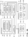
- Fig. 2A is a block diagram showing the system arrangement of the working machine 2.
- the working machine 2 includes a traveling unit 21, a working unit 22, a detection unit 23, control unit 24, and an external communication interface 25.
- the traveling unit 21 includes a left rear wheel 211L and a right rear wheel 211R, and motors 212L and 212R for driving the left and right rear wheels.
- the working unit 22 includes a blade 221 for performing lawn mowing and a motor 222 for driving the blade 221.
- the blade 221 is arranged at the bottom portion of the machine body of the working machine 2.
- the working machine 2 travels and performs lawn mowing by driving the blade 221 by the motor 222.
- the detection unit 23 includes electromagnetic wave detection units 231, an obstacle sensor 232, and a main body information sensor 233.
- the electromagnetic wave detection units 231 detect the electromagnetic waves of the station 3 and the area wire 4. In this case, the type (for example, the frequency) of the electromagnetic wave of the station 3 is different from that of the area wire 4.
- the electromagnetic wave detection units 231 can detect these electromagnetic waves while discriminating them from each other.
- the obstacle sensor 233 is a sensor for bypassing an obstacle (for example, a stone) within the working area 41.
- a main body information sensor 234 is a sensor for detecting the states of the working machine 2 itself such as the posture, vehicle speed, angular velocity, and the like of the working machine 2.
- the main body information sensor 234 includes, for example, a G sensor, a vehicle speed sensor, an angular velocity sensor, and the like. Note that various exemplified sensors are merely examples.
- the detection unit 23 can further include other sensors.
- the control unit 24 is an ECU (Electronic Control Unit) and includes a CPU (Central Processing Unit) 241 and a memory 242.
- the functions of the control unit 24 are implemented by semiconductor integrated circuits such as a PLD (Programmable Logic Device) and an ASIC (Application Specific Integrated Circuit).
- the functions of the control unit 24 may be implemented by software as another embodiment. That is, the functions of the control unit 24 can be implemented by either hardware or software.
- the external communication interface 25 is an interface for receiving input information from the user.
- the control unit 24 memorizes (stores) the input information received by the external communication interface 25 in the memory 242.
- the input information can be input using a portable terminal (for example, a portable type input terminal such as a smartphone) by the user. Accordingly, the user can input the input information without directly accessing the working machine 2 (from a location remote from the working machine or from a remote place).
- the working machine 2 may further include an input terminal for receiving this input information. In this case, the user can directly input the input information to this input terminal.
- Fig. 2B is a schematic view showing the structure of the working machine 2.
- a left front wheel 213L and a right front wheel 213R as part of the traveling unit 21 are arranged at the front left side and the front right side of the working machine 2.
- the front left wheel 213L and the front right wheel 213R are driven wheels (rotatable). That is, the body of the working machine 2 is supported by the four wheels, that is, the rear wheels 211L and 211R and the front wheels 213L and 213R.
- the rear wheels 211L and 211R are independently driven by motors 212L and 212R, respectively.
- both the rear wheels 211L and 211R are set at a rotation speed corresponding to +0.1 m/s (in this case, + indicates the rotation in the forward direction)
- the working machine 2 travels straight at a speed of 0.1 m/s.
- both the rear wheels 211L and 211R are set at a rotation speed corresponding to -0.05 m/s (in this case, - indicates the rotation in the backward direction)
- the working machine 2 travels backward at a speed of 0.05 m/s.
- the rear left wheel 211L is set at a rotation speed corresponding to +0.1 m/s
- the rear right wheel 211R is set at a rotation speed corresponding to +0.05 m/s
- the working machine 2 turns right.
- the working machine 2 further includes a battery 25 and a connector 26 for charging the battery 25.
- the connector 26 is arranged in the front side of the working machine 2.
- the working machine 2 enters the station 3 from the front side. Note that when starting the work, the working machine 2 moves backward from the station 3, turns to change the traveling direction, and moves forward, thereby starting the working machine 2 from the station 3.
- the electromagnetic wave detection units 231 are arranged on the front left side and the front right side, respectively, of the working machine 2. That is, the working machine 2 includes a total of two electromagnetic wave detection units 231.
- the electromagnetic wave detection unit 231 on the front left side is referred to as an "electromagnetic wave detection unit 231L”
- the electromagnetic wave detection unit 231 on the front right side is referred to as an “electromagnetic wave detection unit 231R" in order to discriminate them from each other. If these detection units need not be discriminated from each other, the detection units will be expressed as the "electromagnetic wave detection units 231".
- the control unit 24 can detect the position of the working machine 2 with respect to the area wire 4 based on the detection values of the electromagnetic wave detection units 231L and 231R.
- the control unit 24 determines that the working machine 2 is traveling within the working area 41. For example, when one of the detection values of the electromagnetic waves of the area wire 4 by the electromagnetic wave detection units 231L and 231R is positive and the other of the detection values is negative, the control unit 24 determines that the working machine 2 is traveling on the area wire 4 (the working machine 2 is positioned on the partition boundary of the working area 41).
- the control unit 24 determines that the working machine 2 is traveling outside the working area 41 and changes to cause the working machine 2 to return to the working area 41.
- the control unit 24 can also determine the side where the area wire 4 is positioned with respect to the traveling direction of the working machine 2 traveling within the working area 41. For example, if the detection value of the electromagnetic wave detection unit 231L is larger than the detection value of the electromagnetic wave detection unit 231R, the control unit 24 determines that the working machine 2 is traveling (in the clockwise direction (the CW direction) within the working area 41) in a state in which the working machine 2 is close to the area wire 4 on the left side of the traveling direction.
- Fig. 3 is a schematic view showing the structure of the station 3.
- the station 3 includes a charging connector 31, a station wire 32, and a docking wire 33.
- the connector 31 is arranged on the proximal portion side of the station 3 to which the area wire 4 is connected.
- the connector 26 of the working machine 2 is connected to the connector 31 of the station 3, thereby starting charging the battery 25.
- the connector 26 and the connector 31 are arranged to be insertable, and one of the connectors can be a female/male connector.
- the station wire 32 and the docking wire 33 are incorporated in the station 3 and generate electromagnetic waves of different types (for example, different frequencies). Note that the electromagnetic waves of the station wire 32 and the docking wire 33 are different from the electromagnetic wave of the area wire 4. As described above, the electromagnetic wave detection units 231 detect the electromagnetic waves while discriminating them from each other.
- the electromagnetic wave detection units 231 detect the electromagnetic wave of the station wire 32 (strictly, the detection value of the electromagnetic wave of the station wire 32 by the electromagnetic wave detection units 231 is larger than a reference value). Accordingly, the control unit 24 determines that the working machine 2 is traveling near the station 3. In other words, the station wire 32 notifies the working machine 2 traveling near the station 3 of information indicating that the working machine 2 is traveling near the station 3 by the electromagnetic wave. As described above, since the working machine 2 includes the two electromagnetic wave detection units 231L and 231R, the control unit 24 can detect the position of the working machine 2 with respect to the station 3.
- the electromagnetic wave detection units 231 detect the electromagnetic wave of the docking wire 33. Accordingly, the control unit 24 can determine whether the entrance angle of the working machine 2 with respect to the station 3 can be maintained so as to cause the connector 26 to come close to the connector 31. In other words, the docking wire 33 guides by the electromagnetic wave the working machine 2 which is entering the station 3 so as to properly connect the connector 26 and the connector 31. As described above, since the working machine 2 includes the two electromagnetic wave detection units 231L and 231R, the control unit 24 can determine the entrance angle of the working machine 2 with respect to the station 3.
- each electromagnetic wave detection unit 231 detects the electromagnetic waves of the area wire 4, the station wire 32, and the docking wire 33 while discriminating them from each other, individual dedicated sensors may be arranged for electromagnetic waves, respectively, as another embodiment.
- the control unit 24 first detects based on the electromagnetic wave of the station wire 32 that the working machine 2 is traveling near the station 3. After that, the control unit 24 decides the entrance route to the station 3 based on the installation mode of the station 3.
- the information indicating the installation mode of the station 3 is input as the input information by the user in advance before the start of the working of the working machine 2 (for example, when the working system 1 is installed) and is stored in the memory 242. For this reason, the entrance posture of the working machine 2 to the station 3 can be appropriately controlled, thereby implementing proper docking.
- the installation mode of the station 3 includes the layout of the station 3 within the working area 41.
- the installation mode includes, for example, the position and orientation (entrance enable direction of the working machine 2) of the station 3 within the working area 41, the shape of the working area 41 near the station 3, and the like.
- step S110 (to be simply referred to as "S110" hereinafter; this also applies to other steps), the working machine 2 is traveling within the working area 41 so as to return the working machine 2 to the station 3.
- S110 may be executed in a state in which working (lawn mowing) is stopped or in a state in which working is being performed.
- the control unit 24 sets the control parameter of the traveling unit 21 based on the installation mode of the station 3 and the detection value of the electromagnetic wave of the area wire 4.
- This control parameter includes parameters for deciding the traveling route (the entrance route to the station 3) and the traveling speed of the working machine 2 accessorily. More specifically, this control parameter decides the magnitudes and rotation directions of the driving forces of the motors 212L and 212R for driving the rear wheels 211L and 211R. The details will be further described by exemplifying several cases later.
- the control unit 24 decides the proper traveling route to cause the working machine 2 to come close to the station 3.
- the traveling route or entrance route may be expressed as a locus.
- the control unit 24 can determine the distance from the working machine 2 to the area wire 4 (whether the working machine 2 is near or far apart from the area wire 4) according to the detection value of the electromagnetic wave of the area wire 4.
- the control unit 24 causes the information acquisition unit 2413 to acquire the information indicating the installation mode of the station 3 prestored in the memory 242, and sets the control parameter (decides the traveling route) together with the determination result.
- This control parameter may be set based on the installation mode of the station 3 such as a look-up table or may be set by calculation of predetermined arithmetic processing.
- control parameter may be changed over time, for example, upon the elapse of a predetermined time. Accordingly, for example, traveling routes coping with various installation modes of the station 3 such as the left turn after the right turn can be implemented.
- traveling speed can be determined based on the traveling route. For example, if a turning radius is small, the traveling speed may be determined so as to reduce the traveling speed.
- the detection value (D ST ) of the electromagnetic wave of the station wire 32 may further be used together with the detection value of the electromagnetic wave of the area wire 4.
- the control unit 24 can determine the position of the working machine 2 with respect to the station 3 within the working area 41. An appropriate control parameter can be set even by this method.
- control unit 24 sets the control parameter of the traveling unit 21 based on the installation mode of the station 3.
- the working machine 2 further comes close to the station 3 and has moved to the position where the working machine 2 can easily enter into the station 3.
- the control unit 24 sets the control parameter of the traveling unit 21 so as to implement appropriate docking by causing the working machine 2 to start entering into the station 3 from that position.
- the control parameter may be set by referring to a look-up table or by calculation of the predetermined arithmetic processing based on the installation mode of the station 3.
- traveling is performed as in S110 and S140. This traveling is performed based on the control parameter set in S160. Accordingly, the working machine 2 enters into the station 3 and travels on the station 3 while being guided by the electromagnetic wave of the docking wire 33.
- the control unit 24 may lose the electromagnetic wave of the docking wire 33 due to, for example, mixing of another electromagnetic noise.
- the control unit 24 interrupts entrance of the working machine 2 or searches for the electromagnetic wave of the docking wire 33 for a predetermined time while rotating the working machine 2 at the position where the electromagnetic wave of the docking wire 33 is lost.
- the rotation of the working machine 2 can be executed such that the rear left wheel 211L is rotated at a speed corresponding to +0.05 m/s and the rear right wheel 211R is rotated at a speed corresponding to -0.05 m/s. If the electromagnetic wave of the docking wire 33 is detected again, the control unit 24 restarts the entrance of the working machine 2.
- control unit 24 determines whether docking is completed. If NO in S180, the process returns to S170; otherwise, this traveling control ends.
- the working machine 2 is further moved close to the station 3 in the route decided based on the installation mode of the station 3.
- the working machine 2 is moved to a position where it can easily enter into the station 3.
- the working machine 2 comes close to the station 3 (that is, in response to establishment of D ST > D ST_REF1 )
- the working machine 2 starts to enter into the station 3 in the route decided based on the installation mode of the station 3.
- the working machine 2 travels on the station 3 while being guided by the electromagnetic wave of the docking wire 33, thereby implementing appropriate docking.
- the information indicating the installation mode of the station 3 can be prestored by the user, and the control unit 24 can control the entrance posture of the working machine 2 to the station 3 by referring to this information.
- Fig. 5A shows the standard installation layout (standard installation type) of the station 3. That is, the station 3 is installed in a direction perpendicular to the extending direction of the area wire 4. The working machine 2 enters into the station 3 in a direction almost perpendicular to the extending direction of the area wire 4.
- Case1 (to be simply referred to as Case1 hereinafter; this also applied to other cases)
- Case1 the traveling working machine 2 enters into the station 3 in the CW direction within the working area 41 at a position relatively apart from the area wire 4.
- the control unit 24 can determine that the working machine 2 is traveling in the CW direction.
- the control parameter is set based on the installation mode of the station 3 prestored in the memory 241 and the detection value (that is, the distance from the working machine 2 to the area wire 4) of the electromagnetic value of the area wire 4.
- the traveling route for making the working machine 2 come closer to the station 3 is decided.
- the turning radius and the traveling speed for making the working machine 2 come closer to the station 3 a timing for changing the turning angle during turning, and the like are decided.
- the control parameter is decided so as to relatively moderately turn the working machine 2 because the working machine 2 is traveling at a position relatively separated from the area wire 4 in Case1.
- Case2 assume that the working machine 2 enters into the station 3 in the CW direction within the working area 41 at a position relatively near the area wire 4.
- the working machine 2 since the working machine 2 is traveling at the position relatively separated from the area wire 4, the working machine 2 can be moved to the position P1 near the front side of the station 3 by causing the working machine 2 to turn relatively moderately (see Act12).
- the working machine 2 since the working machine 2 is traveling at a position relatively near the area wire 4, a relatively abrupt turn is required to move the working machine 2 to the position P1 near the front side of the station 3.
- the working machine 2 can move to the position P1 near the front side of the station 3 (corresponding to S140 in Fig. 4 ). After the working machine 2 moves up to the position P1, the working machine 2 enters into the station 3 in the same procedure as in Act13 of Case1, thereby completing docking (corresponding to S150 to S180 in Fig. 4 ).
- the control unit 24 refers to the installation mode of the station 3 prestored in the memory 241, thereby setting the control parameter of the traveling unit 21 and deciding the entrance route of the working machine 2 into the station 3. Accordingly, the entrance posture of the working machine 2 when entering into the station 3 can be controlled.
- the working machine 2 is moved to the position P1 near the front side of the station 3 after the detection of the electromagnetic wave of the station wire 32, then turns to face the front side of the station 3, and enters into the station 3. Therefore, appropriate docking can be implemented in each of Case1 and Case2.
- Fig. 5B shows a mode in which the working machine 2 traveling in the CCW direction enters the station 3 in the layout of the standard installation type (as in Fig. 5A ).
- Case3 shows a case in which the working machine 2 traveling in the CCW direction within the working area 41 at a position relatively away from the area wire 4 enters the station 3.
- Case4 shows a case in which the working machine 2 traveling in the CCW direction within the working area 41 at a position relatively near the area wire 4 enters into the station 3.
- Fig. 5C shows the layout in which the station 3 is installed in a posture parallel to the extending direction of the area wire 4 (lateral installation type).
- the side which allows entrance of the working machine 2 is the right side.
- the side which allows entrance of the working machine 2 into the station 3 corresponds to the traveling direction of the working machine 2, and working machine 2 can relatively easily enter into the station 3.
- the side which allows entrance of the working machine 2 into the station 3 does not correspond to the traveling direction of the working machine 2. For this reason, a relatively abrupt turn is required.
- the control unit 24 can determine using the electromagnetic wave detection units 231L and 231R that the working machine 2 is traveling in the CW direction. Accordingly, in Act51, upon detection of the electromagnetic wave of the station wire 32, the control unit 24 sets the control parameter for implementing the following traveling route based on the above detection and the prestored installation mode (that is, the station 3 is set as the lateral installation type) of the station 3. As described above, in Case5 the side which allows entrance of the working machine 2 into the station 3 corresponds to the traveling direction of the working machine 2. Therefore, upon detection of the electromagnetic wave of the station wire 32, the control unit 24 can relatively easily move the working machine 2 to a position P3 near the front side of the station 3 in Act52.
- the control unit 24 can determine using the two electromagnetic wave detection units 231L and 231R that the working machine 2 is traveling in the CCW direction.
- the control unit 24 sets the control parameter which implements the following traveling route based on the above detection and the prestored installation mode of the station 3. As described above, in Case6, the side which allows entrance of the working machine 2 into the station 3 does not correspond to the traveling direction of the working machine 2.
- the control unit 24 makes the working machine 2 turn left so as to keep the distance to the station 3, and moves the working machine 2 to a position P4 lateral to the station 3 in Act62.
- This position P4 is an allowable position where each electromagnetic wave detection unit 231 can appropriately detect the electromagnetic wave of the docking wire 33 by making the working machine 2 turn right in Act63.
- the position P4 is a position on the right side of the allowable position in Fig. 5C .
- the control unit 24 refers to the installation mode of the station 3 prestored in the memory 241, thereby setting the control parameter of the traveling unit 21 and deciding the entrance route of the working machine 2 into the station 3. Accordingly, the entrance posture of the working machine 2 when entering into the station 3 can be controlled.
- the working machine 2 moves to the position P3 near the front side of the station 3 (corresponding to S120 to S140 in Fig. 4 ). After that, the working machine 2 turns to face the front side of the station 3 and enters into the station 3 (corresponding to S150 to S180 in Fig. 4 ). According to Case5, appropriate docking can be implemented.
- the working machine 2 upon detection of the electromagnetic wave of the station wire 32, the working machine 2 moves to the position P4 lateral to the station 3 while maintaining the distance to the station 3 (corresponding to S120 to S140 in Fig. 4 ). After that, the working machine 2 turns right and enters into the station 3 (corresponding to S150 to S180 in Fig. 4 ).
- the position P4 can be an allowable position where each electromagnetic wave detection unit 231 can appropriately detect the electromagnetic wave of the docking wire 33 by making the working machine 2 turn right as described above.
- the position P4 can be a position on the right side of the allowable position. Therefore, even in Case6, the working machine 2 can appropriately enter into the station 3 and can perform appropriate docking.
- Fig. 6A shows a layout (convex portion installation type) in which the working area 41 has a portion partitioned in a convex shape (alcove shape) and the station 3 is installed in this portion.
- the traveling direction of the working machine 2 is the CW direction
- the traveling direction of the working machine 2 is the CCW direction except that the traveling directions of the working machine 2 are opposite to each other. For this reason, only the case in which the traveling direction is the CW direction will be considered.
- Case7 assume that the working machine 2 traveling in the CW direction at a position relatively apart from the area wire 4 enters into the station 3.
- an influence of the installation mode of the station 3 as the convex portion installation type is relatively small. That is, Case7 is the same as Case1 as the standard installation type described with reference to Fig. 5A .
- the control unit 24 sets the control parameter for implementing the following traveling route based on the prestored installation mode of the station 3 and the detection value of the electromagnetic wave of the area wire 4. That is, in Act72, the working machine 5 relatively moderately turns left to move to a position P5 near the front side of the station 3. After that, the working machine 2 enters into the station 3 in the same procedure as in Act13 of Case1, thus completing docking.
- the working machine 5 travels straight along the extending direction of the area wire 4, passes by the corner of the area wire 4, and moves to a position P6.
- the position 6 is located on the right side of the position P5 near the front side of the station 3 in this example.
- the position 6 can be any position where each electromagnetic wave detection unit 231 can appropriately detects the electromagnetic wave of the docking wire 33 by causing the working machine 2 to turn left in Act83 to be performed next.
- Act93 the working machine 2 turns right to bypass the concave shape.
- Act94 the working machine 2 turns right and moves to a position P8 near the front side of the station 3.
- Act95 the working machine 2 turns to face the front side of the station 3 and enters into the station 3. Act94 and Act95 are performed in the same procedure as that of Act12 and Act13 in Case1 described above.
- the control unit 24 refers to the prestored installation mode of the station 3. This makes it possible to control the entrance posture of the working machine 2 when entering into the station 3.
- Fig. 6C shows a layout (folded portion installation type) in which the area wire 4 is arranged to be folded, two different portions in the area wire 4 extend parallel, and the station 3 is installed on one of the two different portions (folded portion installation type).
- the electromagnetic wave of the station wire 32 may be detected while the working machine 2 is traveling on the opposite side of the station 3 with respect to the folded area wire 4. In this case, the working machine 2 cannot return to the station 3 because the working machine 2 travels within the working area 41.
- the installation modes of the station 3 can be classified into several types to facilitate setting of the control parameter of the traveling unit 21 (that is, the decision of the entrance route into the station 3).
- the standard installation type see Figs. 5A and 5B
- the lateral installation type see Fig. 5C
- the convex portion installation type see Fig. 6A
- the concave portion adjacent installation type see Fig. 6B
- the folded portion installation type see Fig. 6C
- the control unit 24 may lose the electromagnetic wave of the station wire 32 due to mixing of another electromagnetic noise or the like.
- the control unit 24 may interrupt the traveling control for entering the working machine 2 into the station 3 and, for example, searches for the electromagnetic wave of the station wire 32 while rotating the working machine 2 for a predetermined time at the current position.
- the rotation of the working machine 2 can be executed such that, for example, the rear left wheel 211L is rotated at a speed corresponding to +0.05 m/s and the rear right wheel 211R is rotated at a speed corresponding to -0.05 m/s. If the electromagnetic wave of the station wire 32 is detected again, the control unit 24 restarts the above traveling control.
- a working system for example, 1) comprising a self-propelled working machine (for example, 2) and a station (for example, 3) configured to charge the working machine by connecting the working machine to the station, wherein the working machine comprises a traveling unit (for example, 21), a traveling control unit (for example, 24, 241, 2411) configured to control the traveling unit, a detection unit (for example, 23, 231) configured to detect the station, and an information acquisition unit (for example, 24, 241, 2413), the information acquisition unit acquires input information input by a user, the input information includes information indicating an installation mode of the station, and the traveling control unit sets a control parameter of the traveling unit based on the installation mode of the station in response to detection of the station by the detection unit.
- the traveling unit for example, 21
- a traveling control unit for example, 24, 241, 2411
- a detection unit for example, 23, 231
- an information acquisition unit for example, 24, 241, 2413
- the working machine decides the entrance route based on the layout of the station in the working area.
- the layout is the position of the station in the working area, its posture (that is, the direction in which the working machine can enter), the shape of the working area, and the like.
- the working machine comprises a lawn mower (for example, 2).
- the working machine is applied to the lawn mower.
- Another application example is a cleaning robot for performing automatic cleaning within a predetermined area, or the like.
- the station In the fourth mode, the station generates an electromagnetic wave (for example, a magnetic field), and the detection unit is configured to detect the electromagnetic wave from the station.
- an electromagnetic wave for example, a magnetic field
- the working machine can detect the station based on the electromagnetic wave from the station using the detection unit.
- the working machine detects the station (detects that the working machine is traveling near the station), and the entrance route is decided in response to this detection.
- the traveling control unit further sets a control parameter of the traveling unit based on a detection value (intensity) of the electromagnetic wave by the detection unit.
- the working machine can decide the entrance route based on the detection value of the electromagnetic wave.
- the intensity of the electromagnetic wave is made small (weak) when the distance from the station increases. For this reason, the working machine can decided the entrance route based on the detection value of the electromagnetic wave, that is, the distance to the station.
- the station In the sixth mode, the station generates a plurality of types (for example frequencies) of electromagnetic waves, and the traveling control unit sets a control parameter of the traveling unit in response to detection of one of the plurality of types of electromagnetic waves by the detection unit.
- types for example frequencies
- the working machine can decide the entrance route based on the type of electromagnetic wave.
- the working system further comprises an area wire (for example, 4) configured to partition the working area (for example, 41) of the working machine, the area wire generates an electromagnetic wave, the detection unit is further configured to detect the electromagnetic wave from the area wire, and the traveling control unit further sets the control parameter of the traveling unit based on an intensity of the electromagnetic wave from the area wire which is detected by the detection unit.
- an area wire for example, 4
- the detection unit is further configured to detect the electromagnetic wave from the area wire
- the traveling control unit further sets the control parameter of the traveling unit based on an intensity of the electromagnetic wave from the area wire which is detected by the detection unit.
- the working machine can decide the entrance route to the station based on the intensity of the electromagnetic wave of the area wire, that is, the distance from the area wire.
- control parameter is a parameter for deciding a traveling route (locus) of the working machine to the station.
- the working machine decides the traveling route to the station using the control parameter.
- the traveling speed of the working machine is also decided additionally. For example, when the working machine turns toward the station, a specific turning radius and a specific turning speed (more specifically, for example, if the turning radius is small, the traveling speed is low) are decided.
- the traveling unit includes wheels (for example, 211L, 211R) and motors (for example, 212L, 212R) configured to drive the wheels, and the control parameter includes magnitudes of driving forces of the motors and rotation directions of the wheels.
- the traveling unit includes the wheels and the motors.
- the turning radius and the traveling speed are decided in accordance with the driving forces (rotation speeds of the wheels) of the motors and the rotation directions of the wheels. For example, if the left wheel (for example, 211L) is rotated corresponding to +0.1 m/s and the right wheel (for example, 211R) is rotated at a rotation speed corresponding to +0.05 m/s, the working machine turns right.
- the input information is input using a portable terminal of the user.
- the portable terminal is a portable type terminal such as a smartphone.
- the user can input the input information without directly accessing the working machine (that is, from the location remote from the working machine).
- the user can set the working time such as a working start time and a working end time other than information indicating the installation mode of the station.
- a chargeable self-propelled working machine for example, 2 by being connected to a station (for example, 3), comprising storage means (for example, 242) for storing information indicating an installation mode of the station, traveling means (for example, 21) for traveling the working machine, and control means (for example, 2411) for controlling the traveling means, wherein the installation mode of the station is set in the storage means by a user in advance, and the control means controls an entrance posture of the working machine into the station based on the installation mode of the station.
- storage means for example, 242
- traveling means for example, 21
- control means for example, 2411
- the installation mode of the station is set in the storage means of the working machine in advance, and the working machine appropriately controls the entrance posture of the working machine into the station based on this installation mode. Therefore, appropriate connection of the working machine to the station can be implemented.
- the working machine further comprises communication means (for example, 25) for receiving the information indicating the installation mode of the station from a portable terminal of the user.
- the user can input information indicating the installation mode of the station without directly accessing the working machine.
Landscapes
- Engineering & Computer Science (AREA)
- Physics & Mathematics (AREA)
- Aviation & Aerospace Engineering (AREA)
- Radar, Positioning & Navigation (AREA)
- Remote Sensing (AREA)
- General Physics & Mathematics (AREA)
- Automation & Control Theory (AREA)
- Electromagnetism (AREA)
- Control Of Position, Course, Altitude, Or Attitude Of Moving Bodies (AREA)
- Guiding Agricultural Machines (AREA)
Abstract
Description
- The present invention relates to a working system and a working machine.
-
PTL 1 describes the structure of an unmanned traveling working machine (for example, a lawn mower). According to PTL 1, the working machine automatically performs a work (for example, lawn mowing) within a working area. More specifically, the working area is partitioned by a wire (an area wire). The working machine travels within the working area by detecting an electromagnetic wave from an area wire. If the working machine falls outside the working area, the working machine travels to return to the working area. - PTL 1: Japanese Patent No.
5828776 - According to PTL 1, a battery is incorporated into the working machine. When the remaining amount of the battery becomes lower than a reference value, the working machine returns to a station (a charger) based on the electromagnetic wave of the area wire. When the working machine is connected to the station, charging of the battery is started. In this case, after the working machine returns near the station, the appropriate contact with the station may not be achieved if the entrance posture of the working machine to the station is not appropriate.
- It is an object of the present invention to control the entrance posture of the working machine to the station.
- According to the first aspect of the present invention, there is provided a working system comprising a self-propelled working machine and a station configured to charge the working machine by connecting the working machine to the station, characterized in that the working machine comprises a traveling unit, a traveling control unit configured to control the traveling unit, a detection unit configured to detect the station, and an information acquisition unit, the information acquisition unit acquires input information which is input by a user, the input information includes information indicating an installation mode of the station, and the traveling control unit sets a control parameter of the traveling unit based on the installation mode of the station in response to detection of the station by the detection unit.
- According to the present invention, the entrance posture of the working machine to the station can be controlled.
-
-
Fig. 1 is a view for explaining the arrangement example of an automatic working system comprising a working machine and a station; -
Figs. 2A and2B are views for explaining the arrangement example of the working machine; -
Fig. 3 is a view for explaining the arrangement example of the station; -
Fig. 4 is a flowchart for explaining the traveling control sequence of the working machine; -
Figs. 5A, 5B, and 5C are views for explaining several examples of the installation modes of the station; and -
Figs. 6A, 6B, and 6C are views for explaining several examples of the installation modes of the station. - An embodiment of the present invention will now be described with reference to the accompanying drawings. Note that the drawings are schematic views showing structures or arrangements according to the embodiment, and the dimensions of members shown in the drawings do not necessarily reflect the actuality. In addition, the same reference numerals denote the same members or same constituent elements in the drawings, and a repetitive description in this specification will be omitted.
-
Fig. 1 is a schematic view showing the arrangement of aworking system 1 according to an embodiment. Theworking system 1 includes aworking machine 2, astation 3, and anarea wire 4. The workingmachine 2 is a self-propelled unmanned working robot and performs a work while running based on a predetermined operation sequence. The workingmachine 2 is a lawn mower for performing lawn mowing according to this embodiment. The workingmachine 2 may be a cleaning robot for performing cleaning as another embodiment. Note that an arrow inFig. 1 indicates the traveling direction of theworking machine 2. - The
station 3 is a charger for charging the workingmachine 2 by connecting theworking machine 2 to thestation 3. Although described in detail later, thestation 3 generates an electromagnetic wave (for example, a magnetic field), and theworking machine 2 can enter thestation 3 by detecting thestation 3 based on this electromagnetic wave. Thearea wire 4 is a wire for partitioning aworking area 41 of theworking machine 2. InFig. 1 , part of thearea wire 4 is illustrated, but the wire is arranged integrally in a ring shape. Thearea wire 4 is connected to thestation 3 and generates an electromagnetic wave upon reception of the power from thestation 3. The workingmachine 2 detects the electromagnetic wave of thearea wire 4 to perform a work (lawn mowing in this embodiment) within theworking area 41. If theworking machine 2 falls outside theworking area 41, theworking machine 2 travels so as to return to theworking area 41. Thearea wire 4 is generally installed under the ground in a yard, but may be exposed from the ground surface. -
Fig. 2A is a block diagram showing the system arrangement of theworking machine 2. Theworking machine 2 includes atraveling unit 21, aworking unit 22, adetection unit 23,control unit 24, and anexternal communication interface 25. Thetraveling unit 21 includes a leftrear wheel 211L and a rightrear wheel 211R, andmotors unit 22 includes ablade 221 for performing lawn mowing and amotor 222 for driving theblade 221. Theblade 221 is arranged at the bottom portion of the machine body of theworking machine 2. The workingmachine 2 travels and performs lawn mowing by driving theblade 221 by themotor 222. - The
detection unit 23 includes electromagneticwave detection units 231, anobstacle sensor 232, and a mainbody information sensor 233. The electromagneticwave detection units 231 detect the electromagnetic waves of thestation 3 and thearea wire 4. In this case, the type (for example, the frequency) of the electromagnetic wave of thestation 3 is different from that of thearea wire 4. The electromagneticwave detection units 231 can detect these electromagnetic waves while discriminating them from each other. Theobstacle sensor 233 is a sensor for bypassing an obstacle (for example, a stone) within theworking area 41. A main body information sensor 234 is a sensor for detecting the states of theworking machine 2 itself such as the posture, vehicle speed, angular velocity, and the like of theworking machine 2. The main body information sensor 234 includes, for example, a G sensor, a vehicle speed sensor, an angular velocity sensor, and the like. Note that various exemplified sensors are merely examples. Thedetection unit 23 can further include other sensors. - The
control unit 24 is an ECU (Electronic Control Unit) and includes a CPU (Central Processing Unit) 241 and amemory 242. The functions of thecontrol unit 24 are implemented by semiconductor integrated circuits such as a PLD (Programmable Logic Device) and an ASIC (Application Specific Integrated Circuit). However, the functions of thecontrol unit 24 may be implemented by software as another embodiment. That is, the functions of thecontrol unit 24 can be implemented by either hardware or software. - According to this embodiment, the
CPU 241 can function as a travelingcontrol unit 2411, a workingcontrol unit 2412, and aninformation acquisition unit 2413. For example, theCPU 241 functions as the travelingcontrol unit 2411 to control the travelingunit 21. TheCPU 241 functions as the workingcontrol unit 2412 to control the workingunit 22. TheCPU 241 functions as theinformation acquisition unit 2413 to acquire necessary information from thememory 242. For the descriptive convenience, the following description will be made using thecontrol unit 24 as the control entity. - The
external communication interface 25 is an interface for receiving input information from the user. Thecontrol unit 24 memorizes (stores) the input information received by theexternal communication interface 25 in thememory 242. According to this embodiment, the input information can be input using a portable terminal (for example, a portable type input terminal such as a smartphone) by the user. Accordingly, the user can input the input information without directly accessing the working machine 2 (from a location remote from the working machine or from a remote place). As another embodiment, the workingmachine 2 may further include an input terminal for receiving this input information. In this case, the user can directly input the input information to this input terminal. -
Fig. 2B is a schematic view showing the structure of the workingmachine 2. Aleft front wheel 213L and a rightfront wheel 213R as part of the travelingunit 21 are arranged at the front left side and the front right side of the workingmachine 2. The frontleft wheel 213L and the frontright wheel 213R are driven wheels (rotatable). That is, the body of the workingmachine 2 is supported by the four wheels, that is, therear wheels front wheels rear wheels motors - For example, when both the
rear wheels machine 2 travels straight at a speed of 0.1 m/s. In addition, when both therear wheels machine 2 travels backward at a speed of 0.05 m/s. For example, when the rearleft wheel 211L is set at a rotation speed corresponding to +0.1 m/s and the rearright wheel 211R is set at a rotation speed corresponding to +0.05 m/s, the workingmachine 2 turns right. For example, when the rearleft wheel 211L is set at a rotation speed corresponding to +0.05 m/s and the rearright wheel 211R is set at a rotation speed corresponding to -0.05 m/s, the workingmachine 2 rotates clockwise at the same position. - The working
machine 2 further includes abattery 25 and aconnector 26 for charging thebattery 25. Theconnector 26 is arranged in the front side of the workingmachine 2. When charging the workingmachine 2, the workingmachine 2 enters thestation 3 from the front side. Note that when starting the work, the workingmachine 2 moves backward from thestation 3, turns to change the traveling direction, and moves forward, thereby starting the workingmachine 2 from thestation 3. - As shown in
Fig. 2B , according to this embodiment, the electromagneticwave detection units 231 are arranged on the front left side and the front right side, respectively, of the workingmachine 2. That is, the workingmachine 2 includes a total of two electromagneticwave detection units 231. The electromagneticwave detection unit 231 on the front left side is referred to as an "electromagneticwave detection unit 231L", and the electromagneticwave detection unit 231 on the front right side is referred to as an "electromagneticwave detection unit 231R" in order to discriminate them from each other. If these detection units need not be discriminated from each other, the detection units will be expressed as the "electromagneticwave detection units 231". Thecontrol unit 24 can detect the position of the workingmachine 2 with respect to thearea wire 4 based on the detection values of the electromagneticwave detection units - For example, when the detection values of the electromagnetic waves of the
area wire 4 by the electromagneticwave detection units control unit 24 determines that the workingmachine 2 is traveling within the workingarea 41. For example, when one of the detection values of the electromagnetic waves of thearea wire 4 by the electromagneticwave detection units control unit 24 determines that the workingmachine 2 is traveling on the area wire 4 (the workingmachine 2 is positioned on the partition boundary of the working area 41). In addition, for example, when the detection values of the electromagnetic waves of thearea wire 4 by the electromagneticwave detection units control unit 24 determines that the workingmachine 2 is traveling outside the workingarea 41 and changes to cause the workingmachine 2 to return to the workingarea 41. - For example, when the detection values of the electromagnetic waves of the
area wire 4 by the electromagneticwave detection units control unit 24 can also determine the side where thearea wire 4 is positioned with respect to the traveling direction of the workingmachine 2 traveling within the workingarea 41. For example, if the detection value of the electromagneticwave detection unit 231L is larger than the detection value of the electromagneticwave detection unit 231R, thecontrol unit 24 determines that the workingmachine 2 is traveling (in the clockwise direction (the CW direction) within the working area 41) in a state in which the workingmachine 2 is close to thearea wire 4 on the left side of the traveling direction. On the other hand, if the detection value of the electromagneticwave detection unit 231L is smaller than the detection value of the electromagneticwave detection unit 231R, thecontrol unit 24 determines that the workingmachine 2 is traveling (in the counterclockwise direction (the CCW direction) within the working area 41) in a state in which the workingmachine 2 is close to thearea wire 4 on the right side of the traveling direction. -
Fig. 3 is a schematic view showing the structure of thestation 3. Thestation 3 includes a chargingconnector 31, astation wire 32, and adocking wire 33. Theconnector 31 is arranged on the proximal portion side of thestation 3 to which thearea wire 4 is connected. When the workingmachine 2 enters into thestation 3, theconnector 26 of the workingmachine 2 is connected to theconnector 31 of thestation 3, thereby starting charging thebattery 25. Note that theconnector 26 and theconnector 31 are arranged to be insertable, and one of the connectors can be a female/male connector. - The
station wire 32 and thedocking wire 33 are incorporated in thestation 3 and generate electromagnetic waves of different types (for example, different frequencies). Note that the electromagnetic waves of thestation wire 32 and thedocking wire 33 are different from the electromagnetic wave of thearea wire 4. As described above, the electromagneticwave detection units 231 detect the electromagnetic waves while discriminating them from each other. - For example, if a distance from the working
machine 2 to thestation 3 is smaller than a predetermined value, the electromagneticwave detection units 231 detect the electromagnetic wave of the station wire 32 (strictly, the detection value of the electromagnetic wave of thestation wire 32 by the electromagneticwave detection units 231 is larger than a reference value). Accordingly, thecontrol unit 24 determines that the workingmachine 2 is traveling near thestation 3. In other words, thestation wire 32 notifies the workingmachine 2 traveling near thestation 3 of information indicating that the workingmachine 2 is traveling near thestation 3 by the electromagnetic wave. As described above, since the workingmachine 2 includes the two electromagneticwave detection units control unit 24 can detect the position of the workingmachine 2 with respect to thestation 3. - For example, when the working
machine 2 enters into thestation 3, the electromagneticwave detection units 231 detect the electromagnetic wave of thedocking wire 33. Accordingly, thecontrol unit 24 can determine whether the entrance angle of the workingmachine 2 with respect to thestation 3 can be maintained so as to cause theconnector 26 to come close to theconnector 31. In other words, thedocking wire 33 guides by the electromagnetic wave the workingmachine 2 which is entering thestation 3 so as to properly connect theconnector 26 and theconnector 31. As described above, since the workingmachine 2 includes the two electromagneticwave detection units control unit 24 can determine the entrance angle of the workingmachine 2 with respect to thestation 3. - In the following description, a state in which the
connector 26 and theconnector 31 are connected to each other to allow charging of thebattery 25 is referred to as "docking" in some cases. - Note that in this embodiment, although each electromagnetic
wave detection unit 231 detects the electromagnetic waves of thearea wire 4, thestation wire 32, and thedocking wire 33 while discriminating them from each other, individual dedicated sensors may be arranged for electromagnetic waves, respectively, as another embodiment. -
Fig. 4 is a flowchart showing a traveling control sequence for properly implementing docking. This traveling control is started in response to the fact that the remaining amount of thebattery 25 is smaller than the reference value, the fact that the working time of the workingmachine 2 ends, or the like. Note that the reference value of the remaining amount can be set as a value by which the workingmachine 2 can return to thestation 3 from any position of the workingarea 41. In addition, the working time (for example, a start time, an execution time, and an end time) can be set in advance by causing the user to input the working time using a portable terminal. - As the outline of this traveling control, the
control unit 24 first detects based on the electromagnetic wave of thestation wire 32 that the workingmachine 2 is traveling near thestation 3. After that, thecontrol unit 24 decides the entrance route to thestation 3 based on the installation mode of thestation 3. The information indicating the installation mode of thestation 3 is input as the input information by the user in advance before the start of the working of the working machine 2 (for example, when the workingsystem 1 is installed) and is stored in thememory 242. For this reason, the entrance posture of the workingmachine 2 to thestation 3 can be appropriately controlled, thereby implementing proper docking. The installation mode of thestation 3 includes the layout of thestation 3 within the workingarea 41. For example, the installation mode includes, for example, the position and orientation (entrance enable direction of the working machine 2) of thestation 3 within the workingarea 41, the shape of the workingarea 41 near thestation 3, and the like. - In step S110 (to be simply referred to as "S110" hereinafter; this also applies to other steps), the working
machine 2 is traveling within the workingarea 41 so as to return the workingmachine 2 to thestation 3. S110 may be executed in a state in which working (lawn mowing) is stopped or in a state in which working is being performed. - In S120, the
control unit 24 determines whether the detection value (to be referred to as DST) of the electromagnetic wave of thestation wire 32 by each electromagneticwave detection unit 231 is larger than a reference value (to be referred to as DST_REF1). In general, the distance between the workingmachine 2 and thestation 3 decreases, the intensity (the absolute value) of the electromagnetic wave of thestation wire 32 increases. For this reason, if the detection value DST is set larger than the reference value DST_REF1, it is said that the workingmachine 2 is located near the station 3 (the workingmachine 2 enters the range of the predetermined distance from the station 3). If DST > DST_REF1 is satisfied, the process advances to S130; otherwise, the process returns to S110 (the workingmachine 2 continues to search for the station 3). - In S130, the
control unit 24 sets the control parameter of the travelingunit 21 based on the installation mode of thestation 3 and the detection value of the electromagnetic wave of thearea wire 4. This control parameter includes parameters for deciding the traveling route (the entrance route to the station 3) and the traveling speed of the workingmachine 2 accessorily. More specifically, this control parameter decides the magnitudes and rotation directions of the driving forces of themotors rear wheels unit 21, thecontrol unit 24 decides the proper traveling route to cause the workingmachine 2 to come close to thestation 3. The traveling route or entrance route may be expressed as a locus. - The
control unit 24 can determine the distance from the workingmachine 2 to the area wire 4 (whether the workingmachine 2 is near or far apart from the area wire 4) according to the detection value of the electromagnetic wave of thearea wire 4. Thecontrol unit 24 causes theinformation acquisition unit 2413 to acquire the information indicating the installation mode of thestation 3 prestored in thememory 242, and sets the control parameter (decides the traveling route) together with the determination result. This control parameter may be set based on the installation mode of thestation 3 such as a look-up table or may be set by calculation of predetermined arithmetic processing. - Note that the control parameter may be changed over time, for example, upon the elapse of a predetermined time. Accordingly, for example, traveling routes coping with various installation modes of the
station 3 such as the left turn after the right turn can be implemented. In addition, the traveling speed can be determined based on the traveling route. For example, if a turning radius is small, the traveling speed may be determined so as to reduce the traveling speed. - In S130, as another embodiment, in order to set the control parameter, the detection value (DST) of the electromagnetic wave of the
station wire 32 may further be used together with the detection value of the electromagnetic wave of thearea wire 4. As described above, since the workingmachine 2 includes the electromagneticwave detection units control unit 24 can determine the position of the workingmachine 2 with respect to thestation 3 within the workingarea 41. An appropriate control parameter can be set even by this method. - In S140, traveling is performed as in S110. This traveling is performed by the control parameter set in S130, and accordingly, the working
machine 2 can further move near thestation 3. - In S150, the
control unit 24 determines whether the detection value DST of the electromagnetic wave of thestation wire 32 by each electromagneticwave detection unit 231 is set larger than a reference value (DST_REF2 (> DST_REF1). If the detection value DST is set larger than the reference value DST_REF2, it can be said that the workingmachine 2 is further moved near thestation 3 or the preparation for the start of entrance of the workingmachine 2 to thestation 3 is completed. If DST > DST_REF2 is satisfied, the process advances to S160; otherwise, the process returns to S140 (the workingmachine 2 continuously travels to further come close to the station 3). Details will be described later by exemplifying several cases. In S150, since the workingmachine 2 further comes close to thestation 3 using the control parameter set in S130, the workingmachine 2 can move to a position where the workingmachine 2 can easily enter into thestation 3. - In S160, the
control unit 24 sets the control parameter of the travelingunit 21 based on the installation mode of thestation 3. In S150, the workingmachine 2 further comes close to thestation 3 and has moved to the position where the workingmachine 2 can easily enter into thestation 3. Thecontrol unit 24 sets the control parameter of the travelingunit 21 so as to implement appropriate docking by causing the workingmachine 2 to start entering into thestation 3 from that position. As in S130, the control parameter may be set by referring to a look-up table or by calculation of the predetermined arithmetic processing based on the installation mode of thestation 3. - In S170, traveling is performed as in S110 and S140. This traveling is performed based on the control parameter set in S160. Accordingly, the working
machine 2 enters into thestation 3 and travels on thestation 3 while being guided by the electromagnetic wave of thedocking wire 33. - Note that in S170, the
control unit 24 may lose the electromagnetic wave of thedocking wire 33 due to, for example, mixing of another electromagnetic noise. In this case, thecontrol unit 24 interrupts entrance of the workingmachine 2 or searches for the electromagnetic wave of thedocking wire 33 for a predetermined time while rotating the workingmachine 2 at the position where the electromagnetic wave of thedocking wire 33 is lost. The rotation of the workingmachine 2 can be executed such that the rearleft wheel 211L is rotated at a speed corresponding to +0.05 m/s and the rearright wheel 211R is rotated at a speed corresponding to -0.05 m/s. If the electromagnetic wave of thedocking wire 33 is detected again, thecontrol unit 24 restarts the entrance of the workingmachine 2. - In S180, the
control unit 24 determines whether docking is completed. If NO in S180, the process returns to S170; otherwise, this traveling control ends. - In summary, if the
control unit 24 is traveling near the station 3 (that is, in response to establishment of DST > DST_REF1), the workingmachine 2 is further moved close to thestation 3 in the route decided based on the installation mode of thestation 3. The workingmachine 2 is moved to a position where it can easily enter into thestation 3. After the workingmachine 2 comes close to the station 3 (that is, in response to establishment of DST > DST_REF1), the workingmachine 2 starts to enter into thestation 3 in the route decided based on the installation mode of thestation 3. After that, the workingmachine 2 travels on thestation 3 while being guided by the electromagnetic wave of thedocking wire 33, thereby implementing appropriate docking. The information indicating the installation mode of thestation 3 can be prestored by the user, and thecontrol unit 24 can control the entrance posture of the workingmachine 2 to thestation 3 by referring to this information. - In this embodiment, the control parameter is set twice, that is, when DST > DST_REF1 (S120) is satisfied and when DST > DST_REF2 (S150) is satisfied. The number of times of the settings may be one or three or more. In addition, in this embodiment, the mode in which the control parameter is set based on the intensity (that is, the detection value DST) of the electromagnetic wave of the
station wire 32 is exemplified. However, the present invention is not limited to this. For example, as another embodiment, thestation wire 32 may output a plurality of electromagnetic waves having different types. In this case, the output distances of the plurality of electromagnetic waves are different from each other. Thecontrol unit 24 sets the control parameter in accordance with the detection of the distances by the electromagneticwave detection units 231. - Several examples of the installation modes of the
station 3 and the entrance routes to thestation 3 in these examples will be described with reference toFigs. 5A to 5C andFigs. 6A to 6C . -
Fig. 5A shows the standard installation layout (standard installation type) of thestation 3. That is, thestation 3 is installed in a direction perpendicular to the extending direction of thearea wire 4. The workingmachine 2 enters into thestation 3 in a direction almost perpendicular to the extending direction of thearea wire 4. - First, as a case Case1 (to be simply referred to as Case1 hereinafter; this also applied to other cases), assume that the traveling working
machine 2 enters into thestation 3 in the CW direction within the workingarea 41 at a position relatively apart from thearea wire 4. As described above, since the workingmachine 2 includes the two electromagneticwave detection units control unit 24 can determine that the workingmachine 2 is traveling in the CW direction. - In operation Act11 (to be simply referred to as Act11; this also applies to other operations), the working
machine 2 causes each electromagnetic wave detection unit 321 to detect the electromagnetic wave of thestation wire 32. Strictly, this indicates that DST > DST_REF1 is satisfied (corresponding to S120 inFig. 4 ). Accordingly, thecontrol unit 24 determines that the workingmachine 2 is traveling near thestation 3. In response to this, since the workingmachine 2 comes closer to thestation 3, thecontrol unit 24 sets the control parameter of the traveling unit 21 (corresponding to S130 inFig. 4 ). - The control parameter is set based on the installation mode of the
station 3 prestored in thememory 241 and the detection value (that is, the distance from the workingmachine 2 to the area wire 4) of the electromagnetic value of thearea wire 4. By using this control parameter, the traveling route for making the workingmachine 2 come closer to thestation 3 is decided. For example, the turning radius and the traveling speed for making the workingmachine 2 come closer to thestation 3, a timing for changing the turning angle during turning, and the like are decided. Although details will be described later, the control parameter is decided so as to relatively moderately turn the workingmachine 2 because the workingmachine 2 is traveling at a position relatively separated from thearea wire 4 in Case1. - In Act12, the working
machine 2 travels in accordance with the control parameter set in Act11 and comes closer to the station 3 (corresponding to S140 inFig. 4 ). Since the workingmachine 2 is traveling at the positon relatively separated from thearea wire 4 in Case1, the workingmachine 2 can be moved to a position P1 near the front side of thestation 3 by causing the workingmachine 2 to relatively moderately turn. The position P1 is the position near the front side of thestation 3, but can be any position where each electromagneticwave detection unit 231 can appropriately detects the electromagnetic wave of thedocking wire 33 by causing the workingmachine 2 to turn left in Act13. - In Act13, in response to the establishment of DST > DST_REF2 (corresponding to S150 in
Fig. 4 ), thecontrol unit 24 sets the control parameter of the travelingunit 21 in order to cause the workingmachine 2 to enter into thestation 3 in an appropriate posture (corresponding to S160 inFig. 4 ). The control parameter is set based on the installation mode of thestation 3 prestored in thememory 241. In Case1, the workingmachine 2 turns such that the workingmachine 2 comes close to the station 3 (theconnector 26 of the workingmachine 2 faces theconnector 31 of the station 3) (corresponding to S170 inFig. 4 ). After that, the workingmachine 2 enters into thestation 3 and travels on thestation 3 while being guided by the electromagnetic wave of thedocking wire 33, thereby completing docking (corresponding to S180 inFig. 4 ). - Next, as Case2, assume that the working
machine 2 enters into thestation 3 in the CW direction within the workingarea 41 at a position relatively near thearea wire 4. In Case1 described above, since the workingmachine 2 is traveling at the position relatively separated from thearea wire 4, the workingmachine 2 can be moved to the position P1 near the front side of thestation 3 by causing the workingmachine 2 to turn relatively moderately (see Act12). To the contrary, in Case2, since the workingmachine 2 is traveling at a position relatively near thearea wire 4, a relatively abrupt turn is required to move the workingmachine 2 to the position P1 near the front side of thestation 3. - In Act21, the
control unit 24 sets the control parameter of the travelingunit 21 because the workingmachine 2 comes closer to thestation 3 after the detection of the electromagnetic wave of the station wire 32 (corresponding to S120 to S130 inFig. 4 ). In Case2, the workingmachine 2 must turn to the front side of thestation 3. The control parameter for implementing this is set based on the installation mode of thestation 3 prestored in thememory 241 and the detection value (that is, the distance from the workingmachine 2 to the area wire 4) of the electromagnetic wave of thearea wire 4. More specifically, the traveling route of the workingmachine 2 is decided such that the workingmachine 2 makes a left turn in Act23 after the workingmachine 2 travels upon a right turn in Act22. Accordingly, the workingmachine 2 can move to the position P1 near the front side of the station 3 (corresponding to S140 inFig. 4 ). After the workingmachine 2 moves up to the position P1, the workingmachine 2 enters into thestation 3 in the same procedure as in Act13 of Case1, thereby completing docking (corresponding to S150 to S180 inFig. 4 ). - In summary, after the detection (after the establishment of DST > DST_REF1) of the electromagnetic wave of the
station wire 32, thecontrol unit 24 refers to the installation mode of thestation 3 prestored in thememory 241, thereby setting the control parameter of the travelingunit 21 and deciding the entrance route of the workingmachine 2 into thestation 3. Accordingly, the entrance posture of the workingmachine 2 when entering into thestation 3 can be controlled. In this case, in any one of Case1 and Case2, the workingmachine 2 is moved to the position P1 near the front side of thestation 3 after the detection of the electromagnetic wave of thestation wire 32, then turns to face the front side of thestation 3, and enters into thestation 3. Therefore, appropriate docking can be implemented in each of Case1 and Case2. -
Fig. 5B shows a mode in which the workingmachine 2 traveling in the CCW direction enters thestation 3 in the layout of the standard installation type (as inFig. 5A ). Case3 shows a case in which the workingmachine 2 traveling in the CCW direction within the workingarea 41 at a position relatively away from thearea wire 4 enters thestation 3. Case4 shows a case in which the workingmachine 2 traveling in the CCW direction within the workingarea 41 at a position relatively near thearea wire 4 enters into thestation 3. - As described above, since the working
machine 2 includes the two electromagneticwave detection units control unit 24 can determine whether the workingmachine 2 is traveling in the CW or CCW direction. Case3 and Case4 can be assumed in the same manner as in Case1 and Case2 except that the workingmachine 2 is traveling in the direction opposite to that of Case1 and Case2. That is, in each of Case3 and Case4, upon detection of the electromagnetic wave of thestation wire 32, the workingmachine 2 moves to a position P2 near the front side of thestation 3, then turns to face the front side of thestation 3, and enters into thestation 3. In each of Case3 and Case4, appropriate docking can be implemented. -
Fig. 5C shows the layout in which thestation 3 is installed in a posture parallel to the extending direction of the area wire 4 (lateral installation type). In this case, the side which allows entrance of the workingmachine 2 is the right side. For this reason, when the workingmachine 2 is traveling in the CW direction, the side which allows entrance of the workingmachine 2 into thestation 3 corresponds to the traveling direction of the workingmachine 2, and workingmachine 2 can relatively easily enter into thestation 3. On the other hand, when the workingmachine 2 is traveling in the CCW direction, the side which allows entrance of the workingmachine 2 into thestation 3 does not correspond to the traveling direction of the workingmachine 2. For this reason, a relatively abrupt turn is required. - As Case5, assume that the working
machine 2 traveling in the CW direction within the workingarea 41 enters into thestation 3. In this case, thecontrol unit 24 can determine using the electromagneticwave detection units machine 2 is traveling in the CW direction. Accordingly, in Act51, upon detection of the electromagnetic wave of thestation wire 32, thecontrol unit 24 sets the control parameter for implementing the following traveling route based on the above detection and the prestored installation mode (that is, thestation 3 is set as the lateral installation type) of thestation 3. As described above, in Case5 the side which allows entrance of the workingmachine 2 into thestation 3 corresponds to the traveling direction of the workingmachine 2. Therefore, upon detection of the electromagnetic wave of thestation wire 32, thecontrol unit 24 can relatively easily move the workingmachine 2 to a position P3 near the front side of thestation 3 in Act52. - Next, as Case6, assume that the working
machine 2 traveling in the CCW direction within the workingarea 41 enters into thestation 3. Thecontrol unit 24 can determine using the two electromagneticwave detection units machine 2 is traveling in the CCW direction. In Act61, upon detection of the electromagnetic wave of thestation wire 32, thecontrol unit 24 sets the control parameter which implements the following traveling route based on the above detection and the prestored installation mode of thestation 3. As described above, in Case6, the side which allows entrance of the workingmachine 2 into thestation 3 does not correspond to the traveling direction of the workingmachine 2. For this reason, upon detection of the electromagnetic wave of thestation wire 32, thecontrol unit 24 makes the workingmachine 2 turn left so as to keep the distance to thestation 3, and moves the workingmachine 2 to a position P4 lateral to thestation 3 in Act62. This position P4 is an allowable position where each electromagneticwave detection unit 231 can appropriately detect the electromagnetic wave of thedocking wire 33 by making the workingmachine 2 turn right in Act63. Alternatively, the position P4 is a position on the right side of the allowable position inFig. 5C . - In summary, after the detection (after the establishment of DST > DST_REF1) of the electromagnetic wave of the
station wire 32, thecontrol unit 24 refers to the installation mode of thestation 3 prestored in thememory 241, thereby setting the control parameter of the travelingunit 21 and deciding the entrance route of the workingmachine 2 into thestation 3. Accordingly, the entrance posture of the workingmachine 2 when entering into thestation 3 can be controlled. In Case5, upon detection of the electromagnetic wave of thestation wire 32, the workingmachine 2 moves to the position P3 near the front side of the station 3 (corresponding to S120 to S140 inFig. 4 ). After that, the workingmachine 2 turns to face the front side of thestation 3 and enters into the station 3 (corresponding to S150 to S180 inFig. 4 ). According to Case5, appropriate docking can be implemented. - On the other hand, in Case6, upon detection of the electromagnetic wave of the
station wire 32, the workingmachine 2 moves to the position P4 lateral to thestation 3 while maintaining the distance to the station 3 (corresponding to S120 to S140 inFig. 4 ). After that, the workingmachine 2 turns right and enters into the station 3 (corresponding to S150 to S180 inFig. 4 ). The position P4 can be an allowable position where each electromagneticwave detection unit 231 can appropriately detect the electromagnetic wave of thedocking wire 33 by making the workingmachine 2 turn right as described above. Alternatively, the position P4 can be a position on the right side of the allowable position. Therefore, even in Case6, the workingmachine 2 can appropriately enter into thestation 3 and can perform appropriate docking. -
Fig. 6A shows a layout (convex portion installation type) in which the workingarea 41 has a portion partitioned in a convex shape (alcove shape) and thestation 3 is installed in this portion. In this example, the case in which the traveling direction of the workingmachine 2 is the CW direction is the same as the case in which the traveling direction of the workingmachine 2 is the CCW direction except that the traveling directions of the workingmachine 2 are opposite to each other. For this reason, only the case in which the traveling direction is the CW direction will be considered. - As Case7, assume that the working
machine 2 traveling in the CW direction at a position relatively apart from thearea wire 4 enters into thestation 3. In Case7, an influence of the installation mode of thestation 3 as the convex portion installation type is relatively small. That is, Case7 is the same as Case1 as the standard installation type described with reference toFig. 5A . In Act71, upon detection of the electromagnetic wave of thestation wire 32, thecontrol unit 24 sets the control parameter for implementing the following traveling route based on the prestored installation mode of thestation 3 and the detection value of the electromagnetic wave of thearea wire 4. That is, in Act72, the working machine 5 relatively moderately turns left to move to a position P5 near the front side of thestation 3. After that, the workingmachine 2 enters into thestation 3 in the same procedure as in Act13 of Case1, thus completing docking. - Note that the detection value of the electromagnetic wave of
area wire 4 in Act71 of Case7 is larger than that in Act11 of Case1. For this reason, to set the control parameter in Act71, a look-up table different from that in Act11 is referred to, and arithmetic processing different from that in Act11 is performed. - Next, as Case8, assume that the working
machine 2 traveling in the CW direction at a position relatively near thearea wire 4 enters thestation 3. In Case8, since the installation mode of thestation 3 is given as the convex portion installation type, the workingmachine 2 must turn left so as to enter thestation 3 without falling outside the workingarea 41, that is, so as to bypass the corner of thearea wire 4. For this reason, in Act81, upon detection of the electromagnetic wave of thestation wire 32, thecontrol unit 24 sets the control parameter for implementing the following traveling route based on the prestored installation mode of thestation 3 and the detection value of the electromagnetic wave of thearea wire 4. That is, in Act82, the working machine 5 travels straight along the extending direction of thearea wire 4, passes by the corner of thearea wire 4, and moves to a position P6. The position 6 is located on the right side of the position P5 near the front side of thestation 3 in this example. However, the position 6 can be any position where each electromagneticwave detection unit 231 can appropriately detects the electromagnetic wave of thedocking wire 33 by causing the workingmachine 2 to turn left in Act83 to be performed next. - Even in the example of the convex portion installation type, after the detection (after the establishment of DST > DST_REF1) of the electromagnetic wave of the
station wire 32, thecontrol unit 24 refers to the prestored installation mode of thestation 3. This makes it possible to control the entrance posture of the workingmachine 2 when it enters into thestation 3. -
Fig. 6B shows a layout (concave portion adjacent installation type) in which the workingarea 41 has a portion partitioned in a concave shape, and thestation 3 is installed near this portion. In this example, since the installation mode of thestation 3 is given as the concave portion adjacent installation type, the workingmachine 2 must bypass so as to enter thestation 3 without falling outside the workingarea 41, that is, avoid the concave shape of the workingarea 41. - As Case9, assume that the working
machine 2 traveling in the CCW direction within the workingarea 41 in which the concave shape is formed on the left side of thestation 3 enters into thestation 3. In Act91, the workingmachine 2 is traveling in the CCW direction along thearea wire 4. After that, the workingmachine 2 reaches a position P7, and each electromagneticwave detection unit 231 detects the electromagnetic wave of thestation wire 32. In response to this, thecontrol unit 24 sets the control parameter for implementing the following traveling route based on the prestored installation mode (that is, thestation 3 is of the concave portion adjacent installation type) of thestation 3. That is, in Act92, the workingmachine 2 turns left to bypass the concave shape of the workingarea 41 and passes by the concave shape. In Act93, the workingmachine 2 turns right to bypass the concave shape. After that, in Act94, the workingmachine 2 turns right and moves to a position P8 near the front side of thestation 3. Subsequently, in Act95, the workingmachine 2 turns to face the front side of thestation 3 and enters into thestation 3. Act94 and Act95 are performed in the same procedure as that of Act12 and Act13 in Case1 described above. - As described above, even in the example of the concave portion adjacent installation type, after the detection (after the establishment of DST > DST_REF1) of the electromagnetic wave of the
station wire 32, thecontrol unit 24 refers to the prestored installation mode of thestation 3. This makes it possible to control the entrance posture of the workingmachine 2 when entering into thestation 3. -
Fig. 6C shows a layout (folded portion installation type) in which thearea wire 4 is arranged to be folded, two different portions in thearea wire 4 extend parallel, and thestation 3 is installed on one of the two different portions (folded portion installation type). In this example, since the installation mode of thestation 3 is given by the folded portion installation type, the electromagnetic wave of thestation wire 32 may be detected while the workingmachine 2 is traveling on the opposite side of thestation 3 with respect to the foldedarea wire 4. In this case, the workingmachine 2 cannot return to thestation 3 because the workingmachine 2 travels within the workingarea 41. - In Case10, as shown in Act101, while the working
machine 2 is traveling on the opposite side of thestation 3, thecontrol unit 24 does not perform traveling control (seeFig. 4 ) for causing the workingmachine 2 to enter into thestation 3 even if the electromagnetic wave of thestation wire 32 is detected. Whether the workingmachine 2 is traveling on the opposite side of thestation 3 can be determined by, for example, comparing the electromagnetic wave of thearea wire 4 with the electromagnetic wave of thestation wire 32 using the two electromagneticwave detection units control unit 24 determines the position of the workingmachine 2 with respect to thestation 3 within the folded portion installationtype working area 41 based on the detection values of these electromagnetic waves, thereby determining whether the workingmachine 2 is traveling on the opposite side of thestation 3. If the electromagnetic wave of thestation wire 32 is detected while the workingmachine 2 is traveling on the opposite side of thestation 3, thecontrol unit 24 decides to skip the above traveling control. - Note that while the working
machine 2 is traveling in the CCW direction, the workingmachine 2 bypasses the folding end of thearea wire 4 and travels toward thestation 3 in Act102. After that, the workingmachine 2 enters into thestation 3 and completes docking in the same procedure as in Case2, Case4, and the like. - According to the example of the folded portion installation type, after the detection (after the establishment of DST > DST_REF1) of the electromagnetic wave of the
station wire 32, thecontrol unit 24 refers to the prestored installation mode of thestation 3. This makes it also possible to skip the traveling control for entering the workingmachine 2 into thestation 3. - The installation modes of the
station 3 can be classified into several types to facilitate setting of the control parameter of the traveling unit 21 (that is, the decision of the entrance route into the station 3). According to this embodiment, the standard installation type (seeFigs. 5A and 5B ), the lateral installation type (seeFig. 5C ), the convex portion installation type (seeFig. 6A ), the concave portion adjacent installation type (seeFig. 6B ), and the folded portion installation type (seeFig. 6C ) have been exemplified. These types are some of various installation modes of thestation 3, and other types can further be added. - As the input information, the user can input information indicating the correspondence between the installation mode of the
station 3 and one of the installation types and further input detailed sizes. For example, in the case of the convex portion installation type (seeFig. 6A ), the user can further input the sizes of the convex shape of the workingarea 41. For example, in the case of the concave portion adjacent installation type (seeFig. 6B ), the user can input the sizes of the concave shape of the workingarea 41, the distance from the concave shape to thestation 3, and the like. Accordingly, the control parameter of the travelingunit 21 can be appropriately set, and the appropriate entrance route into thestation 3 can be decided. - In the above cases such as Case1, after the detection (after the establishment of DST > DST_REF1) of the electromagnetic wave of the
station wire 32 by the electromagneticwave detection units 231, thecontrol unit 24 may lose the electromagnetic wave of thestation wire 32 due to mixing of another electromagnetic noise or the like. In this case, thecontrol unit 24 may interrupt the traveling control for entering the workingmachine 2 into thestation 3 and, for example, searches for the electromagnetic wave of thestation wire 32 while rotating the workingmachine 2 for a predetermined time at the current position. The rotation of the workingmachine 2 can be executed such that, for example, the rearleft wheel 211L is rotated at a speed corresponding to +0.05 m/s and the rearright wheel 211R is rotated at a speed corresponding to -0.05 m/s. If the electromagnetic wave of thestation wire 32 is detected again, thecontrol unit 24 restarts the above traveling control. - In the first mode, there is provided a working system (for example, 1) comprising a self-propelled working machine (for example, 2) and a station (for example, 3) configured to charge the working machine by connecting the working machine to the station, wherein the working machine comprises a traveling unit (for example, 21), a traveling control unit (for example, 24, 241, 2411) configured to control the traveling unit, a detection unit (for example, 23, 231) configured to detect the station, and an information acquisition unit (for example, 24, 241, 2413), the information acquisition unit acquires input information input by a user, the input information includes information indicating an installation mode of the station, and the traveling control unit sets a control parameter of the traveling unit based on the installation mode of the station in response to detection of the station by the detection unit.
- According to the first mode, the working machine sets the control parameter, that is, decides the entrance route to the station based on the installation mode of the station input in advance. Therefore, the working machine can be connected to the station while the posture of entrance to the station can be appropriately controlled.
- In the second mode, the installation mode of the station includes a layout of the station in a working area (for example, 41) of the working machine.
- According to the second mode, the working machine decides the entrance route based on the layout of the station in the working area. Note that an example of the layout is the position of the station in the working area, its posture (that is, the direction in which the working machine can enter), the shape of the working area, and the like.
- In the third mode, the working machine comprises a lawn mower (for example, 2).
- According to the third mode, as an appropriate example, the working machine is applied to the lawn mower. Another application example is a cleaning robot for performing automatic cleaning within a predetermined area, or the like.
- In the fourth mode, the station generates an electromagnetic wave (for example, a magnetic field), and the detection unit is configured to detect the electromagnetic wave from the station.
- According to the fourth mode, the working machine can detect the station based on the electromagnetic wave from the station using the detection unit. With this arrangement, the working machine detects the station (detects that the working machine is traveling near the station), and the entrance route is decided in response to this detection.
- In the fifth mode, the traveling control unit further sets a control parameter of the traveling unit based on a detection value (intensity) of the electromagnetic wave by the detection unit.
- According to the fifth mode, the working machine can decide the entrance route based on the detection value of the electromagnetic wave. In general, the intensity of the electromagnetic wave is made small (weak) when the distance from the station increases. For this reason, the working machine can decided the entrance route based on the detection value of the electromagnetic wave, that is, the distance to the station.
- In the sixth mode, the station generates a plurality of types (for example frequencies) of electromagnetic waves, and the traveling control unit sets a control parameter of the traveling unit in response to detection of one of the plurality of types of electromagnetic waves by the detection unit.
- According to the sixth mode, the working machine can decide the entrance route based on the type of electromagnetic wave.
- In the seventh mode, the working system further comprises an area wire (for example, 4) configured to partition the working area (for example, 41) of the working machine, the area wire generates an electromagnetic wave, the detection unit is further configured to detect the electromagnetic wave from the area wire, and the traveling control unit further sets the control parameter of the traveling unit based on an intensity of the electromagnetic wave from the area wire which is detected by the detection unit.
- According to the seventh mode, the working machine can decide the entrance route to the station based on the intensity of the electromagnetic wave of the area wire, that is, the distance from the area wire.
- In the eighth mode, the control parameter is a parameter for deciding a traveling route (locus) of the working machine to the station.
- According to the eighth mode, the working machine decides the traveling route to the station using the control parameter. Note that the traveling speed of the working machine is also decided additionally. For example, when the working machine turns toward the station, a specific turning radius and a specific turning speed (more specifically, for example, if the turning radius is small, the traveling speed is low) are decided.
- In the ninth mode, the traveling unit includes wheels (for example, 211L, 211R) and motors (for example, 212L, 212R) configured to drive the wheels, and the control parameter includes magnitudes of driving forces of the motors and rotation directions of the wheels.
- According to the ninth mode, the traveling unit includes the wheels and the motors. For example, the turning radius and the traveling speed are decided in accordance with the driving forces (rotation speeds of the wheels) of the motors and the rotation directions of the wheels. For example, if the left wheel (for example, 211L) is rotated corresponding to +0.1 m/s and the right wheel (for example, 211R) is rotated at a rotation speed corresponding to +0.05 m/s, the working machine turns right.
- In the 10th mode, the input information is input using a portable terminal of the user.
- According to the 10th mode, the portable terminal is a portable type terminal such as a smartphone. Using this terminal, the user can input the input information without directly accessing the working machine (that is, from the location remote from the working machine). Note that the user can set the working time such as a working start time and a working end time other than information indicating the installation mode of the station.
- In the 11th mode, there is provided a chargeable self-propelled working machine (for example, 2) by being connected to a station (for example, 3), comprising storage means (for example, 242) for storing information indicating an installation mode of the station, traveling means (for example, 21) for traveling the working machine, and control means (for example, 2411) for controlling the traveling means, wherein the installation mode of the station is set in the storage means by a user in advance, and the control means controls an entrance posture of the working machine into the station based on the installation mode of the station.
- According to the 11th mode, the installation mode of the station is set in the storage means of the working machine in advance, and the working machine appropriately controls the entrance posture of the working machine into the station based on this installation mode. Therefore, appropriate connection of the working machine to the station can be implemented.
- In the 12th mode, the working machine further comprises communication means (for example, 25) for receiving the information indicating the installation mode of the station from a portable terminal of the user.
- According to the 12th mode, the user can input information indicating the installation mode of the station without directly accessing the working machine.
- The present invention is not limited to the above-described embodiments, and various changes and modifications can be made within the spirit and scope of the present invention. Therefore, to apprise the public of the scope of the present invention, the following claims are made.
Claims (12)
- A working system comprising a self-propelled working machine and a station configured to charge the working machine by connecting the working machine to the station,
wherein the working machine comprises a traveling unit, a traveling control unit configured to control the traveling unit, a detection unit configured to detect the station, and an information acquisition unit,
the information acquisition unit acquires input information which is input by a user, and the input information includes information indicating an installation mode of the station, and
the traveling control unit sets a control parameter of the traveling unit based on the installation mode of the station in response to detection of the station by the detection unit. - The working system according to claim 1, characterized in that the installation mode of the station includes a layout of the station in a working area of the working machine.
- The working system according to claim 1 or 2, characterized in that the working machine comprises a lawn mower.
- The working system according to any one of claims 1 to 3, characterized in that
the station generates an electromagnetic wave, and
the detection unit is configured to detect the electromagnetic wave from the station. - The working system according to claim 4, characterized in that the traveling control unit further sets a control parameter of the traveling unit based on a detection value of the electromagnetic wave by the detection unit.
- The working system according to claim 4, characterized in that
the station generates a plurality of types of electromagnetic waves, and
the traveling control unit sets a control parameter of the traveling unit in response to detection of one of the plurality of types of electromagnetic waves by the detection unit. - The working system according to any one of claims 1 to 6,
characterized by further comprising an area wire configured to partition the working area of the working machine,
wherein the area wire generates an electromagnetic wave,
the detection unit is further configured to detect the electromagnetic wave from the area wire, and
the traveling control unit further sets the control parameter of the traveling unit based on an intensity of the electromagnetic wave from the area wire which is detected by the detection unit. - The working system according to any one of claims 1 to 7, characterized in that the control parameter is a parameter for deciding a traveling route of the working machine to the station.
- The working system according to claim 8, characterized in that
the traveling unit includes wheels and motors configured to drive the wheels, and
the control parameter includes magnitudes of driving forces of the motors and rotation directions of the wheels. - The working system according to any one of claims 1 to 9, characterized in that the input information is input using a portable terminal of the user.
- A chargeable self-propelled working machine by being connected to a station, characterized by comprising:storage means for storing information indicating an installation mode of the station;traveling means for traveling the working machine; andcontrol means for controlling the traveling means,wherein the installation mode of the station is set in the storage means by a user in advance, andthe control means controls an entrance posture of the working machine into the station based on the installation mode of the station.
- The working machine according to claim 11, characterized by further comprising communication means for receiving the information indicating the installation mode of the station from a portable terminal of the user.
Applications Claiming Priority (1)
| Application Number | Priority Date | Filing Date | Title |
|---|---|---|---|
| PCT/JP2017/007930 WO2018158844A1 (en) | 2017-02-28 | 2017-02-28 | Work system and work machine |
Publications (3)
| Publication Number | Publication Date |
|---|---|
| EP3591486A1 true EP3591486A1 (en) | 2020-01-08 |
| EP3591486A4 EP3591486A4 (en) | 2020-01-22 |
| EP3591486B1 EP3591486B1 (en) | 2022-11-09 |
Family
ID=63370325
Family Applications (1)
| Application Number | Title | Priority Date | Filing Date |
|---|---|---|---|
| EP17898552.9A Active EP3591486B1 (en) | 2017-02-28 | 2017-02-28 | Work system and work machine |
Country Status (5)
| Country | Link |
|---|---|
| US (1) | US11385654B2 (en) |
| EP (1) | EP3591486B1 (en) |
| JP (1) | JP6718014B2 (en) |
| CN (1) | CN110300940A (en) |
| WO (1) | WO2018158844A1 (en) |
Families Citing this family (7)
| Publication number | Priority date | Publication date | Assignee | Title |
|---|---|---|---|---|
| CN110300940A (en) | 2017-02-28 | 2019-10-01 | 本田技研工业株式会社 | Operating system and work machine |
| DE112018008139T5 (en) * | 2018-11-15 | 2021-08-12 | Honda Motor Co., Ltd. | Autonomous work machine, autonomous work system, method for controlling the autonomous work machine and program |
| JP7693279B2 (en) * | 2020-03-26 | 2025-06-17 | 株式会社小松製作所 | Working machine and method for controlling working machine |
| CN111750859B (en) * | 2020-05-29 | 2021-11-05 | 广州极飞科技股份有限公司 | Transition path planning method and related device |
| CN114545914B (en) * | 2020-11-24 | 2024-05-07 | 苏州科瓴精密机械科技有限公司 | Self-moving robot charging system and self-moving robot charging method |
| CN114711666B (en) * | 2022-03-23 | 2023-12-15 | 北京石头创新科技有限公司 | Cleaning robot and method and device for returning and moving out of base thereof |
| WO2026039457A1 (en) * | 2024-08-13 | 2026-02-19 | Roadprintz Inc. | Augmented reality assistance for movable platforms |
Family Cites Families (15)
| Publication number | Priority date | Publication date | Assignee | Title |
|---|---|---|---|---|
| JPS5828776B2 (en) | 1977-05-17 | 1983-06-17 | 株式会社ケンウッド | Output control circuit |
| JP2003036116A (en) * | 2001-07-25 | 2003-02-07 | Toshiba Tec Corp | Autonomous mobile robot |
| KR100600487B1 (en) * | 2004-10-12 | 2006-07-13 | 삼성광주전자 주식회사 | Coordinate correction method of robot cleaner and robot cleaner system using same |
| JP5836151B2 (en) * | 2012-02-10 | 2015-12-24 | 本田技研工業株式会社 | Arrangement structure of area wire for unmanned work vehicle and control device therefor |
| JP5828776B2 (en) | 2012-02-10 | 2015-12-09 | 本田技研工業株式会社 | Control device for unmanned work vehicle |
| CN103676702B (en) * | 2012-09-21 | 2022-05-17 | 苏州宝时得电动工具有限公司 | Control method of automatic mower |
| JP6220508B2 (en) * | 2012-10-01 | 2017-10-25 | シャープ株式会社 | Self-propelled electronic device, electronic device control system, and electronic device control method |
| US9538892B2 (en) | 2012-10-05 | 2017-01-10 | Irobot Corporation | Robot management systems for determining docking station pose including mobile robots and methods using same |
| US9535724B2 (en) | 2014-04-16 | 2017-01-03 | Komatsu Ltd. | Information processor for work machine, work machine, and information processing method for work machine |
| US9538702B2 (en) * | 2014-12-22 | 2017-01-10 | Irobot Corporation | Robotic mowing of separated lawn areas |
| JP6014192B1 (en) | 2015-03-27 | 2016-10-25 | 本田技研工業株式会社 | Control equipment for unmanned work vehicles |
| JP6080887B2 (en) | 2015-03-27 | 2017-02-15 | 本田技研工業株式会社 | Charging station and unmanned work vehicle charging station guidance device |
| US10575696B2 (en) * | 2016-07-13 | 2020-03-03 | Irobot Corporation | Autonomous robot auto-docking and energy management systems and methods |
| CN106325271A (en) * | 2016-08-19 | 2017-01-11 | 深圳市银星智能科技股份有限公司 | Intelligent mowing device and intelligent mowing device positioning method |
| CN110300940A (en) | 2017-02-28 | 2019-10-01 | 本田技研工业株式会社 | Operating system and work machine |
-
2017
- 2017-02-28 CN CN201780086698.5A patent/CN110300940A/en active Pending
- 2017-02-28 JP JP2019502335A patent/JP6718014B2/en not_active Expired - Fee Related
- 2017-02-28 WO PCT/JP2017/007930 patent/WO2018158844A1/en not_active Ceased
- 2017-02-28 EP EP17898552.9A patent/EP3591486B1/en active Active
-
2019
- 2019-08-19 US US16/544,072 patent/US11385654B2/en active Active
Also Published As
| Publication number | Publication date |
|---|---|
| WO2018158844A1 (en) | 2018-09-07 |
| JPWO2018158844A1 (en) | 2020-01-09 |
| CN110300940A (en) | 2019-10-01 |
| US11385654B2 (en) | 2022-07-12 |
| EP3591486B1 (en) | 2022-11-09 |
| US20190369639A1 (en) | 2019-12-05 |
| JP6718014B2 (en) | 2020-07-08 |
| EP3591486A4 (en) | 2020-01-22 |
Similar Documents
| Publication | Publication Date | Title |
|---|---|---|
| US11385654B2 (en) | Working system and working machine | |
| EP3187954B1 (en) | Autonomous travel body device | |
| ES2655722T3 (en) | Charging station for autonomous navigation utility vehicle | |
| US10454287B2 (en) | Charging station for utility vehicle | |
| CN111465315B (en) | System and method for docking a robotic lawnmower | |
| EP2887494B1 (en) | Method for charging service robot | |
| US10386852B2 (en) | Control apparatus for utility vehicle | |
| CA2955766C (en) | Vacuum cleaner | |
| US10564646B2 (en) | Autonomous mobile robot | |
| KR101849972B1 (en) | Robot cleaner and method for controlling the saem | |
| SE540605C2 (en) | Improved reduction of wheel tracks for robotic lawnmower | |
| JP2007066292A (en) | External charge recovery device and return method of robot cleaner | |
| US20190008353A1 (en) | Autonomous traveler | |
| JP6422703B2 (en) | Autonomous vehicle | |
| CN115605818A (en) | Ways to navigate a robotic lawnmower by wire | |
| US12290021B2 (en) | Control device and work machine | |
| US12356887B2 (en) | Working robot and control method | |
| JP2019208545A (en) | Moving body moving along floor surface | |
| CN112190184B (en) | Robot automatic return method and device and electronic equipment | |
| JP7107658B2 (en) | AUTONOMOUS RUNNING VACUUM CLEANER, AUTONOMOUS RUNNING TYPE VACUUM CLEANER SYSTEM, AND MOVING OBJECT | |
| Raj et al. | A beacon-based docking system for an autonomous mobile robot | |
| JPH10210667A (en) | Automatic guided vehicle and charging method for automatic guided vehicle |
Legal Events
| Date | Code | Title | Description |
|---|---|---|---|
| STAA | Information on the status of an ep patent application or granted ep patent |
Free format text: STATUS: THE INTERNATIONAL PUBLICATION HAS BEEN MADE |
|
| PUAI | Public reference made under article 153(3) epc to a published international application that has entered the european phase |
Free format text: ORIGINAL CODE: 0009012 |
|
| STAA | Information on the status of an ep patent application or granted ep patent |
Free format text: STATUS: REQUEST FOR EXAMINATION WAS MADE |
|
| 17P | Request for examination filed |
Effective date: 20190823 |
|
| AK | Designated contracting states |
Kind code of ref document: A1 Designated state(s): AL AT BE BG CH CY CZ DE DK EE ES FI FR GB GR HR HU IE IS IT LI LT LU LV MC MK MT NL NO PL PT RO RS SE SI SK SM TR |
|
| AX | Request for extension of the european patent |
Extension state: BA ME |
|
| A4 | Supplementary search report drawn up and despatched |
Effective date: 20191219 |
|
| RIC1 | Information provided on ipc code assigned before grant |
Ipc: G05D 1/02 20060101AFI20191213BHEP |
|
| DAV | Request for validation of the european patent (deleted) | ||
| DAX | Request for extension of the european patent (deleted) | ||
| STAA | Information on the status of an ep patent application or granted ep patent |
Free format text: STATUS: EXAMINATION IS IN PROGRESS |
|
| 17Q | First examination report despatched |
Effective date: 20200728 |
|
| 17Q | First examination report despatched |
Effective date: 20210128 |
|
| GRAP | Despatch of communication of intention to grant a patent |
Free format text: ORIGINAL CODE: EPIDOSNIGR1 |
|
| STAA | Information on the status of an ep patent application or granted ep patent |
Free format text: STATUS: GRANT OF PATENT IS INTENDED |
|
| INTG | Intention to grant announced |
Effective date: 20220601 |
|
| GRAS | Grant fee paid |
Free format text: ORIGINAL CODE: EPIDOSNIGR3 |
|
| GRAA | (expected) grant |
Free format text: ORIGINAL CODE: 0009210 |
|
| STAA | Information on the status of an ep patent application or granted ep patent |
Free format text: STATUS: THE PATENT HAS BEEN GRANTED |
|
| AK | Designated contracting states |
Kind code of ref document: B1 Designated state(s): AL AT BE BG CH CY CZ DE DK EE ES FI FR GB GR HR HU IE IS IT LI LT LU LV MC MK MT NL NO PL PT RO RS SE SI SK SM TR |
|
| REG | Reference to a national code |
Ref country code: GB Ref legal event code: FG4D |
|
| REG | Reference to a national code |
Ref country code: CH Ref legal event code: EP Ref country code: AT Ref legal event code: REF Ref document number: 1530789 Country of ref document: AT Kind code of ref document: T Effective date: 20221115 |
|
| REG | Reference to a national code |
Ref country code: DE Ref legal event code: R096 Ref document number: 602017063633 Country of ref document: DE |
|
| REG | Reference to a national code |
Ref country code: IE Ref legal event code: FG4D |
|
| REG | Reference to a national code |
Ref country code: LT Ref legal event code: MG9D |
|
| REG | Reference to a national code |
Ref country code: NL Ref legal event code: MP Effective date: 20221109 |
|
| REG | Reference to a national code |
Ref country code: AT Ref legal event code: MK05 Ref document number: 1530789 Country of ref document: AT Kind code of ref document: T Effective date: 20221109 |
|
| PG25 | Lapsed in a contracting state [announced via postgrant information from national office to epo] |
Ref country code: SE Free format text: LAPSE BECAUSE OF FAILURE TO SUBMIT A TRANSLATION OF THE DESCRIPTION OR TO PAY THE FEE WITHIN THE PRESCRIBED TIME-LIMIT Effective date: 20221109 Ref country code: PT Free format text: LAPSE BECAUSE OF FAILURE TO SUBMIT A TRANSLATION OF THE DESCRIPTION OR TO PAY THE FEE WITHIN THE PRESCRIBED TIME-LIMIT Effective date: 20230309 Ref country code: NO Free format text: LAPSE BECAUSE OF FAILURE TO SUBMIT A TRANSLATION OF THE DESCRIPTION OR TO PAY THE FEE WITHIN THE PRESCRIBED TIME-LIMIT Effective date: 20230209 Ref country code: LT Free format text: LAPSE BECAUSE OF FAILURE TO SUBMIT A TRANSLATION OF THE DESCRIPTION OR TO PAY THE FEE WITHIN THE PRESCRIBED TIME-LIMIT Effective date: 20221109 Ref country code: FI Free format text: LAPSE BECAUSE OF FAILURE TO SUBMIT A TRANSLATION OF THE DESCRIPTION OR TO PAY THE FEE WITHIN THE PRESCRIBED TIME-LIMIT Effective date: 20221109 Ref country code: ES Free format text: LAPSE BECAUSE OF FAILURE TO SUBMIT A TRANSLATION OF THE DESCRIPTION OR TO PAY THE FEE WITHIN THE PRESCRIBED TIME-LIMIT Effective date: 20221109 Ref country code: AT Free format text: LAPSE BECAUSE OF FAILURE TO SUBMIT A TRANSLATION OF THE DESCRIPTION OR TO PAY THE FEE WITHIN THE PRESCRIBED TIME-LIMIT Effective date: 20221109 |
|
| PG25 | Lapsed in a contracting state [announced via postgrant information from national office to epo] |
Ref country code: RS Free format text: LAPSE BECAUSE OF FAILURE TO SUBMIT A TRANSLATION OF THE DESCRIPTION OR TO PAY THE FEE WITHIN THE PRESCRIBED TIME-LIMIT Effective date: 20221109 Ref country code: PL Free format text: LAPSE BECAUSE OF FAILURE TO SUBMIT A TRANSLATION OF THE DESCRIPTION OR TO PAY THE FEE WITHIN THE PRESCRIBED TIME-LIMIT Effective date: 20221109 Ref country code: LV Free format text: LAPSE BECAUSE OF FAILURE TO SUBMIT A TRANSLATION OF THE DESCRIPTION OR TO PAY THE FEE WITHIN THE PRESCRIBED TIME-LIMIT Effective date: 20221109 Ref country code: IS Free format text: LAPSE BECAUSE OF FAILURE TO SUBMIT A TRANSLATION OF THE DESCRIPTION OR TO PAY THE FEE WITHIN THE PRESCRIBED TIME-LIMIT Effective date: 20230309 Ref country code: HR Free format text: LAPSE BECAUSE OF FAILURE TO SUBMIT A TRANSLATION OF THE DESCRIPTION OR TO PAY THE FEE WITHIN THE PRESCRIBED TIME-LIMIT Effective date: 20221109 Ref country code: GR Free format text: LAPSE BECAUSE OF FAILURE TO SUBMIT A TRANSLATION OF THE DESCRIPTION OR TO PAY THE FEE WITHIN THE PRESCRIBED TIME-LIMIT Effective date: 20230210 |
|
| PG25 | Lapsed in a contracting state [announced via postgrant information from national office to epo] |
Ref country code: NL Free format text: LAPSE BECAUSE OF FAILURE TO SUBMIT A TRANSLATION OF THE DESCRIPTION OR TO PAY THE FEE WITHIN THE PRESCRIBED TIME-LIMIT Effective date: 20221109 |
|
| PG25 | Lapsed in a contracting state [announced via postgrant information from national office to epo] |
Ref country code: SM Free format text: LAPSE BECAUSE OF FAILURE TO SUBMIT A TRANSLATION OF THE DESCRIPTION OR TO PAY THE FEE WITHIN THE PRESCRIBED TIME-LIMIT Effective date: 20221109 Ref country code: RO Free format text: LAPSE BECAUSE OF FAILURE TO SUBMIT A TRANSLATION OF THE DESCRIPTION OR TO PAY THE FEE WITHIN THE PRESCRIBED TIME-LIMIT Effective date: 20221109 Ref country code: EE Free format text: LAPSE BECAUSE OF FAILURE TO SUBMIT A TRANSLATION OF THE DESCRIPTION OR TO PAY THE FEE WITHIN THE PRESCRIBED TIME-LIMIT Effective date: 20221109 Ref country code: DK Free format text: LAPSE BECAUSE OF FAILURE TO SUBMIT A TRANSLATION OF THE DESCRIPTION OR TO PAY THE FEE WITHIN THE PRESCRIBED TIME-LIMIT Effective date: 20221109 Ref country code: CZ Free format text: LAPSE BECAUSE OF FAILURE TO SUBMIT A TRANSLATION OF THE DESCRIPTION OR TO PAY THE FEE WITHIN THE PRESCRIBED TIME-LIMIT Effective date: 20221109 |
|
| REG | Reference to a national code |
Ref country code: DE Ref legal event code: R097 Ref document number: 602017063633 Country of ref document: DE |
|
| PG25 | Lapsed in a contracting state [announced via postgrant information from national office to epo] |
Ref country code: SK Free format text: LAPSE BECAUSE OF FAILURE TO SUBMIT A TRANSLATION OF THE DESCRIPTION OR TO PAY THE FEE WITHIN THE PRESCRIBED TIME-LIMIT Effective date: 20221109 Ref country code: AL Free format text: LAPSE BECAUSE OF FAILURE TO SUBMIT A TRANSLATION OF THE DESCRIPTION OR TO PAY THE FEE WITHIN THE PRESCRIBED TIME-LIMIT Effective date: 20221109 |
|
| PLBE | No opposition filed within time limit |
Free format text: ORIGINAL CODE: 0009261 |
|
| STAA | Information on the status of an ep patent application or granted ep patent |
Free format text: STATUS: NO OPPOSITION FILED WITHIN TIME LIMIT |
|
| PG25 | Lapsed in a contracting state [announced via postgrant information from national office to epo] |
Ref country code: MC Free format text: LAPSE BECAUSE OF FAILURE TO SUBMIT A TRANSLATION OF THE DESCRIPTION OR TO PAY THE FEE WITHIN THE PRESCRIBED TIME-LIMIT Effective date: 20221109 |
|
| REG | Reference to a national code |
Ref country code: CH Ref legal event code: PL |
|
| 26N | No opposition filed |
Effective date: 20230810 |
|
| REG | Reference to a national code |
Ref country code: BE Ref legal event code: MM Effective date: 20230228 |
|
| GBPC | Gb: european patent ceased through non-payment of renewal fee |
Effective date: 20230228 |
|
| PG25 | Lapsed in a contracting state [announced via postgrant information from national office to epo] |
Ref country code: LU Free format text: LAPSE BECAUSE OF NON-PAYMENT OF DUE FEES Effective date: 20230228 Ref country code: LI Free format text: LAPSE BECAUSE OF NON-PAYMENT OF DUE FEES Effective date: 20230228 Ref country code: CH Free format text: LAPSE BECAUSE OF NON-PAYMENT OF DUE FEES Effective date: 20230228 |
|
| REG | Reference to a national code |
Ref country code: DE Ref legal event code: R079 Ref document number: 602017063633 Country of ref document: DE Free format text: PREVIOUS MAIN CLASS: G05D0001020000 Ipc: G05D0001430000 |
|
| PG25 | Lapsed in a contracting state [announced via postgrant information from national office to epo] |
Ref country code: SI Free format text: LAPSE BECAUSE OF FAILURE TO SUBMIT A TRANSLATION OF THE DESCRIPTION OR TO PAY THE FEE WITHIN THE PRESCRIBED TIME-LIMIT Effective date: 20221109 |
|
| REG | Reference to a national code |
Ref country code: IE Ref legal event code: MM4A |
|
| PG25 | Lapsed in a contracting state [announced via postgrant information from national office to epo] |
Ref country code: GB Free format text: LAPSE BECAUSE OF NON-PAYMENT OF DUE FEES Effective date: 20230228 |
|
| PG25 | Lapsed in a contracting state [announced via postgrant information from national office to epo] |
Ref country code: IE Free format text: LAPSE BECAUSE OF NON-PAYMENT OF DUE FEES Effective date: 20230228 Ref country code: GB Free format text: LAPSE BECAUSE OF NON-PAYMENT OF DUE FEES Effective date: 20230228 |
|
| PG25 | Lapsed in a contracting state [announced via postgrant information from national office to epo] |
Ref country code: BE Free format text: LAPSE BECAUSE OF NON-PAYMENT OF DUE FEES Effective date: 20230228 |
|
| PG25 | Lapsed in a contracting state [announced via postgrant information from national office to epo] |
Ref country code: IT Free format text: LAPSE BECAUSE OF FAILURE TO SUBMIT A TRANSLATION OF THE DESCRIPTION OR TO PAY THE FEE WITHIN THE PRESCRIBED TIME-LIMIT Effective date: 20221109 |
|
| PG25 | Lapsed in a contracting state [announced via postgrant information from national office to epo] |
Ref country code: BG Free format text: LAPSE BECAUSE OF FAILURE TO SUBMIT A TRANSLATION OF THE DESCRIPTION OR TO PAY THE FEE WITHIN THE PRESCRIBED TIME-LIMIT Effective date: 20221109 |
|
| PG25 | Lapsed in a contracting state [announced via postgrant information from national office to epo] |
Ref country code: BG Free format text: LAPSE BECAUSE OF FAILURE TO SUBMIT A TRANSLATION OF THE DESCRIPTION OR TO PAY THE FEE WITHIN THE PRESCRIBED TIME-LIMIT Effective date: 20221109 |
|
| PG25 | Lapsed in a contracting state [announced via postgrant information from national office to epo] |
Ref country code: CY Free format text: LAPSE BECAUSE OF FAILURE TO SUBMIT A TRANSLATION OF THE DESCRIPTION OR TO PAY THE FEE WITHIN THE PRESCRIBED TIME-LIMIT; INVALID AB INITIO Effective date: 20170228 |
|
| PG25 | Lapsed in a contracting state [announced via postgrant information from national office to epo] |
Ref country code: HU Free format text: LAPSE BECAUSE OF FAILURE TO SUBMIT A TRANSLATION OF THE DESCRIPTION OR TO PAY THE FEE WITHIN THE PRESCRIBED TIME-LIMIT; INVALID AB INITIO Effective date: 20170228 |
|
| PG25 | Lapsed in a contracting state [announced via postgrant information from national office to epo] |
Ref country code: TR Free format text: LAPSE BECAUSE OF FAILURE TO SUBMIT A TRANSLATION OF THE DESCRIPTION OR TO PAY THE FEE WITHIN THE PRESCRIBED TIME-LIMIT Effective date: 20221109 |
|
| PGFP | Annual fee paid to national office [announced via postgrant information from national office to epo] |
Ref country code: DE Payment date: 20260121 Year of fee payment: 10 |
|
| PGFP | Annual fee paid to national office [announced via postgrant information from national office to epo] |
Ref country code: FR Payment date: 20260121 Year of fee payment: 10 |