EP3591401A1 - Method for the automated detection of antibodies in a liquid biological sample using an antigen chip - Google Patents
Method for the automated detection of antibodies in a liquid biological sample using an antigen chip Download PDFInfo
- Publication number
- EP3591401A1 EP3591401A1 EP18182266.9A EP18182266A EP3591401A1 EP 3591401 A1 EP3591401 A1 EP 3591401A1 EP 18182266 A EP18182266 A EP 18182266A EP 3591401 A1 EP3591401 A1 EP 3591401A1
- Authority
- EP
- European Patent Office
- Prior art keywords
- antigen
- spots
- spot
- dye
- pattern
- Prior art date
- Legal status (The legal status is an assumption and is not a legal conclusion. Google has not performed a legal analysis and makes no representation as to the accuracy of the status listed.)
- Withdrawn
Links
Images


Classifications
-
- B—PERFORMING OPERATIONS; TRANSPORTING
- B01—PHYSICAL OR CHEMICAL PROCESSES OR APPARATUS IN GENERAL
- B01L—CHEMICAL OR PHYSICAL LABORATORY APPARATUS FOR GENERAL USE
- B01L3/00—Containers or dishes for laboratory use, e.g. laboratory glassware; Droppers
- B01L3/50—Containers for the purpose of retaining a material to be analysed, e.g. test tubes
- B01L3/508—Containers for the purpose of retaining a material to be analysed, e.g. test tubes rigid containers not provided for above
- B01L3/5085—Containers for the purpose of retaining a material to be analysed, e.g. test tubes rigid containers not provided for above for multiple samples, e.g. microtitration plates
- B01L3/50855—Containers for the purpose of retaining a material to be analysed, e.g. test tubes rigid containers not provided for above for multiple samples, e.g. microtitration plates using modular assemblies of strips or of individual wells
-
- G—PHYSICS
- G01—MEASURING; TESTING
- G01N—INVESTIGATING OR ANALYSING MATERIALS BY DETERMINING THEIR CHEMICAL OR PHYSICAL PROPERTIES
- G01N33/00—Investigating or analysing materials by specific methods not covered by groups G01N1/00 - G01N31/00
- G01N33/48—Biological material, e.g. blood, urine; Haemocytometers
- G01N33/50—Chemical analysis of biological material, e.g. blood, urine; Testing involving biospecific ligand binding methods; Immunological testing
- G01N33/58—Chemical analysis of biological material, e.g. blood, urine; Testing involving biospecific ligand binding methods; Immunological testing involving labelled substances
-
- G—PHYSICS
- G01—MEASURING; TESTING
- G01N—INVESTIGATING OR ANALYSING MATERIALS BY DETERMINING THEIR CHEMICAL OR PHYSICAL PROPERTIES
- G01N21/00—Investigating or analysing materials by the use of optical means, i.e. using sub-millimetre waves, infrared, visible or ultraviolet light
- G01N21/62—Systems in which the material investigated is excited whereby it emits light or causes a change in wavelength of the incident light
- G01N21/63—Systems in which the material investigated is excited whereby it emits light or causes a change in wavelength of the incident light optically excited
- G01N21/64—Fluorescence; Phosphorescence
- G01N21/6428—Measuring fluorescence of fluorescent products of reactions or of fluorochrome labelled reactive substances, e.g. measuring quenching effects, using measuring "optrodes"
-
- G—PHYSICS
- G01—MEASURING; TESTING
- G01N—INVESTIGATING OR ANALYSING MATERIALS BY DETERMINING THEIR CHEMICAL OR PHYSICAL PROPERTIES
- G01N21/00—Investigating or analysing materials by the use of optical means, i.e. using sub-millimetre waves, infrared, visible or ultraviolet light
- G01N21/62—Systems in which the material investigated is excited whereby it emits light or causes a change in wavelength of the incident light
- G01N21/63—Systems in which the material investigated is excited whereby it emits light or causes a change in wavelength of the incident light optically excited
- G01N21/64—Fluorescence; Phosphorescence
- G01N21/6447—Fluorescence; Phosphorescence by visual observation
-
- G—PHYSICS
- G01—MEASURING; TESTING
- G01N—INVESTIGATING OR ANALYSING MATERIALS BY DETERMINING THEIR CHEMICAL OR PHYSICAL PROPERTIES
- G01N33/00—Investigating or analysing materials by specific methods not covered by groups G01N1/00 - G01N31/00
- G01N33/48—Biological material, e.g. blood, urine; Haemocytometers
- G01N33/50—Chemical analysis of biological material, e.g. blood, urine; Testing involving biospecific ligand binding methods; Immunological testing
- G01N33/53—Immunoassay; Biospecific binding assay; Materials therefor
- G01N33/543—Immunoassay; Biospecific binding assay; Materials therefor with an insoluble carrier for immobilising immunochemicals
-
- G—PHYSICS
- G01—MEASURING; TESTING
- G01N—INVESTIGATING OR ANALYSING MATERIALS BY DETERMINING THEIR CHEMICAL OR PHYSICAL PROPERTIES
- G01N33/00—Investigating or analysing materials by specific methods not covered by groups G01N1/00 - G01N31/00
- G01N33/48—Biological material, e.g. blood, urine; Haemocytometers
- G01N33/50—Chemical analysis of biological material, e.g. blood, urine; Testing involving biospecific ligand binding methods; Immunological testing
- G01N33/68—Chemical analysis of biological material, e.g. blood, urine; Testing involving biospecific ligand binding methods; Immunological testing involving proteins, peptides or amino acids
- G01N33/6854—Immunoglobulins
-
- G—PHYSICS
- G01—MEASURING; TESTING
- G01N—INVESTIGATING OR ANALYSING MATERIALS BY DETERMINING THEIR CHEMICAL OR PHYSICAL PROPERTIES
- G01N21/00—Investigating or analysing materials by the use of optical means, i.e. using sub-millimetre waves, infrared, visible or ultraviolet light
- G01N21/62—Systems in which the material investigated is excited whereby it emits light or causes a change in wavelength of the incident light
- G01N21/63—Systems in which the material investigated is excited whereby it emits light or causes a change in wavelength of the incident light optically excited
- G01N21/64—Fluorescence; Phosphorescence
- G01N21/6428—Measuring fluorescence of fluorescent products of reactions or of fluorochrome labelled reactive substances, e.g. measuring quenching effects, using measuring "optrodes"
- G01N2021/6439—Measuring fluorescence of fluorescent products of reactions or of fluorochrome labelled reactive substances, e.g. measuring quenching effects, using measuring "optrodes" with indicators, stains, dyes, tags, labels, marks
Definitions
- the invention relates to a method for the automated detection of antibodies in a liquid biological sample using an antigen chip and a corresponding antigen chip therefor.
- the invention further relates to a method for automated image processing for the detection of antibodies in a liquid biological sample.
- the invention further relates to a device for automated image processing for detecting antibodies in a liquid biological sample.
- the invention further relates to a data network device for automated image processing for detecting antibodies in a liquid biological sample.
- the invention further relates to a computer program product which comprises commands which cause the computer to execute the program, a method for automated image processing for the detection of antibodies in a liquid biological sample.
- the invention further relates to a data carrier signal that transmits the computer program product.
- the invention further relates to a method for producing an antigen chip.
- the invention further relates to a slide with a plurality of antigen chips.
- the invention further relates to a kit for use in a method for detecting antibodies in a sample, comprising at least one antigen chip.
- a liquid, biological sample can also be referred to as a liquid patient sample from a patient.
- a liquid patient sample is a liquid patient sample that has blood components.
- the liquid patient sample can be a blood serum.
- Diagnostic methods are known in which the presence of antibodies in a liquid biological sample such as blood serum is detected by means of antigens.
- substrates also called chips, are used, on the surface of which there are antigens in the form applied by drops of gel or spots. After application, the drops or spots dry on the surface of the substrate.
- the spots are first incubated with the sample, in which case, depending on the type of antigens and the type of antibodies, antibodies can bind to antigens.
- the antibodies of the sample are sometimes referred to as first antibodies.
- the spots are then incubated with a conjugate which has second antibodies which are in turn labeled with a dye.
- the second antibodies then bind to the first antibodies, so that a detection of a coloring of the spots by the dye can then indirectly detect a binding of the first antibodies to the antigens in order to obtain information about whether first antibodies of a certain type in the Sample are or were included.
- the dye can be, for example, a fluorescent dye.
- WO 2012/094427 A1 discloses methods for fluorescence detection of antibodies by fluorescence detection.
- US 2005/0124017 discloses fluorescence imaging for the detection of proteins, antibodies, drugs or other ligands in a sample, wherein an image is scanned.
- US 2004/0253640 discloses a microarray with proteins printed thereon to detect a target protein by immunofluorescence.
- WO 2017/025954 A1 discloses an antigen chip for immunofluorescence detection, wherein the antigen chip is scanned for detection.
- WO 2012/052994 A2 discloses microarrays for high throughput characterization of the immune response.
- WO 2012/037369 A discloses antibody detection by fluorescence detection.
- WO 2004/027379 A discloses a rolling ball technique to detect primary antibodies bound on an antigen microarray.
- WO 2000/063701 A2 discloses microarrays of polypeptides, for example to detect antibodies, using fluorescence detection and scanning the microarrays.
- WO 2011/101487 A1 discloses a method for disease diagnosis via a simultaneous detection of antibodies which are bound to synthetic and cellular substrates, the antibodies being detected by indirect immunofluorescence.
- a synthetic substrate is a microparticle or a sphere which is coated with a purified native antigen or a recombinant antigen, a fluorescence microscope is equipped with a camera and with a scanning system.
- EP 2 362 222 discloses a method of disease diagnosis wherein antibodies are simultaneously detected which are bound to cellular or tissue substrates or which are bound to synthetic substrates such as microparticles or spheres coated with the specific antigens. Multi-color fluorescence microscopy is used to detect the bound antibodies, wherein the substrates and the bound antibodies have different fluorescent colors.
- antigen spots can have a so-called first dye, which is visible in a first color channel.
- the dye with which the second antibody is labeled is then referred to as the so-called second dye, which in turn is visible in a second color channel.
- all spots are arranged in the form of a regular grid in accordance with a checkerboard pattern for position detection, different spots having different antigens.
- the spots can then be recognized with respect to their position or their position on the substrate in a first image of the first color channel, since the first dye is present or visible regardless of the binding of antibodies of the sample with antigens of the spots.
- the individual grid position or the individual field position within the grid can then be used to determine or indicate on the basis of associated data information which specific, recognized spot from which specific field carries which exact antigen , A specific antigen spot with a specific antigen must therefore always be recognized precisely in a specific field of the grid in order to be able to carry out such an antigen assignment without errors.
- Position information for a spot obtained in the image of the first color channel can then be used in relation to an image of the second color channel to determine whether staining by the second dye at precisely that position is a binding of first antibodies to a specific antigen. Type indexed.
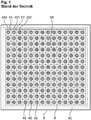
- an antigen chip AC known from the prior art with antigen spots AS for a recorded image area B for a first color channel or first dye is shown as an example.
- a grid R to be generated or recognized is also shown.
- the chip AC carries a spot pattern SM. It is assumed that the antigen spot ASX carries a different antigen than the antigen spot ASY. The left, upper antigen spot ASX must therefore be in the upper left field FX of the grid, so that an assignment to a specific antigen can be made correctly.
- the Fig. 2 shows a configuration in which there was no exact or no exact local arrangement of the spots AS on the substrate of the chip AC.
- the spot ASX is therefore only partially present on the chip AC and in the image area B, so that the raster R per se could be detected, but the fields FX, FY can be misaligned with respect to the spots ASX, ASY.
- An assignment of an antigen type to the spot ASY on the basis of the grid field FX assigned to the spot ASY would therefore be faulty and then also a binding detection with regard to the binding of antibodies of the biological sample to a specific antigen.
- a method according to the invention for the automated detection of antibodies in a liquid biological sample using an antigen chip and a corresponding antigen chip according to the invention are therefore proposed.
- the antigen chip according to the invention has a flat substrate surface with antigen spots which are spaced apart from one another and have the same, common dye.
- This dye can also be referred to as a first dye.
- the antigen spots here form respective antigen spot amounts, which form respective, regular antigen spot patterns, antigen spots of the same antigen spot amount having the same, common type of antigen.
- two or more of the antigen spot amounts have different antigen types.
- the antigen chip according to the invention is characterized in that reference spots are also applied to the substrate surface, which also have the same, common dye.
- the reference spots form a reference spot quantity, which in turn forms a regular reference pattern, in particular along an arrangement direction in which the patterns follow one another.
- the regularity of the reference pattern differs from the antigen spot patterns or from the regularities of the antigen spot patterns.
- the antigen chip according to the invention is then used in the method according to the invention for the automated detection of antibodies in a liquid biological sample.
- the same, common dye can also be referred to as a first dye.
- the spots of the antigen chip are first incubated with the biological sample. Furthermore, the spots are incubated with a conjugate which has a secondary antibody labeled with a second dye.
- the bindings of the secondary antibodies and thus also of the second dye described above can result at certain antigen spots, depending on the type of antigen of an antigen spot and depending on the primary antibody contained in the sample.
- first image information is then acquired or provided, which represents a coloring of the reference spots and the antigen spots by the first dye.
- the reference pattern and a reference position associated with the reference pattern are then detected on the basis of the at least first image information. Furthermore, on the basis of the at least one first piece of image information, the respective antigen spot patterns and the respective associated further positions are then detected. Furthermore, on the basis of the detected reference position and the detected further positions, assignment information is created which indicates an assignment of the respective antigen spot patterns to respective antigen types. Finally, second image information is captured or provided, which represents a potential coloring of the antigen spots by the second dye. Finally, on the basis of the second image information and the assignment information, a determination of the respective binding measures is carried out, which indicate the respective binding of antibodies of the biological sample to the respective antigen types.
- the reference pattern and the antigen pattern are arranged along a direction of arrangement of the patterns, furthermore in particular the reference pattern and the antigen pattern have respective directions of propagation which are essentially perpendicular to the direction of arrangement of the patterns.
- the reference pattern and the antigen spot patterns preferably have respective directions of propagation which run perpendicular to an arrangement direction of the patterns.
- the directions of propagation of the patterns preferably run essentially parallel to one another.
- the antigen spots and the reference spots have the same, common dye which is visible in a first color channel, which is preferably a so-called red channel.
- the antigen chip according to the invention and the method according to the invention achieve one or more of the advantages now mentioned below, for which detailed explanations follow below.
- the antigen chip has reference spots, which form their own regular reference pattern, which differs in its regularity from the antigen spot patterns of the antigen spots, it is possible to determine a position or location of the reference Pattern to be detected in the first color channel or the first image information. Since the antigen spot patterns differ in their type of pattern or their regularity from the reference pattern, the antigen spot patterns can be detected separately with regard to their position or position on the substrate surface. It can then be determined which of the antigen spot patterns has which antigen types, since the reference position of the reference pattern in relation to further positions of the further antigen spot patterns indicates from where or from which position trace a sequence of the antigen spot patterns in an arrangement direction of the patterns on the substrate surface.
- a specific antigen spot pattern with a specific type of antigen need not therefore be arranged at a very specific point on the image or on the substrate surface. Rather, it is sufficient that an antigen spot pattern is arranged in a specific position relative to the reference position of the reference pattern along an arrangement direction of the patterns.
- An assignment information item, which indicates an assignment of respective antigen spot patterns to respective antigen types, can then be made, for example, by providing a data record which assigns such an assignment depending on a position of the antigen spot pattern indicates a position of the reference pattern.
- the method according to the invention particularly robust, since it is only necessary to arrange the antigen spots of a specific antigen spot quantity as an antigen spot pattern in such a way that the corresponding pattern is sufficiently different from other patterns, for example, in its position.
- the antigen spots do not form their own regular patterns, but are arranged in a kind of checkerboard process at a wide variety of positions, with an assignment of a specific antigen type to spots being very sensitive to the individual alignment of the spots on the substrate surface or a picture.
- the antigen chip according to the invention is particularly advantageous because, as described above, it is only a matter of the sequence of the reference pattern and the antigen spot patterns in the arrangement direction or along the arrangement direction of the patterns on the substrate surface, so that the reference pattern and the further antigen spot patterns merely in an orderly sequence on one another along the arrangement direction must occur.
- This has particular advantages in the course of a production process, since when the entirety of the patterns is applied in a periodic, repetitive or repetitive manner, so that the entirety of the patterns is repeated periodically one after the other, the substrate carrier is not subsequently separated or exactly at that point. must be fragmented, on which the entirety of the patterns is repeated in order to produce several antigen chips, each with the entirety of the patterns.
- antigen spot quantities or antigen spot patterns and the reference pattern or reference spot quantity each occur at least once on the antigen chip to be produced.
- Such an entirety of the patterns or such a sequence of these antigen spot patterns and the reference pattern usually results over a predetermined distance along the direction of arrangement of the patterns on the substrate carrier.
- this distance does not have to be kept exactly, but it is sufficient if the repetition distance of the entirety of the patterns along the arrangement direction of the patterns during the production of the antigen chip is not only undercut.
- the substrate surface can also be separated or fragmented after a distance along the arrangement direction which is greater than the repetition distance of the entirety of the patterns in the arrangement direction, within which all different patterns are contained at least once.
- the distance between two fragmentation sites is greater than the repetition distance of the entirety of the patterns and furthermore also less than twice the repetition distance of the entirety of the patterns.
- the separation or fragmentation takes place in particular in a direction perpendicular to the direction of arrangement of the patterns.
- the antigen chip according to the invention and the method according to the invention are also advantageous since a slight misalignment of individual spots within a certain pattern is an effect to which the method according to the invention reacts less sensitively than the solution according to the prior art, in which all spots are in one clearly defined and rigid pattern with the same distances between all neighboring spots.
- the antigen chip according to the invention it is just possible that when the patterns are arranged along an arrangement direction in succession on the substrate surface, a spacing of the patterns from one another between different patterns can also be designed differently.
- the patterns in the method according to the invention are recognized or detected, for example, by the fact that the regularity of a pattern consists of the spots of a corresponding spot quantity or of a relevant spot pattern being a certain distance apart on average to each other, a next, adjacent pattern to the previous pattern can have a neighboring distance, which can be different from another neighboring distance between other patterns. Nevertheless, the method according to the invention can still robustly identify corresponding positions of the patterns by image analysis of the antigen chip according to the invention and assign the respective spots to the respective antigen types.
- the regularity of the reference pattern differs from the regularity of the antigen spot pattern in that the pattern, that is to say the reference pattern, as well as the antigen spot Patterns, have a common regularity parameter, the value of which differs in the reference pattern from the values of this regularity parameter of the antigen spot pattern.
- the same common dye is preferably a fluorescent dye, which can also be referred to as the first fluorescent dye.
- the same, common dye is a chromogenic substrate which, for the purpose of chromogenic staining, can bind to an enzyme which in turn is contained in a conjugate, by means of which the spots of the antigen chip can be incubated.
- the second dye is preferably a fluorescent dye, which can be referred to as a second fluorescent dye.
- the respective fluorescent dyes can be excited by irradiating excitation light of respective different excitation wavelengths or the same excitation wavelength to emit respective fluorescent radiation of respective different fluorescence wavelengths.
- the excitation light wavelengths for the two fluorescent dyes can overlap or be identical.
- the antigen chip is preferably characterized in that the same common dye is a fluorescent dye.
- the antigen chip is preferably characterized in that the second dye is a fluorescent dye.
- the antigen chip is characterized in that the reference spots of the reference spot quantity form a reference line pattern and that the respective antigen spots of the respective antigen spot quantities form respective antigen line patterns.
- the distance of the antigen spots from one another within a pattern for at least one of the patterns differs from a spacing distance or neighboring distance of the pattern from an adjacent pattern in the arrangement direction of the patterns.
- the antigen chip is preferably characterized in that the reference spots also have an antigen.
- the antigen chip is preferably characterized in that the reference spots also have an antibody, in particular IgG.
- the binding dimensions are preferably output, in particular in the form of a data element, which is output in particular via a data interface.
- the first image information is preferably received via at least one data interface and is provided by means of at least one storage unit, and the second image information is preferably also received via the data interface and by means of the Storage unit provided.
- the first image information preferably represents a coloring of the reference spots and the antigen spots of the antigen chip by the first fluorescence radiation.
- the second image information preferably represents a potential coloration of the antigen spots of the antigen chip by the first fluorescent radiation.
- the first excitation light and the second excitation light preferably have the same excitation wavelength.
- the device also has at least one illumination unit for emitting excitation light for exciting an emission of first fluorescent radiation of a first wavelength range through the first dyes.
- the device also has at least one illumination unit for emitting excitation light for exciting an emission of second fluorescence radiation of a second wavelength range through the second dye.
- the proposed device for the automated detection of antibodies of a sample preferably has at least one computing unit, which is further configured to carry out further steps which are disclosed above with reference to the method for automated detection of antibodies and / or the method for automated image processing or have been described.
- a data network device for automated image evaluation for detecting antibodies in a sample is also proposed.
- the data network device is preferably a so-called cloud system.
- the data network device has at least one data interface which is designed to receive first image information which represents a coloring of reference spots and of antigen spots of an antigen chip according to the invention according to one of the embodiments proposed here by a first dye.
- the data interface is also designed to receive second image information, which shows a potential coloring of the antigen spots of the antigen chip according to the invention according to one of the embodiments proposed here by a second dye after incubating the antigen chip with the biological sample and with a conjugate which has a secondary antibody labeled with the second dye.
- a data carrier signal that transmits the computer program product is also proposed.
- the data carrier signal can be provided, for example, in the form of data packets, in particular IP packets.
- the data signal is a download data signal for the transmission of software, in particular a software application.
- a slide is also proposed which has a multiplicity of antigen chips according to the invention in accordance with one of the embodiments described here.
- the production method preferably further comprises the step of fragmenting the substrate in order to obtain a plurality of antigen chips, in particular at two fragmentation sites whose spacing from one another is greater than a width of the substrate, within which the entirety of the reference pattern and antigen pattern is present.
- the substrate surface is preferably a surface of a glass substrate or a glass substrate coated with a membrane and / or film.
- the application of the antigen spots can be carried out by means of a piezoelectric microdosing device, and the substrate surface can in particular be a surface of a glass substrate or a glass substrate coated with a membrane and / or film. This means that production can be carried out using conventional basic materials and production machines.
- kits for use in a method for detecting antibodies in a liquid, biological sample which has an antigen chip according to the invention according to one of the embodiments described here, and further a conjugate which has a secondary antibody labeled with a second dye.
- the second dye is preferably a fluorescent dye, a chromogenic substrate, an enzyme or a substrate for a chemiluminescence reaction.
- the chip can be viewed as a solid substrate, such as a glass plate or, for example, silicon plate.
- the chip can also be made of plastic or metal.
- the chip can be translucent or non-translucent to support transmitted light or incident light illumination or detection.
- the antigen chip can be used in a scanner or camera system, in particular a fluorescence microscope, to examine a sample and can then be irradiated with illuminating light or excitation light.
- the substrate surface is microstructured for focusing.
- the microstructuring can be carried out by a surface treatment (for example roughening) and can facilitate focusing on the substrate surface.
- a surface treatment for example roughening
- Various processes for microstructuring such as injection molding, hot stamping or imprint processes, are known in the prior art.
- Various microstructure markers can be applied to the surface, which can also be used to identify the antigen chip, to identify the sample, etc.
- the antigen substrate (the chip) comprises in particular an area with a size between 1 mm x 1 mm and 2 mm x 4 mm.
- chemiluminescence refers to a chemical reaction in which energy is specifically directed to a molecule, causing it to be electronically excited and then to release a photon, thereby emitting visible light. Thermal energy is not required for this reaction. Chemiluminescence therefore involves the direct conversion of chemical energy into light energy. Chemiluminescence is preferably produced by the reaction of a luminophore with other compounds. These reactions can be catalyzed by enzymes. In further preferred embodiments of the invention, the luminophore is selected from the group consisting of luminol and derivatives thereof, acridine and derivatives thereof and luciferins. These compounds can be stimulated to chemiluminescence by various enzymatic reactions.
- the luminophore is luminol or a derivative thereof, light being emitted by a reaction catalyzed by peroxidase, in particular horseradish peroxidase (chemiluminescence).
- the luminophore is Acridine or a derivative thereof, in particular an acridinium ester or acridinium sulfonamide, light being emitted by a reaction catalyzed by phosphatase, in particular alkaline phosphatase (AP) (chemiluminescence).
- the luminophore is a luciferin, in particular D-luciferin, light being emitted by a reaction catalyzed by luciferase (chemiluminescence).
- a "chromogenic substrate”, in the sense of the present invention, is a reagent that can be used to measure enzyme activities.
- the chromogenic substrate is changed by enzymatic activity so that a direct or indirect product of the enzymatic reaction can be quantified (photometrically).
- the chromogenic substrate is e.g. from an oligopeptide to which an azo dye, for example paranitroaniline, is coupled.
- the peptide mimics the interface at which the enzyme under investigation cleaves its physiological substrate.
- the dye is released by the enzyme action.
- the color development can be quantified photometrically and the enzyme activity can be determined using a calibration curve.
- the chromogenic substrate can also be 5-bromo-4-chloro-3-indoxyl phosphate (BCIP) and / or nitro blue tetrazolium chloride (NBT).
- a chromogenic substrate can e.g. be detected colorimetrically.
- the antigens contained in the various antigen spots can be selected and designed to bind antibodies that form as a result of autoimmune diseases, allergies and infectious diseases. In the present test system, this relates in particular to antinuclear and / or extractable antinuclear antibodies from the field of collagenosis.
- the following antigens can be contained in the antigen spots: RNP / Sm, Sm, Scl-70, Rib.P0, Jo-1, SS-A, SS-B, dsDNA, nucleosomes / Chromatin, Cenp-B, RNP A, C, 68kDa, Ro-52, Ku, Histone, DFS70.
- the diagnosable collagenoses can contain at least one of the following forms: SLE (Systemic lupus erythematosus), PM, DM (Myositis), SS (Sjögren's Syndrome), CREST syndrome (limited cutaneous form of systemic sclerosis IcSSc), PSS (progressive systemic sclerosis) , MCTD (mixed connective tissue disease, sharp syndrome), AID (autoimmune induced disease). It can be used to diagnose various diseases.
- antigen chips with spots of different antigen types in a kind of checkerboard pattern.
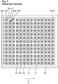
- an antigen chip AC as in FIG Fig. 2 has an alignment of antigen spots AS which does not match a raster to be used later, which is used to assign the spots AS to corresponding antigen types on the basis of their exact position, so that detection of binding of antibodies to a liquid sample certain types of antigen can be carried out by evaluation in a so-called second color channel.
- the Fig. 3a shows an exemplary embodiment of an antigen chip A, in which antigen spots AS in antigen spot patterns AM are applied spaced apart from one another on a substrate surface SO, the antigen spots AS having the same, common dye or first dye.
- the antigen spots form respective antigen spot quantities AG, which in turn form respective regular antigen spot patterns AM.
- the antigen chip A also has a reference pattern RM with reference spots which have a spot distance SD1 from one another.
- the spot distance SD2 of the antigen spots of the antigen spot pattern AM is different from the spot distance SD1 of the reference pattern RM.
- the regularity parameter of the pattern RM, AM is the respective spot distance SD1, SD2 within the respective pattern RM or AM.
- the reference pattern RM thus differs from the antigen spot patterns AM in terms of the value of this regularity parameter or in terms of its regularity.
- the patterns RM, AM are arranged along an arrangement direction ANR.
- the patterns RM, AM each have a direction of propagation ABR which is perpendicular to the direction of arrangement ANR of the patterns AM, RM.
- the spots of the pattern RM, AM have the same, common dye.
- the antigen spots of the antigen spot pattern AM1 have the same, common antigen or a same, common antigen type which differ from an antigen type or an antigen of the pattern AM2.
- an antigen chip A is incubated with all its spots of the pattern RM, AM with a biological sample such as a blood serum, then it can be for the spots of the different antigen spot patterns AM1, AM2 due to the different antigen types of the pattern AM1, AM2 come to differently strong binding of antibodies from the biological, liquid sample to the respective antigen types.
- Such a binding is a so-called first antibody from the biological, liquid sample which is then to be detected later.
- the antigen chip A preferably has a further, second reference pattern RM2, which matches its reference spots with regard to its regularity or its Value of the regularity parameter differs from both the first reference pattern RM and the antigen spot pattern AM. This is the case since the reference pattern RM2 has a spot distance SD3, which clearly differs from the spot distances SD1, SD2.
- the common, identical dye of the spots of the patterns RM, RM2, AM is preferably visible in a first color channel as a red channel.
- the regularity of the reference pattern RM differs from the antigen spot patterns AM and in particular also the second reference pattern RM2 by a variation of a common regularity parameter of the patterns RM, AM and in particular RM2.
- a regularity can also be referred to as a periodicity of a pattern, the regularity parameter being a periodicity parameter. Differing spot patterns then have different values with regard to the same regularity parameter of the spot patterns.
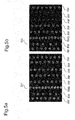
- the 5a and 5b show a first image information BI2 or a second image information BI2 with respective colorations in different color channels by respective dyes.
- the first image information BI1 shows an exemplary reference pattern RM and an exemplary and preferably present second reference pattern RM2 in the first color channel due to a coloring of the first dye. Furthermore, antigen spot patterns AM are visible in the first image information BI1 due to the coloring by the first dye in the first color channel.
- a presumed sequence of antigen types in the arrangement direction ANR with respect to the individual antigen spot patterns AM can be corrected when the in Fig. 3a shown antigen chip A is rotated by 180 °.
- Such an undesired rotation of the antigen chip A can then be detected in image information of the first color channel by the position of the first reference pattern RM and the second reference pattern RM2 relative to one another and thus the position or the position of the antigen spot patterns Correct the assumed arrangement direction ANR even in the event of an undesired 180 ° rotation of the antigen chip.
- the first dye is preferably a fluorescent dye.
- the first dye is a chromogenic substrate which, for the purpose of chromogenic staining, can bind to an enzyme which can be added by a further conjugate in the course of a further incubation of an antigen chip.
- the discoloration due to a binding of the chromogenic substrate with an enzyme it can be regarded as a discoloration product that can be detected photometrically.
- the second image information BI2 from the Fig. 5b shows that a staining in the second color channel is not significantly present for all antigen spot patterns AM due to the second dye. This is presumably the case since there was no significant or significant binding of antibodies of the liquid, biological sample to the corresponding antigen types of the corresponding antigen spot pattern, so that when the antigen chip is incubated with a second conjugate, which contains a second antibody with a label by the second dye, then the second antibodies were not bound to first antibodies from the liquid biological sample.
- the second dye is preferably a fluorescent dye.
- the second fluorescent dye is preferably a chromogenic substrate which can bind to an enzyme, the enzyme being able to be contained in a conjugate which can be used for incubating the spots in a further processing step.
- the enzyme then enters a discoloration product with the chromogenic substrate, which can be detected photometrically.
- the second dye is preferably an enzyme, so that when the spots are incubated with a conjugate which has a chromogenic substrate, the enzyme binds to the chromogenic substrate in order to produce a discoloration product which can be detected photometrically.
- the second dye is preferably an enzyme which can bind or interact in the course of a further processing step by incubating the spots with a conjugate which has a further substrate, so that radiation is emitted due to a chemiluminescence reaction.
- the second dye is preferably a substrate for a chemiluminescence reaction, so that when the spots are incubated with a conjugate which has an enzyme which in turn can react with the substrate, the chemiluminescence reaction will occur, so that chemiluminescence radiation is emitted.
- fluorescent radiation FL can be generated by an excitation light AL1 or AL2, as in FIG Fig. 6 shown to be excited.
- the fluorescent light FL is preferably the light which is emitted by the first fluorescent dye.
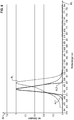
- the axes of the in the representation of the Fig. 6 show the wavelength WL on the abscissa and the intensity IN on the ordinate.
- the axes of the in the representation of the Fig. 7 show the wavelength WL on the abscissa and the intensity IN on the ordinate.
- the Fig. 7 shows in a diagram with a wavelength WL on the abscissa and an intensity IN on the ordinate a spectrum of an excitation light AL, a spectrum FL1 of a first fluorescent radiation by a first fluorescent dye and a spectrum FL2 of a second fluorescent radiation by a second fluorescent dye.
- the first fluorescence FL1 can comprise emission of light in a first wavelength range and the second fluorescence FL2 can comprise emission of light in a second wavelength range, the first wavelength range and the second wavelength range having only a slight or essentially no overlap range, for example an overlap range or an overlap which, for example, corresponds to less than 10%, in particular less than 5%, of an integral of an emission of the first fluorescence over the wavelength.
- the first fluorescent dye can fluoresce, for example, in a red wavelength range, for example in a range between 550 nm and about 800 nm with a maximum between 600 nm and 660 nm.
- the first fluorescent dye can be the dye DY521XL.
- the excitation of the first fluorescent dye can take place in a frequency range, for example between 450 nm and 500 nm, with a maximum, for example between 550 nm and 580 nm.
- the excitation of the second fluorescent dye can take place essentially in the same wavelength range as the excitation of the first fluorescent dye.
- the second fluorescent dye can fluoresce, for example, in a green wavelength range, for example in a range between 500 nm and about 600 nm with a maximum between 510 nm and 530 nm.
- the first fluorescent dye can be the dye FITC.
- a single illuminating light source is required to generate the excitation light, which can be designed in a relatively narrow band.
- the reference spots of the reference spot amount RM can have the dye in a dye concentration which is greater than the dye concentrations in which the antigen spots or the antigen spot quantities or antigen spot pattern AM and in particular also the reference pattern RM2 have the first dye or the same common dye.
- the second reference pattern RM2 can also preferably have this same, common dye in a dye concentration which is greater than the dye concentrations in which the antigen spots of the antigen spot amounts AM have the same, common dye.
- the spots of the reference spot amount RM - and in particular also of the second reference spot amount RM2 - had the same, common dye in a higher dye concentration, this could enable detection of the reference pattern RM - and in particular also of the rest Reference pattern RM2 - can be facilitated in the course of automated image processing, since the color intensities of these spots in image information would be greater than that of the antigen spots of the antigen spot amounts.
- the reference pattern RM forms a reference line pattern and that furthermore the antigen spot patterns AM also form reference line patterns, the lines of the patterns RM and AM having the same direction of propagation.
- the reference pattern RM2 likewise forms a reference line pattern. This can also be referred to as a further or second reference line pattern.
- the respectively associated spots of these patterns follow one another essentially at regular, preferably essentially equidistant intervals, the regular, preferably essentially equidistant, distance of the reference spots of the reference line pattern RM from the regular, preferably essentially equidistant distances of the antigen spots of the antigen line pattern AM differs.
- this pattern RM2 differs both from the first reference pattern RM and from the antigen line patterns AM in that the associated spots of the pattern RM2 differ distinguish their regular, preferably substantially equidistant, distance from the regular, preferably essentially equidistant, distances of the antigen spots of the antigen line pattern AM and of the spots of the first reference pattern RM2.
- the Fig. 3b shows a preferred variant A2 of an antigen chip A2 according to the invention, in which only three antigen spot patterns AM1, AM2, AM3 are present on the antigen chip A2. This is a subset of patterns that are already in this arrangement on the antigen chip A from the Fig. 3a available.
- the patterns RM, RM2, AM are arranged in an arrangement direction ANR.
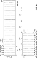
- the Fig. 4a shows a substrate or a substrate surface SU.
- the substrate surface SU is preferably a surface of a glass substrate or a glass substrate coated with a membrane and / or film.
- Different patterns RM, RM2, AM are to be applied to the substrate on the substrate SU along an arrangement direction ANR.
- the spots of the respective patterns RM, RM2, AM are applied to the substrate SU by means of respective pipettes P.
- the pipettes P can in this case be stationary, so that the respective droplets T, the pipettes P apply respective spots for a respective spot quantity, preferably as a line pattern, to the substrate surface SU, the substrate SU thus facing the pipettes P in a feed direction VR1 can be postponed that the aforementioned regular patterns develop.
- the reference spots of the reference spot quantity RM thus form a reference line pattern and the antigen spots of the respective antigen spot quantities AM form respective antigen line patterns.
- a new set of corresponding reference patterns RM, RM2 and antigen spot patterns AM can then be formed by displacing or advancing the substrate support SU in the feed direction VR2 by the distance DI1, in which case the substrate carrier SU is in turn also advanced in the feed direction VR1 in order to bring about a relative movement of the substrate carrier SU with respect to the pipettes P.
- the corresponding pipettes P In order to form the corresponding line patterns RM, RM2, AM with different regular intervals of their respective spots, the corresponding pipettes P only have to be activated in such a way that the drops T are formed with different frequencies or different intervals along the feed direction VR1 , Forming the patterns RM, RM2, AM as a line pattern allows a particularly effective production of the antigen chip according to the invention. Patterns for several antigen chips can then be produced in serial processing on the substrate carrier SU and so a separate substrate carrier SU does not have to be used for each antigen chip.
- the application by the pipette heads is carried out in particular by a so-called piezo pressure using a piezoelectric microdosing device as a special embodiment of the pipettes P. It can thus be stated that application of reference spots and antigen spots to the flat substrate surface SU in this way is carried out that an antigen chip results according to the previously described embodiment.
- the Fig. 4b now illustrates a particular advantage of the antigen chip according to the invention.
- the substrate surface from the Fig. 4a could be fragmented exactly in such a way that the substrate SU is always fragmented exactly according to the distance DI1 parallel to the direction of propagation of the patterns, that is to say perpendicular to the arrangement direction ANR of the patterns.
- a position of the reference pattern RM and the antigen spot pattern AM on the different antigen chips to be produced in this way would then always result in the same, repeating position or position on the corresponding antigen chip. Due to the inventive design of the antigen spot pattern AM and the reference pattern RM and in particular the second reference pattern RM2, however, as in FIG Fig.
- the distance DI2 which can only be selected approximately, so that corresponding antigen chips A11 and A12 result from the Fig. 4b can result. It is essential that the distance DI2, after which the substrate carrier SU is fragmented, is at least as large as the distance DI1 or larger than this distance DI1.
- the distance DI2 to be selected also only has to be less than twice the distance DI1 in order to avoid a complete repetition of all the patterns AM, RM, RM2.
- the sequence of the corresponding antigen types can be compared to the antigen spot patterns AM1, AM2, AM3 due to the distinguishability of these patterns the reference pattern RM and in particular the reference pattern RM2 are used in the course of an automated image evaluation in order to detect binding of antibodies for at least each antigen type or each of the antigen spot patterns AM1, AM2, AM3.
- the subsequently produced antigen chip A12 then has at least each type of an antigen spot pattern AM1, AM2, by choosing the fragmentation distance DI2 versus the repetition distance DI1 of the antigen spot pattern and the reference pattern and in particular the second reference pattern.
- the reference spots RM of the reference pattern can also also preferably still have an antigen, so that binding of antibodies of the biological sample, to which in turn second antibodies of a conjugate can be bound by labeling with a second dye, can then be detected and thus a further, additional type of antigen can be used with regard to detection of antibodies in the biological sample.
- the reference spots of the reference pattern RM and, in particular, of the reference pattern RM2 preferably have antibodies, in particular in the form of anti-human IgG.
- Such an antibody can then bind to an antibody of a liquid patient sample, for example a blood serum, so that after further incubation of the reference spots with a conjugate, which in turn can have a second antibody labeled with a second dye, binding of the second Dye is given to the reference spots.
- a conjugate which in turn can have a second antibody labeled with a second dye
- binding of the second Dye is given to the reference spots.
- the reference spots RM, RM2 can thus be used as an incubation control.
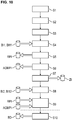
- Fig. 13 shows again steps of the proposed manufacturing process.
- step S100 a substrate with a flat substrate surface is provided.
- step S101 reference spots are applied to the flat substrate surface.
- step S102 antigen spots are applied to the flat substrate surface.
- the antigen spots and the reference spots are applied in order to obtain an antigen chip according to one embodiment in FIG previously described manner.
- step S103 which is preferably to be carried out, the substrate is fragmented in order to obtain a plurality of antigen chips. The fragmentation is carried out while maintaining a distance between two fragmentation sites, which is at least as great as a distance in a repetitive sequence of antigen spot patterns and reference spot patterns, which describes this repetitive sequence in an arrangement direction of the patterns.
- the Figure 18 a slide OT, which has several antigen chips A in different fields FE.
- Fig. 19 shows a detailed representation of a single field FE with several antigen chips A.
- the antigen spot pattern AM and the reference pattern RM can differ in that they have a different periodicity or a different regular spacing of antigen spots from one another.
- This formation of the antigen spot pattern AM and the reference pattern RM is illustrated here in this manner only by way of example.
- the differentiation of the reference pattern RM, in particular also the second reference pattern RM2, from the antigen spot patterns AM consists in the fact that the reference pattern RM along the arrangement direction ANR has such an immediate neighbor to a next immediately adjacent pattern. Has a distance that differs from the other neighboring distances of the antigen spot pattern AM.
- the patterns RM, AM need not have different regular distances between their respective spots within the patterns RM, AM, but can differ based on a distance or a neighboring distance to the next pattern in or along the arrangement direction ANR.
- the reference pattern RM and in particular also the second reference pattern RM2
- the size of the spots of the reference pattern RM differing from the sizes of the antigen Spots of the antigen spot pattern AM differs.
- the reference pattern RM and the antigen spot pattern AM can differ in that spots of different sizes are formed for the different respective patterns RM, AM, which in the course of a manufacturing process, as in FIG Fig. 4a illustrated, for example by different pipette sizes to generate different ones Sizes of spots or different sizes of drops can be used to form the spots.
- the Fig. 10 shows preferred steps of a method according to the invention for the automated detection of antibodies in a liquid biological sample.
- step S1 an antigen chip is provided according to one of the previously described embodiments.
- the spots of the antigen chip are incubated with the biological sample.
- the spots are incubated with a conjugate which has a secondary antibody labeled with a second dye.
- the first piece of image information BI1, BI11 is provided or recorded, which represents a coloring of reference spots and of antigen spots of the antigen chip by a first dye.
- the antigen chip is preferably illuminated in step S4 with a first excitation light of a first wavelength to excite an emission of first fluorescent radiation by the first dye.
- the first image information then represents a coloring of the reference spots and the antigen spots of the antigen chip by the first fluorescence radiation. This is preferably done in a so-called red channel.
- a step S5 the reference pattern and an associated reference position on the substrate surface are detected assuming an arrangement direction of the patterns on the substrate surface on the basis of the at least first image information.
- the reference position can be provided as reference position information RPI.
- a step S6 the respective antigen spot patterns and the respective associated further positions on the substrate surface are detected assuming an arrangement direction of the patterns on the substrate surface on the basis of the at least first image information. This can be provided as so-called further, total position information AGMPI in relation to the further positions of the antigen spot patterns.
- an assignment information item ZI is then created on the basis of the detected reference position and the detected further positions, which indicates an assignment of the respective antigen spot patterns to the respective antigen types.
- second image information BI2, BI12 is then acquired, which provides a potential coloration of the antigen spots and preferably the reference spots are also represented by the second dye.
- the antigen chip is preferably illuminated with a second excitation light of a second wavelength in order to excite an emission of second fluorescent radiation.
- the second excitation light of the second wavelength is preferably identical in its wavelength range to the wavelength range of the first excitation light for exciting the first fluorescent radiation of the first fluorescent dye.
- the second image information then preferably represents a potential coloring of the antigen spots of the antigen chip by the second fluorescent radiation.
- a step S9 preferably using the reference position information RPI and the further position information AGMPI, it is then possible to determine the respective binding measures, which respective bonds or degrees of binding of antibodies of the biological sample to the respective antigen type medicine, on the basis of the second Image information BI2, BI12 and the assignment information ZI take place.
- binding measures can preferably be output in a method step S10, preferably in the form of a data element BD via a data interface.
- Steps S4 to S9 can preferably be carried out in the method according to the invention for automated image processing for detecting antibodies in a liquid biological sample according to one embodiment.
- step S10 which is preferably to be carried out.
- step S10 information is therefore preferably provided via a data interface, which indicates the position of the pattern and preferably also the position of individual antigen spots and individual reference spots on the antigen chip.
- step S7 The assignment of antigen spot patterns to respective antigen types in step S7 is preferably carried out in a manner as in FIG Fig. 11b illustrated.
- a spatial sequence of the reference position of the reference pattern and the respective further positions of the respective further antigen spot patterns is determined. This position can also be referred to as positions along an, in particular assumed, arrangement direction of the patterns on the substrate surface.
- a sequence data record ADS is provided, which indicates a sequence of antigen types.
- this is a spatial sequence of antigen types along an arrangement direction of patterns.
- the Fig. 11c illustrates an exemplary sequence data record ADS, which indicates corresponding antigen types AT1, AT2, AT3 in corresponding fields AT for a sequence of patterns along an arrangement direction ANR for successive positions in corresponding fields PN.
- the sequence data record ADS thus indicates a spatial sequence of respective antigen types for respective positions along an arrangement direction ANR of spot patterns.
- Corresponding reference pattern types R1, R2 are also specified in corresponding fields RT for specific positions. In this preferred embodiment, a first and a second reference pattern are present. It is understood by the person skilled in the art that only one reference pattern type R1 is present in the case of only one reference pattern.
- An assignment information item ZI is then created, which indicates the assignment of the respective antigen spot patterns to the respective antigen types. This is done on the basis of the detected reference position, the detected respective further position of the respective antigen spot pattern and the sequence data record ADS.
- a further reference position of a second reference pattern is preferably also detected in the course of the method and taken into account in the course of the assignment of the respective antigen spot patterns to the respective antigen types. This enables compensation or consideration of an undesired 180 ° rotation of the antigen chip.
- step S5A the second reference pattern and an associated second reference position are then detected in step S5A on the basis of the first image information.
- step S6 described above then follows.
- step S7A the assignment information ZI is then created, which indicates the assignment of the respective antigen spot patterns to the respective antigen types. This is done on the basis of the detected first reference position, the detected second reference position and the detected further position of the respective antigen spot pattern and preferably also of the sequence data set.
- the 20a shows a first reference pattern RM, a second reference pattern RM2 and antigen spot pattern AM represented by first image information BI11 in a first color channel, which is preferably a red channel.
- the Fig. 20b shows in the first image information BI11 corresponding exemplary antigen spot positions AGSPI1, which are shown as rectangles.
- AGSPI1 exemplary antigen spot positions
- RM, RM2 from the 20a the individual spots can then be assigned to individual patterns AM, RM, RM2, in particular line patterns.
- respective positions along the arrangement direction ANR can be determined for respective patterns AM, RM, RM2.
- individual antigen spot patterns can be assigned to individual antigen types, preferably on the basis of a sequence data set.
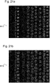
- the Fig. 21a shows a coloring of spots by a second dye of the same antigen chip as from the 20a and 20b .
- the Fig. 21a shows a second image information BI12, which represents a coloring of spots, in particular the antigen spots by the second dye and thus in a second color channel, preferably a green channel.
- a number of potential patterns are then identified on the basis of the at least first image information.
- a respective regular average spot spacing of spots is then detected within a respectively recognized pattern for the respectively recognized, potential pattern.
- one of the recognized patterns is then selected as the reference pattern on the basis of the detected mean spot distances. As can be seen by a person skilled in the art, this can also be carried out for the second reference pattern.
- Fig. 15 preferably steps to be performed.
- a step S30 circular objects are identified in the first image BI11 by means of a Hough transformation.
- step S31 extraction of properties for the identified circular objects, such as e.g. a contour and / or intensity properties.
- the properties can be a circumference of a circle, a deviation from a perfect free circle or the average intensity of an object.
- a step S32 the proposed circular objects from the Hough transformation with their properties are then classified into a first class "spot” or a second class "image artifact” using a support vector machine. Only those image areas or objects that are classified as spots are used below.
- a position on the antigen chip or in the image information BI11 in the X or Y position can be determined or determined in step S31.
- spots can then be combined to form a pattern or a line pattern or a line.
- a list is created for the spots, which is sorted on the basis of their Y position in the image.
- a spot is taken from the list and its closest neighbor is found at a Euclidean distance. If both spots are at an angle of approximately 90 ° to one another or form a straight line which forms an angle of 90 ° with respect to the arrangement direction, it is assumed that they belong to the same pattern or the same line.
- This value of 90 ° can also be provided with a blur window of several plus-minus degrees. If the two spots in question do not belong to each other to a pattern or to such a straight line of approx. 90 ° to the arrangement direction of the patterns, the next spot sorted by distance or Y position is considered from the list. If it is no longer possible to assign spots from the list to the currently viewed pattern or the currently viewed line, a new pattern or a new line is started in a direction perpendicular to the arrangement direction of the patterns. With such a method, the spots are then iteratively assigned to respective patterns or respective lines.
- the patterns or line patterns are then numbered in a step S34. This is preferably done in such a way that the pattern or the line whose spots are at the greatest mean distance from one another are adopted as the reference pattern or as the reference line pattern.
- a second reference pattern is preferably adopted as that pattern or as the line in which the spots have the smallest mean distance from one another.
- BI12 can then be made on the basis of the second image information Fig. 21b for those spots which are assigned to a pattern or a line, the respective intensities or pixel intensities per spot in the second color channel are determined on the basis of a coloring by the second dye. This is preferably done as the median value of the intensities of a spot.
- a determination of an average intensity value of a pattern can be carried out in such a way that the median value of the median intensities of the spots of a pattern is determined. This median value is then a measure of binding, which indicates a binding or a degree of binding of antibodies from the biological sample to a specific type of antigen.
- the antigen spot position information AGSPI obtained previously from step S6 based on the first image information BI11 and the reference spots obtained in step S5 can be used to determine the binding dimensions on the basis of the second image information BI12 - Position information used as in the RSPI Fig. 16 shown.
- the detection of a reference spot pattern and the respective antigen spot pattern thus includes detection of individual spot positions and an assignment of spots or spot positions to the reference pattern and the respective antigen spot pattern.
- a threshold value provided via a data element which can be applied to the median intensity determined for a pattern or an antigen type, is preferably used to determine a binding measure. If the median intensity value of a pattern falls below the threshold value, it is assumed that there is no binding of antibodies at all. Only in the event that the median value of a pattern exceeds the predefined threshold value is a value output which indicates that there is binding of antibodies to the corresponding antigen types.
- the binding dimensions can be output via a data element, for which, as in Fig. 12 drawn in, a data record BD indicates an assignment of binding measures BM to corresponding antigen types AT.
- the data record BD can be a list, for example.
- a binding measure BM1 is then included for an antigen type AT1, and corresponding binding measures BM2, BM3 for corresponding antigen types AT2, AT3.
- the reference pattern to an immediately adjacent pattern along the arrangement direction of the patterns has such a neighboring distance that differs from the other neighboring distances of the antigen spot pattern.
- the Fig. 22a an embodiment A21, at which only has a reference pattern RM.
- the reference pattern RM has a neighboring distance DI11 to the next directly adjacent pattern AM1 in the arrangement direction ANR, which is greater than the neighboring distance DI12 of the other patterns AM1, AM2, AM3 to their closest neighboring ones in the arrangement direction ANR Patterns AM2, AM3, RM.
- detected spot positions of the reference spots and the antigen spots can be used, as previously described in detail, to assign the spots to respective patterns or line patterns, so that just a few patterns based on the first Image information BI11 can be recognized.
- respective neighboring distances DI11, DI12 between the patterns can then be determined, that is, for example, a neighbor distance for the reference pattern to the directly adjacent next pattern to the right of it in the direction of the arrangement direction ANR. If the reference pattern has a neighboring distance that differs from the neighboring distances of the antigen spot patterns, the referring pattern can be reliably detected and recognized.
- the respective associated spots have a respective, identical size, the size of the reference spots of the reference pattern being different Sizes of the antigen spots differ from the antigen spot patterns.
- Fig. 22b a preferred embodiment A22 of an antigen chip in which there is only one reference pattern RM.
- the reference spots of the reference pattern RM have the same size. This size differs of the same common size that the antigen spots of the antigen pattern AM have.
- the Fig. 8 shows a device V1 according to the invention according to an embodiment for the automated detection of antibodies in a sample.
- the device V1 comprises a so-called microscope device.
- An antigen chip C can be viewed through a lens O by means of at least one camera K1, K2.
- the cameras K1, K2 can be referred to as image acquisition units.
- the structure from the Fig. 8 for the device V1 an explicit separation of two color channels or optical channels is provided before image information is acquired by separate image acquisition units K1, K2. It is obvious to the person skilled in the art that such a device can also be realized by exchanging optical filters over time, in that only a single image acquisition unit is provided, but the use of the different optical filters for different color channels means that the device was previously described respective image information that can be captured in the respective color channels.
- a fluorescence light source LQ emits an excitation light AL, which is filtered by means of an excitation light filter F1 so that an in Fig. 7 described excitation light spectrum AL is directed to the dichroic mirror SP1.
- the dichroic mirror SP1 then directs this excitation light AL towards the objective O, through which the excitation light then strikes the antigen chip C and its spots.
- the first and second fluorescent radiation emitted by the antigen chip C or the fluorescent dyes of the spots then pass through the objective O through the dichroic mirror SP1 to an optical filter F2 which blocks the excitation light AL or its spectrum and the fluorescent radiation of the first Color channel and also a second color channel transmitted.
- the fluorescence radiation then arrives at a further dichroic mirror SP2, which reflects fluorescence radiation from the first color channel or first fluorescence radiation to a first image acquisition unit or camera K1.
- the first fluorescence radiation from the incoming spectrum is preferably also filtered by an optical filter FR.
- the filter FR is in particular a red channel filter.
- the dichroic mirror SP2 transmits the second fluorescent radiation or light of the second color channel to a second image acquisition unit or camera K2.
- This radiation is preferably filtered again by a further optical filter FG, the optical filter FG being in particular a green channel filter.
- the first camera K1 then captures the first image information BI1 and makes it available to the computing unit R.
- the second image capture unit K2 then captures the second image information BI2 and makes it available to the computing unit R2.
- the first image acquisition unit and the second image acquisition unit as an example for at least one image acquisition unit are then designed to acquire first image information BI1, which is a coloring of reference spots and of antigen spots of an antigen chip C by a first dye, in particular a first dye Fluorescent dye.
- the at least one image capture unit K1, K2 is designed to capture second image information BI2, which shows a potential coloring of the antigen spots of the antigen chip by a second dye, in particular a second fluorescent dye, after incubation of the antigen chip with the biological sample and with a conjugate which has a secondary antibody labeled with the second dye.
- the computing unit R is in particular designed to carry out one or more of the steps S4, S5, S6, S7 and S9 described previously with reference to the method for the automated detection of antibodies and the method of automated image processing for the detection of antibodies Fig. 10 perform.
- the computing unit R controls the image acquisition units K1, K2 and the fluorescent light source LQ accordingly.
- the device V1 from in Fig. 8 also preferably has a data interface DS1, via which data elements DA can be received or sent.
- binding measures can be transmitted here via such data elements DA, and data elements which indicate a threshold value can also preferably be received.
- the device V1 thus has, with the fluorescent light source LQ, an illumination unit for emitting excitation light for exciting an emission of first fluorescent radiation of a first wavelength range by the first dyes. Furthermore, the light source LQ also represents at least one illumination unit for emitting excitation light for exciting an emission of second fluorescent radiation of a second wavelength range by the second dye.
- Fig. 17 shows preferred steps in the course of the described method for automated detection of antibodies and / or the method for automated image processing.
- BI12 takes place in the second color channel or the second image information Fig. 21a or 21b an identification of antigen spots using the antigen spot position information AGSPI or the further position information AGMPI. Furthermore, in the case that the reference spots also have an antigen, the reference position information is used RPI or the reference spot position information RSPI an identification of the reference spots.
- image areas or spots are assigned to specific patterns and thus also to specific antigen types in step S41.
- a step S42 an average intensity or median intensity of a pattern is determined in the second color channel or on the basis of the second image information.
- step S43 a data record TH is provided or received, which indicates a threshold value to be applied to median intensities.
- This threshold value is then applied in step S43 to the determined average intensities of the respective patterns.
- a determination of the respective binding dimensions for the respective pattern is then carried out.
- a step S44a which is preferably to be carried out, an indication is then given to the user, preferably by means of an optical display unit or preferably by means of a data element to be output via a data interface, in the event that the reference spots of the reference pattern are in the second color channel or the second image information does not have sufficient coloring or medium intensity.
- the binding dimensions are then output in step S45.
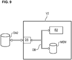
- the Fig. 9 shows an embodiment of a data network device V2 according to the invention, which can preferably also be referred to as a cloud system.
- the data network device V2 for automated image evaluation for the detection of antibodies in a liquid and biological sample has at least one data interface DS, via which data elements DA2 can be exchanged via a data network.
- the device V2 has at least one computing unit R2, which is preferably connected to the data interface DS via a data bus DB.
- the data network device V2 preferably has at least one memory unit MEM.
- the at least one data interface DS is designed to receive first image information that represents a coloring of reference spots and of antigen spots of an antigen chip by a first dye.
- the at least one data interface DS is also designed to receive a second image information which shows a potential coloring of the antigen spots of the antigen chip by a second dye after incubation of the antigen chip with the biological sample and a conjugate which is one with the second dye has labeled secondary antibodies.
- the computing unit R2 is designed to carry out the steps described above with reference to the method for automated image processing, in particular one or more of the steps S4, S5, S6, S7 and S9. Furthermore, the computing unit R2 is designed to carry out further steps of the method for automated image processing which are preferably to be carried out and which have been explained in detail above.
- the device V2 from the Fig. 9 is furthermore preferably designed to provide data elements DA2 via the data interface DS which represent information which indicates the respective binding measures of antibodies to the respective antigen types.
- the data interface DS is also designed to index positions of antigen spots and / or patterns and reference spots or reference patterns detected via data elements.
- the device V2 from the Fig. 9 automated image processing for detecting antibodies in a liquid biological sample takes place, in particular, in that the first image information is received via the at least one data interface DS and is provided by means of the at least one memory unit MEM, the second image information also being received via the data interface DS is and is also provided by means of the memory unit MEM.
- the device V2 is preferably designed to receive a data element via the data interface DS which indicates certain types of antigen to which binding measures are to be output. An evaluation is then preferably carried out for these specific antigen types indicated and also a transmission of a data element which indicates the binding measures of the corresponding specific antigen types.
- aspects have been described in connection with a device, it goes without saying that these aspects also represent a description of the corresponding methods, so that a block or a component of a device can also be understood as a corresponding method step or as a feature of a method step. Analogously, aspects that have been described in connection with or as a method step also represent a description of a corresponding block or details or feature of a corresponding device.
- exemplary embodiments of the invention can implement the computing units R, R2 in hardware and / or in software.
- a processing unit R, R2 mentioned here can be implemented here as at least one processing unit or else by a plurality of processing units in the network.
- the implementation can be carried out using a digital storage medium such as a floppy disk, DVD, Blu-Ray disc, CD, ROM, PROM, EPROM, EEPROM or FLASH memory, hard disk or other magnetic or optical memory are carried out, on which electronically readable control signals are stored, which can interact with a programmable hardware component or cooperate in such a way that the respective method is carried out.
- CPU Central Processing Unit
- ASIC Application-Specific Integrated Circuit
- IC Integrated Circuit
- SOC System on Chip
- FPGA Field Programmable Gate Array
- the digital storage medium can therefore be machine or computer readable.
- Some exemplary embodiments thus comprise a data carrier which has electronically readable control signals which are able to interact with a programmable computer system or a programmable hardware component in such a way that one of the methods described herein is carried out
- exemplary embodiments or parts of the exemplary embodiments of the present invention can be used as a program, firmware, computer program or Computer program product can be implemented with a program code or as data, wherein the program code or the data is or are effective to perform one of the methods or a part of a method if the program runs on a processor or a programmable hardware component.
Abstract
Vorgeschlagen wird ein Verfahren zum automatisierten Detektieren von Antikörpern in einer flüssigen biologischen Probe mittels Verwendung eines Antigen-Chips mit darauf aufgebrachten Antigen-Spots, welche einen gleichen, gemeinsamen Farbstoff aufweisen. Die Antigen-Spots bilden jeweilige Antigen-Spot-Mengen aus, welche korrespondierende jeweilige, regelmäßige Antigen-Spot-Muster ausbilden. Ferner sind Referenz-Spots mit dem gleichen Farbstoff aufgebracht sind, welche eine Referenz-Spot-Menge ausbilden, welche ein regelmäßiges Referenz-Muster ausbildet. Das Referenz-Muster unterscheidet sich von den Antigen-Spot-Mustern hinsichtlich seiner Regelmäßigkeit. Auf Basis einer ersten Bildinformation, welche eine Färbung der Referenz-Spots und der Antigen-Spots durch den gleichen, ersten Farbstoff repräsentiert, und auf Basis einer zweiten Bildinformation, welche eine potentielle Färbung der Antigen-Spots durch einen zweiten Farbstoff nach einer Inkubation repräsentiert wird dann mittels Bildverarbeitung eine Bindung von Antikörpern der biologischen Probe an jeweilige Antigen-Typen bestimmt.A method is proposed for the automated detection of antibodies in a liquid biological sample using an antigen chip with antigen spots applied thereon which have the same, common dye. The antigen spots form respective antigen spot quantities, which form corresponding respective regular antigen spot patterns. Furthermore, reference spots are applied with the same dye, which form a reference spot quantity, which forms a regular reference pattern. The reference pattern differs from the antigen spot patterns in terms of its regularity. On the basis of a first image information, which represents a coloring of the reference spots and the antigen spots by the same, first dye, and on the basis of a second image information, which represents a potential coloring of the antigen spots by a second dye after an incubation then a binding of antibodies of the biological sample to respective antigen types is determined by means of image processing.
Description
Die Erfindung betrifft ein Verfahren zum automatisierten Detektieren von Antikörpern in einer flüssigen biologischen Probe mittels Verwendung eines Antigen-Chips sowie einen entsprechenden Antigen-Chip hierfür.The invention relates to a method for the automated detection of antibodies in a liquid biological sample using an antigen chip and a corresponding antigen chip therefor.
Die Erfindung betrifft ferner ein Verfahren für eine automatisierte Bildverarbeitung zum Detektieren von Antikörpern in einer flüssigen biologischen Probe.The invention further relates to a method for automated image processing for the detection of antibodies in a liquid biological sample.
Die Erfindung betrifft ferner eine Vorrichtung für eine automatisierte Bildverarbeitung zum Detektieren von Antikörpern in einer flüssigen biologischen Probe.The invention further relates to a device for automated image processing for detecting antibodies in a liquid biological sample.
Die Erfindung betrifft ferner eine Datennetzwerkvorrichtung für eine automatisierte Bildverarbeitung zum Detektieren von Antikörpern in einer flüssigen biologischen Probe.The invention further relates to a data network device for automated image processing for detecting antibodies in a liquid biological sample.
Die Erfindung betrifft ferner ein Computerprogrammprodukt, welche Befehle umfasst, die bei der Ausführung des Programms durch einen Computer diesen veranlassen, ein Verfahren für eine automatisierten Bildverarbeitung zum Detektieren von Antikörpern in einer flüssigen biologischen Probe.The invention further relates to a computer program product which comprises commands which cause the computer to execute the program, a method for automated image processing for the detection of antibodies in a liquid biological sample.
Die Erfindung betrifft ferner ein Datenträgersignal, das das Computerprogrammprodukt überträgt.The invention further relates to a data carrier signal that transmits the computer program product.
Die Erfindung betrifft ferner ein Verfahren zum Herstellen eines Antigen-Chips.The invention further relates to a method for producing an antigen chip.
Die Erfindung betrifft ferner einen Objektträger mit einer Mehrzahl von Antigen-Chips.The invention further relates to a slide with a plurality of antigen chips.
Die Erfindung betrifft ferner ein Kit zur Verwendung in einem Verfahren zum Detektieren von Antikörpern in einer Probe, aufweisend wenigstens einen Antigen-Chip.The invention further relates to a kit for use in a method for detecting antibodies in a sample, comprising at least one antigen chip.
Im Sinne dieser Anmeldung kann eine flüssige, biologische Probe auch als eine flüssige Patientenprobe eines Patienten bezeichnet werden. Ein Beispiel für eine flüssige Patientenprobe ist eine flüssige Patientenprobe, welche Blutsbestandteile aufweist. Insbesondere kann die flüssige Patientenprobe ein Blutserum sein.For the purposes of this application, a liquid, biological sample can also be referred to as a liquid patient sample from a patient. An example of a liquid patient sample is a liquid patient sample that has blood components. In particular, the liquid patient sample can be a blood serum.
Bekannt sind diagnostische Verfahren, bei welchen mittels Antigenen ein Vorhandensein von Antikörpern in einer flüssigen biologischen Probe wie z.B. Blutserum detektiert wird. Hierzu werden Substrate, auch Chips genannt, verwendet, auf deren Oberfläche Antigene in Form von Geltropfen bzw. Spots aufgebracht werden. Die Tropfen bzw. Spots trocknen nach der Aufbringung an der Oberfläche des Substrates an. Um Nachzuweisen, ob Antikörper eines bestimmten Typs in einer flüssigen biologischen Patientenprobe vorhanden sind, werden die Spots zunächst mit der Probe inkubiert, wobei dann abhängig von dem Typ der Antigene und dem Typ der Antikörper es zu einer Bindung von Antikörpern an Antigene kommen kann. Die Antikörper der Probe werden in einem solchen Verfahren mitunter auch als erste Antikörper bezeichnet. Anschließend erfolgt dann eine Inkubation der Spots mit einem Konjugat, welches zweite Antikörper aufweist, die wiederum mit einem Farbstoff markiert sind. Die zweiten Antikörper binden dann an die ersten Antikörper an, so dass dann mittels eines Nachweises einer Färbung der Spots durch den Farbstoff eine Bindung der ersten Antikörper an die Antigene indirekt nachgewiesen werden kann um Aufschluss darüber zu erhalten, ob erste Antikörper eines bestimmten Typs in der Probe enthalten sind bzw. waren. Der Farbstoff kann hierbei beispielsweise ein Fluoreszenzfarbstoff sein.Diagnostic methods are known in which the presence of antibodies in a liquid biological sample such as blood serum is detected by means of antigens. For this purpose, substrates, also called chips, are used, on the surface of which there are antigens in the form applied by drops of gel or spots. After application, the drops or spots dry on the surface of the substrate. In order to demonstrate whether antibodies of a certain type are present in a liquid biological patient sample, the spots are first incubated with the sample, in which case, depending on the type of antigens and the type of antibodies, antibodies can bind to antigens. In such a method, the antibodies of the sample are sometimes referred to as first antibodies. The spots are then incubated with a conjugate which has second antibodies which are in turn labeled with a dye. The second antibodies then bind to the first antibodies, so that a detection of a coloring of the spots by the dye can then indirectly detect a binding of the first antibodies to the antigens in order to obtain information about whether first antibodies of a certain type in the Sample are or were included. The dye can be, for example, a fluorescent dye.
Bekannt ist es aus dem Stand der Technik, wie z.B. der
In der
Die
Vorgeschlagen wird daher ein erfindungsgemäßes Verfahren zum automatisierten Detektieren von Antikörpern in einer flüssigen biologischen Probe mittels Verwendung eines Antigen-Chips sowie ein entsprechender erfindungsgemäßer Antigen-Chip.A method according to the invention for the automated detection of antibodies in a liquid biological sample using an antigen chip and a corresponding antigen chip according to the invention are therefore proposed.
Der erfindungsgemäße Antigen-Chip weist eine ebene Substratoberfläche mit darauf aufgebrachten, zueinander beabstandeten Antigen-Spots auf, welche einen gleichen, gemeinsamen Farbstoff aufweisen. Dieser Farbstoff kann auch als ein erster Farbstoff bezeichnet werden. Die Antigen-Spots bilden hierbei jeweilige Antigen-Spot-Mengen aus, welche jeweilige, regelmäßige Antigen-Spot-Muster ausbilden, wobei Antigen-Spots einer gleichen Antigen-Spot-Menge einen gleichen, gemeinsamen Antigentyp aufweisen. Hierbei weisen zwei oder mehr der Antigen-Spot-Mengen unterschiedliche Antigen-Typen auf. Der erfindungsgemäße Antigen-Chip ist dadurch gekennzeichnet, dass auf der Substratoberfläche ferner Referenz-Spots aufgebracht sind, welche ebenfalls den gleichen, gemeinsamen Farbstoff aufweisen. Die Referenz-Spots bilden eine Referenz-Spot-Menge aus, die wiederum ein regelmäßiges Referenz-Muster ausbildet, insbesondere entlang einer Anordnungsrichtung, in welcher die Muster aufeinander abfolgen. Das Referenz-Muster unterscheidet sich hinsichtlich seiner Regelmäßigkeit von den Antigen-Spot-Mustern bzw. von den Regelmäßigkeiten der Antigen-Spot-Muster.The antigen chip according to the invention has a flat substrate surface with antigen spots which are spaced apart from one another and have the same, common dye. This dye can also be referred to as a first dye. The antigen spots here form respective antigen spot amounts, which form respective, regular antigen spot patterns, antigen spots of the same antigen spot amount having the same, common type of antigen. Here, two or more of the antigen spot amounts have different antigen types. The antigen chip according to the invention is characterized in that reference spots are also applied to the substrate surface, which also have the same, common dye. The reference spots form a reference spot quantity, which in turn forms a regular reference pattern, in particular along an arrangement direction in which the patterns follow one another. The regularity of the reference pattern differs from the antigen spot patterns or from the regularities of the antigen spot patterns.
Der erfindungsgemäße Antigen-Chip findet dann Anwendung in dem erfindungsgemäßen Verfahren zum automatisierten Detektieren von Antikörpern in einer flüssigen biologischen Probe. Der gleiche, gemeinsame Farbstoff ist hierbei eben auch als ein erster Farbstoff zu bezeichnen. Im Zuge des Verfahrens werden die Spots der Antigen-Chip zunächst mit der biologischen Probe inkubiert. Ferner werden die Spots mit einem Konjugat inkubiert, welches einen mit einem zweiten Farbstoff markierten sekundären Antikörper aufweist. Hierdurch können sich an bestimmten Antigen-Spots die zuvor beschriebenen Bindungen der sekundären Antikörper und somit auch des zweiten Farbstoffs ergeben, abhängig von dem Typ des Antigens eines Antigen-Spots und abhängig von in der Probe enthaltener primärer Antikörper. Im Zuge des Verfahrens wird dann eine erste Bildinformation erfasst oder bereitgestellt, welche eine Färbung der Referenz-Spots und der Antigen-Spots durch den ersten Farbstoff repräsentiert. Auf Basis der wenigstens einen ersten Bildinformation erfolgt dann ein Detektieren des Referenz-Musters sowie einer zu dem Referenz-Muster zugehörigen Referenz-Position. Ferner erfolgt dann auf Basis der wenigstens einen ersten Bildinformation ein Detektieren der jeweiligen Antigen-Spot-Muster sowie jeweiliger zugehöriger weiterer Positionen. Ferner erfolgt auf Basis der detektierten Referenz-Position und der detektierten weiteren Positionen ein Erstellen einer Zuordnungs-Information, welche eine Zuordnung der jeweiligen Antigen-Spot-Muster zu jeweiligen Antigen-Typen indiziert. Schließlich erfolgt ein Erfassen oder Bereitstellen einer zweiten Bildinformation, welche eine potentielle Färbung der Antigen-Spots durch den zweiten Farbstoff repräsentiert. Abschließend erfolgt, auf Basis der zweiten Bildinformation und der Zuordnungs-Information, ein Bestimmen jeweiliger Bindungsmaße, welche jeweilige Bindungen von Antikörpern der biologischen Probe an jeweilige Antigen-Typen indizieren.The antigen chip according to the invention is then used in the method according to the invention for the automated detection of antibodies in a liquid biological sample. The same, common dye can also be referred to as a first dye. In the course of the method, the spots of the antigen chip are first incubated with the biological sample. Furthermore, the spots are incubated with a conjugate which has a secondary antibody labeled with a second dye. As a result, the bindings of the secondary antibodies and thus also of the second dye described above can result at certain antigen spots, depending on the type of antigen of an antigen spot and depending on the primary antibody contained in the sample. In the course of the method, first image information is then acquired or provided, which represents a coloring of the reference spots and the antigen spots by the first dye. The reference pattern and a reference position associated with the reference pattern are then detected on the basis of the at least first image information. Furthermore, on the basis of the at least one first piece of image information, the respective antigen spot patterns and the respective associated further positions are then detected. Furthermore, on the basis of the detected reference position and the detected further positions, assignment information is created which indicates an assignment of the respective antigen spot patterns to respective antigen types. Finally, second image information is captured or provided, which represents a potential coloring of the antigen spots by the second dye. Finally, on the basis of the second image information and the assignment information, a determination of the respective binding measures is carried out, which indicate the respective binding of antibodies of the biological sample to the respective antigen types.
Insbesondere sind das Referenz-Muster und die Antigenmuster entlang einer Anordnungsrichtung der Muster angeordnet, wobei ferner insbesondere das Referenz-Muster und die Antigenmuster jeweilige Ausbreitungsrichtungen aufweisen, welche im Wesentlichen senkrecht zu der Anordnungsrichtung der Muster verlaufen.In particular, the reference pattern and the antigen pattern are arranged along a direction of arrangement of the patterns, furthermore in particular the reference pattern and the antigen pattern have respective directions of propagation which are essentially perpendicular to the direction of arrangement of the patterns.
Das Referenz-Muster und die Antigen-Spot-Muster weisen vorzugsweise jeweilige Ausbreitungsrichtungen auf, welche senkrecht zu einer Anordnungsrichtung der Muster verläuft. Die Ausbreitungsrichtungen der Muster verlaufen vorzugsweise im Wesentlichen parallel zueinander.The reference pattern and the antigen spot patterns preferably have respective directions of propagation which run perpendicular to an arrangement direction of the patterns. The directions of propagation of the patterns preferably run essentially parallel to one another.
Auf dem erfindungsgemäßen Antigen-Chip weisen die Antigen-Spots sowie die Referenz-Spots den gleichen, gemeinsamen Farbstoff auf, welcher in einem ersten Farbkanal sichtbar ist, welches vorzugsweise ein sogenannter Rotkanal ist.On the antigen chip according to the invention, the antigen spots and the reference spots have the same, common dye which is visible in a first color channel, which is preferably a so-called red channel.
Der erfindungsgemäße Antigen-Chip und das erfindungsgemäße Verfahren erreichen einen oder mehrere der nun im Folgenden genannten Vorteile, wofür im Weiteren detaillierte Ausführungen folgen.The antigen chip according to the invention and the method according to the invention achieve one or more of the advantages now mentioned below, for which detailed explanations follow below.
Dadurch, dass der Antigen-Chip Referenz-Spots aufweist, welche ein eigenes regelmäßiges Referenz-Muster ausbilden, das sich hinsichtlich seiner Regelmäßigkeit von den Antigen-Spot-Mustern der Antigen-Spots unterscheidet, ist es möglich, eine Position bzw. Lage des Referenz-Musters in dem ersten Farbkanal bzw. der ersten Bildinformation zu detektieren. Da die Antigen-Spot-Muster sich in ihrer Art des Musters bzw. ihrer Regelmäßigkeit von dem Referenz-Muster unterscheiden, können die Antigen-Spot-Muster separat hinsichtlich ihrer Position bzw. Lager auf der Substratoberfläche detektiert werden. Es kann dann eben festgestellt werden, welches der Antigen-Spot-Muster welchen Antigen-Typen aufweist, da die Referenz-Position des Referenz-Musters in Beziehung zu weiteren Positionen der weiteren Antigen-Spot-Muster anzeigt, ab wo bzw. ab welcher Position eine Abfolge der Antigen-Spot-Muster in einer Anordnungsrichtung der Muster auf der Substratoberfläche abfolgen. Es muss also ein bestimmtes Antigen-Spot-Muster mit einem bestimmten Antigen-Typen nicht an einer ganz bestimmten Stelle des Bildes bzw. der Substratoberfläche angeordnet sein. Vielmehr reicht es, dass ein Antigen-Spot-Muster in einer bestimmten Position gegenüber der Referenz-Position des Referenz-Musters entlang einer Anordnungsrichtung der Muster angeordnet ist. Ein Erstellen einer Zuordnungs-Information, welche eine Zuordnung jeweiliger Antigen-Spot-Muster zu jeweiligen Antigen-Typen indiziert, kann dann beispielsweise dadurch erfolgen, dass ein Datensatz bereitgestellt wird, welcher eine solche Zuordnung in Abhängigkeit einer Position des Antigen-Spot-Musters zu einer Position des Referenz-Musters anzeigt. Hierdurch wird das erfindungsgemäße Verfahren besonders robust, da es lediglich erforderlich ist, die Antigen-Spots einer bestimmten Antigen-Spotmenge als ein Antigen-Spot-Muster so anzuordnen, dass das entsprechende Muster sich von anderen Mustern beispielsweise in seiner Position hinreichend absetzt. Bei der Lösung nach dem Stand der Technik bilden die Antigen-Spots keine eigenen regelmäßigen Muster aus, sondern sind in einer Art Schachbrettverfahren an unterschiedlichsten Positionen angeordnet, wobei eine Zuordnung eines bestimmten Antigentyps zu Spots eben sehr sensitiv für die einzelne Ausrichtung der Spots auf der Substratoberfläche bzw. einem Bild ist.Because the antigen chip has reference spots, which form their own regular reference pattern, which differs in its regularity from the antigen spot patterns of the antigen spots, it is possible to determine a position or location of the reference Pattern to be detected in the first color channel or the first image information. Since the antigen spot patterns differ in their type of pattern or their regularity from the reference pattern, the antigen spot patterns can be detected separately with regard to their position or position on the substrate surface. It can then be determined which of the antigen spot patterns has which antigen types, since the reference position of the reference pattern in relation to further positions of the further antigen spot patterns indicates from where or from which position trace a sequence of the antigen spot patterns in an arrangement direction of the patterns on the substrate surface. A specific antigen spot pattern with a specific type of antigen need not therefore be arranged at a very specific point on the image or on the substrate surface. Rather, it is sufficient that an antigen spot pattern is arranged in a specific position relative to the reference position of the reference pattern along an arrangement direction of the patterns. An assignment information item, which indicates an assignment of respective antigen spot patterns to respective antigen types, can then be made, for example, by providing a data record which assigns such an assignment depending on a position of the antigen spot pattern indicates a position of the reference pattern. This makes the method according to the invention particularly robust, since it is only necessary to arrange the antigen spots of a specific antigen spot quantity as an antigen spot pattern in such a way that the corresponding pattern is sufficiently different from other patterns, for example, in its position. In the solution according to the prior art, the antigen spots do not form their own regular patterns, but are arranged in a kind of checkerboard process at a wide variety of positions, with an assignment of a specific antigen type to spots being very sensitive to the individual alignment of the spots on the substrate surface or a picture.
Der erfindungsgemäße Antigen-Chip ist besonders deshalb ferner vorteilhaft, da, wie zuvor beschrieben, es lediglich auf die Abfolge des Referenz-Musters und der Antigen-Spot-Muster in der Anordnungsrichtung bzw. entlang der Anordnungsrichtung der Muster auf der Substratoberfläche ankommt, so dass das Referenz-Muster und die weiteren Antigen-Spot-Muster lediglich in einer geordneten Abfolge aufeinander entlang der Anordnungsrichtung auftreten müssen. Dieses hat besondere Vorteile im Zuge eines Produktionsprozesses, da bei einem Aufbringen der Gesamtheit der Muster in periodischer, sich wiederholender bzw. repetitiver Weise, so dass also die Gesamtheit der Muster periodisch aufeinander wiederholt wird, der Substratträger anschließend nicht exakt an jener Stelle aufgetrennt bzw. fragmentiert werden muss, an welcher sich die Gesamtheit der Muster wiederholt, um mehrere Antigen-Chips mit jeweils der Gesamtheit der Muster herzustellen. Es ist lediglich erforderlich, dass alle erwünschten Antigen-Spotmengen bzw. Antigen-Spot-Muster und das Referenz-Muster bzw. die Referenz-Spotmenge jeweils wenigstens einmal auf dem zu produzierenden Antigen-Chip vorkommt. Eine solche Gesamtheit der Muster bzw. eine solche Abfolge dieser Antigen-Spot-Muster und des Referenz-Musters ergibt sich üblicherweise über eine vorbestimmte Distanz entlang der Anordnungsrichtung der Muster auf dem Substratträger. Es muss eben bei dem erfindungsgemäßen Antigen-Chip diese Distanz nicht exakt eingehalten werden, sondern es ist eben ausreichend, wenn die Wiederholungs-Distanz der Gesamtheit der Muster entlang der Anordnungsrichtung der Muster bei der Herstellung des Antigen-Chips lediglich nicht unterschritten wird. Es kann eben beispielsweise die Substratoberfläche auch nach einer solchen Distanz entlang der Anordnungsrichtung aufgetrennt bzw. fragmentiert werden, welche größer als die Wiederholungs-Distanz der Gesamtheit der Muster in der Anordnungsrichtung ist, innerhalb welcher alle unterschiedlichen Muster wenigstens einmal enthalten sind. Es ist eben ausreichend, wenn die Distanz zwischen zwei Fragmentierungsstellen größer als die Wiederholungs-Distanz der Gesamtheit der Muster ist und ferner auch kleiner als die zweifache Wiederholungs-Distanz der Gesamtheit der Muster. Das Auftrennen bzw. Fragmentieren erfolgt hierbei insbesondere in einer Richtung senkrecht zu der Anordnungsrichtung der Muster.The antigen chip according to the invention is particularly advantageous because, as described above, it is only a matter of the sequence of the reference pattern and the antigen spot patterns in the arrangement direction or along the arrangement direction of the patterns on the substrate surface, so that the reference pattern and the further antigen spot patterns merely in an orderly sequence on one another along the arrangement direction must occur. This has particular advantages in the course of a production process, since when the entirety of the patterns is applied in a periodic, repetitive or repetitive manner, so that the entirety of the patterns is repeated periodically one after the other, the substrate carrier is not subsequently separated or exactly at that point. must be fragmented, on which the entirety of the patterns is repeated in order to produce several antigen chips, each with the entirety of the patterns. It is only necessary that all desired antigen spot quantities or antigen spot patterns and the reference pattern or reference spot quantity each occur at least once on the antigen chip to be produced. Such an entirety of the patterns or such a sequence of these antigen spot patterns and the reference pattern usually results over a predetermined distance along the direction of arrangement of the patterns on the substrate carrier. In the case of the antigen chip according to the invention, this distance does not have to be kept exactly, but it is sufficient if the repetition distance of the entirety of the patterns along the arrangement direction of the patterns during the production of the antigen chip is not only undercut. For example, the substrate surface can also be separated or fragmented after a distance along the arrangement direction which is greater than the repetition distance of the entirety of the patterns in the arrangement direction, within which all different patterns are contained at least once. It is sufficient if the distance between two fragmentation sites is greater than the repetition distance of the entirety of the patterns and furthermore also less than twice the repetition distance of the entirety of the patterns. The separation or fragmentation takes place in particular in a direction perpendicular to the direction of arrangement of the patterns.
Der erfindungsgemäße Antigen-Chip und das erfindungsgemäße Verfahren sind ferner vorteilhaft, da eine leichte Fehlausrichtung einzelner Spots innerhalb eines bestimmten Musters ein Effekt sind, auf welchen das erfindungsgemäße Verfahren weniger sensitiv reagiert als die Lösung nach dem Stand der Technik, bei welchem alle Spots in ein klares definiertes und starres Muster mit gleichen Distanzen zwischen allen benachbarten Spots hineinpassen müssen. Bei dem erfindungsgemäßen Antigen-Chip ist es eben möglich, dass bei der Anordnung der Muster entlang einer Anordnungsrichtung aufeinander abfolgend auf der Substratoberfläche eine Beabstandung der Muster zueinander zwischen unterschiedlichen Mustern auch unterschiedlich ausgestaltet sein kann. Werden die Muster in dem erfindungsgemäßen Verfahren beispielsweise dadurch erkannt bzw. detektiert, dass die Regelmäßigkeit eines Musters darin besteht, dass die Spots einer entsprechenden Spotmenge bzw. eines betreffenden Spot-Musters im Mittel einen bestimmten Abstand zueinander haben, so kann ein nächstes, benachbartes Muster zu dem vorherigen Muster einen Nachbar-Abstand aufweisen, welcher gegenüber einem anderen Nachbar-Abstand zwischen anderen Mustern unterschiedlich sein kann. Dennoch kann das erfindungsgemäße Verfahren durch eine Bildanalyse des erfindungsgemäßen Antigen-Chips immer noch entsprechende Positionen der Muster robust erkennen und die jeweiligen Spots jeweiligen Antigen-Typen zuordnen.The antigen chip according to the invention and the method according to the invention are also advantageous since a slight misalignment of individual spots within a certain pattern is an effect to which the method according to the invention reacts less sensitively than the solution according to the prior art, in which all spots are in one clearly defined and rigid pattern with the same distances between all neighboring spots. In the case of the antigen chip according to the invention, it is just possible that when the patterns are arranged along an arrangement direction in succession on the substrate surface, a spacing of the patterns from one another between different patterns can also be designed differently. If the patterns in the method according to the invention are recognized or detected, for example, by the fact that the regularity of a pattern consists of the spots of a corresponding spot quantity or of a relevant spot pattern being a certain distance apart on average to each other, a next, adjacent pattern to the previous pattern can have a neighboring distance, which can be different from another neighboring distance between other patterns. Nevertheless, the method according to the invention can still robustly identify corresponding positions of the patterns by image analysis of the antigen chip according to the invention and assign the respective spots to the respective antigen types.
Bezogen auf das Referenz-Muster sowie die Antigenmuster lässt sich ferner sagen, dass die Regelmäßigkeit des Referenz-Musters sich von der Regelmäßigkeit der Antigen-Spot-Muster dadurch unterscheidet, dass die Muster, also das Referenz-Muster sowohl als auch die Antigen-Spot-Muster, einen gemeinsamen Regelmäßigkeitsparameter haben, dessen Wert sich bei dem Referenz-Muster von den Werten dieses Regelmäßigkeitsparameters der Antigen-Spot-Muster unterscheidet.Based on the reference pattern and the antigen pattern, it can also be said that the regularity of the reference pattern differs from the regularity of the antigen spot pattern in that the pattern, that is to say the reference pattern, as well as the antigen spot Patterns, have a common regularity parameter, the value of which differs in the reference pattern from the values of this regularity parameter of the antigen spot pattern.
Vorzugsweise ist der gleiche, gemeinsame Farbstoff ein Fluoreszenzfarbstoff, welcher auch als erster Fluoreszenzfarbstoff bezeichnet werden kann. Alternativ ist der gleiche, gemeinsame Farbstoff ein chromogenes Substrat, welches zum Zwecke einer chromogenen Verfärbung eine Bindung mit einem Enzym eingehen kann, welches wiederum in einem Konjugat enthalten ist, mittels dessen die Spots des Antigen-Chips inkubiert werden können.The same common dye is preferably a fluorescent dye, which can also be referred to as the first fluorescent dye. Alternatively, the same, common dye is a chromogenic substrate which, for the purpose of chromogenic staining, can bind to an enzyme which in turn is contained in a conjugate, by means of which the spots of the antigen chip can be incubated.
Vorzugsweise ist der zweite Farbstoff ein Fluoreszenzfarbstoff, welcher als zweiter Fluoreszenzfarbstoff bezeichnet werden kann.The second dye is preferably a fluorescent dye, which can be referred to as a second fluorescent dye.
In einem Verfahrensschritt können die jeweiligen Fluoreszenzfarbstoffe durch Einstrahlung von Anregungslicht jeweiliger unterschiedlicher Anregungswellenlängen oder einer gleichen Anregungswellenlänge zur Emission jeweiliger Fluoreszenzstrahlung jeweiliger, unterschiedlicher Fluoreszenzwellenlängen angeregt werden. Hierbei können sich die Anregungslicht-Wellenlängen für die beiden Fluoreszenzfarbstoffe überlappen bzw. auch identisch sein.In one process step, the respective fluorescent dyes can be excited by irradiating excitation light of respective different excitation wavelengths or the same excitation wavelength to emit respective fluorescent radiation of respective different fluorescence wavelengths. The excitation light wavelengths for the two fluorescent dyes can overlap or be identical.
Vorzugsweise ist der Antigen-Chip dadurch gekennzeichnet, dass der gleiche, gemeinsame Farbstoff ein Fluoreszenzfarbstoff ist.The antigen chip is preferably characterized in that the same common dye is a fluorescent dye.
Vorzugsweise ist der Antigen-Chip dadurch gekennzeichnet, dass der zweite Farbstoff ein Fluoreszenzfarbstoff ist.The antigen chip is preferably characterized in that the second dye is a fluorescent dye.
Gemäß einer Ausführungsform ist der Antigen-Chip dadurch gekennzeichnet, dass sich das Referenz-Muster hinsichtlich seiner Regelmäßigkeit von den Antigen-Spot-Mustern durch eines oder mehrere der folgenden Kriterien unterscheidet:
- a) innerhalb des Referenz-Musters und innerhalb der Antigen-Spot-Muster folgen die jeweils zugehörigen Spots in jeweils regelmäßigen Abständen aufeinander, wobei der regelmäßige Abstand der Referenz-Spots des Referenz-Musters sich von den regelmäßigen Abständen der Antigen-Spots der Antigen-Spot-Muster unterscheidet; der regelmäßige Abstand ist hierbei der Regelmäßigkeitsparamteer eines Musters;
- b) das Referenz-Muster weist zu einem unmittelbar benachbarten Muster einen solchen Nachbar-Abstand auf, welcher sich von den anderen Nachbar-Abständen der Antigen-Spot-Muster unterscheidet; der Nachbar-Abstand zu einem benachbarten Muster in Anordnungsrichtung der Muster ist hierbei der der Regelmäßigkeitsparameter eines Musters;
- c) innerhalb des Referenz-Musters und innerhalb der Antigen-Spot-Muster weisen die jeweils zugehörigen Spots eine jeweilige, gleiche Größe auf, so dass die Größe der Referenz-Spots des Referenz-Musters sich von den Größen der Antigen-Spots der Antigen-Spot-Muster unterscheidet; die gleiche Größe der Spots eines Musters ist hierbei der Regelmäßigkeitsparameter eines Musters.
- a) within the reference pattern and within the antigen spot pattern, the associated spots follow each other at regular intervals, the regular distance between the reference spots of the reference pattern and the regular intervals of the antigen spots of the antigen Spot pattern differs; the regular spacing is the regularity parameter of a pattern;
- b) the reference pattern has a neighboring distance to an immediately adjacent pattern which differs from the other neighboring distances of the antigen spot patterns; the neighboring distance to an adjacent pattern in the arrangement direction of the pattern is here the regularity parameter of a pattern;
- c) within the reference pattern and within the antigen spot pattern, the respective associated spots have the same size, so that the size of the reference spots of the reference pattern differs from the sizes of the antigen spots of the antigen Spot pattern differs; the same size of the spots of a pattern is the regularity parameter of a pattern.
Gemäß einer Ausführungsform ist der Antigen-Chip dadurch gekennzeichnet, dass die Referenz-Spots der Referenz-Spot-Menge ein Referenz-Linienmuster ausbilden und dass ferner die jeweiligen Antigen-Spots der jeweiligen Antigen-Spot-Mengen jeweilige Antigen-Linienmuster ausbilden.According to one embodiment, the antigen chip is characterized in that the reference spots of the reference spot quantity form a reference line pattern and that the respective antigen spots of the respective antigen spot quantities form respective antigen line patterns.
Gemäß einer Ausführungsform ist der Antigen-Chip dadurch gekennzeichnet, dass das Referenz-Linienmuster sich hinsichtlich seiner Regelmäßigkeit von den AntigenLinienmustern durch eines oder mehrere der folgenden Kriterien unterscheidet:
- a) innerhalb des Referenz-Linienmusters und innerhalb der Antigen-Linienmuster folgen die jeweils zugehörigen Spots in jeweils regelmäßigen Abständen aufeinander, wobei der regelmäßige Abstand der Referenz-Spots des Referenz-Linienmusters sich von den regelmäßigen Abständen der Antigen-Spots der Antigen-Linienmuster unterscheidet;
- b) das Referenz-Linienmuster weist zu einem unmittelbar benachbarten Linienmuster einen Nachbar-Abstand auf, welcher sich von den anderen Nachbar-Abständen der ersten Linienmuster unterscheidet;
- c) innerhalb des Referenz-Linienmusters und innerhalb der Antigen-Linienmuster weisen die jeweils zugehörigen Spots eine jeweilige, gleiche Größe auf, so dass die Größe der Referenz-Spots des Referenz-Linienmusters sich von den Größen der Antigen-Spots der Antigen-Linienmuster unterscheidet;
- a) within the reference line pattern and within the antigen line pattern, the respective associated spots follow one another at regular intervals, the regular spacing of the reference spots of the reference line pattern differing from the regular intervals of the antigen spots of the antigen line pattern ;
- b) the reference line pattern has a neighboring distance to an immediately adjacent line pattern, which distance differs from the other neighboring distances of the first line pattern;
- c) within the reference line pattern and within the antigen line pattern, the respective associated spots have the same size, respectively that the size of the reference spots of the reference line pattern differs from the sizes of the antigen spots of the antigen line pattern;
Vorzugsweise unterscheidet sich der Abstand der Antigen-Spots zueinander innerhalb eines Musters für wenigstens eines der Muster von einem Beabstandungsabstand bzw. Nachbar-Abstand des Muster zu einem benachbarten Muster in der Anordnungsrichtung der Muster.Preferably, the distance of the antigen spots from one another within a pattern for at least one of the patterns differs from a spacing distance or neighboring distance of the pattern from an adjacent pattern in the arrangement direction of the patterns.
Vorzugsweise ist der Antigen-Chip dadurch gekennzeichnet, dass die Referenz-Spots ferner ein Antigen aufweisen.The antigen chip is preferably characterized in that the reference spots also have an antigen.
Vorzugsweise ist der Antigen-Chip dadurch gekennzeichnet, dass die Referenz-Spots ferner einen Antikörper, insbesondere IgG, aufweisen.The antigen chip is preferably characterized in that the reference spots also have an antibody, in particular IgG.
Im Zuge des erfindungsgemäßen Verfahrens zum automatisierten Detektieren von Antikörpern in einer flüssigen biologischen Probe erfolgt vorzugsweise eine Ausgabe der Bindungsmaße, insbesondere in Form eines Datenelementes, welche insbesondere über eine Datenschnittstelle ausgegeben wird.In the course of the method according to the invention for the automated detection of antibodies in a liquid biological sample, the binding dimensions are preferably output, in particular in the form of a data element, which is output in particular via a data interface.
Vorgeschlagen wird ferner ein Verfahren für eine automatisierte Bildverarbeitung zum Detektieren von Antikörpern in einer flüssigen biologischen Probe, aufweisend die Schritte
- Bereitstellen oder Erfassen einer ersten Bildinformation, welche eine Färbung von Referenz-Spots und von Antigen-Spots eines erfindungsgemäßen Antigen-Chips nach einer der hier vorgeschlagenen Ausführungsformen durch einen ersten Farbstoff repräsentiert,
- Detektieren des Referenz-Musters sowie einer zugehörigen Referenz-Position auf Basis der wenigstens einen ersten Bildinformation,
- Detektieren der jeweiligen Antigen-Spot-Muster sowie jeweiliger zugehöriger weiterer Positionen auf Basis der wenigstens einen ersten Bildinformation,
- auf Basis der detektierten Referenz-Position und der detektierten weiteren Positionen, Erstellen einer Zuordnungs-Information, welche eine Zuordnung der jeweiligen Antigen-Spot-Muster zu jeweiligen Antigen-Typen indiziert,
- Bereitstellen oder Erfassen einer zweiten Bildinformation, welche eine potentielle Färbung der Antigen-Spots des erfindungsgemäßen Antigen-Chips nach einer der hier vorgeschlagenen Ausführungsformen durch einen zweiten Farbstoff nach Inkubieren des Antigen-Chips mit der biologische Probe und mit einem Konjugat, welches einen mit dem zweiten Farbstoff markierten sekundären Antikörper aufweist, repräsentiert,
- auf Basis der zweiten Bildinformation, Bestimmen jeweiliger Bindungsmaße, welche jeweilige Bindungen bzw. Bindungsgrade von Antikörpern der biologischen Probe an jeweilige Antigen-Typen indizieren.
- Providing or capturing first image information which represents a coloring of reference spots and of antigen spots of an antigen chip according to the invention according to one of the embodiments proposed here by a first dye,
- Detecting the reference pattern and an associated reference position on the basis of the at least first image information,
- Detecting the respective antigen spot pattern and the respective associated further positions on the basis of the at least first image information,
- on the basis of the detected reference position and the detected further positions, creating assignment information which indicates an assignment of the respective antigen spot pattern to the respective antigen types,
- Providing or capturing second image information which shows a potential coloring of the antigen spots of the antigen chip according to the invention according to one of the embodiments proposed here by a second dye after incubating the antigen chip with the biological sample and with a conjugate, which has a secondary antibody labeled with the second dye,
- on the basis of the second image information, determination of the respective binding measures, which indicate the respective bonds or degrees of binding of antibodies of the biological sample to the respective antigen types.
Im Zuge des Verfahrens für eine automatisierte Bildverarbeitung zum Detektieren von Antikörpern einer flüssigen biologischen Probe wird vorzugsweise die erste Bildinformation über wenigstens eine Datenschnittstelle entgegengenommen wird und mittels wenigstens einer Speichereinheit bereitgestellt wird, und es wird ferner vorzugsweise die zweite Bildinformation über die Datenschnittstelle entgegengenommen und mittels der Speichereinheit bereitgestellt.In the course of the method for automated image processing for detecting antibodies of a liquid biological sample, the first image information is preferably received via at least one data interface and is provided by means of at least one storage unit, and the second image information is preferably also received via the data interface and by means of the Storage unit provided.
In dem Fall, dass der Antigen-Chip die zuvor erwähnten ersten und zweiten Referenz-Spots zur Ausbildung des ersten regelmäßigen Referenz-Musters und des zweiten regelmäßigen Referenz-Musters aufweist, erfolgen vorzugsweise in dem Verfahren zum automatisierten Detektieren von Antikörpern in einer flüssigen biologischen Probe sowie in dem Verfahren für eine automatisierte Bildverarbeitung zum Detektieren von Antikörpern in einer flüssigen biologischen Probe weitere Schritte. Diese weiteren, vorzugsweise durchzuführenden Schritte sind:
- Detektieren des zweiten Referenz-Musters sowie einer zweiten zugehörigen Referenz-Position auf Basis der ersten Bildinformationen,
- Erstellen der Zuordnungs-Informationen, welche die Zuordnung der jeweiligen Antigen-Spot-Muster zu den jeweiligen Antigen-Typen indiziert, auf Basis der detektierten ersten Referenz-Position, der detektierten zweiten Referenz-Position und der detektierten weiteren Positionen.
- Detecting the second reference pattern and a second associated reference position based on the first image information,
- Creation of the assignment information, which indicates the assignment of the respective antigen spot patterns to the respective antigen types, on the basis of the detected first reference position, the detected second reference position and the detected further positions.
Im Zuge des Verfahrens zum automatisierten Detektieren von Antikörpern sowie des Verfahrens für eine automatisierte Bildverarbeitung erfolgt die Zuordnung der jeweiligen detektierten Antigen-Spot-Muster zu jeweiligen Antigen-Typen mittels weiterer vorzugsweise durchzuführender Schritte:
- Bestimmen einer räumlichen Abfolge der Referenz-Position und der weiteren Positionen
- Bereitstellen eines Abfolge-Datensatzes, welcher eine Abfolge von Antigen-Typen indiziert,
- Erstellen der Zuordnungs-Information, welche die Zuordnung der jeweiligen Antigen-Spot-Muster zu den jeweiligen Antigen-Typen indiziert, auf Basis der detektierten Referenz-Position, der detektierten weiteren Positionen und des Abfolge-Datensatzes.
- Determining a spatial sequence of the reference position and the other positions
- Providing a sequence data record which indicates a sequence of antigen types,
- Creation of the assignment information, which indicates the assignment of the respective antigen spot patterns to the respective antigen types, on the basis of the detected reference position, the detected further positions and the sequence data record.
Vorzugsweise erfolgen in einem oder beiden der zuvor genannten Verfahren weitere Schritte:
- Erkennen mehrerer potentieller Muster auf Basis der wenigstens einen ersten Bildinformation,
- Detektieren jeweiliger Spot-Abstände Spots innerhalb der jeweiligen erkannten potentiellen Muster bzw. für die jeweils erkannten, potentiellen Muster,
- Auswählen eines der erkannten Muster als das Referenz-Muster auf Basis der detektierten Spot-Abstände, vorzugsweise anhand eines höchsten oder eines geringsten Spot-Abstandes.
- Recognizing a plurality of potential patterns on the basis of the at least first image information,
- Detecting respective spot distances, spots within the respective recognized potential pattern or for the respectively recognized potential pattern,
- Select one of the recognized patterns as the reference pattern on the basis of the detected spot distances, preferably on the basis of a highest or a lowest spot distance.
Vorzugsweise sind die Muster der Spots auf dem Antigen-Chip derart ausgestaltet, dass eine Unterscheidung des Referenz-Musters gegenüber den Antigen-Spot-Mustern dadurch gegeben ist, dass das Referenz-Muster zu einem unmittelbar benachbarten Muster, insbesondere entlang einer Anordnungsrichtung der Muster, einen solchen Nachbar-Abstand aufweist, welcher auch als Musterabstand bezeichnet werden kann, welcher sich von den anderen Nachbarabständen bzw. Musterabständen der Antigen-Spot-Muster unterscheidet. Es erfolgen dann vorzugsweise im Zuge eines oder beider der zuvor genannten Verfahren weitere vorzugsweise durchgeführte Schritte:
- Erkennen mehrerer Muster auf Basis der wenigstens einen ersten Bildinformation,
- Detektieren jeweiliger Nachbar-Abstände der erkannten Muster, insbesondere entlang einer Anordnungsrichtung der Muster, zu ihren - insbesondere direkt oder unmittelbar-jeweils nächsten benachbarten Mustern,
- Auswählen eines der erkannten Muster als das Referenz-Muster auf Basis der detektierten Nachbar-Abstände.
- Recognizing several patterns on the basis of the at least first image information,
- Detecting respective neighboring distances of the recognized patterns, in particular along an arrangement direction of the patterns, with respect to their - in particular directly or immediately - the next adjacent patterns,
- Select one of the recognized patterns as the reference pattern based on the detected neighboring distances.
In dem Fall, dass der Antigen-Chip derart ausgeführt ist, dass die Spots innerhalb des Referenz-Musters und auch innerhalb der Antigen-Spot-Muster in jeweils regelmäßigen - vorzugsweise äquidistanten- Abständen aufeinanderfolgen, wobei der regelmäßige Abstand der Referenz-Spots des Referenz-Musters sich von den regelmäßigen Abständen der Antigen-Spots der Antigen-Spot-Muster unterscheidet, können weitere vorzugsweise Schritte durchgeführt werden im Zuge eines oder beider der genannten Verfahren:
- Erkennen mehrerer Muster auf Basis der wenigstens einen ersten Bildinformation,
- Detektieren jeweiliger Spot-Größen für die jeweiligen erkannten Muster,
- Auswahl eines der erkannten Muster als das Referenz-Muster Muster auf Basis der detektierten Spot-Größen.
- Recognizing several patterns on the basis of the at least first image information,
- Detecting respective spot sizes for the respective recognized patterns,
- Selection of one of the recognized patterns as the reference pattern based on the detected spot sizes.
In dem Fall, dass der erste Farbstoff ein Fluoreszenzfarbstoff ist können in einem oder beiden der zuvor genannten Verfahren weitere Schritte vorzugsweise durchgeführt werden:
- Beleuchten des Antigen-Chips mit erstem Anregungslichteines eines ersten Wellenlängenbereiches zum Anregen einer Emission von erster Fluoreszenzstrahlung durch den ersten Farbstoff,
- Illuminating the antigen chip with first excitation light of a first wavelength range to excite an emission of first fluorescence radiation by the first dye,
Hierbei repräsentiert die erste Bildinformation vorzugsweise eine Färbung der Referenz-Spots und der Antigen-Spots des Antigen-Chips durch die erste Fluoreszenzstrahlung.Here, the first image information preferably represents a coloring of the reference spots and the antigen spots of the antigen chip by the first fluorescence radiation.
In dem Fall, dass der zweite Farbstoff ein Fluoreszenzfarbstoff ist, können in einem oder beiden der zuvor genannten Verfahren weitere Schritte vorzugsweise durchgeführt werden:
- Beleuchten des Antigen-Chips mit zweitem Anregungslicht eines zweiten Wellenlängenbereiches zum Anregen einer Emission von zweiter Fluoreszenzstrahlung durch den zweiten Farbstoff.
- Illuminate the antigen chip with second excitation light of a second wavelength range to excite an emission of second fluorescence radiation by the second dye.
Hierbei repräsentiert die zweite Bildinformation vorzugsweise eine potentielle Färbung der Antigen-Spots des Antigen-Chips durch die erste Fluoreszenzstrahlung repräsentiert.Here, the second image information preferably represents a potential coloration of the antigen spots of the antigen chip by the first fluorescent radiation.
Vorzugsweise weisen das erste Anregungslicht und das zweite Anregungslicht eine gleiche Anregungswellenlänge auf.The first excitation light and the second excitation light preferably have the same excitation wavelength.
Vorgeschlagen wird ferner eine Vorrichtung zum automatisierten Detektieren von Antikörpern in einer Probe, welche wenigstens eine Bilderfassungseinheit aufweist. Die Bilderfassungseinheit ist ausgebildet zum Erfassen einer ersten Bildinformation, welche eine Färbung von Referenz-Spots und von Antigen-Spots eines erfindungsgemäßen Antigen-Chips nach einer der hier beschriebenen Ausführungsformen durch einen ersten Farbstoff repräsentiert. Die Bilderfassungseinheit ist ferner ausgebildet zum Erfassen einer zweiten Bildinformation, welche eine potentielle Färbung der Antigen-Spots des erfindungsgemäßen Antigen-Chips nach einer der hier beschriebenen Ausführungsformen durch einen zweiten Farbstoff nach Inkubieren des Antigen-Chips mit der biologische Probe und mit einem Konjugat, welches einen mit dem zweiten Farbstoff markierten sekundären Antikörper aufweist, repräsentiert. Die Vorrichtung weist ferner wenigstens eine Recheneinheit auf, welche ausgebildet ist,
- auf Basis der wenigstens einen ersten Bildinformation das Referenz-Muster sowie eine zugehörige Referenz-Position zu detektieren,
- auf Basis der wenigstens einen ersten Bildinformation die jeweiligen Antigen-Spot-Muster sowie jeweilige zugehörige weitere Positionen zu detektieren,
- auf Basis der detektierten Referenz-Position und der detektierten weiteren Positionen eine Zuordnungs-Information zu erstellen, welche eine Zuordnung der jeweiligen Antigen-Spot-Muster zu jeweiligen Antigen-Typen indiziert,
- sowie auf Basis der zweiten Bildinformation jeweilige Bindungsmaße zu bestimmen, welche jeweilige Bindungen bzw. Bindungsgrade von Antikörpern der biologischen Probe an jeweilige Antigen-Typen indizieren.
- to detect the reference pattern and an associated reference position on the basis of the at least first image information,
- to detect the respective antigen spot patterns and the respective associated further positions on the basis of the at least first image information,
- on the basis of the detected reference position and the detected further positions to create an assignment information which indicates an assignment of the respective antigen spot pattern to the respective antigen types,
- and on the basis of the second image information to determine the respective binding measures, which indicate the respective bonds or degrees of binding of antibodies of the biological sample to the respective antigen types.
Die Vorrichtung weist ferner wenigstens eine Beleuchtungseinheit zum Aussenden von Anregungslicht zum Anregen einer Emission von erster Fluoreszenzstrahlung eines ersten Wellenlängenbereiches durch die ersten Farbstoffe auf.The device also has at least one illumination unit for emitting excitation light for exciting an emission of first fluorescent radiation of a first wavelength range through the first dyes.
Die Vorrichtung weist ferner wenigstens eine Beleuchtungseinheit zum Aussenden von Anregungslicht zum Anregen einer Emission von zweiter Fluoreszenzstrahlung eines zweiten Wellenlängenbereiches durch den zweiten Farbstoff auf.The device also has at least one illumination unit for emitting excitation light for exciting an emission of second fluorescence radiation of a second wavelength range through the second dye.
Die vorgeschlagene Vorrichtung zum automatisierten Detektieren von Antikörpern einer Probe weist vorzugsweise wenigstens eine Recheneinheit auf, welche ferner ausgebildet ist weitere vorzugsweise Schritte durchzuführen, welche zuvor unter Bezug auf das Verfahren zum automatisierten Detektieren von Antikörpern und/oder das Verfahren für eine automatisierte Bildverarbeitung offenbart bzw. beschrieben wurden.The proposed device for the automated detection of antibodies of a sample preferably has at least one computing unit, which is further configured to carry out further steps which are disclosed above with reference to the method for automated detection of antibodies and / or the method for automated image processing or have been described.
Vorzugsweise weist die Vorrichtung zum automatisierten Detektieren eine Datenschnittstelle auf, über welche mittels eines Datenelementes oder mehrerer Datenelemente eine Information oder unterschiedliche Informationen bereitgestellt werden können. Es kann sich hierbei um eine oder mehrere der folgenden Informationen handeln:
- eine Information bezogen auf die zuvor erwähnten jeweiligen Bindungsmaße,
- eine Information bezogen auf Positionen von detektierten Mustern,
- eine Information bezogen auf Positionen einzelner Spots,
- eine Information bezogen auf eine Zuordnung von Antigen-Typen zu Antigen-Spot-Mengen oder Antigen-Spot-Mustern.
- information related to the aforementioned binding dimensions,
- information related to positions of detected patterns,
- information related to positions of individual spots,
- information relating to an assignment of antigen types to antigen spot quantities or antigen spot patterns.
Vorgeschlagen wird ferner eine Datennetzwerkvorrichtung zur automatisierten Bildauswertung zum Detektieren von Antikörpern in einer Probe. Die Datennetzwerkvorrichtung ist vorzugsweise ein sogenanntes Cloud System. Die Datennetzwerkvorrichtung weist wenigstens eine Datenschnittstelle auf, welche ausgebildet ist zum Entgegennehmen einer ersten Bildinformation, welche eine Färbung von Referenz-Spots und von Antigen-Spots eines erfindungsgemäßen Antigen-Chips nach einer der hier vorgeschlagenen Ausführungsformen durch einen ersten Farbstoff repräsentiert. Die Datenschnittstelle ist ferner ausgebildet zum Entgegennehmen einer zweiten Bildinformation, welche eine potentielle Färbung der Antigen-Spots des erfindungsgemäßen Antigen-Chips nach einer der hier vorgeschlagenen Ausführungsformen durch einen zweiten Farbstoff nach Inkubieren des Antigen-Chips mit der biologische Probe und mit einem Konjugat, welches einen mit dem zweiten Farbstoff markierten sekundären Antikörper aufweist, repräsentiert.A data network device for automated image evaluation for detecting antibodies in a sample is also proposed. The data network device is preferably a so-called cloud system. The data network device has at least one data interface which is designed to receive first image information which represents a coloring of reference spots and of antigen spots of an antigen chip according to the invention according to one of the embodiments proposed here by a first dye. The data interface is also designed to receive second image information, which shows a potential coloring of the antigen spots of the antigen chip according to the invention according to one of the embodiments proposed here by a second dye after incubating the antigen chip with the biological sample and with a conjugate which has a secondary antibody labeled with the second dye.
Die Datennetzwerkvorrichtung weist ferner wenigstens eine Recheneinheit auf, welche ausgebildet ist,
- auf Basis der wenigstens einen ersten Bildinformation das Referenz-Muster sowie eine zugehörige Referenz-Position zu detektieren,
- auf Basis der wenigstens einen ersten Bildinformation die jeweiligen Antigen-Spot-Muster sowie jeweilige zugehörige weitere Positionen zu detektieren,
- auf Basis der detektierten Referenz-Position und der detektierten weiteren Positionen eine Zuordnungs-Information zu erstellen, welche eine Zuordnung der jeweiligen Antigen-Spot-Muster zu jeweiligen Antigen-Typen indiziert,
- sowie auf Basis der zweiten Bildinformation jeweilige Bindungsmaße zu bestimmen, welche jeweilige Bindungen bzw. Bindungsgrade von Antikörpern der biologischen Probe an jeweilige Antigen-Typen indizieren.
- to detect the reference pattern and an associated reference position on the basis of the at least first image information,
- to detect the respective antigen spot patterns and the respective associated further positions on the basis of the at least first image information,
- on the basis of the detected reference position and the detected further positions to create an assignment information which indicates an assignment of the respective antigen spot pattern to the respective antigen types,
- and on the basis of the second image information to determine the respective binding measures, which indicate the respective bonds or degrees of binding of antibodies of the biological sample to the respective antigen types.
Vorgeschlagen wird ferner ein Computerprogrammprodukt, welches Befehle umfasst, die bei der Ausführung des Programms durch einen Computer diesen veranlassen, das vorgeschlagene Verfahren für eine automatisierte Bildverarbeitung gemäß einer der hier vorgeschlagenen Ausführungsformen durchzuführen.Also proposed is a computer program product that includes instructions that cause the computer to execute the program, which to carry out proposed methods for automated image processing in accordance with one of the embodiments proposed here.
Vorgeschlagen wird ferner ein Datenträgersignal, das das Computerprogrammprodukt überträgt. Das Datenträgersignal kann beispielsweise in Form von Datenpaketen, insbesondere IP-Paketen, bereitgestellt werden. Insbesondere ist das Datensignal ein Download-Datensignal zur Übertragung einer Software, insbesondere einer Software-Applikation.A data carrier signal that transmits the computer program product is also proposed. The data carrier signal can be provided, for example, in the form of data packets, in particular IP packets. In particular, the data signal is a download data signal for the transmission of software, in particular a software application.
Vorgeschlagen wird ferner ein Objektträger, welcher eine Vielzahl von erfindungsgemäßen Antigen-Chips nach einer der hier beschriebenen Ausführungsformen aufweist.A slide is also proposed which has a multiplicity of antigen chips according to the invention in accordance with one of the embodiments described here.
Vorgeschlagen wird ferner ein Verfahren zur Herstellung eines Antigen-Chips zur Immunodiagnostik aufweisend die Schritte
- Bereitstellen eines Substrats mit einer ebenen Substratoberfläche,
- Aufbringen von Referenz-Spots auf die ebene Substratoberfläche, sowie
- Aufbringen von Antigen-Spots auf die ebene Substratoberfläche,
- Providing a substrate with a flat substrate surface,
- Application of reference spots on the flat substrate surface, as well
- Application of antigen spots on the flat substrate surface,
Das Herstellungsverfahren weist vorzugsweise ferner den Schritt eines Fragmentierens des Substrats auf, um mehrere Antigen-Chips zu erhalten, insbesondere an zwei Fragmentierungsstellen, deren Abstand zueinander größer ist als eine Breite des Substrates, innerhalb welcher die Gesamtheit aus Referenz-Muster und Antigenmuster vorhanden ist.The production method preferably further comprises the step of fragmenting the substrate in order to obtain a plurality of antigen chips, in particular at two fragmentation sites whose spacing from one another is greater than a width of the substrate, within which the entirety of the reference pattern and antigen pattern is present.
Vorzugsweise ist die Substratoberfläche eine Oberfläche eines Glas-Substrates oder eines mit einer Membran und/oder Folie beschichteten Glas-Substrates.The substrate surface is preferably a surface of a glass substrate or a glass substrate coated with a membrane and / or film.
Das Aufbringen der Antigen-Spots kann mittels eines piezoelektrischen Mikrodosiergeräts durchgeführt werden, und die Substratoberfläche kann insbesondere eine Oberfläche eines Glas-Substrates oder eines mit einer Membran und/oder Folie beschichteten Glas-Substrates sein. Damit ist die Herstellung mit herkömmlichen Grundmaterialien und Herstellungsmaschinen durchführbar.The application of the antigen spots can be carried out by means of a piezoelectric microdosing device, and the substrate surface can in particular be a surface of a glass substrate or a glass substrate coated with a membrane and / or film. This means that production can be carried out using conventional basic materials and production machines.
Vorgeschlagen wird ferner ein Kit zur Verwendung in einem Verfahren zum Detektieren von Antikörpern in einer flüssigen, biologischen Probe, welches einen erfindungsgemäßen Antigen-Chip nach einer der hier beschriebenen Ausführungsformen aufweist sowie ferner ein Konjugat, welches einen mit einem zweiten Farbstoff markierten sekundären Antikörper aufweist. Vorzugsweise ist der zweite Farbstoff ein Fluoreszenzfarbstoff, ein chromogenes Substrat, ein Enzym oder ein Substrat für eine Chemilumenszenzreaktion.Also proposed is a kit for use in a method for detecting antibodies in a liquid, biological sample, which has an antigen chip according to the invention according to one of the embodiments described here, and further a conjugate which has a secondary antibody labeled with a second dye. The second dye is preferably a fluorescent dye, a chromogenic substrate, an enzyme or a substrate for a chemiluminescence reaction.
Der Chip kann als ein festes Substrat aufgefasst werden, etwa eine Glasplatte oder zum Beispiel Siliziumplatte. Der Chip kann auch aus Kunststoff oder auch aus Metall gefertigt sein. Der Chip kann lichtdurchlässig oder nicht lichtdurchlässig sein, um Durchlicht- oder Auflichtbeleuchtung bzw. -detektion zu unterstützen. Der Antigen-Chip kann in einem Scanner- oder Kamerasystem, insbesondere Fluoreszenzmikroskop, zur Untersuchung einer Probe eingesetzt werden und kann dann mit Beleuchtungslicht bzw. Anregungslicht bestrahlt werden.The chip can be viewed as a solid substrate, such as a glass plate or, for example, silicon plate. The chip can also be made of plastic or metal. The chip can be translucent or non-translucent to support transmitted light or incident light illumination or detection. The antigen chip can be used in a scanner or camera system, in particular a fluorescence microscope, to examine a sample and can then be irradiated with illuminating light or excitation light.
Gemäß einer Ausführungsform der vorliegenden Erfindung ist die Substratoberfläche zur Fokussierung mikrostrukturiert. Die Mikrostrukturierung kann durch eine Oberflächenbehandlung (zum Beispiel Aufrauung) ausgeführt sein und kann eine Fokussierung auf die Substratoberfläche erleichtern. Verschiedene Verfahren zur Mikrostrukturierung, wie beispielsweise Spritzgießen, Heißprägen oder Imprint-Verfahren, sind im Stand der Technik bekannt. Es können verschiedene Mikrostruktur-Marker auf der Oberfläche aufgebracht sein, welche auch zur Identifizierung des Antigen-Chips, zur Identifizierung der Probe etc. verwendet werden können. Das Antigen-Substrat (der Chip) umfasst insbesondere eine Fläche mit einer Größe zwischen 1 mm x 1 mm und 2 mm x 4 mm.According to one embodiment of the present invention, the substrate surface is microstructured for focusing. The microstructuring can be carried out by a surface treatment (for example roughening) and can facilitate focusing on the substrate surface. Various processes for microstructuring, such as injection molding, hot stamping or imprint processes, are known in the prior art. Various microstructure markers can be applied to the surface, which can also be used to identify the antigen chip, to identify the sample, etc. The antigen substrate (the chip) comprises in particular an area with a size between 1 mm x 1 mm and 2 mm x 4 mm.
Der Ausdruck "Chemilumineszenz", wie hierin verwendet, bezieht sich auf eine chemische Reaktion, bei der Energie spezifisch zu einem Molekül geleitet wird, was bewirkt, dass es elektronisch angeregt wird und anschließend ein Photon freisetzt, wodurch sichtbares Licht emittiert wird. Wärmeenergie wird für diese Reaktion nicht benötigt. Chemilumineszenz beinhaltet somit die direkte Umwandlung von chemischer Energie in Lichtenergie. Bevorzugt entsteht Chemilumineszenz durch die Reaktion eines Luminophors mit anderen Verbindungen. Diese Reaktionen können durch Enzyme katalysiert sein. In weiter bevorzugten Ausführungsformen der Erfindung ist der Luminophor aus der Gruppe bestehend aus Luminol und Derivate davon, Acridin und Derivate davon und Luciferine ausgewählt. Diese Verbindungen können durch verschiedene enzymatische Reaktionen zur Chemilumineszenz angeregt werden. Die entsprechenden Verbindungen und Reaktionen sind im Stand der Technik bekannt. In weiter bevorzugten Ausführungsformen der Erfindung ist das Luminophor Luminol oder ein Derivat davon, wobei durch eine von Peroxidase, insbesondere Meerettichperoxidase, katalysierte Reaktion Licht emittiert wird (Chemilumineszenz). In alternativen Ausführungsformen der Erfindung ist das Luminophor Acridin oder ein Derivat davon, insbesondere ein Acridiniumester oder Acridiniumsulfonamid, wobei durch eine von Phosphatase, insbesondere alkalische Phosphatase (AP), katalysierte Reaktion Licht emittiert wird (Chemilumineszenz). In weiteren alternativen Ausführungsformen der Erfindung ist das Luminophor ein Luciferin, insbesondere D-Luciferin, wobei durch eine von Luciferase katalysierte Reaktion Licht emittiert wird (Chemilumineszenz).The term "chemiluminescence," as used herein, refers to a chemical reaction in which energy is specifically directed to a molecule, causing it to be electronically excited and then to release a photon, thereby emitting visible light. Thermal energy is not required for this reaction. Chemiluminescence therefore involves the direct conversion of chemical energy into light energy. Chemiluminescence is preferably produced by the reaction of a luminophore with other compounds. These reactions can be catalyzed by enzymes. In further preferred embodiments of the invention, the luminophore is selected from the group consisting of luminol and derivatives thereof, acridine and derivatives thereof and luciferins. These compounds can be stimulated to chemiluminescence by various enzymatic reactions. The corresponding compounds and reactions are known in the prior art. In further preferred embodiments of the invention, the luminophore is luminol or a derivative thereof, light being emitted by a reaction catalyzed by peroxidase, in particular horseradish peroxidase (chemiluminescence). In alternative embodiments of the invention, the luminophore is Acridine or a derivative thereof, in particular an acridinium ester or acridinium sulfonamide, light being emitted by a reaction catalyzed by phosphatase, in particular alkaline phosphatase (AP) (chemiluminescence). In further alternative embodiments of the invention, the luminophore is a luciferin, in particular D-luciferin, light being emitted by a reaction catalyzed by luciferase (chemiluminescence).
Ein "chromogenes Substrat", im Sinne der vorliegenden Erfindung, ist ein Reagenz, das zur Messung von Enzymaktivitäten eingesetzt werden kann. Das chromogene Substrat wird durch enzymatische Aktivität so verändert, dass ein direktes oder indirektes Produkt der enzymatischen Reaktion (photometrisch) quantifiziert werden kann. Das chromogene Substrat besteht z.B. aus einem Oligopeptid, an das ein Azofarbstoff, zum Beispiel Paranitroanilin, gekoppelt ist. Das Peptid imitiert die Schnittstelle, an der das zu untersuchende Enzym sein physiologisches Substrat spaltet. Durch die Enzymwirkung wird der Farbstoff freigesetzt. Die Farbentwicklung kann photometrisch quantifiziert und über eine Eichkurve die Enzymaktivität ermittelt werden. Das chromogene Substrat kann allerdings auch 5-Brom-4-chlor-3-indoxylphosphat (BCIP) und/oder Nitroblautetrazoliumchlorid (NBT) sein. Ein chromogenes Substrat kann z.B. kolorimetrisch nachgewiesen werden.A "chromogenic substrate", in the sense of the present invention, is a reagent that can be used to measure enzyme activities. The chromogenic substrate is changed by enzymatic activity so that a direct or indirect product of the enzymatic reaction can be quantified (photometrically). The chromogenic substrate is e.g. from an oligopeptide to which an azo dye, for example paranitroaniline, is coupled. The peptide mimics the interface at which the enzyme under investigation cleaves its physiological substrate. The dye is released by the enzyme action. The color development can be quantified photometrically and the enzyme activity can be determined using a calibration curve. However, the chromogenic substrate can also be 5-bromo-4-chloro-3-indoxyl phosphate (BCIP) and / or nitro blue tetrazolium chloride (NBT). A chromogenic substrate can e.g. be detected colorimetrically.
Die Antigene, welche in den verschiedenen Antigen-Spots enthalten sind, können ausgewählt und ausgebildet sein, Antikörper, die sich als Folge von Autoimmunerkrankungen, Allergien und Infektionskrankheiten bilden zu binden. Im vorliegenden Testsystem betrifft dies insbesondere antinukleäre und/oder extrahierbare antinukleäre Antikörper aus dem Bereich der Kollagenosen. Insbesondere können beispielsweise folgende Antigene (allein oder in beliebiger Kombination) in den Antigen-Spots enthalten sein: RNP/Sm, Sm, Scl-70, Rib.P0, Jo-1, SS-A, SS-B, dsDNA, Nukleosomen/Chromatin, Cenp-B, RNP A,C,68kDa, Ro-52, Ku, Histone, DFS70. Die diagnostizierbaren Kollagenosen können zumindest eine der folgende Formen enthalten: SLE (Systemic lupus erythematosus), PM, DM (Myositis), SS (Sjögren's Syndrom), CREST-Syndrom (limited cutaneous form of systemic sclerosis IcSSc), PSS (progressive systemic sclerosis), MCTD (mixed connective tissue disease, sharp syndrome), AID (autoimmune induced disease). Damit können verschiedene Krankheiten diagnostiziert werden.The antigens contained in the various antigen spots can be selected and designed to bind antibodies that form as a result of autoimmune diseases, allergies and infectious diseases. In the present test system, this relates in particular to antinuclear and / or extractable antinuclear antibodies from the field of collagenosis. In particular, the following antigens (alone or in any combination) can be contained in the antigen spots: RNP / Sm, Sm, Scl-70, Rib.P0, Jo-1, SS-A, SS-B, dsDNA, nucleosomes / Chromatin, Cenp-B, RNP A, C, 68kDa, Ro-52, Ku, Histone, DFS70. The diagnosable collagenoses can contain at least one of the following forms: SLE (Systemic lupus erythematosus), PM, DM (Myositis), SS (Sjögren's Syndrome), CREST syndrome (limited cutaneous form of systemic sclerosis IcSSc), PSS (progressive systemic sclerosis) , MCTD (mixed connective tissue disease, sharp syndrome), AID (autoimmune induced disease). It can be used to diagnose various diseases.
Vorteilhafte Ausführungsformen der Erfindung sind Gegenstand der abhängigen Ansprüche und werden in der folgenden Beschreibung unter teilweise Bezugnahme auf die Fig.en näher erläutert.Advantageous embodiments of the invention are the subject of the dependent claims and are explained in more detail in the following description with partial reference to the figures.
Dabei zeigen:
-
Fig. 1 und2 Antigen-Chips aus dem Stand der Technik, -
Fig. 3a und 3b beispielhafte Ausführungsformen eines erfindungsgemäßen Antigen-Chips, -
Fig. 4a und 4b eine zur Produktion eines erfindungsgemäßen Antigen-Chips mit Spots versehene Substratoberfläche sowie beispielhafte erfindungsgemäße Antigen-Chips, -
Fig. 5a und 5b jeweilige Bilder eines beispielhaften Antigen-Chips in jeweiligen Farbkanälen aufgrund jeweiliger Färbung durch jeweilige Farbstoffe, -
Fig. 6 ein beispielhaftes Spektrum eines Anregungslichtes sowie eines Fluoreszenzlichtes, -
Fig. 7 ein weiteres Beispiel für ein Spektrum eines Anregungslichtes sowie jeweilige Fluoreszenzlichtspektren jeweiliger Fluoreszenzfarbstoffe, -
Fig. 8 eine bevorzugte Ausführungsform einer erfindungsgemäßen Vorrichtung zum automatisierten Detektieren von Antikörpern in einer Probe, -
Fig. 9 eine bevorzugte Ausführungsform einer erfindungsgemäßen Datennetzwerkvorrichtung, -
Fig. 10 bevorzugte Schritte zur Durchführung des erfindungsgemäßen Verfahrens zum automatisierten Detektieren von Antikörpern einer flüssigen, biologischen Probe gemäß einer bevorzugten Ausführungsform, -
Fig. 11a bevorzugte Schritte im Zuge einer Detektion eines zweiten Referenz-Musters, -
Fig. 11b bevorzugte Schritte im Zuge eines Erstellens einer Zuordnungs-Information, -
Fig. 11c eine beispielhafte Ausführungsform eines Abfolge-Datensatzes, -
Fig. 12 eine Ausführungsform eines Datensatzes zur Indizierung von Bindungsmaßen, -
Fig. 13 bevorzugte Schritte zur Durchführung im Zuge eines Verfahrens zur Herstellung eines Antigen-Chips, -
Fig. 14 bevorzugte Schritte zur Durchführung zur Detektion eines Referenz-Musters sowie jeweiliger Antigen-Spot-Muster, -
Fig. 15 bevorzugte Schritte zur Durchführung im Zuge eines Erkennens mehrerer potentieller Muster auf Basis einer ersten Bildinformation sowie eines Detektierens jeweiliger Spotabstände von Spots von Mustern, -
Fig. 16 eine Verwendung von Positions-Informationen im Zuge eines Bestimmens von Bindungsmaßen auf Basis einer zweiten Bildinformation, -
Fig. 17 bevorzugte Schritte zur Durchführung im Zuge des Verfahrens zum automatisierten Detektieren von Antikörpern oder des Verfahrens für eine automatisierte Bildverarbeitung zum Detektieren von Antikörpern, -
Fig. 18 eine bevorzugte Ausführungsform eines erfindungsgemäßen Objektträgers mit einer Mehrzahl an Antigen-Chips, -
Fig. 19 eine detaillierte Darstellung eines Feldes mit mehreren Antigen-Chips, -
Fig. 20a eine erste Bildinformation bzw. ein erstes Bild, welches eine Färbung von Referenz-Spots und Antigen-Spots in einem ersten Farbkanal repräsentiert, -
Fig. 20b die erste Bildinformation bzw. das erste ein Bild, wie inFig. 20a gezeigt, zusammen mit indizierten Positions-Informationen von Spots, -
Fig. 21a eine zweite Bildinformation bzw. ein zweites Bild, welches eine Färbung von Referenz-Spots und Antigen-Spots in einem zweiten Farbkanal indiziert, -
Fig. 21b die zweite Bildinformation bzw. das zweite Bild, wie inFig. 21a gezeigt, zusammen mit indizierten Positionen von Spots, wie aus dem ersten Farbkanal bzw. der ersten Bildinformation gewonnen, -
Fig. 22a eine beispielhafte Ausführungsform eines Antigen-Chips, bei welchem das Referenz-Muster einen anderen Nachbar-Abstand zu einem nächsten Nachbar-Muster aufweist als die Antigen-Spot-Muster, -
Fig. 22b eine beispielhafte Ausführungsform eines Antigen-Chips, bei welchem das Referenz-Muster Referenz-Spots mit einer solchen gleichen Größe aufweist, welche sich von den Größen der Antigen-Spots der Antigen-Spot-Muster unterscheidet.
-
Fig. 1 and2 Prior art antigen chips, -
3a and 3b exemplary embodiments of an antigen chip according to the invention, -
4a and 4b a substrate surface provided with spots for the production of an antigen chip according to the invention and exemplary antigen chips according to the invention, -
5a and 5b respective images of an exemplary antigen chip in respective color channels due to the respective coloring by the respective dyes, -
Fig. 6 an exemplary spectrum of an excitation light and a fluorescent light, -
Fig. 7 another example of a spectrum of an excitation light as well as respective fluorescent light spectra of respective fluorescent dyes, -
Fig. 8 a preferred embodiment of a device according to the invention for the automated detection of antibodies in a sample, -
Fig. 9 a preferred embodiment of a data network device according to the invention, -
Fig. 10 preferred steps for carrying out the method according to the invention for the automated detection of antibodies of a liquid, biological sample according to a preferred embodiment, -
Fig. 11a preferred steps in the course of detection of a second reference pattern, -
Fig. 11b preferred steps in the course of creating assignment information, -
Fig. 11c an exemplary embodiment of a sequence data record, -
Fig. 12 one embodiment of a data record for indexing binding measures, -
Fig. 13 preferred steps for carrying out a method for producing an antigen chip, -
Fig. 14 preferred steps for carrying out the detection of a reference pattern and respective antigen spot patterns, -
Fig. 15 preferred steps for carrying out in the course of recognizing a plurality of potential patterns on the basis of first image information and detecting respective spot distances from spots of patterns, -
Fig. 16 a use of position information in the course of determining binding dimensions on the basis of second image information, -
Fig. 17 preferred steps for carrying out in the course of the method for the automated detection of antibodies or the method for automated image processing for the detection of antibodies, -
Fig. 18 a preferred embodiment of a slide according to the invention with a plurality of antigen chips, -
Fig. 19 a detailed representation of a field with several antigen chips, -
20a a first image information or a first image, which represents a coloring of reference spots and antigen spots in a first color channel, -
Fig. 20b the first image information or the first an image, as in20a shown, along with indexed position information from spots, -
Fig. 21a a second image information or a second image, which indicates a coloring of reference spots and antigen spots in a second color channel, -
Fig. 21b the second image information or the second image, as inFig. 21a shown, together with indexed positions of spots, as obtained from the first color channel or the first image information, -
Fig. 1 shows an exemplary embodiment of an antigen chip, in which the reference pattern has a different neighbor distance to a next neighbor pattern than the antigen spot patterns,22a -
Fig. 22b an exemplary embodiment of an antigen chip, in which the reference pattern has reference spots with the same size, which differs from the sizes of the antigen spots of the antigen spot patterns.
Wie bereits zuvor ausgeführt, es ist aus dem Stand der Technik bekannt, Antigen-Chips mit Spots unterschiedlicher Antigen-Typen in einer Art Schachbrettmuster anzuordnen. Wie zuvor erläutert, kann es hierbei im Zuge einer Herstellung eines Antigen-Chips vorkommen, dass ein Antigen-Chip AC, wie in der
Die
Die Antigen-Spots bilden jeweilige Antigen-Spotmengen AG aus, welche wiederum jeweilige regelmäßige Antigen-Spot-Muster AM ausbilden. In diesem Ausführungsbeispiel sin dies Muster AM, bei welchen Antigen-Spots entlang einer Linie von oben nach unten verlaufend angeordnet sind.The antigen spots form respective antigen spot quantities AG, which in turn form respective regular antigen spot patterns AM. In this exemplary embodiment, these are pattern AM, in which antigen spots are arranged running from top to bottom along a line.
Der Antigen-Chip A weist ferner ein Referenz-Muster RM mit Referenz-Spots auf, welche einen Spotabstand SD1 zueinander aufweisen.The antigen chip A also has a reference pattern RM with reference spots which have a spot distance SD1 from one another.
Der Spotabstand SD2 der Antigen-Spots der Antigen-Spot-Muster AM ist unterschiedlich zu dem Spotabstand SD1 des Referenz-Musters RM.The spot distance SD2 of the antigen spots of the antigen spot pattern AM is different from the spot distance SD1 of the reference pattern RM.
Der Regelmäßigkeitsparameter der Muster RM, AM ist hierbei der jeweilige Spotabstand SD1, SD2 innerhalb der jeweiligen Muster RM bzw. AM. Das Referenz-Muster RM unterscheidet sich also gegenüber den Antigen-Spot-Mustern AM hinsichtlich des Wertes dieses Regelmäßigkeitsparameters bzw. hinsichtlich seiner Regelmäßigkeit. Die Muster RM, AM sind entlang einer Anordnungsrichtung ANR angeordnet. Die Muster RM, AM weisen jeweils eine Ausbreitungsrichtung ABR auf, welche senkrecht zur Anordnungsrichtung ANR der Muster AM,RM ist.The regularity parameter of the pattern RM, AM is the respective spot distance SD1, SD2 within the respective pattern RM or AM. The reference pattern RM thus differs from the antigen spot patterns AM in terms of the value of this regularity parameter or in terms of its regularity. The patterns RM, AM are arranged along an arrangement direction ANR. The patterns RM, AM each have a direction of propagation ABR which is perpendicular to the direction of arrangement ANR of the patterns AM, RM.
Die Spots der Muster RM, AM weisen einen gleichen, gemeinsamen Farbstoff auf.The spots of the pattern RM, AM have the same, common dye.
Es sei angenommen, dass die Antigen-Spots des Antigen-Spot-Musters AM1 ein gleiches, gemeinsames Antigen bzw. einen gleichen, gemeinsamen Antigentyp aufweisen, welcher sich von einem Antigentyp bzw. einem Antigen des Musters AM2 unterscheiden.It is assumed that the antigen spots of the antigen spot pattern AM1 have the same, common antigen or a same, common antigen type which differ from an antigen type or an antigen of the pattern AM2.
Wird ein solcher Antigen-Chip A mit all seinen Spots der Muster RM, AM mit einer biologischen Probe wie beispielsweise einem Blutserum inkubiert, so kann es für die Spots der unterschiedlichen Antigen-Spot-Muster AM1, AM2 aufgrund der unterschiedlichen Antigen-Typen der Muster AM1, AM2 zu unterschiedlich starken Bindungen von Antikörpern aus der biologischen, flüssigen Probe an die jeweiligen Antigen-Typen kommen.If such an antigen chip A is incubated with all its spots of the pattern RM, AM with a biological sample such as a blood serum, then it can be for the spots of the different antigen spot patterns AM1, AM2 due to the different antigen types of the pattern AM1, AM2 come to differently strong binding of antibodies from the biological, liquid sample to the respective antigen types.
Eine solche Bindung ist ein sogenannter erster Antikörper aus der biologischen, flüssigen Probe soll dann später detektiert werden.Such a binding is a so-called first antibody from the biological, liquid sample which is then to be detected later.
Vorzugsweise weist der Antigen-Chips A ein weiteres, zweites Referenz-Muster RM2 auf, welches sich mit seinen Referenz-Spots hinsichtlich seiner Regelmäßigkeit bzw. seinem Wert des Regelmäßigkeitsparameters sowohl von dem ersten Referenz-Muster RM als auch den Antigen-Spot-Muster AM unterscheidet. Dies ist der Fall, da das Referenz-Muster RM2 einen Spotabstand SD3 aufweist, welcher sich klar von den Spotabständen SD1, SD2 unterscheidet.The antigen chip A preferably has a further, second reference pattern RM2, which matches its reference spots with regard to its regularity or its Value of the regularity parameter differs from both the first reference pattern RM and the antigen spot pattern AM. This is the case since the reference pattern RM2 has a spot distance SD3, which clearly differs from the spot distances SD1, SD2.
Der gemeinsame, gleiche Farbstoff der Spots der Muster RM, RM2, AM ist vorzugsweise in einem ersten Farbkanal als Rotkanal sichtbar.The common, identical dye of the spots of the patterns RM, RM2, AM is preferably visible in a first color channel as a red channel.
Die Regelmäßigkeit des Referenz-Musters RM unterscheidet sich von den Antigen-Spot-Mustern AM und insbesondere auch dem zweiten Referenz-Muster RM2 durch eine Variation eines gemeinsamen Regelmäßigkeitsparameters der Muster RM, AM und insbesondere RM2. Im Sinne dieser Anmeldung kann eine Regelmäßigkeit auch als eine Periodizität eines Musters bezeichnet werden, wobei der Regelmäßigkeitsparameter ein Periodizitätsparameter ist. Sich unterscheidende Spot-Muster weisen dann unterschiedliche Werte hinsichtlich eines gleichen Regelmäßigkeitsparameters der Spot-Muster auf.The regularity of the reference pattern RM differs from the antigen spot patterns AM and in particular also the second reference pattern RM2 by a variation of a common regularity parameter of the patterns RM, AM and in particular RM2. In the sense of this application, a regularity can also be referred to as a periodicity of a pattern, the regularity parameter being a periodicity parameter. Differing spot patterns then have different values with regard to the same regularity parameter of the spot patterns.
Die
Die erste Bildinformation BI1 zeigt ein beispielhaftes Referenz-Muster RM sowie ein beispielhaftes und vorzugsweise vorhandenes zweites Referenz-Muster RM2 in dem ersten Farbkanal aufgrund einer Färbung des ersten Farbstoffes. Ferner sind Antigen-Spot-Muster AM in der ersten Bildinformation BI1 sichtbar aufgrund der Färbung durch den ersten Farbstoff in dem ersten Farbkanal.The first image information BI1 shows an exemplary reference pattern RM and an exemplary and preferably present second reference pattern RM2 in the first color channel due to a coloring of the first dye. Furthermore, antigen spot patterns AM are visible in the first image information BI1 due to the coloring by the first dye in the first color channel.
Durch Vorsehen bzw. Verwendung eines vorgeschlagenen zweiten Referenz-Musters RM2 wird es ermöglicht, dass im Zuge einer automatisierten Bildauswertung eine anzunehmende Abfolge von Antigen-Typen in der Anordnungsrichtung ANR bezogen auf die einzelnen Antigen-Spot-Muster AM dann korrigiert werden kann, wenn der in
Der erste Farbstoff ist vorzugsweise ein Fluoreszenzfarbstoff. Alternativ ist der erste Farbstoff ein chromogenes Substrat, welches zum Zwecke einer chromogenen Färbung eine Bindung mit einem Enzym eingehen kann, welches durch ein weiteres Konjugat im Zuge einer weiteren Inkubation eines Antigen-Chips beigefügt werden kann. Die Verfärbung aufgrund einer Bindung des chromogenen Substrats mit einem Enzym kann als ein Verfärbungsprodukt angesehen werden, welches photometrisch erfassbar ist.The first dye is preferably a fluorescent dye. Alternatively, the first dye is a chromogenic substrate which, for the purpose of chromogenic staining, can bind to an enzyme which can be added by a further conjugate in the course of a further incubation of an antigen chip. The discoloration due to a binding of the chromogenic substrate with an enzyme, it can be regarded as a discoloration product that can be detected photometrically.
Die zweite Bildinformation BI2 aus der
Der zweite Farbstoff ist vorzugsweise ein Fluoreszenzfarbstoff.The second dye is preferably a fluorescent dye.
Vorzugsweise ist der zweite Fluoreszenzfarbstoff ein chromogenes Substrat, welches an ein Enzym eine Bindung eingehen kann, wobei das Enzym in einem Konjugat enthalten sein kann, welches zum Inkubieren der Spots in einem weiteren Prozessierungsschritt verwendet werden kann. Das Enzym geht dann mit dem chromogenen Substrat ein Verfärbungsprodukt ein, welches photometrisch erfassbar ist.The second fluorescent dye is preferably a chromogenic substrate which can bind to an enzyme, the enzyme being able to be contained in a conjugate which can be used for incubating the spots in a further processing step. The enzyme then enters a discoloration product with the chromogenic substrate, which can be detected photometrically.
Vorzugsweise ist der zweite Farbstoff ein Enzym, so dass bei einer Inkubation der Spots mit einem Konjugat, welches ein chromogenes Substrat aufweist, das Enzym mit dem chromogenen Substrat eine Bindung eingeht um ein Verfärbungsprodukt zu erzeugen, welches photometrisch erfassbar ist.The second dye is preferably an enzyme, so that when the spots are incubated with a conjugate which has a chromogenic substrate, the enzyme binds to the chromogenic substrate in order to produce a discoloration product which can be detected photometrically.
Vorzugsweise ist der zweite Farbstoff ein Enzym, welches im Zuge eines weiteren Prozessierungsschrittes durch Inkubation der Spots mit einem Konjugat, welches ein weiteres Substrat aufweist, eine Bindung bzw. Interaktion eingehen kann, so dass Strahlung aufgrund einer Chemilumineszenzreaktion emittiert wird.The second dye is preferably an enzyme which can bind or interact in the course of a further processing step by incubating the spots with a conjugate which has a further substrate, so that radiation is emitted due to a chemiluminescence reaction.
Vorzugsweise ist der zweite Farbstoff ein Substrat für eine Chemilumineszenzreaktion, so dass bei Inkubieren der Spots mit einem Konjugat, welches ein Enzym aufweist, das wiederum eine Reaktion mit dem Substrat eingehen kann, die Chemilumineszenzreaktion hervorrufen wird, so dass Chemilumineszenzstrahlung emittiert wird.The second dye is preferably a substrate for a chemiluminescence reaction, so that when the spots are incubated with a conjugate which has an enzyme which in turn can react with the substrate, the chemiluminescence reaction will occur, so that chemiluminescence radiation is emitted.
In dem Fall, dass ein Farbstoff ein Fluoreszenzfarbstoff ist, kann beispielsweise eine Fluoreszenzstrahlung FL durch ein Anregungslicht AL1 oder AL2, wie in der
Die Achsen der in Darstellung der
Die erste Fluoreszenz FL1 kann Aussendung von Licht in einem ersten Wellenlängenbereich umfassen und die zweite Fluoreszenz FL2 kann Aussendung von Licht in einem zweiten Wellenlängenbereich umfassen, wobei der erste Wellenlängenbereich und der zweite Wellenlängenbereich nur einen geringen oder im Wesentlichen keinen Überlappungsbereich aufweisen, etwa einen Überlappungsbereich oder eine Überlappung, welcher zum Beispiel weniger als 10%, insbesondere weniger als 5%, eines Integrals einer Emission der ersten Fluoreszenz über die Wellenlänge entspricht.The first fluorescence FL1 can comprise emission of light in a first wavelength range and the second fluorescence FL2 can comprise emission of light in a second wavelength range, the first wavelength range and the second wavelength range having only a slight or essentially no overlap range, for example an overlap range or an overlap which, for example, corresponds to less than 10%, in particular less than 5%, of an integral of an emission of the first fluorescence over the wavelength.
Der erste Fluoreszenzfarbstoff kann zum Beispiel in einem roten Wellenlängenbereich fluoreszieren, zum Beispiel in einem Bereich zwischen 550 nm und etwa 800 nm mit einem Maximum zwischen 600 nm und 660 nm. Dazu kann beispielsweise der erste Fluoreszenzfarbstoff der Farbstoff DY521XL sein. Die Anregung des ersten Fluoreszenzfarbstoffes kann in einem Frequenzbereich zum Beispiel zwischen 450 nm und 500 nm mit einem Maximum zum Beispiel zwischen 550 nm und 580 nm erfolgen. Die Anregung des zweiten Fluoreszenzfarbstoffes kann im Wesentlichen in demselben Wellenlängenbereich wie die Anregung des ersten Fluoreszenzfarbstoffes erfolgen. Der zweite Fluoreszenzfarbstoff kann zum Beispiel in einem grünen Wellenlängenbereich fluoreszieren, zum Beispiel in einem Bereich zwischen 500 nm und etwa 600 nm mit einem Maximum zwischen 510 nm und 530 nm. Dazu kann beispielsweise der erste Fluoreszenzfarbstoff der Farbstoff FITC sein.The first fluorescent dye can fluoresce, for example, in a red wavelength range, for example in a range between 550 nm and about 800 nm with a maximum between 600 nm and 660 nm. For this purpose, for example, the first fluorescent dye can be the dye DY521XL. The excitation of the first fluorescent dye can take place in a frequency range, for example between 450 nm and 500 nm, with a maximum, for example between 550 nm and 580 nm. The excitation of the second fluorescent dye can take place essentially in the same wavelength range as the excitation of the first fluorescent dye. The second fluorescent dye can fluoresce, for example, in a green wavelength range, for example in a range between 500 nm and about 600 nm with a maximum between 510 nm and 530 nm. For this purpose, for example, the first fluorescent dye can be the dye FITC.
Damit ist in einer Vorrichtung zum automatisierten Detektieren von Antikörpern in einer Probe beispielsweise nur eine einzige Beleuchtungslichtquelle zur Erzeugung des Anregungslichts erforderlich, welche relativ schmalbandig ausgeführt sein kann. Damit kann vorteilhaft das Anregungslicht herausgefiltert werden, bevor die erste Fluoreszenz durch eine erste Kamera und die zweite Fluoreszenz durch eine zweite Kamera oder beide Fluoreszenzsignale durch die erste oder die zweite Kamera (z.B. nach einem Filterwechsel) detektiert werden, ohne im Wesentlichen störendes Anregungslicht zu detektieren.Thus, in a device for the automated detection of antibodies in a sample, for example, only a single illuminating light source is required to generate the excitation light, which can be designed in a relatively narrow band. This advantageously allows the excitation light to be filtered out before the first fluorescence is detected by a first camera and the second fluorescence by a second camera or both fluorescence signals by the first or the second camera (for example after a filter change) without detecting essentially disturbing excitation light ,
Zurückkommend zur
Würden die Spots der Referenz-Spot-Menge RM - und insbesondere auch der zweiten Referenz-Spot-Menge RM2 - den gleichen, gemeinsamen Farbstoff in einer höheren Farbstoffkonzentration aufweisen, so könnte hierdurch eine Detektion des Referenz-Musters RM - und insbesondere auch des weiteren Referenz-Musters RM2 - im Zuge einer automatisierten Bildverarbeitung erleichtert werden, da die Farbintensitäten dieser Spots in einer Bildinformation größer wären als die der Antigen-Spots der Antigen-Spot-Mengen.If the spots of the reference spot amount RM - and in particular also of the second reference spot amount RM2 - had the same, common dye in a higher dye concentration, this could enable detection of the reference pattern RM - and in particular also of the rest Reference pattern RM2 - can be facilitated in the course of automated image processing, since the color intensities of these spots in image information would be greater than that of the antigen spots of the antigen spot amounts.
Zurückkommend zur
Innerhalb der Linienmuster RM, RM2, AM folgen die jeweils zugehörigen Spots dieser Muster im Wesentlichen in jeweils regelmäßigen, vorzugsweise im Wesentlichen äquidistanten Abständen aufeinander, wobei der regelmäßige, vorzugsweise im Wesentlichen äquidistante Abstand der Referenz-Spots des Referenzlinienmusters RM sich von den regelmäßigen, vorzugsweise im Wesentlichen äquidistanten Abständen der Antigen-Spots der Antigenlinienmuster AM unterscheidet. Ist neben dem Referenz-Muster RM ein weiteres, zweites Referenz-Muster RM2 als ein Linienmuster vorhanden, so unterscheidet sich dieses Muster RM2 sowohl von dem ersten Referenz-Muster RM als auch den Antigenlinienmustern AM darin, dass die zugehörigen Spots des Musters RM2 sich durch ihren regelmäßigen, vorzugsweise im Wesentlichen äquidistanten Abstand von den regelmäßigen, vorzugsweise im Wesentlichen äquidistanten Abständen der Antigen-Spots der Antigenlinienmuster AM als auch der Spots des ersten Referenz-Musters RM2 unterscheiden.Within the line patterns RM, RM2, AM, the respectively associated spots of these patterns follow one another essentially at regular, preferably essentially equidistant intervals, the regular, preferably essentially equidistant, distance of the reference spots of the reference line pattern RM from the regular, preferably essentially equidistant distances of the antigen spots of the antigen line pattern AM differs. If, in addition to the reference pattern RM, a further, second reference pattern RM2 is present as a line pattern, this pattern RM2 differs both from the first reference pattern RM and from the antigen line patterns AM in that the associated spots of the pattern RM2 differ distinguish their regular, preferably substantially equidistant, distance from the regular, preferably essentially equidistant, distances of the antigen spots of the antigen line pattern AM and of the spots of the first reference pattern RM2.
Die
Die
Wurde die Substratoberfläche SU in der Vorschub-Richtung VR1 soweit gegenüber den Pipetten P verschoben, dass sich die entsprechenden Linienmuster RM, RM2, AM ausgebildet haben, so ergibt sich eine Distanz DI1, welche in der Anordnungsrichtung der Muster ANR die Mindestbreite des herzustellenden Antigen-Chips vorgibt. Wird der Substratträger SU dann entgegen der Vorschub-Richtung VR1 in die ursprüngliche, in der
Die
Die Referenz-Spots RM des Referenz-Musters können ferner ebenfalls noch vorzugsweise ein Antigen aufweisen, so dass dann eine Bindung von Antikörpern der biologischen Probe, an welche wiederum zweite Antikörper eines Konjugats unter Markierung mit einem zweiten Farbstoff anbinden können, detektiert werden kann und somit ein weiterer, zusätzlicher Antigentyp hinsichtlich einer Detektion von Antikörpern in der biologischen Probe verwendet werden kann.The reference spots RM of the reference pattern can also also preferably still have an antigen, so that binding of antibodies of the biological sample, to which in turn second antibodies of a conjugate can be bound by labeling with a second dye, can then be detected and thus a further, additional type of antigen can be used with regard to detection of antibodies in the biological sample.
Vorzugsweise weisen die Referenz-Spots des Referenz-Musters RM als auch insbesondere des Referenz-Musters RM2 Antikörper auf, insbesondere in Form von anti-human IgG. Ein solcher Antikörper kann dann eine Bindung mit einem Antikörper einer flüssigen Patientenprobe, beispielsweise einem Blutserum, eingehen, so dass nach weiterer Inkubation der Referenz-Spots mit einem Konjugat, welches wiederum einen mit einem zweiten Farbstoff markierten zweiten Antikörper aufweisen kann, eine Bindung des zweiten Farbstoffs an die Referenz-Spots gegeben ist. Hierdurch kann dann später im Zuge einer automatisierten Bildverarbeitung als auch eines Verfahrens zum Detektieren von Antikörpern kontrolliert werden, ob der Antigen-Chip in korrekter Weise mit der Probe und/oder dem Konjugat inkubiert wurde. Die Referenz-Spots RM, RM2 können also als eine Inkubationskontrolle verwendet werden.The reference spots of the reference pattern RM and, in particular, of the reference pattern RM2 preferably have antibodies, in particular in the form of anti-human IgG. Such an antibody can then bind to an antibody of a liquid patient sample, for example a blood serum, so that after further incubation of the reference spots with a conjugate, which in turn can have a second antibody labeled with a second dye, binding of the second Dye is given to the reference spots. As a result, later in the course of an automated image processing and a method for detecting antibodies, it can then be checked whether the antigen chip has been incubated correctly with the sample and / or the conjugate. The reference spots RM, RM2 can thus be used as an incubation control.
Wurden mehrere Antigen-Chips nach der zuvor beschriebenen Art und Weise hergestellt, so können mehrere Antigen-Chips zusammengefasst auf einem Objektträger bereitgestellt werden. Hierzu zeigt die
Wie in den
Ferner ist es möglich, dass sich das Referenz-Muster RM, und insbesondere auch das zweite Referenz-Muster RM2, derartige Spots aufweist, welche eine gleiche Größe haben, wobei sich die Größe der Spots des Referenz-Musters RM von den Größen der Antigen-Spots der Antigen-Spot-Muster AM unterscheidet. Hierbei können also das Referenz-Muster RM und die Antigen Spot-Muster AM sich dadurch unterscheiden, dass jeweils Spots unterschiedlicher Größe für die unterschiedlichen jeweiligen Muster RM, AM ausgebildet werden, welches im Zuge eines Herstellungsverfahrens, wie in der
Die
In einem Schritt S1 erfolgt ein Bereitstellen eines Antigen-Chips nach einer de zuvor beschriebenen Ausführungsformen. In einem Schritt S2 erfolgt ein Inkubieren der Spots des Antigen-Chips mit der biologischen Probe. In einem Schritt S3 erfolgt ein Inkubieren der Spots mit einem Konjugat, welches einen mit einem zweiten Farbstoff markierten sekundären Antikörper aufweist. In einem Schritt S4 erfolgt ein Bereitstellen oder ein Erfassen einer ersten Bildinformation BI1, BI11, welche eine Färbung von Referenz-Spots und von Antigen-Spots des Antigen-Chips durch einen ersten Farbstoff repräsentiert.In step S1, an antigen chip is provided according to one of the previously described embodiments. In a step S2, the spots of the antigen chip are incubated with the biological sample. In a step S3, the spots are incubated with a conjugate which has a secondary antibody labeled with a second dye. In a step S4, the first piece of image information BI1, BI11 is provided or recorded, which represents a coloring of reference spots and of antigen spots of the antigen chip by a first dye.
In dem Fall, dass der erste Farbstoff ein Fluoreszenzfarbstoff ist, erfolgt vorzugsweise in dem Schritt S4 ein Beleuchten des Antigen-Chips mit einem ersten Anregungslicht einer ersten Wellenlänge zum Anregen einer Emission von erster Fluoreszenzstrahlung durch den ersten Farbstoff. Die erste Bildinformation repräsentiert dann eine Färbung der Referenz-Spots und der Antigen-Spots des Antigen-Chips durch die erste Fluoreszenzstrahlung. Dieses erfolgt vorzugsweise in einem sogenannten Rotkanal.In the event that the first dye is a fluorescent dye, the antigen chip is preferably illuminated in step S4 with a first excitation light of a first wavelength to excite an emission of first fluorescent radiation by the first dye. The first image information then represents a coloring of the reference spots and the antigen spots of the antigen chip by the first fluorescence radiation. This is preferably done in a so-called red channel.
In einem Schritt S5 erfolgt ein Detektieren des Referenz-Musters sowie einer zugehörigen Referenz-Position auf der Substratoberfläche unter Annahme einer Anordnungsrichtung der Muster auf der Substratoberfläche auf Basis der wenigstens einen ersten Bildinformation. Die Referenz-Position kann als eine Referenz-Positions-Information RPI bereitgestellt werden.In a step S5, the reference pattern and an associated reference position on the substrate surface are detected assuming an arrangement direction of the patterns on the substrate surface on the basis of the at least first image information. The reference position can be provided as reference position information RPI.
In einem Schritt S6 erfolgt ein Detektieren der jeweiligen Antigen-Spot-Muster sowie der jeweiligen zugehörigen weiteren Positionen auf der Substratoberfläche unter Annahme einer Anordnungsrichtung der Muster auf der Substratoberfläche auf Basis der wenigstens einen ersten Bildinformation. Dieses kann als eine sogenannte weitere, gesamte Positions-Information AGMPI bezogen auf die weiteren Positionen der Antigen-Spot-Muster bereitgestellt werden.In a step S6, the respective antigen spot patterns and the respective associated further positions on the substrate surface are detected assuming an arrangement direction of the patterns on the substrate surface on the basis of the at least first image information. This can be provided as so-called further, total position information AGMPI in relation to the further positions of the antigen spot patterns.
In einem Schritt S7 wird dann auf Basis der detektierten Referenz-Position sowie der detektierten weiteren Positionen eine Zuordnungs-Information ZI erstellt, welche eine Zuordnung der jeweiligen Antigen-Spot-Muster zu den jeweiligen Antigen-Typen indiziert.In a step S7, an assignment information item ZI is then created on the basis of the detected reference position and the detected further positions, which indicates an assignment of the respective antigen spot patterns to the respective antigen types.
In einem Schritt S8 erfolgt dann ein Erfassen oder ein Bereitstellen einer zweiten Bildinformation BI2, BI12, welche eine potentielle Färbung der Antigen-Spots und vorzugsweise auch der Referenz-Spots durch den zweiten Farbstoff repräsentiert. Im Zuge dieses Schrittes S8 erfolgt in dem Fall, dass der zweite Farbstoff ein Fluoreszenzfarbstoff ist, vorzugsweise ein Beleuchten des Antigen-Chips mit einem zweiten Anregungslicht einer zweiten Wellenlänge, um eine Emission von zweiter Fluoreszenzstrahlung anzuregen. Vorzugsweise ist das zweite Anregungslicht der zweiten Wellenlänge in seinem Wellenlängenbereich identisch zu dem Wellenlängenbereich des ersten Anregungslichtes zur Anregung der ersten Fluoreszenzstrahlung des ersten Fluoreszenzfarbstoffes. Die zweite Bildinformation repräsentiert dann vorzugsweise eine potentielle Färbung der Antigen-Spots des Antigen-Chips durch die zweite Fluoreszenzstrahlung.In a step S8, second image information BI2, BI12 is then acquired, which provides a potential coloration of the antigen spots and preferably the reference spots are also represented by the second dye. In the course of this step S8, in the event that the second dye is a fluorescent dye, the antigen chip is preferably illuminated with a second excitation light of a second wavelength in order to excite an emission of second fluorescent radiation. The second excitation light of the second wavelength is preferably identical in its wavelength range to the wavelength range of the first excitation light for exciting the first fluorescent radiation of the first fluorescent dye. The second image information then preferably represents a potential coloring of the antigen spots of the antigen chip by the second fluorescent radiation.
In einem Schritt S9 kann dann, vorzugsweise unter Verwendung der Referenz-Positions-Information RPI sowie der weiteren Positions-Information AGMPI, ein Bestimmen jeweiliger Bindungsmaße, welche jeweilige Bindungen bzw. Bindungsgrade von Antikörpern der biologischen Probe an jeweilige Antigentyp Medizin, auf Basis der zweiten Bildinformation BI2, BI12 und der Zuordnungs-Information ZI erfolgen.In a step S9, preferably using the reference position information RPI and the further position information AGMPI, it is then possible to determine the respective binding measures, which respective bonds or degrees of binding of antibodies of the biological sample to the respective antigen type medicine, on the basis of the second Image information BI2, BI12 and the assignment information ZI take place.
Diese Bindungsmaße können vorzugsweise in einem Verfahrenschritt S10 ausgegeben werden, vorzugsweise in Form eines Datenelementes BD über eine Datenschnittstelle.These binding measures can preferably be output in a method step S10, preferably in the form of a data element BD via a data interface.
Die Schritte S4 bis S9 können vorzugsweise in dem erfindungsgemäßen Verfahren für eine automatisierte Bildverarbeitung zum Detektieren von Antikörpern in einer flüssigen biologischen Probe gemäß einer Ausführungsform ausgeführt werden. Gleiches gilt für den vorzugsweise durchzuführenden Schritt S10.Steps S4 to S9 can preferably be carried out in the method according to the invention for automated image processing for detecting antibodies in a liquid biological sample according to one embodiment. The same applies to step S10, which is preferably to be carried out.
In dem Schritt S10 wird also vorzugsweise über eine Datenschnittstelle eine Information bereitgestellt, welche die Position der Muster und vorzugsweise auch die Position einzelner Antigen-Spots und einzelner Referenz-Spots auf dem Antigen-Chips indiziert.In step S10 information is therefore preferably provided via a data interface, which indicates the position of the pattern and preferably also the position of individual antigen spots and individual reference spots on the antigen chip.
Die in dem Schritt S7 erfolgte Zuordnung von Antigen-Spot-Mustern zu jeweiligen Antigen-Typen erfolgt vorzugsweise in einer Weise, wie in der
In einem Schritt S72 erfolgt eine Bereitstellung eines Abfolge-Datensatzes ADS, welcher eine Abfolge von Antigen-Typen indiziert. Dieses ist insbesondere eine räumliche Abfolge von Antigen-Typen entlang einer Anordnungsrichtung von Mustern.In a step S72, a sequence data record ADS is provided, which indicates a sequence of antigen types. In particular, this is a spatial sequence of antigen types along an arrangement direction of patterns.
Die
In einem Unterschritt S73 aus der
Vorzugsweise wird im Zuge des Verfahrens auch eine weitere Referenz-Position eines zweiten Referenz-Musters detektiert und im Zuge der Zuordnung der jeweiligen Antigen-Spot-Muster zu den jeweiligen Antigen-Typen berücksichtigt. Dieses ermöglicht eine Kompensation bzw. Berücksichtigung einer unerwünschten 180° Rotation des Antigen-Chips.A further reference position of a second reference pattern is preferably also detected in the course of the method and taken into account in the course of the assignment of the respective antigen spot patterns to the respective antigen types. This enables compensation or consideration of an undesired 180 ° rotation of the antigen chip.
Hierzu zeigt die
Die
Die
Die
Die auf Basis der ersten Bildinformation BI11 aus
Im Zuge der zuvor unter Bezug auf die
Es wird nun im Folgenden erläutert, in welcher Weise eine Erkennung von einzelnen Spots und dann eine Erkennung von Mustern bzw. eine Zuordnung von Spots zu Mustern im Detail erfolgen kann. Hierzu zeigt
Unter Verwendung bzw. auf Basis der ersten Bildinformation BI11 aus der
In einem Schritt S31 erfolgt für jeden gefundenen Kreis eine Extraktion von Eigenschaften für die identifizierten kreisförmigen Objekte wie z.B. einer Kontur und/oder Intensitätseigenschaften. Die Eigenschaften können ein Umfang eines Kreises, eine Abweichung von einem perfekten freien Kreis oder die durchschnittliche Intensität eines Objektes sein.In step S31, extraction of properties for the identified circular objects, such as e.g. a contour and / or intensity properties. The properties can be a circumference of a circle, a deviation from a perfect free circle or the average intensity of an object.
In einem Schritt S32 erfolgt dann unter Verwendung einer Support-Vector-Machine eine Klassifikation der vorgeschlagenen kreisförmigen Objekte aus der Hough-Transformation mit deren Eigenschaften in eine erste Klasse "Spot" oder eine zweite Klasse "Bildartefakt". Nur solche Bildbereiche bzw. Objekte, welche als Spot klassifiziert werden, werden im Weiteren verwendet.In a step S32, the proposed circular objects from the Hough transformation with their properties are then classified into a first class "spot" or a second class "image artifact" using a support vector machine. Only those image areas or objects that are classified as spots are used below.
Für jeden als Spot klassifizierten Bildbereiche kann dann bereits in dem Schritt S31 eine Position auf dem Antigen-Chip bzw. in der Bildinformation BI11 in X bzw. Y Position bestimmt werden bzw. bestimmt worden sein. In einem Schritt S33 kann dann ein Zusammenfassen von Spots zu einem Muster bzw. einem Linienmuster bzw. einer Linie erfolgen. Hierbei wird eine Liste für die Spots erstellt, welche anhand ihrer Y-Position im Bild sortiert wird. Anschließend wird aus der Liste ein Spot entnommen und sein nächster Nachbar in euklidischer Entfernung ermittelt. Wenn beide Spots in einem Winkel von ca. 90° zueinander liegen bzw. eine Gerade bilden, welche gegenüber der Anordnungsrichtung einen Winkel von 90° bildet, so wird angenommen, dass sie zu einem selben Muster bzw. einer selben Linie gehören. Dieser Wert von 90° kann auch mit einem Unschärfefenster von mehreren Plus- Minusgraden versehen werden. Ist eine solche Zugehörigkeit der zwei betrachteten Spots zueinander zu einem Muster bzw. zu einer solchen Geraden von ca. 90° zur Anordnungsrichtung der Muster nicht gegeben, so wird der nächste nach Entfernung bzw. Y-Position sortierte Spot aus der Liste betrachtet. Können keine Spots aus der Liste mehr dem aktuell betrachteten Muser bzw. der aktuell betrachteten Linie zugeordnet werden, so wird ein neues Muster bzw. eine neue Linie in einer Richtung senkrecht zur Anordnungsrichtung der Muster angefangen. Durch ein solches Verfahren werden dann iterativ die Spots jeweiligen Mustern bzw. jeweiligen Linien zugeordnet.For each image area classified as a spot, a position on the antigen chip or in the image information BI11 in the X or Y position can be determined or determined in step S31. In a step S33, spots can then be combined to form a pattern or a line pattern or a line. Here, a list is created for the spots, which is sorted on the basis of their Y position in the image. Then a spot is taken from the list and its closest neighbor is found at a Euclidean distance. If both spots are at an angle of approximately 90 ° to one another or form a straight line which forms an angle of 90 ° with respect to the arrangement direction, it is assumed that they belong to the same pattern or the same line. This value of 90 ° can also be provided with a blur window of several plus-minus degrees. If the two spots in question do not belong to each other to a pattern or to such a straight line of approx. 90 ° to the arrangement direction of the patterns, the next spot sorted by distance or Y position is considered from the list. If it is no longer possible to assign spots from the list to the currently viewed pattern or the currently viewed line, a new pattern or a new line is started in a direction perpendicular to the arrangement direction of the patterns. With such a method, the spots are then iteratively assigned to respective patterns or respective lines.
In einem Schritt S34 erfolgt dann eine Durchnummerierung der Muster bzw. Linienmuster. Dies erfolgt vorzugsweise in der Art, dass das Muster bzw. die Linie, dessen/deren Spots den größten mittleren Abstand zueinander aufweisen, als das Referenz-Muster bzw. als das Referenzlinienmuster angenommen werden. Vorzugsweise wird ein zweites Referenz-Muster als jenes Muster bzw. als jene Linie angenommen, bei welchem/welcher die Spots den geringsten mittleren Abstand zueinander aufweisen.The patterns or line patterns are then numbered in a step S34. This is preferably done in such a way that the pattern or the line whose spots are at the greatest mean distance from one another are adopted as the reference pattern or as the reference line pattern. A second reference pattern is preferably adopted as that pattern or as the line in which the spots have the smallest mean distance from one another.
In einem Schritt S35 können dann auf Basis der zweiten Bildinformation BI12 aus
Abschließend kann in einem Schritt S36 dann eine Bestimmung eines mittleren Intensitätswertes eines Musters in der Weise, dass der Medianwert der Median-Intensitäten der Spots eines Musters ermittelt wird. Dieser Medianwert ist dann ein Bindungsmaß, welches eine Bindung bzw. einen Bindungsgrad von Antikörpern aus der biologischen Probe an einen bestimmten Antigen-Typen indiziert.Finally, in a step S36, a determination of an average intensity value of a pattern can be carried out in such a way that the median value of the median intensities of the spots of a pattern is determined. This median value is then a measure of binding, which indicates a binding or a degree of binding of antibodies from the biological sample to a specific type of antigen.
Es können also vorzugsweise im Zuge des Schrittes S9 zum Bestimmen der Bindungsmaße auf Basis der zweiten Bildinformation BI12 die zuvor aus dem Schritt S6 auf Basis der ersten Bildinformation BI11 gewonnene Antigen-Spot-Positions-Information AGSPI sowie die in dem Schritt S5 gewonnene Referenz-Spots-Positions-Information RSPI verwendet werden, wie in der
Vorzugsweise wird zur Bestimmung eines Bindungsmaßes ein über ein Datenelement bereitgestellter Schwellwert verwendet, welcher auf die für ein Muster bzw. einen Antigentyp ermittelte Medianintensität angewendet werden kann. Unterschreitet der Medianintensitätswert eines Musters den Schwellwert, so wird angenommen, dass gar keine Bindung von Antikörpern vorliegt. Erst in dem Fall, dass der Medianwert eines Musters den vorgegebenen Schwellenwert überschreitet, wird ein Wert ausgegeben, welcher indiziert, dass eine Bindung von Antikörpern an den entsprechenden Antigen-Typen gegeben ist.A threshold value provided via a data element, which can be applied to the median intensity determined for a pattern or an antigen type, is preferably used to determine a binding measure. If the median intensity value of a pattern falls below the threshold value, it is assumed that there is no binding of antibodies at all. Only in the event that the median value of a pattern exceeds the predefined threshold value is a value output which indicates that there is binding of antibodies to the corresponding antigen types.
Die Ausgabe der Bindungsmaße kann über ein Datenelement erfolgen, bei welchem, wie in
Wie zuvor beschrieben, weist in einer alternativen Ausführungsform das Referenz-Muster zu einem unmittelbar benachbarten Muster entlang der Anordnungsrichtung der Muster einen solchen Nachbar-Abstand auf, welcher sich von den anderen Nachbar-Abständen der Antigen-Spot-Muster unterscheidet. Hierzu zeigt die
In dieser Ausführungsform können dann im Zuge des Verfahrens zum automatisierten Detektieren sowie des Verfahrens der automatisierten Bildverarbeitung folgende Schritte vorzugsweise ausgeführt werden:
- Erkennen mehrerer Muster AM1, AM2, AM3, RM auf Basis der ersten Bildinformation;
- Detektieren jeweiliger Nachbar-Abstände DI11, DI12 der erkannten Muster, insbesondere entlang der Anordnungsrichtung der Muster, zu ihren, insbesondere direkt oder unmittelbar, in Richtung der Anordnungsrichtung der Muster jeweils nächsten benachbarten Mustern;
- Auswählen eines der erkannten Muster als das Referenz-Muster auf Basis der detektierten Nachbar-Abstände DI11, DI12.
- Recognizing a plurality of patterns AM1, AM2, AM3, RM on the basis of the first image information;
- Detecting respective neighboring distances DI11, DI12 of the recognized patterns, in particular along the arrangement direction of the patterns, with respect to their, in particular directly or immediately, in the direction of the arrangement direction of the patterns next adjacent patterns;
- Select one of the recognized patterns as the reference pattern based on the detected neighboring distances DI11, DI12.
Hierbei können die, wie in
Wie zuvor beschrieben, ist gemäß einer alternativen Ausführungsform vorgesehen, dass innerhalb des Referenz-Musters und innerhalb der Antigen-Spot-Muster die jeweils zugehörigen Spots eine jeweilige, gleiche Größe aufweisen, wobei die Größe der Referenz-Spots des Referenz-Musters sich von den Größen der Antigen-Spots der Antigen-Spot-Muster unterscheidet. Hierzu zeigt
In dieser Ausführungsform können dann im Zuge des Verfahrens zum automatisierten Detektieren sowie des Verfahrens der automatisierten Bildverarbeitung folgende Schritte vorzugsweise ausgeführt werden:
- Erkennen mehrerer Muster RM, AM1, AM2, AM3 auf Basis der wenigstens einen ersten Bildinformation,
- Detektieren jeweiliger Spot-Größen für die jeweiligen erkannten Muster RM, AM1, AM2, AM3;
- Auswahl eines der erkannten Muster als das Referenz-Muster RM auf Basis der detektierten Spot-Größen
- Recognizing several patterns RM, AM1, AM2, AM3 on the basis of the at least one first image information,
- Detecting respective spot sizes for the respective recognized patterns RM, AM1, AM2, AM3;
- Selection of one of the recognized patterns as the reference pattern RM on the basis of the detected spot sizes
Die
Ein Antigen-Chip C kann durch ein Objektiv O mittels wenigstens einer Kamera K1, K2 betrachtet werden.An antigen chip C can be viewed through a lens O by means of at least one camera K1, K2.
Die Kameras K1, K2 können als Bilderfassungseinheiten bezeichnet werden. Der Aufbau aus der
Eine Fluoreszenz-Lichtquelle LQ emittiert ein Anregungslicht AL, welches mittels eines Anregungs-Lichtfilters F1 so gefiltert wird, dass ein in
Der dichroitische Spiegel SP2 transmittiert die zweite Fluoreszenzstrahlung bzw. Licht des zweiten Farbkanals hin zu einer zweiten Bilderfassungseinheit bzw. Kamera K2. Vorzugsweise wird durch einen weiteren optischen Filter FG diese Strahlung nochmals gefiltert, wobei der optische Filter FG insbesondere ein Grünkanalfilter ist.The dichroic mirror SP2 transmits the second fluorescent radiation or light of the second color channel to a second image acquisition unit or camera K2. This radiation is preferably filtered again by a further optical filter FG, the optical filter FG being in particular a green channel filter.
Die erste Kamera K1 erfasst dann die erste Bildinformation BI1 und stellt diese an die Recheneinheit R bereit. Die zweite Bilderfassungseinheit K2 erfasst dann die zweite Bildinformation BI2 und stellt diese an die Recheneinheit R2 bereit.The first camera K1 then captures the first image information BI1 and makes it available to the computing unit R. The second image capture unit K2 then captures the second image information BI2 and makes it available to the computing unit R2.
Die erste Bilderfassungseinheit und die zweite Bilderfassungseinheit als ein Beispiel für wenigstens eine Bilderfassungseinheit sind dann also ausgebildet zum Erfassen einer ersten Bildinformation BI1, welche eine Färbung von Referenz-Spots und von Antigen-Spots eines Antigen-Chips C durch einen ersten Farbstoff, insbesondere einen ersten Fluoreszenzfarbstoff, repräsentiert. Ferner ist die wenigstens eine Bilderfassungseinheit K1, K2 ausgebildet zum Erfassen einer zweiten Bildinformation BI2, welche eine potentielle Färbung der Antigen-Spots des Antigen-Chips durch einen zweiten Farbstoff, insbesondere einen zweiten Fluoreszenzfarbstoff, nach Inkubieren des Antigen-Chips mit der biologischen Probe und mit einem Konjugat, welches eine mit dem zweiten Farbstoff markierten sekundären Antikörper aufweist, repräsentiert.The first image acquisition unit and the second image acquisition unit as an example for at least one image acquisition unit are then designed to acquire first image information BI1, which is a coloring of reference spots and of antigen spots of an antigen chip C by a first dye, in particular a first dye Fluorescent dye. Furthermore, the at least one image capture unit K1, K2 is designed to capture second image information BI2, which shows a potential coloring of the antigen spots of the antigen chip by a second dye, in particular a second fluorescent dye, after incubation of the antigen chip with the biological sample and with a conjugate which has a secondary antibody labeled with the second dye.
Die Recheneinheit R ist insbesondere ausgebildet, einen oder mehrere der zuvor unter Bezug auf das Verfahren zum automatisierten Detektieren von Antikörpern sowie das Verfahren einer automatisierten Bildverarbeitung zum Detektieren von Antikörpern beschriebenen Schritte S4, S5, S6, S7 sowie S9 aus der
Die Vorrichtung V1 aus in
Über die Datenschnittstelle DS1 kann die Vorrichtung V1 Datenelemente DA austauschen. Solche Datenelemente DA können dann eines oder mehrere der folgenden Datenelemente sein:
- ein entgegenzunehmender Schwellwertdatenelement TH aus
Fig. 17 , - ein entgegenzunehmender Abfolge-Datensatz ADS aus
Fig. 11c - ein auszugebender bzw. bereitzustellender Bindungsdatensatz BD aus
Fig. 10 , - eine auszugebende bzw. bereitzustellende Zuordnungs-Information ZI aus
Fig. 11a .
- a threshold data element TH to be received
Fig. 17 . - a sequence record ADS to be received
Fig. 11c - a binding data record BD to be output or provided
Fig. 10 . - an assignment information ZI to be output or provided
Fig. 11a ,
Die Vorrichtung V1 weist also mit der Fluoreszenz-Lichtquelle LQ eine Beleuchtungseinheit zum Aussenden von Anregungslicht zum Anregen einer Emission von erster Fluoreszenzstrahlung eines ersten Wellenlängenbereiches durch den ersten Farbstoffe auf. Ferner stellt die Lichtquelle LQ auch wenigstens eine Beleuchtungseinheit zum Aussenden von Anregungslicht zum Anregen einer Emission von zweiter Fluoreszenzstrahlung eines zweiten Wellenlängenbereiches durch den zweiten Farbstoff dar.The device V1 thus has, with the fluorescent light source LQ, an illumination unit for emitting excitation light for exciting an emission of first fluorescent radiation of a first wavelength range by the first dyes. Furthermore, the light source LQ also represents at least one illumination unit for emitting excitation light for exciting an emission of second fluorescent radiation of a second wavelength range by the second dye.
Die
In einem Schritt S40 erfolgt, wie zuvor beschrieben, in dem zweiten Farbkanal bzw. der zweiten Bildinformation BI12 aus
In der zuvor beschriebenen Art und Weise erfolgt in dem Schritt S41 eine Zuordnung von Bildbereichen bzw. Spots zu bestimmten Mustern und somit auch zu bestimmten Antigen-Typen.In the manner described above, image areas or spots are assigned to specific patterns and thus also to specific antigen types in step S41.
In einem Schritt S42 erfolgt eine Bestimmung einer mittleren Intensität bzw. Medianintensität eines Musters in dem zweiten Farbkanal bzw. auf Basis der zweiten Bildinformation.In a step S42, an average intensity or median intensity of a pattern is determined in the second color channel or on the basis of the second image information.
In dem Verfahrensschritt S43 erfolgt ein Bereitstellen bzw. Entgegennehmen eines Datensatzes TH, welcher einen auf Medianintensitäten anzuwendenden Schwellenwert indiziert.In step S43, a data record TH is provided or received, which indicates a threshold value to be applied to median intensities.
Es erfolgt dann in dem Schritt S43 eine Anwendung dieses Schwellenwertes auf die ermittelten mittleren Intensitäten der jeweiligen Muster.This threshold value is then applied in step S43 to the determined average intensities of the respective patterns.
In einem Schritt S44 erfolgt dann eine Bestimmung jeweiliger Bindungsmaße für die jeweiligen Muster.In a step S44, a determination of the respective binding dimensions for the respective pattern is then carried out.
In einem vorzugsweise durchzuführenden Schritt S44a erfolgt dann eine Ausgabe eines Hinweises an den Nutzer, vorzugsweise mittels einer optischen Anzeigeeinheit oder vorzugsweise mittels eines über eine Datenschnittstelle auszugebenden Datenelementes, in dem Fall, dass die Referenz-Spots des Referenz-Musters in dem zweiten Farbkanal bzw. der zweiten Bildinformation keine hinreichende Färbung bzw. mittlere Intensität aufweisen. Dieses erfolgt insbesondere in dem Fall, dass die Referenz-Spots des Referenz-Musters einen Antikörper, insbesondere IgG, aufweisen, mittels dessen kontrolliert werden kann, ob eine ordnungsgemäße Inkubation des Antigen-Chips mit einer flüssigen biologischen Probe eines humanen Patienten erfolgte.In a step S44a which is preferably to be carried out, an indication is then given to the user, preferably by means of an optical display unit or preferably by means of a data element to be output via a data interface, in the event that the reference spots of the reference pattern are in the second color channel or the second image information does not have sufficient coloring or medium intensity. This takes place in particular in the event that the reference spots of the reference pattern have an antibody, in particular IgG, by means of which it can be checked whether the antigen chip has been properly incubated with a liquid biological sample from a human patient.
In dem Schritt S45 erfolgt dann die Ausgabe der Bindungsmaße.The binding dimensions are then output in step S45.
Die
Die Datennetzwerkvorrichtung V2 zur automatisierten Bildauswertung zum Detektieren von Antikörpern in einer flüssigen und biologischen Probe weist wenigstens eine Datenschnittstelle DS auf, über welche Datenelemente DA2 über ein Datennetzwerk ausgetauscht werden können.The data network device V2 for automated image evaluation for the detection of antibodies in a liquid and biological sample has at least one data interface DS, via which data elements DA2 can be exchanged via a data network.
Die Vorrichtung V2 weist wenigstens eine Recheneinheit R2 auf, welche vorzugsweise über einen Datenbus DB mit der Datenschnittstelle DS verbunden ist. Vorzugsweise weist die Datennetzvorrichtung V2 wenigstens eine Speichereinheit MEM auf.The device V2 has at least one computing unit R2, which is preferably connected to the data interface DS via a data bus DB. The data network device V2 preferably has at least one memory unit MEM.
Die wenigstens eine Datenschnittstelle DS ist ausgebildet zum Entgegennehmen einer ersten Bildinformation, welche eine Färbung von Referenz-Spots und von Antigen-Spots eines Antigen-Chips durch einen ersten Farbstoff repräsentiert. Die wenigstens eine Datenschnittstelle DS ist ferner ausgebildet zum Entgegennehmen einer zweiten Bildinformation, welche eine potentielle Färbung der Antigen-Spots des Antigen-Chips durch einen zweiten Farbstoff nach Inkubieren des Antigen-Chips mit der biologischen Probe und einem Konjugat, welches ein mit dem zweiten Farbstoff markierten sekundären Antikörper aufweist, repräsentiert.The at least one data interface DS is designed to receive first image information that represents a coloring of reference spots and of antigen spots of an antigen chip by a first dye. The at least one data interface DS is also designed to receive a second image information which shows a potential coloring of the antigen spots of the antigen chip by a second dye after incubation of the antigen chip with the biological sample and a conjugate which is one with the second dye has labeled secondary antibodies.
Die Recheneinheit R2 ist ausgebildet, die zuvor unter Bezug auf das Verfahren für eine automatisierte Bildverarbeitung beschriebenen Schritte durchzuführen, insbesondere einen oder mehrere der Schritte S4, S5, S6, S7 und S9. Ferner ist die Recheneinheit R2 ausgebildet, weitere vorzugsweise durchzuführende Schritte des Verfahrens zur automatisierten Bildverarbeitung durchzuführen, welche zuvor im Detail dargelegt wurden.The computing unit R2 is designed to carry out the steps described above with reference to the method for automated image processing, in particular one or more of the steps S4, S5, S6, S7 and S9. Furthermore, the computing unit R2 is designed to carry out further steps of the method for automated image processing which are preferably to be carried out and which have been explained in detail above.
Die Vorrichtung V2 aus der
Ferner ist die Datenschnittstelle DS ferner ausgebildet, um über Datenelemente detektierte Positionen von Antigen-Spots und/oder Mustern sowie Referenz-Spots oder Referenz-Mustern zu indizieren.Furthermore, the data interface DS is also designed to index positions of antigen spots and / or patterns and reference spots or reference patterns detected via data elements.
In einem Verfahren, welches die Vorrichtung V2 aus der
Vorzugsweise ist die Vorrichtung V2 ausgebildet, über die Datenschnittstelle DS ein Datenelement entgegenzunehmen, welches bestimmte Antigen-Typen indiziert, zu welchen Bindungsmaße ausgegeben werden sollen. Es erfolgt dann vorzugsweise eine Auswertung für diese indizierten bestimmten Antigen-Typen und auch eine Übermittlung eines Datenelementes, welche Bindungsmaße der entsprechenden bestimmten Antigen-Typen indiziert.The device V2 is preferably designed to receive a data element via the data interface DS which indicates certain types of antigen to which binding measures are to be output. An evaluation is then preferably carried out for these specific antigen types indicated and also a transmission of a data element which indicates the binding measures of the corresponding specific antigen types.
Obwohl manche Aspekte im Zusammenhang mit einer Vorrichtung beschrieben wurden, versteht es sich, dass diese Aspekte auch eine Beschreibung der entsprechenden Verfahren darstellen, sodass ein Block oder ein Bauelement einer Vorrichtung auch als ein entsprechender Verfahrensschritt oder als ein Merkmal eines Verfahrensschrittes zu verstehen ist. Analog dazu stellen Aspekte, die im Zusammenhang mit einem oder als ein Verfahrensschritt beschrieben wurden, auch eine Beschreibung eines entsprechenden Blocks oder Details oder Merkmals einer entsprechenden Vorrichtung dar.Although some aspects have been described in connection with a device, it goes without saying that these aspects also represent a description of the corresponding methods, so that a block or a component of a device can also be understood as a corresponding method step or as a feature of a method step. Analogously, aspects that have been described in connection with or as a method step also represent a description of a corresponding block or details or feature of a corresponding device.
Je nach bestimmten Implementierungsanforderungen können Ausführungsbeispiele der Erfindung die Recheneinheiten R, R2 in Hardware und/oder in Software umsetzen. Eine Umsetzung einer hier genannten Recheneinheit R, R2 kann hier als wenigstens eine Recheneinheit erfolgen oder aber durch mehrere Recheneinheiten im Verbund. Die Implementierung kann unter Verwendung eines digitalen Speichermediums, beispielsweise einer Floppy-Disk, einer DVD, einer Blu-Ray Disc, einer CD, eines ROM, eines PROM, eines EPROM, eines EEPROM oder eines FLASH-Speichers, einer Festplatte oder eines anderen magnetischen oder optischen Speichers durchgeführt werden, auf dem elektronisch lesbare Steuersignale gespeichert sind, die mit einer programmierbaren Hardwarekomponente derart zusammenwirken können oder zusammenwirken, dass das jeweilige Verfahren durchgeführt wird.Depending on specific implementation requirements, exemplary embodiments of the invention can implement the computing units R, R2 in hardware and / or in software. A processing unit R, R2 mentioned here can be implemented here as at least one processing unit or else by a plurality of processing units in the network. The implementation can be carried out using a digital storage medium such as a floppy disk, DVD, Blu-Ray disc, CD, ROM, PROM, EPROM, EEPROM or FLASH memory, hard disk or other magnetic or optical memory are carried out, on which electronically readable control signals are stored, which can interact with a programmable hardware component or cooperate in such a way that the respective method is carried out.
Eine programmierbare Hardwarekomponente kann als Recheneinheit durch einen Prozessor, einen Computerprozessor (CPU = Central Processing Unit), einen Computer, ein Computersystem, einen anwendungsspezifischen integrierten Schaltkreis (ASIC = Application-Specific Integrated Circuit), einen integrierten Schaltkreis (IC = Integrated Circuit), ein Ein-Chip-System (SOC = System on Chip), ein programmierbares Logikelement oder ein feldprogrammierbares Gatterarray mit einem Mikroprozessor (FPGA = Field Programmable Gate Array) gebildet sein.A programmable hardware component can be used as a computing unit by a processor, a computer processor (CPU = Central Processing Unit), a computer, a computer system, an application-specific integrated circuit (ASIC = Application-Specific Integrated Circuit), an integrated circuit (IC = Integrated Circuit), a one-chip system (SOC = System on Chip), a programmable logic element or a field-programmable gate array with a microprocessor (FPGA = Field Programmable Gate Array).
Das digitale Speichermedium kann daher maschinen- oder computerlesbar sein. Manche Ausführungsbeispiele umfassen also einen Datenträger, der elektronisch lesbare Steuersignale aufweist, die in der Lage sind, mit einem programmierbaren Computersystem oder einer programmierbare Hardwarekomponente derart zusammenzuwirken, dass eines der hierin beschriebenen Verfahren durchgeführt wirdThe digital storage medium can therefore be machine or computer readable. Some exemplary embodiments thus comprise a data carrier which has electronically readable control signals which are able to interact with a programmable computer system or a programmable hardware component in such a way that one of the methods described herein is carried out
Allgemein können Ausführungsbeispiele oder Teile der Ausführungsbeispiele der vorliegenden Erfindung als Programm, Firmware, Computerprogramm oder Computerprogrammprodukt mit einem Programmcode oder als Daten implementiert sein, wobei der Programmcode oder die Daten dahin gehend wirksam ist bzw. sind, eines der Verfahren oder ein Teil eines Verfahrens durchzuführen, wenn das Programm auf einem Prozessor oder einer programmierbaren Hardwarekomponente abläuft.In general, exemplary embodiments or parts of the exemplary embodiments of the present invention can be used as a program, firmware, computer program or Computer program product can be implemented with a program code or as data, wherein the program code or the data is or are effective to perform one of the methods or a part of a method if the program runs on a processor or a programmable hardware component.
Claims (27)
aufweisend eine ebene Substratoberfläche (SO) mit darauf aufgebrachten, zueinander beabstandeten Antigen-Spots (AS), welche einen gleichen, gemeinsamen Farbstoff aufweisen,
wobei die Antigen-Spots (AS) jeweilige Antigen-Spot-Mengen (AG) ausbilden, welche korrespondierende jeweilige, regelmäßige Antigen-Spot-Muster (AM, AM1, AM2) ausbilden,
wobei Antigen-Spots (AS) einer gleichen Antigen-Spot-Menge einen gleichen, gemeinsamen Antigentyp aufweisen und wobei zwei oder mehr der Antigen-Spot-Mengen (A1, A2) unterschiedliche Antigentypen aufweisen,
dadurch gekennzeichnet, dass auf der Substratoberfläche (SO) ferner Referenz-Spots (RS) aufgebracht sind, welche eine Referenz-Spot-Menge ausbilden, welche ein regelmäßiges Referenz-Muster (RM) ausbildet,
dass ferner sich das Referenz-Muster von den Antigen-Spot-Mustern hinsichtlich seiner Regelmäßigkeit unterscheidet,
wobei die Referenz-Spots (RS) ebenfalls den gleichen, gemeinsamen Farbstoff aufweisen.Antigen chip (A2, A11, A12, A21, A22),
comprising a flat substrate surface (SO) with antigen spots (AS), spaced apart from one another, which have the same, common dye,
wherein the antigen spots (AS) form respective antigen spot amounts (AG), which form corresponding respective regular antigen spot patterns (AM, AM1, AM2),
wherein antigen spots (AS) of the same antigen spot amount have the same, common antigen type and wherein two or more of the antigen spot amounts (A1, A2) have different antigen types,
characterized in that reference spots (RS) are also applied to the substrate surface (SO), which form a reference spot quantity which forms a regular reference pattern (RM),
that the reference pattern also differs from the antigen spot patterns in terms of its regularity,
wherein the reference spots (RS) also have the same, common dye.
dadurch gekennzeichnet, dass sich das Referenz-Muster (RM) hinsichtlich seiner Regelmäßigkeit von den Antigen-Spot-Mustern (AM, AM1, AM2) durch eines oder mehrere der folgenden Kriterien unterscheidet:
characterized in that the reference pattern (RM) differs in its regularity from the antigen spot patterns (AM, AM1, AM2) by one or more of the following criteria:
dadurch gekennzeichnet, dass das Referenzmuster (RM) und die Antigenmuster (AM, AM1, AM2) entlang einer Anordnungsrichtung (ANR) der Muster angeordnet sind,
und dass das Referenzmuster (RM) und die Antigenmuster (AM, AM1, AM2) jeweilige Ausbreitungsrichtungen (ABR) aufweisen, welche im Wesentlichen senkrecht zu der Anordnungsrichtung (ANR) der Muster (RM, AM, AM1, AM2) verläuft.Antigen chip (A2, A11, A12, A21, A22) according to claim 1 or 2,
characterized in that the reference pattern (RM) and the antigen pattern (AM, AM1, AM2) are arranged along an arrangement direction (ANR) of the pattern,
and that the reference pattern (RM) and the antigen pattern (AM, AM1, AM2) have respective directions of propagation (ABR) which are substantially perpendicular to the arrangement direction (ANR) of the patterns (RM, AM, AM1, AM2).
dadurch gekennzeichnet, dass die Referenz-Spots der Referenzspot-Menge ein Referenz-Linienmuster (RM) ausbilden und dass ferner die jeweiligen Antigen-Spots der jeweiligen Antigen-Spot-Mengen jeweilige Antigen-Linienmuster (AM, AM1, AM2) ausbilden,
wobei die Linienmuster im Wesentlichen parallel zueinander verlaufen.Antigen chip (A2, A11, A12, A21, A22) according to claim 1 or 2,
characterized in that the reference spots of the reference spot set form a reference line pattern (RM) and that the respective antigen spots of the respective antigen spot sets form respective antigen line patterns (AM, AM1, AM2),
the line patterns being essentially parallel to one another.
dadurch gekennzeichnet, dass der gleiche, gemeinsame Farbstoff ein Fluoreszenzfarbstoff ist.Antigen chip (A2, A11, A12, A21, A22) according to claim 1,
characterized in that the same common dye is a fluorescent dye.
dadurch gekennzeichnet, dass der zweite Farbstoff ein Fluoreszenzfarbstoff ist.Antigen chip (A2, A11, A12, A21, A22) according to claim 1,
characterized in that the second dye is a fluorescent dye.
dadurch gekennzeichnet, dass die Referenz-Spots (RS) der Referenz-Spot-Menge den Farbstoff in einer Farbstoffkonzentration aufweisen, welche größer ist als die Farbstoffkonzentrationen, in welchen die Antigen-Spots der Antigen-Spot-Mengen (AM, AM1, AM2) den Farbstoff aufweisen.Antigen chip (A2, A11, A12, A21, A22) according to one of Claims 1 to 6,
characterized in that the reference spots (RS) of the reference spot amount have the dye in a dye concentration which is greater than the dye concentrations in which the antigen spots of the antigen spot amounts (AM, AM1, AM2) have the dye.
wobei die Referenz-Spots (RS) erste Referenz-Spots sind, welche eine erste Referenz-Spot-Menge ausbilden, welche wiederum ein erstes regelmäßiges Referenz-Muster (RM) ausbildet,
gekennzeichnet durch zweite Referenz-Spots, welche eine zweite Referenz-Spot-Menge ausbilden, welche wiederum ein zweites regelmäßiges Referenz-Muster (RM2) ausbildet, wobei die zweiten Referenz-Spots ebenfalls den gleichen, gemeinsamen Farbstoff aufweisen,
ferner dadurch gekennzeichnet, dass sich das zweite Referenz-Muster (RM2) von den Antigen-Spot-Mustern (AM, AM1, AM2) der Antigen-Spot-Mengen und zusätzlich auch von dem ersten Referenz-Muster (RM) der ersten Referenz-Spots hinsichtlich seiner Regelmäßigkeit unterscheidet.Antigen chip (A2, A11, A12) according to one of Claims 1 to 5,
the reference spots (RS) being first reference spots, which form a first reference spot quantity, which in turn forms a first regular reference pattern (RM),
characterized by second reference spots, which form a second reference spot quantity, which in turn forms a second regular reference pattern (RM2), the second reference spots likewise having the same, common dye,
further characterized in that the second reference pattern (RM2) is different from the antigen spot patterns (AM, AM1, AM2) of the antigen spot quantities and additionally also from the first reference pattern (RM) of the first reference Spots differs in terms of its regularity.
wobei die Referenz-Spots (RS) ferner ein Antigen aufweisen.Antigen chip according to one of Claims 1 to 6,
the reference spots (RS) further comprising an antigen.
wobei die Referenz-Spots (RS) ferner einen Antikörper, insbesondere IgG, aufweisen.Antigen chip according to one of Claims 1 to 6,
the reference spots (RS) also having an antibody, in particular IgG.
wobei der Antigen-Chip ein Antigen-Chip nach Anspruch 8 ist,
wobei die Referenz-Position eine erste Referenz-Position ist,
ferner aufweisend:
wherein the antigen chip is an antigen chip according to claim 8,
the reference position being a first reference position,
further comprising:
wobei die Zuordnung der jeweiligen detektierten Antigen-Spot-Muster zu jeweiligen Antigen-Typen erfolgt durch
the respective detected antigen spot patterns are assigned to the respective antigen types by
wobei die erste Bildinformation (BI1, BI11) über wenigstens eine Datenschnittstelle (DS) entgegengenommen wird und mittels wenigstens einer Speichereinheit (MEM) bereitgestellt wird
und wobei die zweite Bildinformation (BI2, BI12) über die Datenschnittstelle (DS) entgegengenommen wird und mittels der Speichereinheit (MEM) bereitgestellt wird.Method according to claim 12,
wherein the first image information (BI1, BI11) is received via at least one data interface (DS) and is provided by means of at least one memory unit (MEM)
and wherein the second image information (BI2, BI12) is received via the data interface (DS) and made available by means of the memory unit (MEM).
ferner aufweisend : Fragmentieren des Substrats (SU), um mehrere Antigen-Chips (A11, A12) zu erhalten.A method according to claim 16,
further comprising: fragmenting the substrate (SU) to obtain a plurality of antigen chips (A11, A12).
wobei die Substratoberfläche (SO) eine Oberfläche eines Glas-Substrates oder eines mit einer Membran und/oder Folie beschichteten Glas-Substrates ist.Method according to claim 16 or 17,
wherein the substrate surface (SO) is a surface of a glass substrate or a glass substrate coated with a membrane and / or film.
ferner aufweisend
also having
ferner aufweisend
also having
umfassend Befehle, die bei der Ausführung des Programms durch einen Computer diesen veranlassen, ein Verfahren nach einem der Ansprüche 12 bis 15 auszuführen.A computer program product,
comprising instructions which, when the program is executed by a computer, cause the computer to carry out a method according to one of claims 12 to 15.
aufweisend eine Vielzahl von Antigen-Chips (A) nach einem der Ansprüche 1 bis 10.Slide (OT),
comprising a plurality of antigen chips (A) according to one of claims 1 to 10.
wobei der zweite Farbstoff ein Fluoreszenzfarbstoff, ein chromogenes Substrat, ein Enzym oder ein Substrat für eine Chemilumenszenzreaktion ist.Kit according to claim 26,
wherein the second dye is a fluorescent dye, a chromogenic substrate, an enzyme or a substrate for a chemiluminescent reaction.
Priority Applications (10)
| Application Number | Priority Date | Filing Date | Title |
|---|---|---|---|
| EP18182266.9A EP3591401A1 (en) | 2018-07-06 | 2018-07-06 | Method for the automated detection of antibodies in a liquid biological sample using an antigen chip |
| PCT/EP2019/065874 WO2020007597A1 (en) | 2018-07-06 | 2019-06-17 | Method for the automated detection of antibodies in a liquid biological sample using an antigen chip and antigen chip therefor |
| BR112020023867-8A BR112020023867A2 (en) | 2018-07-06 | 2019-06-17 | process for automated detection of antibodies in a liquid biological sample using an antigen chip and antigen chip for that |
| JP2021500209A JP7198903B2 (en) | 2018-07-06 | 2019-06-17 | Method for automatic detection of antibody in liquid biological sample using antigen chip and antigen chip therefor |
| ES19180580T ES2873448T3 (en) | 2018-07-06 | 2019-06-17 | Procedure for the automated detection of antibodies in a liquid biological sample with the use of an antigen microarray |
| CA3105231A CA3105231C (en) | 2018-07-06 | 2019-06-17 | Method for automated detection of antibodies in a liquid biological sample using an antigen chip, and antigen chip therefor |
| PL19180580T PL3591403T3 (en) | 2018-07-06 | 2019-06-17 | Method for the automated detection of antibodies in a liquid biological sample using an antigen chip |
| EP19180580.3A EP3591403B1 (en) | 2018-07-06 | 2019-06-17 | Method for the automated detection of antibodies in a liquid biological sample using an antigen chip |
| US17/250,216 US11305289B2 (en) | 2018-07-06 | 2019-06-17 | Method for automated detection of antibodies in a liquid biological sample using an antigen chip, and antigen chip therefor |
| CN201980043957.5A CN112334775A (en) | 2018-07-06 | 2019-06-17 | Method for automated detection of antibodies in liquid biological samples by using antigen chip and antigen chip therefor |
Applications Claiming Priority (1)
| Application Number | Priority Date | Filing Date | Title |
|---|---|---|---|
| EP18182266.9A EP3591401A1 (en) | 2018-07-06 | 2018-07-06 | Method for the automated detection of antibodies in a liquid biological sample using an antigen chip |
Publications (1)
| Publication Number | Publication Date |
|---|---|
| EP3591401A1 true EP3591401A1 (en) | 2020-01-08 |
Family
ID=62904286
Family Applications (2)
| Application Number | Title | Priority Date | Filing Date |
|---|---|---|---|
| EP18182266.9A Withdrawn EP3591401A1 (en) | 2018-07-06 | 2018-07-06 | Method for the automated detection of antibodies in a liquid biological sample using an antigen chip |
| EP19180580.3A Active EP3591403B1 (en) | 2018-07-06 | 2019-06-17 | Method for the automated detection of antibodies in a liquid biological sample using an antigen chip |
Family Applications After (1)
| Application Number | Title | Priority Date | Filing Date |
|---|---|---|---|
| EP19180580.3A Active EP3591403B1 (en) | 2018-07-06 | 2019-06-17 | Method for the automated detection of antibodies in a liquid biological sample using an antigen chip |
Country Status (9)
| Country | Link |
|---|---|
| US (1) | US11305289B2 (en) |
| EP (2) | EP3591401A1 (en) |
| JP (1) | JP7198903B2 (en) |
| CN (1) | CN112334775A (en) |
| BR (1) | BR112020023867A2 (en) |
| CA (1) | CA3105231C (en) |
| ES (1) | ES2873448T3 (en) |
| PL (1) | PL3591403T3 (en) |
| WO (1) | WO2020007597A1 (en) |
Families Citing this family (1)
| Publication number | Priority date | Publication date | Assignee | Title |
|---|---|---|---|---|
| EP3712618B1 (en) | 2019-03-18 | 2023-10-04 | Euroimmun Medizinische Labordiagnostika AG | Method for detecting a binding of antibodies of a patient sample to double-stranded dna using crithidia luciliae cells and fluorescence microscopy |
Citations (10)
| Publication number | Priority date | Publication date | Assignee | Title |
|---|---|---|---|---|
| WO2000063701A2 (en) | 1999-04-15 | 2000-10-26 | The Board Of Trustees Of The Leland Stanford Junior University | Microarrays of polypeptides |
| WO2004027379A2 (en) | 2002-09-20 | 2004-04-01 | Novus Molecular, Inc. | Methods and devices for active bioassay |
| US20040253640A1 (en) | 2003-06-11 | 2004-12-16 | Jenn-Han Chen | Method of microwave-assisted protein array fabrication and full automatic protein array system |
| US20050124017A1 (en) | 2003-12-05 | 2005-06-09 | Stewart Lebrun | Quantitative alkaline-phosphatase precipitation reagent and methods for visualization of protein microarrays |
| WO2011101487A1 (en) | 2010-02-22 | 2011-08-25 | Medipan Gmbh | Method and system for disease diagnosis via simultaneous detection of antibodies bound to synthetic and cellular substrates |
| WO2012037369A1 (en) | 2010-09-15 | 2012-03-22 | Mbio Diagnostics, Inc. | System and method for detecting multiple molecules in one assay |
| WO2012052994A2 (en) | 2010-10-17 | 2012-04-26 | Yeda Research And Development Co. Ltd. | Markers of primary graft dysfunction |
| WO2012094427A1 (en) | 2011-01-05 | 2012-07-12 | Zeus Scientific, Inc. | Diagnostic methods |
| WO2012142397A2 (en) * | 2011-04-13 | 2012-10-18 | Akonni Biosystems, Inc. | Microarray based sample detection system |
| WO2017025954A1 (en) | 2015-08-09 | 2017-02-16 | Immunarray Ltd | Methods for determining the risk of a systemic lupus erythematosus (sle) patient to develop neuropsychiatric syndromes |
Family Cites Families (14)
| Publication number | Priority date | Publication date | Assignee | Title |
|---|---|---|---|---|
| JP4028755B2 (en) | 2002-04-30 | 2007-12-26 | オリンパス株式会社 | Microarray chip |
| US20050135964A1 (en) | 2003-12-22 | 2005-06-23 | Ulrich Sieben | Carrier medium for analyzing a substance |
| JP4458327B2 (en) * | 2003-08-28 | 2010-04-28 | キヤノン株式会社 | Method for quantifying target substance and probe carrier used in the method |
| KR101302089B1 (en) | 2005-12-19 | 2013-08-30 | 픽스트로닉스 인코포레이티드 | Direct-View MEMS Display Devices and Methods for Generating Images Thereon |
| DE102006027517A1 (en) | 2006-06-09 | 2007-12-13 | Euroimmun Medizinische Labordiagnostika Ag | Method of generating perfect macro- and microarrays by combining preselected coated solid-phase fragments |
| DE102008060991A1 (en) | 2008-12-08 | 2010-06-10 | MAX-PLANCK-Gesellschaft zur Förderung der Wissenschaften e.V. | Subtrate for selection and specific influence on the function of cells |
| CN106591104B (en) * | 2009-07-24 | 2020-05-22 | 阿科尼生物系统公司 | Flow cell device |
| US20110080588A1 (en) * | 2009-10-02 | 2011-04-07 | Industrial Optical Measurement Systems | Non-contact laser inspection system |
| GB0918392D0 (en) | 2009-10-20 | 2009-12-02 | Novartis Ag | Diagnostic and therapeutic methods |
| CA2684636A1 (en) | 2009-10-30 | 2011-04-30 | Sqi Diagnostics Systems Inc | Multiplex microarrays and methods for the quantification of analytes |
| CN102539740A (en) * | 2010-12-29 | 2012-07-04 | 河北省健海生物芯片技术有限责任公司 | Protein chip and method for detecting 80 kinds of autoantibodies simultaneously |
| US9566560B2 (en) * | 2011-10-06 | 2017-02-14 | Illumina, Inc. | Array domains having rotated patterns |
| EP3726213A1 (en) | 2013-08-19 | 2020-10-21 | Singular Bio Inc. | Assays for single molecule detection and use thereof |
| WO2016084638A1 (en) * | 2014-11-25 | 2016-06-02 | 並木精密宝石株式会社 | Optical inner surface measurement device |
-
2018
- 2018-07-06 EP EP18182266.9A patent/EP3591401A1/en not_active Withdrawn
-
2019
- 2019-06-17 EP EP19180580.3A patent/EP3591403B1/en active Active
- 2019-06-17 JP JP2021500209A patent/JP7198903B2/en active Active
- 2019-06-17 BR BR112020023867-8A patent/BR112020023867A2/en unknown
- 2019-06-17 CA CA3105231A patent/CA3105231C/en active Active
- 2019-06-17 PL PL19180580T patent/PL3591403T3/en unknown
- 2019-06-17 WO PCT/EP2019/065874 patent/WO2020007597A1/en active Application Filing
- 2019-06-17 US US17/250,216 patent/US11305289B2/en active Active
- 2019-06-17 ES ES19180580T patent/ES2873448T3/en active Active
- 2019-06-17 CN CN201980043957.5A patent/CN112334775A/en active Pending
Patent Citations (12)
| Publication number | Priority date | Publication date | Assignee | Title |
|---|---|---|---|---|
| WO2000063701A2 (en) | 1999-04-15 | 2000-10-26 | The Board Of Trustees Of The Leland Stanford Junior University | Microarrays of polypeptides |
| WO2004027379A2 (en) | 2002-09-20 | 2004-04-01 | Novus Molecular, Inc. | Methods and devices for active bioassay |
| US20040253640A1 (en) | 2003-06-11 | 2004-12-16 | Jenn-Han Chen | Method of microwave-assisted protein array fabrication and full automatic protein array system |
| US20050124017A1 (en) | 2003-12-05 | 2005-06-09 | Stewart Lebrun | Quantitative alkaline-phosphatase precipitation reagent and methods for visualization of protein microarrays |
| US20170016052A1 (en) | 2009-09-21 | 2017-01-19 | Akonni Biosystems, Inc. | Microarray based sample detection system |
| WO2011101487A1 (en) | 2010-02-22 | 2011-08-25 | Medipan Gmbh | Method and system for disease diagnosis via simultaneous detection of antibodies bound to synthetic and cellular substrates |
| EP2362222A1 (en) | 2010-02-22 | 2011-08-31 | Medipan GmbH | Method and device for the simultaneous detection of antibodies bound to synthetic and cellular and/or tissue substrates. |
| WO2012037369A1 (en) | 2010-09-15 | 2012-03-22 | Mbio Diagnostics, Inc. | System and method for detecting multiple molecules in one assay |
| WO2012052994A2 (en) | 2010-10-17 | 2012-04-26 | Yeda Research And Development Co. Ltd. | Markers of primary graft dysfunction |
| WO2012094427A1 (en) | 2011-01-05 | 2012-07-12 | Zeus Scientific, Inc. | Diagnostic methods |
| WO2012142397A2 (en) * | 2011-04-13 | 2012-10-18 | Akonni Biosystems, Inc. | Microarray based sample detection system |
| WO2017025954A1 (en) | 2015-08-09 | 2017-02-16 | Immunarray Ltd | Methods for determining the risk of a systemic lupus erythematosus (sle) patient to develop neuropsychiatric syndromes |
Also Published As
| Publication number | Publication date |
|---|---|
| EP3591403B1 (en) | 2021-01-20 |
| CA3105231A1 (en) | 2020-01-09 |
| ES2873448T3 (en) | 2021-11-03 |
| JP2021527225A (en) | 2021-10-11 |
| PL3591403T3 (en) | 2021-08-30 |
| JP7198903B2 (en) | 2023-01-04 |
| US20210245152A1 (en) | 2021-08-12 |
| CA3105231C (en) | 2023-05-02 |
| EP3591403A1 (en) | 2020-01-08 |
| BR112020023867A2 (en) | 2021-04-20 |
| US11305289B2 (en) | 2022-04-19 |
| WO2020007597A1 (en) | 2020-01-09 |
| CN112334775A (en) | 2021-02-05 |
Similar Documents
| Publication | Publication Date | Title |
|---|---|---|
| EP2609460B1 (en) | Method for focusing substrates in an automated manner in fluorescence microscopy | |
| WO2000012123A2 (en) | Method and measuring device for determining a plurality of analytes in a sample | |
| EP3712618B1 (en) | Method for detecting a binding of antibodies of a patient sample to double-stranded dna using crithidia luciliae cells and fluorescence microscopy | |
| EP0126450A2 (en) | Particle and method for the detection of antigens and/or antibodies using this particle | |
| DE202011005278U1 (en) | slides | |
| DE112014003992B4 (en) | Device for the determination of nucleic acid sequences and method for the determination of nucleic acid sequences | |
| EP3591403B1 (en) | Method for the automated detection of antibodies in a liquid biological sample using an antigen chip | |
| DE112014007175T5 (en) | Substrate for use in the analysis of a nucleic acid, flow cell for use in the analysis of a nucleic acid and nucleic acid analyzer | |
| EP3591402B1 (en) | Device and method for antibody detection | |
| EP1903336B1 (en) | Method for spatially high-resolution investigation of the structure of a sample marked with a fluorescent substance | |
| EP2030001A1 (en) | Method for optimizing automatic fluorescence pattern recognition in immunodiagnostics | |
| DE10138072A1 (en) | Method and device for determining proteins on a reaction support | |
| DE19938479A1 (en) | Test strips for DNA analysis have rows of different and spaced specific bonding agents to be scanned when treated with substances with fluorescent markers for analysis of the fluorescent emissions | |
| DE102006056949B4 (en) | Method and device for detecting at least one property of at least one object with a microchip | |
| DE102004036765A1 (en) | Masking chemical arrays | |
| DE102005056639A1 (en) | Method, device and kit for the study of macromolecules in a sample | |
| DE10148102A1 (en) | Biochip for photometric, pixel-oriented assay, useful in e.g. protein-binding or hybridization tests, with evaluation of color intensity and number of colored points per spot | |
| EP1533036A2 (en) | Combined apparatus comprising a sample holder and a reading device | |
| DE102015212703B3 (en) | Method and apparatus for determining properties of at least one sub-micron structure | |
| EP4239336B1 (en) | Method of manufacturing a microtitration plate with capture molecular coatings and microtitration plate | |
| WO2001002837A1 (en) | Method and device for obtaining data for determining reaction kinetics | |
| EP0957176B1 (en) | Method for the detection of modifications in biopolymers | |
| DE102021212505A1 (en) | Optical device for exciting a sample, analyzer and method for exciting a sample | |
| DE10160987B4 (en) | Assembly for simultaneous, optical illumination of a large number of samples | |
| EP4345775A1 (en) | Method for detecting at least one fluorescence pattern on an immunofluorescence image of a biological cell substrate |
Legal Events
| Date | Code | Title | Description |
|---|---|---|---|
| STAA | Information on the status of an ep patent application or granted ep patent |
Free format text: STATUS: EXAMINATION IS IN PROGRESS |
|
| PUAI | Public reference made under article 153(3) epc to a published international application that has entered the european phase |
Free format text: ORIGINAL CODE: 0009012 |
|
| 17P | Request for examination filed |
Effective date: 20190620 |
|
| AK | Designated contracting states |
Kind code of ref document: A1 Designated state(s): AL AT BE BG CH CY CZ DE DK EE ES FI FR GB GR HR HU IE IS IT LI LT LU LV MC MK MT NL NO PL PT RO RS SE SI SK SM TR |
|
| AX | Request for extension of the european patent |
Extension state: BA ME |
|
| GRAP | Despatch of communication of intention to grant a patent |
Free format text: ORIGINAL CODE: EPIDOSNIGR1 |
|
| STAA | Information on the status of an ep patent application or granted ep patent |
Free format text: STATUS: GRANT OF PATENT IS INTENDED |
|
| INTG | Intention to grant announced |
Effective date: 20200206 |
|
| GRAS | Grant fee paid |
Free format text: ORIGINAL CODE: EPIDOSNIGR3 |
|
| GRAJ | Information related to disapproval of communication of intention to grant by the applicant or resumption of examination proceedings by the epo deleted |
Free format text: ORIGINAL CODE: EPIDOSDIGR1 |
|
| GRAL | Information related to payment of fee for publishing/printing deleted |
Free format text: ORIGINAL CODE: EPIDOSDIGR3 |
|
| STAA | Information on the status of an ep patent application or granted ep patent |
Free format text: STATUS: EXAMINATION IS IN PROGRESS |
|
| INTC | Intention to grant announced (deleted) | ||
| STAA | Information on the status of an ep patent application or granted ep patent |
Free format text: STATUS: THE APPLICATION IS DEEMED TO BE WITHDRAWN |
|
| 18D | Application deemed to be withdrawn |
Effective date: 20210310 |