EP3591321B1 - Electrical apparatus - Google Patents
Electrical apparatus Download PDFInfo
- Publication number
- EP3591321B1 EP3591321B1 EP19182754.2A EP19182754A EP3591321B1 EP 3591321 B1 EP3591321 B1 EP 3591321B1 EP 19182754 A EP19182754 A EP 19182754A EP 3591321 B1 EP3591321 B1 EP 3591321B1
- Authority
- EP
- European Patent Office
- Prior art keywords
- coil
- main body
- electrical apparatus
- pivotal part
- hinge device
- Prior art date
- Legal status (The legal status is an assumption and is not a legal conclusion. Google has not performed a legal analysis and makes no representation as to the accuracy of the status listed.)
- Active
Links
Images







Classifications
-
- F—MECHANICAL ENGINEERING; LIGHTING; HEATING; WEAPONS; BLASTING
- F25—REFRIGERATION OR COOLING; COMBINED HEATING AND REFRIGERATION SYSTEMS; HEAT PUMP SYSTEMS; MANUFACTURE OR STORAGE OF ICE; LIQUEFACTION SOLIDIFICATION OF GASES
- F25D—REFRIGERATORS; COLD ROOMS; ICE-BOXES; COOLING OR FREEZING APPARATUS NOT OTHERWISE PROVIDED FOR
- F25D23/00—General constructional features
- F25D23/02—Doors; Covers
- F25D23/028—Details
-
- H—ELECTRICITY
- H02—GENERATION; CONVERSION OR DISTRIBUTION OF ELECTRIC POWER
- H02J—ELECTRIC POWER NETWORKS; CIRCUIT ARRANGEMENTS OR SYSTEMS FOR SUPPLYING OR DISTRIBUTING ELECTRIC POWER; SYSTEMS FOR STORING ELECTRIC ENERGY
- H02J50/00—Circuit arrangements or systems for wireless supply or distribution of electric power
- H02J50/10—Circuit arrangements or systems for wireless supply or distribution of electric power using inductive coupling
-
- D—TEXTILES; PAPER
- D06—TREATMENT OF TEXTILES OR THE LIKE; LAUNDERING; FLEXIBLE MATERIALS NOT OTHERWISE PROVIDED FOR
- D06F—LAUNDERING, DRYING, IRONING, PRESSING OR FOLDING TEXTILE ARTICLES
- D06F39/00—Details of washing machines not specific to a single type of machines covered by groups D06F9/00 - D06F27/00
- D06F39/12—Casings; Tubs
- D06F39/14—Doors or covers; Securing means therefor
-
- H—ELECTRICITY
- H01—ELECTRIC ELEMENTS
- H01F—MAGNETS; INDUCTANCES; TRANSFORMERS; SELECTION OF MATERIALS FOR THEIR MAGNETIC PROPERTIES
- H01F38/00—Adaptations of transformers or inductances for specific applications or functions
- H01F38/14—Inductive couplings
-
- H—ELECTRICITY
- H02—GENERATION; CONVERSION OR DISTRIBUTION OF ELECTRIC POWER
- H02J—ELECTRIC POWER NETWORKS; CIRCUIT ARRANGEMENTS OR SYSTEMS FOR SUPPLYING OR DISTRIBUTING ELECTRIC POWER; SYSTEMS FOR STORING ELECTRIC ENERGY
- H02J50/00—Circuit arrangements or systems for wireless supply or distribution of electric power
- H02J50/90—Circuit arrangements or systems for wireless supply or distribution of electric power involving detection or optimisation of position, e.g. alignment
-
- D—TEXTILES; PAPER
- D06—TREATMENT OF TEXTILES OR THE LIKE; LAUNDERING; FLEXIBLE MATERIALS NOT OTHERWISE PROVIDED FOR
- D06F—LAUNDERING, DRYING, IRONING, PRESSING OR FOLDING TEXTILE ARTICLES
- D06F34/00—Details of control systems for washing machines, washer-dryers or laundry dryers
- D06F34/10—Power supply arrangements, e.g. stand-by circuits
-
- F—MECHANICAL ENGINEERING; LIGHTING; HEATING; WEAPONS; BLASTING
- F25—REFRIGERATION OR COOLING; COMBINED HEATING AND REFRIGERATION SYSTEMS; HEAT PUMP SYSTEMS; MANUFACTURE OR STORAGE OF ICE; LIQUEFACTION SOLIDIFICATION OF GASES
- F25D—REFRIGERATORS; COLD ROOMS; ICE-BOXES; COOLING OR FREEZING APPARATUS NOT OTHERWISE PROVIDED FOR
- F25D2323/00—General constructional features not provided for in other groups of this subclass
- F25D2323/02—Details of doors or covers not otherwise covered
- F25D2323/024—Door hinges
Definitions
- Embodiments and certain non-claimed examples of the present disclosure relate to an electrical apparatus, and in particular to an electrical apparatus enabling wireless power supply between parts which pivot relative to each other.
- two parts having a relative pivoting movement relationship are generally connected by a hinge device. Because of a need to communicate between the parts, such as a need to transmit power between the parts, wires are required to pass through hinge holes to transmit power from one end of the hinge device to the other.
- this arrangement complicates assembly and disassembly processes of the electrical appliances; due to a limited size of the hinge hole, this arrangement makes the hinge hole not accommodate more wires, and therefore the number of power consumption devices is limited; and, since the wire passing through the hinge is driven to reciprocate by the hinge during the pivoting movement, this arrangement is liable to cause fatigue of the wire to fail, greatly reducing reliability of power transmission.
- WO 2017/072659 A1 discloses a wireless power transmission device including: a transmitting coil assembly having a first magnetic core and transmitting coil windings wound around the first magnetic core; and a receiving coil assembly having a second magnetic core and a receiving coil winding wound around the second magnetic core.
- the first magnetic core includes a U-shaped body portion and first and second pillar portions extending at both ends of the U-shaped body portion.
- the transmitting coil winding includes first and second transmitting coil windings wound around the first and second pillar portions respectively.
- the receiving coil winding wound around the second magnetic core includes first and second receiving coil windings wound around both ends of the second magnetic core.
- the receiving coil assembly is adapted to be interposed between the first pillar portion and the second pillar portion of the transmitting coil assembly to be electromagnetic ally coupled therewith.
- US 2017/0048457 A1 discloses an imaging apparatus including a base that has a power transmitter for transmitting power wirelessly; and a movable unit that has a power receiver for receiving power wirelessly from the power transmitter, an imager operating on the basis of power received by the power receiver, and a first communicator transmitting image information acquired by the imager wirelessly.
- the movable unit is movable relative to the base.
- JP H08 84891 A relates to a washing machine comprising a main body and a lid that is supported rotatably by a hinge mechanism comprising a power receiving coil and a power transmission coil for wirelessly supporting power to the lid.
- US 2010/271296 A1 discloses a user interface, e.g. a screen, powered via an inductive coupling and connected to a main body via hinges.
- An object of the present disclosure is to solve at least one of the above and other problems and defects existing in the prior arts.
- an electrical apparatus wherein electromagnetic coupling is formed between a first coil mounted on a main body and a second coil mounted on a pivotal part, realizing wireless power supply between the main body and the pivotal part.
- the first coil at least partly passes through the second coil to form electromagnetic coupling between the first coil and the second coil, so that power is wirelessly supplied between the main body and the pivot part.
- the pivotal part is mounted on the main body by a hinge device. A relative position of the first coil and the second coil in a pivot axis of the hinge device remains unchanged during a pivoting movement of the pivotal part.
- the electrical apparatus comprises a refrigerator
- the pivotal part comprises a refrigerator door.
- the pivotal device comprises: a mounting portion mounted on the main body; and an insertion portion fixed on the mounting portion, the first coil arranged in the insertion portion; and a receiving groove is provided in the pivotal part, the second coil being arranged in the receiving groove, and the insertion portion being inserted into the receiving groove.
- the insertion portion is constructed to be a cylinder.
- the hinge device further comprises a plastic body fixed in the cylinder, the first coil being fixed in the plastic body.
- a bearing portion is provided in the receiving groove, the second coil being fixed to the bearing portion.
- the first coil is acted as a transmitter coil
- the second coil is acted as a receiver coil
- electromagnetic coupling is formed between the first coil and the second coil, so that power is transmitted from the main body to the pivotal part.
- the electrical apparatus further comprises a supporting part mounted at a position of the main body, which is engaged with a lower end of the pivotal part, and provided with a protrusion, the lower end of the pivotal part being provided with a mounting groove, and the protrusion being inserted into the mounting groove.
- the first coil is in a cylindrical shape and the second coil is in a hollow cylindrical shape.
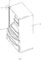
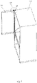
- Fig. 1 is a perspective view of a main body of an electrical apparatus according to a embodiment of the present disclosure
- Fig. 2 is an enlarged view of a portion A as shown in Fig. 1
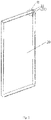
- Fig. 3 is a perspective view of a pivotal part of the electrical apparatus according to the embodiment of the present disclosure
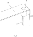
- Fig. 4 is an enlarged view of a portion B as shown in Fig. 3 .
- an electrical apparatus comprising: a main body 10; a pivotal part 20 pivotally connected to the main body 10; a first coil 11 mounted on the main body 10; and a second coil 21 mounted on the pivotal part 20,
- the first coil 11 at least partly passes through the second coil 21 to form electromagnetic coupling between the first coil 11 and the second coil 21, so that power is wirelessly supplied between the main body 10 and the pivot part 20.
- the electrical apparatus comprises a refrigerator 1, and the pivotal part 20 comprises a refrigerator door which is mounted on a refrigerator main body 10 of the refrigerator by a hinge device 12.
- the first coil 11 is acted as a transmitter coil and is in a cylindrical shape
- the second coil 21 is acted as a receiver coil and is in a hollow cylindrical shape.
- the transmitter coil at least partially passes through the receiver coil, and the receiver coil is pivotally moved relative to the transmitter coil about a pivot axis of the hinge device 12.
- the first coil 11 and the second coil 21 are configured to achieve signal transmission from the refrigerator door to the refrigerator main body.
- the hinge device 12 comprises: a mounting portion 13 mounted on the main body 10; and an insertion portion 14 fixed on the mounting portion 13, for example, near a free end of the mounting portion 13, the first coil 11 being arranged in the insertion portion 14.
- the first coil 11 protrudes from the insertion portion 14.
- a receiving groove 22 is provided on the refrigerator door, and the second coil 21 is arranged in the receiving groove 22.
- the insertion portion 14 of the hinge device 12 is inserted into the receiving groove 22, so that the first coil 11 at least partially passes through the second coil 21.
- the hinge device 12 further includes an electric wire(s) 16 connected from the first coil 11 (or the transmitter coil) to a control system of the refrigerator, which is located in the refrigerator main body 10.
- the transmitter coil is adapted to receive power from the refrigerator main body via the electric wire 16 to achieve wireless transmission of power from the transmitter coil to the receiver coil.
- the first coil 11 is adapted to receive a signal from a control system of the electrical apparatus via the electric wire 16 and transmit it to the second coil 21. In a further embodiment, the first coil 11 is adapted to transmit a signal received from the second coil 21 to the control system of the electrical apparatus via the electric wire 16.
- Fig. 5 is a perspective view of the electrical apparatus according to the first embodiment of the present disclosure as viewed from a direction, wherein the pivotal part as shown in Fig. 3 has been mounted on the main body as shown in Fig. 1 ;
- Fig. 6 is an enlarged view of a portion C as shown in Fig. 5 ;
- Fig. 7 is a perspective view of the electrical apparatus as shown in Fig. 5 as viewed from another direction; and
- Fig. 8 is an enlarged view of a portion D as shown in Fig. 7 .
- the insertion portion 14 is constructed as a cylinder.
- the hinge device 12 further includes a plastic body 15, in which the first coil 11 is fixed, and the plastic body 15 is fixed in the cylinder, thereby fixing the first coil 11 in the insertion portion 14.
- the plastic body 15 may be made of a pouring sealant.
- a bearing portion 23 is provided in the receiving groove 22.
- the second coil 21 is fixed to the bearing portion 23, thereby fixing the second coil 21 in the receiving groove 22.
- the second coil 21 is fixed by a double-sided adhesive tape.
- the refrigerator further includes a supporting part 17 mounted at a position of the main body 10 which is engaged with a lower end of the refrigerator door.
- the supporting part 17 is provided with a protrusion 18, the lower end of the refrigerator door is correspondingly provided with a mounting groove 25, and the protrusion 18 is inserted into the mounting groove 25, so as to support the refrigerator door during pivoting movement of the refrigerator door.
- the hinge device 12 is further be configured to support the refrigerator door during the pivoting movement of the refrigerator door.
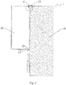
- the refrigerator door When the refrigerator door is mounted to the refrigerator main body 10 by the hinge device 12, a portion of the first coil 11 completely passes through the second coil 21, and the first coil 11 is overlapped with the second coil 21 at a position thereof in the pivot axis of the hinge device 12, thereby generating electromagnetic coupling therebetween.
- the second coil 21 When the refrigerator door is opened or closed, the second coil 21 is pivoted relative to the first coil 11, and a relative position of the first coil 11 and the second coil 21 in the pivot axis remains unchanged throughout the pivoting movement, so that the power may be supplied between the first coil 11 and the second coil 21 in a wireless manner.
- the power may be transmitted from the refrigerator main body to the refrigerator door, and then the power may be supplied to a load(s), such as a display device, on the refrigerator door via an electric wire(s) 24 provided on the second coil 21.
- a load(s) such as a display device
- Fig. 9 is a perspective view of a main body of an electrical apparatus according to anther embodiment of the present disclosure
- Fig. 10 is an enlarged view of a portion E as shown in Fig. 9
- Fig. 11 is a perspective view of a pivotal part of the electrical apparatus according to the another embodiment of the present disclosure
- Fig. 12 is an enlarged view of a portion F as shown in Fig. 11 .
- an electrical apparatus comprising: a main body 110, a pivotal part 120, a first coil 111 and a second coil 121.
- the first coil 111 at least partly passes through the second coil 121 to form electromagnetic coupling between the first coil 111 and the second coil 121, so that power is wirelessly supplied between the main body 110 and the pivot part 120.
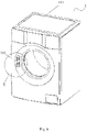
- the electrical apparatus comprises a washing machine 2, and the pivotal part 120 is a washing machine door which is mounted on a main body of the washing machine by a hinge device 112.
- the first coil 111 is acted as a transmitter coil and is in a cylindrical shape
- the second coil 121 is acted as a receiver coil and is in a hollow cylindrical shape.
- the transmitter coil at least partially passes through the receiver coil, and the receiver coil is pivotally moved relative to the transmitter coil about a pivot axis of the hinge device 112.
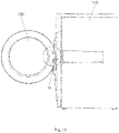
- the first coil 111 and the second coil 121 may be configured to achieve signal transmission from the washing machine door to the main body of the washing machine.
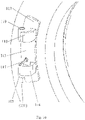
- the hinge device 112 comprises: a base 113 mounted on the main body of the washing machine; a mounting portion 114 mounted on the base 113; and an insertion portion 115 fixed on the mounting portion 114, for example, at a free end of the mounting portion 114, the first coil 111 being arranged in the insertion portion 115.
- the first coil 111 protrudes from the insertion portion 115.
- a receiving groove(s) 122 is provided on the washing machine door, and the second coil 121 is arranged in the receiving groove 122.
- the insertion portion 115 of the hinge device 112 is inserted into the receiving groove 122, so that the first coil 111 at least partially passes through the second coil 121.
- Fig. 13 is a perspective view of the electrical apparatus according to the non-claimed example as viewed from a direction, wherein the pivotal part as shown in Fig. 11 has been mounted on the main body as shown in Fig. 9 ;
- Fig. 14 is an enlarged view of a portion G as shown in Fig. 13 ;
- Fig. 15 is a perspective view of the electrical apparatus as shown in Fig. 13 as viewed from another direction; and
- Fig. 16 is an enlarged view of a portion H as shown in Fig. 15 .
- the insertion portion 115 is constructed as a cylinder.
- the hinge device 112 further includes a plastic body 116, in which the first coil 111 is fixed, and the plastic body 116 is fixed in the cylinder, thereby fixing the first coil 111 in the insertion portion 115.
- the plastic body 116 may be made of a pouring sealant.
- a bearing portion 123 is provided in the receiving groove 122.
- the second coil 121 is fixed to the bearing portion 123, thereby fixing the second coil 121 in the receiving groove 122.
- the second coil 121 is fixed by a double-sided adhesive tape.
- the hinge device 112 further includes an electric wire(s) 117 connected from the first coil 111 (or the transmitter coil) to a control system of the washing machine, which is located in the main body of the washing machine.
- the transmitter coil is adapted to receive the power from the main body of the washing machine via the electric wire 117 to achieve wireless transmission of power from the transmitter coil to the receiver coil.
- the first coil 111 is adapted to receive a signal from a control system of the electrical apparatus via the electric wire 117 and transmit it to the second coil 121.
- the first coil 111 is adapted to transmit a signal received from the second coil 121 to the control system of the electrical apparatus via the electric wire 117.
- the hinge device 112 further includes: a second mounting portion 118 mounted on the base 113 and opposite to the mounting portion 114; and a second insertion portion 119 fixed on the second mounting portion 118 and inserted into the receiving groove 122 in the washing machine door.
- the mounting portion 114 is provided under the second mounting portion 118.
- the mounting portion 114 is provided above the second mounting portion 118.
- the washing machine door When the washing machine door is mounted to the main body of the washing machine by the hinge device 112, a portion of the first coil 111 completely passes through the second coil 121, and the first coil 11 is overlapped with the second coil 21 at a position thereof in the pivot axis of the hinge device 112, thereby generating electromagnetic coupling therebetween.
- the second coil 121 pivots relative to the first coil 111, and a relative position of the first coil 111 and the second coil 121 in the pivot axis remains unchanged throughout the pivoting movement, so that the power may be supplied between the first coil 111 and the second coil 121 in a wireless manner.
- the power may be transmitted from the main body of the washing machine to the washing machine door, and then the power may be supplied to a load(s), such as a display device, on the washing machine door via an electric wire(s) 124 provided on the second coil 121.
- a load(s) such as a display device
- the electrical apparatus by means of wireless power transmission, it is unnecessary to arrange the electrical wires in the hinge hole, thereby simplifying the assembly and disassembly process of the electrical apparatus.
- the number of the electricity consumption devices is not limited by the size of the hinge hole, significantly improving reliability of power supply.
Landscapes
- Engineering & Computer Science (AREA)
- Power Engineering (AREA)
- Computer Networks & Wireless Communication (AREA)
- Chemical & Material Sciences (AREA)
- Combustion & Propulsion (AREA)
- Physics & Mathematics (AREA)
- Mechanical Engineering (AREA)
- Thermal Sciences (AREA)
- General Engineering & Computer Science (AREA)
- Textile Engineering (AREA)
- Selective Calling Equipment (AREA)
Description
- Embodiments and certain non-claimed examples of the present disclosure relate to an electrical apparatus, and in particular to an electrical apparatus enabling wireless power supply between parts which pivot relative to each other.
- In electrical appliances, in particular household appliances, two parts having a relative pivoting movement relationship are generally connected by a hinge device. Because of a need to communicate between the parts, such as a need to transmit power between the parts, wires are required to pass through hinge holes to transmit power from one end of the hinge device to the other.
- However, due to the need to pass the wires through the hinge hole, this arrangement complicates assembly and disassembly processes of the electrical appliances; due to a limited size of the hinge hole, this arrangement makes the hinge hole not accommodate more wires, and therefore the number of power consumption devices is limited; and, since the wire passing through the hinge is driven to reciprocate by the hinge during the pivoting movement, this arrangement is liable to cause fatigue of the wire to fail, greatly reducing reliability of power transmission.
- Therefore, there is a need for an electrical apparatus that may solve the above problems.
-
WO 2017/072659 A1 discloses a wireless power transmission device including: a transmitting coil assembly having a first magnetic core and transmitting coil windings wound around the first magnetic core; and a receiving coil assembly having a second magnetic core and a receiving coil winding wound around the second magnetic core. The first magnetic core includes a U-shaped body portion and first and second pillar portions extending at both ends of the U-shaped body portion. The transmitting coil winding includes first and second transmitting coil windings wound around the first and second pillar portions respectively. The receiving coil winding wound around the second magnetic core includes first and second receiving coil windings wound around both ends of the second magnetic core. The receiving coil assembly is adapted to be interposed between the first pillar portion and the second pillar portion of the transmitting coil assembly to be electromagnetic ally coupled therewith. -
US 2017/0048457 A1 discloses an imaging apparatus including a base that has a power transmitter for transmitting power wirelessly; and a movable unit that has a power receiver for receiving power wirelessly from the power transmitter, an imager operating on the basis of power received by the power receiver, and a first communicator transmitting image information acquired by the imager wirelessly. The movable unit is movable relative to the base. -
JP H08 84891 A -
US 2010/271296 A1 discloses a user interface, e.g. a screen, powered via an inductive coupling and connected to a main body via hinges. - An object of the present disclosure is to solve at least one of the above and other problems and defects existing in the prior arts.
- According to an exemplary embodiment of an aspect of the present disclosure, there is provided an electrical apparatus wherein electromagnetic coupling is formed between a first coil mounted on a main body and a second coil mounted on a pivotal part, realizing wireless power supply between the main body and the pivotal part.
- The first coil at least partly passes through the second coil to form electromagnetic coupling between the first coil and the second coil, so that power is wirelessly supplied between the main body and the pivot part. The pivotal part is mounted on the main body by a hinge device. A relative position of the first coil and the second coil in a pivot axis of the hinge device remains unchanged during a pivoting movement of the pivotal part. Further, the electrical apparatus comprises a refrigerator, and the pivotal part comprises a refrigerator door.
- According to an exemplary embodiment of the present disclosure, the pivotal device comprises: a mounting portion mounted on the main body; and an insertion portion fixed on the mounting portion, the first coil arranged in the insertion portion; and a receiving groove is provided in the pivotal part, the second coil being arranged in the receiving groove, and the insertion portion being inserted into the receiving groove.
- According to an exemplary embodiment of the present disclosure, the insertion portion is constructed to be a cylinder. The hinge device further comprises a plastic body fixed in the cylinder, the first coil being fixed in the plastic body.
- According to an exemplary embodiment of the present disclosure, a bearing portion is provided in the receiving groove, the second coil being fixed to the bearing portion.
- According to an exemplary embodiment of the present disclosure, the first coil is acted as a transmitter coil, the second coil is acted as a receiver coil, and electromagnetic coupling is formed between the first coil and the second coil, so that power is transmitted from the main body to the pivotal part.
- According to an exemplary embodiment of the present disclosure, the electrical apparatus further comprises a supporting part mounted at a position of the main body, which is engaged with a lower end of the pivotal part, and provided with a protrusion, the lower end of the pivotal part being provided with a mounting groove, and the protrusion being inserted into the mounting groove.
- According to an exemplary embodiment of the present disclosure, the first coil is in a cylindrical shape and the second coil is in a hollow cylindrical shape.
- Other objectives and advantages of the present disclosure will become apparent from the following description of the present disclosure when taken in conjunction with the accompanying drawings, and may give a comprehensive understanding of the present disclosure.
- The above and other features of the present disclosure will become more apparent by describing in detail exemplary embodiments thereof with reference to the accompanying drawings, in which:
-
Fig. 1 is a perspective view of a main body of an electrical apparatus according to an embodiment of the present disclosure; -
Fig. 2 is an enlarged view of a portion A as shown inFig. 1 ; -
Fig. 3 is a perspective view of a pivotal part of the electrical apparatus according to the embodiment of the present disclosure; -
Fig. 4 is an enlarged view of a portion B as shown inFig. 3 ; -
Fig. 5 is a perspective view of the electrical apparatus according to the embodiment of the present disclosure as viewed from a direction, wherein the pivotal part as shown inFig. 3 has been mounted on the main body as shown inFig. 1 ; -
Fig. 6 is an enlarged view of a portion C as shown inFig. 5 ; -
Fig. 7 is a perspective view of the electrical apparatus as shown inFig. 5 as viewed from another direction; -
Fig. 8 is an enlarged view of a portion D as shown inFig. 7 ; -
Fig. 9 is a perspective view of a main body of an electrical apparatus according to a non-claimed example; -
Fig. 10 is an enlarged view of a portion E as shown inFig. 9 ; -
Fig. 11 is a perspective view of a pivotal part of the electrical apparatus according to a non-claimed example; -
Fig. 12 is an enlarged view of a portion F as shown inFig. 11 ; -
Fig. 13 is a perspective view of the electrical apparatus according to the non-claimed example as viewed from a direction, wherein the pivotal part as shown inFig. 11 has been mounted on the main body as shown inFig. 9 ; -
Fig. 14 is an enlarged view of a portion G as shown inFig. 13 ; -
Fig. 15 is a perspective view of the electrical apparatus as shown inFig. 13 as viewed from another direction; and -
Fig. 16 is an enlarged view of a portion H as shown inFig. 15 . - The technical solution of the present disclosure will be described hereinafter in further detail with reference to the following embodiments, taken in conjunction with the accompanying drawings. In the specification, the same or similar reference numerals indicate the same or similar parts.
- In addition, in the following detailed description, for the sake of explanation, numerous specific details are set forth in order to provide a thorough understanding of the disclosed embodiments. In other instances, well-known structures and devices are illustrated schematically in order to simplify the drawing.
- According to the invention, there is provided an electrical apparatus according to
claim 1. -
Fig. 1 is a perspective view of a main body of an electrical apparatus according to a embodiment of the present disclosure;Fig. 2 is an enlarged view of a portion A as shown inFig. 1 ;Fig. 3 is a perspective view of a pivotal part of the electrical apparatus according to the embodiment of the present disclosure; andFig. 4 is an enlarged view of a portion B as shown inFig. 3 . - As shown in
Figs. 1-4 , in an illustrated embodiment of the present disclosure, there is provided an electrical apparatus, comprising: amain body 10; apivotal part 20 pivotally connected to themain body 10; afirst coil 11 mounted on themain body 10; and asecond coil 21 mounted on thepivotal part 20, Thefirst coil 11 at least partly passes through thesecond coil 21 to form electromagnetic coupling between thefirst coil 11 and thesecond coil 21, so that power is wirelessly supplied between themain body 10 and thepivot part 20. - Further, according to the invention, the electrical apparatus comprises a
refrigerator 1, and thepivotal part 20 comprises a refrigerator door which is mounted on a refrigeratormain body 10 of the refrigerator by ahinge device 12. As shown inFigs. 1-4 , in an illustrated embodiment of the present disclosure, thefirst coil 11 is acted as a transmitter coil and is in a cylindrical shape, and thesecond coil 21 is acted as a receiver coil and is in a hollow cylindrical shape. The transmitter coil at least partially passes through the receiver coil, and the receiver coil is pivotally moved relative to the transmitter coil about a pivot axis of thehinge device 12. In this way, power may be wirelessly transmitted from the transmitter coil to the receiver coil, thereby realizing power transmission from the refrigerator main body to the refrigerator door. In an alternative embodiment, thefirst coil 11 and thesecond coil 21 are configured to achieve signal transmission from the refrigerator door to the refrigerator main body. - As shown in
Fig. 2 , in an illustrated embodiment of the present disclosure, thehinge device 12 comprises: amounting portion 13 mounted on themain body 10; and aninsertion portion 14 fixed on themounting portion 13, for example, near a free end of themounting portion 13, thefirst coil 11 being arranged in theinsertion portion 14. In the illustrated embodiment, thefirst coil 11 protrudes from theinsertion portion 14. As shown inFig. 4 , a receivinggroove 22 is provided on the refrigerator door, and thesecond coil 21 is arranged in thereceiving groove 22. Theinsertion portion 14 of thehinge device 12 is inserted into the receivinggroove 22, so that thefirst coil 11 at least partially passes through thesecond coil 21. - As shown in
Fig. 2 , in an illustrated embodiment of the present disclosure, thehinge device 12 further includes an electric wire(s) 16 connected from the first coil 11 (or the transmitter coil) to a control system of the refrigerator, which is located in the refrigeratormain body 10. In an exemplary embodiment, the transmitter coil is adapted to receive power from the refrigerator main body via theelectric wire 16 to achieve wireless transmission of power from the transmitter coil to the receiver coil. - In a further embodiment, the
first coil 11 is adapted to receive a signal from a control system of the electrical apparatus via theelectric wire 16 and transmit it to thesecond coil 21. In a further embodiment, thefirst coil 11 is adapted to transmit a signal received from thesecond coil 21 to the control system of the electrical apparatus via theelectric wire 16. -
Fig. 5 is a perspective view of the electrical apparatus according to the first embodiment of the present disclosure as viewed from a direction, wherein the pivotal part as shown inFig. 3 has been mounted on the main body as shown inFig. 1 ;Fig. 6 is an enlarged view of a portion C as shown inFig. 5 ;Fig. 7 is a perspective view of the electrical apparatus as shown inFig. 5 as viewed from another direction; andFig. 8 is an enlarged view of a portion D as shown inFig. 7 . - As shown in
Fig. 2 , theinsertion portion 14 is constructed as a cylinder. As shown inFigs. 5-8 , in an illustrated embodiment of the present disclosure, thehinge device 12 further includes aplastic body 15, in which thefirst coil 11 is fixed, and theplastic body 15 is fixed in the cylinder, thereby fixing thefirst coil 11 in theinsertion portion 14. In an embodiment, theplastic body 15 may be made of a pouring sealant. - As shown in
Figs. 5-8 , in an illustrated embodiment of the present disclosure, a bearingportion 23 is provided in the receivinggroove 22. Thesecond coil 21 is fixed to the bearingportion 23, thereby fixing thesecond coil 21 in the receivinggroove 22. In an embodiment, thesecond coil 21 is fixed by a double-sided adhesive tape. - As shown in
Figs. 1 ,5 and7 , in an illustrated embodiment of the present disclosure, the refrigerator further includes a supportingpart 17 mounted at a position of themain body 10 which is engaged with a lower end of the refrigerator door. The supportingpart 17 is provided with a protrusion 18, the lower end of the refrigerator door is correspondingly provided with a mountinggroove 25, and the protrusion 18 is inserted into the mountinggroove 25, so as to support the refrigerator door during pivoting movement of the refrigerator door. Thehinge device 12 is further be configured to support the refrigerator door during the pivoting movement of the refrigerator door. - When the refrigerator door is mounted to the refrigerator
main body 10 by thehinge device 12, a portion of thefirst coil 11 completely passes through thesecond coil 21, and thefirst coil 11 is overlapped with thesecond coil 21 at a position thereof in the pivot axis of thehinge device 12, thereby generating electromagnetic coupling therebetween. When the refrigerator door is opened or closed, thesecond coil 21 is pivoted relative to thefirst coil 11, and a relative position of thefirst coil 11 and thesecond coil 21 in the pivot axis remains unchanged throughout the pivoting movement, so that the power may be supplied between thefirst coil 11 and thesecond coil 21 in a wireless manner. In an exemplary embodiment of the present disclosure, the power may be transmitted from the refrigerator main body to the refrigerator door, and then the power may be supplied to a load(s), such as a display device, on the refrigerator door via an electric wire(s) 24 provided on thesecond coil 21. -
Fig. 9 is a perspective view of a main body of an electrical apparatus according to anther embodiment of the present disclosure;Fig. 10 is an enlarged view of a portion E as shown inFig. 9 ;Fig. 11 is a perspective view of a pivotal part of the electrical apparatus according to the another embodiment of the present disclosure; andFig. 12 is an enlarged view of a portion F as shown inFig. 11 . - Similar to the first embodiment, as shown in
Figs. 9-12 , in a non-claimed example, is provided an electrical apparatus, comprising: amain body 110, apivotal part 120, afirst coil 111 and asecond coil 121. Thefirst coil 111 at least partly passes through thesecond coil 121 to form electromagnetic coupling between thefirst coil 111 and thesecond coil 121, so that power is wirelessly supplied between themain body 110 and thepivot part 120. - Further, in an example not forming part of the invention, the electrical apparatus comprises a
washing machine 2, and thepivotal part 120 is a washing machine door which is mounted on a main body of the washing machine by ahinge device 112. As shown inFigs. 9-12 , in an illustrated non-claimed example, thefirst coil 111 is acted as a transmitter coil and is in a cylindrical shape, and thesecond coil 121 is acted as a receiver coil and is in a hollow cylindrical shape. The transmitter coil at least partially passes through the receiver coil, and the receiver coil is pivotally moved relative to the transmitter coil about a pivot axis of thehinge device 112. In this way, power may be wirelessly transmitted from the transmitter coil to the receiver coil, thereby realizing power transmission from the main body of the washing machine to the washing machine door. In an alternative, thefirst coil 111 and thesecond coil 121 may be configured to achieve signal transmission from the washing machine door to the main body of the washing machine. - As shown in
Fig. 10 , in an illustrated example not forming part of the invention, thehinge device 112 comprises: a base 113 mounted on the main body of the washing machine; a mountingportion 114 mounted on thebase 113; and aninsertion portion 115 fixed on the mountingportion 114, for example, at a free end of the mountingportion 114, thefirst coil 111 being arranged in theinsertion portion 115. In the illustrated embodiment, thefirst coil 111 protrudes from theinsertion portion 115. As shown inFig. 12 , a receiving groove(s) 122 is provided on the washing machine door, and thesecond coil 121 is arranged in the receivinggroove 122. Theinsertion portion 115 of thehinge device 112 is inserted into the receivinggroove 122, so that thefirst coil 111 at least partially passes through thesecond coil 121. -
Fig. 13 is a perspective view of the electrical apparatus according to the non-claimed example as viewed from a direction, wherein the pivotal part as shown inFig. 11 has been mounted on the main body as shown inFig. 9 ;Fig. 14 is an enlarged view of a portion G as shown inFig. 13 ;Fig. 15 is a perspective view of the electrical apparatus as shown inFig. 13 as viewed from another direction; andFig. 16 is an enlarged view of a portion H as shown inFig. 15 . - As shown in
Fig. 10 , theinsertion portion 115 is constructed as a cylinder. As shown inFigs. 13-16 , in an illustrated non-claimed example, thehinge device 112 further includes aplastic body 116, in which thefirst coil 111 is fixed, and theplastic body 116 is fixed in the cylinder, thereby fixing thefirst coil 111 in theinsertion portion 115. Theplastic body 116 may be made of a pouring sealant. - As shown in
Figs. 9-16 , in an illustrated non-claimed example, a bearingportion 123 is provided in the receivinggroove 122. Thesecond coil 121 is fixed to the bearingportion 123, thereby fixing thesecond coil 121 in the receivinggroove 122. Thesecond coil 121 is fixed by a double-sided adhesive tape. - As shown in
Fig. 14 , in an illustrated example not forming part of the invention, thehinge device 112 further includes an electric wire(s) 117 connected from the first coil 111 (or the transmitter coil) to a control system of the washing machine, which is located in the main body of the washing machine. In a non-claimed example, the transmitter coil is adapted to receive the power from the main body of the washing machine via theelectric wire 117 to achieve wireless transmission of power from the transmitter coil to the receiver coil. In a further non-claimed example, thefirst coil 111 is adapted to receive a signal from a control system of the electrical apparatus via theelectric wire 117 and transmit it to thesecond coil 121. In a further non-claimed example, thefirst coil 111 is adapted to transmit a signal received from thesecond coil 121 to the control system of the electrical apparatus via theelectric wire 117. - As shown in
Figs. 10 ,14 and16 , in an illustrated example not forming part of the invention, thehinge device 112 further includes: a second mountingportion 118 mounted on thebase 113 and opposite to the mountingportion 114; and asecond insertion portion 119 fixed on the second mountingportion 118 and inserted into the receivinggroove 122 in the washing machine door. In the exemplary embodiment, the mountingportion 114 is provided under the second mountingportion 118. In an alternative non-claimed example, the mountingportion 114 is provided above the second mountingportion 118. - When the washing machine door is mounted to the main body of the washing machine by the
hinge device 112, a portion of thefirst coil 111 completely passes through thesecond coil 121, and thefirst coil 11 is overlapped with thesecond coil 21 at a position thereof in the pivot axis of thehinge device 112, thereby generating electromagnetic coupling therebetween. When the washing machine door is opened or closed, thesecond coil 121 pivots relative to thefirst coil 111, and a relative position of thefirst coil 111 and thesecond coil 121 in the pivot axis remains unchanged throughout the pivoting movement, so that the power may be supplied between thefirst coil 111 and thesecond coil 121 in a wireless manner. In an example not forming part of the invention, the power may be transmitted from the main body of the washing machine to the washing machine door, and then the power may be supplied to a load(s), such as a display device, on the washing machine door via an electric wire(s) 124 provided on thesecond coil 121. - Thus, in the electrical apparatus according to the embodiment of the present disclosure, by means of wireless power transmission, it is unnecessary to arrange the electrical wires in the hinge hole, thereby simplifying the assembly and disassembly process of the electrical apparatus. The number of the electricity consumption devices is not limited by the size of the hinge hole, significantly improving reliability of power supply.
- It should be noted that term "comprising" or "including" should be understood as not excluding other elements or steps, and term "a" or "an" should be understood as not excluding plural elements or steps.
Claims (7)
- An electrical apparatus comprising:a main body (10);a pivotal part (20) pivotally connected to the main body (10);a first coil (11) mounted on the main body (10); anda second coil (21) mounted on the pivotal part (20);wherein the pivotal part (20) is mounted on the main body (10) by a hinge device (12);wherein the first coil (11) at least partly passes through the second coil (21) to form electromagnetic coupling between the first coil and the second coil, so that power is wirelessly supplied between the main body and the pivotal part, and wherein a relative position of the first coil and the second coil in a pivot axis of the hinge device remains unchanged during a pivoting movement of the pivotal part, wherein the electrical apparatus comprises a refrigerator, and the pivotal part comprises a refrigerator door.
- The electrical apparatus according to claim 1, wherein the hinge device (12) comprises:a mounting portion (13) mounted on the main body (10); andan insertion portion (14) fixed on the mounting portion, the first coil (11) being arranged in the insertion portion; andwherein a receiving groove (22) is provided in the pivotal part, the second coil being arranged in the receiving groove, and the insertion portion being inserted into the receiving groove.
- The electrical apparatus according to claim 2, wherein the insertion portion (14) is constructed as a cylinder, and
wherein the hinge device (12) further comprises a plastic body (15) fixed in the cylinder, the first coil being fixed in the plastic body. - The electrical apparatus according to claim 3, wherein a bearing portion (23) is provided in the receiving groove (22), the second coil (21) being fixed to the bearing portion.
- The electrical apparatus according to claim 4, wherein the first coil (11) is acted as a transmitter coil, the second coil (21) is acted as a receiver coil, and electromagnetic coupling is formed between the first coil and the second coil, so that power is transmitted from the main body to the pivotal part.
- The electrical apparatus according to claim 1, further comprising a supporting part (17) mounted at a position of the main body, which is engaged with a lower end of the pivotal part, and provided with a protrusion (18), the lower end of the pivotal part being provided with a mounting groove (25), and the protrusion being inserted into the mounting groove.
- The electrical apparatus according to claim 1, wherein the first coil (11) is in a cylindrical shape and the second coil (21) is in a hollow cylindrical shape.
Applications Claiming Priority (1)
| Application Number | Priority Date | Filing Date | Title |
|---|---|---|---|
| CN201810718103.XA CN110676943B (en) | 2018-07-03 | 2018-07-03 | Electrical Equipment |
Publications (2)
| Publication Number | Publication Date |
|---|---|
| EP3591321A1 EP3591321A1 (en) | 2020-01-08 |
| EP3591321B1 true EP3591321B1 (en) | 2022-04-27 |
Family
ID=67105799
Family Applications (1)
| Application Number | Title | Priority Date | Filing Date |
|---|---|---|---|
| EP19182754.2A Active EP3591321B1 (en) | 2018-07-03 | 2019-06-27 | Electrical apparatus |
Country Status (3)
| Country | Link |
|---|---|
| US (1) | US11177692B2 (en) |
| EP (1) | EP3591321B1 (en) |
| CN (1) | CN110676943B (en) |
Families Citing this family (1)
| Publication number | Priority date | Publication date | Assignee | Title |
|---|---|---|---|---|
| CN113531974A (en) * | 2020-04-20 | 2021-10-22 | 青岛海尔电冰箱有限公司 | Refrigerator with a door |
Citations (3)
| Publication number | Priority date | Publication date | Assignee | Title |
|---|---|---|---|---|
| JPH0884891A (en) * | 1994-09-20 | 1996-04-02 | Hitachi Ltd | Washing machine |
| US20100271296A1 (en) * | 2009-04-24 | 2010-10-28 | Baxter International Inc. | User interface powered via an inductive coupling |
| WO2020196974A1 (en) * | 2019-03-26 | 2020-10-01 | 엘지전자 주식회사 | Laundry treatment device |
Family Cites Families (17)
| Publication number | Priority date | Publication date | Assignee | Title |
|---|---|---|---|---|
| JPH09103036A (en) * | 1995-09-12 | 1997-04-15 | Kokusai Electric Co Ltd | Contactless power supply device for electronic circuits |
| JPH09317346A (en) * | 1996-05-27 | 1997-12-09 | Matsushita Electric Works Ltd | Non-contact power supply door construction |
| JP2000085492A (en) * | 1998-09-11 | 2000-03-28 | Harness Syst Tech Res Ltd | Power supply for door |
| JP3727808B2 (en) * | 1999-08-13 | 2005-12-21 | 株式会社オートネットワーク技術研究所 | Electromagnetic induction type energizer |
| DE20305769U1 (en) * | 2003-04-09 | 2003-10-30 | Staude, Wolfgang, 34513 Waldeck | Hinge with built-in transformer for contactless energy transfer |
| JP2007318890A (en) * | 2006-05-25 | 2007-12-06 | Tsuuden:Kk | Non-contact feeder system for automatic door |
| DE102011050342A1 (en) * | 2011-05-13 | 2012-11-15 | Dr. Hahn Gmbh & Co. Kg | Method and device for contactless transmission of electrical energy between a wall and a wing attached to this wall |
| DE202011000613U1 (en) * | 2011-03-17 | 2012-06-20 | Dr. Hahn Gmbh & Co. Kg | Device for transmitting electrical energy and / or electrical signals from a fixed wall to a wall-mounted wing |
| PL2527574T3 (en) * | 2011-05-24 | 2014-08-29 | Hahn Gmbh & Co Kg Dr | Device for contactless transfer of electrical energy between a wall and a leaf fixed to this wall |
| CN202645229U (en) * | 2012-07-12 | 2013-01-02 | 胡娣星 | Door hinge capable of being disassembled and assembled |
| DE102013114319A1 (en) * | 2013-12-18 | 2015-06-18 | Dr. Hahn Gmbh & Co. Kg | Method and device for transmitting electric power and signals between a wall and a wing which is pivotable with respect to it |
| CN105098998B (en) | 2014-05-16 | 2020-02-11 | 泰科电子(上海)有限公司 | Wireless power transmission device |
| JP6347361B2 (en) * | 2014-05-27 | 2018-06-27 | パナソニックIpマネジメント株式会社 | Imaging device |
| CN205141843U (en) * | 2015-10-26 | 2016-04-06 | 泰科电子(上海)有限公司 | Wireless power transmission device and electrical equipment |
| JP6493351B2 (en) * | 2016-10-11 | 2019-04-03 | Tdk株式会社 | Rotary magnetic coupling device |
| CN107658996A (en) * | 2017-11-16 | 2018-02-02 | 中国电子科技集团公司第三十八研究所 | Rotary non-contact electric energy transmission device |
| CN208608786U (en) * | 2018-07-03 | 2019-03-15 | 泰科电子(上海)有限公司 | Electrical equipment |
-
2018
- 2018-07-03 CN CN201810718103.XA patent/CN110676943B/en active Active
-
2019
- 2019-06-27 EP EP19182754.2A patent/EP3591321B1/en active Active
- 2019-07-02 US US16/460,339 patent/US11177692B2/en active Active
Patent Citations (3)
| Publication number | Priority date | Publication date | Assignee | Title |
|---|---|---|---|---|
| JPH0884891A (en) * | 1994-09-20 | 1996-04-02 | Hitachi Ltd | Washing machine |
| US20100271296A1 (en) * | 2009-04-24 | 2010-10-28 | Baxter International Inc. | User interface powered via an inductive coupling |
| WO2020196974A1 (en) * | 2019-03-26 | 2020-10-01 | 엘지전자 주식회사 | Laundry treatment device |
Also Published As
| Publication number | Publication date |
|---|---|
| US11177692B2 (en) | 2021-11-16 |
| EP3591321A1 (en) | 2020-01-08 |
| CN110676943B (en) | 2025-06-24 |
| US20200014242A1 (en) | 2020-01-09 |
| CN110676943A (en) | 2020-01-10 |
Similar Documents
| Publication | Publication Date | Title |
|---|---|---|
| EP3314782B1 (en) | A rotatable antenna apparatus | |
| US10916371B2 (en) | Wireless power transmission device and electrical apparatus | |
| EP3591321B1 (en) | Electrical apparatus | |
| US20160064997A1 (en) | Wireless charging system for variable charging mode | |
| JPWO2010143292A1 (en) | Electromagnetic coupling device and vehicle door | |
| CN108958103A (en) | Control method, controlled method and device, intelligent terminal and intelligent electric appliance | |
| WO2014125725A1 (en) | Rotary electric machine | |
| CN109981426A (en) | Intelligent appliance equipment, Intelligent control equipment and Bluetooth pairing system and method | |
| CN104185890A (en) | coil assembly | |
| CN103430409B (en) | Employ the mode of operation checkout gear of the control machine of IC tag, rotary switching mechanism and test adaptor | |
| KR101671003B1 (en) | Wireless charging apparatus of wearable system for washing machine and method thereof | |
| CN220962784U (en) | Household appliance | |
| CN209177744U (en) | A kind of winding collection device of antenna | |
| CN111614168A (en) | Wireless power supply, electrical equipment | |
| CN214828022U (en) | Electronic tensioner for weaving machine | |
| EP1848230B1 (en) | Configuring parameters of GPRS-type communication devices over a cellular phone network | |
| CN211112777U (en) | Drum type washing machine door body electrifying structure and drum type washing machine | |
| KR20140127604A (en) | Antenna device | |
| KR20150009807A (en) | Method and apparatus for communication using smart module in home network system | |
| CN210150546U (en) | Elevator projection device | |
| KR102000958B1 (en) | Apparatus and method for controlling wireless power transmission | |
| JP2019030076A (en) | Non-contact electric conduction device | |
| JP2019030077A (en) | Non-contact electric conduction device | |
| CN110820250B (en) | Wire fixing bracket, fixing bracket mounting structure and washing machine | |
| CN222146028U (en) | An integrated rotating shaft of a dual power conversion switch |
Legal Events
| Date | Code | Title | Description |
|---|---|---|---|
| PUAI | Public reference made under article 153(3) epc to a published international application that has entered the european phase |
Free format text: ORIGINAL CODE: 0009012 |
|
| STAA | Information on the status of an ep patent application or granted ep patent |
Free format text: STATUS: THE APPLICATION HAS BEEN PUBLISHED |
|
| AK | Designated contracting states |
Kind code of ref document: A1 Designated state(s): AL AT BE BG CH CY CZ DE DK EE ES FI FR GB GR HR HU IE IS IT LI LT LU LV MC MK MT NL NO PL PT RO RS SE SI SK SM TR |
|
| AX | Request for extension of the european patent |
Extension state: BA ME |
|
| STAA | Information on the status of an ep patent application or granted ep patent |
Free format text: STATUS: REQUEST FOR EXAMINATION WAS MADE |
|
| 17P | Request for examination filed |
Effective date: 20200325 |
|
| RBV | Designated contracting states (corrected) |
Designated state(s): AL AT BE BG CH CY CZ DE DK EE ES FI FR GB GR HR HU IE IS IT LI LT LU LV MC MK MT NL NO PL PT RO RS SE SI SK SM TR |
|
| STAA | Information on the status of an ep patent application or granted ep patent |
Free format text: STATUS: EXAMINATION IS IN PROGRESS |
|
| 17Q | First examination report despatched |
Effective date: 20210618 |
|
| GRAP | Despatch of communication of intention to grant a patent |
Free format text: ORIGINAL CODE: EPIDOSNIGR1 |
|
| STAA | Information on the status of an ep patent application or granted ep patent |
Free format text: STATUS: GRANT OF PATENT IS INTENDED |
|
| INTG | Intention to grant announced |
Effective date: 20211122 |
|
| GRAS | Grant fee paid |
Free format text: ORIGINAL CODE: EPIDOSNIGR3 |
|
| GRAA | (expected) grant |
Free format text: ORIGINAL CODE: 0009210 |
|
| STAA | Information on the status of an ep patent application or granted ep patent |
Free format text: STATUS: THE PATENT HAS BEEN GRANTED |
|
| AK | Designated contracting states |
Kind code of ref document: B1 Designated state(s): AL AT BE BG CH CY CZ DE DK EE ES FI FR GB GR HR HU IE IS IT LI LT LU LV MC MK MT NL NO PL PT RO RS SE SI SK SM TR |
|
| REG | Reference to a national code |
Ref country code: GB Ref legal event code: FG4D |
|
| REG | Reference to a national code |
Ref country code: CH Ref legal event code: EP |
|
| REG | Reference to a national code |
Ref country code: DE Ref legal event code: R096 Ref document number: 602019014047 Country of ref document: DE |
|
| REG | Reference to a national code |
Ref country code: AT Ref legal event code: REF Ref document number: 1487220 Country of ref document: AT Kind code of ref document: T Effective date: 20220515 |
|
| REG | Reference to a national code |
Ref country code: IE Ref legal event code: FG4D |
|
| REG | Reference to a national code |
Ref country code: LT Ref legal event code: MG9D |
|
| REG | Reference to a national code |
Ref country code: NL Ref legal event code: MP Effective date: 20220427 |
|
| REG | Reference to a national code |
Ref country code: AT Ref legal event code: MK05 Ref document number: 1487220 Country of ref document: AT Kind code of ref document: T Effective date: 20220427 |
|
| PG25 | Lapsed in a contracting state [announced via postgrant information from national office to epo] |
Ref country code: NL Free format text: LAPSE BECAUSE OF FAILURE TO SUBMIT A TRANSLATION OF THE DESCRIPTION OR TO PAY THE FEE WITHIN THE PRESCRIBED TIME-LIMIT Effective date: 20220427 |
|
| PG25 | Lapsed in a contracting state [announced via postgrant information from national office to epo] |
Ref country code: SE Free format text: LAPSE BECAUSE OF FAILURE TO SUBMIT A TRANSLATION OF THE DESCRIPTION OR TO PAY THE FEE WITHIN THE PRESCRIBED TIME-LIMIT Effective date: 20220427 Ref country code: PT Free format text: LAPSE BECAUSE OF FAILURE TO SUBMIT A TRANSLATION OF THE DESCRIPTION OR TO PAY THE FEE WITHIN THE PRESCRIBED TIME-LIMIT Effective date: 20220829 Ref country code: NO Free format text: LAPSE BECAUSE OF FAILURE TO SUBMIT A TRANSLATION OF THE DESCRIPTION OR TO PAY THE FEE WITHIN THE PRESCRIBED TIME-LIMIT Effective date: 20220727 Ref country code: LT Free format text: LAPSE BECAUSE OF FAILURE TO SUBMIT A TRANSLATION OF THE DESCRIPTION OR TO PAY THE FEE WITHIN THE PRESCRIBED TIME-LIMIT Effective date: 20220427 Ref country code: HR Free format text: LAPSE BECAUSE OF FAILURE TO SUBMIT A TRANSLATION OF THE DESCRIPTION OR TO PAY THE FEE WITHIN THE PRESCRIBED TIME-LIMIT Effective date: 20220427 Ref country code: GR Free format text: LAPSE BECAUSE OF FAILURE TO SUBMIT A TRANSLATION OF THE DESCRIPTION OR TO PAY THE FEE WITHIN THE PRESCRIBED TIME-LIMIT Effective date: 20220728 Ref country code: FI Free format text: LAPSE BECAUSE OF FAILURE TO SUBMIT A TRANSLATION OF THE DESCRIPTION OR TO PAY THE FEE WITHIN THE PRESCRIBED TIME-LIMIT Effective date: 20220427 Ref country code: ES Free format text: LAPSE BECAUSE OF FAILURE TO SUBMIT A TRANSLATION OF THE DESCRIPTION OR TO PAY THE FEE WITHIN THE PRESCRIBED TIME-LIMIT Effective date: 20220427 Ref country code: BG Free format text: LAPSE BECAUSE OF FAILURE TO SUBMIT A TRANSLATION OF THE DESCRIPTION OR TO PAY THE FEE WITHIN THE PRESCRIBED TIME-LIMIT Effective date: 20220727 Ref country code: AT Free format text: LAPSE BECAUSE OF FAILURE TO SUBMIT A TRANSLATION OF THE DESCRIPTION OR TO PAY THE FEE WITHIN THE PRESCRIBED TIME-LIMIT Effective date: 20220427 |
|
| PG25 | Lapsed in a contracting state [announced via postgrant information from national office to epo] |
Ref country code: RS Free format text: LAPSE BECAUSE OF FAILURE TO SUBMIT A TRANSLATION OF THE DESCRIPTION OR TO PAY THE FEE WITHIN THE PRESCRIBED TIME-LIMIT Effective date: 20220427 Ref country code: PL Free format text: LAPSE BECAUSE OF FAILURE TO SUBMIT A TRANSLATION OF THE DESCRIPTION OR TO PAY THE FEE WITHIN THE PRESCRIBED TIME-LIMIT Effective date: 20220427 Ref country code: LV Free format text: LAPSE BECAUSE OF FAILURE TO SUBMIT A TRANSLATION OF THE DESCRIPTION OR TO PAY THE FEE WITHIN THE PRESCRIBED TIME-LIMIT Effective date: 20220427 Ref country code: IS Free format text: LAPSE BECAUSE OF FAILURE TO SUBMIT A TRANSLATION OF THE DESCRIPTION OR TO PAY THE FEE WITHIN THE PRESCRIBED TIME-LIMIT Effective date: 20220827 |
|
| REG | Reference to a national code |
Ref country code: DE Ref legal event code: R097 Ref document number: 602019014047 Country of ref document: DE |
|
| PG25 | Lapsed in a contracting state [announced via postgrant information from national office to epo] |
Ref country code: SM Free format text: LAPSE BECAUSE OF FAILURE TO SUBMIT A TRANSLATION OF THE DESCRIPTION OR TO PAY THE FEE WITHIN THE PRESCRIBED TIME-LIMIT Effective date: 20220427 Ref country code: SK Free format text: LAPSE BECAUSE OF FAILURE TO SUBMIT A TRANSLATION OF THE DESCRIPTION OR TO PAY THE FEE WITHIN THE PRESCRIBED TIME-LIMIT Effective date: 20220427 Ref country code: RO Free format text: LAPSE BECAUSE OF FAILURE TO SUBMIT A TRANSLATION OF THE DESCRIPTION OR TO PAY THE FEE WITHIN THE PRESCRIBED TIME-LIMIT Effective date: 20220427 Ref country code: MC Free format text: LAPSE BECAUSE OF FAILURE TO SUBMIT A TRANSLATION OF THE DESCRIPTION OR TO PAY THE FEE WITHIN THE PRESCRIBED TIME-LIMIT Effective date: 20220427 Ref country code: EE Free format text: LAPSE BECAUSE OF FAILURE TO SUBMIT A TRANSLATION OF THE DESCRIPTION OR TO PAY THE FEE WITHIN THE PRESCRIBED TIME-LIMIT Effective date: 20220427 Ref country code: DK Free format text: LAPSE BECAUSE OF FAILURE TO SUBMIT A TRANSLATION OF THE DESCRIPTION OR TO PAY THE FEE WITHIN THE PRESCRIBED TIME-LIMIT Effective date: 20220427 Ref country code: CZ Free format text: LAPSE BECAUSE OF FAILURE TO SUBMIT A TRANSLATION OF THE DESCRIPTION OR TO PAY THE FEE WITHIN THE PRESCRIBED TIME-LIMIT Effective date: 20220427 |
|
| REG | Reference to a national code |
Ref country code: CH Ref legal event code: PL |
|
| REG | Reference to a national code |
Ref country code: BE Ref legal event code: MM Effective date: 20220630 |
|
| PLBE | No opposition filed within time limit |
Free format text: ORIGINAL CODE: 0009261 |
|
| STAA | Information on the status of an ep patent application or granted ep patent |
Free format text: STATUS: NO OPPOSITION FILED WITHIN TIME LIMIT |
|
| PG25 | Lapsed in a contracting state [announced via postgrant information from national office to epo] |
Ref country code: AL Free format text: LAPSE BECAUSE OF FAILURE TO SUBMIT A TRANSLATION OF THE DESCRIPTION OR TO PAY THE FEE WITHIN THE PRESCRIBED TIME-LIMIT Effective date: 20220427 |
|
| 26N | No opposition filed |
Effective date: 20230130 |
|
| PG25 | Lapsed in a contracting state [announced via postgrant information from national office to epo] |
Ref country code: LI Free format text: LAPSE BECAUSE OF NON-PAYMENT OF DUE FEES Effective date: 20220630 Ref country code: IE Free format text: LAPSE BECAUSE OF NON-PAYMENT OF DUE FEES Effective date: 20220627 Ref country code: CH Free format text: LAPSE BECAUSE OF NON-PAYMENT OF DUE FEES Effective date: 20220630 Ref country code: LU Free format text: LAPSE BECAUSE OF NON-PAYMENT OF DUE FEES Effective date: 20220627 |
|
| PG25 | Lapsed in a contracting state [announced via postgrant information from national office to epo] |
Ref country code: SI Free format text: LAPSE BECAUSE OF FAILURE TO SUBMIT A TRANSLATION OF THE DESCRIPTION OR TO PAY THE FEE WITHIN THE PRESCRIBED TIME-LIMIT Effective date: 20220427 Ref country code: BE Free format text: LAPSE BECAUSE OF NON-PAYMENT OF DUE FEES Effective date: 20220630 |
|
| PG25 | Lapsed in a contracting state [announced via postgrant information from national office to epo] |
Ref country code: MK Free format text: LAPSE BECAUSE OF FAILURE TO SUBMIT A TRANSLATION OF THE DESCRIPTION OR TO PAY THE FEE WITHIN THE PRESCRIBED TIME-LIMIT Effective date: 20220427 Ref country code: CY Free format text: LAPSE BECAUSE OF FAILURE TO SUBMIT A TRANSLATION OF THE DESCRIPTION OR TO PAY THE FEE WITHIN THE PRESCRIBED TIME-LIMIT Effective date: 20220427 |
|
| PG25 | Lapsed in a contracting state [announced via postgrant information from national office to epo] |
Ref country code: HU Free format text: LAPSE BECAUSE OF FAILURE TO SUBMIT A TRANSLATION OF THE DESCRIPTION OR TO PAY THE FEE WITHIN THE PRESCRIBED TIME-LIMIT; INVALID AB INITIO Effective date: 20190627 |
|
| PG25 | Lapsed in a contracting state [announced via postgrant information from national office to epo] |
Ref country code: MT Free format text: LAPSE BECAUSE OF FAILURE TO SUBMIT A TRANSLATION OF THE DESCRIPTION OR TO PAY THE FEE WITHIN THE PRESCRIBED TIME-LIMIT Effective date: 20220427 |
|
| PG25 | Lapsed in a contracting state [announced via postgrant information from national office to epo] |
Ref country code: BG Free format text: LAPSE BECAUSE OF FAILURE TO SUBMIT A TRANSLATION OF THE DESCRIPTION OR TO PAY THE FEE WITHIN THE PRESCRIBED TIME-LIMIT Effective date: 20220427 |
|
| PG25 | Lapsed in a contracting state [announced via postgrant information from national office to epo] |
Ref country code: BG Free format text: LAPSE BECAUSE OF FAILURE TO SUBMIT A TRANSLATION OF THE DESCRIPTION OR TO PAY THE FEE WITHIN THE PRESCRIBED TIME-LIMIT Effective date: 20220427 |
|
| PGFP | Annual fee paid to national office [announced via postgrant information from national office to epo] |
Ref country code: DE Payment date: 20250402 Year of fee payment: 7 |
|
| PGFP | Annual fee paid to national office [announced via postgrant information from national office to epo] |
Ref country code: GB Payment date: 20250401 Year of fee payment: 7 |
|
| PGFP | Annual fee paid to national office [announced via postgrant information from national office to epo] |
Ref country code: IT Payment date: 20250522 Year of fee payment: 7 |
|
| PGFP | Annual fee paid to national office [announced via postgrant information from national office to epo] |
Ref country code: FR Payment date: 20250508 Year of fee payment: 7 |
|
| PGFP | Annual fee paid to national office [announced via postgrant information from national office to epo] |
Ref country code: TR Payment date: 20250620 Year of fee payment: 7 |