EP3591235A1 - Impeller and rotary machine - Google Patents
Impeller and rotary machine Download PDFInfo
- Publication number
- EP3591235A1 EP3591235A1 EP18761771.7A EP18761771A EP3591235A1 EP 3591235 A1 EP3591235 A1 EP 3591235A1 EP 18761771 A EP18761771 A EP 18761771A EP 3591235 A1 EP3591235 A1 EP 3591235A1
- Authority
- EP
- European Patent Office
- Prior art keywords
- blade
- primary
- axis
- disk
- blades
- Prior art date
- Legal status (The legal status is an assumption and is not a legal conclusion. Google has not performed a legal analysis and makes no representation as to the accuracy of the status listed.)
- Granted
Links
Images


Classifications
-
- F—MECHANICAL ENGINEERING; LIGHTING; HEATING; WEAPONS; BLASTING
- F04—POSITIVE - DISPLACEMENT MACHINES FOR LIQUIDS; PUMPS FOR LIQUIDS OR ELASTIC FLUIDS
- F04D—NON-POSITIVE-DISPLACEMENT PUMPS
- F04D29/00—Details, component parts, or accessories
- F04D29/26—Rotors specially for elastic fluids
- F04D29/28—Rotors specially for elastic fluids for centrifugal or helico-centrifugal pumps for radial-flow or helico-centrifugal pumps
- F04D29/284—Rotors specially for elastic fluids for centrifugal or helico-centrifugal pumps for radial-flow or helico-centrifugal pumps for compressors
-
- F—MECHANICAL ENGINEERING; LIGHTING; HEATING; WEAPONS; BLASTING
- F04—POSITIVE - DISPLACEMENT MACHINES FOR LIQUIDS; PUMPS FOR LIQUIDS OR ELASTIC FLUIDS
- F04D—NON-POSITIVE-DISPLACEMENT PUMPS
- F04D29/00—Details, component parts, or accessories
- F04D29/26—Rotors specially for elastic fluids
- F04D29/28—Rotors specially for elastic fluids for centrifugal or helico-centrifugal pumps for radial-flow or helico-centrifugal pumps
- F04D29/30—Vanes
-
- F—MECHANICAL ENGINEERING; LIGHTING; HEATING; WEAPONS; BLASTING
- F04—POSITIVE - DISPLACEMENT MACHINES FOR LIQUIDS; PUMPS FOR LIQUIDS OR ELASTIC FLUIDS
- F04D—NON-POSITIVE-DISPLACEMENT PUMPS
- F04D17/00—Radial-flow pumps, e.g. centrifugal pumps; Helico-centrifugal pumps
- F04D17/08—Centrifugal pumps
- F04D17/10—Centrifugal pumps for compressing or evacuating
- F04D17/12—Multi-stage pumps
- F04D17/122—Multi-stage pumps the individual rotor discs being, one for each stage, on a common shaft and axially spaced, e.g. conventional centrifugal multi- stage compressors
-
- F—MECHANICAL ENGINEERING; LIGHTING; HEATING; WEAPONS; BLASTING
- F04—POSITIVE - DISPLACEMENT MACHINES FOR LIQUIDS; PUMPS FOR LIQUIDS OR ELASTIC FLUIDS
- F04D—NON-POSITIVE-DISPLACEMENT PUMPS
- F04D29/00—Details, component parts, or accessories
- F04D29/26—Rotors specially for elastic fluids
- F04D29/28—Rotors specially for elastic fluids for centrifugal or helico-centrifugal pumps for radial-flow or helico-centrifugal pumps
- F04D29/281—Rotors specially for elastic fluids for centrifugal or helico-centrifugal pumps for radial-flow or helico-centrifugal pumps for fans or blowers
Definitions
- the present invention relates to an impeller and a rotary machine.
- rotary machines used in industrial compressors, turbo refrigerators, small-sized gas turbines, pumps, and the like
- rotary machines including an impeller in which a plurality of blades are attached to a disk that is fixed to a rotary shaft are known.
- the foregoing rotary machines apply pressure energy and speed energy to a gas by rotating the impeller (for example, refer to Patent Literature 1).
- Patent Literature 1 Japanese Unexamined Patent Application, First Publication No. H9-310697
- the present invention provides an impeller which can obtain greater lift, and a rotary machine including the impeller.
- an impeller includes a disk that has a disk shape and is configured to rotate around an axis, and a plurality of blades that are provided at intervals in a circumferential direction on a side of a surface of the disk directed in a direction of the axis and extend to a rear side in a rotation direction as the plurality of the blades go toward an outer side in a radial direction.
- Each of the plurality of the blades has a primary blade which extends to the rear side in the rotation direction as the primary blade goes from an inner side toward the outer side in the radial direction and of which a rear edge is positioned on the inner side with respect to an outer circumferential edge portion of the disk in the radial direction; and a secondary blade which is provided at intervals on a side in front of the primary blade in the rotation direction to correspond to the primary blade, of which a front edge is positioned on the outer side of a front edge of the primary blade in the radial direction, and of which a rear edge is positioned on the outer circumferential edge portion of the disk.
- a border layer which grows as it goes toward the downstream side on a pressure surface (surface toward the front side in the rotation direction) of the primary blade is cut off between the rear edge of the primary blade and the front edge of the secondary blade.
- a flow including the cut border layer is transferred to an outer circumferential edge of the disk by the pressure surface of the secondary blade. Accordingly, greater lift can be obtained.
- the border layer is temporarily reset between the primary blade and the secondary blade. Therefore, lift can be effectively obtained thereafter by the secondary blade, and greater lift can be realized in the impeller overall.
- a rear edge side region on a pressure surface of the primary blade and a front edge side region on a suction surface of the secondary blade corresponding to the primary blade may face each other.
- the rear edge side region on the pressure surface of the primary blade and the front edge side region on the suction surface of the secondary blade overlap each other in a direction orthogonal to a flow of a fluid. Therefore, the border layer which has grown on the pressure surface of the primary blade is cut off by the front edge on the suction surface and is transferred as it stands to the outer side in the radial direction along the pressure surface of the primary blade. Therefore, the border layer can be more reliably cut off by a flow between the primary blades.
- the primary blade since the primary blade does not lead to the outer circumferential edge portion of the disk, the primary blade does not cause peeling.
- the secondary blade be disposed close to the corresponding primary blade of a pair of primary blades adjacent to each other.
- the secondary blade may have a plurality of stages of secondary blade pieces sequentially arranged toward the outer side in the radial direction, and a front edge of the secondary blade piece on a rear stage side of adjacent secondary blade pieces may be positioned on a side in front of a rear edge of the secondary blade piece on a front stage side in the rotation direction.
- a border layer which may be present in a flow to be transferred by the secondary blades can be cut off between the secondary blade pieces adjacent to each other.
- lift can be more effectively obtained by the entire secondary blades.
- the foregoing impeller may further include a cover that covers the plurality of blades in the direction of the axis.
- a region between the disk and the cover facing each other in the direction of the axis is divided into a disk side region, a cover side region, and a central region between the disk side region and the cover side region, the secondary blade may not be provided in the central region but may be provided in at least one of the disk side region and the cover side region.
- a chord length of the secondary blade be within a range of 5% to 30% of a chord length of the primary blade.
- chord length of the secondary blade is excessively long, the pressure surface of the primary blade is hindered from supplying energy to a flow. In addition, if the chord length of the secondary blade is excessively short, the supply amount of energy of the pressure surface of the secondary blade with respect to a flow after the border layer is cut off is reduced.
- Energy supplied to a fluid by the primary blade and the secondary blade can be optimized by setting the chord length of the secondary blade within the foregoing range.
- energy supplied to a fluid by the primary blade and the secondary blade can be optimized.
- a rotary machine including any of the impellers described above.
- a compressor 1 includes a rotary shaft 2, journal bearings 5, a thrust bearing 6, impellers 20, and a casing 10.
- the compressor 1 of the present embodiment is a so-called single-shaft multi-stage compressor including a plurality of stages of the impellers 20.
- the rotary shaft 2 has a columnar shape extending in a direction of an axis O laid in the horizontal direction.
- the rotary shaft 2 is rotatably supported by the journal bearings 5 around the axis O on a first end portion 3 side (one side in the direction of the axis O) and a second end portion 4 side (the other side in the direction of the axis O) in the direction of the axis O.
- the first end portion 3 is supported by the thrust bearing 6.
- the impellers 20 are externally fitted to an outer circumferential surface of the rotary shaft 2 and are provided in a plurality of stages at intervals in the direction of the axis O. These impellers 20 rotate around the axis O together with the rotary shaft 2 and perform pressure-feeding of a gas (fluid) flowing in the direction of the axis O toward the outer side in a radial direction. A detailed structure of the impeller 20 will be described below.
- the casing 10 is a member formed to have a tubular shape and accommodates the rotary shaft 2, the impellers 20, the journal bearings 5, and the like.
- the casing 10 rotatably supports the rotary shaft 2 via the journal bearings 5. Accordingly, the impellers 20 attached to the rotary shaft 2 can relatively rotate with respect to the casing 10.
- the casing 10 has an introduction channel 11, connection channels 13, and a discharge flow channel 16.
- the introduction channel 11 causes a gas to be introduced from the outside of the casing 10 to the impeller 20 in the foremost stage disposed farthest to one side in the plurality of impellers 20 in the direction of the axis O.
- the introduction channel 11 opens on the outer circumferential surface of the casing 10. The opening serves as an inlet port 12 for a gas.
- the introduction channel 11 is connected to one side of the impeller 20 in the foremost stage in the direction of the axis O in a part on the inner side in the radial direction.
- connection channel 13 is a flow channel connecting a pair of impellers adjacent to each other in the direction of the axis O.
- the connection channels 13 cause a gas discharged to the outer side in the radial direction from the impellers 20 on the front stage side to be introduced to the impellers 20 on the rear stage side from one side in the direction of the axis O.
- the connection channel 13 has a diffuser channel 14 and a return channel 15.
- the diffuser channels 14 are connected to the outer side of the impellers 20 in the radial direction.
- the diffuser channels 14 convert speed energy into pressure energy while causing a gas discharged from the impellers 20 to the outer side in the radial direction to be introduced to the outer side in the radial direction.
- the return channels 15 are connected to the outer side of the diffuser channels 14 in the radial direction. The return channels 15 cause a gas toward the outer side in the radial direction to turn to the inner side in the radial direction and guide the gas to the impellers 20 on the rear stage side.
- the discharge flow channel 16 causes a gas discharged to the outer side in the radial direction from the impeller 20 in the rearmost stage disposed farthest to the other side in the plurality of impellers 20 in the direction of the axis O to be discharged to the outside of the casing 10.
- the discharge flow channel 16 opens on the outer circumferential surface of the casing 10. The opening serves as a discharge port 17 for a gas.
- the discharge flow channel 16 is connected to the outer side of the impeller 20 in the rearmost stage in the radial direction in a part on the inner side in the radial direction.
- the impeller 20 has a disk 30, blades 40, and a cover 36.
- the disk 30 is formed to have a disk shape about the axis O.
- a through hole 31 having a circular shape about the axis O and penetrating the disk 30 the direction of the axis O is formed in the disk 30.
- An inner surface of the through hole 31 is fitted to the outer circumferential surface of the rotary shaft 2, so that the impeller 20 is integrally fixed to the rotary shaft 2.
- a surface of the disk 30 toward the other side in the direction of the axis O is a disk rear surface 32 having a flat surface shape orthogonal to the axis O.
- a disk main surface 33 which gradually extends toward the outer side in the radial direction as it goes from one side toward the other side in the direction of the axis, is formed from an end portion of the through hole 31 in the disk 30 on one side in the direction of the axis O to an end portion of the disk rear surface 32 on the outer side in the radial direction.
- a part of the disk main surface 33 on one side in the direction of the axis O is directed to the outer side in the radial direction.
- the disk main surface 33 is gradually curved toward one side in the direction of the axis O as it goes toward the other side in the direction of the axis O. That is, the disk main surface 33 is gradually increased in diameter as it goes from one side toward the other side in the direction of the axis O.
- the disk main surface 33 has a recessed curve surface shape.
- a disk front end surface 34 having a flat surface shape orthogonal to the direction of the axis O is formed between an end portion of the disk main surface 33 on one side in the direction of the axis O and the end portion of the through hole 31 on one side in the direction of the axis O.
- a disk outer end surface 35 extending in the direction of the axis O and becoming an outer circumferential edge portion of the disk 30 is provided between the end portion of the disk main surface 33 on the other side in the direction of the axis O and the end portion of the disk rear surface 32 on the outer side in the radial direction.
- a plurality of blades 40 are provided at intervals in a circumferential direction of the axis O on the disk main surface 33 in the disk 30.
- Each of the blades 40 is curved toward the rear side in a rotation direction R (one side in the circumferential direction) of the impellers 20 as it goes from the inner side in the radial direction toward the outer side in the radial direction.
- Each of the blades 40 extends while having a projected curve surface projected toward the front side in the rotation direction R.
- the cover 36 covers the plurality of blades 40 from one side in the direction of the axis O.
- the cover 36 is provided to face the disk 30 such that the blades 40 are interposed between the cover 36 and the disk 30.
- An inner circumferential surface 37 of the cover 36 is formed to be gradually increased in diameter as it goes from one side toward the other side in the direction of the axis O.
- the inner circumferential surface 37 of the cover 36 is curved in a manner similar to that of the disk main surface 33 to correspond to the disk main surface 33. End portions of the blades 40 on a side opposite to the disk main surface 33 side are fixed to the inner circumferential surface 37 of the cover 36.
- a flow channel extending to curve to the rear side in the rotation direction R as it goes from one side toward the other side in the direction of the axis O is formed between and by the inner circumferential surface 37 of the cover 36, the disk main surface 33, and the blades 40.
- each of the blades 40 is constituted of primary blades 50 and secondary blades 60 respectively corresponding to the primary blades 50.
- the primary blade 50 has a blade shape extending to the rear side in the rotation direction R as it goes from the inner side toward the outer side in the radial direction.
- a front edge 51 of the primary blades 50 are disposed at positions close to an end portion of the cover 36 on one side in the direction of the axis O.
- Rear edges 52 of the primary blades 50 are positioned on the inner side of the outer circumferential edge portion of the disk 30 in the radial direction. That is, the rear edges 52 of the primary blades 50 do not lead to the outer circumferential edge portion of the disk 30 and are disposed at intervals with respect to the outer circumferential end portion on the inner side of the outer circumferential edge portion in the radial direction.
- a surface of the primary blade 50 toward the front side in the rotation direction R (the other side in the circumferential direction) serves as a pressure surface 53
- a surface toward the rear side in the rotation direction R serves as a suction surface 54.
- the secondary blades 60 are provided at intervals on a rear edge side of the corresponding primary blades 50 and the front side in the rotation direction R.
- the secondary blade 60 has a blade shape extending to the rear side in the rotation direction R as it goes from the inner side toward the outer side in the radial direction.
- a front edge 61 of the secondary blade 60 is positioned on the outer side of the front edge 51 of the primary blade 50 in the radial direction.
- a rear edge 62 of the secondary blade 60 leads to the outer circumferential edge portion of the disk 30.
- a surface of the secondary blade 60 toward the front side in the rotation direction R (the other side in the circumferential direction) serves as a pressure surface 63.
- a surface toward the rear side in the rotation direction R serves as a suction surface 64.
- the secondary blade 60 is positioned on a curved line realized by smoothly extending an imaginary curved line of the primary blade 50 from the rear edge 62 to the outer circumferential edge portion while being shifted as it stands to a side to which the pressure surface 53 of the primary blade 50 is directed.
- the front edge 61 of the secondary blade 60 is disposed on the upstream side of a flow of a gas along the pressure surface 53 of the primary blade 50 from the rear edge 52 of the primary blade 50 and at a position separated from the primary blade 50 in a direction in which the pressure surface 53 of the primary blade 50 is directed.
- a rear edge side region 53a which is a part including the rear edge 52 on the pressure surface 53 in the primary blade 50, and a front edge side region 64a which is a part including the front edge 61 on the suction surface 64 in the secondary blade 60 face each other. Accordingly, the rear edge side region 53a of the primary blade 50 and the front edge side region 64a of the secondary blade 60 overlap each other in a direction orthogonal to a flowing direction of a gas along the pressure surface 53 of the primary blade 50. In other words, parts of the primary blade 50 and the secondary blade 60 overlapping each other in a direction orthogonal to the flowing direction of a gas serve as the rear edge side region 53a of the primary blade 50 and the front edge side region 64a of the secondary blade 60.
- a peeling cutting flow channel 70 for cutting off peeling from a gas flowing between the primary blades 50 is formed between the rear edge side region 53a and the front edge side region 64a.
- the peeling cutting flow channel 70 may be increased or decreased as the width viewed in the direction of the axis O goes toward the downstream side.
- the chord length of the secondary blade 60 (length of a line segment connecting the front edge 61 and the rear edge 62 of the secondary blade 60 when viewed in the direction of the axis O) is preferably set to the length within a range of 5% to 30% and is more preferably set to the length within a range of 5% to 20% of the chord length of the primary blade 50 (length of a line segment connecting the front edge 51 and the rear edge 52 of the primary blade 50 when viewed in the direction of the axis O).
- an angle formed by line segments respectively connecting the rear edges 52 of the adjacent primary blades 50 and the axis O viewed in the direction of the axis O is referred to as ⁇ 1.
- an angle formed by the line segment connecting the rear edge 52 of the primary blade 40 and the axis O and a line segment connecting the front edge 61 of the secondary blade 60 corresponding to the primary blade 50 and the axis O viewed in the direction of the axis O is referred to as ⁇ 2.
- the angle ⁇ 1 is an angle formed by a straight line passing through the axis O and the rear edge 52 of the primary blade 50 on the front side in the rotation direction R of the primary blades 50 adjacent to each other, and a straight line passing through the axis O and the rear edge 52 of the primary blade 50 on the rear side in the rotation direction R of the primary blades 50 adjacent to each other.
- the angle ⁇ 2 is an angle formed by a straight line passing through the axis O and the front edge 61 of the secondary blade 60, and a straight line passing through the axis O and the rear edge 2 of the secondary blade 60.
- the rear edge 52 of the corresponding primary blade 50 be positioned within the range of the angle ⁇ 2 of the secondary blade 60 corresponding to the primary blade 50.
- the secondary blade 60 corresponding to the primary blade 50 be disposed closer to the corresponding primary blade 50 than the primary blade 50 positioned on a side in front of the primary blade 50 in the rotation direction R.
- the foregoing impellers 20 may be produced using a 3D printer, for example.
- border layers B grow on the pressure surfaces 53 of the primary blades 50 due to the influence of the viscosity of the pressure surfaces 53 of the primary blades 50.
- the border layers B which have grown in this manner move forward along the pressure surfaces 53 of the primary blades 50 inside the peeling cutting flow channels 70 formed between the pressure surfaces 53 and the suction surfaces 64 of the secondary blades 60. That is, the border layers B are cut off in regions between the rear edges 52 of the primary blades 50 and the front edges 61 of the secondary blades 60.
- the pressure surfaces 63 of the secondary blades 60 apply energy to flows which are less affected by the border layers B and are separated from the pressure surface 53 of the primary blade 50 to the front side in the rotation direction R or flows which are not affected by the border layers B, and the flows are boosted.
- the border layers B in flows between the primary blades 50 and the secondary blades 60 are temporarily reset. If the border layers B are not reset, peeling may occur by being further boosted thereafter.
- the border layers B which have grown in the primary blades 50 are cut off in the middle of the process, so that a gas can be further boosted thereafter by the secondary blades 60. That is, since lift can be effectively obtained by the secondary blades 60 without causing peeling, greater lift can be obtained in the impellers 20 overall.
- the cut border layers B merge with flows near the suction surfaces 54 of the primary blades 50. Accordingly, energy can be supplied to places near the suction surfaces 54, and therefore it is possible to obtain an effect of preventing peeling near the suction surface 54.
- the rear edge side region 53a on the pressure surface 53 of the primary blade 50 and the front edge side region 64a on the suction surface 64 of the secondary blade 60 overlap each other in a direction orthogonal to a flow of a fluid, and the peeling cutting flow channel 70 is formed therebetween. Therefore, the border layers B which have grown on the pressure surfaces 53 of the primary blades 50 are caused to be cut off by the front edges 61 of the secondary blades 60 and are transferred to the outer side in the radial direction as they stand along the pressure surfaces 53 of the primary blades 50. Therefore, the border layers B can be more reliably cut off by flows between the primary blades 50.
- the secondary blade 60 is disposed close to the corresponding primary blade 50 side of a pair of primary blades 50 adjacent to each other, the border layer B which has grown on the pressure surface 53 of the corresponding primary blade 50 can be more reliably cut off by the secondary blade 60. It is preferable that the separation distance from the corresponding primary blade 50 to the front edge 61 of the secondary blade 60 be equivalent to or larger than the thickness of the border layer B which has developed on the pressure surface 53 of the primary blade 50 at a position of the front edge 61 of the secondary blade 60.
- chord length of the secondary blade 60 is excessively long, the pressure surfaces 53 of the primary blades 50 are hindered from supplying energy to flows.
- chord length of the secondary blade 60 is excessively short, the supply amount of energy of the pressure surface 63 of the secondary blade 60 with respect to a flow after the border layer B is cut off is reduced.
- chord length of the secondary blade 60 is set to a range of 5% to 30% of the chord length of the primary blade 50, energy supplied to a gas by the primary blades 50 and the secondary blades 60 can be optimized.
- An impeller 20A of the second embodiment differs from the first embodiment in constitution of secondary blades 80.
- the secondary blade 80 of the second embodiment is constituted of a plurality of stages of secondary blade pieces 81.
- the plurality of stages of secondary blade pieces 81 are sequentially arranged at intervals toward the outer side in the radial direction.
- the secondary blade 80 is constituted of the secondary blade pieces 81 in two stages.
- Each of the secondary blade pieces 81 has a blade shape extending to the rear side in the rotation direction R as it goes toward the outer side in the radial direction.
- a surface toward the front side in the rotation direction R serves as a pressure surface
- a surface toward the rear side in the rotation direction R serves as a suction surface.
- the front edge of the secondary blade piece 81 in the front stage (front edge of the secondary blade 80) is disposed on the upstream side of a flow of a gas along the pressure surface 53 of the primary blade 50 from the rear edge 52 of the primary blade 50 to be separated in a direction in which the pressure surface 53 of the primary blade 50 is directed.
- the rear edge of the secondary blade piece 81 in the front stage is separated from the outer circumferential edge portion of the disk 30 to the inner side in the radial direction.
- the front edge of the secondary blade piece 81 in the rear stage is disposed on the upstream side of a flow of a gas along the pressure surface of the secondary blade piece 81 in the front stage from the rear edge of the secondary blade piece 81 in the front stage to be separated in a direction in which the pressure surface of the secondary blade piece 81 in the front stage is directed.
- the rear edge of the secondary blade piece 81 in the rear stage leads to the outer circumferential edge portion of the disk 30.
- the border layers B which have grown on the pressure surfaces 53 of the primary blades 50 are cut off between the secondary blade pieces 81 in the front stages.
- the border layers B which have grown on the pressure surfaces of the secondary blade pieces 81 in the front stages are cut off between the secondary blade pieces 81 in the rear stages. Therefore, since the border layers B can be sequentially reset as they go toward the downstream side, lift can be more effectively obtained by the entire secondary blades 80.
- the second embodiment may have three or more secondary blade pieces 81.
- the relationship between secondary blade pieces 81 adjacent to each other is similar to the relationship between the secondary blade piece 81 in the front stage and the secondary blade piece 81 in the rear stage.
- the rear edge of the secondary blade piece 81 in the rearmost stage is positioned in the outer circumferential edge portion of the disk 30.
- a pair of secondary blades 90a and 90b are provided to correspond to the primary blade 50 while being separated from each other on the disk 30 side and the cover 36 side.
- the secondary blades 90a and 90b are provided in only the disk side region 91 and the cover side region 92 and are not provided in the central region 93.
- the compressor 1 in its entirety can have a compact size, and the number of stages can be reduced.
- a secondary blade may be provided in only the disk side region 91, or the secondary blades 90a and 90b may be provided in only the cover side region 92. Accordingly, as previously stated, peeling at any place in the diffuser channels 14 in the direction of the axis O can be curbed.
- each of the impellers 20, 20A, and 20B has been described as a closed impeller including the cover 36.
- the present invention may be applied to an open impeller which does not include the cover 30.
- the compressor 1 has been described as an example of a rotary machine.
- the present invention may also be applied to other rotary machines such as pumps.
Landscapes
- Engineering & Computer Science (AREA)
- Mechanical Engineering (AREA)
- General Engineering & Computer Science (AREA)
- Structures Of Non-Positive Displacement Pumps (AREA)
Abstract
Description
- The present invention relates to an impeller and a rotary machine.
- Priority is claimed on Japanese Patent Application No.
2017-036700, filed February 28, 2017 - As rotary machines used in industrial compressors, turbo refrigerators, small-sized gas turbines, pumps, and the like, rotary machines including an impeller in which a plurality of blades are attached to a disk that is fixed to a rotary shaft are known. The foregoing rotary machines apply pressure energy and speed energy to a gas by rotating the impeller (for example, refer to Patent Literature 1).
- [Patent Literature 1]
Japanese Unexamined Patent Application, First Publication No.H9-310697 - Incidentally, in recent years, there has been demand for realizing an impeller which can obtain greater lift.
- The present invention provides an impeller which can obtain greater lift, and a rotary machine including the impeller.
- According to a first aspect of the present invention, an impeller includes a disk that has a disk shape and is configured to rotate around an axis, and a plurality of blades that are provided at intervals in a circumferential direction on a side of a surface of the disk directed in a direction of the axis and extend to a rear side in a rotation direction as the plurality of the blades go toward an outer side in a radial direction. Each of the plurality of the blades has a primary blade which extends to the rear side in the rotation direction as the primary blade goes from an inner side toward the outer side in the radial direction and of which a rear edge is positioned on the inner side with respect to an outer circumferential edge portion of the disk in the radial direction; and a secondary blade which is provided at intervals on a side in front of the primary blade in the rotation direction to correspond to the primary blade, of which a front edge is positioned on the outer side of a front edge of the primary blade in the radial direction, and of which a rear edge is positioned on the outer circumferential edge portion of the disk.
- In such an impeller, a border layer which grows as it goes toward the downstream side on a pressure surface (surface toward the front side in the rotation direction) of the primary blade is cut off between the rear edge of the primary blade and the front edge of the secondary blade. A flow including the cut border layer is transferred to an outer circumferential edge of the disk by the pressure surface of the secondary blade. Accordingly, greater lift can be obtained.
- That is, the border layer is temporarily reset between the primary blade and the secondary blade. Therefore, lift can be effectively obtained thereafter by the secondary blade, and greater lift can be realized in the impeller overall.
- In the foregoing impeller, a rear edge side region on a pressure surface of the primary blade and a front edge side region on a suction surface of the secondary blade corresponding to the primary blade may face each other.
- In this case, the rear edge side region on the pressure surface of the primary blade and the front edge side region on the suction surface of the secondary blade overlap each other in a direction orthogonal to a flow of a fluid. Therefore, the border layer which has grown on the pressure surface of the primary blade is cut off by the front edge on the suction surface and is transferred as it stands to the outer side in the radial direction along the pressure surface of the primary blade. Therefore, the border layer can be more reliably cut off by a flow between the primary blades. On the other hand, since the primary blade does not lead to the outer circumferential edge portion of the disk, the primary blade does not cause peeling.
- In the foregoing impeller, it is preferable that the secondary blade be disposed close to the corresponding primary blade of a pair of primary blades adjacent to each other.
- Accordingly, the border layer which has grown on the pressure surface of the primary blade to which the secondary blade corresponds can be more reliably cut off by the secondary blade.
- In the foregoing impeller, the secondary blade may have a plurality of stages of secondary blade pieces sequentially arranged toward the outer side in the radial direction, and a front edge of the secondary blade piece on a rear stage side of adjacent secondary blade pieces may be positioned on a side in front of a rear edge of the secondary blade piece on a front stage side in the rotation direction.
- Accordingly, a border layer which may be present in a flow to be transferred by the secondary blades can be cut off between the secondary blade pieces adjacent to each other. Thus, lift can be more effectively obtained by the entire secondary blades.
- The foregoing impeller may further include a cover that covers the plurality of blades in the direction of the axis. When a region between the disk and the cover facing each other in the direction of the axis is divided into a disk side region, a cover side region, and a central region between the disk side region and the cover side region, the secondary blade may not be provided in the central region but may be provided in at least one of the disk side region and the cover side region.
- Accordingly, it is possible to obtain a total pressure distribution in which a total pressure in at least one of the disk side and the cover side in a main stream rises.
- In the impeller, it is preferable that a chord length of the secondary blade be within a range of 5% to 30% of a chord length of the primary blade.
- If the chord length of the secondary blade is excessively long, the pressure surface of the primary blade is hindered from supplying energy to a flow. In addition, if the chord length of the secondary blade is excessively short, the supply amount of energy of the pressure surface of the secondary blade with respect to a flow after the border layer is cut off is reduced.
- Energy supplied to a fluid by the primary blade and the secondary blade can be optimized by setting the chord length of the secondary blade within the foregoing range.
- In the impeller, it is preferable that when an angle formed by line segments respectively connecting the rear edges of the adjacent primary blades and the axis viewed in the direction of the axis is θ1, and when an angle formed by the line segment connecting the rear edge of the primary blade and the axis and a line segment connecting the front edge of the secondary blade corresponding to the primary blade and the axis viewed in the direction of the axis is θ2, θ2/θ1≤0.1 be established.
- Accordingly, as previously stated, energy supplied to a fluid by the primary blade and the secondary blade can be optimized.
- According to a second aspect of the present invention, there is provided a rotary machine including any of the impellers described above.
- Accordingly, it is possible to realize a rotary machine which can obtain greater lift.
- According to the impeller and the rotary machine of the present invention, greater lift can be obtained.
-
-
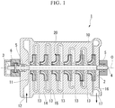
Fig. 1 is a longitudinal cross-sectional view of a rotary machine according to a first embodiment. -
Fig. 2 is a longitudinal cross-sectional view of an impeller according to the first embodiment. -
Fig. 3 is a schematic view showing a shape of a blade when the impeller according to the first embodiment is viewed in a direction of an axis. -
Fig. 4 is a schematic view showing the shape of the blade when the impeller according to the first embodiment is viewed in the direction of the axis, and the diagram shows an action of the impeller. -
Fig. 5 is a schematic view showing a shape of a blade when an impeller according to a second embodiment is viewed in the direction of the axis. -
Fig. 6 is a longitudinal cross-sectional view of an impeller according to a third embodiment. - Hereinafter, a compressor (rotary machine) including an impeller according to the present invention will be described with reference to
Figs. 1 to 5 . - As shown in
Fig. 1 , acompressor 1 includes arotary shaft 2,journal bearings 5, a thrust bearing 6,impellers 20, and acasing 10. Thecompressor 1 of the present embodiment is a so-called single-shaft multi-stage compressor including a plurality of stages of theimpellers 20. - The
rotary shaft 2 has a columnar shape extending in a direction of an axis O laid in the horizontal direction. Therotary shaft 2 is rotatably supported by thejournal bearings 5 around the axis O on afirst end portion 3 side (one side in the direction of the axis O) and a second end portion 4 side (the other side in the direction of the axis O) in the direction of the axis O. In therotary shaft 2, thefirst end portion 3 is supported by the thrust bearing 6. - The
impellers 20 are externally fitted to an outer circumferential surface of therotary shaft 2 and are provided in a plurality of stages at intervals in the direction of the axis O. Theseimpellers 20 rotate around the axis O together with therotary shaft 2 and perform pressure-feeding of a gas (fluid) flowing in the direction of the axis O toward the outer side in a radial direction. A detailed structure of theimpeller 20 will be described below. - The
casing 10 is a member formed to have a tubular shape and accommodates therotary shaft 2, theimpellers 20, thejournal bearings 5, and the like. Thecasing 10 rotatably supports therotary shaft 2 via thejournal bearings 5. Accordingly, theimpellers 20 attached to therotary shaft 2 can relatively rotate with respect to thecasing 10. - The
casing 10 has anintroduction channel 11,connection channels 13, and adischarge flow channel 16. - The
introduction channel 11 causes a gas to be introduced from the outside of thecasing 10 to theimpeller 20 in the foremost stage disposed farthest to one side in the plurality ofimpellers 20 in the direction of the axis O. Theintroduction channel 11 opens on the outer circumferential surface of thecasing 10. The opening serves as aninlet port 12 for a gas. Theintroduction channel 11 is connected to one side of theimpeller 20 in the foremost stage in the direction of the axis O in a part on the inner side in the radial direction. - The
connection channel 13 is a flow channel connecting a pair of impellers adjacent to each other in the direction of the axis O. Theconnection channels 13 cause a gas discharged to the outer side in the radial direction from theimpellers 20 on the front stage side to be introduced to theimpellers 20 on the rear stage side from one side in the direction of the axis O. Theconnection channel 13 has adiffuser channel 14 and areturn channel 15. - The
diffuser channels 14 are connected to the outer side of theimpellers 20 in the radial direction. Thediffuser channels 14 convert speed energy into pressure energy while causing a gas discharged from theimpellers 20 to the outer side in the radial direction to be introduced to the outer side in the radial direction. Thereturn channels 15 are connected to the outer side of thediffuser channels 14 in the radial direction. Thereturn channels 15 cause a gas toward the outer side in the radial direction to turn to the inner side in the radial direction and guide the gas to theimpellers 20 on the rear stage side. - The
discharge flow channel 16 causes a gas discharged to the outer side in the radial direction from theimpeller 20 in the rearmost stage disposed farthest to the other side in the plurality ofimpellers 20 in the direction of the axis O to be discharged to the outside of thecasing 10. Thedischarge flow channel 16 opens on the outer circumferential surface of thecasing 10. The opening serves as adischarge port 17 for a gas. Thedischarge flow channel 16 is connected to the outer side of theimpeller 20 in the rearmost stage in the radial direction in a part on the inner side in the radial direction. - Next, with reference to
Figs. 2 and3 , a detailed constitution of theimpeller 20 will be described. Theimpeller 20 has adisk 30,blades 40, and acover 36. - The
disk 30 is formed to have a disk shape about the axis O. A throughhole 31 having a circular shape about the axis O and penetrating thedisk 30 the direction of the axis O is formed in thedisk 30. An inner surface of the throughhole 31 is fitted to the outer circumferential surface of therotary shaft 2, so that theimpeller 20 is integrally fixed to therotary shaft 2. - A surface of the
disk 30 toward the other side in the direction of the axis O is a diskrear surface 32 having a flat surface shape orthogonal to the axis O. A diskmain surface 33, which gradually extends toward the outer side in the radial direction as it goes from one side toward the other side in the direction of the axis, is formed from an end portion of the throughhole 31 in thedisk 30 on one side in the direction of the axis O to an end portion of the diskrear surface 32 on the outer side in the radial direction. A part of the diskmain surface 33 on one side in the direction of the axis O is directed to the outer side in the radial direction. The diskmain surface 33 is gradually curved toward one side in the direction of the axis O as it goes toward the other side in the direction of the axis O. That is, the diskmain surface 33 is gradually increased in diameter as it goes from one side toward the other side in the direction of the axis O. The diskmain surface 33 has a recessed curve surface shape. - In the present embodiment, a disk
front end surface 34 having a flat surface shape orthogonal to the direction of the axis O is formed between an end portion of the diskmain surface 33 on one side in the direction of the axis O and the end portion of the throughhole 31 on one side in the direction of the axis O. A diskouter end surface 35 extending in the direction of the axis O and becoming an outer circumferential edge portion of thedisk 30 is provided between the end portion of the diskmain surface 33 on the other side in the direction of the axis O and the end portion of the diskrear surface 32 on the outer side in the radial direction. - A plurality of
blades 40 are provided at intervals in a circumferential direction of the axis O on the diskmain surface 33 in thedisk 30. Each of theblades 40 is curved toward the rear side in a rotation direction R (one side in the circumferential direction) of theimpellers 20 as it goes from the inner side in the radial direction toward the outer side in the radial direction. Each of theblades 40 extends while having a projected curve surface projected toward the front side in the rotation direction R. - The
cover 36 covers the plurality ofblades 40 from one side in the direction of the axis O. Thecover 36 is provided to face thedisk 30 such that theblades 40 are interposed between thecover 36 and thedisk 30. An innercircumferential surface 37 of thecover 36 is formed to be gradually increased in diameter as it goes from one side toward the other side in the direction of the axis O. The innercircumferential surface 37 of thecover 36 is curved in a manner similar to that of the diskmain surface 33 to correspond to the diskmain surface 33. End portions of theblades 40 on a side opposite to the diskmain surface 33 side are fixed to the innercircumferential surface 37 of thecover 36. - A flow channel extending to curve to the rear side in the rotation direction R as it goes from one side toward the other side in the direction of the axis O is formed between and by the inner
circumferential surface 37 of thecover 36, the diskmain surface 33, and theblades 40. - Here, in the present embodiment, each of the
blades 40 is constituted ofprimary blades 50 andsecondary blades 60 respectively corresponding to theprimary blades 50. - The
primary blade 50 has a blade shape extending to the rear side in the rotation direction R as it goes from the inner side toward the outer side in the radial direction. Afront edge 51 of theprimary blades 50 are disposed at positions close to an end portion of thecover 36 on one side in the direction of the axis O. Rear edges 52 of theprimary blades 50 are positioned on the inner side of the outer circumferential edge portion of thedisk 30 in the radial direction. That is, therear edges 52 of theprimary blades 50 do not lead to the outer circumferential edge portion of thedisk 30 and are disposed at intervals with respect to the outer circumferential end portion on the inner side of the outer circumferential edge portion in the radial direction. - A surface of the
primary blade 50 toward the front side in the rotation direction R (the other side in the circumferential direction) serves as apressure surface 53, and a surface toward the rear side in the rotation direction R serves as asuction surface 54. - The
secondary blades 60 are provided at intervals on a rear edge side of the correspondingprimary blades 50 and the front side in the rotation direction R. Thesecondary blade 60 has a blade shape extending to the rear side in the rotation direction R as it goes from the inner side toward the outer side in the radial direction. Afront edge 61 of thesecondary blade 60 is positioned on the outer side of thefront edge 51 of theprimary blade 50 in the radial direction. Arear edge 62 of thesecondary blade 60 leads to the outer circumferential edge portion of thedisk 30. - A surface of the
secondary blade 60 toward the front side in the rotation direction R (the other side in the circumferential direction) serves as apressure surface 63. A surface toward the rear side in the rotation direction R serves as asuction surface 64. - The
secondary blade 60 is positioned on a curved line realized by smoothly extending an imaginary curved line of theprimary blade 50 from therear edge 62 to the outer circumferential edge portion while being shifted as it stands to a side to which thepressure surface 53 of theprimary blade 50 is directed. Thefront edge 61 of thesecondary blade 60 is disposed on the upstream side of a flow of a gas along thepressure surface 53 of theprimary blade 50 from therear edge 52 of theprimary blade 50 and at a position separated from theprimary blade 50 in a direction in which thepressure surface 53 of theprimary blade 50 is directed. - Here, a rear
edge side region 53a which is a part including therear edge 52 on thepressure surface 53 in theprimary blade 50, and a frontedge side region 64a which is a part including thefront edge 61 on thesuction surface 64 in thesecondary blade 60 face each other. Accordingly, the rearedge side region 53a of theprimary blade 50 and the frontedge side region 64a of thesecondary blade 60 overlap each other in a direction orthogonal to a flowing direction of a gas along thepressure surface 53 of theprimary blade 50. In other words, parts of theprimary blade 50 and thesecondary blade 60 overlapping each other in a direction orthogonal to the flowing direction of a gas serve as the rearedge side region 53a of theprimary blade 50 and the frontedge side region 64a of thesecondary blade 60. In this manner, due to the rearedge side region 53a of theprimary blade 50 and the frontedge side region 64a of thesecondary blade 60 facing each other, a peelingcutting flow channel 70 for cutting off peeling from a gas flowing between theprimary blades 50 is formed between the rearedge side region 53a and the frontedge side region 64a. The peelingcutting flow channel 70 may be increased or decreased as the width viewed in the direction of the axis O goes toward the downstream side. - The chord length of the secondary blade 60 (length of a line segment connecting the
front edge 61 and therear edge 62 of thesecondary blade 60 when viewed in the direction of the axis O) is preferably set to the length within a range of 5% to 30% and is more preferably set to the length within a range of 5% to 20% of the chord length of the primary blade 50 (length of a line segment connecting thefront edge 51 and therear edge 52 of theprimary blade 50 when viewed in the direction of the axis O). - Here, an angle formed by line segments respectively connecting the
rear edges 52 of the adjacentprimary blades 50 and the axis O viewed in the direction of the axis O is referred to as θ1. In addition, an angle formed by the line segment connecting therear edge 52 of theprimary blade 40 and the axis O and a line segment connecting thefront edge 61 of thesecondary blade 60 corresponding to theprimary blade 50 and the axis O viewed in the direction of the axis O is referred to as θ2. At this time, in the present embodiment, it is preferable that θ2/θ1≤0.1 be established. - In other words, the angle θ1 is an angle formed by a straight line passing through the axis O and the
rear edge 52 of theprimary blade 50 on the front side in the rotation direction R of theprimary blades 50 adjacent to each other, and a straight line passing through the axis O and therear edge 52 of theprimary blade 50 on the rear side in the rotation direction R of theprimary blades 50 adjacent to each other. On the other hand, the angle θ2 is an angle formed by a straight line passing through the axis O and thefront edge 61 of thesecondary blade 60, and a straight line passing through the axis O and therear edge 2 of thesecondary blade 60. - It is preferable that the
rear edge 52 of the correspondingprimary blade 50 be positioned within the range of the angle θ2 of thesecondary blade 60 corresponding to theprimary blade 50. - It is preferable that the
secondary blade 60 corresponding to theprimary blade 50 be disposed closer to the correspondingprimary blade 50 than theprimary blade 50 positioned on a side in front of theprimary blade 50 in the rotation direction R. - The foregoing
impellers 20 may be produced using a 3D printer, for example. - Next, operational effects of the
impellers 20 and thecompressor 1 of the present embodiment will be described. - When the
impellers 20 rotates in accordance with rotation of therotary shaft 2, a gas is introduced to the flow channels inside theimpellers 20 from one side in the direction of the axis O. In this manner, during a process toward the outer side in the radial direction inside the flow channel, energy from the pressure surfaces 53 of theprimary blades 50 is applied to a gas which has been introduced into theimpellers 20, and the gas is boosted. - Here, inside the flow channels of the
impellers 20, as shown inFig. 4 , as it goes toward the downstream side (outer side in the radial direction), border layers B grow on the pressure surfaces 53 of theprimary blades 50 due to the influence of the viscosity of the pressure surfaces 53 of theprimary blades 50. In the present embodiment, the border layers B which have grown in this manner move forward along the pressure surfaces 53 of theprimary blades 50 inside the peelingcutting flow channels 70 formed between the pressure surfaces 53 and the suction surfaces 64 of thesecondary blades 60. That is, the border layers B are cut off in regions between therear edges 52 of theprimary blades 50 and thefront edges 61 of thesecondary blades 60. - On the other hand, the pressure surfaces 63 of the
secondary blades 60 apply energy to flows which are less affected by the border layers B and are separated from thepressure surface 53 of theprimary blade 50 to the front side in the rotation direction R or flows which are not affected by the border layers B, and the flows are boosted. - In this manner, in the present embodiment, the border layers B in flows between the
primary blades 50 and thesecondary blades 60 are temporarily reset. If the border layers B are not reset, peeling may occur by being further boosted thereafter. In the present embodiment, the border layers B which have grown in theprimary blades 50 are cut off in the middle of the process, so that a gas can be further boosted thereafter by thesecondary blades 60. That is, since lift can be effectively obtained by thesecondary blades 60 without causing peeling, greater lift can be obtained in theimpellers 20 overall. - The cut border layers B merge with flows near the suction surfaces 54 of the
primary blades 50. Accordingly, energy can be supplied to places near the suction surfaces 54, and therefore it is possible to obtain an effect of preventing peeling near thesuction surface 54. - In addition, if the
rear edges 52 of theprimary blades 50 have led to the outer circumferential edge portion of thedisk 30, there is a possibility that the border layers B may peel off due to theprimary blades 50. However, since theprimary blades 50 do not lead to the outer circumferential end portion, no peeling occurs. - In addition, in the present embodiment, the rear
edge side region 53a on thepressure surface 53 of theprimary blade 50 and the frontedge side region 64a on thesuction surface 64 of thesecondary blade 60 overlap each other in a direction orthogonal to a flow of a fluid, and the peelingcutting flow channel 70 is formed therebetween. Therefore, the border layers B which have grown on the pressure surfaces 53 of theprimary blades 50 are caused to be cut off by thefront edges 61 of thesecondary blades 60 and are transferred to the outer side in the radial direction as they stand along the pressure surfaces 53 of theprimary blades 50. Therefore, the border layers B can be more reliably cut off by flows between theprimary blades 50. - Moreover, since the
secondary blade 60 is disposed close to the correspondingprimary blade 50 side of a pair ofprimary blades 50 adjacent to each other, the border layer B which has grown on thepressure surface 53 of the correspondingprimary blade 50 can be more reliably cut off by thesecondary blade 60. It is preferable that the separation distance from the correspondingprimary blade 50 to thefront edge 61 of thesecondary blade 60 be equivalent to or larger than the thickness of the border layer B which has developed on thepressure surface 53 of theprimary blade 50 at a position of thefront edge 61 of thesecondary blade 60. - Here, if the chord length of the
secondary blade 60 is excessively long, the pressure surfaces 53 of theprimary blades 50 are hindered from supplying energy to flows. In addition, if the chord length of thesecondary blade 60 is excessively short, the supply amount of energy of thepressure surface 63 of thesecondary blade 60 with respect to a flow after the border layer B is cut off is reduced. - In the present embodiment, since the chord length of the
secondary blade 60 is set to a range of 5% to 30% of the chord length of theprimary blade 50, energy supplied to a gas by theprimary blades 50 and thesecondary blades 60 can be optimized. - In addition, since a relationship of θ2/θ1≤0.1 is established between the angle θ1 and the angle θ2, as previously stated, operational effects of the
primary blades 50 and thesecondary blades 60 can be further enhanced. - Next, a second embodiment of the present invention will be described with reference to
Fig. 5 . In the second embodiment, the same reference signs are applied to the same constituent elements as the first embodiment, and a detailed description thereof will be omitted. - An
impeller 20A of the second embodiment differs from the first embodiment in constitution ofsecondary blades 80. Thesecondary blade 80 of the second embodiment is constituted of a plurality of stages ofsecondary blade pieces 81. - The plurality of stages of
secondary blade pieces 81 are sequentially arranged at intervals toward the outer side in the radial direction. In the present embodiment, thesecondary blade 80 is constituted of thesecondary blade pieces 81 in two stages. Each of thesecondary blade pieces 81 has a blade shape extending to the rear side in the rotation direction R as it goes toward the outer side in the radial direction. In each of thesecondary blade pieces 81, a surface toward the front side in the rotation direction R serves as a pressure surface, and a surface toward the rear side in the rotation direction R serves as a suction surface. - The front edge of the
secondary blade piece 81 in the front stage (front edge of the secondary blade 80) is disposed on the upstream side of a flow of a gas along thepressure surface 53 of theprimary blade 50 from therear edge 52 of theprimary blade 50 to be separated in a direction in which thepressure surface 53 of theprimary blade 50 is directed. The rear edge of thesecondary blade piece 81 in the front stage is separated from the outer circumferential edge portion of thedisk 30 to the inner side in the radial direction. - The front edge of the
secondary blade piece 81 in the rear stage is disposed on the upstream side of a flow of a gas along the pressure surface of thesecondary blade piece 81 in the front stage from the rear edge of thesecondary blade piece 81 in the front stage to be separated in a direction in which the pressure surface of thesecondary blade piece 81 in the front stage is directed. The rear edge of thesecondary blade piece 81 in the rear stage leads to the outer circumferential edge portion of thedisk 30. - According to the
impellers 20A of the second embodiment, the border layers B which have grown on the pressure surfaces 53 of theprimary blades 50 are cut off between thesecondary blade pieces 81 in the front stages. In addition, the border layers B which have grown on the pressure surfaces of thesecondary blade pieces 81 in the front stages are cut off between thesecondary blade pieces 81 in the rear stages. Therefore, since the border layers B can be sequentially reset as they go toward the downstream side, lift can be more effectively obtained by the entiresecondary blades 80. - The second embodiment may have three or more
secondary blade pieces 81. In this case, the relationship betweensecondary blade pieces 81 adjacent to each other is similar to the relationship between thesecondary blade piece 81 in the front stage and thesecondary blade piece 81 in the rear stage. In addition, the rear edge of thesecondary blade piece 81 in the rearmost stage is positioned in the outer circumferential edge portion of thedisk 30. - Next, a third embodiment of the present invention will be described with reference to
Fig. 6 . In the third embodiment, the same reference signs are applied to the same constituent elements as the first embodiment, and detailed description thereof will be omitted. - In an
impeller 20B of the third embodiment, a pair ofsecondary blades 90a and 90b are provided to correspond to theprimary blade 50 while being separated from each other on thedisk 30 side and thecover 36 side. - That is, in a cross-sectional view including the axis O, when the flow channel is divided into three regions including a
disk side region 91, acover side region 92, and acentral region 93, thesecondary blades 90a and 90b are provided in only thedisk side region 91 and thecover side region 92 and are not provided in thecentral region 93. - Accordingly, a total pressure distribution in which the total pressure near the wall surface in the direction of the axis O rises is realized inside the
diffuser channels 14. Therefore, peeling in thediffuser channels 14 is curbed, and significant pressure recovery in thediffuser channels 14 can be expected. As a result, thecompressor 1 in its entirety can have a compact size, and the number of stages can be reduced. - In the third embodiment, for example, a secondary blade may be provided in only the
disk side region 91, or thesecondary blades 90a and 90b may be provided in only thecover side region 92. Accordingly, as previously stated, peeling at any place in thediffuser channels 14 in the direction of the axis O can be curbed. - Hereinabove, embodiments of the present invention have been described. However, the present invention is not limited thereto and can be suitably changed within a range not departing from the technical idea of the invention.
- In the embodiments, each of the
impellers cover 36. However, the present invention may be applied to an open impeller which does not include thecover 30. - In the embodiments, the
compressor 1 has been described as an example of a rotary machine. However, for example, the present invention may also be applied to other rotary machines such as pumps. - According to an impeller and a rotary machine of the present invention, greater lift can be obtained.
-
- 1 Compressor
- 2 Rotary shaft
- 3 First end portion
- 4 Second end portion
- 5 Journal bearing
- 6 Thrust bearing
- 10 Casing
- 11 Introduction channel
- 12 Inlet port
- 13 Connection channel
- 14 Diffuser channel
- 15 Return channel
- 16 Discharge flow channel
- 17 Discharge port
- 20 Impeller
- 30 Disk
- 31 Through hole
- 32 Disk rear surface
- 33 Disk main surface
- 34 Disk front end surface
- 35 Disk outer end surface
- 36 Cover
- 37 Inner circumferential surface
- 40 Blade
- 50 Primary blade
- 51 Front edge
- 52 Rear edge
- 53 Pressure surface
- 53a Rear edge side region
- 54 Suction surface
- 60 Secondary blade
- 61 Front edge
- 62 Rear edge
- 63 Pressure surface
- 64 Suction surface
- 64a Front edge side region
- 70 Peeling cutting flow channel
- 80 Secondary blade
- 81 Secondary blade pieces
- 90a Secondary blade
- 90b Secondary blade
- 91 Disk side region
- 92 Cover side region
- 93 Central region
- B Border layer
- O Axis
- R Rotation direction
Claims (8)
- An impeller comprising:a disk that has a disk shape and is configured to rotate around an axis; anda plurality of blades that are provided at intervals in a circumferential direction on a side of a surface of the disk toward a direction of the axis and extend to a rear side in a rotation direction as the plurality of the blades go toward an outer side in a radial direction,wherein each of the plurality of the blades has:a primary blade which extends to the rear side in the rotation direction as the primary blade goes from an inner side toward the outer side in the radial direction and of which a rear edge is positioned on the inner side with respect to an outer circumferential edge portion of the disk in the radial direction, anda secondary blade which is provided at intervals on a side in front of the primary blade in the rotation direction to correspond to the primary blade, of which a front edge is positioned on the outer side with respect to a front edge of the primary blade in the radial direction, and of which a rear edge is positioned on the outer circumferential edge portion of the disk.
- The impeller according to claim 1,
wherein a rear edge side region on a pressure surface of the primary blade and a front edge side region on a suction surface of the secondary blade corresponding to the primary blade face each other. - The impeller according to claim 1 or 2,
wherein the secondary blade is disposed close to the corresponding primary blade of a pair of primary blades adjacent to each other. - The impeller according to any one of claims 1 to 3,
wherein the secondary blade has a plurality of stages of secondary blade pieces sequentially arranged toward the outer side in the radial direction, and a front edge of the secondary blade piece on a rear stage side of adjacent secondary blade pieces is positioned on a side in front of a rear edge of the secondary blade piece on a front stage side in the rotation direction. - The impeller according to any one of claims 1 to 4, further comprising:a cover that covers the plurality of blades in the direction of the axis,wherein when a region between the disk and the cover facing each other in the direction of the axis is divided into a disk side region, a cover side region, and a central region between the disk side region and the cover side region, the secondary blade is not provided in the central region but is provided in at least one of the disk side region and the cover side region.
- The impeller according to any one of claims 1 to 5,
wherein a chord length of the secondary blade is within a range of 5% to 30% of a chord length of the primary blade. - The impeller according to any one of claims 1 to 6,
wherein when an angle formed by line segments respectively connecting the rear edges of the adjacent primary blades and the axis viewed in the direction of the axis is θ1, and when an angle formed by the line segment connecting the rear edge of the primary blade and the axis and a line segment connecting the front edge of the secondary blade corresponding to the primary blade and the axis viewed in the direction of the axis is θ2, θ2/θ1≤0.1 is established. - A rotary machine comprising:
the impeller according to any one of claims 1 to 7.
Applications Claiming Priority (2)
| Application Number | Priority Date | Filing Date | Title |
|---|---|---|---|
| JP2017036700A JP6951087B2 (en) | 2017-02-28 | 2017-02-28 | Rotating machine |
| PCT/JP2018/006413 WO2018159439A1 (en) | 2017-02-28 | 2018-02-22 | Impeller and rotary machine |
Publications (3)
| Publication Number | Publication Date |
|---|---|
| EP3591235A1 true EP3591235A1 (en) | 2020-01-08 |
| EP3591235A4 EP3591235A4 (en) | 2020-02-26 |
| EP3591235B1 EP3591235B1 (en) | 2021-02-17 |
Family
ID=63371101
Family Applications (1)
| Application Number | Title | Priority Date | Filing Date |
|---|---|---|---|
| EP18761771.7A Active EP3591235B1 (en) | 2017-02-28 | 2018-02-22 | Impeller and rotary machine |
Country Status (4)
| Country | Link |
|---|---|
| US (1) | US11053952B2 (en) |
| EP (1) | EP3591235B1 (en) |
| JP (1) | JP6951087B2 (en) |
| WO (1) | WO2018159439A1 (en) |
Families Citing this family (4)
| Publication number | Priority date | Publication date | Assignee | Title |
|---|---|---|---|---|
| WO2021072148A1 (en) * | 2019-10-09 | 2021-04-15 | Heat X, LLC | Magnetic induction furnace, cooler or magnetocaloric fluid heat pump with varied conductive plate configurations |
| CN112360763B (en) * | 2020-09-22 | 2023-01-24 | 东风汽车集团有限公司 | Turbocharger |
| CN121889582A (en) * | 2023-07-21 | 2026-04-17 | 亨利·K·欧伯梅尔 | Multi-vane row of impeller stage and diffuser stage |
| CN117249091A (en) * | 2023-11-07 | 2023-12-19 | 浙江神能科技股份有限公司 | A large-lift multi-stage centrifugal pump |
Family Cites Families (22)
| Publication number | Priority date | Publication date | Assignee | Title |
|---|---|---|---|---|
| US1383354A (en) * | 1921-02-17 | 1921-07-05 | Wareing James | Impeller for centrifugal pumps |
| GB180299A (en) * | 1921-05-14 | 1922-10-26 | Bbc Brown Boveri & Cie | Improvements in rotors for centrifugal compressors |
| FR892480A (en) * | 1942-02-21 | 1944-04-07 | Sulzer Ag | Very high pressure compressor |
| US2576700A (en) * | 1947-06-02 | 1951-11-27 | Schneider Brothers Company | Blading for fluid flow devices |
| US2753808A (en) * | 1950-02-15 | 1956-07-10 | Kluge Dorothea | Centrifugal impeller |
| US3221662A (en) * | 1963-02-14 | 1965-12-07 | American Radiator & Standard | Method and apparatus for controlling flow in centrifugal machines |
| JPS52144803A (en) * | 1976-05-27 | 1977-12-02 | Kubota Ltd | Preparation of high lift impeller wheel |
| JPS5457603U (en) * | 1977-09-30 | 1979-04-20 | ||
| JPS5879094U (en) * | 1981-11-25 | 1983-05-28 | 株式会社荏原製作所 | centrifugal compressor |
| US4502837A (en) | 1982-09-30 | 1985-03-05 | General Electric Company | Multi stage centrifugal impeller |
| JPS59190498A (en) * | 1983-04-11 | 1984-10-29 | Gadelius Kk | Vane for centrifugal blower |
| US4615659A (en) * | 1983-10-24 | 1986-10-07 | Sundstrand Corporation | Offset centrifugal compressor |
| JPS62291498A (en) * | 1986-06-12 | 1987-12-18 | Mitsubishi Heavy Ind Ltd | Impeller |
| JPH0212096U (en) * | 1988-07-07 | 1990-01-25 | ||
| JP2533175B2 (en) * | 1988-11-22 | 1996-09-11 | 松下電器産業株式会社 | Electric blower |
| JP2961686B2 (en) | 1996-05-20 | 1999-10-12 | 株式会社荻原製作所 | Centrifugal pump |
| JP2002349487A (en) * | 2001-05-28 | 2002-12-04 | Mitsubishi Heavy Ind Ltd | Impeller and centrifugal compressor |
| US6676366B2 (en) * | 2002-03-05 | 2004-01-13 | Baker Hughes Incorporated | Submersible pump impeller design for lifting gaseous fluid |
| TWI311611B (en) * | 2006-08-25 | 2009-07-01 | Ind Tech Res Inst | Impeller structure and the centrifugal fan device using the same |
| JP6350444B2 (en) | 2015-08-10 | 2018-07-04 | トヨタ自動車株式会社 | Exhaust gas purification device for internal combustion engine |
| CN205383109U (en) * | 2016-02-29 | 2016-07-13 | 珠海格力电器股份有限公司 | Centrifugal fan and air conditioner |
| JP6990026B2 (en) * | 2017-02-16 | 2022-01-12 | シャープ株式会社 | How to manufacture electric blowers, vacuum cleaners, and impellers |
-
2017
- 2017-02-28 JP JP2017036700A patent/JP6951087B2/en active Active
-
2018
- 2018-02-22 EP EP18761771.7A patent/EP3591235B1/en active Active
- 2018-02-22 WO PCT/JP2018/006413 patent/WO2018159439A1/en not_active Ceased
- 2018-02-22 US US16/488,351 patent/US11053952B2/en active Active
Also Published As
| Publication number | Publication date |
|---|---|
| JP6951087B2 (en) | 2021-10-20 |
| EP3591235A4 (en) | 2020-02-26 |
| WO2018159439A1 (en) | 2018-09-07 |
| EP3591235B1 (en) | 2021-02-17 |
| US20200232474A1 (en) | 2020-07-23 |
| US11053952B2 (en) | 2021-07-06 |
| JP2018141422A (en) | 2018-09-13 |
Similar Documents
| Publication | Publication Date | Title |
|---|---|---|
| US11073163B2 (en) | Centrifugal compressor | |
| US10400788B2 (en) | Intermediate intake-type diaphragm and centrifugal rotating machine | |
| US11053952B2 (en) | Impeller and rotary machine | |
| EP2402616A1 (en) | Impeller and rotary machine | |
| JP7085306B2 (en) | Centrifugal compressor | |
| CN105143635B (en) | Variable nozzle unit and variable capacity booster | |
| WO2008069142A1 (en) | Centrifugal compressor | |
| US11585347B2 (en) | Mixed-flow compressor configuration for a refrigeration system | |
| JP2013147935A (en) | Centrifugal compressor | |
| US10330102B2 (en) | Centrifugal compressor and turbocharger | |
| US10450887B2 (en) | On-off valve device and rotary machine | |
| EP3705698B1 (en) | Turbine and turbocharger | |
| US11125236B2 (en) | Centrifugal compressor | |
| US10989201B2 (en) | Centrifugal compressor | |
| US20220372992A1 (en) | Rotating machinery | |
| US10871164B2 (en) | Centrifugal compressor | |
| EP2955387A1 (en) | Centrifugal compressor | |
| EP3096022A1 (en) | Impeller and rotating machine provided with same | |
| JP6331518B2 (en) | Centrifugal compressor | |
| CN107250555A (en) | Movable vane piece and axial-flow type rotating machinery | |
| JP2020186729A (en) | Centrifugal compressor |
Legal Events
| Date | Code | Title | Description |
|---|---|---|---|
| STAA | Information on the status of an ep patent application or granted ep patent |
Free format text: STATUS: THE INTERNATIONAL PUBLICATION HAS BEEN MADE |
|
| PUAI | Public reference made under article 153(3) epc to a published international application that has entered the european phase |
Free format text: ORIGINAL CODE: 0009012 |
|
| STAA | Information on the status of an ep patent application or granted ep patent |
Free format text: STATUS: REQUEST FOR EXAMINATION WAS MADE |
|
| 17P | Request for examination filed |
Effective date: 20190819 |
|
| AK | Designated contracting states |
Kind code of ref document: A1 Designated state(s): AL AT BE BG CH CY CZ DE DK EE ES FI FR GB GR HR HU IE IS IT LI LT LU LV MC MK MT NL NO PL PT RO RS SE SI SK SM TR |
|
| A4 | Supplementary search report drawn up and despatched |
Effective date: 20200124 |
|
| RIC1 | Information provided on ipc code assigned before grant |
Ipc: F04D 29/24 20060101ALI20200120BHEP Ipc: F04D 17/12 20060101ALN20200120BHEP Ipc: F04D 29/30 20060101AFI20200120BHEP Ipc: F04D 29/28 20060101ALI20200120BHEP |
|
| GRAP | Despatch of communication of intention to grant a patent |
Free format text: ORIGINAL CODE: EPIDOSNIGR1 |
|
| STAA | Information on the status of an ep patent application or granted ep patent |
Free format text: STATUS: GRANT OF PATENT IS INTENDED |
|
| RIC1 | Information provided on ipc code assigned before grant |
Ipc: F04D 29/28 20060101ALI20200818BHEP Ipc: F04D 29/30 20060101AFI20200818BHEP Ipc: F04D 17/12 20060101ALN20200818BHEP Ipc: F04D 29/24 20060101ALI20200818BHEP |
|
| RIC1 | Information provided on ipc code assigned before grant |
Ipc: F04D 17/12 20060101ALN20200824BHEP Ipc: F04D 29/30 20060101AFI20200824BHEP Ipc: F04D 29/24 20060101ALI20200824BHEP Ipc: F04D 29/28 20060101ALI20200824BHEP |
|
| INTG | Intention to grant announced |
Effective date: 20200908 |
|
| GRAS | Grant fee paid |
Free format text: ORIGINAL CODE: EPIDOSNIGR3 |
|
| GRAA | (expected) grant |
Free format text: ORIGINAL CODE: 0009210 |
|
| STAA | Information on the status of an ep patent application or granted ep patent |
Free format text: STATUS: THE PATENT HAS BEEN GRANTED |
|
| AK | Designated contracting states |
Kind code of ref document: B1 Designated state(s): AL AT BE BG CH CY CZ DE DK EE ES FI FR GB GR HR HU IE IS IT LI LT LU LV MC MK MT NL NO PL PT RO RS SE SI SK SM TR |
|
| REG | Reference to a national code |
Ref country code: GB Ref legal event code: FG4D |
|
| REG | Reference to a national code |
Ref country code: CH Ref legal event code: EP |
|
| REG | Reference to a national code |
Ref country code: DE Ref legal event code: R096 Ref document number: 602018012767 Country of ref document: DE |
|
| REG | Reference to a national code |
Ref country code: AT Ref legal event code: REF Ref document number: 1361849 Country of ref document: AT Kind code of ref document: T Effective date: 20210315 |
|
| REG | Reference to a national code |
Ref country code: IE Ref legal event code: FG4D |
|
| REG | Reference to a national code |
Ref country code: LT Ref legal event code: MG9D |
|
| REG | Reference to a national code |
Ref country code: NL Ref legal event code: MP Effective date: 20210217 |
|
| PG25 | Lapsed in a contracting state [announced via postgrant information from national office to epo] |
Ref country code: BG Free format text: LAPSE BECAUSE OF FAILURE TO SUBMIT A TRANSLATION OF THE DESCRIPTION OR TO PAY THE FEE WITHIN THE PRESCRIBED TIME-LIMIT Effective date: 20210517 Ref country code: FI Free format text: LAPSE BECAUSE OF FAILURE TO SUBMIT A TRANSLATION OF THE DESCRIPTION OR TO PAY THE FEE WITHIN THE PRESCRIBED TIME-LIMIT Effective date: 20210217 Ref country code: GR Free format text: LAPSE BECAUSE OF FAILURE TO SUBMIT A TRANSLATION OF THE DESCRIPTION OR TO PAY THE FEE WITHIN THE PRESCRIBED TIME-LIMIT Effective date: 20210518 Ref country code: HR Free format text: LAPSE BECAUSE OF FAILURE TO SUBMIT A TRANSLATION OF THE DESCRIPTION OR TO PAY THE FEE WITHIN THE PRESCRIBED TIME-LIMIT Effective date: 20210217 Ref country code: LT Free format text: LAPSE BECAUSE OF FAILURE TO SUBMIT A TRANSLATION OF THE DESCRIPTION OR TO PAY THE FEE WITHIN THE PRESCRIBED TIME-LIMIT Effective date: 20210217 Ref country code: NO Free format text: LAPSE BECAUSE OF FAILURE TO SUBMIT A TRANSLATION OF THE DESCRIPTION OR TO PAY THE FEE WITHIN THE PRESCRIBED TIME-LIMIT Effective date: 20210517 Ref country code: PT Free format text: LAPSE BECAUSE OF FAILURE TO SUBMIT A TRANSLATION OF THE DESCRIPTION OR TO PAY THE FEE WITHIN THE PRESCRIBED TIME-LIMIT Effective date: 20210617 |
|
| REG | Reference to a national code |
Ref country code: AT Ref legal event code: MK05 Ref document number: 1361849 Country of ref document: AT Kind code of ref document: T Effective date: 20210217 |
|
| PG25 | Lapsed in a contracting state [announced via postgrant information from national office to epo] |
Ref country code: RS Free format text: LAPSE BECAUSE OF FAILURE TO SUBMIT A TRANSLATION OF THE DESCRIPTION OR TO PAY THE FEE WITHIN THE PRESCRIBED TIME-LIMIT Effective date: 20210217 Ref country code: NL Free format text: LAPSE BECAUSE OF FAILURE TO SUBMIT A TRANSLATION OF THE DESCRIPTION OR TO PAY THE FEE WITHIN THE PRESCRIBED TIME-LIMIT Effective date: 20210217 Ref country code: PL Free format text: LAPSE BECAUSE OF FAILURE TO SUBMIT A TRANSLATION OF THE DESCRIPTION OR TO PAY THE FEE WITHIN THE PRESCRIBED TIME-LIMIT Effective date: 20210217 Ref country code: LV Free format text: LAPSE BECAUSE OF FAILURE TO SUBMIT A TRANSLATION OF THE DESCRIPTION OR TO PAY THE FEE WITHIN THE PRESCRIBED TIME-LIMIT Effective date: 20210217 Ref country code: SE Free format text: LAPSE BECAUSE OF FAILURE TO SUBMIT A TRANSLATION OF THE DESCRIPTION OR TO PAY THE FEE WITHIN THE PRESCRIBED TIME-LIMIT Effective date: 20210217 |
|
| PG25 | Lapsed in a contracting state [announced via postgrant information from national office to epo] |
Ref country code: IS Free format text: LAPSE BECAUSE OF FAILURE TO SUBMIT A TRANSLATION OF THE DESCRIPTION OR TO PAY THE FEE WITHIN THE PRESCRIBED TIME-LIMIT Effective date: 20210617 |
|
| REG | Reference to a national code |
Ref country code: BE Ref legal event code: MM Effective date: 20210228 |
|
| PG25 | Lapsed in a contracting state [announced via postgrant information from national office to epo] |
Ref country code: CZ Free format text: LAPSE BECAUSE OF FAILURE TO SUBMIT A TRANSLATION OF THE DESCRIPTION OR TO PAY THE FEE WITHIN THE PRESCRIBED TIME-LIMIT Effective date: 20210217 Ref country code: EE Free format text: LAPSE BECAUSE OF FAILURE TO SUBMIT A TRANSLATION OF THE DESCRIPTION OR TO PAY THE FEE WITHIN THE PRESCRIBED TIME-LIMIT Effective date: 20210217 Ref country code: LU Free format text: LAPSE BECAUSE OF NON-PAYMENT OF DUE FEES Effective date: 20210222 Ref country code: LI Free format text: LAPSE BECAUSE OF NON-PAYMENT OF DUE FEES Effective date: 20210228 Ref country code: SM Free format text: LAPSE BECAUSE OF FAILURE TO SUBMIT A TRANSLATION OF THE DESCRIPTION OR TO PAY THE FEE WITHIN THE PRESCRIBED TIME-LIMIT Effective date: 20210217 Ref country code: AT Free format text: LAPSE BECAUSE OF FAILURE TO SUBMIT A TRANSLATION OF THE DESCRIPTION OR TO PAY THE FEE WITHIN THE PRESCRIBED TIME-LIMIT Effective date: 20210217 Ref country code: CH Free format text: LAPSE BECAUSE OF NON-PAYMENT OF DUE FEES Effective date: 20210228 |
|
| REG | Reference to a national code |
Ref country code: DE Ref legal event code: R097 Ref document number: 602018012767 Country of ref document: DE |
|
| PG25 | Lapsed in a contracting state [announced via postgrant information from national office to epo] |
Ref country code: DK Free format text: LAPSE BECAUSE OF FAILURE TO SUBMIT A TRANSLATION OF THE DESCRIPTION OR TO PAY THE FEE WITHIN THE PRESCRIBED TIME-LIMIT Effective date: 20210217 Ref country code: SK Free format text: LAPSE BECAUSE OF FAILURE TO SUBMIT A TRANSLATION OF THE DESCRIPTION OR TO PAY THE FEE WITHIN THE PRESCRIBED TIME-LIMIT Effective date: 20210217 Ref country code: RO Free format text: LAPSE BECAUSE OF FAILURE TO SUBMIT A TRANSLATION OF THE DESCRIPTION OR TO PAY THE FEE WITHIN THE PRESCRIBED TIME-LIMIT Effective date: 20210217 Ref country code: MC Free format text: LAPSE BECAUSE OF FAILURE TO SUBMIT A TRANSLATION OF THE DESCRIPTION OR TO PAY THE FEE WITHIN THE PRESCRIBED TIME-LIMIT Effective date: 20210217 |
|
| PLBE | No opposition filed within time limit |
Free format text: ORIGINAL CODE: 0009261 |
|
| STAA | Information on the status of an ep patent application or granted ep patent |
Free format text: STATUS: NO OPPOSITION FILED WITHIN TIME LIMIT |
|
| 26N | No opposition filed |
Effective date: 20211118 |
|
| PG25 | Lapsed in a contracting state [announced via postgrant information from national office to epo] |
Ref country code: AL Free format text: LAPSE BECAUSE OF FAILURE TO SUBMIT A TRANSLATION OF THE DESCRIPTION OR TO PAY THE FEE WITHIN THE PRESCRIBED TIME-LIMIT Effective date: 20210217 Ref country code: IE Free format text: LAPSE BECAUSE OF NON-PAYMENT OF DUE FEES Effective date: 20210222 Ref country code: ES Free format text: LAPSE BECAUSE OF FAILURE TO SUBMIT A TRANSLATION OF THE DESCRIPTION OR TO PAY THE FEE WITHIN THE PRESCRIBED TIME-LIMIT Effective date: 20210217 Ref country code: FR Free format text: LAPSE BECAUSE OF NON-PAYMENT OF DUE FEES Effective date: 20210417 |
|
| PG25 | Lapsed in a contracting state [announced via postgrant information from national office to epo] |
Ref country code: SI Free format text: LAPSE BECAUSE OF FAILURE TO SUBMIT A TRANSLATION OF THE DESCRIPTION OR TO PAY THE FEE WITHIN THE PRESCRIBED TIME-LIMIT Effective date: 20210217 |
|
| PG25 | Lapsed in a contracting state [announced via postgrant information from national office to epo] |
Ref country code: IS Free format text: LAPSE BECAUSE OF FAILURE TO SUBMIT A TRANSLATION OF THE DESCRIPTION OR TO PAY THE FEE WITHIN THE PRESCRIBED TIME-LIMIT Effective date: 20210617 |
|
| PG25 | Lapsed in a contracting state [announced via postgrant information from national office to epo] |
Ref country code: BE Free format text: LAPSE BECAUSE OF NON-PAYMENT OF DUE FEES Effective date: 20210228 |
|
| GBPC | Gb: european patent ceased through non-payment of renewal fee |
Effective date: 20220222 |
|
| PG25 | Lapsed in a contracting state [announced via postgrant information from national office to epo] |
Ref country code: GB Free format text: LAPSE BECAUSE OF NON-PAYMENT OF DUE FEES Effective date: 20220222 |
|
| PG25 | Lapsed in a contracting state [announced via postgrant information from national office to epo] |
Ref country code: CY Free format text: LAPSE BECAUSE OF FAILURE TO SUBMIT A TRANSLATION OF THE DESCRIPTION OR TO PAY THE FEE WITHIN THE PRESCRIBED TIME-LIMIT Effective date: 20210217 |
|
| PG25 | Lapsed in a contracting state [announced via postgrant information from national office to epo] |
Ref country code: HU Free format text: LAPSE BECAUSE OF FAILURE TO SUBMIT A TRANSLATION OF THE DESCRIPTION OR TO PAY THE FEE WITHIN THE PRESCRIBED TIME-LIMIT; INVALID AB INITIO Effective date: 20180222 |
|
| PG25 | Lapsed in a contracting state [announced via postgrant information from national office to epo] |
Ref country code: MK Free format text: LAPSE BECAUSE OF FAILURE TO SUBMIT A TRANSLATION OF THE DESCRIPTION OR TO PAY THE FEE WITHIN THE PRESCRIBED TIME-LIMIT Effective date: 20210217 |
|
| PGFP | Annual fee paid to national office [announced via postgrant information from national office to epo] |
Ref country code: IT Payment date: 20240111 Year of fee payment: 7 |
|
| PG25 | Lapsed in a contracting state [announced via postgrant information from national office to epo] |
Ref country code: TR Free format text: LAPSE BECAUSE OF FAILURE TO SUBMIT A TRANSLATION OF THE DESCRIPTION OR TO PAY THE FEE WITHIN THE PRESCRIBED TIME-LIMIT Effective date: 20210217 |
|
| PG25 | Lapsed in a contracting state [announced via postgrant information from national office to epo] |
Ref country code: MT Free format text: LAPSE BECAUSE OF FAILURE TO SUBMIT A TRANSLATION OF THE DESCRIPTION OR TO PAY THE FEE WITHIN THE PRESCRIBED TIME-LIMIT Effective date: 20210217 |
|
| PGFP | Annual fee paid to national office [announced via postgrant information from national office to epo] |
Ref country code: DE Payment date: 20241231 Year of fee payment: 8 |
|
| PG25 | Lapsed in a contracting state [announced via postgrant information from national office to epo] |
Ref country code: IT Free format text: LAPSE BECAUSE OF NON-PAYMENT OF DUE FEES Effective date: 20250222 |