EP3591211A2 - Work vehicle - Google Patents
Work vehicle Download PDFInfo
- Publication number
- EP3591211A2 EP3591211A2 EP19175231.0A EP19175231A EP3591211A2 EP 3591211 A2 EP3591211 A2 EP 3591211A2 EP 19175231 A EP19175231 A EP 19175231A EP 3591211 A2 EP3591211 A2 EP 3591211A2
- Authority
- EP
- European Patent Office
- Prior art keywords
- engine
- air cleaner
- work vehicle
- air
- hood
- Prior art date
- Legal status (The legal status is an assumption and is not a legal conclusion. Google has not performed a legal analysis and makes no representation as to the accuracy of the status listed.)
- Granted
Links
Images




Classifications
-
- F—MECHANICAL ENGINEERING; LIGHTING; HEATING; WEAPONS; BLASTING
- F02—COMBUSTION ENGINES; HOT-GAS OR COMBUSTION-PRODUCT ENGINE PLANTS
- F02M—SUPPLYING COMBUSTION ENGINES IN GENERAL WITH COMBUSTIBLE MIXTURES OR CONSTITUENTS THEREOF
- F02M35/00—Combustion-air cleaners, air intakes, intake silencers, or induction systems specially adapted for, or arranged on, internal-combustion engines
- F02M35/10—Air intakes; Induction systems
- F02M35/10006—Air intakes; Induction systems characterised by the position of elements of the air intake system in direction of the air intake flow, i.e. between ambient air inlet and supply to the combustion chamber
-
- F—MECHANICAL ENGINEERING; LIGHTING; HEATING; WEAPONS; BLASTING
- F02—COMBUSTION ENGINES; HOT-GAS OR COMBUSTION-PRODUCT ENGINE PLANTS
- F02M—SUPPLYING COMBUSTION ENGINES IN GENERAL WITH COMBUSTIBLE MIXTURES OR CONSTITUENTS THEREOF
- F02M35/00—Combustion-air cleaners, air intakes, intake silencers, or induction systems specially adapted for, or arranged on, internal-combustion engines
- F02M35/10—Air intakes; Induction systems
- F02M35/10006—Air intakes; Induction systems characterised by the position of elements of the air intake system in direction of the air intake flow, i.e. between ambient air inlet and supply to the combustion chamber
- F02M35/10019—Means upstream of the fuel injection system, carburettor or plenum chamber
-
- F—MECHANICAL ENGINEERING; LIGHTING; HEATING; WEAPONS; BLASTING
- F02—COMBUSTION ENGINES; HOT-GAS OR COMBUSTION-PRODUCT ENGINE PLANTS
- F02M—SUPPLYING COMBUSTION ENGINES IN GENERAL WITH COMBUSTIBLE MIXTURES OR CONSTITUENTS THEREOF
- F02M35/00—Combustion-air cleaners, air intakes, intake silencers, or induction systems specially adapted for, or arranged on, internal-combustion engines
- F02M35/10—Air intakes; Induction systems
- F02M35/10091—Air intakes; Induction systems characterised by details of intake ducts: shapes; connections; arrangements
-
- F—MECHANICAL ENGINEERING; LIGHTING; HEATING; WEAPONS; BLASTING
- F02—COMBUSTION ENGINES; HOT-GAS OR COMBUSTION-PRODUCT ENGINE PLANTS
- F02M—SUPPLYING COMBUSTION ENGINES IN GENERAL WITH COMBUSTIBLE MIXTURES OR CONSTITUENTS THEREOF
- F02M35/00—Combustion-air cleaners, air intakes, intake silencers, or induction systems specially adapted for, or arranged on, internal-combustion engines
- F02M35/16—Combustion-air cleaners, air intakes, intake silencers, or induction systems specially adapted for, or arranged on, internal-combustion engines characterised by use in vehicles
- F02M35/161—Arrangement of the air intake system in the engine compartment, e.g. with respect to the bonnet or the vehicle front face
-
- F—MECHANICAL ENGINEERING; LIGHTING; HEATING; WEAPONS; BLASTING
- F02—COMBUSTION ENGINES; HOT-GAS OR COMBUSTION-PRODUCT ENGINE PLANTS
- F02M—SUPPLYING COMBUSTION ENGINES IN GENERAL WITH COMBUSTIBLE MIXTURES OR CONSTITUENTS THEREOF
- F02M35/00—Combustion-air cleaners, air intakes, intake silencers, or induction systems specially adapted for, or arranged on, internal-combustion engines
- F02M35/16—Combustion-air cleaners, air intakes, intake silencers, or induction systems specially adapted for, or arranged on, internal-combustion engines characterised by use in vehicles
- F02M35/164—Heavy duty vehicles, e.g. trucks, trains, agricultural or construction machines
-
- F—MECHANICAL ENGINEERING; LIGHTING; HEATING; WEAPONS; BLASTING
- F02—COMBUSTION ENGINES; HOT-GAS OR COMBUSTION-PRODUCT ENGINE PLANTS
- F02M—SUPPLYING COMBUSTION ENGINES IN GENERAL WITH COMBUSTIBLE MIXTURES OR CONSTITUENTS THEREOF
- F02M35/00—Combustion-air cleaners, air intakes, intake silencers, or induction systems specially adapted for, or arranged on, internal-combustion engines
- F02M35/10—Air intakes; Induction systems
- F02M35/10006—Air intakes; Induction systems characterised by the position of elements of the air intake system in direction of the air intake flow, i.e. between ambient air inlet and supply to the combustion chamber
- F02M35/10013—Means upstream of the air filter; Connection to the ambient air
-
- F—MECHANICAL ENGINEERING; LIGHTING; HEATING; WEAPONS; BLASTING
- F02—COMBUSTION ENGINES; HOT-GAS OR COMBUSTION-PRODUCT ENGINE PLANTS
- F02M—SUPPLYING COMBUSTION ENGINES IN GENERAL WITH COMBUSTIBLE MIXTURES OR CONSTITUENTS THEREOF
- F02M35/00—Combustion-air cleaners, air intakes, intake silencers, or induction systems specially adapted for, or arranged on, internal-combustion engines
- F02M35/12—Intake silencers ; Sound modulation, transmission or amplification
- F02M35/1205—Flow throttling or guiding
- F02M35/1233—Flow throttling or guiding by using expansion chambers in the air intake flow path
Definitions
- the present invention relates to work vehicles, and specifically relates to riding work vehicles such as tractors.
- JP 2015-163512A discloses a work vehicle provided with an air cleaner that cleans air supplied to an engine.
- This work vehicle is provided with a hood located forward of a driver section, and an engine is provided inside the hood.
- An air cleaner that takes in external air, removes dust or the like from the external air that has been taken in, and supplies clean air to the engine is provided inside the hood.
- This air cleaner extends in a front-rear direction of the machine body of the work vehicle, and clean air from the air cleaner is supplied to the engine via a turbocharger, which is a pipe extending in the front-rear direction of the machine body.
- a turbocharger which is a pipe extending in the front-rear direction of the machine body.
- the turbocharger is a pipe extending in the front-rear direction of the machine body, and is attached to an upper end portion of the engine. Therefore, clean air from the air cleaner is supplied to the engine via a pipe that is bent toward the upper end portion of the engine at the rear end in the front-rear direction of the machine body.
- the engine takes in air from a portion where the engine is connected to the pipe, and noise generated in the portion where the engine takes in air reaches the driver section located rearward of the engine.
- An object of the invention is to provide a work vehicle that can reduce noise that reaches the driver section.
- JP 2017-197162 A (or US 2017/0129543 A1 corresponding thereto) discloses a riding work vehicle provided with a prime mover section located in a front portion of space inside a hood provided in a front portion of the machine body, and a driver section provided with a dashboard provided rearward of the hood and a driver seat located apart from the dashboard rearward.
- a maintenance worker may be able to appropriately diagnose the state of the riding work vehicle, a cause of a failure, and so on by reading out and analyzing such pieces of information.
- Pieces of information collected by the riding work vehicle can be transmitted to a management center or the like in a remote location via a communication network, a maintenance worker can grasp the state of the riding work vehicle at the management center without checking the state of the riding work vehicle on the work site.
- a communication device that realizes a communication function using, for example, radio waves, in the riding work vehicle in advance.
- the present invention aims to provide a riding work vehicle with which a user can easily change whether or not to install a communication device in the riding work vehicle.
- the coupling tube between the air cleaner and the engine is coupled to the engine, while extending in the right-left direction of the travel vehicle body and being coupled to the air cleaner.
- the coupling tube includes a section that extends in the right-left direction of the travel vehicle body, and therefore processed air flowing through the coupling tube also flows in the right-left direction and is brought to the engine. Therefore, at least some of the noise generated in an intake portion where the engine is coupled to the coupling tube and from which processed air is taken into the engine does not travel rearward of the travel vehicle body, but instead travels in the right-left direction of the travel vehicle body along with the processed air flowing in the right-left direction. As a result, it is possible to reduce noise generated in the intake portion and travelling toward the driver section provided rearward of the air cleaner and the engine.
- a longitudinal direction of the air cleaner is parallel with the right-left direction of the travel vehicle body.
- the longitudinal direction of the air cleaner is parallel with the right-left direction of the travel vehicle body, and therefore a larger amount of external air taken in by the air cleaner flows in the right-left direction than in the front-rear direction. Therefore, it is possible to further reduce noise generated in the intake portion and travelling toward the driver section provided rearward of the air cleaner and the engine.
- an exhaust portion is provided on one lateral side of the air cleaner for discharging the processed air
- the coupling tube extends from the engine in the right-left direction of the travel vehicle body, thereafter curves toward the exhaust portion, and is coupled to the exhaust portion.
- the exhaust portion is provided on a side of the air cleaner. Therefore, while a configuration in which the coupling tube coupled to the engine extends in the right-left direction is employed, the coupling tube can be easily connected to the air cleaner.
- the intake tube extends from a portion where the intake tube is coupled to the air cleaner, thereafter extends to a position forward of the air cleaner, and curves and extends to a position that is rearward with respect to the travel vehicle body.
- the intake tube does not extend rearward directly from the air cleaner, but instead first extends to a position that is forward of the air cleaner, and thereafter curves and extends rearward. Therefore, the flow in the front-rear direction of air taken in from an open end of the intake tube is weakened in the curved portion. As a result, it is possible to further reduce noise travelling toward the driver section.
- the work vehicle further includes a radiator that is provided rearward of the engine and cools cooling water for cooling the engine; and a cooling fan that is provided immediately forward of the radiator, and an end portion, from which external air is taken in, of the intake tube is located rearward of the radiator.
- a riding work vehicle comprising:
- the partition allows radio waves to pass therethrough. Therefore, when a communication device is connected to a connector that is provided in the internal space of the hood covered by the partition, the communication device can transmit and receive radio waves to and from an external device through the partition.
- the partition is installed so as to be detachable from the hood, the user of the riding work vehicle can easily access the space in which the connector is provided. That is to say, the user of the riding work vehicle can freely install and uninstall the communication device in the riding work vehicle. Furthermore, by attaching the partition to the riding work vehicle, it is possible to protect the internal space in which the communication device is installed. Therefore, it is possible to prevent a foreign object or the like, such as rainwater and sand, from attaching to the communication device installed in the internal space.
- the partition is formed of a metal plate in which a plurality of holes are formed.
- the communication device provided in the internal space of the hood covered by the partition can transmit and receive radio waves to and from an external device due to the presence of the holes formed in the metal plate that constitutes the partition.
- the partition is formed using the metal plate, and therefore the partition achieves sufficient strength.
- a tractor is an example of the work vehicle.
- front refers to the direction in which the tractor travels forward during working travel (see arrows F in Figs. 1 and 2 )
- rear refers to the direction in which the tractor travels rearward (see arrows B in Figs. 1 and 2 )
- right refers to the direction corresponding to the right side relative to the forward orientation of the tractor in the front-rear direction (see an arrow R in Fig. 2 )
- left refers to the direction corresponding to the left side (see an arrow L in Fig. 2 ).
- Up refers to the direction corresponding to the upper side (see an arrow T in Fig. 1 )
- down refers to the direction corresponding to the lower side (see an arrow D in Fig. 1 ).
- the tractor in the present embodiment which is an example of a work vehicle, is configured as described below.
- the tractor is constituted by a travel vehicle body 100 that includes a vehicle body frame 1, which forms a framework of a vehicle body, a prime mover section 2, which is supported on the front side of the vehicle body frame 1, a riding-type driver section 4, which is located on the rear side of the vehicle body frame 1, right and left traveling apparatuses 5, a protection frame 6, which is coupled to a rear end portion of the vehicle body frame 1, etc.
- a travel vehicle body 100 that includes a vehicle body frame 1, which forms a framework of a vehicle body, a prime mover section 2, which is supported on the front side of the vehicle body frame 1, a riding-type driver section 4, which is located on the rear side of the vehicle body frame 1, right and left traveling apparatuses 5, a protection frame 6, which is coupled to a rear end portion of the vehicle body frame 1, etc.
- the right and left travel apparatuses 5 are of a four-wheel drive type, including right and left front wheels 5A, which are steerable and are driven by power from the prime mover section 2, and right and left rear wheels 5B, which are driven by power from the prime mover section 2.
- the vehicle body frame 1 includes a pair of right and left side members 10 that are made of steel plates and extend in the front-rear direction, and a front member 11 that is made of a steel plate and spans between the front ends of the right and left side members 10.
- a center pillar 12 spans between the right and left side members 10 at a substantially central position in the front-rear direction of the right and left side members 10.
- a transmission 13 is attached to a position near rear end portions of the right and left side members 10 for transmitting power from an engine 21 provided in the prime mover section 2 to the right and left traveling apparatuses 5 and so on, while performing speed conversion.
- An HST (Hydrostatic Transmission) 50 is provided in the transmission 13 as an example of a continuously variable transmission mechanism, correspondingly to the right and left front wheels 5A and the right and left rear wheels 5B in the right and left travel apparatuses 5.
- a driver section step 15 described below is provided with an HST operation pedal 51. Upon the HST operation pedal 51 being operated, the operation performed on the HST operation pedal 51 is transmitted to the HST 50 via an HST linkage mechanism (not shown), and the HST 50 is subjected to continuously variable speed conversion.
- a driver seat 42 is located above the transmission 13; the driver section step 15 on which the driver can ride is provided within the gap between the driver seat 42 and the prime mover section 2 in the front-rear direction; and rear wheel fenders 16 are provided on the right and left sides of the driver seat 42.
- a dashboard 40 is provided at a position located rearward of the hood 20 of the prime mover section 2.
- the dashboard 40 is provided with a steering wheel 41 for steering the front wheels, and indicators that indicate the engine speed and so on, and functions as a member that constitutes a part of the driver section 4.
- a throttle lever 27 that is used to operate a throttle of the engine is provided at a position on the lateral side of the body of the engine 21.
- the throttle lever 27 is supported so as to be pivotable in a horizontal direction about a vertical axis yl as shown in Fig. 4 , and an accelerator wire 28 is coupled to the leading end of the throttle lever 27.
- the accelerator wire 28 is pushed and pulled in response to an operation performed using an accelerator operation tool 29 that is provided in the driver section 4, and accordingly the rotation angle of the throttle lever 27 is changed and the speed of the rotation engine 21 is adjusted.
- a partition 3 described below is provided between the driver section step 15 and a lower portion of the above-described dashboard 40.
- the dashboard 40 while being used as a constituent element of the driver section 4 equipped with indicators or the like, the dashboard 40 also functions as an upper lid of the partition 3, and as a member of the prime mover section 2 constituting a part of an engine room 2A of the prime mover section 2 together with the partition 3.
- the partition 3 is a combination of a main frame 30 that is grid-shaped, and an external wall plate 31 having a large number of ventilation holes and provided on the rear surface of the main frame 30.
- the partition 3 is provided at a position below the dashboard 40 and above the driver section step 15. An intermediate portion of the partition 3 in the right-left direction bulges rearward, and the partition 3 is substantially gate-shaped in plan view.
- a battery 26 is housed in space on the inner peripheral side of the partition 3 that is gate-shaped in plan view.
- the prime mover section 2 has a configuration described below.
- the engine 21, which is a water-cooled type gasoline engine supported on a front portion of the vehicle body frame 1 so as to be vibration-proof, is provided in the engine room 2A. Furthermore, a cooling fan 22 that is located rearward of the engine 21, a radiator 23 that is located rearward of the cooling fan 22, an air cleaner 24 that is located above the engine 21, a muffler 25 that is located forward of the engine 21, and so on are provided in the engine room 2A.
- the hood 20 is of an integrated type in which a front cover 20a that covers a front end portion of the prime mover section 2 and allows air to pass, right and left side covers 20b that cover lateral side portions of the prime mover section 2, an upper cover 20c that covers an upper portion of the prime mover section 2, head light units 20d, and so on are coupled to each other and integrated into one piece.
- This hood 20 is configured to be able to swing to open and close in the up-down direction about a pivot axis x1 located at a front end portion of the vehicle body frame 1 and extending in the right-left direction.
- the hood 20 is configured to be able to swing in a up-down direction between a closed position where the hood 20 covers the prime mover section 2 and an open position where the hood 20 does not cover the prime mover section 2, and is configured to be of a rear-open type, i.e. a rear portion of the space inside the hood 20 is wide open when the hood 20 is in the open position.
- a rear-open type i.e. a rear portion of the space inside the hood 20 is wide open when the hood 20 is in the open position.
- the radiator 23 is provided in a rear end portion of the engine room 2A, and the cooling fan 22 for taking in external air and bringing the external air into contact with the radiator 23 is provided in the engine room 2A at a position that is forward of the radiator 23.
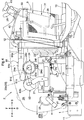
- External air that is to be supplied to the radiator 23 passes through the partition 3 on the rear side, and is taken in and brought to the radiator 23 as indicated by the arrow in Fig. 4 , cools the radiator 23, the engine 21 and the muffler 25, and is thereafter discharged from a portion of the front cover 20a on the front side.
- the air cleaner 24 is provided inside the hood 20 at a position above the engine 21 and forward of the radiator 23.
- An intake tube 61 that is used to take in external air is coupled to the air cleaner 24.
- a coupling tube 63 is coupled between the engine 21 and the air cleaner 24.
- the air cleaner 24 takes in external air via the intake tube 61, performs dust removal processing to remove dust such as cut grass and sand, and supplies the processed air to the engine 21 via the coupling tube 63.
- the air cleaner 24 has an elongated cylindrical shape and its longitudinal direction extends parallel with the right-left direction of the travel vehicle body 100.
- the air cleaner 24 includes a cylindrical side portion 24b that extends in the right-left direction, and a left side portion 24c and a right side portion 24d that are respectively located at the ends of the cylindrical side portion 24b in the right-left direction.
- An air intake port 24a from which external air is taken in is provided near the left side portion 24c of the air cleaner 24.
- the air intake port 24a is open rearward and obliquely downward at a position that is rearward of the engine 21 with respect to the machine body, and is forward of the radiator 23. External air passing through the partition 3 and the radiator 23 is taken in from the air intake port 24a to the inside of the air cleaner 24.
- a protrusion 24e is provided on the cylindrical side portion 24b of the air cleaner 24 so as to protrude forward and obliquely upward from the cylindrical side portion 24b. Also, an exhaust portion 24f is provided in the right side portion 24d of the air cleaner 24 such that the processed air subjected to dust removal processing performed by the air cleaner 24 may be discharged from the air cleaner 24.
- the intake tube 61 for taking in external air to the air cleaner 24, and the coupling tube 63 extending from the air cleaner 24 and coupled to the engine 21, are connected to the air cleaner 24.
- the intake tube 61 is connected to the protrusion 24e of the air cleaner 24. Therefore, the intake tube 61 extends along the protrusion 24e to a position that is forward of the air cleaner, and thereafter extends to a position that is rearward of the travel vehicle body 100.
- the intake tube 61 includes an intake open end portion 61a that is open at the rear end, an intake elongated portion 61b that extends from the intake open end portion 61a in the front-rear direction, an intake curved portion 61c that extends forward from the protrusion 24e and curves rearward toward the left, and an intake connection end portion 61d that is connected to the protrusion 24e.
- the intake open end portion 61a (the rear end portion of the intake tube 61) is located near the front side of the radiator 23 with a gap therefrom, for example. External air is taken in from the intake open end portion 61a, and is brought to the air cleaner 24 via the intake elongated portion 61b, the intake curved portion 61c and the intake connection end portion 61d.
- the coupling tube 63 is coupled to the exhaust portion 24f provided on the right side portion 24d of the air cleaner 24, and sends out processed air in the air cleaner 24 to the engine 21.
- the coupling tube 63 is coupled to the engine 21, and also extends in the right-left direction of the travel vehicle body 100, thereafter curves toward the exhaust portion 24f, and is coupled to the exhaust portion 24f.
- the coupling tube 63 includes a third pipe 63c that is coupled to an upper opening of the engine 21, a second pipe 63b that curves upward and to the right from the third pipe 63c and extends in the right-left direction, and a first pipe 63a that curves toward the exhaust portion 24f from the second pipe 63b and extends toward the air cleaner 24.
- the first pipe 63a extends forward and to the right from the exhaust portion 24f, thereafter curves forward and to the left, and is coupled to the second pipe 63b.
- the second pipe 63b extends in the right-left direction from the first pipe 63a, and is coupled to the third pipe 63c.
- the second pipe 63b extends downward from a left portion of the portion extending in the right-left direction such that the second pipe 63b can be coupled to the third pipe 63c.
- the third pipe 63c is coupled to the upper opening of the engine 21, and extends in the up-down direction.
- the third pipe 63c may curve toward the second pipe 63b so as to be coupled to the second pipe 63b.
- the coupling tube 63 between the air cleaner 24 and the engine 21 is coupled to the engine 21, while extending in the right-left direction of the travel vehicle body 100 and being coupled to the air cleaner 24.
- the coupling tube 63 includes the second pipe 63b that extends in the right-left direction of the travel vehicle body 100, and therefore processed air flowing through the coupling tube 63 also flows in the right-left direction and is brought to the engine 21. Therefore, at least some of the noise generated in an intake portion where the engine 21 is coupled to the coupling tube 63 and from which processed air is taken into the engine 21 does not travel rearward of the travel vehicle body 100, but instead travels in the right-left direction of the travel vehicle body 100 along with the processed air flowing in the right-left direction. As a result, it is possible to reduce noise generated in the intake portion and travelling toward the driver section 4 provided rearward of the air cleaner 24 and the engine 21.
- the coupling tube 63 between the air cleaner 24 and the engine 21 does not extend in the right-left direction, but instead extends rearward with respect to the travel vehicle body 100 and is coupled to the air cleaner 24, processed air that is brought from the air cleaner 24 to the engine 21 via the coupling tube 63 travels in the front-rear direction of the travel vehicle body 100. Therefore, noise generated in the intake portion where the engine 21 and the coupling tube 63 are coupled to each other travels rearward along with processed air flowing in the front-rear direction. For example, when the tractor travels forward, processed air flows rearward inside the hood 20, and noise travels further rearward toward the driver section 4. With the above-described configuration, however, it is possible to reduce noise travelling toward the driver section 4.
- the longitudinal direction of the air cleaner 24 extends parallel with the right-left direction of the travel vehicle body 100, and therefore, external air taken in by the air cleaner 24 mainly flows in the right-left direction compared to the front-rear direction. Therefore, it is possible to further reduce noise generated in the aforementioned intake portion and travelling toward the driver section 4 provided rearward of the air cleaner 24 and the engine 21.
- the exhaust portion 24f is provided in the right side portion 24d of the air cleaner 24. Therefore, while the coupling tube 63 coupled to the engine 21 extends in the right-left direction, the coupling tube 63 can be easily connected to the air cleaner 24.
- the intake tube 61 includes the intake curved portion 61c that does not extend rearward directly from the air cleaner 24, but instead first extends to a position that is forward of the air cleaner 24 and thereafter curves and extends rearward. Therefore, the flow of air taken in from the intake open end portion 61a of the intake tube 61 is weakened in the curved portion. As a result, it is possible to further reduce noise travelling toward the driver section 4.
- the air cleaner 24 is provided with the air intake port 24a and the intake tube 61, external air can be taken in from a plurality of positions. Therefore, it is possible to ensure that a sufficient amount of air is supplied to the engine 21. As a result, it is unlikely that incomplete combustion occurs in the engine 21 due to the lack of air.
- the protection frame 6 that is gate-shaped and is coupled to the rear end portion of the vehicle body frame 1 is provided in a rear portion of the driver seat 42.
- This gate-shaped protection frame 6 includes right and left supporting posts 6a and a coupling member 6b.
- the right and left supporting posts 6a are located rearward of the driver seat 42 on the right and left sides respectively.
- the right and left supporting posts 6a extend in the up-down direction, and extend toward the center in the right-left direction from the upper end portions so as to oppose each other.
- the upper end portions, which oppose each other, of the right and left supporting posts 6a are not continuous.
- the upper end portions, which oppose each other, of the right and left supporting posts 6a are coupled to each other by the coupling member 6b.
- a center-side end of the upper end portion of the left supporting post 6a and an end portion of the coupling member 6b are fixed by fastening members 6b1
- a center-side end of the upper end portion of the right supporting post 6a and an end portion of the coupling member 6b are fixed by fastening members 6b1.
- the protection frame 6 can be assembled by fitting the right and left supporting posts 6a to the travel vehicle body 100, and thereafter fixing them using the coupling members 6b. Therefore, the protection frame 6 can be easily assembled.
- the right and left supporting posts 6a curve at lower portions where are attached to the travel vehicle body 100, and also curve at upper portions. Therefore, only the right and left supporting posts 6a include curved portions. Also, the right and left supporting posts 6a have the same shape, and they can be manufactured more easily than when right and left members that are different from each other are manufactured.
- the prime mover section 2 may be of a hybrid type provided with the engine 21 and an electric motor.
- An HST linkage mechanism 120 shown in Figs. 7 and 8 is a mechanism for transmitting an operation performed on the HST operation pedal 51 to the HST 50.
- the HST linkage stay 90 swings about a shaft 95 in response to the operation, the inclined plate (not shown) of the HST 50 is controlled by the swing, and an output from the HST 50 is controlled.
- the HST linkage stay 90 is made of a single plate, and has a polygonal shape with a plurality of protrusions as a result of protrusions and recesses being formed along the plate surface.
- the shaft 95 is formed on one protrusion, and through holes 91, 92, 93, and 94 are formed in protrusions at other positions.
- the shaft 95 of the HST linkage stay 90 is coupled to the vehicle body frame 1 ( Fig. 1 , etc.) so as to be swingable.
- An end portion of a rod 83 that couples the HST 50 and the HST linkage stay 90 to each other is pivotably supported by the through hole 92.
- the through hole 91 is used to couple another member (not shown) to the HST linkage stay 90.
- the other through holes 93 and 94 are used in the following manner.
- a cylinder 81 for alleviating a rapid operation transmitted to the HST 50 is coupled to the HST linkage stay 90 via an interposed member 101.
- One end portion of the cylinder 81 is fixed to the vehicle body frame 1, and the other end portion is coupled to a fastening portion 101c of the interposed member 101.
- the through hole 93 of the HST linkage stay 90 is elongated, and a lock member 101b of the interposed member 101 is movable along the elongated through hole 93.
- a fastening portion 101a of the interposed member 101 is coupled to the through hole 94 of the HST linkage stay 90.
- the cylinder 81 expands and contracts, and the lock member 101b of the interposed member 101 moves along the elongated through hole 93.
- a rapid operation transmitted to the HST 50 can be alleviated.
- the HST linkage stay 90 of the HST linkage mechanism 120 is made of a single plate, and the configuration can be simplified.
- the second pipe 63b of the coupling tube 63 is slightly larger than the first pipe 63a and the third pipe 63c.
- the second pipe 63b is not limited to such a configuration, size or diameter, and may be formed similarly to the first pipe 63a and the second pipe 63b.
- front refers to the direction in which a riding work vehicle M travels forward during working travel (see arrows F in Figs. 9 and 10 )
- rear refers to the direction in which the tractor travels rearward (see arrows B in Figs. 9 and 10 )
- right refers to the direction corresponding to the right side relative to the forward orientation of the tractor in the front-rear direction (see an arrow R in Fig. 10 )
- left refers to the direction corresponding to the left side (see an arrow L in Fig. 10 ).
- the tractor in the present embodiment which is an example of a riding work vehicle, is configured as described below.
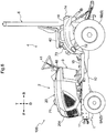
- Fig. 9 is a left side view of the riding work vehicle M
- Fig. 10 is a plan view of the riding work vehicle M
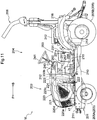
- Fig. 11 shows a state in which a partition provided in the riding work vehicle is removed.
- the riding work vehicle M illustrated in the present embodiment is provided with a prime mover section 202 located in a front portion of space inside a hood 220 provided in a front portion of the machine body, and a driver section 204 provided with a dashboard 240 provided rearward of the hood 220 and a driver seat 242 located apart from the dashboard 240 rearward.
- the prime mover section 202 is supported on the front side of a vehicle body frame 201 that forms a framework of a vehicle body.
- the driver section 204 is located on the rear side of the vehicle body frame 201.
- a protection frame 206 is coupled to a rear end portion of the vehicle body frame 201.
- the riding work vehicle M is provided with wheels 205 that include front wheels 205A and rear wheels 205B.
- the vehicle body frame 201 includes a pair of right and left side members 210 that are made of steel plates and extend in the front-rear direction, and a front member 211 that is made of a steel plate and spans between the front ends of the right and left side members 210.
- a center pillar 212 that spans between the right and left side members 210 is provided at a substantially central position in the front-rear direction of the right and left side members 210.
- a transmission 213 that transmits power from an engine 221 provided in the prime mover section 202 to the wheels 205 and so on while performing speed conversion is attached to a position near rear end portions of the right and left side members 210.
- a driver seat 242 is located above the transmission 213, a driver section step 215 on which the driver can ride is provided within the gap between the driver seat 242 and the prime mover section 202 in the front-rear direction, and rear wheel fenders 216 are provided on the right and left sides of the driver seat 242.
- a dashboard 240 is provided at a position located rearward of the hood 220 of the prime mover section 202.
- the dashboard 240 is provided with a steering wheel 241 for steering the front wheels, and indicators that indicate the engine speed and so on, and functions as a member that constitutes a part of the driver section 204.
- a partition 203 described below is provided between a lower portion of the above-described dashboard 240 and the driver section step 215. Therefore, while being used as a constituent element of the driver section 204 equipped with indicators or the like, the dashboard 240 also functions as an upper lid of the partition 203, and as a member of the prime mover section 202 constituting a part of an engine room 202A of the prime mover section 202 together with the partition 203.
- the prime mover section 202 space located forward of the center pillar 212 fixed so as to span between the right and left side members 210 is an engine room 202A that is covered by the hood 220.
- the dashboard 240 that constitutes a part of the driver section 204 is provided above the partition 203.
- the space covered by the hood 220 and the space inside the partition 203 constitute the engine room 202A that is the internal space of the prime mover section 202.
- the hood 220 is of an integrated type in which a front cover 220a that covers a front end portion of the prime mover section 202 and allows air to pass, right and left side covers 220b that cover lateral side portions of the prime mover section 202, an upper cover 220c that covers an upper portion of the prime mover section 202, head light units 220d, and so on are coupled to each other and integrated into one piece.
- This hood 220 is configured to be able to swing to open and close in the up-down direction about a pivot axis xl located at a front end portion of the vehicle body frame 201 and extending in the right-left direction.
- the hood 220 is configured to be able to swing in a up-down direction between a closed position where the hood 20 covers the prime mover section 202 and an open position where the hood 220 does not cover the prime mover section 202, and is configured to be of a rear-open type, i.e. a rear portion of the space inside the hood 220 is wide open when the hood 220 is in the open position.
- a radiator 223, an air cleaner 224, and so on provided in a rear portion of the prime mover section 202.
- the radiator 223 is provided in a rear end portion of the engine room 202A, and a cooling fan 222 for taking in external air and bringing the external air into contact with the radiator 223 is provided in the engine room 202A at a position that is forward of the radiator 223.
- External air that is to be supplied to the radiator 223 passes through the partition 203 on the rear side, and is taken in and brought to the radiator 223, cools the radiator 223, the engine 221, a muffler, and so on, and is thereafter discharged from a portion of the front cover 220a on the front side.
- the partition 203 according to the present embodiment is formed using an external wall plate 231 that is a metal plate in which a plurality of holes 231a are formed (such as a punching metal), and thus air is allowed to pass through the partition 203.
- An intake port (not shown) of the air cleaner 224 is provided inside the hood 220 at a position that is rearward of the engine 221 with respect to the machine body, and is forward of the radiator 223, so as to face toward the rear side. External air passing through the partition 203 and the radiator 223 is taken in from the air intake port to the inside of the air cleaner 224.
- the partition 203 is provided below the dashboard 240 at the boundary between the internal space of the hood 220 and the driver section 204.
- the partition 203 is provided above the driver section step 215.
- An intermediate portion of the partition 203 in the right-left direction bulges rearward, and the partition 203 is substantially gate-shaped in plan view.
- An internal space s1 on the inner peripheral side of the partition 203 that is gate-shaped in plan view is used as a space that accommodates a battery 226 and a communication device 260 described below.
- the partition 203 is configured to pass radio waves therethrough, and is installed so as to be detachable from the hood 220.
- the internal space s1 of the hood 220 covered by the partition 203 below the dashboard 240 is provided with a work vehicle-side connector 250 to which a communication device 260 that realizes a communication function using radio waves can be connected.
- the partition 203 is formed using a metal plate (the external wall plate 231) in which the plurality of holes 231a are formed, and therefore the partition 203 allows radio waves to pass therethrough.
- the partition 203 is located apart from the driver seat 242 on which an occupant H can sit, and therefore radio waves are not blocked by the body of the occupant H.
- the communication device 260 when the communication device 260 is provided in the internal space s1 of the hood 220 covered by the partition 203, the communication device 260 can transmit and receive radio waves to and from an external device due to the presence of the holes 231a in the external wall plate 231 that constitutes the partition 203.
- the partition 203 is formed using the external wall plate 231 that is made of metal, and therefore the partition 203 achieves sufficient strength.
- the external wall plate 231 that constitutes the partition 203 is installed so as to be detachable from the hood 220, and a user of the riding work vehicle M can easily access the work vehicle-side connector 250 provided in the internal space sl. That is to say, a user of the riding work vehicle M can freely install and uninstall the communication device 260 in the riding work vehicle M.
- the external wall plate 231 that constitutes the partition 203 by attaching the external wall plate 231 that constitutes the partition 203 to the riding work vehicle M, it is possible to protect the contents of the internal space s1 with the external wall plate 231. Therefore, it is possible to prevent a foreign object or the like, such as rainwater and sand, from attaching to the communication device 260 installed in the internal space s1.
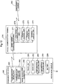
- Fig. 12 is a block diagram showing an example of a specific configuration of a work vehicle information management system.
- the work vehicle information management system is configured to perform information communication between the riding work vehicle M and a management center 280 in a remote location.
- the above-described work vehicle-side connector 250 is installed in the riding work vehicle M in the present embodiment. That is to say, a user who wishes to install an information communication function to the riding work vehicle M may connect the communication device 260 to the work vehicle-side connector 250, and a user who does not wish to install an information communication function does not have to install the communication device 260 to the work vehicle-side connector 250.
- the riding work vehicle M includes the work vehicle-side connector 250, a travel unit 251, a work unit 252, an information collecting unit 253, an information storage unit 254, and a battery 226.
- the travel unit 251 is a unit related to the travel of the riding work vehicle M, and includes the engine 221, the transmission 213, the wheels 205, a fuel tank (not shown) that supplies fuel to the engine 221, and so on.
- the work unit 252 is, for example, a mower unit that has a mowing blade when the riding work vehicle M is used as a mowing machine.
- the information collecting unit 253 is a unit that collects information indicating the state of each unit included in the riding work vehicle M.
- the information collecting unit 253 collects pieces of information regarding the temperature of the cooling water of the engine 221, the remaining amount of fuel in a fuel tank (not shown), the remaining capacity of the battery 226, accumulated operation time and so on, from the units included in the riding work vehicle M. Pieces of information collected by the information collecting unit 253 are stored in the information storage unit 254.
- the communication device 260 includes a communication device body 261 and a communication device-side connector 262.
- a device that complies with short-range wireless communication standards such as Bluetooth (registered trademark) and Wi-Fi (registered trademark) may be used as the communication device body 261.
- the communication device-side connector 262 of the communication device 260 is to be connected to the work vehicle-side connector 250 of the riding work vehicle M.
- a mobile communication terminal 270 includes a short-range communication unit 271, a long-range communication unit 272, a terminal control unit 273, a terminal storage unit 274, and a terminal display unit 275 such as a display.
- the mobile communication terminal 270 is a mobile terminal that is used by the occupant H of the riding work vehicle M and is brought in the riding work vehicle M, for example, such as a smartphone, a tablet terminal, or a laptop computer.
- the short-range communication unit 271 of the mobile communication terminal 270 realizes the function of performing communication with the communication device 260 installed in the riding work vehicle M, and short-range wireless communication standards such as Bluetooth (registered trademark) and Wi-Fi (registered trademark) may be used.
- the long-range communication unit 272 of the mobile communication terminal 270 realizes the function of communicating with the external management center 280 via a communication network such as a mobile telephone network or the Internet.
- the terminal control unit 273 executes a communication program that has been installed in the terminal storage unit 274 in advance, and thus information communication between the mobile communication terminal 270 and the communication device 260 installed in the riding work vehicle M (the function of the short-range communication unit 271) and information communication between the mobile communication terminal 270 and the management center 280 (the function of the long-range communication unit 272) are realized.
- a communication path is established between the riding work vehicle M and the management center 280 via the communication device 260 and the mobile communication terminal 270.
- Pieces of information collected by the riding work vehicle M at predetermined timing, such as once per day, are transmitted to an external device via the communication device 260 together with identification information that is unique to the riding work vehicle M, for example.
- Pieces of emergency information such as information indicating that the temperature of the cooling water for the engine 221 has reached the upper temperature limit and information indicating that the cumulative operation time has reached the upper limit period, may be immediately transmitted to an external device via the communication device 260 when such information is generated.
- the management center 280 can continuously acquire information from the riding work vehicle M specified by the identification information, and can immediately acquire emergency information.
- the terminal control unit 273 of the mobile communication terminal 270 may display information received from the riding work vehicle M via the communication device 260, on the terminal display unit 275. As a result, the occupant H of the riding work vehicle M can access pieces of information collected by the riding work vehicle M.
Landscapes
- Engineering & Computer Science (AREA)
- Chemical & Material Sciences (AREA)
- Combustion & Propulsion (AREA)
- Mechanical Engineering (AREA)
- General Engineering & Computer Science (AREA)
- Cooling, Air Intake And Gas Exhaust, And Fuel Tank Arrangements In Propulsion Units (AREA)
Abstract
Description
- The present invention relates to work vehicles, and specifically relates to riding work vehicles such as tractors.
-
JP 2015-163512A EP 3 109 085 A1 - The turbocharger is a pipe extending in the front-rear direction of the machine body, and is attached to an upper end portion of the engine. Therefore, clean air from the air cleaner is supplied to the engine via a pipe that is bent toward the upper end portion of the engine at the rear end in the front-rear direction of the machine body. Here, the engine takes in air from a portion where the engine is connected to the pipe, and noise generated in the portion where the engine takes in air reaches the driver section located rearward of the engine.
- An object of the invention is to provide a work vehicle that can reduce noise that reaches the driver section.
-
JP 2017-197162 A US 2017/0129543 A1 corresponding thereto) discloses a riding work vehicle provided with a prime mover section located in a front portion of space inside a hood provided in a front portion of the machine body, and a driver section provided with a dashboard provided rearward of the hood and a driver seat located apart from the dashboard rearward. - When maintenance work is to be performed on such a riding work vehicle, if pieces of information such as the operation state of the prime mover section such as an engine, the remaining amount of fuel, and the remaining capacity of a battery are stored in a memory or the like provided in the riding work vehicle, a maintenance worker may be able to appropriately diagnose the state of the riding work vehicle, a cause of a failure, and so on by reading out and analyzing such pieces of information.
- If pieces of information collected by the riding work vehicle can be transmitted to a management center or the like in a remote location via a communication network, a maintenance worker can grasp the state of the riding work vehicle at the management center without checking the state of the riding work vehicle on the work site. To achieve such transmission, it is necessary to install a communication device that realizes a communication function using, for example, radio waves, in the riding work vehicle in advance.
- However, some users does not wish to install such a communication device.
- The present invention aims to provide a riding work vehicle with which a user can easily change whether or not to install a communication device in the riding work vehicle.
-
- [1] A work vehicle as below is proposed in correspondence with First Related Art:
A work vehicle comprising:- a travel vehicle body;
- a prime mover section that is provided in a front portion of the travel vehicle body;
- a hood that covers the prime mover section;
- a driver section that is provided rearward of the prime mover section, the driver section having a driver seat;
- an engine that is provided inside the hood;
- an air cleaner that is provided inside the hood above the engine for processing external air that is to be supplied to the engine;
- an intake tube that is coupled to the air cleaner for taking air into the air cleaner; and
- a coupling tube that is coupled between the engine and the air cleaner for supplying, to the engine, processed air that is provided by passing external air through the air cleaner, the coupling tube being coupled to the engine and extending in a right-left direction of the travel vehicle body and being coupled to the air cleaner.
- With this configuration, the coupling tube between the air cleaner and the engine is coupled to the engine, while extending in the right-left direction of the travel vehicle body and being coupled to the air cleaner. The coupling tube includes a section that extends in the right-left direction of the travel vehicle body, and therefore processed air flowing through the coupling tube also flows in the right-left direction and is brought to the engine. Therefore, at least some of the noise generated in an intake portion where the engine is coupled to the coupling tube and from which processed air is taken into the engine does not travel rearward of the travel vehicle body, but instead travels in the right-left direction of the travel vehicle body along with the processed air flowing in the right-left direction. As a result, it is possible to reduce noise generated in the intake portion and travelling toward the driver section provided rearward of the air cleaner and the engine.
- In one preferred embodiment, a longitudinal direction of the air cleaner is parallel with the right-left direction of the travel vehicle body.
- With the above-described configuration, the longitudinal direction of the air cleaner is parallel with the right-left direction of the travel vehicle body, and therefore a larger amount of external air taken in by the air cleaner flows in the right-left direction than in the front-rear direction. Therefore, it is possible to further reduce noise generated in the intake portion and travelling toward the driver section provided rearward of the air cleaner and the engine.
- In one preferred embodiment, an exhaust portion is provided on one lateral side of the air cleaner for discharging the processed air, and the coupling tube extends from the engine in the right-left direction of the travel vehicle body, thereafter curves toward the exhaust portion, and is coupled to the exhaust portion.
- With the above-described configuration, in addition to the fact that the longitudinal direction of the air cleaner is parallel with the right-left direction of the travel vehicle body, the exhaust portion is provided on a side of the air cleaner. Therefore, while a configuration in which the coupling tube coupled to the engine extends in the right-left direction is employed, the coupling tube can be easily connected to the air cleaner.
- In one preferred embodiment, the intake tube extends from a portion where the intake tube is coupled to the air cleaner, thereafter extends to a position forward of the air cleaner, and curves and extends to a position that is rearward with respect to the travel vehicle body.
- With the above-described configuration, the intake tube does not extend rearward directly from the air cleaner, but instead first extends to a position that is forward of the air cleaner, and thereafter curves and extends rearward. Therefore, the flow in the front-rear direction of air taken in from an open end of the intake tube is weakened in the curved portion. As a result, it is possible to further reduce noise travelling toward the driver section.
- In one preferred embodiment, the work vehicle further includes a radiator that is provided rearward of the engine and cools cooling water for cooling the engine; and a cooling fan that is provided immediately forward of the radiator, and an end portion, from which external air is taken in, of the intake tube is located rearward of the radiator.
- With the above-described configuration, the rear end portion of the intake tube is located rearward of the radiator. Therefore, it is possible to realize a configuration in which cooling air that has not been supplied to the radiator is taken into the air cleaner via the intake tube. As a result, it is unlikely that incomplete combustion occurs in the engine due to the lack of air.
A work vehicle as below is proposed in correspondence with Second Related Art:
A riding work vehicle comprising: - a travel vehicle body;
- a hood that is provided in a front portion of the travel vehicle body;
- a prime mover section that is provided in a front portion of an internal space of the hood;
- a driver section that is provided rearward of the prime mover section, the driver section having a dashboard that is provided at a rear end portion of the hood, and a driver seat that is located apart from the dashboard rearward;
- a connector that is provided in a rear portion of the internal space below the dashboard, the connector being connectable to a communication device that realizes a communication function using radio waves; and
- a partition that is provided below the dashboard at a boundary between the internal space and the driver section, the partition being configured to allow radio waves to pass therethrough, and to be detachable from the hood.
- With this configuration, the partition allows radio waves to pass therethrough. Therefore, when a communication device is connected to a connector that is provided in the internal space of the hood covered by the partition, the communication device can transmit and receive radio waves to and from an external device through the partition.
- In addition, the partition is installed so as to be detachable from the hood, the user of the riding work vehicle can easily access the space in which the connector is provided. That is to say, the user of the riding work vehicle can freely install and uninstall the communication device in the riding work vehicle. Furthermore, by attaching the partition to the riding work vehicle, it is possible to protect the internal space in which the communication device is installed. Therefore, it is possible to prevent a foreign object or the like, such as rainwater and sand, from attaching to the communication device installed in the internal space.
- Therefore, it is possible to provide a riding work vehicle with which a user can easily change whether or not to install a communication device in the riding work vehicle.
- In one preferred embodiment, the partition is formed of a metal plate in which a plurality of holes are formed.
- With the above-described configuration, the communication device provided in the internal space of the hood covered by the partition can transmit and receive radio waves to and from an external device due to the presence of the holes formed in the metal plate that constitutes the partition. In addition, the partition is formed using the metal plate, and therefore the partition achieves sufficient strength.
Other features and advantages produced thereby will become apparent by reading the following descriptions. -
-
Fig. 1 is a left side view of a tractor according to a first embodiment (the same applies up toFig. 8 ); -
Fig. 2 is a plan view of the tractor; -
Fig. 3 is a rear view of the tractor; -
Fig. 4 is a left side view showing space in an engine room of a prime mover section; -
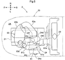
Fig. 5 is a plan view showing configurations of an air cleaner, a coupling tube and an intake tube; -
Fig. 6 is a left side view showing an arrangement of light units according to another embodiment; -
Fig. 7 is a side view showing an example of a configuration of an HST linkage mechanism; -
Fig. 8 is a perspective view of an HST linkage stay shown inFig. 7 ; -
Fig. 9 is a left side view of a riding work vehicle (a tractor) according to a second embodiment (the same applies up toFig. 12 ); -
Fig. 10 is a plan view of the riding work vehicle; -
Fig. 11 shows a state in which a partition provided in the riding work vehicle is removed; and -
Fig. 12 is a block diagram showing an example of a specific configuration of a work vehicle information management system. - In the first embodiment, a tractor is an example of the work vehicle.
- In the following description, unless explicitly described otherwise, "front" refers to the direction in which the tractor travels forward during working travel (see arrows F in
Figs. 1 and2 ), "rear" refers to the direction in which the tractor travels rearward (see arrows B inFigs. 1 and2 ), "right" refers to the direction corresponding to the right side relative to the forward orientation of the tractor in the front-rear direction (see an arrow R inFig. 2 ), and "left" refers to the direction corresponding to the left side (see an arrow L inFig. 2 ). "Up" refers to the direction corresponding to the upper side (see an arrow T inFig. 1 ), and "down" refers to the direction corresponding to the lower side (see an arrow D inFig. 1 ). - The tractor in the present embodiment, which is an example of a work vehicle, is configured as described below.
- As shown in
Figs. 1 and2 , the tractor is constituted by atravel vehicle body 100 that includes avehicle body frame 1, which forms a framework of a vehicle body, aprime mover section 2, which is supported on the front side of thevehicle body frame 1, a riding-type driver section 4, which is located on the rear side of thevehicle body frame 1, right and left travelingapparatuses 5, aprotection frame 6, which is coupled to a rear end portion of thevehicle body frame 1, etc. - The right and left
travel apparatuses 5 are of a four-wheel drive type, including right and leftfront wheels 5A, which are steerable and are driven by power from theprime mover section 2, and right and leftrear wheels 5B, which are driven by power from theprime mover section 2. - As shown in
Figs. 1 to 4 , thevehicle body frame 1 includes a pair of right and leftside members 10 that are made of steel plates and extend in the front-rear direction, and afront member 11 that is made of a steel plate and spans between the front ends of the right and leftside members 10. - In addition, a
center pillar 12 spans between the right and leftside members 10 at a substantially central position in the front-rear direction of the right and leftside members 10. Also, atransmission 13 is attached to a position near rear end portions of the right and leftside members 10 for transmitting power from anengine 21 provided in theprime mover section 2 to the right and left travelingapparatuses 5 and so on, while performing speed conversion. - An HST (Hydrostatic Transmission) 50 is provided in the
transmission 13 as an example of a continuously variable transmission mechanism, correspondingly to the right and leftfront wheels 5A and the right and leftrear wheels 5B in the right and lefttravel apparatuses 5. Adriver section step 15 described below is provided with anHST operation pedal 51. Upon theHST operation pedal 51 being operated, the operation performed on theHST operation pedal 51 is transmitted to theHST 50 via an HST linkage mechanism (not shown), and theHST 50 is subjected to continuously variable speed conversion. - In the
driver section 4 provided rearward of theprime mover section 2, adriver seat 42 is located above thetransmission 13; thedriver section step 15 on which the driver can ride is provided within the gap between thedriver seat 42 and theprime mover section 2 in the front-rear direction; andrear wheel fenders 16 are provided on the right and left sides of thedriver seat 42. - A
dashboard 40 is provided at a position located rearward of thehood 20 of theprime mover section 2. Thedashboard 40 is provided with asteering wheel 41 for steering the front wheels, and indicators that indicate the engine speed and so on, and functions as a member that constitutes a part of thedriver section 4. - As shown in
Fig. 4 , a throttle lever 27 that is used to operate a throttle of the engine is provided at a position on the lateral side of the body of theengine 21. The throttle lever 27 is supported so as to be pivotable in a horizontal direction about a vertical axis yl as shown inFig. 4 , and anaccelerator wire 28 is coupled to the leading end of the throttle lever 27. - Therefore, the
accelerator wire 28 is pushed and pulled in response to an operation performed using anaccelerator operation tool 29 that is provided in thedriver section 4, and accordingly the rotation angle of the throttle lever 27 is changed and the speed of therotation engine 21 is adjusted. - A
partition 3 described below is provided between thedriver section step 15 and a lower portion of the above-describeddashboard 40. - Therefore, while being used as a constituent element of the
driver section 4 equipped with indicators or the like, thedashboard 40 also functions as an upper lid of thepartition 3, and as a member of theprime mover section 2 constituting a part of anengine room 2A of theprime mover section 2 together with thepartition 3. - The
partition 3 is a combination of amain frame 30 that is grid-shaped, and anexternal wall plate 31 having a large number of ventilation holes and provided on the rear surface of themain frame 30. - The
partition 3 is provided at a position below thedashboard 40 and above thedriver section step 15. An intermediate portion of thepartition 3 in the right-left direction bulges rearward, and thepartition 3 is substantially gate-shaped in plan view. Abattery 26 is housed in space on the inner peripheral side of thepartition 3 that is gate-shaped in plan view. - The
prime mover section 2 has a configuration described below. - As shown in
Figs. 1 to 4 , in theprime mover section 2, space located forward of thecenter pillar 12 fixed so as to span between the right and leftside members 10 defines anengine room 2A that is covered by thehood 20. In a space that is rearward of thecenter pillar 12, thedashboard 40 that constitutes a part of thedriver section 4 is provided above thepartition 3. Thus, the space covered by thehood 20 and the space inside thepartition 3 constitute theengine room 2A that is the internal space of theprime mover section 2. - The
engine 21, which is a water-cooled type gasoline engine supported on a front portion of thevehicle body frame 1 so as to be vibration-proof, is provided in theengine room 2A. Furthermore, a coolingfan 22 that is located rearward of theengine 21, aradiator 23 that is located rearward of the coolingfan 22, anair cleaner 24 that is located above theengine 21, amuffler 25 that is located forward of theengine 21, and so on are provided in theengine room 2A. - The
hood 20 is of an integrated type in which afront cover 20a that covers a front end portion of theprime mover section 2 and allows air to pass, right and left side covers 20b that cover lateral side portions of theprime mover section 2, anupper cover 20c that covers an upper portion of theprime mover section 2,head light units 20d, and so on are coupled to each other and integrated into one piece. Thishood 20 is configured to be able to swing to open and close in the up-down direction about a pivot axis x1 located at a front end portion of thevehicle body frame 1 and extending in the right-left direction. - Thus, the
hood 20 is configured to be able to swing in a up-down direction between a closed position where thehood 20 covers theprime mover section 2 and an open position where thehood 20 does not cover theprime mover section 2, and is configured to be of a rear-open type, i.e. a rear portion of the space inside thehood 20 is wide open when thehood 20 is in the open position. As a result, it is easy to perform maintenance work on theradiator 23, theair cleaner 24 and so on provided in a rear portion of theprime mover section 2. - The
radiator 23 is provided in a rear end portion of theengine room 2A, and the coolingfan 22 for taking in external air and bringing the external air into contact with theradiator 23 is provided in theengine room 2A at a position that is forward of theradiator 23. External air that is to be supplied to theradiator 23 passes through thepartition 3 on the rear side, and is taken in and brought to theradiator 23 as indicated by the arrow inFig. 4 , cools theradiator 23, theengine 21 and themuffler 25, and is thereafter discharged from a portion of thefront cover 20a on the front side. - The
air cleaner 24 is provided inside thehood 20 at a position above theengine 21 and forward of theradiator 23. Anintake tube 61 that is used to take in external air is coupled to theair cleaner 24. Also, acoupling tube 63 is coupled between theengine 21 and theair cleaner 24. Theair cleaner 24 takes in external air via theintake tube 61, performs dust removal processing to remove dust such as cut grass and sand, and supplies the processed air to theengine 21 via thecoupling tube 63. - The following further describes the configuration of the
air cleaner 24 with reference toFigs. 4 and5 . - The
air cleaner 24 has an elongated cylindrical shape and its longitudinal direction extends parallel with the right-left direction of thetravel vehicle body 100. Theair cleaner 24 includes acylindrical side portion 24b that extends in the right-left direction, and aleft side portion 24c and aright side portion 24d that are respectively located at the ends of thecylindrical side portion 24b in the right-left direction. Anair intake port 24a from which external air is taken in is provided near theleft side portion 24c of theair cleaner 24. Theair intake port 24a is open rearward and obliquely downward at a position that is rearward of theengine 21 with respect to the machine body, and is forward of theradiator 23. External air passing through thepartition 3 and theradiator 23 is taken in from theair intake port 24a to the inside of theair cleaner 24. - A
protrusion 24e is provided on thecylindrical side portion 24b of theair cleaner 24 so as to protrude forward and obliquely upward from thecylindrical side portion 24b. Also, anexhaust portion 24f is provided in theright side portion 24d of theair cleaner 24 such that the processed air subjected to dust removal processing performed by theair cleaner 24 may be discharged from theair cleaner 24. - The
intake tube 61 for taking in external air to theair cleaner 24, and thecoupling tube 63 extending from theair cleaner 24 and coupled to theengine 21, are connected to theair cleaner 24. - The
intake tube 61 is connected to theprotrusion 24e of theair cleaner 24. Therefore, theintake tube 61 extends along theprotrusion 24e to a position that is forward of the air cleaner, and thereafter extends to a position that is rearward of thetravel vehicle body 100. As a result, theintake tube 61 includes an intakeopen end portion 61a that is open at the rear end, an intakeelongated portion 61b that extends from the intakeopen end portion 61a in the front-rear direction, an intakecurved portion 61c that extends forward from theprotrusion 24e and curves rearward toward the left, and an intakeconnection end portion 61d that is connected to theprotrusion 24e. - The intake
open end portion 61a (the rear end portion of the intake tube 61) is located near the front side of theradiator 23 with a gap therefrom, for example. External air is taken in from the intakeopen end portion 61a, and is brought to theair cleaner 24 via the intake elongatedportion 61b, the intake curvedportion 61c and the intakeconnection end portion 61d. - The
coupling tube 63 is coupled to theexhaust portion 24f provided on theright side portion 24d of theair cleaner 24, and sends out processed air in theair cleaner 24 to theengine 21. Specifically, thecoupling tube 63 is coupled to theengine 21, and also extends in the right-left direction of thetravel vehicle body 100, thereafter curves toward theexhaust portion 24f, and is coupled to theexhaust portion 24f. Thecoupling tube 63 includes athird pipe 63c that is coupled to an upper opening of theengine 21, asecond pipe 63b that curves upward and to the right from thethird pipe 63c and extends in the right-left direction, and afirst pipe 63a that curves toward theexhaust portion 24f from thesecond pipe 63b and extends toward theair cleaner 24. - The
first pipe 63a extends forward and to the right from theexhaust portion 24f, thereafter curves forward and to the left, and is coupled to thesecond pipe 63b. Thesecond pipe 63b extends in the right-left direction from thefirst pipe 63a, and is coupled to thethird pipe 63c. Thesecond pipe 63b extends downward from a left portion of the portion extending in the right-left direction such that thesecond pipe 63b can be coupled to thethird pipe 63c. Thethird pipe 63c is coupled to the upper opening of theengine 21, and extends in the up-down direction. Thethird pipe 63c may curve toward thesecond pipe 63b so as to be coupled to thesecond pipe 63b. - With the above-described configuration, the
coupling tube 63 between theair cleaner 24 and theengine 21 is coupled to theengine 21, while extending in the right-left direction of thetravel vehicle body 100 and being coupled to theair cleaner 24. Thecoupling tube 63 includes thesecond pipe 63b that extends in the right-left direction of thetravel vehicle body 100, and therefore processed air flowing through thecoupling tube 63 also flows in the right-left direction and is brought to theengine 21. Therefore, at least some of the noise generated in an intake portion where theengine 21 is coupled to thecoupling tube 63 and from which processed air is taken into theengine 21 does not travel rearward of thetravel vehicle body 100, but instead travels in the right-left direction of thetravel vehicle body 100 along with the processed air flowing in the right-left direction. As a result, it is possible to reduce noise generated in the intake portion and travelling toward thedriver section 4 provided rearward of theair cleaner 24 and theengine 21. - In this connection, it is known that noise generated in the intake portion is dominant over noise generated in the
coupling tube 63, theair cleaner 24 and so on. Therefore, reducing noise generated in the intake portion is effective for reducing noise travelling toward thedriver section 4. - Note that if the
coupling tube 63 between theair cleaner 24 and theengine 21 does not extend in the right-left direction, but instead extends rearward with respect to thetravel vehicle body 100 and is coupled to theair cleaner 24, processed air that is brought from theair cleaner 24 to theengine 21 via thecoupling tube 63 travels in the front-rear direction of thetravel vehicle body 100. Therefore, noise generated in the intake portion where theengine 21 and thecoupling tube 63 are coupled to each other travels rearward along with processed air flowing in the front-rear direction. For example, when the tractor travels forward, processed air flows rearward inside thehood 20, and noise travels further rearward toward thedriver section 4. With the above-described configuration, however, it is possible to reduce noise travelling toward thedriver section 4. - Also, the longitudinal direction of the
air cleaner 24 extends parallel with the right-left direction of thetravel vehicle body 100, and therefore, external air taken in by theair cleaner 24 mainly flows in the right-left direction compared to the front-rear direction. Therefore, it is possible to further reduce noise generated in the aforementioned intake portion and travelling toward thedriver section 4 provided rearward of theair cleaner 24 and theengine 21. - In addition to the fact that the longitudinal direction of the
air cleaner 24 extends parallel with the right-left direction of thetravel vehicle body 100, theexhaust portion 24f is provided in theright side portion 24d of theair cleaner 24. Therefore, while thecoupling tube 63 coupled to theengine 21 extends in the right-left direction, thecoupling tube 63 can be easily connected to theair cleaner 24. - Also, the
intake tube 61 includes the intake curvedportion 61c that does not extend rearward directly from theair cleaner 24, but instead first extends to a position that is forward of theair cleaner 24 and thereafter curves and extends rearward. Therefore, the flow of air taken in from the intakeopen end portion 61a of theintake tube 61 is weakened in the curved portion. As a result, it is possible to further reduce noise travelling toward thedriver section 4. - As the
air cleaner 24 is provided with theair intake port 24a and theintake tube 61, external air can be taken in from a plurality of positions. Therefore, it is possible to ensure that a sufficient amount of air is supplied to theengine 21. As a result, it is unlikely that incomplete combustion occurs in theengine 21 due to the lack of air. - The following further describes the configuration of the
protection frame 6 with reference toFigs. 1 to 3 . - As shown in
Figs. 1 to 3 , theprotection frame 6 that is gate-shaped and is coupled to the rear end portion of thevehicle body frame 1 is provided in a rear portion of thedriver seat 42. - This gate-shaped
protection frame 6 includes right and left supportingposts 6a and acoupling member 6b. The right and left supportingposts 6a are located rearward of thedriver seat 42 on the right and left sides respectively. The right and left supportingposts 6a extend in the up-down direction, and extend toward the center in the right-left direction from the upper end portions so as to oppose each other. The upper end portions, which oppose each other, of the right and left supportingposts 6a are not continuous. The upper end portions, which oppose each other, of the right and left supportingposts 6a are coupled to each other by thecoupling member 6b. That is to say, a center-side end of the upper end portion of theleft supporting post 6a and an end portion of thecoupling member 6b are fixed by fastening members 6b1, and a center-side end of the upper end portion of theright supporting post 6a and an end portion of thecoupling member 6b are fixed by fastening members 6b1. - With the above-described configuration of the
protection frame 6, theprotection frame 6 can be assembled by fitting the right and left supportingposts 6a to thetravel vehicle body 100, and thereafter fixing them using thecoupling members 6b. Therefore, theprotection frame 6 can be easily assembled. The right and left supportingposts 6a curve at lower portions where are attached to thetravel vehicle body 100, and also curve at upper portions. Therefore, only the right and left supportingposts 6a include curved portions. Also, the right and left supportingposts 6a have the same shape, and they can be manufactured more easily than when right and left members that are different from each other are manufactured. -
- (1) In the above-described embodiment, the
air cleaner 24 is positioned such that the longitudinal direction thereof coincides with the right-left direction. However, it suffices if a section of thecoupling pipe 63 extending from theengine 21 to theair cleaner 24 at least includes thesecond pipe 63b that extends in the right-left direction. Therefore, for example, theair cleaner 24 may be positioned such that the longitudinal direction thereof coincides with the front-rear direction. It suffices if thecoupling tube 63 extends in the right-left direction, and is coupled to a side portion of theair cleaner 24 in the longitudinal direction, i.e. thecylindrical side portion 24b shown inFig. 5 . Alternatively, thecoupling tube 63 may extend in the right-left direction, and may be coupled to a front end portion of theair cleaner 24 in the longitudinal direction (theright side portion 24d or theleft side portion 24c shown inFig. 5 ).
In the above-described embodiment, the shape of theair cleaner 24 is cylindrical, but this is not limitative. Instead thereof, theair cleaner 24 may be formed in shape of e.g. rectangular parallelepiped, ellipsoid, sphere, truncated cone, truncated pyramid, etc. - (2) In the above-described embodiment, the
air cleaner 24 includes theprotrusion 24e that protrudes forward and obliquely upward. However, it suffices if theintake tube 61 is coupled to theair cleaner 24 so as to extend rearward from theair cleaner 24, and theprotrusion 24e does not necessarily have to protrude forward and obliquely upward. For example, theprotrusion 24e may protrude rearward. However, in the above-described embodiment, theprotrusion 24e protrudes forward and obliquely upward and is connected to theintake tube 61, and accordingly theintake tube 61 includes the intake curvedportion 61c. Whereby, the flow of air taken in from the intakeopen end portion 61a of theintake tube 61 is weakened in the intake curvedportion 61c. As a result, it is possible to further reduce the amount of noise travelling toward thedriver section 4. - (3) Although the
air cleaner 24 includes theair intake port 24a in the above-described embodiment, it does not necessarily have to provide theair intake port 24a. Also, it does not necessarily have to provide theair intake port 24a in the vicinity of theleft side portion 24c, and may be provided in theright side portion 24d, or in thecylindrical side portion 24b. - (4) In the above-described embodiment, the
exhaust portion 24f is provided in theright side portion 24d. However, theexhaust portion 24f may be provided in theleft side portion 24c, and thefirst pipe 63a that extends from theexhaust portion 24f forward and to the left and thereafter curves to the right may be connected to theexhaust portion 24f, and thesecond pipe 63b that extends in the right-left direction and thethird pipe 63c that is connected to theengine 21 may also be connected. - (5) Although the above-described embodiments illustrates a structure in which a water-cooled type gasoline engine is employed as the
engine 21 that is provided in theprime mover section 2, this is not limitative. For example, an air-cooled type gasoline engine may be employed as theengine 21. Also, a structure in which a diesel engine is employed instead of a gasoline engine, or a structure provided with a discharge processing device with a DPF (diesel particulate filter) may be employed. - Furthermore, the
prime mover section 2 may be of a hybrid type provided with theengine 21 and an electric motor. - Regarding other configurations, the same configurations as those in the above-described embodiment may be employed.
- (6) In the above-described embodiment, the intake
open end portion 61a (the rear end portion of the intake tube 61) is located in the vicinity of the front end of theradiator 23. However, the intakeopen end portion 61a may be located rearward of theradiator 23. In this case, cooling air before supply to theradiator 23 may be taken into theair cleaner 24 via the intakeopen end portion 61a. - (7) In the above-described embodiment, the
hood 20 is provided with thehead light units 20d. However, light units are not limited to thehead light units 20d, and may be provided at a plurality of positions on thetravel vehicle body 100 as shown inFig. 6 . InFig. 6 , the tractor may be provided with, in addition to thehead light units 20d on a front portion of thehood 20, alight unit 71 on the upper surface of thehood 20,light units 72 on the side portions of therear wheel fenders 16,light units 73 on the upper surfaces of therear wheel fenders 16,light units 74 on the rear surfaces of therear wheel fenders 16, and so on. With the light units provided at a plurality of positions all over thetravel vehicle body 100, light can be emitted in all directions around the tractor, which makes work easier even when it is dark, such as in the evening or at night. - (8) The above-described embodiment does not specifically refer to the configuration of the HST linkage mechanism (continuously variable transmission mechanism). However, the HST linkage mechanism may include an HST linkage stay 90 shown in
Figs. 7 and 8 . - An
HST linkage mechanism 120 shown inFigs. 7 and 8 is a mechanism for transmitting an operation performed on theHST operation pedal 51 to theHST 50. Upon theHST operation pedal 51 being operated, the HST linkage stay 90 swings about ashaft 95 in response to the operation, the inclined plate (not shown) of theHST 50 is controlled by the swing, and an output from theHST 50 is controlled. - The HST linkage stay 90 is made of a single plate, and has a polygonal shape with a plurality of protrusions as a result of protrusions and recesses being formed along the plate surface. The
shaft 95 is formed on one protrusion, and throughholes shaft 95 of the HST linkage stay 90 is coupled to the vehicle body frame 1 (Fig. 1 , etc.) so as to be swingable. An end portion of arod 83 that couples theHST 50 and the HST linkage stay 90 to each other is pivotably supported by the throughhole 92. The throughhole 91 is used to couple another member (not shown) to theHST linkage stay 90. - The other through
holes cylinder 81 for alleviating a rapid operation transmitted to theHST 50 is coupled to the HST linkage stay 90 via an interposedmember 101. One end portion of thecylinder 81 is fixed to thevehicle body frame 1, and the other end portion is coupled to afastening portion 101c of the interposedmember 101. The throughhole 93 of the HST linkage stay 90 is elongated, and alock member 101b of the interposedmember 101 is movable along the elongated throughhole 93. Afastening portion 101a of the interposedmember 101 is coupled to the throughhole 94 of theHST linkage stay 90. - Upon the
HST operation pedal 51 being operated, thecylinder 81 expands and contracts, and thelock member 101b of the interposedmember 101 moves along the elongated throughhole 93. Thus, a rapid operation transmitted to theHST 50 can be alleviated. - With the above-described configuration, the HST linkage stay 90 of the
HST linkage mechanism 120 is made of a single plate, and the configuration can be simplified.
(9) In the above-described embodiment, thesecond pipe 63b of thecoupling tube 63 is slightly larger than thefirst pipe 63a and thethird pipe 63c. However, thesecond pipe 63b is not limited to such a configuration, size or diameter, and may be formed similarly to thefirst pipe 63a and thesecond pipe 63b. - The following describes a second embodiment with reference to
Figs. 9 to 12 . - In the following description, unless explicitly described otherwise, "front" refers to the direction in which a riding work vehicle M travels forward during working travel (see arrows F in
Figs. 9 and10 ), "rear" refers to the direction in which the tractor travels rearward (see arrows B inFigs. 9 and10 ), "right" refers to the direction corresponding to the right side relative to the forward orientation of the tractor in the front-rear direction (see an arrow R inFig. 10 ), and similarly "left" refers to the direction corresponding to the left side (see an arrow L inFig. 10 ). - The tractor in the present embodiment, which is an example of a riding work vehicle, is configured as described below.
-
Fig. 9 is a left side view of the riding work vehicle M, andFig. 10 is a plan view of the riding work vehicle M.Fig. 11 shows a state in which a partition provided in the riding work vehicle is removed. - As shown in the figures, the riding work vehicle M illustrated in the present embodiment is provided with a
prime mover section 202 located in a front portion of space inside ahood 220 provided in a front portion of the machine body, and adriver section 204 provided with adashboard 240 provided rearward of thehood 220 and adriver seat 242 located apart from thedashboard 240 rearward. Theprime mover section 202 is supported on the front side of avehicle body frame 201 that forms a framework of a vehicle body. Thedriver section 204 is located on the rear side of thevehicle body frame 201. Aprotection frame 206 is coupled to a rear end portion of thevehicle body frame 201. The riding work vehicle M is provided withwheels 205 that includefront wheels 205A andrear wheels 205B. - The
vehicle body frame 201 includes a pair of right and leftside members 210 that are made of steel plates and extend in the front-rear direction, and afront member 211 that is made of a steel plate and spans between the front ends of the right and leftside members 210. In addition, acenter pillar 212 that spans between the right and leftside members 210 is provided at a substantially central position in the front-rear direction of the right and leftside members 210. Also, atransmission 213 that transmits power from anengine 221 provided in theprime mover section 202 to thewheels 205 and so on while performing speed conversion is attached to a position near rear end portions of the right and leftside members 210. - In the
driver section 204 provided rearward of theprime mover section 202, adriver seat 242 is located above thetransmission 213, adriver section step 215 on which the driver can ride is provided within the gap between thedriver seat 242 and theprime mover section 202 in the front-rear direction, andrear wheel fenders 216 are provided on the right and left sides of thedriver seat 242. - A
dashboard 240 is provided at a position located rearward of thehood 220 of theprime mover section 202. Thedashboard 240 is provided with asteering wheel 241 for steering the front wheels, and indicators that indicate the engine speed and so on, and functions as a member that constitutes a part of thedriver section 204. - A
partition 203 described below is provided between a lower portion of the above-describeddashboard 240 and thedriver section step 215. Therefore, while being used as a constituent element of thedriver section 204 equipped with indicators or the like, thedashboard 240 also functions as an upper lid of thepartition 203, and as a member of theprime mover section 202 constituting a part of anengine room 202A of theprime mover section 202 together with thepartition 203. - In the
prime mover section 202, space located forward of thecenter pillar 212 fixed so as to span between the right and leftside members 210 is anengine room 202A that is covered by thehood 220. In space that is rearward of thecenter pillar 212, thedashboard 240 that constitutes a part of thedriver section 204 is provided above thepartition 203. Thus, the space covered by thehood 220 and the space inside thepartition 203 constitute theengine room 202A that is the internal space of theprime mover section 202. - The
hood 220 is of an integrated type in which afront cover 220a that covers a front end portion of theprime mover section 202 and allows air to pass, right and left side covers 220b that cover lateral side portions of theprime mover section 202, anupper cover 220c that covers an upper portion of theprime mover section 202,head light units 220d, and so on are coupled to each other and integrated into one piece. Thishood 220 is configured to be able to swing to open and close in the up-down direction about a pivot axis xl located at a front end portion of thevehicle body frame 201 and extending in the right-left direction. Thus, thehood 220 is configured to be able to swing in a up-down direction between a closed position where thehood 20 covers theprime mover section 202 and an open position where thehood 220 does not cover theprime mover section 202, and is configured to be of a rear-open type, i.e. a rear portion of the space inside thehood 220 is wide open when thehood 220 is in the open position. As a result, it is easy to perform maintenance work on aradiator 223, anair cleaner 224, and so on provided in a rear portion of theprime mover section 202. - The
radiator 223 is provided in a rear end portion of theengine room 202A, and a coolingfan 222 for taking in external air and bringing the external air into contact with theradiator 223 is provided in theengine room 202A at a position that is forward of theradiator 223. External air that is to be supplied to theradiator 223 passes through thepartition 203 on the rear side, and is taken in and brought to theradiator 223, cools theradiator 223, theengine 221, a muffler, and so on, and is thereafter discharged from a portion of thefront cover 220a on the front side. Thepartition 203 according to the present embodiment is formed using anexternal wall plate 231 that is a metal plate in which a plurality ofholes 231a are formed (such as a punching metal), and thus air is allowed to pass through thepartition 203. - An intake port (not shown) of the
air cleaner 224 is provided inside thehood 220 at a position that is rearward of theengine 221 with respect to the machine body, and is forward of theradiator 223, so as to face toward the rear side. External air passing through thepartition 203 and theradiator 223 is taken in from the air intake port to the inside of theair cleaner 224. - The
partition 203 is provided below thedashboard 240 at the boundary between the internal space of thehood 220 and thedriver section 204. Thepartition 203 is provided above thedriver section step 215. An intermediate portion of thepartition 203 in the right-left direction bulges rearward, and thepartition 203 is substantially gate-shaped in plan view. An internal space s1 on the inner peripheral side of thepartition 203 that is gate-shaped in plan view is used as a space that accommodates abattery 226 and acommunication device 260 described below. - As shown in
Fig. 11 , thepartition 203 is configured to pass radio waves therethrough, and is installed so as to be detachable from thehood 220. The internal space s1 of thehood 220 covered by thepartition 203 below thedashboard 240 is provided with a work vehicle-side connector 250 to which acommunication device 260 that realizes a communication function using radio waves can be connected. For example, as described above, thepartition 203 is formed using a metal plate (the external wall plate 231) in which the plurality ofholes 231a are formed, and therefore thepartition 203 allows radio waves to pass therethrough. Furthermore, thepartition 203 is located apart from thedriver seat 242 on which an occupant H can sit, and therefore radio waves are not blocked by the body of the occupant H. In this way, when thecommunication device 260 is provided in the internal space s1 of thehood 220 covered by thepartition 203, thecommunication device 260 can transmit and receive radio waves to and from an external device due to the presence of theholes 231a in theexternal wall plate 231 that constitutes thepartition 203. In addition, thepartition 203 is formed using theexternal wall plate 231 that is made of metal, and therefore thepartition 203 achieves sufficient strength. - The
external wall plate 231 that constitutes thepartition 203 is installed so as to be detachable from thehood 220, and a user of the riding work vehicle M can easily access the work vehicle-side connector 250 provided in the internal space sl. That is to say, a user of the riding work vehicle M can freely install and uninstall thecommunication device 260 in the riding work vehicle M. - Also, by attaching the
external wall plate 231 that constitutes thepartition 203 to the riding work vehicle M, it is possible to protect the contents of the internal space s1 with theexternal wall plate 231. Therefore, it is possible to prevent a foreign object or the like, such as rainwater and sand, from attaching to thecommunication device 260 installed in the internal space s1. -
Fig. 12 is a block diagram showing an example of a specific configuration of a work vehicle information management system. - The work vehicle information management system according to the present embodiment is configured to perform information communication between the riding work vehicle M and a
management center 280 in a remote location. In order to provide the riding work vehicle M with an information communication function, the above-described work vehicle-side connector 250 is installed in the riding work vehicle M in the present embodiment. That is to say, a user who wishes to install an information communication function to the riding work vehicle M may connect thecommunication device 260 to the work vehicle-side connector 250, and a user who does not wish to install an information communication function does not have to install thecommunication device 260 to the work vehicle-side connector 250. - The riding work vehicle M includes the work vehicle-
side connector 250, atravel unit 251, awork unit 252, aninformation collecting unit 253, aninformation storage unit 254, and abattery 226. Thetravel unit 251 is a unit related to the travel of the riding work vehicle M, and includes theengine 221, thetransmission 213, thewheels 205, a fuel tank (not shown) that supplies fuel to theengine 221, and so on. Thework unit 252 is, for example, a mower unit that has a mowing blade when the riding work vehicle M is used as a mowing machine. Theinformation collecting unit 253 is a unit that collects information indicating the state of each unit included in the riding work vehicle M. For example, theinformation collecting unit 253 collects pieces of information regarding the temperature of the cooling water of theengine 221, the remaining amount of fuel in a fuel tank (not shown), the remaining capacity of thebattery 226, accumulated operation time and so on, from the units included in the riding work vehicle M. Pieces of information collected by theinformation collecting unit 253 are stored in theinformation storage unit 254. - The
communication device 260 includes acommunication device body 261 and a communication device-side connector 262. In the present embodiment, a device that complies with short-range wireless communication standards such as Bluetooth (registered trademark) and Wi-Fi (registered trademark) may be used as thecommunication device body 261. When thecommunication device 260 is installed in the riding work vehicle M, the communication device-side connector 262 of thecommunication device 260 is to be connected to the work vehicle-side connector 250 of the riding work vehicle M. By connecting the communication device-side connector 262 of thecommunication device 260 and the work vehicle-side connector 250 of the riding work vehicle M to each other, i.e. by connecting a plurality of terminals of the communication device-side connector 262 of thecommunication device 260 and a plurality of terminals of the work vehicle-side connector 250 of the riding work vehicle M to each other, their power supply wires and signal transmission wires are connected to each other. As a result, power can be supplied from thebattery 226 of the riding work vehicle M to thecommunication device 260, and information signals can be transmitted between the riding work vehicle M and thecommunication device 260. - A
mobile communication terminal 270 includes a short-range communication unit 271, a long-range communication unit 272, aterminal control unit 273, aterminal storage unit 274, and aterminal display unit 275 such as a display. In the present embodiment, themobile communication terminal 270 is a mobile terminal that is used by the occupant H of the riding work vehicle M and is brought in the riding work vehicle M, for example, such as a smartphone, a tablet terminal, or a laptop computer. - The short-
range communication unit 271 of themobile communication terminal 270 realizes the function of performing communication with thecommunication device 260 installed in the riding work vehicle M, and short-range wireless communication standards such as Bluetooth (registered trademark) and Wi-Fi (registered trademark) may be used. The long-range communication unit 272 of themobile communication terminal 270 realizes the function of communicating with theexternal management center 280 via a communication network such as a mobile telephone network or the Internet. Theterminal control unit 273 executes a communication program that has been installed in theterminal storage unit 274 in advance, and thus information communication between themobile communication terminal 270 and thecommunication device 260 installed in the riding work vehicle M (the function of the short-range communication unit 271) and information communication between themobile communication terminal 270 and the management center 280 (the function of the long-range communication unit 272) are realized. - As described above, a communication path is established between the riding work vehicle M and the
management center 280 via thecommunication device 260 and themobile communication terminal 270. Pieces of information collected by the riding work vehicle M at predetermined timing, such as once per day, are transmitted to an external device via thecommunication device 260 together with identification information that is unique to the riding work vehicle M, for example. Pieces of emergency information, such as information indicating that the temperature of the cooling water for theengine 221 has reached the upper temperature limit and information indicating that the cumulative operation time has reached the upper limit period, may be immediately transmitted to an external device via thecommunication device 260 when such information is generated. As a result, themanagement center 280 can continuously acquire information from the riding work vehicle M specified by the identification information, and can immediately acquire emergency information. - Also, the
terminal control unit 273 of themobile communication terminal 270 may display information received from the riding work vehicle M via thecommunication device 260, on theterminal display unit 275. As a result, the occupant H of the riding work vehicle M can access pieces of information collected by the riding work vehicle M. -
- (1) Although a specific example of the riding work vehicle M according to the present invention is described in the above-described embodiment, the configuration of the riding work vehicle M may be modified as appropriate.
For example, thepartition 203 may have a configuration different from that described in the above-described embodiment as long as it is configured to allow radio waves to pass therethrough. For example, the shape and size of theholes 231a provided in theexternal wall plate 231 may be freely set as appropriate. In addition, thepartition 203 may be formed using a material that desirably allows radio waves to pass therethrough, such as resin. Furthermore, thepartition 203 may be formed by combining a plurality of members instead of being formed of a single member such as the above-describedexternal wall plate 231. Furthermore, the shape of thepartition 203 is not limited to the shape illustrated in the above-described embodiment. - (2) In the above-described embodiment, the communication device-
side connector 262 of thecommunication device 260 and the work vehicle-side connector 250 of the riding work vehicle M are connected to each other, and thus the power supply wires and the signal transmission wires are connected to each other. However, power supply wires of a plurality of systems may be connected by connecting the communication device-side connector 262 of thecommunication device 260 and the work vehicle-side connector 250 of the riding work vehicle M.
For example, it is possible to employ a configuration in which the connection of power supply wires of a system (a first system) that connects thebattery 226 of the riding work vehicle M to thecommunication device 260 via a specific fuse provided in the riding work vehicle M, and the connection of power supply wires of a system (a second system) that connects thebattery 226 of the riding work vehicle M to thecommunication device 260 without the above-described fuse, can be realized at the same time by connecting the communication device-side connector 262 of thecommunication device 260 and the work vehicle-side connector 250 of the riding work vehicle M. If this is the case, if the above-described fuse melts, thecommunication device 260 can detect that power is not supplied from thebattery 226 of the riding work vehicle M to thecommunication device 260 via the above-described first system. Therefore, if thecommunication device 260 has been programmed so that, when thecommunication device 260 detects that power cannot be supplied via the first system, thecommunication device 260 notifies themanagement center 280 of the fact as well as the above-described identification information, themanagement center 280 can recognize that power cannot be supplied via the first system, i.e. the above-described fuse in the riding work vehicle M has melted. Also, if theterminal control unit 273 of themobile communication terminal 270 displays, on theterminal display unit 275, information indicating that the above-described fuse in the riding work vehicle M has melted, the occupant H of the riding work vehicle M can recognize that the above-described fuse has melted. - (3) The configurations disclosed in the above-described embodiments (including the other embodiments, the same applies to the following description) may be employed in combination with configurations disclosed in other embodiments as long as no contradiction occurs. Also, the embodiments disclosed in the present specification are merely examples. Embodiments of the present invention are not limited to them, and may be modified within the scope of the objective of the present invention.
Claims (7)
- A work vehicle comprising:a travel vehicle body (100);a prime mover section (2) that is provided in a front portion of the travel vehicle body (100);a hood (20) that covers the prime mover section (2);a driver section (4) that is provided rearward of the prime mover section (2), the driver section having a driver seat (42);an engine (21) that is provided inside the hood (20);an air cleaner (24) that is provided inside the hood (20) above the engine (21) for processing external air that is to be supplied to the engine (21);an intake tube (61) that is coupled to the air cleaner (24) for taking air into the air cleaner (24); anda coupling tube (63) that is coupled between the engine (21) and the air cleaner (24) for supplying, to the engine (21), processed air that is provided by passing external air through the air cleaner (24), the coupling tube (63) being coupled to the engine (21) and extending in a right-left direction of the travel vehicle body (100) and being coupled to the air cleaner (24).
- The work vehicle according to claim 1, wherein
a longitudinal direction of the air cleaner (24) extends parallel with the right-left direction of the travel vehicle body (100). - The work vehicle according to claim 1 or 2, wherein
an exhaust portion (24f) is provided on one lateral side of the air cleaner (24) for discharging the processed air, and
the coupling tube (63) extends from the engine (21) in the right-left direction of the travel vehicle body (100), thereafter curves toward the exhaust portion (24f), and is coupled to the exhaust portion (24f). - The work vehicle according to any one of claims 1 to 3, wherein
the intake tube (61) extends from a portion where the intake tube (61) is coupled to the air cleaner (24), thereafter extends to a position forward of the air cleaner (24), and curves and extends to a position that is rearward with respect to the travel vehicle body (100). - The work vehicle according to claim 4, wherein the work vehicle further comprises:a radiator (23) that is provided rearward of the engine (21) and cools cooling water for cooling the engine (21); anda cooling fan (22) that is provided immediately forward of the radiator (23),wherein an end portion of the intake tube (61) where external air is taken in is located rearward of the radiator (23).
- A riding work vehicle (M) comprising:a travel vehicle body;a hood (220) that is provided in a front portion of the travel vehicle body;a prime mover section (202) that is provided in a front portion of an internal space (s1) of the hood (220);a driver section (204) that is provided rearward of the prime mover section (202), the driver section (204) having a dashboard (240) that is provided at a rear end portion of the hood (220), and a driver seat (242) that is located apart from the dashboard (240) rearward;a connector (250) that is provided in a rear portion of the internal space (s1) below the dashboard (240), the connector (250) being connectable to a communication device (260) that realizes a communication function using radio waves; anda partition (203) that is provided below the dashboard (240) at a boundary between the internal space (s1) and the driver section (204), the partition (203) being configured to allow radio waves to pass therethrough, and to be detachable from the hood (220).
- The riding work vehicle according to claim 6, wherein
the partition (203) is formed of a metal plate (231) in which a plurality of holes (231a) are formed.
Applications Claiming Priority (2)
| Application Number | Priority Date | Filing Date | Title |
|---|---|---|---|
| JP2018114664A JP7072449B2 (en) | 2018-06-15 | 2018-06-15 | Work vehicle |
| JP2018144358A JP7117929B2 (en) | 2018-07-31 | 2018-07-31 | Passenger work vehicle |
Publications (3)
| Publication Number | Publication Date |
|---|---|
| EP3591211A2 true EP3591211A2 (en) | 2020-01-08 |
| EP3591211A3 EP3591211A3 (en) | 2020-03-18 |
| EP3591211B1 EP3591211B1 (en) | 2024-01-31 |
Family
ID=66668692
Family Applications (1)
| Application Number | Title | Priority Date | Filing Date |
|---|---|---|---|
| EP19175231.0A Active EP3591211B1 (en) | 2018-06-15 | 2019-05-17 | Work vehicle |
Country Status (1)
| Country | Link |
|---|---|
| EP (1) | EP3591211B1 (en) |
Cited By (1)
| Publication number | Priority date | Publication date | Assignee | Title |
|---|---|---|---|---|
| CN115867724A (en) * | 2020-07-28 | 2023-03-28 | 株式会社久保田 | Working vehicle |
Citations (3)
| Publication number | Priority date | Publication date | Assignee | Title |
|---|---|---|---|---|
| JP2015163512A (en) | 2015-06-19 | 2015-09-10 | 株式会社クボタ | work vehicle |
| US20170129543A1 (en) | 2015-11-06 | 2017-05-11 | Kubota Corporation | Work Vehicle |
| JP2017197162A (en) | 2016-04-26 | 2017-11-02 | 株式会社クボタ | Work vehicle |
Family Cites Families (9)
| Publication number | Priority date | Publication date | Assignee | Title |
|---|---|---|---|---|
| DE10064546C1 (en) * | 2000-12-22 | 2002-07-04 | Huf Huelsbeck & Fuerst Gmbh | Locking system for motor vehicles |
| US6510833B1 (en) * | 2001-12-20 | 2003-01-28 | American Diesel & Gas, Inc. | Fuel saving combustion engine insulation method and system |
| US20080287093A1 (en) * | 2007-05-18 | 2008-11-20 | Harrington Steven L | Retrofit Automobile Radio for Older Automobiles |
| JP5229145B2 (en) * | 2009-07-17 | 2013-07-03 | スズキ株式会社 | Intake device for vehicle engine |
| JP6221891B2 (en) * | 2014-03-27 | 2017-11-01 | スズキ株式会社 | Intake device for an internal combustion engine with a supercharger |
| JP6226816B2 (en) * | 2014-05-26 | 2017-11-08 | 株式会社クボタ | Working machine |
| US9267267B1 (en) * | 2014-09-04 | 2016-02-23 | Komatsu Ltd. | Wheel loader |
| JP6449020B2 (en) * | 2015-01-05 | 2019-01-09 | 株式会社クボタ | Mower |
| US10377219B2 (en) * | 2016-08-31 | 2019-08-13 | Kubota Corporation | Tractor |
-
2019
- 2019-05-17 EP EP19175231.0A patent/EP3591211B1/en active Active
Patent Citations (4)
| Publication number | Priority date | Publication date | Assignee | Title |
|---|---|---|---|---|
| JP2015163512A (en) | 2015-06-19 | 2015-09-10 | 株式会社クボタ | work vehicle |
| EP3109085A1 (en) | 2015-06-19 | 2016-12-28 | Kubota Corporation | Work vehicle |
| US20170129543A1 (en) | 2015-11-06 | 2017-05-11 | Kubota Corporation | Work Vehicle |
| JP2017197162A (en) | 2016-04-26 | 2017-11-02 | 株式会社クボタ | Work vehicle |
Cited By (2)
| Publication number | Priority date | Publication date | Assignee | Title |
|---|---|---|---|---|
| CN115867724A (en) * | 2020-07-28 | 2023-03-28 | 株式会社久保田 | Working vehicle |
| US12098693B2 (en) | 2020-07-28 | 2024-09-24 | Kubota Corporation | Work vehicle |
Also Published As
| Publication number | Publication date |
|---|---|
| EP3591211A3 (en) | 2020-03-18 |
| EP3591211B1 (en) | 2024-01-31 |
Similar Documents
| Publication | Publication Date | Title |
|---|---|---|
| US10639983B2 (en) | Work vehicle | |
| EP3208153B1 (en) | Work vehicle | |
| US10322768B2 (en) | Straddle vehicle | |
| EP3210834B1 (en) | Work vehicle | |
| CN102205862A (en) | Vehicle | |
| JP2017007608A (en) | vehicle | |
| JP2012176695A (en) | Power source connecting part storage structure for saddle-riding type vehicle | |
| US11724652B2 (en) | Protection mechanism for working vehicle, and working vehicle including the same | |
| EP4456369A1 (en) | Electric work vehicle | |
| EP3591211A2 (en) | Work vehicle | |
| US11884141B2 (en) | Protection mechanism for working vehicle, and working vehicle including the same | |
| JP7658773B2 (en) | Vehicle battery mounting structure | |
| JP2008081016A (en) | Inside structure of traveling vehicle bonnet | |
| JP2014051194A (en) | Engine starting system using mobile terminal | |
| JP2019217811A (en) | Work vehicle | |
| US20250296504A1 (en) | Working vehicle | |
| US20250178428A1 (en) | Off-Road Vehicle | |
| US12377726B2 (en) | Work vehicle | |
| CN218367386U (en) | All-terrain vehicle | |
| JPH07315149A (en) | Tractor | |
| JP7555326B2 (en) | Electric work vehicle | |
| JPWO2014054206A1 (en) | Electric vehicle, electric vehicle assembly management system, and electric vehicle assembly method | |
| JP7708591B2 (en) | Work vehicles | |
| JP2000085615A (en) | Structure of safety frame support portion for tractor | |
| KR20170064743A (en) | Vehicle And Control Method Thereof |
Legal Events
| Date | Code | Title | Description |
|---|---|---|---|
| PUAI | Public reference made under article 153(3) epc to a published international application that has entered the european phase |
Free format text: ORIGINAL CODE: 0009012 |
|
| STAA | Information on the status of an ep patent application or granted ep patent |
Free format text: STATUS: REQUEST FOR EXAMINATION WAS MADE |
|
| 17P | Request for examination filed |
Effective date: 20190517 |
|
| AK | Designated contracting states |
Kind code of ref document: A2 Designated state(s): AL AT BE BG CH CY CZ DE DK EE ES FI FR GB GR HR HU IE IS IT LI LT LU LV MC MK MT NL NO PL PT RO RS SE SI SK SM TR |
|
| AX | Request for extension of the european patent |
Extension state: BA ME |
|
| PUAL | Search report despatched |
Free format text: ORIGINAL CODE: 0009013 |
|
| AK | Designated contracting states |
Kind code of ref document: A3 Designated state(s): AL AT BE BG CH CY CZ DE DK EE ES FI FR GB GR HR HU IE IS IT LI LT LU LV MC MK MT NL NO PL PT RO RS SE SI SK SM TR |
|
| AX | Request for extension of the european patent |
Extension state: BA ME |
|
| RIC1 | Information provided on ipc code assigned before grant |
Ipc: F02M 35/02 20060101AFI20200211BHEP Ipc: F02M 35/10 20060101ALI20200211BHEP Ipc: F02M 35/16 20060101ALI20200211BHEP |
|
| STAA | Information on the status of an ep patent application or granted ep patent |
Free format text: STATUS: EXAMINATION IS IN PROGRESS |
|
| 17Q | First examination report despatched |
Effective date: 20201022 |
|
| GRAP | Despatch of communication of intention to grant a patent |
Free format text: ORIGINAL CODE: EPIDOSNIGR1 |
|
| STAA | Information on the status of an ep patent application or granted ep patent |
Free format text: STATUS: GRANT OF PATENT IS INTENDED |
|
| INTG | Intention to grant announced |
Effective date: 20230824 |
|
| GRAS | Grant fee paid |
Free format text: ORIGINAL CODE: EPIDOSNIGR3 |
|
| GRAA | (expected) grant |
Free format text: ORIGINAL CODE: 0009210 |
|
| STAA | Information on the status of an ep patent application or granted ep patent |
Free format text: STATUS: THE PATENT HAS BEEN GRANTED |
|
| AK | Designated contracting states |
Kind code of ref document: B1 Designated state(s): AL AT BE BG CH CY CZ DE DK EE ES FI FR GB GR HR HU IE IS IT LI LT LU LV MC MK MT NL NO PL PT RO RS SE SI SK SM TR |
|
| REG | Reference to a national code |
Ref country code: GB Ref legal event code: FG4D Ref country code: CH Ref legal event code: EP |
|
| REG | Reference to a national code |
Ref country code: DE Ref legal event code: R096 Ref document number: 602019045879 Country of ref document: DE |
|
| REG | Reference to a national code |
Ref country code: IE Ref legal event code: FG4D |
|
| REG | Reference to a national code |
Ref country code: LT Ref legal event code: MG9D |
|
| REG | Reference to a national code |
Ref country code: NL Ref legal event code: MP Effective date: 20240131 |
|
| PG25 | Lapsed in a contracting state [announced via postgrant information from national office to epo] |
Ref country code: IS Free format text: LAPSE BECAUSE OF FAILURE TO SUBMIT A TRANSLATION OF THE DESCRIPTION OR TO PAY THE FEE WITHIN THE PRESCRIBED TIME-LIMIT Effective date: 20240531 |
|
| PG25 | Lapsed in a contracting state [announced via postgrant information from national office to epo] |
Ref country code: LT Free format text: LAPSE BECAUSE OF FAILURE TO SUBMIT A TRANSLATION OF THE DESCRIPTION OR TO PAY THE FEE WITHIN THE PRESCRIBED TIME-LIMIT Effective date: 20240131 |
|
| PG25 | Lapsed in a contracting state [announced via postgrant information from national office to epo] |
Ref country code: GR Free format text: LAPSE BECAUSE OF FAILURE TO SUBMIT A TRANSLATION OF THE DESCRIPTION OR TO PAY THE FEE WITHIN THE PRESCRIBED TIME-LIMIT Effective date: 20240501 |
|
| REG | Reference to a national code |
Ref country code: AT Ref legal event code: MK05 Ref document number: 1654033 Country of ref document: AT Kind code of ref document: T Effective date: 20240131 |
|
| PG25 | Lapsed in a contracting state [announced via postgrant information from national office to epo] |
Ref country code: RS Free format text: LAPSE BECAUSE OF FAILURE TO SUBMIT A TRANSLATION OF THE DESCRIPTION OR TO PAY THE FEE WITHIN THE PRESCRIBED TIME-LIMIT Effective date: 20240430 Ref country code: HR Free format text: LAPSE BECAUSE OF FAILURE TO SUBMIT A TRANSLATION OF THE DESCRIPTION OR TO PAY THE FEE WITHIN THE PRESCRIBED TIME-LIMIT Effective date: 20240131 Ref country code: NL Free format text: LAPSE BECAUSE OF FAILURE TO SUBMIT A TRANSLATION OF THE DESCRIPTION OR TO PAY THE FEE WITHIN THE PRESCRIBED TIME-LIMIT Effective date: 20240131 |
|
| PG25 | Lapsed in a contracting state [announced via postgrant information from national office to epo] |
Ref country code: ES Free format text: LAPSE BECAUSE OF FAILURE TO SUBMIT A TRANSLATION OF THE DESCRIPTION OR TO PAY THE FEE WITHIN THE PRESCRIBED TIME-LIMIT Effective date: 20240131 |
|
| PG25 | Lapsed in a contracting state [announced via postgrant information from national office to epo] |
Ref country code: AT Free format text: LAPSE BECAUSE OF FAILURE TO SUBMIT A TRANSLATION OF THE DESCRIPTION OR TO PAY THE FEE WITHIN THE PRESCRIBED TIME-LIMIT Effective date: 20240131 |
|
| PG25 | Lapsed in a contracting state [announced via postgrant information from national office to epo] |
Ref country code: RS Free format text: LAPSE BECAUSE OF FAILURE TO SUBMIT A TRANSLATION OF THE DESCRIPTION OR TO PAY THE FEE WITHIN THE PRESCRIBED TIME-LIMIT Effective date: 20240430 Ref country code: NO Free format text: LAPSE BECAUSE OF FAILURE TO SUBMIT A TRANSLATION OF THE DESCRIPTION OR TO PAY THE FEE WITHIN THE PRESCRIBED TIME-LIMIT Effective date: 20240430 Ref country code: NL Free format text: LAPSE BECAUSE OF FAILURE TO SUBMIT A TRANSLATION OF THE DESCRIPTION OR TO PAY THE FEE WITHIN THE PRESCRIBED TIME-LIMIT Effective date: 20240131 Ref country code: LT Free format text: LAPSE BECAUSE OF FAILURE TO SUBMIT A TRANSLATION OF THE DESCRIPTION OR TO PAY THE FEE WITHIN THE PRESCRIBED TIME-LIMIT Effective date: 20240131 Ref country code: IS Free format text: LAPSE BECAUSE OF FAILURE TO SUBMIT A TRANSLATION OF THE DESCRIPTION OR TO PAY THE FEE WITHIN THE PRESCRIBED TIME-LIMIT Effective date: 20240531 Ref country code: HR Free format text: LAPSE BECAUSE OF FAILURE TO SUBMIT A TRANSLATION OF THE DESCRIPTION OR TO PAY THE FEE WITHIN THE PRESCRIBED TIME-LIMIT Effective date: 20240131 Ref country code: GR Free format text: LAPSE BECAUSE OF FAILURE TO SUBMIT A TRANSLATION OF THE DESCRIPTION OR TO PAY THE FEE WITHIN THE PRESCRIBED TIME-LIMIT Effective date: 20240501 Ref country code: FI Free format text: LAPSE BECAUSE OF FAILURE TO SUBMIT A TRANSLATION OF THE DESCRIPTION OR TO PAY THE FEE WITHIN THE PRESCRIBED TIME-LIMIT Effective date: 20240131 Ref country code: ES Free format text: LAPSE BECAUSE OF FAILURE TO SUBMIT A TRANSLATION OF THE DESCRIPTION OR TO PAY THE FEE WITHIN THE PRESCRIBED TIME-LIMIT Effective date: 20240131 Ref country code: BG Free format text: LAPSE BECAUSE OF FAILURE TO SUBMIT A TRANSLATION OF THE DESCRIPTION OR TO PAY THE FEE WITHIN THE PRESCRIBED TIME-LIMIT Effective date: 20240131 Ref country code: AT Free format text: LAPSE BECAUSE OF FAILURE TO SUBMIT A TRANSLATION OF THE DESCRIPTION OR TO PAY THE FEE WITHIN THE PRESCRIBED TIME-LIMIT Effective date: 20240131 |
|
| PG25 | Lapsed in a contracting state [announced via postgrant information from national office to epo] |
Ref country code: PL Free format text: LAPSE BECAUSE OF FAILURE TO SUBMIT A TRANSLATION OF THE DESCRIPTION OR TO PAY THE FEE WITHIN THE PRESCRIBED TIME-LIMIT Effective date: 20240131 Ref country code: PT Free format text: LAPSE BECAUSE OF FAILURE TO SUBMIT A TRANSLATION OF THE DESCRIPTION OR TO PAY THE FEE WITHIN THE PRESCRIBED TIME-LIMIT Effective date: 20240531 |
|
| PG25 | Lapsed in a contracting state [announced via postgrant information from national office to epo] |
Ref country code: SE Free format text: LAPSE BECAUSE OF FAILURE TO SUBMIT A TRANSLATION OF THE DESCRIPTION OR TO PAY THE FEE WITHIN THE PRESCRIBED TIME-LIMIT Effective date: 20240131 Ref country code: PT Free format text: LAPSE BECAUSE OF FAILURE TO SUBMIT A TRANSLATION OF THE DESCRIPTION OR TO PAY THE FEE WITHIN THE PRESCRIBED TIME-LIMIT Effective date: 20240531 Ref country code: PL Free format text: LAPSE BECAUSE OF FAILURE TO SUBMIT A TRANSLATION OF THE DESCRIPTION OR TO PAY THE FEE WITHIN THE PRESCRIBED TIME-LIMIT Effective date: 20240131 Ref country code: LV Free format text: LAPSE BECAUSE OF FAILURE TO SUBMIT A TRANSLATION OF THE DESCRIPTION OR TO PAY THE FEE WITHIN THE PRESCRIBED TIME-LIMIT Effective date: 20240131 |
|
| PG25 | Lapsed in a contracting state [announced via postgrant information from national office to epo] |
Ref country code: DK Free format text: LAPSE BECAUSE OF FAILURE TO SUBMIT A TRANSLATION OF THE DESCRIPTION OR TO PAY THE FEE WITHIN THE PRESCRIBED TIME-LIMIT Effective date: 20240131 |
|
| PG25 | Lapsed in a contracting state [announced via postgrant information from national office to epo] |
Ref country code: SM Free format text: LAPSE BECAUSE OF FAILURE TO SUBMIT A TRANSLATION OF THE DESCRIPTION OR TO PAY THE FEE WITHIN THE PRESCRIBED TIME-LIMIT Effective date: 20240131 |
|
| PG25 | Lapsed in a contracting state [announced via postgrant information from national office to epo] |
Ref country code: CZ Free format text: LAPSE BECAUSE OF FAILURE TO SUBMIT A TRANSLATION OF THE DESCRIPTION OR TO PAY THE FEE WITHIN THE PRESCRIBED TIME-LIMIT Effective date: 20240131 Ref country code: EE Free format text: LAPSE BECAUSE OF FAILURE TO SUBMIT A TRANSLATION OF THE DESCRIPTION OR TO PAY THE FEE WITHIN THE PRESCRIBED TIME-LIMIT Effective date: 20240131 |
|
| PG25 | Lapsed in a contracting state [announced via postgrant information from national office to epo] |
Ref country code: SK Free format text: LAPSE BECAUSE OF FAILURE TO SUBMIT A TRANSLATION OF THE DESCRIPTION OR TO PAY THE FEE WITHIN THE PRESCRIBED TIME-LIMIT Effective date: 20240131 |
|
| PG25 | Lapsed in a contracting state [announced via postgrant information from national office to epo] |
Ref country code: SM Free format text: LAPSE BECAUSE OF FAILURE TO SUBMIT A TRANSLATION OF THE DESCRIPTION OR TO PAY THE FEE WITHIN THE PRESCRIBED TIME-LIMIT Effective date: 20240131 Ref country code: SK Free format text: LAPSE BECAUSE OF FAILURE TO SUBMIT A TRANSLATION OF THE DESCRIPTION OR TO PAY THE FEE WITHIN THE PRESCRIBED TIME-LIMIT Effective date: 20240131 Ref country code: RO Free format text: LAPSE BECAUSE OF FAILURE TO SUBMIT A TRANSLATION OF THE DESCRIPTION OR TO PAY THE FEE WITHIN THE PRESCRIBED TIME-LIMIT Effective date: 20240131 Ref country code: EE Free format text: LAPSE BECAUSE OF FAILURE TO SUBMIT A TRANSLATION OF THE DESCRIPTION OR TO PAY THE FEE WITHIN THE PRESCRIBED TIME-LIMIT Effective date: 20240131 Ref country code: DK Free format text: LAPSE BECAUSE OF FAILURE TO SUBMIT A TRANSLATION OF THE DESCRIPTION OR TO PAY THE FEE WITHIN THE PRESCRIBED TIME-LIMIT Effective date: 20240131 Ref country code: CZ Free format text: LAPSE BECAUSE OF FAILURE TO SUBMIT A TRANSLATION OF THE DESCRIPTION OR TO PAY THE FEE WITHIN THE PRESCRIBED TIME-LIMIT Effective date: 20240131 |
|
| REG | Reference to a national code |
Ref country code: DE Ref legal event code: R097 Ref document number: 602019045879 Country of ref document: DE |
|
| PG25 | Lapsed in a contracting state [announced via postgrant information from national office to epo] |
Ref country code: IT Free format text: LAPSE BECAUSE OF FAILURE TO SUBMIT A TRANSLATION OF THE DESCRIPTION OR TO PAY THE FEE WITHIN THE PRESCRIBED TIME-LIMIT Effective date: 20240131 |
|
| PLBE | No opposition filed within time limit |
Free format text: ORIGINAL CODE: 0009261 |
|
| STAA | Information on the status of an ep patent application or granted ep patent |
Free format text: STATUS: NO OPPOSITION FILED WITHIN TIME LIMIT |
|
| REG | Reference to a national code |
Ref country code: CH Ref legal event code: PL |
|
| PG25 | Lapsed in a contracting state [announced via postgrant information from national office to epo] |
Ref country code: IT Free format text: LAPSE BECAUSE OF FAILURE TO SUBMIT A TRANSLATION OF THE DESCRIPTION OR TO PAY THE FEE WITHIN THE PRESCRIBED TIME-LIMIT Effective date: 20240131 |
|
| 26N | No opposition filed |
Effective date: 20241101 |
|
| PG25 | Lapsed in a contracting state [announced via postgrant information from national office to epo] |
Ref country code: MC Free format text: LAPSE BECAUSE OF FAILURE TO SUBMIT A TRANSLATION OF THE DESCRIPTION OR TO PAY THE FEE WITHIN THE PRESCRIBED TIME-LIMIT Effective date: 20240131 |
|
| PG25 | Lapsed in a contracting state [announced via postgrant information from national office to epo] |
Ref country code: LU Free format text: LAPSE BECAUSE OF NON-PAYMENT OF DUE FEES Effective date: 20240517 |
|
| GBPC | Gb: european patent ceased through non-payment of renewal fee |
Effective date: 20240517 |
|
| PG25 | Lapsed in a contracting state [announced via postgrant information from national office to epo] |
Ref country code: MC Free format text: LAPSE BECAUSE OF FAILURE TO SUBMIT A TRANSLATION OF THE DESCRIPTION OR TO PAY THE FEE WITHIN THE PRESCRIBED TIME-LIMIT Effective date: 20240131 Ref country code: LU Free format text: LAPSE BECAUSE OF NON-PAYMENT OF DUE FEES Effective date: 20240517 Ref country code: CH Free format text: LAPSE BECAUSE OF NON-PAYMENT OF DUE FEES Effective date: 20240531 |
|
| REG | Reference to a national code |
Ref country code: BE Ref legal event code: MM Effective date: 20240531 |
|
| PG25 | Lapsed in a contracting state [announced via postgrant information from national office to epo] |
Ref country code: IE Free format text: LAPSE BECAUSE OF NON-PAYMENT OF DUE FEES Effective date: 20240517 |
|
| PG25 | Lapsed in a contracting state [announced via postgrant information from national office to epo] |
Ref country code: SI Free format text: LAPSE BECAUSE OF FAILURE TO SUBMIT A TRANSLATION OF THE DESCRIPTION OR TO PAY THE FEE WITHIN THE PRESCRIBED TIME-LIMIT Effective date: 20240131 Ref country code: BE Free format text: LAPSE BECAUSE OF NON-PAYMENT OF DUE FEES Effective date: 20240531 |
|
| PG25 | Lapsed in a contracting state [announced via postgrant information from national office to epo] |
Ref country code: GB Free format text: LAPSE BECAUSE OF NON-PAYMENT OF DUE FEES Effective date: 20240517 |
|
| PGFP | Annual fee paid to national office [announced via postgrant information from national office to epo] |
Ref country code: DE Payment date: 20250402 Year of fee payment: 7 |
|
| PGFP | Annual fee paid to national office [announced via postgrant information from national office to epo] |
Ref country code: FR Payment date: 20250401 Year of fee payment: 7 |
|
| PG25 | Lapsed in a contracting state [announced via postgrant information from national office to epo] |
Ref country code: CY Free format text: LAPSE BECAUSE OF FAILURE TO SUBMIT A TRANSLATION OF THE DESCRIPTION OR TO PAY THE FEE WITHIN THE PRESCRIBED TIME-LIMIT; INVALID AB INITIO Effective date: 20190517 |
|
| PG25 | Lapsed in a contracting state [announced via postgrant information from national office to epo] |
Ref country code: HU Free format text: LAPSE BECAUSE OF FAILURE TO SUBMIT A TRANSLATION OF THE DESCRIPTION OR TO PAY THE FEE WITHIN THE PRESCRIBED TIME-LIMIT; INVALID AB INITIO Effective date: 20190517 |