EP3591096A1 - Water electrolysis system and method for operating water electrolysis system - Google Patents
Water electrolysis system and method for operating water electrolysis system Download PDFInfo
- Publication number
- EP3591096A1 EP3591096A1 EP18756898.5A EP18756898A EP3591096A1 EP 3591096 A1 EP3591096 A1 EP 3591096A1 EP 18756898 A EP18756898 A EP 18756898A EP 3591096 A1 EP3591096 A1 EP 3591096A1
- Authority
- EP
- European Patent Office
- Prior art keywords
- cathode side
- hydrogen
- side gas
- gas
- electric power
- Prior art date
- Legal status (The legal status is an assumption and is not a legal conclusion. Google has not performed a legal analysis and makes no representation as to the accuracy of the status listed.)
- Granted
Links
Images

Classifications
-
- C—CHEMISTRY; METALLURGY
- C25—ELECTROLYTIC OR ELECTROPHORETIC PROCESSES; APPARATUS THEREFOR
- C25B—ELECTROLYTIC OR ELECTROPHORETIC PROCESSES FOR THE PRODUCTION OF COMPOUNDS OR NON-METALS; APPARATUS THEREFOR
- C25B1/00—Electrolytic production of inorganic compounds or non-metals
- C25B1/01—Products
- C25B1/02—Hydrogen or oxygen
- C25B1/04—Hydrogen or oxygen by electrolysis of water
-
- C—CHEMISTRY; METALLURGY
- C25—ELECTROLYTIC OR ELECTROPHORETIC PROCESSES; APPARATUS THEREFOR
- C25B—ELECTROLYTIC OR ELECTROPHORETIC PROCESSES FOR THE PRODUCTION OF COMPOUNDS OR NON-METALS; APPARATUS THEREFOR
- C25B15/00—Operating or servicing cells
- C25B15/08—Supplying or removing reactants or electrolytes; Regeneration of electrolytes
-
- C—CHEMISTRY; METALLURGY
- C25—ELECTROLYTIC OR ELECTROPHORETIC PROCESSES; APPARATUS THEREFOR
- C25B—ELECTROLYTIC OR ELECTROPHORETIC PROCESSES FOR THE PRODUCTION OF COMPOUNDS OR NON-METALS; APPARATUS THEREFOR
- C25B15/00—Operating or servicing cells
- C25B15/02—Process control or regulation
-
- C—CHEMISTRY; METALLURGY
- C25—ELECTROLYTIC OR ELECTROPHORETIC PROCESSES; APPARATUS THEREFOR
- C25B—ELECTROLYTIC OR ELECTROPHORETIC PROCESSES FOR THE PRODUCTION OF COMPOUNDS OR NON-METALS; APPARATUS THEREFOR
- C25B15/00—Operating or servicing cells
- C25B15/02—Process control or regulation
- C25B15/023—Measuring, analysing or testing during electrolytic production
-
- C—CHEMISTRY; METALLURGY
- C25—ELECTROLYTIC OR ELECTROPHORETIC PROCESSES; APPARATUS THEREFOR
- C25B—ELECTROLYTIC OR ELECTROPHORETIC PROCESSES FOR THE PRODUCTION OF COMPOUNDS OR NON-METALS; APPARATUS THEREFOR
- C25B15/00—Operating or servicing cells
- C25B15/08—Supplying or removing reactants or electrolytes; Regeneration of electrolytes
- C25B15/083—Separating products
-
- C—CHEMISTRY; METALLURGY
- C25—ELECTROLYTIC OR ELECTROPHORETIC PROCESSES; APPARATUS THEREFOR
- C25B—ELECTROLYTIC OR ELECTROPHORETIC PROCESSES FOR THE PRODUCTION OF COMPOUNDS OR NON-METALS; APPARATUS THEREFOR
- C25B9/00—Cells or assemblies of cells; Constructional parts of cells; Assemblies of constructional parts, e.g. electrode-diaphragm assemblies; Process-related cell features
-
- C—CHEMISTRY; METALLURGY
- C25—ELECTROLYTIC OR ELECTROPHORETIC PROCESSES; APPARATUS THEREFOR
- C25B—ELECTROLYTIC OR ELECTROPHORETIC PROCESSES FOR THE PRODUCTION OF COMPOUNDS OR NON-METALS; APPARATUS THEREFOR
- C25B9/00—Cells or assemblies of cells; Constructional parts of cells; Assemblies of constructional parts, e.g. electrode-diaphragm assemblies; Process-related cell features
- C25B9/17—Cells comprising dimensionally-stable non-movable electrodes; Assemblies of constructional parts thereof
- C25B9/19—Cells comprising dimensionally-stable non-movable electrodes; Assemblies of constructional parts thereof with diaphragms
-
- C—CHEMISTRY; METALLURGY
- C25—ELECTROLYTIC OR ELECTROPHORETIC PROCESSES; APPARATUS THEREFOR
- C25B—ELECTROLYTIC OR ELECTROPHORETIC PROCESSES FOR THE PRODUCTION OF COMPOUNDS OR NON-METALS; APPARATUS THEREFOR
- C25B9/00—Cells or assemblies of cells; Constructional parts of cells; Assemblies of constructional parts, e.g. electrode-diaphragm assemblies; Process-related cell features
- C25B9/70—Assemblies comprising two or more cells
- C25B9/73—Assemblies comprising two or more cells of the filter-press type
-
- C—CHEMISTRY; METALLURGY
- C25—ELECTROLYTIC OR ELECTROPHORETIC PROCESSES; APPARATUS THEREFOR
- C25B—ELECTROLYTIC OR ELECTROPHORETIC PROCESSES FOR THE PRODUCTION OF COMPOUNDS OR NON-METALS; APPARATUS THEREFOR
- C25B9/00—Cells or assemblies of cells; Constructional parts of cells; Assemblies of constructional parts, e.g. electrode-diaphragm assemblies; Process-related cell features
- C25B9/70—Assemblies comprising two or more cells
- C25B9/73—Assemblies comprising two or more cells of the filter-press type
- C25B9/77—Assemblies comprising two or more cells of the filter-press type having diaphragms
-
- Y—GENERAL TAGGING OF NEW TECHNOLOGICAL DEVELOPMENTS; GENERAL TAGGING OF CROSS-SECTIONAL TECHNOLOGIES SPANNING OVER SEVERAL SECTIONS OF THE IPC; TECHNICAL SUBJECTS COVERED BY FORMER USPC CROSS-REFERENCE ART COLLECTIONS [XRACs] AND DIGESTS
- Y02—TECHNOLOGIES OR APPLICATIONS FOR MITIGATION OR ADAPTATION AGAINST CLIMATE CHANGE
- Y02E—REDUCTION OF GREENHOUSE GAS [GHG] EMISSIONS, RELATED TO ENERGY GENERATION, TRANSMISSION OR DISTRIBUTION
- Y02E60/00—Enabling technologies; Technologies with a potential or indirect contribution to GHG emissions mitigation
- Y02E60/30—Hydrogen technology
- Y02E60/36—Hydrogen production from non-carbon containing sources, e.g. by water electrolysis
-
- Y—GENERAL TAGGING OF NEW TECHNOLOGICAL DEVELOPMENTS; GENERAL TAGGING OF CROSS-SECTIONAL TECHNOLOGIES SPANNING OVER SEVERAL SECTIONS OF THE IPC; TECHNICAL SUBJECTS COVERED BY FORMER USPC CROSS-REFERENCE ART COLLECTIONS [XRACs] AND DIGESTS
- Y02—TECHNOLOGIES OR APPLICATIONS FOR MITIGATION OR ADAPTATION AGAINST CLIMATE CHANGE
- Y02P—CLIMATE CHANGE MITIGATION TECHNOLOGIES IN THE PRODUCTION OR PROCESSING OF GOODS
- Y02P20/00—Technologies relating to chemical industry
- Y02P20/10—Process efficiency
- Y02P20/133—Renewable energy sources, e.g. sunlight
Definitions
- the present invention relates to a water electrolysis system and a method of operating the water electrolysis system.
- the water electrolysis system which stores renewable energy, such as wind power, by producing hydrogen from the renewable energy and by which the renewable energy is stably usable.
- the water electrolysis system includes a water electrolysis tank.
- the water electrolysis tank includes: an anode chamber configured to electrolyze water to generate an oxygen gas; a cathode chamber configured to electrolyze water to generate a hydrogen gas; and a diaphragm arranged between the anode chamber and the cathode chamber.
- PTL 1 discloses a hydrogen/oxygen gas generator capable of preventing a case where one of the hydrogen gas and the oxygen gas flows through the diaphragm to be mixed with the other of the hydrogen gas and the oxygen gas.
- PTL 1 does not consider how to deal with a case where the hydrogen gas and the oxygen gas are mixed with each other in the hydrogen/oxygen gas generator.
- An object of the present invention is to, even when an oxygen gas generated at an anode side in a water electrolysis system configured to produce hydrogen flows through a diaphragm to be mixed with a hydrogen gas generated at a cathode side, and this increases an oxygen concentration of the mixture gas, safely reduce the oxygen concentration of the mixture gas.
- Another object of the present invention is to improve production efficiency of the hydrogen by preventing a case of discarding the hydrogen gas that does not satisfy purity due to the mixing with the oxygen.
- a water electrolysis system includes: a water electrolysis tank including an anode chamber including an anode therein and configured to electrolyze water by electric power to generate an oxygen gas, the electric power being supplied from an outside, a cathode chamber including a cathode therein and configured to electrolyze the water by the electric power to generate a hydrogen gas, and a diaphragm arranged between the anode chamber and the cathode chamber; a cathode side gas passage through which a cathode side gas discharged from the cathode chamber and containing the hydrogen gas flows; a monitoring device configured to monitor at least one of a hydrogen concentration of the cathode side gas in the cathode side gas passage, an oxygen concentration of the cathode side gas in the cathode side gas passage, and an amount of electric power supplied to the water electrolysis tank; a hydrogen supply passage through which the hydrogen gas is supplied to the cathode side gas in the cathode
- the hydrogen gas can be supplied to the cathode side gas by opening the flow regulating valve.
- the supply of the hydrogen gas to the cathode side gas can be stopped by closing the flow regulating valve.
- the cathode side gas Since the oxygen concentration of the cathode side gas can be reduced by adding the hydrogen gas to the cathode side gas, the cathode side gas is prevented from being discarded. Further, the gas having the same components as the hydrogen produced in the water electrolysis system is added to the cathode side gas. Therefore, the production of the hydrogen in the water electrolysis system can be prevented from being stopped when the hydrogen gas is added to the cathode side gas, and therefore, an operating time of the water electrolysis system can be increased. Thus, the production efficiency of the hydrogen in the water electrolysis system can be improved.
- the water electrolysis system may further include a controller configured to control the flow regulating valve based on a monitoring result of the monitoring device, wherein: the controller may control the flow regulating valve to stop supplying the hydrogen gas to the cathode side gas when the hydrogen concentration is higher than a reference hydrogen concentration, the oxygen concentration is lower than a reference oxygen concentration, or the amount of electric power supplied is larger than a reference electric power amount; and the controller may control the flow regulating valve to supply the hydrogen gas to the cathode side gas when the hydrogen concentration is the reference hydrogen concentration or less, the oxygen concentration is the reference oxygen concentration or more, or the amount of electric power supplied is the reference electric power amount or less.
- the flow regulating valve can be automatically controlled by the controller. Therefore, while reducing the burden of the manual operation of the operator, the production efficiency of the hydrogen can be prevented from deteriorating, and the oxygen concentration of the cathode side gas can be reduced.
- the water electrolysis system may further include a compressor configured to compress the cathode side gas, wherein the hydrogen supply passage may be connected to a portion of the cathode side gas passage, the portion being located upstream of the compressor in a flow direction of the cathode side gas.
- the water electrolysis system may further include a purifier configured to remove the oxygen gas from the cathode side gas to generate the hydrogen gas from the cathode side gas, wherein the hydrogen gas generated by the purifier may be supplied through the hydrogen supply passage to the cathode side gas.
- the water electrolysis system may further include a storage tank configured to store the hydrogen gas generated by the purifier, wherein the hydrogen gas stored in the storage tank may be supplied through the hydrogen supply passage to the cathode side gas.
- a method of operating a water electrolysis system is a method of operating a water electrolysis system, the water electrolysis system including: a water electrolysis tank including an anode chamber including an anode therein and configured to electrolyze water by electric power to generate an oxygen gas, the electric power being supplied from an outside, a cathode chamber including a cathode therein and configured to electrolyze the water by the electric power to generate a hydrogen gas, and a diaphragm arranged between the anode chamber and the cathode chamber; a cathode side gas passage through which a cathode side gas discharged from the cathode chamber and containing the hydrogen gas flows; a monitoring device configured to monitor at least one of a hydrogen concentration of the cathode side gas in the cathode side gas passage, an oxygen concentration of the cathode side gas in the cathode side gas passage, and an amount of electric power supplied to the water electrolysis tank; a hydrogen supply passage through which the hydrogen gas
- the water electrolysis system configured to produce hydrogen
- the oxygen concentration of the mixture gas can be safely reduced. Further, discarding the hydrogen gas that does not satisfy purity due to the mixing with the oxygen is prevented, and therefore, the production efficiency of the hydrogen can be improved.
- Fig. 1 is a schematic configuration diagram of a water electrolysis system 1 according to the embodiment.
- the water electrolysis system 1 includes a water electrolysis tank 2, a gas purity analyzer 3, a compressor 4, a purifier 5, a storage tank 6, a controller 7, an anode side gas passage R1, a cathode side gas passage R2, a hydrogen supply passage R3, a nitrogen supply passage R4, a cathode side gas discharge passage R5, flow regulating valves V1 to V4, and discharge ports 11 and 12.
- the water electrolysis tank 2 is supplied with electric power (DC power) from an outside.
- the electric power is, for example, electric power generated from renewable energy, such as wind power, but is not limited to this.
- the water electrolysis tank 2 includes an anode 8, a cathode 9, and a diaphragm 10.
- the water electrolysis tank 2 further includes an anode chamber 2a and a cathode chamber 2b.
- the anode 8 is arranged in the anode chamber 2a, and the anode chamber 2a electrolyzes water to generate an oxygen gas by the electric power supplied from the outside.
- An anode side gas containing the oxygen gas is discharged from the anode chamber 2a.
- the cathode 9 is arranged in the cathode chamber 2b, and the cathode chamber 2b electrolyzes water to generate a hydrogen gas by the electric power.
- a cathode side gas containing the hydrogen gas is discharged from the cathode chamber 2b.
- the diaphragm 10 is arranged between the anode chamber 2a and the cathode chamber 2b.
- the water electrolysis tank 2 of the present embodiment is, for example, an alkaline water electrolysis type, and an electrolytic solution containing potassium hydroxide (KOH) is stored in the anode chamber 2a and the cathode chamber 2b. While the water electrolysis system 1 is operating, electrolytes in the electrolytic solution move in the anode chamber 2a and the cathode chamber 2b through the diaphragm 10, and water is electrolyzed.
- KOH potassium hydroxide
- the water electrolysis tank 2 is not limited to the alkaline water electrolysis type and may be the other type, such as a solid polymer type. Since Fig. 1 schematically shows the water electrolysis tank 2, one anode chamber 2a and one cathode chamber 2b are shown. However, the number of anode chambers 2a and the number of cathode chambers 2b are not limited. For example, in the water electrolysis tank 2, a plurality of anode chambers 2a and a plurality of cathode chambers 2b may be alternately arranged through a plurality of diaphragms 10.
- the anode side gas discharged from the anode chamber 2a and containing the oxygen gas flows through the anode side gas passage R1.
- An upstream end portion of the anode side gas passage R1 is connected to the anode chamber 2a.
- the discharge port 11 is provided at a downstream end portion of the anode side gas passage R1.
- the anode side gas is separated from the electrolytic solution, flows through the anode side gas passage R1, and is then discharged through the discharge port 11 to an outside of the water electrolysis system 1.
- An upstream end portion of the cathode side gas passage R2 is connected to the cathode chamber 2b.
- a downstream end portion of the cathode side gas passage R2 is connected to the storage tank 6.
- the cathode side gas is separated from the electrolytic solution and flows through the cathode side gas passage R2.
- the gas purity analyzer 3 analyzes hydrogen purity of the cathode side gas flowing through a portion of the cathode side gas passage R2 which portion is located upstream of the compressor 4 in a flow direction of the cathode side gas (hereinafter simply referred to as "upstream of the compressor 4"). Specifically, the gas purity analyzer 3 measures at least one of a hydrogen concentration and oxygen concentration (herein, the hydrogen concentration as one example) of the cathode side gas separated from the electrolytic solution and flowing through the portion of the cathode side gas passage R2 which portion is located upstream of the compressor 4. A measurement result of the gas purity analyzer 3 is transmitted to the controller 7.
- a hydrogen concentration and oxygen concentration herein, the hydrogen concentration as one example
- the compressor 4 compresses the cathode side gas.
- the compressor 4 performs compression heating of the cathode side gas.
- the purifier 5 is arranged at a portion of the cathode side gas passage R2 which portion is located downstream of the compressor 4 in the flow direction of the cathode side gas (hereinafter simply referred to as "downstream of the compressor 4").
- the purifier 5 removes the oxygen gas from the cathode side gas to generate the hydrogen gas from the cathode side gas.
- the storage tank 6 is arranged at a portion of the cathode side gas passage R2 which portion is located downstream of the purifier 5.
- the storage tank 6 stores the hydrogen gas generated by the purifier 5.
- the storage tank 6 may store liquid hydrogen. In this case, a liquefier needs to be provided at a portion of the cathode side gas passage R2 which portion is located between the purifier 5 and the storage tank 6.
- the nitrogen supply passage R4 is provided so as to be able to supply a nitrogen gas to the cathode side gas flowing through the cathode side gas passage R2.
- An upstream end portion of the nitrogen supply passage R4 is connected to a nitrogen source 13.
- a downstream end portion of the nitrogen supply passage R4 is connected to a portion of the cathode side gas passage R2 which portion is located upstream of the gas purity analyzer 3.
- the flow regulating valve V1 is provided at a portion of the nitrogen supply passage R4.
- the flow regulating valve V1 regulates the flow rate of the nitrogen gas supplied through the nitrogen supply passage R4 to the cathode side gas.
- the flow regulating valve V1 opens, the nitrogen gas is supplied to the cathode side gas flowing through the cathode side gas passage R2, and this reduces the hydrogen concentration and oxygen concentration of the cathode side gas. With this, the cathode side gas can be inactivated, and maintenance work of the water electrolysis system 1 and the like can be safely performed.
- the cathode side gas discharge passage R5 is provided so as to be able to discharge the cathode side gas from the cathode side gas passage R2 to the outside of the water electrolysis system 1.
- An upstream end portion of the cathode side gas discharge passage R5 is connected to a portion of the cathode side gas passage R2 which portion is located downstream of the gas purity analyzer 3 and upstream of the compressor 4.
- the discharge port 12 is provided at a downstream end portion of the cathode side gas discharge passage R5.
- the flow regulating valve V2 is provided at a portion of the cathode side gas discharge passage R5.
- the flow regulating valve V2 regulates the flow rate of the cathode side gas flowing through the cathode side gas discharge passage R5.
- the flow regulating valve V2 opens, the cathode side gas flows through the cathode side gas discharge passage R5 to be discharged through the discharge port 12 to the outside of the water electrolysis system 1.
- the hydrogen supply passage R3 is provided so as to be able to supply the hydrogen gas to the cathode side gas such that the hydrogen concentration of the cathode side gas flowing through the cathode side gas passage R2 increases.
- the hydrogen gas flowing through the hydrogen supply passage R3 is, for example, the hydrogen gas stored in the storage tank 6.
- the hydrogen supply passage R3 is connected to a portion of the cathode side gas passage R2 which portion is located upstream of the compressor 4. In the present embodiment, an upstream end portion of the hydrogen supply passage R3 is connected to the storage tank 6.
- a downstream end portion of the hydrogen supply passage R3 is connected to a portion of the cathode side gas passage R2 which portion is located upstream of the gas purity analyzer 3.
- the flow regulating valves V3 and V4 are provided at portions of the hydrogen supply passage R3. Each of the flow regulating valves V3 and V4 regulates the flow rate of the hydrogen gas supplied through the hydrogen supply passage R3 to the cathode side gas.
- the flow regulating valve V3 is provided at a portion of the hydrogen supply passage R3.
- the flow regulating valve V4 is provided at a portion of the hydrogen supply passage R3 which portion is located downstream of the flow regulating valve V3 in the flow direction of the hydrogen gas.
- the flow regulating valves V1 to V3 are electromagnetic flow regulating valves, and the flow regulating valve V4 is a pressure-reducing flow regulating valve.
- the types of the flow regulating valves V1 to V4 are not limited.
- the number of flow regulating valves provided at the hydrogen supply passage R3 is not limited, and for example, only one of the flow regulating valves V3 and V4 may be provided at the hydrogen supply passage R3.
- the hydrogen gas flowing through the hydrogen supply passage R3 may be the hydrogen produced by the water electrolysis system 1 or the hydrogen gas supplied from a hydrogen cylinder.
- the water electrolysis system 1 includes a monitoring device.
- the monitoring device monitors at least one of: the hydrogen concentration of the cathode side gas in the cathode side gas passage R2 (hereinafter may be simply referred to as a "hydrogen concentration”); the oxygen concentration of the cathode side gas in the cathode side gas passage R2 (hereinafter may be simply referred to as an "oxygen concentration”); and the amount of electric power supplied to the water electrolysis tank 2 (hereinafter may be simply referred to as an "electric power supply amount").
- the monitoring device monitors the hydrogen concentration and the electric power supply amount.
- the monitoring device monitors the hydrogen concentration of the cathode side gas in a portion of the cathode side gas passage R2 which portion is located upstream of the compressor 4. Further, the monitoring device monitors the hydrogen concentration based on a measurement result of the gas purity analyzer 3. Furthermore, the monitoring device monitors the electric power supply amount based on a measured value of an electric power meter provided at the water electrolysis system 1.
- the gas purity analyzer 3 and the flow regulating valves V1 to V4 are connected to the controller 7.
- the controller 7 controls the flow regulating valves V1 and V2 at predetermined timings. Further, the controller 7 controls the flow regulating valves V3 and V4 based on a monitoring result of the monitoring device.
- the controller 7 also serves as the monitoring device. However, the monitoring device may be provided separately from the controller 7.
- the controller 7 is, for example, a computer including a CPU, a RAM, and a ROM.
- the ROM stores a predetermined control program.
- the CPU monitors the hydrogen concentration and the electric power supply amount and controls the flow regulating valves V3 and V4 by the control program.
- the oxygen gas generated at the anode side flows through the diaphragm to be mixed with the cathode side gas generated at the cathode side and containing the hydrogen gas, and as a result, the cathode side gas becomes the mixture gas.
- the oxygen gas in the cathode side gas is removed by the purifier.
- the oxygen concentration of the cathode side gas increases as the electric power supply amount decreases. When the electric power supply amount becomes smaller than a certain amount, the oxygen concentration of the cathode side gas significantly increases in some cases.
- the oxygen concentration of the cathode side gas exceeds a specified value, for example, the oxygen concentration of the cathode side gas is reduced by adding the nitrogen gas to the cathode side gas. With this, the safety of the cathode side gas is improved.
- the cathode side gas to which the nitrogen gas is added is discharged to an outside of the water electrolysis system. By this discharging, a part of the produced hydrogen is discarded. Further, even when the nitrogen gas is added to the cathode side gas, and then, the electric power supply amount recovers, restarting the production of the hydrogen in the water electrolysis system is difficult until the nitrogen gas remaining in the cathode side gas passage is adequately removed.
- the amount of electric power generated easily changes depending on conditions, such as weather. Therefore, when operating the water electrolysis system by utilizing the renewable energy, the electric power supply amount tends to become a specified value or less, and accordingly, the oxygen concentration of the cathode side gas tends to exceed a specified value. With this, the amount of hydrogen discarded after the nitrogen gas is added may increase.
- the water electrolysis system 1 controls the flow regulating valves V3 and V4 to stop supplying the hydrogen gas to the cathode side gas when (i) the hydrogen concentration is higher than a predetermined reference hydrogen concentration, (ii) the oxygen concentration is lower than a predetermined reference oxygen concentration, or (iii) the amount of electric power supplied to the water electrolysis tank 2 is larger than a predetermined reference electric power amount, and controls the flow regulating valves V3 and V4 to supply the hydrogen gas to the cathode side gas when (i) the hydrogen concentration is the reference hydrogen concentration or less, (ii) the oxygen concentration is the reference oxygen concentration or more, or (iii) the amount of electric power supplied to the water electrolysis tank 2 is the reference electric power amount or less.
- the oxygen gas contained in the cathode side gas is removed by the purifier 5. With this, according to the water electrolysis system 1, the amount of hydrogen discarded after the nitrogen gas is added can be reduced, and the hydrogen can be produced with high production efficiency.
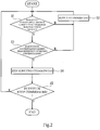
- Fig. 2 is a diagram showing the control flow of the water electrolysis system of Fig. 1 .
- the controller 7 determines whether or not the amount of electric power supplied to the water electrolysis tank 2 is larger than the reference electric power amount (S1).
- the controller 7 determines whether or not the hydrogen concentration is higher than the reference hydrogen concentration (S3).
- the reference electric power amount and the reference hydrogen concentration are set in advance by an operator and can be suitably set.
- the controller 7 determines in S1 that the amount of electric power supplied to the water electrolysis tank 2 is not larger than the reference electric power amount (i.e., the amount of electric power supplied to the water electrolysis tank 2 is the reference electric power amount or less) or when the controller 7 determines in S3 that the hydrogen concentration is not higher than the reference hydrogen concentration (i.e., the hydrogen concentration is the reference hydrogen concentration or less), the controller 7 opens the flow regulating valves V3 and V4 for a certain period of time to supply a certain amount of hydrogen gas to the cathode side gas flowing through a portion of the cathode side gas passage R2 which portion is located upstream of the compressor 4 (herein, upstream of the gas purity analyzer 3) (S2). With this, the oxygen concentration of the cathode side gas is reduced.
- the controller 7 repeatedly performs S1 to S3 until the controller 7 determines in S1 that the amount of electric power supplied to the water electrolysis tank 2 is larger than the reference electric power amount and determines in S3 that the hydrogen concentration is higher than the reference hydrogen concentration.
- the controller 7 determines in S3 that the hydrogen concentration is higher than the reference hydrogen concentration, the controller 7 then closes the flow regulating valves V3 and V4 to stop supplying the hydrogen gas to the cathode side gas (S4).
- the controller 7 determines whether or not a stop of the water electrolysis system 1 is commanded (S5).
- the controller 7 repeatedly performs S1 to S5 until the controller 7 determines in S5 that the stop of the water electrolysis system 1 is commanded.
- the controller 7 terminates the control flow. It should be noted that the order of S1 and S3 in the control flow may be reversed, or only one of S1 and S3 may be performed.
- the hydrogen gas can be supplied to the cathode side gas by opening the flow regulating valves V3 and V4. Further, for example, when it is confirmed based on the monitoring result of the monitoring device that the hydrogen concentration is higher than the reference hydrogen concentration or that the electric power supply amount is larger than the reference electric power amount, the supply of the hydrogen gas to the cathode side gas can be stopped by closing the flow regulating valves V3 and V4.
- the cathode side gas Since the oxygen concentration of the cathode side gas can be reduced by adding the hydrogen gas to the cathode side gas, the cathode side gas is prevented from being discarded. Further, the gas having the same components as the hydrogen produced in the water electrolysis system 1 is added to the cathode side gas. Therefore, the production of the hydrogen in the water electrolysis system 1 can be prevented from being stopped when the hydrogen gas is added to the cathode side gas, and therefore, an operating time of the water electrolysis system 1 can be increased. Thus, the production efficiency of the hydrogen in the water electrolysis system 1 can be improved.
- the flow regulating valves V3 and V4 can be automatically controlled by the controller 7. Therefore, while reducing the burden of the manual operation of the operator, the production efficiency of the hydrogen can be prevented from deteriorating, and the oxygen concentration of the cathode side gas can be reduced.
- the hydrogen supply passage R3 is connected to a portion of the cathode side gas passage R2 which portion is located upstream of the compressor 4. Therefore, before the compressor 4 performs the compression heating of the cathode side gas, the hydrogen concentration of the cathode side gas can be increased, and therefore, the safety of the water electrolysis system 1 can be further improved.
- the hydrogen gas generated by the purifier 5 is supplied through the hydrogen supply passage R3 to the cathode side gas.
- the hydrogen gas stored in the storage tank 6 is supplied through the hydrogen supply passage R3 to the cathode side gas.
- the oxygen gas in the cathode side gas can be effectively removed without providing an additional hydrogen supply source.
- an adequate amount of hydrogen gas can be supplied to the cathode side gas by utilizing the hydrogen gas stored in the storage tank 6.
- the controller 7 may determine in S3 whether or not the oxygen concentration is lower than the predetermined reference oxygen concentration. In this case, when the controller 7 determines in S1 that the amount of electric power supplied to the water electrolysis tank 2 is not larger than the reference electric power amount or determines in S3 that the oxygen concentration is not lower than the reference oxygen concentration (i.e., the oxygen concentration is the reference oxygen concentration or more), the controller 7 executes S2. Further, when the controller 7 determines in S1 that the amount of electric power supplied to the water electrolysis tank 2 is larger than the reference electric power amount and determines in S3 that the oxygen concentration is lower than the reference oxygen concentration, the controller 7 executes S4.
Landscapes
- Chemical & Material Sciences (AREA)
- Engineering & Computer Science (AREA)
- Chemical Kinetics & Catalysis (AREA)
- Electrochemistry (AREA)
- Materials Engineering (AREA)
- Metallurgy (AREA)
- Organic Chemistry (AREA)
- Automation & Control Theory (AREA)
- Inorganic Chemistry (AREA)
- Analytical Chemistry (AREA)
- Electrolytic Production Of Non-Metals, Compounds, Apparatuses Therefor (AREA)
Abstract
Description
- The present invention relates to a water electrolysis system and a method of operating the water electrolysis system.
- For example, known is a water electrolysis system which stores renewable energy, such as wind power, by producing hydrogen from the renewable energy and by which the renewable energy is stably usable. The water electrolysis system includes a water electrolysis tank. The water electrolysis tank includes: an anode chamber configured to electrolyze water to generate an oxygen gas; a cathode chamber configured to electrolyze water to generate a hydrogen gas; and a diaphragm arranged between the anode chamber and the cathode chamber.
-
PTL 1 discloses a hydrogen/oxygen gas generator capable of preventing a case where one of the hydrogen gas and the oxygen gas flows through the diaphragm to be mixed with the other of the hydrogen gas and the oxygen gas. - PTL 1: Japanese Laid-Open Patent Application Publication No.
2006-131957 -
PTL 1 does not consider how to deal with a case where the hydrogen gas and the oxygen gas are mixed with each other in the hydrogen/oxygen gas generator. - An object of the present invention is to, even when an oxygen gas generated at an anode side in a water electrolysis system configured to produce hydrogen flows through a diaphragm to be mixed with a hydrogen gas generated at a cathode side, and this increases an oxygen concentration of the mixture gas, safely reduce the oxygen concentration of the mixture gas. Another object of the present invention is to improve production efficiency of the hydrogen by preventing a case of discarding the hydrogen gas that does not satisfy purity due to the mixing with the oxygen.
- To solve the above problems, a water electrolysis system according to one aspect of the present invention includes: a water electrolysis tank including an anode chamber including an anode therein and configured to electrolyze water by electric power to generate an oxygen gas, the electric power being supplied from an outside, a cathode chamber including a cathode therein and configured to electrolyze the water by the electric power to generate a hydrogen gas, and a diaphragm arranged between the anode chamber and the cathode chamber; a cathode side gas passage through which a cathode side gas discharged from the cathode chamber and containing the hydrogen gas flows; a monitoring device configured to monitor at least one of a hydrogen concentration of the cathode side gas in the cathode side gas passage, an oxygen concentration of the cathode side gas in the cathode side gas passage, and an amount of electric power supplied to the water electrolysis tank; a hydrogen supply passage through which the hydrogen gas is supplied to the cathode side gas in the cathode side gas passage to increase the hydrogen concentration of the cathode side gas; and a flow regulating valve configured to regulate a flow rate of the hydrogen gas supplied through the hydrogen supply passage to the cathode side gas.
- According to the above configuration, for example, when it is confirmed based on a monitoring result of the monitoring device that the hydrogen concentration of the cathode side gas flowing through the cathode side gas passage is the reference hydrogen concentration or less, the oxygen concentration of the cathode side gas flowing through the cathode side gas passage is the reference oxygen concentration or more, or the amount of electric power supplied to the water electrolysis tank is the reference electric power amount or less, the hydrogen gas can be supplied to the cathode side gas by opening the flow regulating valve. Further, for example, when it is confirmed based on the monitoring result of the monitoring device that the hydrogen concentration is higher than the reference hydrogen concentration, the oxygen concentration is lower than the reference oxygen concentration, or the amount of electric power supplied is larger than the reference electric power amount, the supply of the hydrogen gas to the cathode side gas can be stopped by closing the flow regulating valve.
- Therefore, in the water electrolysis system, even when the oxygen gas generated at the anode side flows through the diaphragm to be mixed with the cathode side gas generated at the cathode side and containing the hydrogen gas, and this increases the oxygen concentration of the cathode side gas, the oxygen concentration of the cathode side gas can be safely reduced.
- Since the oxygen concentration of the cathode side gas can be reduced by adding the hydrogen gas to the cathode side gas, the cathode side gas is prevented from being discarded. Further, the gas having the same components as the hydrogen produced in the water electrolysis system is added to the cathode side gas. Therefore, the production of the hydrogen in the water electrolysis system can be prevented from being stopped when the hydrogen gas is added to the cathode side gas, and therefore, an operating time of the water electrolysis system can be increased. Thus, the production efficiency of the hydrogen in the water electrolysis system can be improved.
- The water electrolysis system may further include a controller configured to control the flow regulating valve based on a monitoring result of the monitoring device, wherein: the controller may control the flow regulating valve to stop supplying the hydrogen gas to the cathode side gas when the hydrogen concentration is higher than a reference hydrogen concentration, the oxygen concentration is lower than a reference oxygen concentration, or the amount of electric power supplied is larger than a reference electric power amount; and the controller may control the flow regulating valve to supply the hydrogen gas to the cathode side gas when the hydrogen concentration is the reference hydrogen concentration or less, the oxygen concentration is the reference oxygen concentration or more, or the amount of electric power supplied is the reference electric power amount or less.
- According to the above configuration, the flow regulating valve can be automatically controlled by the controller. Therefore, while reducing the burden of the manual operation of the operator, the production efficiency of the hydrogen can be prevented from deteriorating, and the oxygen concentration of the cathode side gas can be reduced.
- The water electrolysis system may further include a compressor configured to compress the cathode side gas, wherein the hydrogen supply passage may be connected to a portion of the cathode side gas passage, the portion being located upstream of the compressor in a flow direction of the cathode side gas. With this, before the compressor performs compression heating of the cathode side gas, the hydrogen concentration of the cathode side gas can be increased, and therefore, the safety of the system can be further improved.
- The water electrolysis system may further include a purifier configured to remove the oxygen gas from the cathode side gas to generate the hydrogen gas from the cathode side gas, wherein the hydrogen gas generated by the purifier may be supplied through the hydrogen supply passage to the cathode side gas. The water electrolysis system may further include a storage tank configured to store the hydrogen gas generated by the purifier, wherein the hydrogen gas stored in the storage tank may be supplied through the hydrogen supply passage to the cathode side gas. With this, the oxygen gas in the cathode side gas can be effectively removed without providing an additional hydrogen supply source.
- A method of operating a water electrolysis system according to another aspect of the present invention is a method of operating a water electrolysis system, the water electrolysis system including: a water electrolysis tank including an anode chamber including an anode therein and configured to electrolyze water by electric power to generate an oxygen gas, the electric power being supplied from an outside, a cathode chamber including a cathode therein and configured to electrolyze the water by the electric power to generate a hydrogen gas, and a diaphragm arranged between the anode chamber and the cathode chamber; a cathode side gas passage through which a cathode side gas discharged from the cathode chamber and containing the hydrogen gas flows; a monitoring device configured to monitor at least one of a hydrogen concentration of the cathode side gas in the cathode side gas passage, an oxygen concentration of the cathode side gas in the cathode side gas passage, and an amount of electric power supplied to the water electrolysis tank; a hydrogen supply passage through which the hydrogen gas is supplied to the cathode side gas in the cathode side gas passage to increase the hydrogen concentration of the cathode side gas; and a flow regulating valve configured to regulate a flow rate of the hydrogen gas supplied through the hydrogen supply passage to the cathode side gas, the method including controlling the flow regulating valve to (i) stop supplying the hydrogen gas to the cathode side gas when the hydrogen concentration is higher than a reference hydrogen concentration, the oxygen concentration is lower than a reference oxygen concentration, or the amount of electric power supplied to the water electrolysis tank is larger than a reference electric power amount and (ii) supply the hydrogen gas to the cathode side gas when the hydrogen concentration is the reference hydrogen concentration or less, the oxygen concentration is the reference oxygen concentration or more, or the amount of electric power supplied is the reference electric power amount or less.
- According to the present invention, in the water electrolysis system configured to produce hydrogen, even when the oxygen gas generated at the anode side flows through the diaphragm to be mixed with the hydrogen gas generated at the cathode side, and this increases the oxygen concentration of the mixture gas, the oxygen concentration of the mixture gas can be safely reduced. Further, discarding the hydrogen gas that does not satisfy purity due to the mixing with the oxygen is prevented, and therefore, the production efficiency of the hydrogen can be improved.
-
-
Fig. 1 is a schematic configuration diagram of a water electrolysis system according to an embodiment. -
Fig. 2 is a diagram showing a control flow of the water electrolysis system ofFig. 1 . - Hereinafter, an embodiment will be explained with reference to the drawings.
-
Fig. 1 is a schematic configuration diagram of awater electrolysis system 1 according to the embodiment. Thewater electrolysis system 1 includes awater electrolysis tank 2, agas purity analyzer 3, a compressor 4, apurifier 5, astorage tank 6, acontroller 7, an anode side gas passage R1, a cathode side gas passage R2, a hydrogen supply passage R3, a nitrogen supply passage R4, a cathode side gas discharge passage R5, flow regulating valves V1 to V4, anddischarge ports - The
water electrolysis tank 2 is supplied with electric power (DC power) from an outside. The electric power is, for example, electric power generated from renewable energy, such as wind power, but is not limited to this. Thewater electrolysis tank 2 includes ananode 8, a cathode 9, and adiaphragm 10. Thewater electrolysis tank 2 further includes ananode chamber 2a and acathode chamber 2b. Theanode 8 is arranged in theanode chamber 2a, and theanode chamber 2a electrolyzes water to generate an oxygen gas by the electric power supplied from the outside. An anode side gas containing the oxygen gas is discharged from theanode chamber 2a. The cathode 9 is arranged in thecathode chamber 2b, and thecathode chamber 2b electrolyzes water to generate a hydrogen gas by the electric power. A cathode side gas containing the hydrogen gas is discharged from thecathode chamber 2b. Thediaphragm 10 is arranged between theanode chamber 2a and thecathode chamber 2b. - The
water electrolysis tank 2 of the present embodiment is, for example, an alkaline water electrolysis type, and an electrolytic solution containing potassium hydroxide (KOH) is stored in theanode chamber 2a and thecathode chamber 2b. While thewater electrolysis system 1 is operating, electrolytes in the electrolytic solution move in theanode chamber 2a and thecathode chamber 2b through thediaphragm 10, and water is electrolyzed. - The
water electrolysis tank 2 is not limited to the alkaline water electrolysis type and may be the other type, such as a solid polymer type. SinceFig. 1 schematically shows thewater electrolysis tank 2, oneanode chamber 2a and onecathode chamber 2b are shown. However, the number ofanode chambers 2a and the number ofcathode chambers 2b are not limited. For example, in thewater electrolysis tank 2, a plurality ofanode chambers 2a and a plurality ofcathode chambers 2b may be alternately arranged through a plurality ofdiaphragms 10. - The anode side gas discharged from the
anode chamber 2a and containing the oxygen gas flows through the anode side gas passage R1. An upstream end portion of the anode side gas passage R1 is connected to theanode chamber 2a. Thedischarge port 11 is provided at a downstream end portion of the anode side gas passage R1. The anode side gas is separated from the electrolytic solution, flows through the anode side gas passage R1, and is then discharged through thedischarge port 11 to an outside of thewater electrolysis system 1. - The cathode side gas discharged from the
cathode chamber 2b and containing the hydrogen gas flows through the cathode side gas passage R2. An upstream end portion of the cathode side gas passage R2 is connected to thecathode chamber 2b. A downstream end portion of the cathode side gas passage R2 is connected to thestorage tank 6. The cathode side gas is separated from the electrolytic solution and flows through the cathode side gas passage R2. - The
gas purity analyzer 3 analyzes hydrogen purity of the cathode side gas flowing through a portion of the cathode side gas passage R2 which portion is located upstream of the compressor 4 in a flow direction of the cathode side gas (hereinafter simply referred to as "upstream of the compressor 4"). Specifically, thegas purity analyzer 3 measures at least one of a hydrogen concentration and oxygen concentration (herein, the hydrogen concentration as one example) of the cathode side gas separated from the electrolytic solution and flowing through the portion of the cathode side gas passage R2 which portion is located upstream of the compressor 4. A measurement result of thegas purity analyzer 3 is transmitted to thecontroller 7. - The compressor 4 compresses the cathode side gas. In the present embodiment, the compressor 4 performs compression heating of the cathode side gas. The
purifier 5 is arranged at a portion of the cathode side gas passage R2 which portion is located downstream of the compressor 4 in the flow direction of the cathode side gas (hereinafter simply referred to as "downstream of the compressor 4"). Thepurifier 5 removes the oxygen gas from the cathode side gas to generate the hydrogen gas from the cathode side gas. - The
storage tank 6 is arranged at a portion of the cathode side gas passage R2 which portion is located downstream of thepurifier 5. Thestorage tank 6 stores the hydrogen gas generated by thepurifier 5. Thestorage tank 6 may store liquid hydrogen. In this case, a liquefier needs to be provided at a portion of the cathode side gas passage R2 which portion is located between thepurifier 5 and thestorage tank 6. - The nitrogen supply passage R4 is provided so as to be able to supply a nitrogen gas to the cathode side gas flowing through the cathode side gas passage R2. An upstream end portion of the nitrogen supply passage R4 is connected to a
nitrogen source 13. A downstream end portion of the nitrogen supply passage R4 is connected to a portion of the cathode side gas passage R2 which portion is located upstream of thegas purity analyzer 3. - The flow regulating valve V1 is provided at a portion of the nitrogen supply passage R4. The flow regulating valve V1 regulates the flow rate of the nitrogen gas supplied through the nitrogen supply passage R4 to the cathode side gas. When the flow regulating valve V1 opens, the nitrogen gas is supplied to the cathode side gas flowing through the cathode side gas passage R2, and this reduces the hydrogen concentration and oxygen concentration of the cathode side gas. With this, the cathode side gas can be inactivated, and maintenance work of the
water electrolysis system 1 and the like can be safely performed. - The cathode side gas discharge passage R5 is provided so as to be able to discharge the cathode side gas from the cathode side gas passage R2 to the outside of the
water electrolysis system 1. An upstream end portion of the cathode side gas discharge passage R5 is connected to a portion of the cathode side gas passage R2 which portion is located downstream of thegas purity analyzer 3 and upstream of the compressor 4. Thedischarge port 12 is provided at a downstream end portion of the cathode side gas discharge passage R5. - The flow regulating valve V2 is provided at a portion of the cathode side gas discharge passage R5. The flow regulating valve V2 regulates the flow rate of the cathode side gas flowing through the cathode side gas discharge passage R5. When the flow regulating valve V2 opens, the cathode side gas flows through the cathode side gas discharge passage R5 to be discharged through the
discharge port 12 to the outside of thewater electrolysis system 1. - The hydrogen supply passage R3 is provided so as to be able to supply the hydrogen gas to the cathode side gas such that the hydrogen concentration of the cathode side gas flowing through the cathode side gas passage R2 increases. The hydrogen gas flowing through the hydrogen supply passage R3 is, for example, the hydrogen gas stored in the
storage tank 6. The hydrogen supply passage R3 is connected to a portion of the cathode side gas passage R2 which portion is located upstream of the compressor 4. In the present embodiment, an upstream end portion of the hydrogen supply passage R3 is connected to thestorage tank 6. A downstream end portion of the hydrogen supply passage R3 is connected to a portion of the cathode side gas passage R2 which portion is located upstream of thegas purity analyzer 3. - The flow regulating valves V3 and V4 are provided at portions of the hydrogen supply passage R3. Each of the flow regulating valves V3 and V4 regulates the flow rate of the hydrogen gas supplied through the hydrogen supply passage R3 to the cathode side gas. The flow regulating valve V3 is provided at a portion of the hydrogen supply passage R3. The flow regulating valve V4 is provided at a portion of the hydrogen supply passage R3 which portion is located downstream of the flow regulating valve V3 in the flow direction of the hydrogen gas. When the flow regulating valves V3 and V4 open, the hydrogen gas is supplied to the cathode side gas flowing through the cathode side gas passage R2, and this reduces the oxygen concentration of the cathode side gas.
- For example, the flow regulating valves V1 to V3 are electromagnetic flow regulating valves, and the flow regulating valve V4 is a pressure-reducing flow regulating valve. However, the types of the flow regulating valves V1 to V4 are not limited. Further, the number of flow regulating valves provided at the hydrogen supply passage R3 is not limited, and for example, only one of the flow regulating valves V3 and V4 may be provided at the hydrogen supply passage R3. Further, for example, the hydrogen gas flowing through the hydrogen supply passage R3 may be the hydrogen produced by the
water electrolysis system 1 or the hydrogen gas supplied from a hydrogen cylinder. - The
water electrolysis system 1 includes a monitoring device. The monitoring device monitors at least one of: the hydrogen concentration of the cathode side gas in the cathode side gas passage R2 (hereinafter may be simply referred to as a "hydrogen concentration"); the oxygen concentration of the cathode side gas in the cathode side gas passage R2 (hereinafter may be simply referred to as an "oxygen concentration"); and the amount of electric power supplied to the water electrolysis tank 2 (hereinafter may be simply referred to as an "electric power supply amount"). In the present embodiment, the monitoring device monitors the hydrogen concentration and the electric power supply amount. For example, the monitoring device monitors the hydrogen concentration of the cathode side gas in a portion of the cathode side gas passage R2 which portion is located upstream of the compressor 4. Further, the monitoring device monitors the hydrogen concentration based on a measurement result of thegas purity analyzer 3. Furthermore, the monitoring device monitors the electric power supply amount based on a measured value of an electric power meter provided at thewater electrolysis system 1. - The
gas purity analyzer 3 and the flow regulating valves V1 to V4 are connected to thecontroller 7. Thecontroller 7 controls the flow regulating valves V1 and V2 at predetermined timings. Further, thecontroller 7 controls the flow regulating valves V3 and V4 based on a monitoring result of the monitoring device. In the present embodiment, as one example, thecontroller 7 also serves as the monitoring device. However, the monitoring device may be provided separately from thecontroller 7. - The
controller 7 is, for example, a computer including a CPU, a RAM, and a ROM. The ROM stores a predetermined control program. The CPU monitors the hydrogen concentration and the electric power supply amount and controls the flow regulating valves V3 and V4 by the control program. - In some cases, in the water electrolysis system, the oxygen gas generated at the anode side flows through the diaphragm to be mixed with the cathode side gas generated at the cathode side and containing the hydrogen gas, and as a result, the cathode side gas becomes the mixture gas. The oxygen gas in the cathode side gas is removed by the purifier. The oxygen concentration of the cathode side gas increases as the electric power supply amount decreases. When the electric power supply amount becomes smaller than a certain amount, the oxygen concentration of the cathode side gas significantly increases in some cases. In conventional cases, when the oxygen concentration of the cathode side gas exceeds a specified value, for example, the oxygen concentration of the cathode side gas is reduced by adding the nitrogen gas to the cathode side gas. With this, the safety of the cathode side gas is improved.
- However, since it is difficult to separate the hydrogen gas and the nitrogen gas after the hydrogen gas and the nitrogen gas are mixed with each other, the cathode side gas to which the nitrogen gas is added is discharged to an outside of the water electrolysis system. By this discharging, a part of the produced hydrogen is discarded. Further, even when the nitrogen gas is added to the cathode side gas, and then, the electric power supply amount recovers, restarting the production of the hydrogen in the water electrolysis system is difficult until the nitrogen gas remaining in the cathode side gas passage is adequately removed.
- Further, according to electric power generation by utilizing renewable energy, the amount of electric power generated easily changes depending on conditions, such as weather. Therefore, when operating the water electrolysis system by utilizing the renewable energy, the electric power supply amount tends to become a specified value or less, and accordingly, the oxygen concentration of the cathode side gas tends to exceed a specified value. With this, the amount of hydrogen discarded after the nitrogen gas is added may increase.
- On the other hand, as described below, the
water electrolysis system 1 controls the flow regulating valves V3 and V4 to stop supplying the hydrogen gas to the cathode side gas when (i) the hydrogen concentration is higher than a predetermined reference hydrogen concentration, (ii) the oxygen concentration is lower than a predetermined reference oxygen concentration, or (iii) the amount of electric power supplied to thewater electrolysis tank 2 is larger than a predetermined reference electric power amount, and controls the flow regulating valves V3 and V4 to supply the hydrogen gas to the cathode side gas when (i) the hydrogen concentration is the reference hydrogen concentration or less, (ii) the oxygen concentration is the reference oxygen concentration or more, or (iii) the amount of electric power supplied to thewater electrolysis tank 2 is the reference electric power amount or less. The oxygen gas contained in the cathode side gas is removed by thepurifier 5. With this, according to thewater electrolysis system 1, the amount of hydrogen discarded after the nitrogen gas is added can be reduced, and the hydrogen can be produced with high production efficiency. - Hereinafter, a control flow of the
water electrolysis system 1 will be explained.Fig. 2 is a diagram showing the control flow of the water electrolysis system ofFig. 1 . In thewater electrolysis system 1 in operation, thecontroller 7 determines whether or not the amount of electric power supplied to thewater electrolysis tank 2 is larger than the reference electric power amount (S1). When thecontroller 7 determines in S1 that the amount of electric power supplied to thewater electrolysis tank 2 is larger than the reference electric power amount, thecontroller 7 then determines whether or not the hydrogen concentration is higher than the reference hydrogen concentration (S3). The reference electric power amount and the reference hydrogen concentration are set in advance by an operator and can be suitably set. - When the
controller 7 determines in S1 that the amount of electric power supplied to thewater electrolysis tank 2 is not larger than the reference electric power amount (i.e., the amount of electric power supplied to thewater electrolysis tank 2 is the reference electric power amount or less) or when thecontroller 7 determines in S3 that the hydrogen concentration is not higher than the reference hydrogen concentration (i.e., the hydrogen concentration is the reference hydrogen concentration or less), thecontroller 7 opens the flow regulating valves V3 and V4 for a certain period of time to supply a certain amount of hydrogen gas to the cathode side gas flowing through a portion of the cathode side gas passage R2 which portion is located upstream of the compressor 4 (herein, upstream of the gas purity analyzer 3) (S2). With this, the oxygen concentration of the cathode side gas is reduced. - The
controller 7 repeatedly performs S1 to S3 until thecontroller 7 determines in S1 that the amount of electric power supplied to thewater electrolysis tank 2 is larger than the reference electric power amount and determines in S3 that the hydrogen concentration is higher than the reference hydrogen concentration. When thecontroller 7 determines in S3 that the hydrogen concentration is higher than the reference hydrogen concentration, thecontroller 7 then closes the flow regulating valves V3 and V4 to stop supplying the hydrogen gas to the cathode side gas (S4). - The
controller 7 then determines whether or not a stop of thewater electrolysis system 1 is commanded (S5). Thecontroller 7 repeatedly performs S1 to S5 until thecontroller 7 determines in S5 that the stop of thewater electrolysis system 1 is commanded. When thecontroller 7 determines in S5 that the stop of thewater electrolysis system 1 is commanded, thecontroller 7 terminates the control flow. It should be noted that the order of S1 and S3 in the control flow may be reversed, or only one of S1 and S3 may be performed. - As explained above, in the
water electrolysis system 1, for example, when it is confirmed based on the monitoring result of the monitoring device that the hydrogen concentration of the cathode side gas flowing through the cathode side gas passage R2 is the reference hydrogen concentration or less or that the amount of electric power supplied to thewater electrolysis tank 2 is the reference electric power amount or less, the hydrogen gas can be supplied to the cathode side gas by opening the flow regulating valves V3 and V4. Further, for example, when it is confirmed based on the monitoring result of the monitoring device that the hydrogen concentration is higher than the reference hydrogen concentration or that the electric power supply amount is larger than the reference electric power amount, the supply of the hydrogen gas to the cathode side gas can be stopped by closing the flow regulating valves V3 and V4. - Therefore, in the
water electrolysis system 1, even when the oxygen gas generated at theanode 8 flows through thediaphragm 10 to be mixed with the cathode side gas generated at the cathode 9 and containing the hydrogen gas, and this increases the oxygen concentration of the cathode side gas, the oxygen concentration of the cathode side gas can be safely reduced. - Since the oxygen concentration of the cathode side gas can be reduced by adding the hydrogen gas to the cathode side gas, the cathode side gas is prevented from being discarded. Further, the gas having the same components as the hydrogen produced in the
water electrolysis system 1 is added to the cathode side gas. Therefore, the production of the hydrogen in thewater electrolysis system 1 can be prevented from being stopped when the hydrogen gas is added to the cathode side gas, and therefore, an operating time of thewater electrolysis system 1 can be increased. Thus, the production efficiency of the hydrogen in thewater electrolysis system 1 can be improved. - Further, according to the
water electrolysis system 1, the flow regulating valves V3 and V4 can be automatically controlled by thecontroller 7. Therefore, while reducing the burden of the manual operation of the operator, the production efficiency of the hydrogen can be prevented from deteriorating, and the oxygen concentration of the cathode side gas can be reduced. - Further, the hydrogen supply passage R3 is connected to a portion of the cathode side gas passage R2 which portion is located upstream of the compressor 4. Therefore, before the compressor 4 performs the compression heating of the cathode side gas, the hydrogen concentration of the cathode side gas can be increased, and therefore, the safety of the
water electrolysis system 1 can be further improved. - The hydrogen gas generated by the
purifier 5 is supplied through the hydrogen supply passage R3 to the cathode side gas. Specifically, the hydrogen gas stored in thestorage tank 6 is supplied through the hydrogen supply passage R3 to the cathode side gas. With this, the oxygen gas in the cathode side gas can be effectively removed without providing an additional hydrogen supply source. Further, an adequate amount of hydrogen gas can be supplied to the cathode side gas by utilizing the hydrogen gas stored in thestorage tank 6. - The
controller 7 may determine in S3 whether or not the oxygen concentration is lower than the predetermined reference oxygen concentration. In this case, when thecontroller 7 determines in S1 that the amount of electric power supplied to thewater electrolysis tank 2 is not larger than the reference electric power amount or determines in S3 that the oxygen concentration is not lower than the reference oxygen concentration (i.e., the oxygen concentration is the reference oxygen concentration or more), thecontroller 7 executes S2. Further, when thecontroller 7 determines in S1 that the amount of electric power supplied to thewater electrolysis tank 2 is larger than the reference electric power amount and determines in S3 that the oxygen concentration is lower than the reference oxygen concentration, thecontroller 7 executes S4. - The present invention is not limited to the above embodiment, and modifications, additions, and eliminations with respect to the configurations and methods of the present invention may be made within the scope of the present invention.
-
- R2
- cathode side gas passage
- R3
- hydrogen supply passage
- V3, V4
- flow regulating valve
- 1
- water electrolysis system
- 2
- water electrolysis tank
- 2a
- anode chamber
- 2b
- cathode chamber
- 4
- compressor
- 5
- purifier
- 6
- storage tank
- 7
- controller
- 8
- anode
- 9
- cathode
- 10
- diaphragm
Claims (6)
- A water electrolysis system comprising:a water electrolysis tank includingan anode chamber including an anode therein and configured to electrolyze water by electric power to generate an oxygen gas, the electric power being supplied from an outside,a cathode chamber including a cathode therein and configured to electrolyze the water by the electric power to generate a hydrogen gas, anda diaphragm arranged between the anode chamber and the cathode chamber;a cathode side gas passage through which a cathode side gas discharged from the cathode chamber and containing the hydrogen gas flows;a monitoring device configured to monitor at least one of a hydrogen concentration of the cathode side gas in the cathode side gas passage, an oxygen concentration of the cathode side gas in the cathode side gas passage, and an amount of electric power supplied to the water electrolysis tank;a hydrogen supply passage through which the hydrogen gas is supplied to the cathode side gas in the cathode side gas passage to increase the hydrogen concentration of the cathode side gas; anda flow regulating valve configured to regulate a flow rate of the hydrogen gas supplied through the hydrogen supply passage to the cathode side gas.
- The water electrolysis system according to claim 1, further comprising a controller configured to control the flow regulating valve based on a monitoring result of the monitoring device, wherein:the controller controls the flow regulating valve to stop supplying the hydrogen gas to the cathode side gas when the hydrogen concentration is higher than a reference hydrogen concentration, the oxygen concentration is lower than a reference oxygen concentration, or the amount of electric power supplied is larger than a reference electric power amount; andthe controller controls the flow regulating valve to supply the hydrogen gas to the cathode side gas when the hydrogen concentration is the reference hydrogen concentration or less, the oxygen concentration is the reference oxygen concentration or more, or the amount of electric power supplied is the reference electric power amount or less.
- The water electrolysis system according to claim 1 or 2, further comprising a compressor configured to compress the cathode side gas, wherein
the hydrogen supply passage is connected to a portion of the cathode side gas passage, the portion being located upstream of the compressor in a flow direction of the cathode side gas. - The water electrolysis system according to any one of claims 1 to 3, further comprising a purifier configured to remove the oxygen gas from the cathode side gas to generate the hydrogen gas from the cathode side gas, wherein
the hydrogen gas generated by the purifier is supplied through the hydrogen supply passage to the cathode side gas. - The water electrolysis system according to claim 4, further comprising a storage tank configured to store the hydrogen gas generated by the purifier, wherein
the hydrogen gas stored in the storage tank is supplied through the hydrogen supply passage to the cathode side gas. - A method of operating a water electrolysis system,
the water electrolysis system comprising:a water electrolysis tank includingan anode chamber including an anode therein and configured to electrolyze water by electric power to generate an oxygen gas, the electric power being supplied from an outside,a cathode chamber including a cathode therein and configured to electrolyze the water by the electric power to generate a hydrogen gas, anda diaphragm arranged between the anode chamber and the cathode chamber;a cathode side gas passage through which a cathode side gas discharged from the cathode chamber and containing the hydrogen gas flows;a monitoring device configured to monitor at least one of a hydrogen concentration of the cathode side gas in the cathode side gas passage, an oxygen concentration of the cathode side gas in the cathode side gas passage, and an amount of electric power supplied to the water electrolysis tank;a hydrogen supply passage through which the hydrogen gas is supplied to the cathode side gas in the cathode side gas passage to increase the hydrogen concentration of the cathode side gas; anda flow regulating valve configured to regulate a flow rate of the hydrogen gas supplied through the hydrogen supply passage to the cathode side gas,the method comprisingcontrolling the flow regulating valve to (i) stop supplying the hydrogen gas to the cathode side gas when the hydrogen concentration is higher than a reference hydrogen concentration, the oxygen concentration is lower than a reference oxygen concentration, or the amount of electric power supplied to the water electrolysis tank is larger than a reference electric power amount and (ii) supply the hydrogen gas to the cathode side gas when the hydrogen concentration is the reference hydrogen concentration or less, the oxygen concentration is the reference oxygen concentration or more, or the amount of electric power supplied is the reference electric power amount or less.
Applications Claiming Priority (2)
| Application Number | Priority Date | Filing Date | Title |
|---|---|---|---|
| JP2017032160A JP6899665B2 (en) | 2017-02-23 | 2017-02-23 | How to operate the water electrolysis system and the water electrolysis system |
| PCT/JP2018/005326 WO2018155308A1 (en) | 2017-02-23 | 2018-02-15 | Water electrolysis system and method for operating water electrolysis system |
Publications (3)
| Publication Number | Publication Date |
|---|---|
| EP3591096A1 true EP3591096A1 (en) | 2020-01-08 |
| EP3591096A4 EP3591096A4 (en) | 2020-12-16 |
| EP3591096B1 EP3591096B1 (en) | 2021-10-13 |
Family
ID=63252656
Family Applications (1)
| Application Number | Title | Priority Date | Filing Date |
|---|---|---|---|
| EP18756898.5A Active EP3591096B1 (en) | 2017-02-23 | 2018-02-15 | Water electrolysis system and method of operating water electrolysis system |
Country Status (9)
| Country | Link |
|---|---|
| US (1) | US11060198B2 (en) |
| EP (1) | EP3591096B1 (en) |
| JP (1) | JP6899665B2 (en) |
| CN (1) | CN110023543B (en) |
| AU (1) | AU2018223580B2 (en) |
| CA (1) | CA3042173C (en) |
| ES (1) | ES2899400T3 (en) |
| PT (1) | PT3591096T (en) |
| WO (1) | WO2018155308A1 (en) |
Families Citing this family (11)
| Publication number | Priority date | Publication date | Assignee | Title |
|---|---|---|---|---|
| WO2020095664A1 (en) * | 2018-11-05 | 2020-05-14 | 旭化成株式会社 | Method for manufacturing hydrogen |
| JP7426817B2 (en) * | 2019-12-26 | 2024-02-02 | Eneos株式会社 | Organic hydride generation system, control device for organic hydride generation system, and control method for organic hydride generation system |
| CN112522727B (en) * | 2020-12-02 | 2021-11-12 | 上海毅镤新能源科技有限公司 | Hydrogen production plant |
| CN112760679B (en) * | 2021-01-27 | 2025-02-28 | 约翰考克利尔公司 | Differential pressure adjusting method and device |
| CN114686905B (en) * | 2022-03-30 | 2023-04-25 | 东方电气集团东方锅炉股份有限公司 | Method and system for monitoring and early warning cathode-anode channeling of water electrolysis tank |
| CN115747878A (en) * | 2022-11-14 | 2023-03-07 | 阳光氢能科技有限公司 | Water electrolysis hydrogen production device and gas purity detection method thereof |
| CN115976572B (en) * | 2022-12-22 | 2023-08-08 | 北京科技大学 | Electrolyzer gas purity control method, system, device and storage medium |
| US20250066934A1 (en) * | 2023-08-21 | 2025-02-27 | Alchemr, Inc. | Methods of Operating a Water Electrolyzer |
| DE102023208576A1 (en) * | 2023-09-06 | 2025-03-06 | Robert Bosch Gesellschaft mit beschränkter Haftung | Method for operating an electrolysis plant, electrolysis plant |
| CN117776425A (en) * | 2023-11-24 | 2024-03-29 | 深圳市至臻生物科技有限公司 | Hydrogen-rich water conversion and inhalation method, device and electronic equipment based on rehabilitation treatment |
| JP7728384B1 (en) * | 2024-02-14 | 2025-08-22 | 本田技研工業株式会社 | Water electrolysis system |
Family Cites Families (22)
| Publication number | Priority date | Publication date | Assignee | Title |
|---|---|---|---|---|
| JP2905705B2 (en) * | 1994-10-25 | 1999-06-14 | 神鋼パンテツク株式会社 | Reactor water oxygen concentration control device |
| JP2851544B2 (en) * | 1994-11-28 | 1999-01-27 | 神鋼パンテツク株式会社 | Method and apparatus for removing residual voltage from water electrolysis cell |
| US6146518A (en) * | 1999-09-01 | 2000-11-14 | Stuart Energy Systems Inc. | Pressure differential control in an electrolytic cell |
| JP3717424B2 (en) * | 2000-08-18 | 2005-11-16 | 株式会社神鋼環境ソリューション | Hydrogen and oxygen supply system |
| CN100523306C (en) * | 2000-07-26 | 2009-08-05 | 株式会社神钢环境舒立净 | Hydrogen/oxygen supply system |
| DE10258525A1 (en) * | 2002-12-14 | 2004-07-01 | GHW Gesellschaft für Hochleistungselektrolyseure zur Wasserstofferzeugung mbH | Pressure electrolyzer and method for switching off a pressure electrolyzer |
| JP2004148116A (en) * | 2003-10-21 | 2004-05-27 | Kobelco Eco-Solutions Co Ltd | Oxygen supply system |
| JP4751594B2 (en) | 2004-11-05 | 2011-08-17 | 株式会社神鋼環境ソリューション | Hydrogen / oxygen gas generator and operation method thereof |
| JP2009195884A (en) * | 2008-02-25 | 2009-09-03 | Purotekku:Kk | Apparatus for generating electrolytic water |
| CN101705497B (en) * | 2009-11-06 | 2011-05-18 | 上海神开石油化工装备股份有限公司 | Adjusting method of hydrogen generator with adjustable pressure |
| JP5192004B2 (en) * | 2010-02-12 | 2013-05-08 | 本田技研工業株式会社 | How to stop water electrolysis system |
| KR101893006B1 (en) * | 2011-10-14 | 2018-10-05 | 삼성전자주식회사 | Apparatus for reducing water by electrolysis and method for controlling the same |
| US20150329977A1 (en) * | 2012-11-19 | 2015-11-19 | Tina Energy Systems S.L. | Pem-type electrolyzer stack for operation at high pressure |
| US9186624B2 (en) * | 2013-06-28 | 2015-11-17 | Nuvera Fuel Cells, Inc. | Methods of producing and providing purified gas using an electrochemical cell |
| CN203834032U (en) * | 2014-04-28 | 2014-09-17 | 赵广庆 | Burner system for generating hydrogen-oxygen mixed gas by electrolyzing water |
| CN203960347U (en) * | 2014-05-29 | 2014-11-26 | 吉林省中涵科技有限公司 | With the hydrogen and oxygen gas mixture generating unit of gas ratio regulatory function |
| TWM503226U (en) * | 2015-03-09 | 2015-06-21 | Hsin-Yung Lin | Gas generator |
| TWI592518B (en) * | 2015-08-11 | 2017-07-21 | Miz股份有限公司 | Hydrogen generating device |
| WO2017056277A1 (en) * | 2015-09-30 | 2017-04-06 | 株式会社 東芝 | Device and system for producing hydrogen |
| CN106367776A (en) * | 2016-11-18 | 2017-02-01 | 上海顶信医疗设备股份有限公司 | Electrolysis device and gas output equipment used for outputting hydrogen-containing mixed gas and provided with electrolysis device |
| CN106591872B (en) * | 2017-01-25 | 2024-07-26 | 中国人民解放军第二军医大学 | Device and method for preparing hydrogen-oxygen mixed gas |
| WO2018174281A1 (en) * | 2017-03-23 | 2018-09-27 | 旭化成株式会社 | Water electrolysis system, water electrolysis method and method for producing hydrogen |
-
2017
- 2017-02-23 JP JP2017032160A patent/JP6899665B2/en active Active
-
2018
- 2018-02-15 EP EP18756898.5A patent/EP3591096B1/en active Active
- 2018-02-15 PT PT187568985T patent/PT3591096T/en unknown
- 2018-02-15 ES ES18756898T patent/ES2899400T3/en active Active
- 2018-02-15 WO PCT/JP2018/005326 patent/WO2018155308A1/en not_active Ceased
- 2018-02-15 AU AU2018223580A patent/AU2018223580B2/en active Active
- 2018-02-15 CA CA3042173A patent/CA3042173C/en active Active
- 2018-02-15 US US16/345,290 patent/US11060198B2/en active Active
- 2018-02-15 CN CN201880004728.8A patent/CN110023543B/en active Active
Also Published As
| Publication number | Publication date |
|---|---|
| ES2899400T3 (en) | 2022-03-11 |
| US20190271091A1 (en) | 2019-09-05 |
| CN110023543A (en) | 2019-07-16 |
| EP3591096A4 (en) | 2020-12-16 |
| JP2018135580A (en) | 2018-08-30 |
| WO2018155308A1 (en) | 2018-08-30 |
| JP6899665B2 (en) | 2021-07-07 |
| PT3591096T (en) | 2021-11-23 |
| CA3042173C (en) | 2021-06-15 |
| EP3591096B1 (en) | 2021-10-13 |
| CA3042173A1 (en) | 2018-08-30 |
| CN110023543B (en) | 2021-05-25 |
| AU2018223580A1 (en) | 2019-05-30 |
| AU2018223580B2 (en) | 2020-03-12 |
| US11060198B2 (en) | 2021-07-13 |
Similar Documents
| Publication | Publication Date | Title |
|---|---|---|
| EP3591096B1 (en) | Water electrolysis system and method of operating water electrolysis system | |
| CN114134527B (en) | Water electrolysis hydrogen production device and method with multiple electrolytic tanks | |
| JP6826699B2 (en) | Gas production equipment and gas production method | |
| CN112899712A (en) | Water electrolysis hydrogen production device and hydrogen production method | |
| JP7363419B2 (en) | water electrolysis system | |
| CA2271450A1 (en) | Hydrogen fuel replenishment process and apparatus | |
| KR102336533B1 (en) | Apparatus and method for operating an electrolysis with an oxygen depolarized cathode | |
| CN115029733A (en) | System and method for regulating and controlling flow of alkaline liquor of many-to-one water electrolysis hydrogen production device | |
| CN116970990A (en) | Hydrogen production system and method | |
| CN116356346B (en) | Hydrogen production system and hydrogen production system control method | |
| WO2020008687A1 (en) | Water electrolysis system and water electrolysis method | |
| CN116121792A (en) | Direct hydrogen production method by photovoltaic power generation | |
| CN119800400B (en) | An electro-hydrogen production system and its control method | |
| CA3178248C (en) | Electrolytic cell, method for operating a cell of this type and electrolyser | |
| CN221297086U (en) | A control system for hydrogen content in oxygen under low load condition of alkaline water electrolysis hydrogen production system | |
| US6528192B2 (en) | Residual fuel dissipation for a fuel cell stack | |
| JP2012087396A (en) | Method for controlling high pressure water electrolysis system | |
| CN220520647U (en) | Alkaline electrolyzed water hydrogen production system with oxygen separator protection function | |
| KR20020071102A (en) | A method for controlling a hydrogen and oxygen generator | |
| EP4606932A1 (en) | An electrolyser system and a method for operating the electrolyser system | |
| KR20260029968A (en) | Electrolysis system and controlling method of thereof | |
| KR20260029969A (en) | Electrolysis system and controlling method of thereof | |
| CN122013213A (en) | Alkaline solution secondary separation circulation system of alkaline electrolytic tank and working method thereof | |
| CN121826801A (en) | Precise regulation and safety interlocking device and method for offshore hydrogen production equipment | |
| CN117187878A (en) | A system and method for controlling the hydrogen content in oxygen under low load conditions in an alkaline electrolytic water hydrogen production system |
Legal Events
| Date | Code | Title | Description |
|---|---|---|---|
| STAA | Information on the status of an ep patent application or granted ep patent |
Free format text: STATUS: THE INTERNATIONAL PUBLICATION HAS BEEN MADE |
|
| PUAI | Public reference made under article 153(3) epc to a published international application that has entered the european phase |
Free format text: ORIGINAL CODE: 0009012 |
|
| STAA | Information on the status of an ep patent application or granted ep patent |
Free format text: STATUS: REQUEST FOR EXAMINATION WAS MADE |
|
| 17P | Request for examination filed |
Effective date: 20190627 |
|
| AK | Designated contracting states |
Kind code of ref document: A1 Designated state(s): AL AT BE BG CH CY CZ DE DK EE ES FI FR GB GR HR HU IE IS IT LI LT LU LV MC MK MT NL NO PL PT RO RS SE SI SK SM TR |
|
| AX | Request for extension of the european patent |
Extension state: BA ME |
|
| DAV | Request for validation of the european patent (deleted) | ||
| DAX | Request for extension of the european patent (deleted) | ||
| A4 | Supplementary search report drawn up and despatched |
Effective date: 20201116 |
|
| RIC1 | Information provided on ipc code assigned before grant |
Ipc: C01B 3/50 20060101ALI20201110BHEP Ipc: C25B 1/10 20060101ALI20201110BHEP Ipc: C25B 15/02 20060101AFI20201110BHEP Ipc: C01B 3/02 20060101ALI20201110BHEP Ipc: C25B 15/08 20060101ALI20201110BHEP |
|
| GRAP | Despatch of communication of intention to grant a patent |
Free format text: ORIGINAL CODE: EPIDOSNIGR1 |
|
| STAA | Information on the status of an ep patent application or granted ep patent |
Free format text: STATUS: GRANT OF PATENT IS INTENDED |
|
| RIC1 | Information provided on ipc code assigned before grant |
Ipc: C25B 15/02 20210101AFI20210416BHEP Ipc: C25B 15/08 20060101ALI20210416BHEP Ipc: C25B 9/19 20210101ALI20210416BHEP Ipc: C25B 9/73 20210101ALI20210416BHEP Ipc: C25B 1/04 20210101ALI20210416BHEP |
|
| INTG | Intention to grant announced |
Effective date: 20210510 |
|
| GRAS | Grant fee paid |
Free format text: ORIGINAL CODE: EPIDOSNIGR3 |
|
| GRAA | (expected) grant |
Free format text: ORIGINAL CODE: 0009210 |
|
| STAA | Information on the status of an ep patent application or granted ep patent |
Free format text: STATUS: THE PATENT HAS BEEN GRANTED |
|
| AK | Designated contracting states |
Kind code of ref document: B1 Designated state(s): AL AT BE BG CH CY CZ DE DK EE ES FI FR GB GR HR HU IE IS IT LI LT LU LV MC MK MT NL NO PL PT RO RS SE SI SK SM TR |
|
| REG | Reference to a national code |
Ref country code: GB Ref legal event code: FG4D |
|
| REG | Reference to a national code |
Ref country code: CH Ref legal event code: EP |
|
| REG | Reference to a national code |
Ref country code: DE Ref legal event code: R096 Ref document number: 602018025043 Country of ref document: DE |
|
| REG | Reference to a national code |
Ref country code: IE Ref legal event code: FG4D |
|
| REG | Reference to a national code |
Ref country code: AT Ref legal event code: REF Ref document number: 1438247 Country of ref document: AT Kind code of ref document: T Effective date: 20211115 |
|
| REG | Reference to a national code |
Ref country code: PT Ref legal event code: SC4A Ref document number: 3591096 Country of ref document: PT Date of ref document: 20211123 Kind code of ref document: T Free format text: AVAILABILITY OF NATIONAL TRANSLATION Effective date: 20211117 |
|
| REG | Reference to a national code |
Ref country code: NL Ref legal event code: FP |
|
| REG | Reference to a national code |
Ref country code: NO Ref legal event code: T2 Effective date: 20211013 |
|
| REG | Reference to a national code |
Ref country code: LT Ref legal event code: MG9D |
|
| REG | Reference to a national code |
Ref country code: ES Ref legal event code: FG2A Ref document number: 2899400 Country of ref document: ES Kind code of ref document: T3 Effective date: 20220311 |
|
| REG | Reference to a national code |
Ref country code: AT Ref legal event code: MK05 Ref document number: 1438247 Country of ref document: AT Kind code of ref document: T Effective date: 20211013 |
|
| PG25 | Lapsed in a contracting state [announced via postgrant information from national office to epo] |
Ref country code: RS Free format text: LAPSE BECAUSE OF FAILURE TO SUBMIT A TRANSLATION OF THE DESCRIPTION OR TO PAY THE FEE WITHIN THE PRESCRIBED TIME-LIMIT Effective date: 20211013 Ref country code: LT Free format text: LAPSE BECAUSE OF FAILURE TO SUBMIT A TRANSLATION OF THE DESCRIPTION OR TO PAY THE FEE WITHIN THE PRESCRIBED TIME-LIMIT Effective date: 20211013 Ref country code: FI Free format text: LAPSE BECAUSE OF FAILURE TO SUBMIT A TRANSLATION OF THE DESCRIPTION OR TO PAY THE FEE WITHIN THE PRESCRIBED TIME-LIMIT Effective date: 20211013 Ref country code: BG Free format text: LAPSE BECAUSE OF FAILURE TO SUBMIT A TRANSLATION OF THE DESCRIPTION OR TO PAY THE FEE WITHIN THE PRESCRIBED TIME-LIMIT Effective date: 20220113 Ref country code: AT Free format text: LAPSE BECAUSE OF FAILURE TO SUBMIT A TRANSLATION OF THE DESCRIPTION OR TO PAY THE FEE WITHIN THE PRESCRIBED TIME-LIMIT Effective date: 20211013 |
|
| PG25 | Lapsed in a contracting state [announced via postgrant information from national office to epo] |
Ref country code: IS Free format text: LAPSE BECAUSE OF FAILURE TO SUBMIT A TRANSLATION OF THE DESCRIPTION OR TO PAY THE FEE WITHIN THE PRESCRIBED TIME-LIMIT Effective date: 20220213 Ref country code: SE Free format text: LAPSE BECAUSE OF FAILURE TO SUBMIT A TRANSLATION OF THE DESCRIPTION OR TO PAY THE FEE WITHIN THE PRESCRIBED TIME-LIMIT Effective date: 20211013 Ref country code: PL Free format text: LAPSE BECAUSE OF FAILURE TO SUBMIT A TRANSLATION OF THE DESCRIPTION OR TO PAY THE FEE WITHIN THE PRESCRIBED TIME-LIMIT Effective date: 20211013 Ref country code: LV Free format text: LAPSE BECAUSE OF FAILURE TO SUBMIT A TRANSLATION OF THE DESCRIPTION OR TO PAY THE FEE WITHIN THE PRESCRIBED TIME-LIMIT Effective date: 20211013 Ref country code: HR Free format text: LAPSE BECAUSE OF FAILURE TO SUBMIT A TRANSLATION OF THE DESCRIPTION OR TO PAY THE FEE WITHIN THE PRESCRIBED TIME-LIMIT Effective date: 20211013 Ref country code: GR Free format text: LAPSE BECAUSE OF FAILURE TO SUBMIT A TRANSLATION OF THE DESCRIPTION OR TO PAY THE FEE WITHIN THE PRESCRIBED TIME-LIMIT Effective date: 20220114 |
|
| REG | Reference to a national code |
Ref country code: DE Ref legal event code: R097 Ref document number: 602018025043 Country of ref document: DE |
|
| PG25 | Lapsed in a contracting state [announced via postgrant information from national office to epo] |
Ref country code: SM Free format text: LAPSE BECAUSE OF FAILURE TO SUBMIT A TRANSLATION OF THE DESCRIPTION OR TO PAY THE FEE WITHIN THE PRESCRIBED TIME-LIMIT Effective date: 20211013 Ref country code: SK Free format text: LAPSE BECAUSE OF FAILURE TO SUBMIT A TRANSLATION OF THE DESCRIPTION OR TO PAY THE FEE WITHIN THE PRESCRIBED TIME-LIMIT Effective date: 20211013 Ref country code: RO Free format text: LAPSE BECAUSE OF FAILURE TO SUBMIT A TRANSLATION OF THE DESCRIPTION OR TO PAY THE FEE WITHIN THE PRESCRIBED TIME-LIMIT Effective date: 20211013 Ref country code: EE Free format text: LAPSE BECAUSE OF FAILURE TO SUBMIT A TRANSLATION OF THE DESCRIPTION OR TO PAY THE FEE WITHIN THE PRESCRIBED TIME-LIMIT Effective date: 20211013 Ref country code: DK Free format text: LAPSE BECAUSE OF FAILURE TO SUBMIT A TRANSLATION OF THE DESCRIPTION OR TO PAY THE FEE WITHIN THE PRESCRIBED TIME-LIMIT Effective date: 20211013 Ref country code: CZ Free format text: LAPSE BECAUSE OF FAILURE TO SUBMIT A TRANSLATION OF THE DESCRIPTION OR TO PAY THE FEE WITHIN THE PRESCRIBED TIME-LIMIT Effective date: 20211013 |
|
| PLBE | No opposition filed within time limit |
Free format text: ORIGINAL CODE: 0009261 |
|
| STAA | Information on the status of an ep patent application or granted ep patent |
Free format text: STATUS: NO OPPOSITION FILED WITHIN TIME LIMIT |
|
| 26N | No opposition filed |
Effective date: 20220714 |
|
| PG25 | Lapsed in a contracting state [announced via postgrant information from national office to epo] |
Ref country code: MC Free format text: LAPSE BECAUSE OF FAILURE TO SUBMIT A TRANSLATION OF THE DESCRIPTION OR TO PAY THE FEE WITHIN THE PRESCRIBED TIME-LIMIT Effective date: 20211013 |
|
| REG | Reference to a national code |
Ref country code: CH Ref legal event code: PL |
|
| REG | Reference to a national code |
Ref country code: BE Ref legal event code: MM Effective date: 20220228 |
|
| GBPC | Gb: european patent ceased through non-payment of renewal fee |
Effective date: 20220215 |
|
| PG25 | Lapsed in a contracting state [announced via postgrant information from national office to epo] |
Ref country code: LU Free format text: LAPSE BECAUSE OF NON-PAYMENT OF DUE FEES Effective date: 20220215 Ref country code: AL Free format text: LAPSE BECAUSE OF FAILURE TO SUBMIT A TRANSLATION OF THE DESCRIPTION OR TO PAY THE FEE WITHIN THE PRESCRIBED TIME-LIMIT Effective date: 20211013 |
|
| PG25 | Lapsed in a contracting state [announced via postgrant information from national office to epo] |
Ref country code: SI Free format text: LAPSE BECAUSE OF FAILURE TO SUBMIT A TRANSLATION OF THE DESCRIPTION OR TO PAY THE FEE WITHIN THE PRESCRIBED TIME-LIMIT Effective date: 20211013 |
|
| PG25 | Lapsed in a contracting state [announced via postgrant information from national office to epo] |
Ref country code: LI Free format text: LAPSE BECAUSE OF NON-PAYMENT OF DUE FEES Effective date: 20220228 Ref country code: IE Free format text: LAPSE BECAUSE OF NON-PAYMENT OF DUE FEES Effective date: 20220215 Ref country code: GB Free format text: LAPSE BECAUSE OF NON-PAYMENT OF DUE FEES Effective date: 20220215 Ref country code: CH Free format text: LAPSE BECAUSE OF NON-PAYMENT OF DUE FEES Effective date: 20220228 |
|
| PG25 | Lapsed in a contracting state [announced via postgrant information from national office to epo] |
Ref country code: BE Free format text: LAPSE BECAUSE OF NON-PAYMENT OF DUE FEES Effective date: 20220228 |
|
| PG25 | Lapsed in a contracting state [announced via postgrant information from national office to epo] |
Ref country code: MK Free format text: LAPSE BECAUSE OF FAILURE TO SUBMIT A TRANSLATION OF THE DESCRIPTION OR TO PAY THE FEE WITHIN THE PRESCRIBED TIME-LIMIT Effective date: 20211013 Ref country code: CY Free format text: LAPSE BECAUSE OF FAILURE TO SUBMIT A TRANSLATION OF THE DESCRIPTION OR TO PAY THE FEE WITHIN THE PRESCRIBED TIME-LIMIT Effective date: 20211013 |
|
| PG25 | Lapsed in a contracting state [announced via postgrant information from national office to epo] |
Ref country code: HU Free format text: LAPSE BECAUSE OF FAILURE TO SUBMIT A TRANSLATION OF THE DESCRIPTION OR TO PAY THE FEE WITHIN THE PRESCRIBED TIME-LIMIT; INVALID AB INITIO Effective date: 20180215 |
|
| PG25 | Lapsed in a contracting state [announced via postgrant information from national office to epo] |
Ref country code: TR Free format text: LAPSE BECAUSE OF FAILURE TO SUBMIT A TRANSLATION OF THE DESCRIPTION OR TO PAY THE FEE WITHIN THE PRESCRIBED TIME-LIMIT Effective date: 20211013 |
|
| PG25 | Lapsed in a contracting state [announced via postgrant information from national office to epo] |
Ref country code: MT Free format text: LAPSE BECAUSE OF FAILURE TO SUBMIT A TRANSLATION OF THE DESCRIPTION OR TO PAY THE FEE WITHIN THE PRESCRIBED TIME-LIMIT Effective date: 20211013 |
|
| PGFP | Annual fee paid to national office [announced via postgrant information from national office to epo] |
Ref country code: FR Payment date: 20251231 Year of fee payment: 9 |
|
| PGFP | Annual fee paid to national office [announced via postgrant information from national office to epo] |
Ref country code: NL Payment date: 20260106 Year of fee payment: 9 |
|
| PGFP | Annual fee paid to national office [announced via postgrant information from national office to epo] |
Ref country code: ES Payment date: 20260304 Year of fee payment: 9 |
|
| PGFP | Annual fee paid to national office [announced via postgrant information from national office to epo] |
Ref country code: NO Payment date: 20260211 Year of fee payment: 9 Ref country code: DE Payment date: 20251230 Year of fee payment: 9 |
|
| PGFP | Annual fee paid to national office [announced via postgrant information from national office to epo] |
Ref country code: IT Payment date: 20260122 Year of fee payment: 9 |
|
| PGFP | Annual fee paid to national office [announced via postgrant information from national office to epo] |
Ref country code: PT Payment date: 20260212 Year of fee payment: 9 |